darshana: detecting route hijacking for communication con dentiality€¦ · darshana: detecting...
TRANSCRIPT

DARSHANA: Detecting Route Hijacking For
Communication Confidentiality
Karan Hamirshi Balu
Thesis to obtain the Master Degree in
Telecomunications and Informatics Engineering
Supervisors: Prof. Dr. Miguel Filipe Leitao Pardal
Prof. Dr. Miguel Nuno Dias Alves Pupo Correia
Examination Committee
Chairperson: Prof. Dr. Paulo Jorge Pires Ferreira
Supervisor: Prof. Dr. Miguel Filipe Leitao Pardal
Member of the Committee: Prof. Dr. Fernando Manuel Valente Ramos
October 2016


Acknowledgments
My sincerest thanks to my advisors Miguel Correia and Miguel Pardal for proposing this thesis,
for the extraordinary orientation provided, for the help, advices and great ideas that ultimately
allowed the development of this work.
A big thanks to my parents, specially to my father Hamirshi Balu Natha who had to move
from Mozambique to Portugal alone at a very young age and worked very hard to start his own
business thus being able to create a reliable family. Thanks to my brothers Kapil Balu and
Pramit Balu for the insanely fun moments.
Thanks to my great course college friends Pedro Braz, Nuno Nogueira, Pedro Dias, Joao
Sampaio, Rui Mangas, Jorge Oliveira, Luis Sacramento, Joao Domingos, Ricardo Wagenmaker
and Vicente Rocha. I am so glad that I was able to share my college experiences with you
all. Thanks also goes to my SafeCloud colleagues Filipe Apolinario, Andre Martins and Diogo
Raposo that helped me with some great ideas.
This work was supported by the European Commission through project H2020-653884 (Safe-
Cloud) and by national funds through Fundacao para a Ciencia e a Tecnologia (FCT) with
reference UID/CEC/50021/2013 (INESC-ID).
i

Abstract
The Border Gateway Protocol (BGP) plays a critical role in the Internet providing con-
nectivity to hosts across the world. Unfortunately, due to its limited security, attackers can
hijack traffic by generating maliciously invalid routes. Some detection systems for route hijack-
ing have been presented, but they require non-public information, high resources, or can easily
be circumvented by attackers. We propose DARSHANA, a monitoring solution that detects
route hijacking based solely on data plane information, and has enough redundancy to prevent
attacker countermeasures such as dropping of traceroute probes. DARSHANA uses active prob-
ing techniques that enable detection in near real-time. By using diverse methods, DARSHANA
can still detect attacks even if the adversary manages to counter some techniques. We show
that our solution allows effective detection of many hijacking attacks by emulating these using
PlanetLab and Amazon AWS.
Keywords: Route hijacking, BGP, Network security, Active probing, Communication
confidentiality
iii


Resumo
O Border Gateway Protocol (BGP) desempenha um papel fundamental no fornecimento de
conectividade Internet para computadores em todo o mundo. Infelizmente, devido a sua falta
de seguranca, atacantes podem desviar trafego ao gerar maliciosamente rotas invalidas. Varios
sistemas de deteccao deste tipo de ataque ja foram apresentados, mas eles exigem informacoes
que nao estao disponıveis publicamente, recursos elevados, ou podem ser facilmente contornados
pelos atacantes. Neste trabalho nos propomos o DARSHANA, uma solucao de monitorizacao que
detecta o desvio de rotas baseando exclusivamente em informacoes do plano de dados, e com
redundancia suficiente para impedir contramedidas, tais como o atacante interceptar sondas
de traceroute. O DARSHANA usa tecnicas de sondagem activa que permitem a deteccao em
tempo real. Usando diversos metodos, o DARSHANA pode ainda detectar o ataque, mesmo se o
adversario conseguir evitar algumas tecnicas. Mostramos que a nossa solucao permite detectar
efectivamente muitos ataques de desvio de trafego atraves da emulacao do ataque usando o
PlanetLab e o Amazon AWS.
Palavras-Chave: Hijacking de rotas, BGP, Seguranca na rede, Sondagem activa,
Confidencialidade na comunicacao
v


Contents
List of Tables xi
List of Figures xiii
1 Introduction 3
1.1 Motivation . . . . . . . . . . . . . . . . . . . . . . . . . . . . . . . . . . . . . . . 3
1.2 Contributions . . . . . . . . . . . . . . . . . . . . . . . . . . . . . . . . . . . . . . 5
1.3 Structure of the document . . . . . . . . . . . . . . . . . . . . . . . . . . . . . . . 5
2 Related Work 7
2.1 Route hijacking . . . . . . . . . . . . . . . . . . . . . . . . . . . . . . . . . . . . . 7
2.2 Detection mechanisms . . . . . . . . . . . . . . . . . . . . . . . . . . . . . . . . . 9
2.2.1 Control plane based . . . . . . . . . . . . . . . . . . . . . . . . . . . . . . 9
2.2.2 Data plane based . . . . . . . . . . . . . . . . . . . . . . . . . . . . . . . . 10
2.2.3 Advanced attacks . . . . . . . . . . . . . . . . . . . . . . . . . . . . . . . . 11
2.3 Traceroute . . . . . . . . . . . . . . . . . . . . . . . . . . . . . . . . . . . . . . . . 12
2.3.1 Anomalies . . . . . . . . . . . . . . . . . . . . . . . . . . . . . . . . . . . . 13
2.3.2 Anomaly-tolerant approaches . . . . . . . . . . . . . . . . . . . . . . . . . 13
2.4 Measurement of latency . . . . . . . . . . . . . . . . . . . . . . . . . . . . . . . . 15
2.5 Attack source identification . . . . . . . . . . . . . . . . . . . . . . . . . . . . . . 17
2.5.1 Router-based approaches . . . . . . . . . . . . . . . . . . . . . . . . . . . 17
2.5.2 Victim-based approaches . . . . . . . . . . . . . . . . . . . . . . . . . . . 18
2.6 Avoidance routing . . . . . . . . . . . . . . . . . . . . . . . . . . . . . . . . . . . 19
2.7 Summary . . . . . . . . . . . . . . . . . . . . . . . . . . . . . . . . . . . . . . . . 20
3 DARSHANA 23
3.1 Mechanisms used in the system . . . . . . . . . . . . . . . . . . . . . . . . . . . . 23
3.1.1 Monitoring network latency (Lat) . . . . . . . . . . . . . . . . . . . . . . . 24
3.1.2 Estimating hop count (Hop) . . . . . . . . . . . . . . . . . . . . . . . . . . 24
3.1.3 Calculating path similarity (Path) . . . . . . . . . . . . . . . . . . . . . . 25
3.1.4 Monitoring propagation delay (Prop) . . . . . . . . . . . . . . . . . . . . . 25
3.2 System operation . . . . . . . . . . . . . . . . . . . . . . . . . . . . . . . . . . . . 27
3.3 The system in detail . . . . . . . . . . . . . . . . . . . . . . . . . . . . . . . . . . 28
3.4 Summary . . . . . . . . . . . . . . . . . . . . . . . . . . . . . . . . . . . . . . . . 29
vii

4 Evaluation 31
4.1 Simulating route hijacking attacks . . . . . . . . . . . . . . . . . . . . . . . . . . 32
4.2 Performance of the system . . . . . . . . . . . . . . . . . . . . . . . . . . . . . . . 32
4.2.1 Small scale scenarios . . . . . . . . . . . . . . . . . . . . . . . . . . . . . . 32
4.2.2 Real scenarios . . . . . . . . . . . . . . . . . . . . . . . . . . . . . . . . . . 34
4.2.3 False positives . . . . . . . . . . . . . . . . . . . . . . . . . . . . . . . . . 36
4.3 Cost . . . . . . . . . . . . . . . . . . . . . . . . . . . . . . . . . . . . . . . . . . . 37
4.4 Summary . . . . . . . . . . . . . . . . . . . . . . . . . . . . . . . . . . . . . . . . 38
5 Conclusion 39
5.1 Achievements . . . . . . . . . . . . . . . . . . . . . . . . . . . . . . . . . . . . . . 39
5.2 Future Work . . . . . . . . . . . . . . . . . . . . . . . . . . . . . . . . . . . . . . 39
Bibliography 41
viii


x

List of Tables
2.1 Comparison of different latency estimation tools . . . . . . . . . . . . . . . . . . 20
2.2 Comparison of different IP traceback methods . . . . . . . . . . . . . . . . . . . . 21
3.1 The methods, benefits and drawbacks of the mechanisms presented in Section 3.1 23
4.1 Values of thresholds used for each scenario. S, D and H are the source, destination
and hijacker, respectively. . . . . . . . . . . . . . . . . . . . . . . . . . . . . . . . 35
4.2 Numbers of the ASes that packets traverse, separated by commas . . . . . . . . . 35
xi


List of Figures
1.1 BGP network example. . . . . . . . . . . . . . . . . . . . . . . . . . . . . . . . . . 4
2.1 Example of a blackhole attack . . . . . . . . . . . . . . . . . . . . . . . . . . . . . 8
2.2 Example of an interception attack . . . . . . . . . . . . . . . . . . . . . . . . . . 8
2.3 Example of traceroute in action. . . . . . . . . . . . . . . . . . . . . . . . . . . . 12
2.4 Example of secure traceroute in action. . . . . . . . . . . . . . . . . . . . . . . . . 15
3.1 Cryptographic ping . . . . . . . . . . . . . . . . . . . . . . . . . . . . . . . . . . . 24
3.2 Normal and deviated network distances . . . . . . . . . . . . . . . . . . . . . . . 25
3.3 Path disagreement concept . . . . . . . . . . . . . . . . . . . . . . . . . . . . . . 26
3.4 Maximum propagation delay . . . . . . . . . . . . . . . . . . . . . . . . . . . . . 27
3.5 Fluxogram of DARSHANA . . . . . . . . . . . . . . . . . . . . . . . . . . . . . . 28
4.1 Nodes used from AWS and PlanetLab . . . . . . . . . . . . . . . . . . . . . . . . 31
4.2 Simulation of an interception attack . . . . . . . . . . . . . . . . . . . . . . . . . 32
4.3 Detection rate with Portugal as the source, Ireland as the destination and France
as the hijacker. . . . . . . . . . . . . . . . . . . . . . . . . . . . . . . . . . . . . . 33
4.4 Detection rate with Portugal as the source, Ireland as the destination and Poland
as the hijacker. . . . . . . . . . . . . . . . . . . . . . . . . . . . . . . . . . . . . . 33
4.5 Detection rate with N. Virginia as the source, N. California as the destination
and Germany as the hijacker. . . . . . . . . . . . . . . . . . . . . . . . . . . . . . 34
4.6 Detection rate with Ireland as the source, Germany as the destination and South
Korea as the hijacker. . . . . . . . . . . . . . . . . . . . . . . . . . . . . . . . . . 35
4.7 False positive rate of RTT in different scenarios . . . . . . . . . . . . . . . . . . . 37
4.8 RTT values in different scenarios. . . . . . . . . . . . . . . . . . . . . . . . . . . . 37
xiii


1

2
Chapter 1
Introduction
1.1 Motivation
The Internet is a network composed by many interconnected networks. Administrative network
domains are called Autonomous System (AS), and the routing between these autonomous sys-
tems is handled by the Border Gateway Protocol (BGPv4) [40]. Each AS contains one or more
Internet Protocol (IP) prefixes, whereas each prefix is an identifier for a sub-network. If some
AS wants to provide connectivity between its IP prefixes and other ASes, it will announce those
prefixes to those ASes. Each AS contains one or more routers configured with BGP, known
as BGP speakers and represented in Figure 1.1. Each speaker contains forwarding tables that
provide the information necessary to forward a packet based on the destination and the prefix
available in the table. BGP speakers send UPDATE messages to other BGP speakers in order
to announce or withdraw routes. Upon receiving these update messages, an AS selects the best
route to a certain prefix based on its internal policy. BGP UPDATE messages contain route
attributes, that are used by BGP routers to compare the announcements received. Some of the
most important route attributes are the local preference, the AS path length and the origin
type. A BGP router generally selects a route with a maximum value of local preference and a
minimum value for the AS path length.
A survey [14] was conducted in order to obtain information about BGP routing policies in
place, to which almost 100 responses from network operators were obtained. The questions
asked, were mainly about the usability of models of routing policies, like the Gao and Rexford
model [13], and the criteria of BGP decision process (steps which help decide the route to
choose). In the Gao and Rexford model, ASes that buy transit services, to obtain access to
other parts of the Internet, are called customers, ASes that provide these services are named
as providers, and finally ASes at the same level are known as peers. The model assumes the
following conditions:
• By having a choice, the ASes always choose to route traffic to neighboring customers
instead of a neighboring peer, or provider. This preference is due to the monetary gain
obtained by choosing customer routes.
• ASes only export providers or peers routes to neighboring customers. This implies that
an AS only exports traffic if it was paid to do so.
3

According to the responses, 68 per cent applied both conditions and 19 per cent only applied
the first. Reasons registered for not using the export condition include secret agreements and
the thought that export restraining techniques may end up breaking routing. These evidences
show that it is difficult to predict the paths that packets take due to the heterogeneity of routing
policies in different ASes.
While BGP plays an essential role in the Internet, it still has considerable limitations in
terms of reliability and security. Example of its lack of reliability occurred June 12th, 2015,
when Telekom Malaysia started to announce, accidentally, about 176,000 prefixes to Level3, a
multinational Internet service provider that operates a Tier-1 network, whom in turn accepted
these and propagated them to their peers and customers. Telekom Malaysia got overwhelmed
by the amount of traffic and hit its capacity limit, ultimately leading to a severe packet loss
which resulted in a significant Internet slowdown [46].
Another incident, that demonstrates the insecurity associated to BGP, happened on August
2013 when a company called Hacking Team helped the Italian police regain control over com-
puters that were being monitored by the police. Hacking Team worked with an Italian Web
host called Aruba announcing to the global routing system 256 IP addresses that it did not
own. This caused all the traffic directed to the 256 IP addresses to be redirected to the Hacking
Team. This was the first known case of an Internet Service Provider (ISP) performing a route
hijacking attack intentionally [16].
Figure 1.1: BGP network example. The speakers announce/withdraw routes between them-selves.
These security problems mainly come from the potential to interfere with route announce-
ments in order to corrupt BGP routing. Attackers can exploit this vulnerability to claim own-
ership of victim prefixes and announce them to their upstream providers. Providers that do not
verify the origin of the announcements may end up injecting these into the global routing system,
which leads network packets to reach incorrect destinations. In some cases, attackers may inter-
cept traffic and forward it to its destination, compromising confidentiality without being noticed.
The vulnerability of the BGP protocol has been well-known for over two decades. Several
solutions have been proposed, but none is widely adopted and deployed. These solutions mainly
fall into filtering and cryptographic methods [31, 26, 3, 9, 19, 15], which require changes in
routers configurations, router software and a public key infrastructure. Other proposals [28,
4

29, 23, 18, 44] rely on passive monitoring of BGP data, so they are easier to deploy; however,
they suffer from high false positive rate, since they access public registries that are frequently
outdated. Finally, there are systems that use only data plane information, by executing active
probing, but can easily be bypassed [49], or require vantage points [51].
1.2 Contributions
The contributions of this dissertation are three-fold. First, we propose the design and implemen-
tation of a route hijacking detection system that is accurate, does not need access to privileged
information, does not require changes in routers software, is redundant enough to deal with
attackers countermeasures, and does not need vantage points. Second, we present a new mecha-
nism that uses the propagation delay in order to detect route hijacking. Third, we analyze and
conduct experiments in wide area environments to evaluate the system.
The main contribution of this dissertation is a redundant route hijacking detection system,
named DARSHANA (or DaRsHANa, from Detecting Route HijAckiNg) that works by contin-
uously observing network information to detect route hijacking attacks1. The goal is to detect
if Internet traffic is deviated to be eavesdropped in arbitrary places around the world, when
the adversary has no access to the path normally taken by the traffic. Therefore, the security
property we are most interested in is communication confidentiality.
DARSHANA uses only data plane information and has the advantage of being implemented
in the OSI application layer, therefore it can be developed in terminals connected to the Internet,
instead of being specific for Internet Service Providers (ISP) and large Internet companies. The
system is intended to be used by cloud providers that use the Internet but do not have control
of the infrastructure. The system allows these cloud providers to monitor the traffic associated
to their IP prefixes.
DARSHANA uses a set of monitoring techniques like, traceroute, latency measurements
and IP traceback mechanisms that can effectively and reliably monitor the routes that packets
are taking. This ultimately allows detecting route hijacking that could be used to eavesdrop
a communication, to break confidentiality. We do not intend to substitute the use of best
practices to configure BGP, or several prevention mechanisms that have already been proposed
like [8, 26, 3, 9, 23, 31]. The system applies active probing techniques which enables the detection
in near real-time. The order of the execution of these techniques is defined in terms of overhead
and reliability: techniques with lower overhead and reliability are executed more often; when
needed heavier, more reliable, techniques are used. The system does not depend solely on a
specific technique to be able to accurately detect attacks.
1.3 Structure of the document
The rest of the document is organized as follow. Chapter 2 explains relevant works in the context
of the problem being addressed. Chapter 3 presents our route hijacking detection system.
Chapter 4 presents the evaluation done to validate our proposed implementation and finally
1Darshana means to see, vision or glimpse in Sanskrit.
5

Chapter 5 presents the conclusions.
This work was partially published as DARSHANA: Detecting Route Hijacking for Commu-
nication Confidentiality, developed by Karan Balu, Miguel L. Pardal and Miguel Correia, in
Proceedings of the 15th IEEE International Symposium on Network Computing and Applica-
tions (NCA 2016).
6

Chapter 2
Related Work
In this chapter we will give some contextual information about concepts and techniques that
are relevant to our work. In Section 2.1 we will begin by providing a more detailed description
on what route hijacking is and how BGP can be exploited to conduct these kind of attacks.
From Section 2.3 to 2.6 we will describe relevant notions, algorithms and systems for detecting
route hijacking using control/data plane information, by applying traceroute, by estimating
latencies, with IP traceback mechanisms, and by leveraging avoidance routing. Finally, Section
2.7 provides a summary of all the works discussed.
2.1 Route hijacking
BGP does not ensure that BGP routers use the AS number they have been allocated, or that
the ASes holds the prefixes they originate. Therefore, a router can be configured to advertise a
prefix from an address space belonging to another AS in an action known as route hijacking or
IP prefix hijacking [8]. This action can happen in the following forms:
• Hijack the entire prefix – the hijacker announces the exact prefix of the victim, meaning
that the same prefix will have two different origins.
• Hijack only a sub-prefix – the offender announces a more specific prefix from an already an-
nounced prefix (e.g., the victim announces 200.200.0.0/16, the attacker 200.200.200.0/24).
Due to the longest prefix matching rule, ASes that receive these announcements will direct
traffic towards the wrong AS.
These forms of attacks can impact routing, leading to:
• Blackhole – an AS drops all the packets received, as seen in Figure 2.1. The Pakistan
Telecom / YouTube incident originated a blackhole where all the traffic sent to YouTube
was redirected to Pakistan Telecom. Since there was no working path back to YouTube,
Pakistan Telecom was forced to drop all packets [7].
• Interception – the attacker announces a fake route to an AS, that forwards traffic of the
victim to the original server, illustrated in Figure 2.2. The contents of the intercepted
traffic can be analyzed/changed, before being sent to the legitimate destination [5]. This
7

type of attack requires an untampered working path that will route the traffic back to the
legitimate destination.
Figure 2.1: Example of a blackhole attack, where AS2 performs a malicious announcement ofD to AS3 and drops the traffic of S.
Figure 2.2: Example of an interception attack, where AS2 performs a malicious announcementof D. Traffic from S to D ends up passing also through AS2.
Schlamp et al. [42] described an attack where an offender claims ownership of an entire AS.
To perform an AS hijacking attack, the attacker pretends that he owns the AS of the victim.
These types of attacks are harder to detect because unlike the prefix hijacking attack, there are
no signs of duplicate origin announcements, the only change that does occur is the formation of a
new link to the upstream provider from the victim AS. According to the authors, to perform this
attack, the offender needs to have a router configured with BGP and prove the ownership of the
victim AS, to an upstream provider, by controlling Internet Registrars (RIR) databases where
8

the information about ownerships are stored. The authors conclude the paper by suggesting
an early detection system that combines multiple data sources and verifies the expiration date
of the domain of the autonomous systems. A warning is sent to ASes in which an expiry date
is close so that they can renew their registration, because if a domain expires, an attacker can
re-register that domain claiming the ownership.
BGP security procedures today consist mainly on filtering suspicious BGP announcements,
e.g., announcements that contain loopback addresses or addresses that are not owned by the AS
that announced it. The problem of this approach is that detecting invalid route announcements
is more challenging when the offending AS is several hops away. Therefore, having a global view
of correct routing information would make it much easier to detect invalid routes. An accurate
routing registry would have prefix ownership, AS-level connectivity and routing policies enabled
in each AS, helping ASes to verify the legitimacy of the advertisements that they receive. The
drawbacks of this model mainly include, the lack of desire of ISPs to share their proprietary
routing policies. Moreover the registry itself is often untrusted due to its power to manipulate
the route information at will.
Ultimately the factors that complicate the adoption of security solutions is the sharing of
valuable information like the correct mapping of IP addresses and ASes in public Internet reg-
istries that would make them more reliable.
In this work, we focus on the interception attack and propose a solution, presented in Chapter
3, that does not rely completely on Internet registries.
2.2 Detection mechanisms
Several approaches have been proposed to detect route hijacking. These approaches can be
divided in two categories: systems that rely on the information provided by the control plane,
namely BGP feeds and update messages, and systems that only use information from the data
plane, like the actual path that packets take. In this section we present detection systems from
the two categories.
2.2.1 Control plane based
An IP prefix should only be generated by a single AS. A Multiple Origin Autonomous System
(MOAS) conflict occurs when a prefix is simultaneously originated by more than one AS. These
conflicts may indicate a prefix hijacking [50]. The following systems use this fact to build prefix
hijacking detection systems.
Kruegel et al. [28] construct a topology model, which contains a mapping between IP ad-
dresses and their origin ASes. The authoritative AS for a IP prefix is directly extracted from the
BGP UPDATE messages. Any occurrence of a MOAS conflict is signaled. The drawback of this
method is the need to update the topology model every time a change of IP address ownership
occurs in the network.
9

The Prefix Hijacking Alert System (PHAS) [29] uses public repositories like Route Views 1
and Reseaux IP Europeens (RIPE)2 to examine BGP routing data. When a new origin AS is
associated to a certain IP prefix, the owner of that prefix is notified. To join the system, the
owner of the prefix has only to register in the PHAS server. This server is a single point of
failure and also the system does not have protection against false registrations.
Resource Public Key Infrastructure (RPKI) [30] is a registry that stores documents called
Route Origin Authorization (ROA) which contain a mapping between IP prefix and the origin
autonomous system. These ROAs are signed by the private key of the resource holders. When a
router receives an announcement, it will compare the prefix and the origin AS of the announce-
ment with the ROA. If there is a match then the announcement is marked as valid and thus
accepted. If the origin AS of the announcement is spoofed, this solution can be bypassed.
Pretty Good BGP [23] maintains, in routers, a certain amount of historical routing data to
determine what routes to prefix should be considered normal. Routes with dubious origins are
avoided unless there are no suitable alternative routes. This increases the overhead in routers
and sufficiently equipped adversaries can force the system to accept hijacked routes.
Hu and Mao [18] provided a mechanism to detect prefix hijacking in real time based on finger-
printing techniques. The idea is to build a fingerprint to a particular network prefix based on the
operating systems of machines with a given prefix, the identifier field of the IP packet and Trans-
mission Control Protocol (TCP) and Internet Control Message Protocol (ICMP) timestamps.
As soon as there is a MOAS, probes are sent to all origins for the generation of fingerprints. If
the fingerprints differ then it will mean that the announcements came from different hosts. This
approach mainly relies on the capability to capture BGP updates, if the updates are delayed
the detection will be compromised.
Argos [44] is a system that detects route hijacking when the traffic is blackholed. The main
idea is that if a prefix is hijacked then that prefix will be unreachable from different areas of
the Internet, so the system will start by capturing MOAS conflicts and then correlate BGP
path information, from public traceroute servers, and reachability via ping. The result of this
correlation will indicate if there is a prefix hijack. This system cannot detect interception attacks.
2.2.2 Data plane based
The systems described in this section rely only on the data plane instead of the control plane.
The systems presented in Section 2.2.1 access public BGP data that is usually outdated. Sys-
tems that use only the data plane are not constrained by the availability of BGP information
and thus are capable of showing a bigger accuracy [49].
Zheng et al. [51] use a set of monitors to detect prefix hijacking attacks in real time. These
1http://www.routeviews.org/2https://www.ripe.net/
10

vantage points monitor a certain prefix from topologically diverse areas, which leads to an in-
crease of accuracy and resilience to countermeasures performed by attackers. The monitorization
performed is based on two key observations. The first one is that the hop count from a certain
source to a certain destination is generally constant and the second one is that the path from
a source to a reference point, which is a router that is close to the target prefix but does not
belong to the same network, is almost always a sub-path of the path between a source and the
target prefix. This way, each monitor keeps track of the network location of the target prefix
by measuring the hop count, and if past measurements greatly differ from new measurements
then this is the first indication of a prefix hijacking attack, and the system proceeds to the path
disagreement process. All monitors have their reference points, keeping the paths that packets
take from the vantage point to the references points and the path from the vantage point and
the target prefix. A second indication of a prefix hijacking attack is signaled if the path from the
monitor to the reference point stops being a sub-path of the path from the vantage point and
the target prefix. The use of vantage points limits the scalability and therefore is a weakness of
the system.
Zhang et al. [49] developed the first technique for detecting prefix hijacks, without the need
of an infrastructure and purely data plane based. This approach is owner-centric, which means
that each network must deploy the system in order to detect a prefix hijacking attack of their
own prefixes. The key observation behind this system is that, in an ongoing prefix hijacking
attack, replies from probes sent by some victim network to various networks will be routed to
the attacker instead of the victim network, which leads to unreachability events to the victim.
To successfully detect these cases, the authors proposed using cyclic probing of transit ASes, in
which the IP and the corresponding ASes are stored in the database and if multiple cases of
sudden unreachability to different ASes are verified than the prefix hijacking alarm is activated.
The drawback of this approach is that the attacker only has to forward the replies, of the probes,
to the victim in order for the attack to stay undetected.
2.2.3 Advanced attacks
In this section we present two works that expose forms of prefix hijacking that are not completely
covered by the systems presented earlier.
Schlamp et al. study the problem of sub-MOAS, which are similar to MOAS but happen in
consequence of a sub-prefix hijack. The authors propose a validation scheme to classify these
events in [43]. The scheme can be divided in four steps, in which the first one corresponds
to extracting all sub-MOAS events from the BGP routing tables and update messages. From
the second step to the fourth, the objective is to remove all the legitimate sub-MOAS events
by, verifying the ownerships of the prefixes, by inferring the business relationships between the
parties involved in the event. The idea is that an attacker would not want to hijack his own
upstream provider so all sub-MOAS events in which the victim is the attacker upstream are
marked as legitimate. Finally the last filter identifies SSL-enabled hosts and if public keys of
those hosts remain the same before and during the occurrence of a sub-MOAS event, then the
11
possibility of an attack is eliminated. The authors data-sources were able to cover 60% of the
sub-MOAS events and by applying the filters, 46% were legitimized.
Vervier et al. discussed a technique of executing BGP hijacks using IP addresses which
were never announced before [47]. This paper alerts about the existence of an automated
infrastructure capable of finding allocated but unannounced IP address space. The IP addresses
found are then claimed by the attacker for a brief period of time, and used for spam campaigns
in a technique known as BGP spectrum agility. In this technique, portions of IP space are
announced briefly, spam is sent and then the spammer removes the routes associated with the
addresses that were announced.
These short lived hijacks are an effective way for spammers to circumvent current spamming
defences, like blacklists, by hopping from one hijacked IP prefix to another.
The authors tested current BGP hijack detection system, namely Argos, in order to verify
its effectiveness on the uncovered hijack incidents. They found out that this system is blind
to hijacks of registered though unannounced IP address space. The reason is that most BGP
hijack detection systems work by building a model of the Internet AS-level topology and then
using it to validate any routing change. Since there is no state for the IP address blocks, any
new route announcement is accepted as legitimate.
2.3 Traceroute
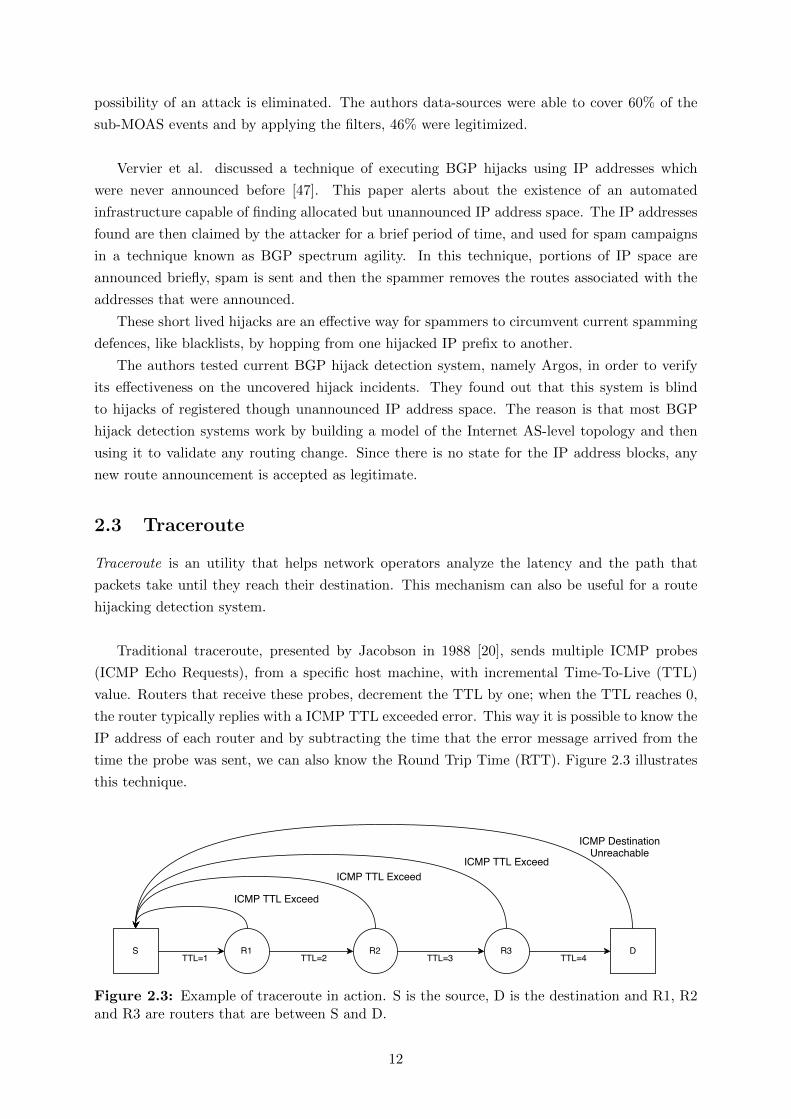
Traceroute is an utility that helps network operators analyze the latency and the path that
packets take until they reach their destination. This mechanism can also be useful for a route
hijacking detection system.
Traditional traceroute, presented by Jacobson in 1988 [20], sends multiple ICMP probes
(ICMP Echo Requests), from a specific host machine, with incremental Time-To-Live (TTL)
value. Routers that receive these probes, decrement the TTL by one; when the TTL reaches 0,
the router typically replies with a ICMP TTL exceeded error. This way it is possible to know the
IP address of each router and by subtracting the time that the error message arrived from the
time the probe was sent, we can also know the Round Trip Time (RTT). Figure 2.3 illustrates
this technique.
Figure 2.3: Example of traceroute in action. S is the source, D is the destination and R1, R2and R3 are routers that are between S and D.
12

Since ICMP probes have the disadvantage of being blocked by many firewalls [33], modern
versions of traceroute implementations use User Datagram Protocol (UDP) or TCP probes. TCP
probes have the advantage of not being easily blocked by firewalls, because of the difficulty in
differentiating TCP SYN probes to port 80 from normal web requests, but has the disadvantage
of requiring root privileges in order to be sent. UDP probes are more easily blocked by firewalls
but do not need root privileges [33, 22].
2.3.1 Anomalies
Regular traceroute fails when there are devices, that perform load balancing based on packet
headers according to [22]. Routers performing load balancing can propagate their traffic per-
flow, per-packet or per-destination policy. By transmitting per-flow, the router sends packets
of the same flow to the same interface. A flow is characterized by the following header fields of
the IP packet: source IP address, destination address, protocol, source port, destination port,
IP Type of Service (TOS) and checksum fields. So basically, different flows means different
routes and the problem with this is that UDP and ICMP probes from classical traceroute have
their header fields used in load balancing varied for the purpose of matching the corresponding
responses from routers to the probes sent.
The resulting anomalies that are caused by load-balancing are the following:
• Loops - Same node appears at least two times, one next to the other. Probes that are sent
to different paths get to a same node, originating multiple responses.
• Cycles - The signature of this anomaly is the appearance of the same address, say k, at
least two times separated by at least one address different from k.
• Diamonds - This anomaly occurs when multiple probes are sent to one node, and, due to
load-balancing, traceroute ends up displaying false links.
Aside from load balancing, that according to [12] is the main cause for anomalies in traceroute
results, Multi Protocol Label Switching (MPLS) and path asymmetry also cause anomalies.
MPLS is a mechanism in which routers forward packets based on labels instead of network
addresses. Traceroute can still work in routers supporting MPLS, because TTL field can be
copied from the original IP header to the MPLS header [41]. Yet there are some routers that
do not do this and because of this, these routers are not found by traceroute [22].
Finally due to path asymmetry, RTT values can suddenly become very high giving the idea
of a congested hops but in this situation it just means that the sending path is different from
the return path [22].
2.3.2 Anomaly-tolerant approaches
describe In this section we present some existing solutions that minimize the impact caused
by the described anomalies. We will begin by explaining a new tool that deals with load
balancers, continue with an algorithm to calculate the reverse traceroute that helps diagnose
13

RTT anomalies, and finally we will describe some extensions that can be used with traceroute
to provide the AS number of a router reliably and prevent denial of service of traceroute traffic.
Paris traceroute [4] avoids the problems posed by load balancers by keeping the header fields
used by load balancers constant, ultimately leading probes to a same route even in presence
of a per-flow load balancer. But it still needs to match responses packets, which is done by
varying header fields that are not used by load balancers. For UDP probes, it uses the checksum
field. For ICMP probes, Paris traceroute varies the Sequence Number and the identifier field.
According to evaluations made by Augustin et al. [4], anomalies like loops, cycles and diamonds
are significantly mitigated.
The reverse traceroute [25] is a distributed system supported by vantage points (servers)
which gather information to build the reverse path. The gathered information is useful for the
interpretation of RTT anomalies provided by the execution of traceroute. The steps for the
reverse traceroute are the following:
1. A number of vantage points perform traceroute to a source S, creating an atlas of paths;
2. Source S executes a Route Record (RR) ping to a destination D. This ping has the route
record option enabled, therefore only 9 hops are recorded;
3. Considering that the destination D is within 8 RR hops, at least one hop from the returned
path has been registered. The rest of the returned path can be built in an iterative manner;
If in step 3, S is not within 8 RR hops then there is a need to determine a vantage point that
satisfies the condition mentioned. Only users with significant amount of resources, may use this
approach to calculate the reverse traceroute since it requires vantage points placed in specific
locations across the network.
One extension to traceroute that provides useful information, for example to delimit network
boundaries, is the AS-number lookup. This can be done by accessing directly databases like
RIPE or Route-Views, for IP-to-AS mapping. Yet, according to [34], these databases have
incomplete and out of date information. The authors purpose to improve the mapping between
IP and AS by comparing BGP information and traceroute paths from multiple vantage points.
This way the traceroute tool periodically downloads the latest IP-to-AS mapping and uses it to
show the AS path associated with each traceroute probe the user launches.
Both the reverse traceroute and the IP-to-AS mapping proposed by [34] are techniques that
mainly depend on the ability to collect information.
The final extension presented here shows a way to detect malicious nodes that treat traceroute
and normal traffic differently. Secure traceroute [35] works like classical traceroute except for
the following characteristics:
• Hosts responding to the secure traceroute packets, provide the address of the next hop for
the packet. This way the element that initiated the operation always knows the expected
next hop.
14

• Before sending the traceroute packets, the tracer node establishes a secure channel for the
next expected hop with the purpose of mentioning the signature of the traceroute packets.
The signature could include the origin and the destination address of the packets plus a
constraint of a value of a certain field of the packet.
• Nodes receiving these secure traceroute packets respond to the tracer node with an agreed
upon marker and a secure message authentication code.
Figure 2.4 illustrates this technique where each router is asked to respond to traceroute traffic. In
this figure R3 does not confirm the reception, which could mean that R2 is dropping traceroute
packets. This method assumes the existence of a Public Key Infrastructure (PKI) that enables
a secure key exchange between an investigating and a investigated node. To minimize the cost
associated with this approach the method is initiated near the destination.
Figure 2.4: Example of secure traceroute in action. S is the source, D is the destination andR1, R2 and R3 are routers that are between S and D. S provides the signature (S1,S2 and S3)that traceroute packets will have to R1,R2 and R3. Only R1 and R2 confirm the reception ofthe packets.
2.4 Measurement of latency
By continuously measuring latencies between two end hosts it is possible to determine if packets
timings are normal or not, which may indicate a traffic hijacking attack.
One popular way to measure latency is by using the ping tool, which leverages ICMP [39]
to calculate the difference of the time in receiving echo reply packets and the time of sending
echo request packets. Yet, according to Pelsser et al. [37], latency values returned by ping have
high variance due to load balancing performed by routers which lead packets to different flows.
To cope with this problem, the authors came up with a variant of Paris traceroute, named
Tokyo-ping, which can estimate consistent delays even in the presence of load balancing. The
trick is to keep the header fields constant like in Paris traceroute, but unlike Paris traceroute
the flow-id is kept constant in the return path, which guarantees the same return path to all
measurement packets. The evaluation performed indicated that classic ping displays a consid-
erable more amount of jitter than the tool developed. Yet, the inability of executing the tool in
15

Linux systems is a significant drawback.
A simpler approach was used in 1993 by Bolot et al. [6]. They presented a study to determine
delays and loss behavior of packets, from end-to-end and in different time scales, by changing
the interval between probe packets. The tool used for the measurement is called NetDyn and the
idea behind the tool is to send regular UDP packets to a destination through an intermediate
node. A packet includes three timestamps fields to be filled by the source, intermediate node
and the destination. This tool does not deal with time synchronization of clocks, therefore in
all the experiments the source and the destination are the same machine. The source registers a
timestamp ts and a sequence number in the packet before sending it to the intermediate node.
The intermediate node writes its own sequence number and a timestamp and sends back the
packet. Finally the destination marks its timestamp td and calculates the RTT by subtracting
td with ts. Results showed that probe packets are lost randomly, except when the Internet traffic
intensity is very high. Although the results do not mean much in the context of today’s Internet
due to the year that the study was published, the technique to conduct the study is still relevant.
The next system, unlike the technique already described, measures latency without the active
cooperation of end-users. King [17] is a latency measuring tool that does not require deploying
an infrastructure of its own, because it uses Domain Name System (DNS) servers to calculate an
approximation of the latency of communication between two end-hosts. The main idea behind
King is supported by two observations, the first one is that end hosts are close to their DNS
name servers and the second one is that recursive DNS queries can be used to calculate latency
between two name servers. So basically if a client c wants to know the estimated latency be-
tween c and some target end-host t, it must first send a recursive DNS query to an authoritative
name server asking for the resolution of the name t, then this authoritative name server will
ask the authoritative name server of t. This server will send a response to c, thus having the
latency from c to the authoritative server of t. Next by calculating the latency between c and
his authoritative name server and subtracting these two latencies found, c obtains the measured
latency between c and t.
All approaches presented so far are capable of providing the RTT but not the One Way Delay
(OWD). The OWD represents the amount of time that traffic takes from source to destination.
Calculating the OWD can be hard because there needs to be a strict time synchronization and
access to both end-hosts. So many applications that do need these times, estimate them as
being RTT / 2. To investigate this assumption, Pathak et al. [36] performed experiments using
owping, a one way measuring tool that works by marking the time to a packet before sending
it, then at the destination, the time in the packet is subtracted from its current time. These
experiments were performed on 180 Research and Education Networks (GREN) nodes. The
traces collected consist of traceroutes, obtained with Paris traceroute, and OWD measurements.
The number of Internet paths that were continuously monitored were 10000. The metrics used
for the measurements were AS-level path asymmetry and router-level path asymmetry. The
results found indicate that, in commercial networks, delay asymmetry is very noticeable, that
16

asymmetry in the router level happens more times than asymmetry in the AS-level, and that
router-level asymmetry does not imply delay asymmetry where as delay asymmetry implies
router-level asymmetry.
Another important question that Pathak et al. [36] tried to answer is if delay asymmetry is
constant across time for two end-hosts. For this the fluctuations of forward and reverse delays
were logged, and the conclusions are that delay asymmetry changes when delay changes.
2.5 Attack source identification
In this section, we will begin by discussing the aspects of the Internet that makes IP traceability
difficult and continue with solutions that address these aspects with and without routers support.
According to Peng et al. [38], the Internet was made for scalability and not for security,
which led all the complexity to end-hosts while leaving the core networks simple. So routers do
not know the complete paths that packets take and are not capable of performing authentication.
This lack of functionality gives rise to a technique known as IP spoofing, where the IP address
source is forged. This technique is widely used to perform Distributed Denial of Service (DDoS)
attacks. The following solutions try to provide IP traceability even in the presence of IP spoofing.
2.5.1 Router-based approaches
The solution presented in [45] probabilistically marks packets by inserting edge information that
will enable the victim to reconstruct the route to the origin of the packets. Each packet header
has two fields reserved in the IP ID field. One is for the start and end of an edge and the other
one is for the distance field that represents the number of routers that the packet has traversed
since it was last marked.
The procedure for marking is the following: first, by a random probability, a router decides
to mark a packet, by writing the hash of its own IP address in the edge field and setting the
distance field to 0. If the distance field was already 0, then that means that the previous router
already marked the packet and thus what the router decides to do is to XOR the hash of its IP
address with the hash already present in the edge field, overwriting the value. Routers that do
not mark the packet, increment the distance field.
The reconstruction procedure made by the victim supposes there is an upstream router map
available. The idea is to divide all the edge fields based on the distance field. At distance equal
to 0, the victim will perform the hash function to all addresses of routers one hop away, present
in the map, and compare them with the edge fields. If there is a match then these addresses
are going to be included in the set of the reconstructed path. Using the addresses found, the
victim decodes the previous routers hop-by-hop. This approach has serious disadvantages like
the difficulty in deployment, all network nodes must be changed and the need of a lot of packets
to successfully reconstruct the path.
Pi [48] is a defense mechanism that like [45] relies on network support, but unlike [45] does
not need to reconstruct the path taken by packets from the attacker to the victim, which is
17

hard due to the limitation in space of the IP header. The key idea is to build a fingerprint in
the IP ID field, which is located in the IP header. The fingerprint will characterize a certain
path. If a fingerprint matches an attacker identifier then all the subsequent packets, with this
identifier, will be dropped, ultimately leading the victim into a proactive role. The algorithm for
marking involves a router selecting n bits from the hash of its IP address and the previous hop
IP address. The consideration of both these fields helps avoid collisions. The n bits are written
in the IP ID field, in a position which is calculated through TTL mod [16/n]. One limitation of
this marking scheme is that the IP ID field is of limited size therefore markings done by routers
further away may be overwritten by routers closest to the victim. The authors of the paper try
to minimize this by preventing any markings from routers who are in the same AS of the victim.
2.5.2 Victim-based approaches
Solutions that are router-based fall short in comparison with victim-based approaches in terms
of deployment since a potential victim has much more incentive in deploying security measures
than a network service provider.
One example of these victim-based approaches is Hop-Count Filtering (HCF) [21]. This
solution is supported by the notion that an IP addresses can be spoofed but the number hops
made by packets cannot. The idea is to have a mapping table IP-to-hop-count and, depending
on the the information registered, receiving traffic is dropped or not.
Since the hop-count is not directly in any field of an IP packet, it has to be calculated
through the TTL field. This value is decremented hop by hop from the source to the destination,
therefore the hop count will be the initial TTL minus the final TTL. The problem with this
is that the initial TTL varies from machine to machine but according to a study made by the
Swiss education and research network [1], modern operating systems use a small set of initial
values therefore this value can be inferred.
To be able to build an efficient IP-to-hop-count table, the following objectives must be
achieved,
• Accurate IP to Hop count mapping;
• Up-to-date IP to Hop count mapping;
• Moderate storage requirement.
In order to reduce the space requirements, the authors executed a technique called IP Address
Aggregation where hosts are grouped according to the first 24 bits and the groups formed are
divided even more based on hop-counts.
For an attacker to successfully evade such a table, it is necessary to set an initial TTL value
T’ for each packet such that the difference between T’ with the number of hops hz from the
flooding source to the victim, is equal to the difference between the initial TTL value T and the
hop count hs from the spoofed IP address and the victim. The attacker can easily calculate hz,
by performing traceroute, and infer T. Yet the calculation of hs from a randomly selected IP
address requires the attacker to build an a priori hop count table, which is much more difficult
18

than building the table from the victim since the attacker does not have access of the final TTLs
of normal traffic. The need for a significant amount of updates to keep the system up-to-date is
a drawback of the system.
2.6 Avoidance routing
Avoidance routing is a technique to steer traffic around a specific zone [27]. Systems that re-
spond to network failures by performing avoidance routing, need first to locate the area to avoid.
These detection mechanisms may prove to be relevant for our work. Furthermore, by evading
the ASes where it is known that the hijacking attack takes place it is possible to prevent these
attacks. The following works present mechanisms for performing avoidance routing, whereas the
last describes a way to prove that traffic did not traverse a certain forbidden region.
In the method explained by Kline and Reiher [27], users set security properties that they
wish to avoid in their avoidance request. Security properties are information regarding the
geopolitical location, ownership and router type. Routers are configured to be aware of their
own security properties. A router, by receiving an avoidance request, starts looking for a route
to the destination that satisfies the security properties defined in the request. If a route is found
then the request is forwarded to that route, if there is no path with the correct conditions then
the router will start a depth first search sending request messages to all interfaces, by turn,
which route to the destination. It will stop if it receives a success message, meaning that a path
was successfully found, or if it receives failure messages from all of them which means that no
route was found. The overhead associated with the verification of the security properties is non
negligible.
LIFEGUARD [24] is a system which has the purpose of increasing Internet availability to
networks where hosts reside, also known as edge networks. It uses a set of techniques that allow
the location of failures, even in the presence of asymmetric routing, and the rerouting around
outages. The rerouting is made by using the BGP loop-prevention mechanisms in which an
edge network O, puts the number of the AS A into path advertisements, marking A as already
visited and consequently leading to the rejection of the announcement upon arrival to A, and
the withdrawal of the path from its neighbors, forcing all these ASes to find routes to O that do
not involve A. The failure detection system employed by LIFEGUARD involves four steps.
• The first one is to keep information on the round-trip times between the source and the
destinations to distinguish what times are normal and what times are not, eventually
generating candidates to failure locations.
• In the second step, LIFEGUARD isolates direction of failure using spoofed pings from
vantage points. For example if these probes reach the vantage points and not the source,
it means there is a problem in the reverse path.
• For the third step, the intention is to narrow down the point of failure in the not working
direction. If the problem is in the forward direction, then LIFEGUARD uses traceroute
19

to measure the portions of the working path. If it is in the reverse path, vantage points
perform pings to all nodes in the forwarding path, and then execute reverse traceroute to
all pingable nodes.
• Finally, in the fourth step, hops that were pingable from the failure direction are removed
from the candidate set. The first unreachable hop does not have a functional path to the
source and therefore rerouting around it may return connectivity to the source.
The next and final system of this section, guarantees that network traffic passed or not in
some zones in the network.
The key idea behind alibi routing [32] is to provide proofs that traffic that passed on a node
did not traverse certain geographic regions. Thus this relay node is called an alibi in a point
that it confirms or not if traffic has traversed a forbidden region. To prove this, the authors
find an alibi where the latency for the traffic to reach a destination traversing any node in the
forbidden zone and the alibi node is much bigger than going via alibi node alone. When an alibi
receives a packet, it signs it and sends the signature to the source as a proof of avoidance. All
the source needs to do is to send a query to a peer in the overlay network, specifying a region
to avoid, a destination and the identification of a peer that probably is not in the forbidden
region. In order to try to avoid a forbidden region, a peer q will forward the query to a peer n
if the latency between q and n is bigger than the latency between q and the closest node in the
forbidden region. There is no mention in the paper about how trusted peers are found and for
this reason it implies that all participating nodes are trusted.
2.7 Summary
Table 2.1: Comparison of different latency estimation tools
Tool Approach Metric Advantage Disadvantage
Ping Host based RTTIntegrated in every
operating systemsLatencies highly varied
Tokyo-Ping Host based RTTConsistent latencies
measurements
Not operational
in Linux systems
NetDyn Host based RTT Low Overhead Clock synchronization
King DNS based RTT No infrastructure neededHosts need to be
close to DNS servers
Owping Host based OWDSeparation of forward
and reverse delayClock synchronization
The previous sections describe various techniques that allow route monitoring. Section 2.3
demonstrates how different traceroute tools work using ICMP, UDP and TCP. It also showed
problems associated to classical traceroute, which involved the load balancers and asymmetry
of the network, and solutions that minimize these problems using Paris traceroute and reverse
traceroute. Therefore, the combination of Paris traceroute and reverse traceroute enables more
reliable results. In Section 2.4 different measuring tools were discussed. Table 2.1 presents a
20

Table 2.2: Comparison of different IP traceback methods
Solution Approach Method Advantage Disadvantage
IP marking
schemeRouter-based Path reconstruction
Low overhead
to routers
Need a lot of packets to
reconstruct path
PI Router-based Path identificationDoes not need
full path
Path differentiable
markings may be
overwritten
HCF Victim-based Hop count Easy to deploy Constant need of updates
comparison between the tools. Among these tools, owping is apparently the best because it
separates the forward latency from the reverse latency providing more useful information for
applications like streaming. Tokyo-ping is also interesting because it is an adaptation of Paris
traceroute and for that reason it provides more reliable information. Section 2.5 illustrated
ways to perform IP traceback even if attackers perform IP spoofing, these mechanisms are
useful for our work because they provide an idea of the path that packets take until they reach
a destination. Three approaches were presented and a comparison between them is shown in
Table 2.2. HCF has a significant advantage in relation to the other two approaches because,
since it is victim based, it is much easier to deploy. Finally in Section 2.6, systems that increase
availability by performing avoidance routing were presented. The techniques used by these
systems are relevant to our work because, before avoiding a network area they locate the area
to avoid. Between the systems, LIFEGUARD [24] stands out. LIFEGUARD uses an outage
detection system which can be successfully performed even in the presence of asymmetric routing.
21

22

Chapter 3
DARSHANA
In this chapter we discuss the mechanisms, system operation and specifications of DARSHANA.
The main objective of the system is to help senders of Internet traffic identify when their traffic
is being hijacked by carefully monitor network metrics (RTT, hop count and propagation delay)
and the path that packets take.
Section 3.1 presents the different mechanisms used and how they can detect route hijacking,
Section 3.2 illustrates how the system operates and connects the different mechanisms and finally
Section 3.3 shows the implementations decisions for the system.
3.1 Mechanisms used in the system
This section presents the mechanisms used in DARSHANA, how they work, how can they detect
route hijacking, their advantages and disadvantages. The mechanisms are the following: Mon-
itoring network latency (Lat), Estimating hop count (Hop), Calculating path similarity (Path)
and Monitoring propagation delay (Prop). Table 3.1 presents a summary of the mechanisms.
Table 3.1: The methods, benefits and drawbacks of the mechanisms presented in Section 3.1
Mechanism Detection Benefits Drawbacks
Monitoring network latencyHigh latency could mean traffic
hijack.Easy to measure.
Latency is also affected
by congestion so it does not
indicate hijacking with certainty.
Estimating hop count
The hop count is usually stable, so
high increase in hop count could be
induced by traffic hijack.
Usually stable.
Link failures and legitimate
route changes may trigger
alteration in the network
topology.
Calculating path similarity
Paths may end up showing
significant disagreement when there
is a traffic hijack, since traffic
takes a detour to the hijacker.
Filters small legitimate
route changes.
Not all dramatic route changes
are the result of traffic hijack.
Monitoring propagation delay
Propagation delay gives the time
that a bit takes in the wire, meaning
that in a hijacking event this metric
may show an anomalous value.
Provides insights about the
attack even when traceroute
does not give results.
Requires a period of
initialization, to estimate
all the other latencies.
23

3.1.1 Monitoring network latency (Lat)
One of the metrics used in our system is the RTT. Each node that is monitoring another (node)
keeps information about the total time that each packet takes from source to destination and
from destination to source. In a hijacking event the end-to-end latency between a certain source
and a destination tends to change significantly. Measuring the RTT has some benefits like low
overhead and the fact that time is a factor that is hard for an attacker to evade. On the other
hand, an increase in RTT is difficult to distinguish from network congestion.
We designed a new version of ping that we denominate cryptographic ping, the mechanism is
illustrated in Figure 3.1. The objective is to avoid that an adversary responds to a ping request
earlier, before the request reaches the destination, leading to readings of RTT that are lower
than the real value. The new mechanism works as follows. The machine that is monitoring A
marks time (Timestampi) and sends a nonce to a machine that is being monitored B. B will
cipher the nonce with its private key (PRB) and send it back. A marks the time (Timestampf )
and will verify the received signed nonce by applying the public key of B. If the nonce matches,
A calculates the round trip time by subtracting the last marked time from the first marked
time. Without this ping, the hijacker, since he has hijacked the traffic, could send ping response
messages to A on behalf of B, ultimately fooling the system. This way we can guarantee
authenticity and uniqueness. This requires that the server must run code and share his public
key that must be known or certified by a trusted certificate authority.
Figure 3.1: Cryptographic ping, where host A calculates the RTT between itself and host B.
3.1.2 Estimating hop count (Hop)
We propose adding the network distance measured as hop count, the number of intermediate
devices between a source and a destination, as one more criteria to detect route hijacking attack.
According to [51], the hop count to a certain destination generally remains unchanged over time.
When a prefix is hijacked, the hop count tends to change. In an interception attack, the traffic
takes a detour to the AS of the hijacker, then it is forwarded to the legitimate destination. This
deviation can change significantly the hop count if the hijacker is far from the source, which is
likely due to the size of the Internet. Figure 3.2 shows the normal and the deviated network
24

distances (d and d′), where both h and h′ announce a prefix P (not in the figure) in which D
belongs. The value of Q = d′
d gives an indication of the likelihood of prefix P being hijacked.The
Larger Q is, the more likely P has been hijacked.
On the contrary of the RTT, the hop count is not affected by congestion. However, other
less frequent events link failures and operational route changes may affect it.
Figure 3.2: Normal and deviated distance networks when both h and h’ announce the prefix ofD. S is the origin of Internet traffic, D is the destination and h and h’ represent different ASes.
3.1.3 Calculating path similarity (Path)
The system tracks the path that packets are following. It periodically stores the path obtained
using traceroute and translate the IP found to Autonomous Systems Number (ASN). This map-
ping increases accuracy because we only need one router from a autonomous system to correctly
obtain a path that packets are taking. The correlation between the new path measurement and
the previous path measurement may provide insights about the occurrence of the attack. In an
hijacking event, since the traffic has taken a detour, the paths measured may end up showing sig-
nificant disagreements. The level of these disagreements differentiates legitimate route changes
from the hijacking situations, legitimate changes are not expected to result in a dramatic route
change. This mechanism has more overhead than the previous two, because by obtaining the
full path between two end hosts it is necessary to receive a message from each router in the
path. Figure 3.3 presents the concept of path disagreement. Figure 3.3(1) represents the path
from origin of traffic S to destination D, Figure 3.3(2) shows a possible legitimate route change
and finally Figure 3.3(3) reveals the path from S to D but this time the traffic has been hijacked
(intercepted) by H. There is more disagreement between paths from Figures 3.3(3) and 3.3(1)
than from paths of Figures 3.3(2) and 3.3(1).
3.1.4 Monitoring propagation delay (Prop)
We propose a new technique that isolates the propagation delay from the RTT and uses this
metric to declare a route hijacking. This technique is divided in two phases. The first phase
uses the results from the Lat mechanism to estimate the sum of all latencies belonging to RTT
except the propagation delay. The second phase is activated only if the system stops obtaining
results from the Path mechanism, indicating an attacker is interfering with this mechanism.
25

Figure 3.3: Path disagreement concept where (1) demonstrates the original path, (2) showsthe path after a legitimate route change and (3) presents the path after a route hijacking event.
Phase one Consider that the RTT can be decomposed in the following delays: transmission
delay (σtrans), propagation delay (σprop), queuing delay (σqueue) and processing delay (σproc) as
shown in RTT = σtrans + σprop + σqueue + σproc. The propagation delay is the time that a bit
takes in the communication medium from a node to another node. This delay can be calculated
as the ratio between the link length and the propagation speed on that medium.
The system uses the IP addresses of the origin and the destination to obtain their approx-
imate geographical coordinates. This involves accessing a remote database, which is why this
mechanism has more overhead than the first two mechanisms. The link length is calculated by
computing the shortest distance between both. For the propagation speed, we make a conser-
vative approximation by considering that all nodes are connected with fiber-optics, which has
higher propagation speed than alternative media (cooper, air). We use the usual approximation
that fiber-optics operate at 2/3 the speed of light [2]. The minimum possible propagation delay
is given by σprop = 22c3
× ShortestDistance(o, d) (the factor of 2 in the numerator captures the
fact that this propagation delay is in relation to the RTT) where o represents the origin, d is
the destination and c is the speed of light. Simplified, the formula is as follow:
σprop =3
c× ShortestDistance(o, d) (3.1)
Besides the propagation delay, the system estimates the sum of the others latencies (σtrans,queue,proc)
by σtrans,queue,proc = RTT − σprop.
Phase two When the system obtains an anomalous RTT and stops receiving results from
Path, it selects the minimum value of σtrans,queue,proc and the maximum value of the RTT
estimated. By max (σprop) = max (RTT )−min(σtrans,queue,proc), we obtain an upper bound on
the value of the propagation delay. This allows drawing a circle around the source with a radius
r that represents the maximum propagation delay (Figure 3.4). If the distance between d and o
is greater than r we detect a route hijacking. This mechanism allows detecting route hijacking
even if the Path measurements cease to exist. However, it requires a period of initialization, to
estimate the different latencies.
26

Figure 3.4: The maximum propagation delay is represented as a circle defined by the source owith radius r where the destination d is inside of the circle.
3.2 System operation
This section describes how DARSHANA operates. Figure 3.5 divides the mechanisms presented
in the previous section in components and presents their relations. DARSHANA has the follow-
ing components:
• Active Probing: In this component three mechanisms come into play. The system con-
stantly takes values for RTT, hop count and the path that packets are taking. The system
probes the RTT more often because this is the mechanism with the lowest overhead. Upon
detecting an anomaly in the RTT the system passes to more reliable mechanisms, as this
anomaly could only mean a temporary congestion in the network. The next mechanism
is estimating the hop count, for the reasons explained in Section 3.1.2. This metric is
more reliable than RTT so it is used to filter out small legitimate changes. Obtaining it,
results in more overhead than getting the RTT but less overhead than obtaining the full
path. This component also executes the first phase of monitoring propagation delay in
parallel with the other two mechanisms, calculates this delay with the shortest distance
in a straight line between the source and the destination and estimates the other latencies
belonging to the RTT.
• Path Similarity Detection: Traceroutes with different protocols (ICMP, UDP, TCP) are
issued. The system uses different protocols because routers may be configured to block
certain protocols [33]. The path that contains the most nodes is chosen and stored. If
enough results were received, then the new path will be compared with the last path
obtained by the Active Probing. Disagreement above a certain threshold may indicate the
existence of the attack.
• Propagation Delay Validation: In case no conclusive results are received from path simi-
larity detection, the max (σprop) and the anomalous(σprop) are calculated. The maximum
propagation delay is computed by max (σprop) = max (RTT )−min(σtrans,queue,proc). The
anomalous propagation delay is calculated with anomalous(σprop) = anomalous(RTT ) −max (σtrans,queue,proc). This calculated propagation delay is compared with max (σprop).
• Hijacking declared: Upon the method chosen, conclusions about the hijack are made and
presented to the sender of the traffic.
27

Figure 3.5: Fluxogram of DARSHANA, with the mechanisms organized in different compo-nents
3.3 The system in detail
In this section, we present the implementation decisions of DARSHANA. The system receives
continuous information about data that it needs to detect a route hijacking. This data involves
latencies, hop count and paths.
• Active probing: DARSHANA issues cryptographic pings and Paris traceroute [4] probes
with different periods. Paris traceroute is known to evade anomalies like loops, cycles
and diamonds. These anomalies stem from the fact that a load balancer sends probes of
traceroute to different interfaces based on the header of the probes. By not varying the
fields used by a load balancer, Paris traceroute enables probes to be forwarded in the same
interface even in the presence of a load balancer.
Three values are obtained by executing traceroute: hop count, traffic path and propagation
delay. For calculating the hop count we use Paris traceroute. We only need to execute
a partial traceroute with a TTL that is close to the destination in the majority of times.
TTL = 1 is only used when we do not know about the destination.
We characterize the traffic path in terms of a set of autonomous systems, so each node of
28

the result of the traceroute is mapped to the corresponding autonomous system using the
CYMRU database1.
Finally, the propagation delay is calculated by first, translating the IP of the source and
destination to geographical coordinates using MaxMind database2, then the shortest dis-
tance is calculated between them and passed to the propagation delay by using the formula
presented in Section 3.1.4.
Each iteration of the cryptographic ping gives a new sample of RTT and by subtracting
the RTT with the propagation delay, we estimate the other latencies of the RTT.
• Path Similarity Detection: New samples of RTT and hop count are compared with the
exponential weighted moving average of past samples. The formula for the average is
the following: sample = (1 − α) × sample + α × samplenew. The moving average allows
DARSHANA to adapt to the normal changes in the network. If the quotients between the
new samples of both RTT and hop count with the exponential weighted moving average
passes certain defined thresholds TLat and THop, Paris traceroutes are issued to the
destination in an attempt to reveal the cause of the anomalies. If there are enough elements
in the resulted path, then this path is compared to the last path stored. The comparison of
these two paths can be computed from path and path ′ using the Sorensen-Dice coefficient:
sim = 2|path ∩ path ′|/(|path|+ |path ′|). This gives the similarity in a number that ranges
from [0,1]. 0 means that there is no similarity at all and 1 means that the items of the two
paths are the same. If the similarity is less than a certain threshold TPath, then a route
hijacking is declared.
• Propagation Delay Validation: In case the traceroutes executed in the previous mod-
ule do not produce any results, DARSHANA calculates the σprop with the RTT and
σtrans,queue,proc that were estimated. More precisely, the system will compute the max (σprop),
by subtracting the max (RTT ), found before the anomaly, and the min(σtrans,queue,proc).
This computed delay will be compared with anomalous(σprop) resulted from the subtrac-
tion of the anomalous(RTT ) with the max (σtrans,queue,proc). Ifanomalous(σprop)
max(σprop)is higher
than a defined threshold TProp, then a route hijacking is declared. It is important to
note that we never do calculate the propagation delay associated to the hijacking attack.
The estimated σtrans,queue,proc still belongs to the normal path between source and desti-
nation. We only observe that the anomalous(RTT ), does not belong to the pattern of the
propagation delays constructed.
3.4 Summary
In short, DARSHANA is able to detect a route hijacking attack in two ways. The first requires
the existence of traceroute data; by detecting anomalies in both RTT and hop count, the con-
clusion about the attack is given by the similarity between the path observed after detecting
the anomalies and the path observed before any anomaly was seen. The second way enters in
1http://www.team-cymru.org/IP-ASN-mapping.html2http://dev.maxmind.com/
29

action when in a given time, anomalies were observed in RTT and hop count and by conducting
traceroutes no conclusive results were returned. The conclusion about the attack will be given
by comparing the propagation delay, associated with the anomalous RTT, and the maximum
propagation delay ever observed.
30

Chapter 4
Evaluation
In this section we describe how we performed the simulation of a prefix hijacking and the exper-
iments that were conducted to validate our proposed implementation in terms of performance
and cost. The objective of the experimental evaluation is to answer two important questions: (1)
How effective are DARSHANA and its sub-mechanisms in detecting attacks? (Section 4.2) (2)
How many times is DARSHANA forced to execute techniques with higher overhead in normal
conditions when there is no attack? (Section 4.3)
The experimentation were done in PlanetLab Europe1 and AWS EC22. PlanetLab offers an
increased number of nodes which provides more choice to build scenarios. However the restriction
of only being able to access nodes from Europe limits the testing in more global scenarios.
AWS permits access to instances in different continents but does not provide much geographical
diversity. With PlanetLab we use nodes from Portugal (POR), Ireland (IRE), France (FRA),
Germany (GER) and Poland (POL). From AWS we used instances from N. Virginia (VA),
N.California (NA) and South Korea (S. Korea). Figure 4.1 shows a world map with all the
nodes used from PlanetLab and AWS marked in black circles and squares, respectively.
Figure 4.1: Nodes used from AWS and PlanetLab
1https://www.planet-lab.eu/2https://aws.amazon.com/
31

4.1 Simulating route hijacking attacks
Before we present the tests done, it is important to explain how the simulation of the attacks
is made. We simulate only the interception attack because the blackhole attack ends up being
just an interruption of communication, therefore it is easy to detect.
In order to simulate the attack, we need three nodes: one node that is the source of the
Internet traffic; a node that will serve as the destination; and another node that is trying
to hijack traffic by receiving it and then sending it to the legitimate destination. When the
attack is successful, given an hijacker H, a source S and a destination D, as depicted in Figure
4.2, the RTT (RTTS−D), the hop count (hopcountS−D) and the path (pathS−D) from S to D
will be RTTS−D = RTTS−H + RTTH−D, hopcountS−D = hopcountS−H + hopcountH−D and
pathS−D = pathS−H ∪ pathH−D, respectively.
Figure 4.2: Simulation of an interception attack
4.2 Performance of the system
In order to evaluate the performance of DARSHANA, we measured the amount of times that it
can detect an attack and calculated the false positives in different scenarios. The false positives
indicate the percentage of false route hijacks reported. We tested for each individual mechanism,
Lat, Hop, Path, Prop; and for a full scheme that is the combination of Lat + Hop + Path. The
tests were done for small scale and for historical real prefix hijacks. For each scenario the
experiment was repeated 30 times.
4.2.1 Small scale scenarios
We tested small scale scenarios with nodes from PlanetLab. Each scenario is composed by three
nodes. Two of them have a source-destination relation and the third one serves as the hijacker.
Throughout the scenarios the source and the destination are fixed and the hijacker varies its
distance to the source. We selected a node from Portugal as the source, a node from Ireland as
the destination and the hijackers are nodes from France and Poland. The distances from source
to hijacker were chosen in a way that would enable to determine the cases when DARSHANA
has more difficulty in detecting the attack. The results are presented in Figures 4.3 and 4.4.
32

Lat
Hop
Prop Path
DARSHANA
0
50
100
soft
medium
hard
Figure 4.3: The percentage of times that each mechanism detects a simulated route hijackingattack. The scenario involves Portugal as the source, Ireland as the destination and France asthe hijacker. The labels soft, medium and hard represent different sets of thresholds for eachmechanism.
Lat
Hop
Prop Path
DARSHANA
0
50
100
soft
medium
hard
Figure 4.4: The percentage of times that each mechanism detects a simulated route hijackingattack. The scenario involves Portugal as the source, Ireland as the destination and Poland asthe hijacker.
The figures show the percentage of times that each mechanism detects a simulated route
hijacking attack under different scenarios. Each figure contains three labels; soft, medium and
hard. They specify qualitatively the thresholds that were used for each mechanism. There are
four thresholds, TLat, THop, TPath and TProp, that indicate how much measurements of RTT,
hop count, path and propagation delay have to deviate in order to declare a route hijacking.
The values of the thresholds used in the experiments were defined based on many experiments
done before the evaluation reported here. These values are presented in Table 4.1.
Observing the results, we can conclude that soft thresholds lead Lat to detect all hijacks.
However, this also leads to false positives and, in the case of DARSHANA, prevents the other
mechanisms from actuating and removing such false positives, while keeping a high detection
rate. The Hop and the Path mechanism present 0 or 100% values. This is due to the fact
33

that these mechanisms provide constant results through time. Therefore for certain values of
THop and TPath, these mechanisms will detect or not the simulated attack. In regard to the
propagation delay mechanism and observing Figures 4.3, 4.4 and Table 4.1, the hard label in
Figure 4.3 corresponds to TProp = 4.6 and the soft label in Figure 4.4 is equal to TProp = 7.4.
In Figure 4.4 with the soft label, the detection of the attack is very close to 100%, but by
observing Figure 4.3 we can see that for the hard label, this mechanism can only identify the
attack less than 50% of the times. This means that changes in propagation delay are much more
observable as the hijacker increases its distance to the source of the traffic. When the source
and the hijacker are close, the packets do not traverse many different autonomous systems and
so DARSHANA is not able to detect the hijack with the hard thresholds.
4.2.2 Real scenarios
While our analysis in the previous section provided some insights about the capacity of detection
of our system, we wanted to test our detection mechanism using historical prefix hijacking
events and confirm that our mechanism behaves better by having the hijacker farther away.
We simulated two scenarios. It was not possible to choose nodes from the exact locations in
which these scenarios took place so we chose nearby nodes. The first scenario corresponds to
the Belarusian Traffic Diversion [11], where traffic from New York was diverted to Belarusian
ISP GlobalOneBel before arriving to the intended destination, Los Angeles. To simulate this,
we deployed two nodes (micro-instances) in two different Amazon AWS regions: N. Virginia
and N. California. The node from N. Virginia is the source, the node from N. California is
the destination. We used a node from PlanetLab in Poland to serve as a hijacker and to
represent the Belarusian ISP GlobalOneBel. The second scenario emulates the China 18-Minute
Mystery [10], in which, allegedly, traffic between London and Germany took a detour through
China. We simulate this by selecting a node from PlanetLab in Ireland as the source, a node
from Germany as the destination and a micro-instance of Amazon AWS in Seoul as the hijacker.
The results can be found in Figures 4.5 and 4.6.
Lat
Hop
Prop Path
DARSHANA
0
50
100
soft
medium
hard
Figure 4.5: The percentage of times that each mechanism detects a simulated route hijackingattack. The scenario involves N. Virginia as the source, N. California as the destination andGermany as the hijacker.
34

Lat
Hop
Prop Path
DARSHANA
0
50
100
soft
medium
hard
Figure 4.6: The percentage of times that each mechanism detects a simulated route hijackingattack. The scenario involves Ireland as the source, Germany as the destination and SouthKorea as the hijacker.
Table 4.1: Values of thresholds used for each scenario. S, D and H are the source, destinationand hijacker, respectively.
S:POR — D:IRE — H:FRA S:POR — D:IRE — H:POL S:VA — D:CA — H:POL S:IRE — D:GER — H:S.Korea
Mechanisms Soft Medium Hard Soft Medium Hard Soft Medium Hard Soft Medium Hard
Lat 1.2 1.3 1.4 2.1 2.2 2.3 3.6 3.65 3.7 13 13.5 14
Hop 1.05 1.1 1.15 1.05 1.1 1.15 2.05 2.1 2.15 2.2 2.25 2.3
Path 0.9 0.8 0.7 0.9 0.8 0.7 0.9 0.8 0.7 0.9 0.8 0.7
Prop 3.6 4.1 4.6 7.4 7.9 8.4 12.5 13 13.5 70 75 80
In these scenarios there is substantially more change, between the samples after attack and
the samples prior to the simulated attack, than in the small scenarios experiments. The values
used for the thresholds are shown in Table 4.1.
To better understand why DARSHANA presents superior detection values in relation to the
experiments done in Section 4.2.1, we need to have an idea of the paths that packets take from
source to destination, before the hijacking and after the hijacking.
Table 4.2: Numbers of the ASes that packets traverse, separated by commas
Hijacker
From - To
POR - IRE IRE - GER VA - CA
Normal Hijacked Normal Hijacked Normal Hijacked
FRA 1930,21320,1213 1930,21320,2200,15557,1213 - - - -
POL 1930,21320,1213 1930,21320,8501,8890,1213 - - 1650916509,2603,8501,
8890,16509
S.Korea - - 1213,21320,6801213,3356,2516,
16509,4766,174,680- -
Table 4.2 shows the number of the ASes the traffic traverses, before and after the attack. It
is possible to observe that the normal path and the hijacked path from the small scale scenarios
share more numbers than the paths from real case scenarios. Furthermore, detecting the attack
between two instances of Amazon AWS is easy, because there is not a lot path diversity as we
35

can see from the normal path between N. Virginia and N. California.
4.2.3 False positives
There is a false positive when a scheme claims to have detected an attack that did not exist.
Measuring the false positives for DARSHANA was a challenge, because the system uses the
Hop mechanism that displays constant results and thus DARSHANA was not able to pass to
the next mechanisms (Path and Prop). We decided to evaluate the false positives for each
individual mechanism of our system during a run of 1h15m. The false positives were calculated
by running each detection mechanism with scenarios without executing the attack (i.e., without
hijacking). By capturing the amount of alerts given by a mechanism we get the false positive
rate #alerts/#samples, where #alerts is the number of alerts and #samples the number of
samples taken.
We tested for three different scenarios and each scenario contains a source and a destination.
For the first scenario, we chose a node from POR as the source and a node from IRE as the
destination; in the second, the source is a node from IRE and the destination is a node from
GER; finally, for the last scenario, the source is a node from VA and the destination is a node
from CA.
For Path and Hop the number of false positives observed was 0, because there would have
to be legitimate route changes to cause them, but they are not frequent and none was observed.
For Prop the number of false positives was also 0, as the mechanism always searches for the
maximum RTT stored to compute the maximum propagation delay ever observed. Unless a
great anomaly in RTT is found, the mechanism will not raise an alarm. For Lat, we received a
new sample from 30 to 30 seconds getting a total of 150 samples per scenario. The results are
presented in Figure 4.7. The first set of three columns correspond to the POR to IRE scenario,
the second set to IRE to GER, and the third to VA to CA. Each column shows the false positive
rate for a certain TLat. The values for the thresholds were chosen with the objective to reveal
variation in the false positive rate. As we can see in all sets of columns the false positive rate is
bigger for softer thresholds. This makes sense since small thresholds mean that little changes in
RTT are considered an attack. For the soft label the value used was 1.2, for medium the value
was 1.3 and for the hard label the value chosen was 1.4.
One of the conclusions obtained in Section 4.2.1, is that softer thresholds should be chosen
for the Lat mechanism when it is part of DARSHANA. Although this experiment showed that
softer thresholds result in more false positives, other more heavy mechanisms do a pretty good
job at filtering out these false positives. The results for DARSHANA were obtained with the
soft thresholds for Lat. However, on the contrary of Lat the false positive rate for DARSHANA
was 0 in all scenarios, as the other mechanisms (Path, Hop, and Prop) filtered the false positives
of Lat, leading to 0 false positives as obtained with which of the 3 individually. This is precisely
the benefit of combining algorithms that we aimed to achieve with DARSHANA.
36

0.033
0.027
0.06
0.02
0.013
0.033
0.007 0.007
0.013
VA-CA
Soft
Medium
Hard
POR-IRE
Fal
se P
ositi
ve R
ate
IRE-GER
Figure 4.7: False positive rate of RTT in different scenarios. The Y axis refers to the falsepositive rate and the X axis represents the different scenarios tested.
4.3 Cost
DARSHANA keeps probing for RTT with a certain period k. Unless anomalies in RTT are
verified, leading the system to techniques with bigger overhead like Hop and Path. We evaluate
the cost as how many times DARSHANA is forced to execute more heavy techniques in normal
conditions (i.e. without simulating the attack). The scenarios used were the same as in Section
4.2.3. The probing rate of RTT was set to 60 seconds.
Figure 4.8: RTT values in different scenarios. The Y axis refers to the RTT values in mil-liseconds and the X axis represents the number of samples.
Figure 4.8 illustrates the values for round trip time in different scenarios. As we can see from
this figure, the samples for the RTT for each scenario do not differ much. The mean deviations
of the samples were low. The scenario with POR and IRE, has a mean deviation equal to 2.4
ms, the scenario involving IRE and GER has the lowest mean deviation equal to 1.2 ms and
finally the scenario with VA and CA has the biggest mean deviation of 5.02 ms. This implies
37

that the RTT usually remains constant, being difficult to observe anomalies and pass to more
heavy methods. Considering a value of TLat = 1.5, the total ping and traceroute messages for
this period have the following formulas, where #Msg Ping and #Msg Traceroute correspond
to number of ping and traceroute messages, respectively:
• #Msg Ping = T × k
• #Msg Traceroute = #Msg Pingn
The T is the total time of the experiment, k is the ping period and n is the traceroute period. For
this experiment #Msg Ping = 100×1 = 100 ping messages and #Msg Traceroute = 1005 = 20
traceroute messages. All of this demonstrates that even for low values of TLat, the variation of
the RTT in normal conditions is not enough to force the system to execute more heavyweight
techniques. Thus the total #Msg Ping and #Msg Traceroute end up only being dependent
on k and n.
4.4 Summary
The main conclusions of the evaluation chapter are:
1. When the hijacker is very close to the source it is difficult to detect the hijack with hard
thresholds.
2. The values for TLat must be low in order to allow more heavy methods execute and filter
out false positives.
3. Change in Propagation delay is more observable as the hijacker increases its distance from
the source of Internet traffic.
4. DARSHANA presents better results when packets traverse a greater number of ASes.
5. The combination of algorithms allows DARSHANA to filter false positives generated with
the Lat mechanism, since Hop and Path show constant results through time and the Prop
mechanism needs a great anomaly in RTT in order to declare a hijacking.
6. Even for low values of TLat, in normal conditions, the times that DARSHANA executes
more heavy mechanisms is only dependent on ping and traceroute periods.
38

Chapter 5
Conclusion
The problems associated to BGP have been well-known for over two decades. A lot of solu-
tions were proposed but they could not ensure deployability, unless for ISPs and big Internet
companies, or are avoided easily by attackers countermeasures.
In this thesis we have presented DARSHANA, a redundant route hijacking detection system.
By only applying active probing methods, we ensure accuracy and deployability. Different
techniques turns the system redundant enough to not be avoided by attackers. The design of
the detection system minimizes the overhead, by using techniques with low overhead more often.
Techniques with greater reliability and overhead are only executed when there is a need to. Our
system is the first to use the propagation delay in this context, providing one more metric for
the purpose of detection.
We evaluated the system with small scale and historically real route hijacking events. One
of the conclusions obtained is that softer thresholds should be chosen for the Lat mechanism
when it is part of DARSHANA in order to let more heavy mechanisms execute. Although the
tests shown that DARSHANA is incapable to detect the attack with hard thresholds in small
scale scenarios, we were able to prove that DARSHANA works better as the hijacker increases
its distance from the sender of traffic.
5.1 Achievements
With this work, we were able to develop and evaluate a route hijacking detection system that
can be used by any terminal connected to the Internet. The system allows users to know if their
traffic is being intercepted, which could potentially break confidentiality. The system is able to
provide output about the existence of an attack even if some techniques are no longer giving
conclusive results.
We were able to show the scenarios in which the system achieves better performance.
5.2 Future Work
The following tasks are proposed as future work:
• Currently the mapping from IP-to-AS is made using public registries. As told in previous
39

sections, these registries are often outdated. One approach to improve this mapping is to
use the method proposed by [34].
• The decision about the existence of a route hijacking could be made using a voting system,
where the most reliable mechanisms would have more voting power. This would potentially
decreased the false positives for the Lat mechanism, since this mechanism would have a
low voting power and thus the system would not pass to more heavy mechanisms even
after detecting some anomalies.
• Design an interface that would show the network topology in terms of autonomous systems
and the relations between them. This would provide the user a more clearer distinction of
the network topology before and after the hijacking.
40

Bibliography
[1] The Swiss Education and Research Network. Default TTL values in TCP/IP, 2002. Avail-
able: http://www.map.meteoswiss.ch/map-doc/ftp-probleme.htm.
[2] ARRL. The Handbook for Radio Communications. The ARRL, 89th edition. 2012.
[3] W. Aiello, J. Ioannidis, and P. McDaniel. Origin authentication in interdomain routing.
Proceedings of ACM Conference on Computer and Communications Security, 2003.
[4] B. Augustin, X. Cuvellier, B. Orgogozo, F. Viger, T. Friedman, M. Latapy, C. Magnien,
and R. Teixeira. Avoiding traceroute anomalies with Paris traceroute. Proceedings of the
6th ACM SIGCOMM Conference on Internet Measurement, pages 153–158, 2006.
[5] H. Ballani, P. Francis, and X. Zhang. A study of prefix hijacking and interception in the
Internet. ACM SIGCOMM Computer Communication, 2007.
[6] J.-C. Bolot. End-to-end packet delay and loss behavior in the Internet. ACM SIGCOMM
Computer Communication Review, 23(4):289–298, 1993.
[7] M. Brown. Pakistan hijacks youtube. 2008 , http://research.dyn.com/2008/02/pakistan-
hijacks-youtube-1/.
[8] K. Butler, T. Farley, P. McDaniel, and J. Rexford. A survey of BGP security issues and
solutions. Proceedings of the IEEE, 98(1):100–122, 2010.
[9] K. Butler, P. McDaniel, and W. Aiello. Optimizing BGP security by exploiting path sta-
bility. Proceedings ACM Conference on Computer and Communications Security, 2006.
[10] J. Cowie. China 18-minute mystery. Renesys, 2010 ,
http://research.dyn.com/2010/11/chinas-18-minute-mystery/.
[11] J. Cowie. The new threat: Targeted Internet traffic misdirection. Renesys, 2013,
http://research.dyn.com/2013/11/mitm-internet-hijacking/.
[12] T. Flach, E. Katz-Bassett, and R. Govindan. Quantifying violations of destination-based
forwarding on the Internet. Proceedings of the 2012 ACM Conference on Internet Measure-
ment, page 265, 2012.
[13] L. Gao and J. Rexford. Stable internet routing without global coordination. IEEE/ACM
Transactions on Networking, 2001.
41
[14] P. Gill, M. Schapira, and S. Goldberg. A survey of interdomain routing policies. ACM
SIGCOMM Computer Communication Review, 44(1):28–34, 2013.
[15] G. Goodell, W. Aiello, T. Griffin, J. Ioannidis, P. D. McDaniel, and A. D. Rubin. Working
around BGP: An incremental approach to improving security and accuracy of interdomain
routing. Proceedings of NDSS, 2003.
[16] D. Goodin. Hacking Team orchestrated brazen BGP hack to hijack IPs it did not
own. 2015, http://arstechnica.com/security/2015/07/hacking-team-orchestrated-brazen-
bgp-hack-to-hijack-ips-it-didnt-own/.
[17] K. P. Gummadi, S. Saroiu, and S. D. Gribble. King. Proceedings of the second ACM
SIGCOMM Workshop on Internet measurment, page 5, 2002.
[18] X. Hu, Mao, and Z. Morley. Accurate Real-time Identification of IP Prefix Hijacking. IEEE
Symposium on Security and Privacy, (2):3–17, 2007.
[19] Y.-C. Hu, A. Perrig, and M. Sirbu. SPV: secure path vector routing for securing BGP.
Proceedings ACM SIGCOMM, 2004.
[20] V. Jacobson. traceroute.
[21] C. Jin, H. Wang, and K. G. Shin. Hop-count filtering. Proceedings of the 10th ACM
Conference on Computer and Communication Security, 2003.
[22] M. Jobst. Traceroute Anomalies. Innovative Internet Technologies and Mobile Communi-
cations, and Aerospace Networks, (August):47–55, 2012.
[23] J. Karlin, S. Forrest, and J. Rexford. Pretty good BGP: improving BGP by cautiously
adopting routes. Proceedings of the 2006 IEEE International Conference on Network Pro-
tocols, pages 290–299, 2006.
[24] E. Katz-Bassett, C. Scott, D. R. Choffnes, I. Cunha, V. Valancius, N. Feamster, H. V.
Madhyastha, T. Anderson, and A. Krishnamurthy. Lifeguard. Proceedings of the ACM
SIGCOMM 2012 conference on Applications, technologies, architectures, and protocols for
computer communication, 42(4):395, 2012.
[25] E. Katz-bassett, C. Scott, J. Sherry, P. V. Wesep, and T. Anderson. Reverse Traceroute.
Proceedings of Networked Systems Design and Implementation, 10:219–234, 2010.
[26] S. Kent, C. Lynn, and K. Seo. Secure border gateway protocol (S-BGP). IEEE JSAC
Special Issue on Network Security, 2000.
[27] E. Kline and P. Reiher. Securing data through avoidance routing. Proceedings of the 2009
Workshop on New Security Paradigms, page 115, 2009.
[28] C. Kruegel, D. Mutz, W. Robertson, and F. Valeur. Topology-based detection of anomalous
BGP messages. Recent Advances in Intrusion Detection, pages 17–35, 2003.
42

[29] M. Lad, D. Massey, D. Pei, Y. Wu, B. Zhang, and L. Zhang. PHAS: A prefix hijack alert
system. Proceedings of the Usenix Security Conference, pages 153–166, 2006.
[30] M. Lepinski and S. Kent. An infrastructure to support secure Internet routing (RFC 6480).
2012.
[31] M. Lepinski and S. Turner. An overview of BGPsec draft-ietf-sidr-bgpsec-overview-08. 2016.
[32] D. Levin, Y. Lee, L. Valenta, Z. Li, V. Lai, C. Lumezanu, N. Spring, and B. Bhattacharjee.
Alibi routing. Proceedings of the 2015 ACM Conference on Special Interest Group on Data
Communication, pages 611–624, 2015.
[33] M. Luckie, Y. Hyun, and B. Huffaker. Traceroute probe method and forward IP path
inference. Proceedings of the 8th ACM SIGCOMM Conference on Internet Measurement,
page 311, 2008.
[34] Z. M. Mao, J. Rexford, J. Wang, and R. H. Katz. Towards an accurate AS-level traceroute
tool. Proceedings of the 2003 conference on Applications, technologies, architectures, and
protocols for computer communications, page 365, 2003.
[35] V. N. Padmanabhan and D. R. Simon. Secure traceroute to detect faulty or malicious
routing. ACM SIGCOMM Computer Communication Review, 33(1):77–82, 2003.
[36] A. Pathak, H. Pucha, Y. Zhang, Y. C. Hu, and Z. M. Mao. A measurement study of
Internet delay asymmetry. Passive and Active Network Measurement, pages 182–191, 2008.
[37] C. Pelsser, L. Cittadini, S. Vissicchio, and R. Bush. From Paris to Tokyo. Proceedings of
the 2013 Conference on Internet Measurement, pages 427–432, 2013.
[38] T. Peng, C. Leckie, and K. Ramamohanarao. Survey of network-based defense mechanisms
countering the DoS and DDoS problems. ACM Computing Surveys, 39(1):3–es, 2007.
[39] J. Postel. Internet Control Message Protocol (RFC 792). September 1981.
[40] Y. Rekhter, T. Li, and S. Hares. A border gateway protocol 4 (RFC 4271). January 2006.
[41] E. Rosen, A. Viswanathan, and R. Callon. Multiprotocol Label Switching Architecture
(RFC 3031). January 2001.
[42] J. Schlamp, G. Carle, and E. W. Biersack. A forensic case study on as hijacking. ACM
SIGCOMM Computer Communication Review, 43(1):5, 2013.
[43] J. Schlamp, R. Holz, O. Gasser, A. Korsten, Q. Jacquemart, G. Carle, and E. W. Biersack.
Investigating the nature of routing anomalies: closing on subprefix hijacking attacks. Traffic
Monitoring and Analysis, pages 173–187, 2015.
[44] X. Shi, Y. Xiang, Z. Wang, X. Yin, and J. Wu. Detecting prefix hijackings in the Internet
with ARGUS. Proceedings of the 2012 ACM Internet Measurement Conference, 2012.
43

[45] D. X. Song and A. Perrig. Advanced and authenticated marking schemes for IP trace-
back. INFOCOM 2001. Twentieth Annual Joint Conference of the IEEE Computer and
Communications Societies. Proceedings. IEEE, 2:878–886, 2001.
[46] A. Toonk. Massive route leak causes Internet slowdown, http://www.bgpmon.net/massive-
route-leak-cause-internet-slowdown/. (May 31), 2015.
[47] P. A. Vervier, O. Thonnard, and M. Dacier. Mind Your Blocks: On the Stealthiness of
Malicious BGP Hijacks. Proceedings of Network and Distributed System Security, pages
8–11, 2015.
[48] A. Yaar, A. Perrig, and D. Song. Pi: a path identification mechanism to defend against
DDoS attacks. Proceedings 19th International Conference on Data Engineering, pages 93–
107, 2003.
[49] Z. Zhang, Y. Zhang, Y. C. Hu, Z. M. Mao, and R. Bush. iSPY: detecting IP prefix hijacking
on my own. Proceedings of the ACM SIGCOMM 2008 Conference on Data Communication,
2008.
[50] X. Zhao, D. Pei, L. Wang, D. Massey, A. Mankin, S. F. Wu, and L. Zhang. An analysis
of BGP multiple origin AS (MOAS) conflicts. Proceedings of the First ACM SIGCOMM
Workshop on Internet Measurement Workshop, pages 31–35, 2001.
[51] C. Zheng, L. Ji, D. Pei, J. Wang, and P. Francis. A light-weight distributed scheme for
detecting IP prefix hijacks in real-time. Proceedings of the 2007 Conference on Applications,
Technologies, Architectures, and Protocols for Computer Communications, pages 277–288,
2007.
