darshan institute of engineering & technology introduction unit_060120… · ground wave radio...
TRANSCRIPT
Darshan Institute of Engineering & Technology Introduction
1 Prof. Maulik Trivedi | 170702N – Wireless Communication and Mobile Programming
History of Wireless Communication
� The first indication of wireless networking dates back to the 1800s and earlier. Indians, for
examples, sent information to each other via smoke signals from a burning fire. This smoke
signal system was a true network. People working intermediate fires would relay messages if
a great distance separated the source of the message and the destination. The world has
seen much progress since those days.
� Messengers on horseback eventually becomes a more effective means of transferring
information, which later the telephone made communications much easier and faster.
� Prior to nineteenth century, a scientist through light was the only wavelength component of
the electromagnetic spectrum. Companies began building radio transmitters and receivers,
making public and private communication, television, and wireless networking possible.
� Network technologies and radio communications were brought together for the first time in
1971 at the University of Hawaii as a research project called ALOHANET. The ALOHANET
system enabled computer sites at seven campuses spread out over four islands to
communicate with the central computer on Oahu (Island) without using the existing
unreliable and expensive phone lines. ALOHANET offered bidirectional communications in a
star topology between the central computer and each of the remote stations. The remote
stations had to communicate with each other via the centralized computer.
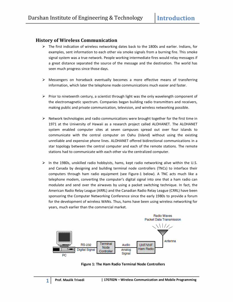
� In the 1980s, unskilled radio hobbyists, hams, kept radio networking alive within the U.S.
and Canada by designing and building terminal node controllers (TNCs) to interface their
computers through ham radio equipment (see Figure-1 below). A TNC acts much like a
telephone modem, converting the computer's digital signal into one that a ham radio can
modulate and send over the airwaves by using a packet switching technique. In fact, the
American Radio Relay League (ARRL) and the Canadian Radio Relay League (CRRL) have been
sponsoring the Computer Networking Conference since the early 1980s to provide a forum
for the development of wireless WANs. Thus, hams have been using wireless networking for
years, much earlier than the commercial market.
Figure 1: The Ham Radio Terminal Node Controllers

Darshan Institute of Engineering & Technology Introduction
2
Prof. Maulik Trivedi | 170702N – Wireless Communication and Mobile Programming
� In 1985, the Federal Communications Commission (FCC) made the commercial development
of radio-based LAN components possible by authorizing the public use of the Industrial,
Scientific, and Medical (ISM) bands. These frequencies reside between 902MHz and
5.85GHz, just above the cellular phone operating frequencies. The ISM band is very
attractive to wireless network vendors because it provides a part of the spectrum upon
which to base their products, and end users do not have to obtain FCC licenses to operate
the products. The ISM band allocation has had a dramatic effect on the wireless industry,
prompting the development of wireless LAN components. Without a standard, though,
vendors began developing proprietary radios and access points.
� The IEEE Standards Board approved the standard on June 26, 1997, and the IEEE published
the standard on November 18, 1997. The finalization of this standard prompted vendors to
release 1Mbps and 2Mbps 802.11-compliant radio cards and access points throughout 1998.
In December 1999, the IEEE released supplements (802.11a and 802.11b) to the 802.11
standard in order to increase performance of wireless LANs up to 54Mbps. Vendors began
shipping wireless LANs operating at 11Mbps throughout 2000 (at prices of less than $200
per radio card) and at 22Mbps starting in 2001. The 54Mbps wireless LANs (IEEE 802.11a-
compliant) will be available toward the end of 2001, slightly ahead of HiperLAN/2 systems.
� Because of falling prices and increasing performance, wireless LANs today are taking on a
much larger role in horizontal enterprise applications. The price and performance of wireless
LANs are getting much closer to traditional wired, Ethernet networks. Prices for wireless LAN
radio cards are expected to decrease by at least 50% during 2001. It's very likely that the
average price for wireless LAN radio cards will match the price of equivalent (performance
and form factor) Ethernet cards as we enter 2002. As a result, an information system
manager is now in a position to give serious consideration to IEEE 802.11 wireless LANs for
supporting high-speed network connections to PC and laptop users within his facilities.
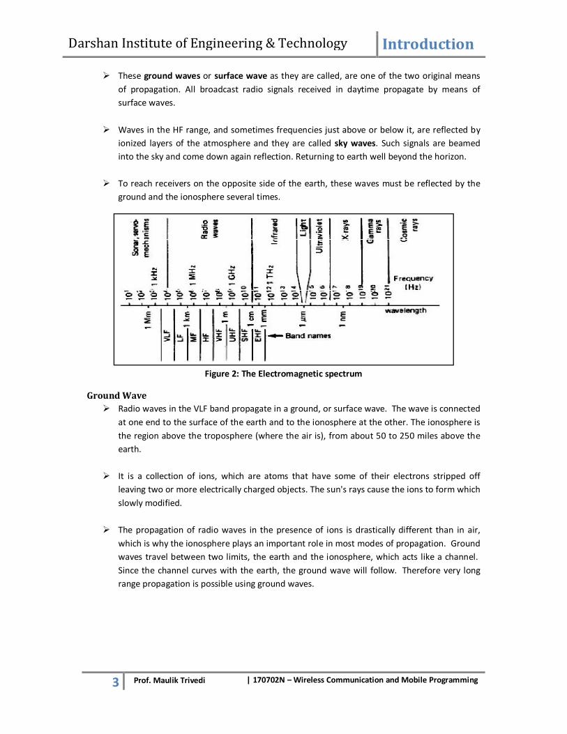
Propagation Modes
� In an earth environment, electromagnetic waves propagate in ways that depend an own
properties but also on those of the environment itself. The various methods of propagation
depends largely on frequency, the complete electromagnetic spectrum is now shown in
figure-2.
� Wave in straight lines, except where the earth and its atmosphere alter their path. Except in
unusual circumstances, frequencies above the HF generally travel in straight lines. They
propagate by means of so called space waves. They are sometimes called tropospheric
waves. Since they travel in the troposphere, the portion of the atmosphere closest to the
ground.
� Frequencies below the HF range travel around the curvature of the earth, sometimes right
around the globe. The means are probably a combination of diffraction and a type of
waveguide effect which uses the earth’s surface and the lowest ionized layer of the
atmosphere as the two waveguide walls.
Darshan Institute of Engineering & Technology Introduction
3 Prof. Maulik Trivedi | 170702N – Wireless Communication and Mobile Programming
� These ground waves or surface wave as they are called, are one of the two original means
of propagation. All broadcast radio signals received in daytime propagate by means of
surface waves.
� Waves in the HF range, and sometimes frequencies just above or below it, are reflected by
ionized layers of the atmosphere and they are called sky waves. Such signals are beamed
into the sky and come down again reflection. Returning to earth well beyond the horizon.
� To reach receivers on the opposite side of the earth, these waves must be reflected by the
ground and the ionosphere several times.
Figure 2: The Electromagnetic spectrum
Ground Wave
� Radio waves in the VLF band propagate in a ground, or surface wave. The wave is connected
at one end to the surface of the earth and to the ionosphere at the other. The ionosphere is
the region above the troposphere (where the air is), from about 50 to 250 miles above the
earth.
� It is a collection of ions, which are atoms that have some of their electrons stripped off
leaving two or more electrically charged objects. The sun's rays cause the ions to form which
slowly modified.
� The propagation of radio waves in the presence of ions is drastically different than in air,
which is why the ionosphere plays an important role in most modes of propagation. Ground
waves travel between two limits, the earth and the ionosphere, which acts like a channel.
Since the channel curves with the earth, the ground wave will follow. Therefore very long
range propagation is possible using ground waves.

Darshan Institute of Engineering & Technology Introduction
4 Prof. Maulik Trivedi | 170702N – Wireless Communication and Mobile Programming
Figure 3: The Ground Wave Propagation
Sky Waves
� Radio waves in the LF and MF ranges may also propagate as ground waves, but suffer
significant losses, or are attenuated, particularly at higher frequencies. But as the ground
wave mode fades out, a new mode develops: the sky wave.
� Sky waves are reflections from the ionosphere. While the wave is in the ionosphere, it is
strongly bent, or refracted, ultimately back to the ground. From a long distance away this
appears as a reflection. Long ranges are possible in this mode also, up to hundreds of miles.
� Sky waves in this frequency band are usually only possible at night, when the concentration
of ions is not too great since the ionosphere also tends to attenuate the signal. However, at
night, there are just enough ions to reflect the wave but not reduce its power too much.
Wireless Network Architecture
In general, networks perform many functions to transfer information from source to destination.
1. The medium provides a bit pipe (path for data to flow) for the transmission of data.
2. Medium access techniques facilitate the sharing of a common medium.
3. Synchronization and error control mechanisms ensure that each link transfers the data
intact.
4. Routing mechanisms move the data from the originating source to the intended destination.
� A good way to depict these functions is to specify the network’s architecture. This
architecture describes the protocols, major hardware, and software elements that
constitute the network. Network architecture, whether wireless or wired, may be viewed in
two ways, logically and physically.
Logical architecture a wireless network
� A logical architecture defines the network’s protocols rules by which two entities
communicate. People observe protocols every day. Individuals participating in a business
meeting, for example, interchange their idea and concerns while they avoid talking at the
same time.

Darshan Institute of Engineering & Technology Introduction
5
Prof. Maulik Trivedi | 170702N – Wireless Communication and Mobile Programming
� They also rephrase a message if no one understands it. Doing so ensures well managed and
effective means of communication. Likewise, PCs, Servers, routers, and other active devices
must conform to very strict rules to facilitate the proper coordination and transformation.
� One popular standard logical architecture is the 7 layer Open System Interconnection (OSI)
Reference Model, developed by the International Standards Organization (ISO). OSI specifies
a complete set of network function, grouped into layers Figure illustrate the OSI Reference
Model.
Figure 4: The Open System Interconnection Reference Model
The OSI layers provide the following network functionality:
Layer 7 - Application layer
Establishment communication with other users and provides services such as file transfer
and email to the end uses of the network.
Layer 6 - Presentation layer
Negotiates data transfer syntax for the application layer and performs translations between
different data types, if necessary.
Layer 5 - Session layer
Establishes manages, and terminates sessions between applications.
Layer 4 - Transport layer
Provides mechanisms for the establishment, maintenance, and orderly termination of virtual circuits,
while shielding the higher layers from the network implementation details.
Layer 3 - Network layer
Provides the routing of packets from source to destination.
Layer 2 - Data Link layer
Ensures synchronization and error control between two entities.
Application
Relay Node
Network
Data Link
Physical
Presentation
Session
Transport
Network
Data Link
Physical
Application
Presentation
Session
Transport
Network
Data Link
Physical
End user-A End user-B

Darshan Institute of Engineering & Technology Introduction
6 Prof. Maulik Trivedi | 170702N – Wireless Communication and Mobile Programming
Layer 1 - Physical layer
Provides the transmission of bits through a communication channel by defining electrical,
mechanical, and procedural specifications.
Figure 5: Wireless Network Logical Architecture
� In figure, wireless LANs and MANs function only within the physical and data link layers,
which provide the medium, link synchronization, and error control mechanisms. Wireless
WANs provide these first two layers, as well as network layer architecture needs to include
function such as end to end connection establishment and application services.
Applications
Vertical industries where mobile technology has already been successfully adopted include
Consumer Goods, Delivery and Rout Sales, Government, Healthcare, Market Research,
Pharmaceuticals, Transportation, and Utilities.
Consumer Goods
� Typical applications include inventory, merchandising, order entry, and sales automation.
Features found in these applications usually provide access to stock and pricing information,
monitor promotions, and perform shelf space analysis including number of facings and
product age. Customer detail helps reps to act more as consultants than order takers.
Delivery & Route Sales
� With fierce competition and an increasing inventory, having timely and accurate information
is more important than ever.
Government
� Applications center on assessments, inspections, and work orders. Most of these
applications involve auditing some sort of facility or process (food service, restaurant,
nursing home, child care, and schools, commercial and residential buildings).
Wireless
Network
Network Layer
Wireless
LANS/MANS
Wireless
WANS
Upper Layer
Protocol
Data Link
Layer
Physical Layer
Upper Layer
Protocol
Network Layer
Data Link
Layer
Physical Layer
User A User B

Darshan Institute of Engineering & Technology Introduction
7
Prof. Maulik Trivedi | 170702N – Wireless Communication and Mobile Programming
Healthcare
� The focus in this industry has been on automating patient records, medication dispensing,
and sample collection. A common goal is to leverage mobile computing in the
implementation of positive patient identification.
Market Research
� Automating the survey process has enabled these companies to get their data more
accurately and quickly while being able to customize their queries at will.
Pharmaceuticals
� In addition to the reps need to perform account management and call reporting functions,
the FDA’s requirement for physician signatures for all drug samples dispensed was an added
complication that was eliminated through the use of mobile technology.
Transportation
� Transforming freight damage inspections from paper to mobile computing greatly expedites
the process and reduces costs by providing on-line pre-shipment inspections. This
technology also offers a more efficient means of storing and transmitting maintenance
inspection reports. In conjunction with GPS (global positioning systems), mobile computing
allows companies to provide better customer service by being continually aware of exactly
where any given shipment is when in transit.
Utilities
� Eliminating the rekeying of data and providing a means to perform on site analysis are
instrumental to an industry that is required to perform inspections on a routine basis.
Business
� Today’s typical travelling salesman needs instant access to the company’s database: to
ensure that files on her laptop reflect the actual state, to enable the company to keep track
of all activities of their travelling employees, to keep database consistent etc. With wireless
access, the laptop can be turned into a true mobile office.
Security
� Security and privacy are of specific concerns in wireless communication because of the ease
of connecting to the wireless link anonymously. Common problems are impersonation,
denial of service and tapping. The main technique used is encryption. In personal profiles of
users are used to restrict access to the mobile units.
Concerns and standards
The benefits of a wireless network are certainly welcomed by companies and organizations. Network
managers and engineers should be aware, however, of the following concerns that surround the
implementation and use of wireless networking:
� Radio signal interference
� Power management

Darshan Institute of Engineering & Technology Introduction
8
Prof. Maulik Trivedi | 170702N – Wireless Communication and Mobile Programming
� System interoperability
� Network security
� Installation issues
� Health risks
Radio Signal Interference
The purpose of radio-based networks is to transmit and receive signals efficiently over airwaves. This
process, though, makes these systems vulnerable to atmospheric noise and transmissions from
other systems. In addition, these wireless networks could interfere with other radio wave
equipment. Interference may be inward or outward.
� Inward Interference
Most of us have experienced radio signal interference while talking on a wireless telephone,
watching television, or listening to a radio. Someone close by might be communicating with
another person via a short-wave radio system, causing harmonic frequencies that you can
hear while listening to your favorite radio station. Or, a remote control car can cause static
on a wireless phone while you are attempting to have a conversation. These types of
interference might also disturb radio-based wireless networks in the form of inward
interference.
� Outward Interference
Inward interference is only half of the problem. The other half of the issue, outward
interference, occurs when a wireless network’s signal disrupts other systems, such as
adjacent wireless LANs, navigation equipment on aircraft, and so on. This disruption results
in the loss of some or all of the system’s functionality. Interference is uncommon with ISM
band products because they operate on such little power. The transmitting components
must be very close and operating in the same bandwidth for either one to experience inward
or outward interference.
Power Management
� If you are using a portable computer in an automobile, performing an inventory in a
warehouse, or caring for patients in a hospital, it might be cumbersome or impossible to
plug your computer into an electrical outlet. Thus, you will be dependent on the computer’s
battery. The extra load of the wireless NIC in this situation can significantly decrease the
amount of time you have available to operate the computer before needing to recharge the
batteries. Your operating time, therefore, might decrease to less than an hour if you access
the network often.
� To counter this problem, vendors implement power management techniques in their
PCMCIA format wireless NICs. Proxim’s wireless LAN product, RangeLAN2/PCMCIA, for
example, maximizes power conservation. RangeLAN2 accommodates advanced power
management features found in most portable computers.
� Without power management, radio-based wireless components normally remain in a
receptive state waiting for any information. Proxim incorporates two modes to help
conserve power: the Doze Mode and the Sleep Mode.

Darshan Institute of Engineering & Technology Introduction
9
Prof. Maulik Trivedi | 170702N – Wireless Communication and Mobile Programming
� The Doze Mode, which is the default state of the product, keeps the radio off most of the
time and wakes up periodically to determine if any messages await in a special mailbox. This
mode alone utilizes approximately 50 percent less battery power.
� The Sleep Mode causes the radio to remain in a transmit-only standby mode. In other words,
the radio wakes up and sends information if necessary, but is not capable of receiving any
information. Other products offer similar power management features.
System Interoperability
� When implementing an Ethernet network, network managers and engineers can deploy NICs
from a variety of vendors on the same network. Because of the stable IEEE 802.3 standard
that specifies the protocols and electrical characteristics that manufacturer must follow for
Ethernet, these products all speak exactly the same language.
� This uniformity allows you to select products meeting your requirements at the lowest cost
from a variety of manufacturers. Today, this is not possible with most wireless network
products, especially wireless LANs and MANs. The selection of these wireless products is
predominantly single vendor, sole-source acquisitions. Products from one vendor will not
interoperate with those from a different company. This raises a problem when deploying the
network.
� Once you decide to buy a particular brand of wireless network component, you must
continue to purchase that brand to ensure that the components can talk the same language
as the existing ones. Putting yourself in this situation is risky.
Benefits
The benefits of automating data collection applications with mobile computing are the reduction of
hard and soft costs, enhancement of revenue potential, and a distinct competitive advantage
through:
� Improving the data collection process
� Improving data accuracy
� Reducing paperwork
� Enforcing collection of more complete information
� Facilitating collection of more useful information
� Eliminating redundant data entry
� Reducing administrative costs
� Reducing billing errors
� Reducing data backlog
� Improving information flow
� Allowing faster adaptation to changing business conditions
� Increasing responsiveness and customer satisfaction
� Providing access to previously unavailable information

Darshan Institute of Engineering & Technology Introduction
10
Prof. Maulik Trivedi | 170702N – Wireless Communication and Mobile Programming
Future
� There's more happening than many people suspect. The difficulty, though, is to provide the
right network, the right device, the right price and the right applications. Wireless is not
wired, and there are numerous advantages and disadvantages. The wireless industry
"mindset" is different from the computer community's. These different philosophies
produce what we call a "wireless-Web culture clash." Also, much of the information we
obtain via the Internet isn't worth paying for in a mobile environment.
� The Internet will change is already changing the way mobile companies and computer
companies offer products and services, and deal with customers. Indeed, many wireless
subscribers will demand these changes, ranging from online customer service to electronic
bill-paying to creating profiles that automatically transmit personalized information via the
Internet to wireless devices.
� We are in a period of tremendous change. Its mobile computing jungle where old
technologies must evolve to survive and where proponents of new technologies are
jockeying for dominance. It is a dangerous and exciting time where existing business models
can crumble and more nimble, innovative companies can usurp established institutions.
Uncovering these developments, analyzing their impact and recommending solutions to
corporations is what Wireless Internet & Mobile Computing consulting is all about.
What Mobile Users Need
Mobile business users need mobile technology that is easy to use and easy to carry with them. They
will not tolerate anything less in their demanding jobs. Mobile workers may be working indoors or
outdoors, have limited access to corporate networks and typically have many interactions with
people and information throughout their workday. Mobile workers need practical mobility, ease of
use, data access, and personalization of data.
Practical mobility
� Devices must be small in many mobile work situations to be useful. Small for most mobile
workers means that the device fits in their mobile devices while they are standing and
without the need to set the device down on a supporting surface. Mobile workers need fast
access to information without having to wait for the device to “boot up”.
Ease of use
� User interfaces have to be designed so that they can be manipulated easily and intuitively
using interaction capabilities such as a stylus drop down lists, and thumb keyboards. Data
collection is a practical mobile computing application as long as it is designed around the
users’ task and minimizes unnecessary data entry, keystrokes and stylus strokes. PDAs
(Personal Digital Assistants such as Palm and PocketPC) and tablet computers are examples
of mobile computing devices that can work effectively for data entry. Today’s phones are
not practical for data collection due to very small displays and cumbersome alpha keys.

Darshan Institute of Engineering & Technology Introduction
11
Prof. Maulik Trivedi | 170702N – Wireless Communication and Mobile Programming
Data access
� Mobile workers require useable information at the point of need. This includes email as a
starting point, but more effectively such as product specifications, services descriptions, and
inventory availability.
Personalization of data
� Mobile users will avoid using devices if they cannot easily obtain the information and only
the relevant information they need. They don’t have the time for extensive searches. Mobile
device screen size limits the amount of information that can be displayed at one time.
Successful mobile technology solution personalize the information for each user and take
advantage of the screen “real estate” that is available on the mobile device.
� For example, information relevant to an upcoming meeting with a customer is presented
based on a customer profile database. Another example is filtering a large catalog based for
a given customer’s needs so that catalog searches are limited to what the customer will
likely order.
Anytime and anywhere capability
� Mobile users need to have solutions that can be used effectively at any time during their
workday and used whenever their work takes them. For example, customer orders should
be entered on the mobile device at the point of need. Having to write down order
information for entry later inefficient and more prone to errors.
AOC and SOC Client
� Mobile technology can be implemented with Sometimes on Connectivity (SOC) to mobile
devices or always on Connectivity (AOC). BSI Consulting coined SOC and AOC terminology in
order to effectively describe to our clients the communications frequency and performance:
capabilities of alternatives for mobile computing solutions. SOC clients can work effectively
in a disconnected mode and take advantage of wireless or wired connections when they are
available while AOC clients must be connected all or most of the time to be effective.
� SOC clients have the ability to store large amounts of data on the mobile device and provide
the user with a complete application solution even when the user does not have a wireless
or wired data connection. Data updates can occur when wireless, Internet dialup, network
or desktop synchronization connections are available. Regardless of connectivity, productive
work can proceed.
� Data updates, when they do occur, can be fast bursts of small amounts of data rather than
entire screen images that AOC clients employ. SOC client technology typically requires a
Pocket PC or WinCE device in order to have sufficient processing power and data storage
capability.
� AOC clients have small amounts of data or no data on board the device. AOC clients require
a wireless connection that is always on to be able to access data and the user interface, or

Darshan Institute of Engineering & Technology Introduction
12
Prof. Maulik Trivedi | 170702N – Wireless Communication and Mobile Programming
screen image. AOC clients typically use a browser for application interactions. Internet-like
HTML or WAP is employed by the browser to view web pages that are especially designed
for the smaller screens of mobile devices. AOC clients require transmission of the data and
screen image for each user action. Consequently, mobile workers need a wireless
connection constantly available in order to effectively use AOC client mobile devices.
Mobile Computing OS
� A mobile operating system, also known as a mobile OS, a mobile platform, or a handheld
operating system, is the operating system that controls a mobile device or information
appliance—similar in principle to an operating system such as Windows, Mac OS, or Linux
that controls a desktop computer or laptop. However, they are currently somewhat simpler,
and deal more with the wireless versions of broadband and local connectivity, mobile
multimedia formats, and different input methods.
� Typical examples of devices running a mobile operating system are smart phones, personal
digital assistants (PDAs), and information appliances, or what are sometimes referred to as
smart devices, which may also include embedded systems, or other mobile devices and
wireless devices.
Symbian OS
� Symbian OS has become a standard operating system for smartphones, and is licensed by
more than 85 percent of the world's handset manufacturers. The Symbian OS is designed for
the specific requirements of 2.5G and 3G mobile phones.
Windows Mobile
� The Windows Mobile platform is available on a variety of devices from a variety of wireless
operators. You will find Windows Mobile software on Dell, HP, Motorola, Palm and i-mate
products. Windows Mobile powered devices are available on GSM or CDMA networks.
Palm OS
� Since the introduction of the first Palm Pilot in 1996, the Palm OS platform has provided
mobile devices with essential business tools, as well as capability to access the Internet or a
central corporate database via a wireless connection.
Mobile Linux:
� The first company to launch phones with Linux as its OS was Motorola in 2003. Linux is seen
as a suitable option for higher-end phones with powerful processors and larger amounts of
memory.
MXI
� MXI is a universal mobile operating system that allows existing full-fledged desktop and
mobile applications written for Windows, Linux, Java, Palm be enabled immediately on
mobile devices without any redevelopment. MXI allows for interoperability between various
platforms, networks, software and hardware components.

(1.) Cellular Telephony
• The concept of cellular telephony evolves during 1970’s. These systems provide a wireless
connection to the PSTN(Public Switch Telephone Network) for any user location within the radio
range of the system. It provides high quality service that in same as landline system.
• High capacity is achieved by limiting the coverage of each BS. Transmitter to a small
geographical area are called cell so the same radio channels may be reused by another BS. A
technique called handoff enables a call to proceed uninterruptedly when the user moves from
one cell to another.
• The basic cellular system consist of mobile station(MS), base station(BS) and mobile switching
centre(MSC). The MSC sometimes called as MTSO(Mobile Telephone Switching Office), it is
responsible for connecting all mobiles to PSTN in a cellular system.
• The MS contains a transceiver, an antenna and control circuit and may be routed in an vehicle or
used as a portable handset. The BS consist of several transmitters and receivers which
simultaneously handle duplex communication and have towers which support several
transmitting and receiving antennas. The BS serves as a bridge between all mobiles users in the
cell and connects the simultaneous mobile cell via telephone line to MSC. The MSC connects the
activities of all the base stations and connects the entire cellular system to the PSTN.
• The standard common air interface(CAI) specifies the communication between BS and MS. The
communication between both the stations can be defined through four different channels:
Forward Voice Channels (FVC)
This channel is used for the transmission of voice from BS to MS.
Reverse Voice Channels (RVC)
This channel is used for the transmission of voice in reverse direction i.e. from MS to
BS.
• Two other channels are also defined for initiating a mobile call named FCC and RCC.
i.e. Forward control channels and Reverse control channels.
• These control channels can also named as setup channels due to their initiation of
calls.
• The generations of cellular telephony systems also includes various other systems
named as AMPS, GSM, IS-136 and IS-95 digital cellular systems.
(2.) Digital European Cordless Telephone(DECT)
• The European Digital Enhance Cordless Telecommunication standard was developed
by ETSI to serve a range of applications that include the following:
1. Residential Systems
2. Small business systems (single site, single cell)
3. Large business systems (multi site, multi cell)
4. Public cordless access systems
5. Wireless Data (LAN) access systems
6. Evolutionary systems

• The DECT standard has a modular structure so that requirements of different
applications can be accommodated in a cost-effective manner. The DECT standard
therefore includes the public access profiles (PAP), a set of specifications to which all
DECT equipment designed for public cordless access must conform.
• The DECT standard can support high local user density and is suitable for operation in unpredictable and highly variable traffic and propagation conditions.
• The data and multimedia capabilities for DECT have recently been enhanced by such
newly developed DECT standards as DECT packets radio service (DRPS) and
multimedia access profile (MMAP).
• A functional or conceptual view for a DECT system is shown in Fig. 1. The DECT
system is composed of a number of functional entities, including the following:
1. The DECT portable handset or terminal: It allows data transmission
faxing etc.
2. The DECT radio fixed part (RFP): It is a part of physical layer interface
of DECT which is used to handle radio frequency channels for
transmission.
3. The Cordless cluster controller (CC): It provides handling of RFP’s
clusters so, that inter cell handoffs can be handled properly.
4. The network specific interface unit (IU): It allows initiation and
cancellation of cells providing required interfaces to connect to PSTN,
ISDN, and GSM etc. It can also be named as networking unit.
5. The mobility management function: It provides different mobility
management operations such as centralized authentication in multi-
location PBX based networks.

Radio Aspects:
• DECT uses a different channel structure for the call setup phase. Though the basic
data are for DECT is 32 kb/s, a number of time slots can be concatenated to provide
higher bit rate channels. Higher capacity channels can be set up in both the simplex
and duplex modes. The DECT standards also defines half-rate channels, which can be
used for deployment of low bit rate codec’s.
• The mechanism for channel selection in DECT is known as continues dynamic
channel selection (CDCS), whereby channels are chosen on the basis of least

interface within all the available DECT channels. When a connection is needed, the
portable selects a channel with least interference, and continues to scan the
remaining channels. If a better channel becomes available during the call, the
portable switches to this channel. The old and new connections can overlap in time,
permitting seamless handoff.
DECT Radio Link
Protocol Architecture
• DECT supports a diverse set of services and applications that requires a clear
distinction between the processes that are part of the DECT specification and those
that the DECT network simply network simply supports. This is turn calls for a
structured protocol architecture based on OSI principles. The DECT protocol
architecture, which follows the OSI layering.
Physical Layer:
The DECT physical layer supports following functions:
• Modulation and demodulation of the radio carriers with the bit stream rates.
• Creation of physical channels with fixed throughputs.
• Monitoring of the radio environment to activate physical channels on request by the
MAC recognize attempts for set up of a physical channel acquire and maintain
synchronization between transmit and receive channels notify the “management
entity” about the status of the physical channel (e.g. quality)
MAC Layer:
• The Primary task of the MAC layer is to allocate radio resources by dynamically
activating and deactivating physical channels and by optimum consideration of the
needs of the associated signaling channels and user information channel(I channel).
• The first function of MAC layer is to support and maintenance of radio bearer by
activating and deactivating physical channels, taking into consideration the changes
in bearer capability and radio resources needed for handoffs.
• The second function of MAC layer is the Multiplexing of the control, information,
paging and broadcast channel onto the physical channel.
• The third function of MAC layer is the segmentation of data frames or data stream
received from the upper layer.
• The last and fourth function of MAC layer protection of data against errors using the
CRC and retransmission if necessary- that is, error protection may not be provided
for user data, depending on the quality requirements for the service.

Data Link Control Layer (DLC)
• The Primary role of data link protocol is to create and maintain reliable connections
between DECT portable and the central system. Separate data link protocols are
defined for the C plane and U plane.
• The C Plane contains two DLC protocols: LB and LAPC (Link Access Procedure for
C Plane). LB offers a connectionless broadcast service and is intended to support
paging of DECT portables for alerting them to incoming calls. LAPC uses variable-
length frames, and its characteristics are matched to the underlying MAC service.
LAPC is used for in-call signaling.
• The data link layer also provides a user plane (U-plane) services which includes:
(a) Null Service: It provides unmodified MAC bearer’s services.
(b) Frame relay service: It allows simple packet transmission.
(c) Frame switching: It allows packets transmission which is time-critical in
nature.
(d) Fully error protected (with FEC) : it provides the services for delay and
error sensitive applications
Network Layer
• The DECT network protocol is defined for the control plane (C plane) only. It provides
the means to request, allocate, manage, and deallocate key resources in the central
system and portable. The capabilities of the DECT system in terms of its flexibility t
support a wide range of applications and interface to diverse network is determined
by the characteristics of the network layer protocols. The techniques used in
designing the network protocol were drawn from the ISDN user-network protocol at
layer-3 and to some extent from the GSM layer 3 protocols. Since, however, the
DECT architecture and requirements differ considerably from both ISDN and GSM,
DECT network layer protocol is significantly different and new. The DECT network
protocol structure is modular and it is intended to support a number of protocol
functions.
(3.) Multiplexing • In mobile computing multiplexing can be viewed as a method by which multiple
analog message signals or digital data streams are combined into one signal over a
shared medium. It can also be called as Muxing. For example, in
telecommunications, several telephone calls may be carried using one wire.
• The multiplexed signal is transmitted over a communication channel, which may be a
physical transmission medium. The multiplexing divides the capacity of the high level
communication channel into several low-level logical channels, one for each message
signal or data stream to be transferred. A reverse process, known as demultiplexing,
can extract the original channels on the receiver side.
• A device that performs the multiplexing is called a multiplexer (MUX) and a device
that performs the reverse process is called a demultiplexer (DEMUX).

• Multiplexer can be of several types:
a. Space-division multiplexing : In wired communication, space-division
multiplexing simply implies different point-to-point wires for different
channels. For example start network, mesh network. While in wireless
communication, space division multiplexing is achieved by multiple antenna
elements forming a phased array antenna.
b. Frequency-division multiplexing: It is an analog technology, FDM achieves
the combining of several digital signals into one medium by sending signals in
several distinct frequency ranges over that medium. One of the most common
applications is cable television. Only one cable reaches a customer’s home but
the service provider can send multiple television channels or signals over that
cable to all subscribers.
c. Time –division multiplexing: It is a digital technology. It involves
sequencing groups of few bits or bytes from each individual input stream, one
after the other, and in such a way that they can be associated with the
appropriate receiver. It should be done such that the receiving device should
not be able to detect that is after a slotted time another logical
communication channel starts to serve the information.
d. Code –division multiplexing: It is also known as spread spectrum. In this
several channels share same frequency. One form is frequency hopping;
another is direct sequence spread spectrum. All channels, each with a
different code, can be transmitted on the same fiber or radio channel or other
medium. Advantages over conventional techniques are that variable
bandwidth is possible.
• Multiplexing can further be extended into multiple access method. It can also be
called as channel access method. It allows several terminals connected to the same
multi-point transmission medium to transmit over it and to share its capacity. Such
as in bus network, hub network, half duplex point to point link.
• Multiplexing is provided by physical layer of OSI model, while multiple accesses also
involved media access control protocol, which is the part of the Data link layer.
• There are different multiple access schemes. Time Division Multiplexing Access
(TDMA), Code Division Multiplexing Access (CDMA), Frequency Division Multiplexing
Access (FDMA). They are used to share the available bandwidth in wireless
communication system.
i. FDMA: It assigns individual channels to individual users. Each user is
allocated a unique frequency band or channel. These channels are
assigned on demand of users who request service. During the period
of the call no other user can share the same channel. In FDD system
the users are assigned channel as a pair of frequencies. One frequency
used for forward channel and other for reverse channel.
ii. TDMA: TDMA can be defined as time division multiplexing which is
used divided the radio spectrum into time slots and in each slot only
one user is allowed to either transmit or receive. TDMA is a technology
used in digital cellular telephone communication that divides each
cellular channel into three time slots in order to increase the amount of
data that can be carried.

iii. CDMA: In this the narrowband message signal is multiplied by a very
large bandwidth signal. This is also known as direct sequence spread
spectrum.
• Application areas using multiplexing includes telephony, telegraphy, analog/digital
data broadcasting and many more.
(4.) Routing in IPv6
• Routing is the process of forwarding packets between connected network segments.
For IPv6-based network, routing is the part of IPv6 that provides forwarding
capabilities between hosts that are located on separate segments within a larger
IPv6 based network.
• IPv6 is the mailroom in which IPv6 data storing and delivery occur. Each incoming or
outgoing packets is called an IPv6 packets.
• An IPv6 packets contains both the source address of the sending host and the
destination address of the receiving host. Unlike, link layer addresses IPv6 addresses
in IPv6 header typically remain the same as the packet travels across an IPv6
network.
• Routing is the primary function of IPv6. IPv6 packets are exchanges and processed
on each host by using IPv6 at each internet layer.
• Above the IPv6 layer, transport services on the source host pass the data inform of
TCP segments or UDP messages down to IPv6 layer. The IPv6 layer creates IPv6
packets with source and destination address information that is used to route the
data through network.
• The IPv6 packets then pass to link layer, where IPv6 packets are converted into
frames for transmitting over network specific media on the physical network. This
process occurs in reverse order on the destination host.
• IPv6 layer services on each sending host examine the destination address of each
packet, compare this address to a locally maintained routing table, and then
determine what additional forwarding is required.
• IPv6 routers are attached to two or more IPv6 network segments that are enabled to
forward packets between them.
IPv6 routers:
• IPv6 network segments, also known as links or subnets, are connected by IPv6
routers, which are devices that pass IPv6 packets from one network segment to
another. This process is known as IPv6 routing and is shown in following figure.

All IPv6 routers have the following characteristics:
• IPv6 routers are physically multi homed hosts.
• A physically multi homed hosts is network host that uses two or more network
connection interfaces to connect to each physically separated network segment.
• IPv6 routers provide packet forwarding for other IPv6 hosts.
• IPv6 routers are distinct from other hosts that use multi-homing. An IPv6 router
must be able to forward IPv6 based communication between networks for other IPv6
network hosts.
Routing Table:
• IPv6 hosts use a routing table to maintain information about other IPv6 network and
IPv6 hosts.
• Network segments are identified by using an IPv6 network prefix and prefix length.
In addition, routing tables provide important information for each local host
regarding how to communicate with each host.
• For each computer on IPv6 network, you can maintain a routing table with an entry
for every other computer that communicates with that local computer.
• Before computer sends an IPv6 packet, it inserts its source IPv6 address and the
destination IPv6 address into IPv6 header.
• The computer then examines IPv6 address, compares it to a locally maintained IPv6
routing table, and takes appropriate action. The computer does one of the three
things:
i. It passes the packets to a protocol layer above IPv6 on local host.
ii. It forward the packet through one of its attached network interfaces.
iii. It discards the packets.
• IPv6 search routing table for route that us closest match to the destination IPv6
address.
• The most specific to the least specific route is determined in the following order:
� A route that matches the destination IPv6 address
� A route that matches the destination with the longest prefix length.
� The default route
• If a matching route is not found, the destination is determined to be an on link
destination.

(5.) GSM Services:
There are three types of services offered through GSM which are:
1.) Telephony (also referred as teleservices) Services
2.) Data (also referred as bearer services) Services
3.) Supplementary Services
Teleservices or Telephony Services
A teleservices utilizes the capabilities of a Bearer Service to transport data, defining which
capabilities are required and how they should setup.
• Voice Calls: The most basic teleservices supported by GSM is telephony. This
includes full rate speech at 13 Kbps and emergency calls, where the nearest
emergency service provider is notified by dialing three digits.
• Videotext and Facsimile: Another group of teleservices includes Videotext access,
Teletext transmission, and Facsimile alternate speech and facsimile Group 3, omatic
facsimile Group 3 etc.
• Short Text Messages: SMS service is a text messaging which allow you to send
and receive text messages on your GSM mobile phones. Services available from
many of the world’s GSM networks today – in addition to simple user generated text
message services – include news, sport, financial, language and location based
services, as well as many early examples of mobile commerce such as stocks and
share prices, mobile banking facilities and leisure booking services.
Bearer Services or Data Services
• Using your GSM phone to receive and send data is the essential building block
leading to widespread mobile Internet access and mobile and mobile data transfer.
GSM currently has a data transfer rate of 9.6k.
• New development that will push up data transfer rated for GSM users are HSCSD are
now available.
Supplementary Services
• Supplementary services are provided on top of teleservices or bearer services, and
include features such as caller identification, call forwarding, call waiting, multi-party
conversation. A brief description of supplementary services is given here:
• Multiparty Service or conferencing: The multiparty service allows a mobile
subscriber to establish multiparty conservations. That is, conservation between three
or more subscribers to setup a conference calls. This service is only applicable to
normal telephony.
• Call Waiting: This service allows a mobile subscriber to be notified of an incoming
call during a conversation. The subscriber can answer, reject or ignore the incoming
call. Call waiting is applicable to all GSM telecommunications services using circuit-
switched connection.

• Call Hold: This service allows a mobile subscriber to put an incoming call on hold
and then resume this call. The call hold service is only applicable to normal
telephony.
• Call Forwarding: The call forwarding supplementary service is used to divert calls
from the original recipient to another number, and is normally set up by the
subscriber himself. It can be used by the subscriber to divert calls from the Mobile
Station when the subscriber is not available, and so to ensure that calls are not lost.
A typical scenario would be a salesperson turns off his mobile phone during a
meeting with customer, but does not wish to lose potential sales leads while he is
unavailable.
• Call Barring: The concept of barring certain type of calls might seem to be a
supplementary disservice rather than service. However, there are times when the
subscriber is not the actual user of the Mobile Station, and as a consequence may
wish to limit its functionality, so as to limit charges incurred. If the subscriber and
users and one and same, the call barring may be useful to stop calls being routed to
international destinations when they are route. The reasons for this are because it is
expected that are roaming subscriber will pay the charges incurred for international
re-routing of calls. So, GSM devised some flexible services that enable the subscriber
to conditionally bar calls.
(6.) Difference between 1G, 2G, 2.5G, 3G and 4G systems:
• 1G: is the first generation cellular network that existed in 1990’s. It transfer data in
analog wave, it has limitation because there are no encryption, the sound quality is
poor and the speed of transfer is only at 9.6 kbps.
• 2G: is the second one, improved by introducing the concept of digital modulation,
which means converting the voice into digital code and then into analog signals.
Being over limitation of 1G, such as it omits the radio power from handsets making
life healthier, and it has enhanced privacy.
• 2.5G: is a transition of 2G and 3G. In 2.5G, the most popular services like SMS,
GPRS, EDGE, High speed circuit switched data and more had been introduced.
• 3G: is the current generation of mobile telecommunication standards, It allows use
of speech and data services and offers data rates of up to 2 mbps, which provide
services like video calls, mobile TV, mobile Internet and downloading. There are
bunch of technologies that fall under 3G, like WCDMA, EV-DO, and HSPA etc.
• 4G: is the fourth generation of cellular wireless standards. It is a successor to the 3G
and 2G families of standards. In 2008, the ITU-R organization specifies the IMT-
Advanced(International Mobile Telecommunication Advanced) requirements for 4G
standards, setting peak speed requirements for 4G service at 100 Mbit/s for high
mobility communication and 1 Gbit/s for low mobility communication.
• 4G system: is expected to provide a comprehensive and secure all-IP based mobile
broadband solution to laptop computer wireless modems, smart phones, and other
mobile devices. Facilities such as ultra-broadband Internet access, IP telephony,
gamin services and streamed multimedia may be provided to users.
• PRE-4G technologies such as mobile WiMax and Long term evolution(LTE) have
been on the market since 2006 and 2009 respectively, and are often branded as 4G.

Wireless LAN
WLAN:
• Make use of a wireless transmission medium
• Typically restricted in their diameter: buildings, campus, single room etc...
• The global goal is to replace office cabling and to introduce high flexibility for ad hoc
communication (e.g. Group meetings)
Wireless LAN advantages:
• Flexibility: within radio coverage, nodes can communicate without further restriction. Radio
waves can penetrate walls.
• Planning: wireless ad hoc networks allow for communication without planning. Wired networks
need wiring plans.
• Robustness: wireless networks can survive disasters, if the wireless devices survive people can
still communicate
Wireless LAN disadvantages
• QoS: WLANs offer typically lower QoS. Lower bandwidth due to limitations in radio transmission
(1- 10 Mbit/s) and higher error rates due to interference
• Cost: Ethernet adapter vs. wireless LAN adapters
• Proprietary solutions: slow standardization procedures lead to many proprietary solutions only
working in an homogeneous environment
• Safety and security: using radio waves for data transmission might interfere with other high-
tech equipment
Wireless LAN: main design goals
• Global operation: LAN equipment may be carried from one country to another and this
operation should be legal (frequency regulations national and international).
• Low power: take into account that devices communicating via WLAN are typically running on
battery power. Special power saving modes and power management functions.
• Simplified spontaneous co-operation: no complicated setup routines but operate
spontaneously after power.
• Easy to use: WLANs are made for simple users; they should not require complex management
but rather work on a plug-and-play basis.
• Protection of investment: a lot of money has been invested for wired LANs; WLANs should be
able to interoperate with existing network (same data type and services).
• Safety and security: safe to operate. Encryption mechanism, do not allow roaming profiles for
tracking people (privacy)
• Transparency for applications: existing applications should continue to work.

Indirect TCP
• Indirect TCP suggests splitting of the TCP layer into two TCP sub
TCPsub-layer between the base
• The BTS has an access point at an agent
packets to and from the MN thro
• TCPm sends and receives the packets to and from the TCP
• The transfer mechanism is simple as there is only
and TCPf is very small. Unlike that
• TCPf layer at the fixed node sends and receives the packets to and from another fixed node TCP
transfer mechanism is standard using multiple hops through the routers.
• The data stream are received from the service access
TCPm .
• Fig(b) shows the handover mechanism . When there is handover when the MN visits a foreign
network, the packets for transmission, buffred at
• On handover, the socket (port an
transfer from TCPm to TCP’m has latency period. (The states of a socket during a TCP connection are
described).
MN1 home
network
TCP
3 4 TCP
2 5 Indirect TCP
1 6
Mobile Station
Node1 (MN1)
Base Transceiver TCP
agent TCPm
Fixed TCPf
Router
(a)
Fixed node TCP’f
8 11 Indirect TCP
Indirect TCP suggests splitting of the TCP layer into two TCP sub-layer. Fig (a). shows the Indirect
layer between the base transceiver (BTS) and the other between the BTS and a FN.
The BTS has an access point at an agent TCPm for TCP connection TCPm sends and receives the
to and from the MN through the BTS. Indirect TCP function in the following manner
sends and receives the packets to and from the TCPf layer at the fixed node.
The transfer mechanism is simple as there is only one hope. Retransmission delay between
is very small. Unlike that between the fixed nodes.
layer at the fixed node sends and receives the packets to and from another fixed node TCP
transfer mechanism is standard using multiple hops through the routers.
The data stream are received from the service access point (application) at the MN and
Fig(b) shows the handover mechanism . When there is handover when the MN visits a foreign
for transmission, buffred at TCPm , are transferred to TCP’m.
(port and IP address) and its present state migrate from TCP, to TCP
has latency period. (The states of a socket during a TCP connection are
Handover
TCP
4 TCP
2 5 Indirect TCP
Base Transceiver TCP
Socket stored packets &
state migration
9 10
7 2
Mobile Station
Node1 (MN1)
Fixed TCPf
Router
Fixed node TCP’
Base Transceiver TCP
agent TCP’m
(b)
8 11 Indirect TCP
. shows the Indirect
BTS) and the other between the BTS and a FN.
sends and receives the
following manner:
layer at the fixed node.
one hope. Retransmission delay between TCPm
layer at the fixed node sends and receives the packets to and from another fixed node TCP’f. The
application) at the MN and buffered at
Fig(b) shows the handover mechanism . When there is handover when the MN visits a foreign
.
d IP address) and its present state migrate from TCP, to TCP’m. The
has latency period. (The states of a socket during a TCP connection are
TCP
10
7 2
Mobile Station
Node1 (MN1)
Fixed node TCP’f
Base Transceiver TCP
m
MN1 foreign
network

MN1 home
network
• Advantage of Indirect TCP: is that mobile part of the network is isolated f
network and thus there is no change in the existing TCP network.
• Disadvantage of Indirect TCP bare the high latency period during handover of packet, possible loss of
the data at the base, and guarantees
• As an example an acknowledgement to a sender may be lost during handover latency.
Selective Repeat Protocol
• Selective Repeat Protocol A modification of the indirect TCP is the selective repeat protocol. Fig
shows a modification in indirect TCP in selective re
MN.
• Between TCPm at the BTS and the MN, the data is selectively repeated using UDP. Between
one end and Tcp’f and TCP’m
conventional fixed-end TCP.
• UDP is a connection-less protocol, therefore, the selective repeat protocol does not guarantee the in
order delivery between the BTS and the MN, unlike TCP.
UDP
3 4 TCP
2 5
1 6
Mobile Station
Node1 (MN1)
Base Transceiver TCP
agent TCPm
Fixed TCP
Router
(a)
Fixed node TCP’
Between the TCPm at BTS &
data is selectively repeated using UDP
8 11 TCP
is that mobile part of the network is isolated from the conventional
there is no change in the existing TCP network.
bare the high latency period during handover of packet, possible loss of
guarantees reliable packet delivery.
an example an acknowledgement to a sender may be lost during handover latency.
Selective Repeat Protocol A modification of the indirect TCP is the selective repeat protocol. Fig
shows a modification in indirect TCP in selective repeat protocol using UDP between the BTS and the
at the BTS and the MN, the data is selectively repeated using UDP. Between
m at the other end, the data stream is transferred, as in case of
less protocol, therefore, the selective repeat protocol does not guarantee the in
between the BTS and the MN, unlike TCP.
Handover
TCP
3 4 TCP
2 5
1 6
Mobile Station
Node1 (MN1)
Base Transceiver TCP
agent TCPm
Fixed TCPf
Socket stored packets &
state migration
9 10
7 2
Mobile Station
Node1 (MN1)
Fixed TCP
Router
Fixed node TCP’
Base Transceiver TCP
agent TCP’m
Fixed node TCP’f
(b)
Between the TCP’m at BTS & MN the
data is selectively repeated using UDP
Between the TCPm at BTS & MN the
data is selectively repeated using UDP
8 11 TCP
rom the conventional
bare the high latency period during handover of packet, possible loss of
an example an acknowledgement to a sender may be lost during handover latency.
Selective Repeat Protocol A modification of the indirect TCP is the selective repeat protocol. Fig
peat protocol using UDP between the BTS and the
at the BTS and the MN, the data is selectively repeated using UDP. Between TCPm at
transferred, as in case of
less protocol, therefore, the selective repeat protocol does not guarantee the in-
UDP
TCP
9 10
7 2
Mobile Station
Node1 (MN1)
Fixed TCPf
Router
Fixed node TCP’f
Base Transceiver TCP
agent TCP’m
Between the TCP’m at BTS & MN the
data is selectively repeated using UDP
MN1 foreign
network

Mobile-end Transport Protocol
• Mobile-end Transport Protocol
protocol. Fig shows the mobile-
• Mobile-end transport protocol guarantees the in
TCP, Between TCPm at the BTS and the MN, the data is transferred by using the mobile
transport protocol.
• Between TCPm at one end and TCP
case of conventional fixed-end TCP.
MOBILE TCP
• Mobile TCP (M-TCP) suggests the splitting of the TCP
to reduce the window size to zero. The TCP split is asymmetric.
• The window is set to zero to prevent the transmission from the TCP transport layer at the MN or the
fixed node, when disconnection is noticed.
• Disconnection is detected when the split connection does not get packets within a timeout interval.
• The window opens again on getting the packet. The M
as it presumes that the packet loss is due to disconnecti
MN1 home
network
TCP
3 4
2 5 TCP
1 6
Mobile Station
Node1 (MN1)
Base Transceiver TCP
agent TCPm
Fixed TCPf
Router
(a)
Fixed node TCP’f
8 11
rotocol
another modification of the indirect TCP is the mobile
-end transport protocol.
end transport protocol guarantees the in-order delivery between the BTS and the MN, like
the BTS and the MN, the data is transferred by using the mobile
at one end and TCPf and TCP’m at the other end, the data stream is transferred, as in
end TCP.
TCP) suggests the splitting of the TCP layer into two TCP sub layer and a mechan
to reduce the window size to zero. The TCP split is asymmetric.
The window is set to zero to prevent the transmission from the TCP transport layer at the MN or the
fixed node, when disconnection is noticed.
Disconnection is detected when the split connection does not get packets within a timeout interval.
The window opens again on getting the packet. The M- TCP host at the base does not use slow start
as it presumes that the packet loss is due to disconnection and not due to conjunction
Handover
TCP
3 4
2 5 TCP
Base Transceiver TCP
Socket stored packets &
state migration
9 10
7 2
Mobile Station
Node1 (MN1)
Fixed TCPf
Router
Fixed node TCP’
Base Transceiver TCP
agent TCP’m
(b)
8 11 TCP
another modification of the indirect TCP is the mobile-end transport
order delivery between the BTS and the MN, like
the BTS and the MN, the data is transferred by using the mobile-end,
at the other end, the data stream is transferred, as in
er into two TCP sub layer and a mechanism
The window is set to zero to prevent the transmission from the TCP transport layer at the MN or the
Disconnection is detected when the split connection does not get packets within a timeout interval.
TCP host at the base does not use slow start
ction interference.
TCP
10
7 2
Mobile Station
Node1 (MN1)
Fixed node TCP’f
Base Transceiver TCP
m
Mobile-end
transport
protocol
MN1 foreign
network

• Data flow control on wireless part of the network is like an on-off control. The window size field is
used for conjunction control during transport the window size field specifies the no. of bites.
• The no. of bites the sender is willing to receive, starting from the acknowledgement field value. In
slow start, the window size is set to one at the beginning and on congestion detection.
• In M- TCP, is set to zero on detection of packet loss or out of reach from the time out or DACK from
the other end.
• The M- TCP supervisory the MN and the BTS and the other between the BTS and the fixed node and
conventional TCP between the fixed node.
• One connection is between the MN and the BTS and other between the BTS and the fixed node. The
BTS has an access point at an agent, SHM for the TCP connection.
• SHM and receives the packets to and from the MN through the BTS. M-TCP functions in the following
manner :
• SHM sends and receives the packets to and from TCPFlayer at the fixed node. The transfer mechanism
is simple.
• There is only one hop retransmission of packets due to DAS between SHM and TCPF does not take
place, unlike the retransmission of packets between the fixed TCP nodes.
• SHM sates the window size to zero in case of time out, as it presumes disconnection of the MN. The
MN or TCPF will also not retransmit as each of them finds that SHM is not receiving packets within the
time out and has set the window to zero.
• When SHM finds that the MN has sent the packet , it presumes that the connectivity is alive again and
sets the window to its old value , i.e. , the value when it last received the packets.
• TCPF layer at a fixed node sends and receives the packets to and from another fixed node TCP-F . The
transfer mechanism is standard , carried out by multiple hops through the routers.
• Error detection and correction is done at the data link or physical layer at the BTS and the MN , not at
SHM .
• The TCP header can be compressed during transmission between SHM and the MN.
• From the service access point (Application) at the MN , data streams are received but not buffered at
SHM and therefore , there is no retransmission from SHM to the MN or to the fixed TCPF layer.
• When there is handover , the packets for transmission are not buffered at SHM and no packets need
to be transferred to SHM. On handover , the socket (port and IP address) and its present state do not
migrate from SHMto SH’M . The SHMto SH’M transfer has not latency period. SHM sets the window size
to zero at the beginning of the handover.SH’M sets to a new window size at the new foreign network.
• The advantages of mobile TCP are – it maintains end to end connection between the base and the
TCP layer at the other end, which guaranties reliable packet delivery and it takes into account
frequent disconnection of the mobile node in a wireless network as the most important factor for
data loss.
• The disadvantages of the mobile TCP are – The mobile part of the network is not isolated from the
conventional because, although there is no change in the existing TCP network.
• The bandwidth changes are frequent due to frequent setting of window size to zero.
• Security risks from the added supervisory hosts, and presumption of low bit error rates in the
wireless network.

Snooping TCP
• The access point snoops into the traffic and buffers packets for fast re-transmission.
• Transparent extension of TCP within the foreign agent.
• Changes of TCP only within the foreign agent.
• Buffering of packets sent to the mobile host.
• Lost packets on the wireless link (both directions!) will be retransmitted immediately by the mobile
host or foreign agent, respectively (so called “local” retransmission).
• The foreign agent therefore “snoops” the packet flow and recognizes acknowledgements in both
directions, it also filters ACKs.
• Data transfer to the mobile host.
• FA buffers data until it receives ACK of the MH, FA detects packet loss via duplicated ACKs or time-out
• Fast retransmission possible, transparent for the fixed network.
• Data transfer from the mobile host.
• FA detects packet loss on the wireless link via sequence numbers, FA answers directly with a NACK to
the MH.
• MH can now retransmit data with only a very short delay.
Advantages:
• End-to-end semantics is preserved.
• Handover is easy. I-TCP requires a careful handover of the system state. Here it falls back to the
standard solution if no enhancements.
Disadvantages:
• Snooping TCP does not isolate the wireless link as good as I-TCP
• Snooping might be useless depending on encryption schemes
• Data is transmitted twice in case of a packet loss. Once from the FA to the MH and the second time
when the ACK finally reaches the CN.

Comparison of different approaches for a “mobile” TCP