dariusz j. pióro* john shepherd jan m. maciejowski · 2 42 d.j. pióro, j. shepherd and j.m....
TRANSCRIPT

240 Int. J. Electric and Hybrid Vehicles, Vol. 2, No. 3, 2010
Simulation and analysis of powertrain hybridisation for construction equipment
Dariusz J. Pióro* J.C. Bamford Excavators Limited Rocester, Staffordshire, ST14 5JP, UK and Department of Engineering University of Cambridge Trumpington Street, Cambridge CB2 1PZ, UK E-mail: [email protected] *Corresponding author
John Shepherd J.C. Bamford Excavators Limited Rocester, Staffordshire, ST14 5JP, UK E-mail: [email protected]
Jan M. Maciejowski Department of Engineering University of Cambridge Trumpington Street, Cambridge CB2 1PZ, UK E-mail: [email protected]
Abstract: Nowadays simulations are widely used in new systems design, and the same approach is applicable to Hybrid Electric Vehicle (HEV) development. In this paper several hybrid powertrain configurations for a typical construction machine – a backhoe loader – are investigated. Roading and lorry-loading performances of the backhoe loader are analysed by means of simulation studies. The simulation tool used for these studies is LMS Imagine.Lab AMESim. Several parameters are analysed, including the machine’s acceleration and top speed, maximum tractive effort, roading performance on a particular test circuit, battery current and state of charge, electric motor and engine power. The results clearly indicate the advantages and disadvantages of each hybrid powertrain configuration.
Keywords: construction equipment; hybrid electric vehicles; HEVs; series hybrid powertrains; parallel hybrid powertrains; split hybrid powertrains; regenerative braking; Advanced Modeling Environment for Performing Simulations; AMESim; simulations.
Reference to this paper should be made as follows: Pióro, D.J., Shepherd, J. and Maciejowski, J.M. (2010) ‘Simulation and analysis of powertrain hybridisation for construction equipment’, Int. J. Electric and Hybrid Vehicles, Vol. 2, No. 3, pp.240–258.
Copyright © 2010 Inderscience Enterprises Ltd.
Simulation and analysis of powertrain hybridisation 241
Biographical notes: Dariusz J. Pióro received his MSc in Mechanical and Power Engineering from Wrocław University of Technology, Wrocław, Poland, in 2002. He is currently participating in a Knowledge Transfer Partnership programme on alternative drive technologies for construction equipment. His research interests include model-based engineering, particularly in the field of alternative propulsion systems, including hybrid electric and hydraulic vehicles, fuel cells and hydrogen.
John Shepherd is an Advanced Systems Manager at JCB Research, UK. He has over 40 years of experience in the design and development of hydraulic systems and their application in aerospace and mobile plants. He has influenced the hydraulics industry and advanced the development of hydraulic components (gear pumps, directional control valves, hoses, hydraulic fluids, cleanliness of systems, etc.) through industry-leading product specifications to meet the demanding applications of off-highway machinery. His primary interest now is the development of energy-efficient systems for off-highway vehicles.
Jan M. Maciejowski is a Professor of Control Engineering and Head of the Information Engineering Division of the Department of Engineering at Cambridge University, UK. He has been President of the Institute of Measurement and Control and of the European Union Control Association. His main research interest is model predictive control and its applications, particularly to autonomous vehicles. He also has a long-standing interest in the modelling of dynamic systems.
1 Introduction
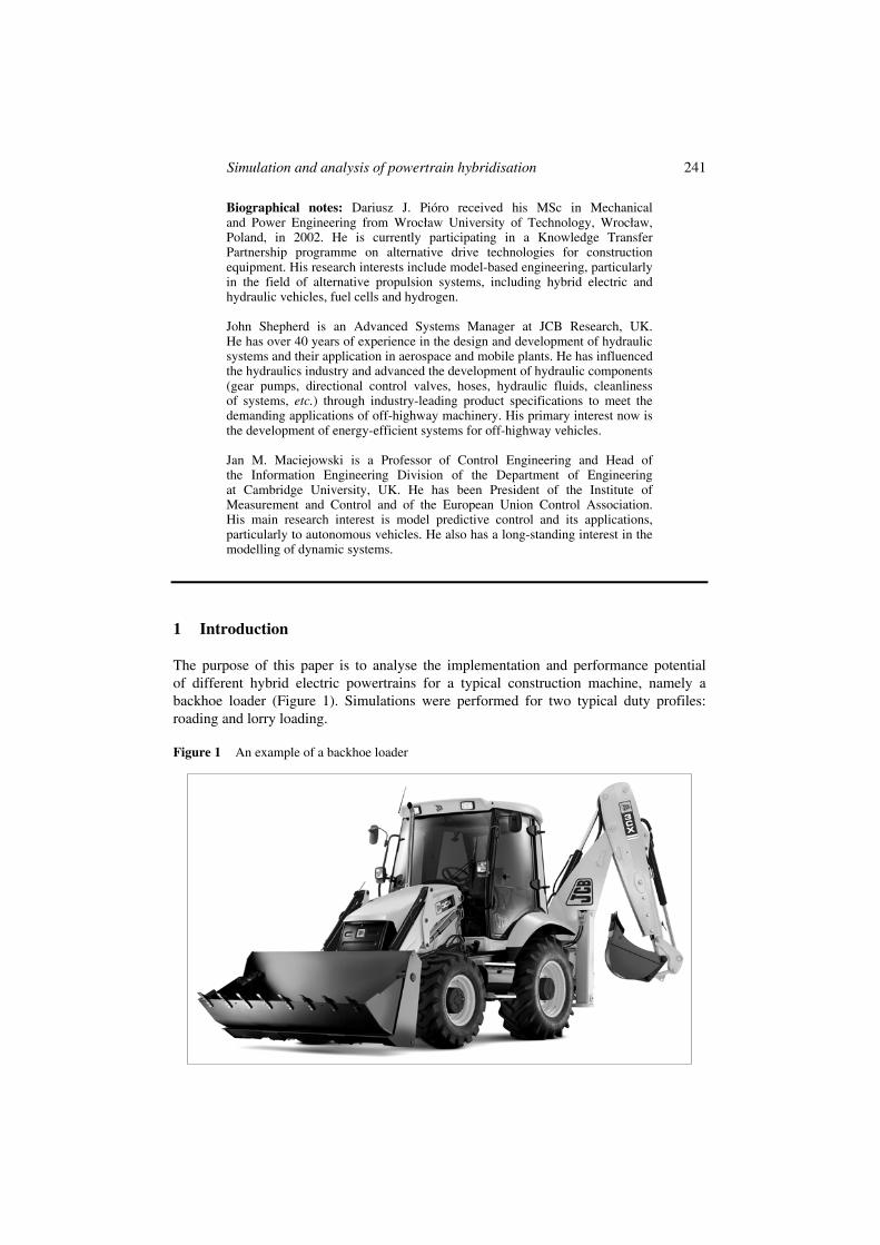
The purpose of this paper is to analyse the implementation and performance potential of different hybrid electric powertrains for a typical construction machine, namely a backhoe loader (Figure 1). Simulations were performed for two typical duty profiles: roading and lorry loading.
Figure 1 An example of a backhoe loader

242 D.J. Pióro, J. Shepherd and J.M. Maciejowski
In order to obtain realistic results from simulation work, a model of a standard backhoe loader was built and validated against actual test data. The high degree of accuracy of this model established confidence in a simulation tool called LMS Imagine.Lab AMESim1 and verified the user’s skills. This approach provided an accurate model of the vehicle, and enabled further modification to accommodate hybrid electric powertrain models.
Next, three basic hybrid electric vehicle architectures (Chau and Wong, 2002) were analysed, with a view to implementation in a backhoe loader: a series hybrid electric, a parallel torque and speed coupling, and a split (series-parallel) powertrain configuration. The scope of this work was to establish the most suitable configuration for a hybrid electric vehicle based on a fixed set of hybrid powertrain components, i.e., an electric generator, motors and battery. In the simulations models of a 120 kW electric generator, 150 kW electric motors and 50 Ah (310 V) battery were used.
2 Simulation and modelling tools
There are many different modelling and simulation software packages available. Some of them, such as MATLAB/Simulink2 and VisSim,3 use the signal port approach, while others, such as SimulationX,4 DYMOLA,5 and LMS Imagine.Lab AMESim,1 are instead based on the multi-port approach.
In the signal port approach, a single value or an array of values is transferred from one component block to another in a single direction. This is fine when causality flows in only one direction, which is the case when ‘information’ is passed from one block to another, with negligible power flow. This is the case, for example, in electronic circuits with high input impedances and low output impedances, if signals are represented by voltages. It is also the case in typical models of control systems.
This is not the case, however, when significant power flows occur between blocks in the model. In this case there are usually two variables involved, often described as an ‘across’ and a ‘through’ variable (or as an ‘effort’ and a ‘flow’), whose product is power. Examples of such (‘across’, ‘through’) pairs are (voltage, current), (speed, force), and (pressure, volumetric flow rate). The multi-port approach supports power flows between blocks by imposing ‘port semantics’ which insist that at connection ports all the ‘effort’ variables are equal, and all the ‘flow’ variables sum to zero (vectorially), thereby enforcing conservation of power. This has several consequences. One convenience is that the system diagram is much closer in appearance to the physical system than is the case with the signal-port approach. A much more fundamental and significant advantage is that it is possible to build up ‘libraries’ of blocks which represent components and subsystems, without knowing what these blocks will be connected to. This allows reuse of library elements, which is the key to reducing modelling costs. This is not possible with the signal-port approach when power flows are involved, because the causality depends on the final interconnection of all the subsystems.
In order to use a signal port approach to model power flows between blocks, two connections must be made between blocks, where physically there is only one. This is because of the requirement to exchange information between blocks in both directions. This leads to great complexity of connections and means that even very simple models involving power transmission appear complex and unnatural.

Simulation and analysis of powertrain hybridisation 243
Detailed explanations of the multi-port approach can be found elsewhere, e.g., Lebrun
and Richards (1997), Karnopp et al. (2006), Cellier (1991) and Wellstead (1979). Note that signal ports can be regarded as a special case of multi-ports (Lebrun et al., 2009).
One of many commercially available software tools for modelling and simulation based on the multi-port approach is AMESim (Advanced Modeling Environment for performing Simulations), available from LMS Imagine. This is the tool chosen by us for the study reported here. AMESim allows the engineer to create very complex models without writing code (Lebrun and Richards, 1997), by using a graphical interface and a library of existing component models. It also allows the user to create new component models and store them in a library, by using a programming language. The user has a choice of either C or Fortran 77 code, and can choose to edit an existing model, or to use a template for a predefined class of models, or to start from scratch. AMESim was initially developed for electro-hydraulic engineering systems with simple one-dimensional mechanical systems (inertias, springs, dampers in translation or rotation, etc.). It progressively developed libraries for a variety of other domains. The component libraries are now organised according to various physical domains, including pneumatic, powertrain, hydraulic, thermal, and electromagnetic. The components, represented by mnemonic icons, can be interconnected exactly like the studied system.
A numerical solver supports Ordinary Differential Equations (ODE) and Differential Algebraic Equations (DAE). The solver automatically switches between various optimised integration algorithms to find the best one for the given model characteristics, such as numerical stiffness, discontinuities, and nonlinearities.
3 Hybrid system configurations
The general classification of hybrid drives is based on the way the engine power is transferred to the wheels. In a series system, the engine power is converted into electricity to drive the traction motors, without any mechanical coupling between the engine and the wheels. In a parallel system, the engine and the electric motor are mechanically parallel coupled and provide power to the wheels so that the wheel torque and speed are proportional to the engine torque and speed. In a series-parallel system, the engine power is split into a mechanical and an electric path so that the engine speed and torque are decoupled from the wheels as in the series system, but a significant share of the engine torque is directly transferred to the wheels through a mechanical connection as in a parallel system (Chau and Wong, 2002).
These powertrain arrangements enable the capture of kinetic energy while braking and therefore improve overall vehicle efficiency. They also allow the engine to be kept working within its most efficient range.
3.1 Series-hybrid system
There are various possible arrangements for a series-hybrid vehicle. For example for a four-wheeled vehicle a series-hybrid powertrain can contain one, two or four electric motors. There is also a need to operate hydraulic actuators to control the machine’s digging and excavating operations. Therefore the hydraulic service system can be propelled by a mechanically or electrically driven pump. In the case of a mechanically

244 D.J. Pióro, J. Shepherd and J.M. Maciejowski
driven pump, it should be a variable displacement pump, as the engine ideally works at a fixed speed in a series-hybrid vehicle. If the pump is propelled by the electric motor, it can be a fixed displacement pump, as the electric motor can feature speed control, which allows flow regulation.
An example of heavy equipment machine implemented with a series-hybrid electric powertrain is a LeTourneau 50-Series mining loader (Letourneau, 2009).
The system analysed in our simulation is shown in Figure 2. The driveline includes an engine, a generator, two electric motors which can act as generators while regenerative braking, two epicyclical single stage gears assembled between each electric motor and a differential gear, front and rear differential gears and a hub gear at each wheel.
Figure 2 A series hybrid electric powertrain layout for a backhoe loader
The electric generator is mounted on a standard diesel engine designed for generating sets. It charges a battery and powers the electric motors that drive the front and rear differential independently.
If the hydraulic service pump is propelled by an electric motor the vehicle can operate in electric-only mode, which can be an advantage, e.g., working in limited noise and emissions areas. If the hydraulic service pump is propelled mechanically the engine must work all the time, although its rotating speed could be adjusted promptly in order to obtain fuel savings and emissions reductions.
3.2 Parallel-hybrid system
It is possible to build different arrangements of parallel-hybrid vehicles. In general one can distinguish between speed-coupling and torque-coupling designs. In the torque-coupling solution the electric motor can be located between the engine and torque converter (pre-torque converter) or between the torque converter and transmission (pre-transmission) or on the output shaft of the transmission (post-transmission). The

Simulation and analysis of powertrain hybridisation 245
speed-coupling configuration is realised by means of proper powertrain arrangement involving an epicycle gear which allows the powers from the engine and the electric motor to be coupled together by coupling their rotation speed.
In this paper the pre-transmission parallel hybrid configuration is analysed. An example of such a powertrain, implemented in a construction vehicle, is the one in the Volvo wheel loader L220F (Volvo Construction Equipment Europe, 2009).
Based on the model of a standard 10-tonne class machine backhoe loader with a 6-speed transmission, a model of the parallel-hybrid electric machine backhoe loader was built. The electric motor was added to the powertrain in such a way as to generate a pre-transmission parallel configuration (Figure 3). Thus the driveline includes the following components: engine, electric motor/generator, torque converter, six-speed transmission, front and rear differential gears and a hub gear at each wheel. The electric motor/generator acts as a motor while accelerating, approaching a pile, and whenever a torque boost is required. The generator function is used when the engine is working with a partial load in order to improve engine efficiency and charge the battery. A generator function is also used while braking and going downhill, instead of engine braking.
Figure 3 A parallel pre-transmission hybrid electric powertrain layout
This configuration can also feature either a mechanical or an electric hydraulic service pump. In the case of a mechanically propelled hydraulic service pump, it is exactly the same pump as it is in a standard machine arrangement.
Conceptually, this design is a mild-hybrid (Karden et al., 2007) with power assistance and regenerative braking features for achieving lower emissions and fuel consumption. In order to allow this architecture to perform as a pure electric vehicle, further development is needed and two clutches must be implemented in such a way as to enable the power to be supplied by the engine alone, by the electric motor alone or by both.
The advantage of the parallel-hybrid powertrain over the series case is that a smaller engine and smaller electric motor can be used to get the same performance.

246 D.J. Pióro, J. Shepherd and J.M. Maciejowski
3.3 Split (series-parallel) hybrid system
In the series-parallel hybrid, the configuration incorporates the features of both the series and parallel HEVs, but involves an additional mechanical link compared with the series-hybrid and also an additional generator compared with the parallel-hybrid. Conceptually this hybrid propulsion system is similar to the hybrid drive system implemented in the Toyota Prius car (Toyota, 2009).
The advantage of this configuration is a downsized engine, for example a reduction from 74 to 56 kW without losing significant performance – see Table 1. On the other hand the complexity and cost of the system is higher than that for a series or parallel configuration.
Table 1 Performance simulation results for different hybrid electric powertrains
Fuel economy Performance
Configuration
Maximum tractive
effort, kN On road km/litre
Lorry loading litres/h
Top speed,
kph Acceleration 0–100 m, sec
Test circuit,
sec
Standard BHL 80.0 2.65 15.35 42.0 17.0 140.5
Series hybrid BHL 86.0 1.56 4.34 37.0 16.6 155.4
Parallel pre-transmission hybrid
82.5 2.88 16.61 42.0 14.0 137.2
Split (series/parallel) hybrid
62.0 2.71 9.53 41.8 16.1 145.15
The modelled driveline is shown in Figure 4 and includes an engine, a planetary gear, two electric motors which can act as generators, a gearbox, a splitting assembly, front and rear differential gears and a hub gear in each wheel. The crankshaft of the engine is mechanically linked with the planetary carrier, the first motor with the ring gear and the second motor with the sun gear. An input of the gearbox is mechanically connected with the sun gear and an output of the gearbox with the splitting assembly, which transfers power directly to the rear axle and via a 4WD clutch to the front axle.
Figure 4 A series-parallel (split) hybrid electric powertrain layout

Simulation and analysis of powertrain hybridisation 247
Both hydraulic pumps are directly connected to the engine via a mechanical shaft; thus the engine must work all the time in order to provide power to the hydraulic power steering. However, a pure electric mode is available within this configuration and can be implemented if electric power steering is used.
4 Subsystem models
4.1 Internal combustion engine
The engine model is arranged in such a way that it provides a torque, depending on the engine speed and the throttle position signal, to the driveline. The output torque is computed as a function of the two inputs defined in a 2D lookup table. The detailed thermodynamic and mass-transport models were not required for the assumed efficiency level.
The engine map includes the ‘engine off’ region in the form of negative torque that is proportional to speed.
Figure 5 Engine output torque versus engine speed for various throttle openings
4.2 Torque converter
The torque converter model used in the simulations is a steady-state torque converter with no dynamics taken into account, as this was found to be sufficiently accurate for the purpose of this study.
The torque converter characteristics are determined by the two curves which are the torque ratio TR and the capacity factor K as functions of the speed ratio SR. Figure 6 shows the characteristics (including efficiency) of a particular torque converter, used in this study.

248 D.J. Pióro, J. Shepherd and J.M. Maciejowski
Figure 6 The torque converter’s efficiency and characteristics
A more detailed description of a torque converter model can be found elsewhere, e.g., Hahn and Lee (2002) and Ohnishi et al. (2000).
4.3 Transmission and axles
A detailed model for the Powershift transmission and axles has been built by means of basic gear, shaft, inertia and clutch blocks available in the standard powertrain and mechanical libraries provided within AMESim. These models were then validated using actual test data in such a way that the power losses which occur in the real transmission and axles are included in the simulation models.
4.4 Electric generator and motors
The models of the electric generator and motors have been built in the MATLAB/ SIMULINK2 environment based on the mathematical model presented by Atallah et al. (1999), Mestha and Evans (1989) and Casanellas (1994). It was possible to use SIMULINK models thanks to the cosimulation interface offered by AMESim. These models determine the losses within a brushless ac permanent magnet machine.
4.5 Battery
A battery model is provided within AMESim and it is an internal resistance type, which characterises the battery by a voltage source and an internal resistance, Figure 7. The simplicity of this model is sufficient for the purposes of our simulations. Further information on this and more advanced battery models can be found elsewhere, e.g., Bejan and Dan (1997) and Johnson (2002).
The battery output voltage V is calculated as follows:
OC INTV V R I= − ⋅
where:
V and VOC = the output and the open circuit voltage respectively
RINT = the equivalent internal resistance in Ω
I = the input current.

Simulation and analysis of powertrain hybridisation 249
Figure 7 Internal resistance battery model
The Depth of Discharge (DOD) is used as an input to read a single cell’s open circuit voltage Vcell and the internal resistance Rcell data, which are stored as 2-D look-up tables. The DOD is expressed in percent and it is computed as:
100_ beg
qDOD DOD
nom capa= ⋅ +
where:
nom_capa = the rated capacity [As]
DODbeg = the DOD at the beginning [%]
q = the charge taken from the battery.
The current through one cell Icell [A] is calculated as:
cellbank
II
P=
where Pbank is the number of battery banks in parallel. The cell output voltage Vcell is calculated as:
cell OC cell cell cellV V R I= − ⋅

250 D.J. Pióro, J. Shepherd and J.M. Maciejowski
where:
VOC cell = one cell’s open circuit voltage
Rcell = one cell’s resistance
Icell = the current through the cell.
The bank output voltage Vbank is deduced as:
bank cell cellV V N= ⋅
where Ncell is the number of cells in series per battery bank. Then the output voltage of the battery V is computed as:
bank bank cell cell bankV V S V N S= ⋅ = ⋅ ⋅
where Sbank is the number of battery banks in series.
4.6 Vehicle and tyres
In order to build a backhoe loader model the vehicle and the tyre blocks available within AMESim’s powertrain library were used. The standard vehicle block has been customised in such a way that it includes rolling resistance dependent on the vehicle speed. This model calculates the longitudinal acceleration, velocity and displacement of the car body based on a mass of vehicle Mcar, drag coefficient Cx, frontal area Avehicle, air density ρair and ambient wind velocity Vair. There is a provision for road slope in percent and computation of the air resistance. No mass transfer is calculated or sent to the tyres as this was not necessary for the accuracy required in this work.
The acceleration is calculated from four longitudinal tyre forces, the ‘slope force’ and the aerodynamic force:
sin arctan100
slopeslope carF M g
α⎛ ⎞⎛ ⎞= ⋅ ⋅ ⎜ ⎟⎜ ⎟⎜ ⎟⎝ ⎠⎝ ⎠
21( )
2aero x air vehicle vehicle vehicleF C A V Vρ= ⋅ ⋅ ⋅ + .
n ).
The total force acting on the vehicle is then:
_ _ _ ta( ) (tot front wheels rear wheels slope aero roll resis ceF F F F F F= + − + +
The tyre model is a simple model of the contact force generation at the tyre/road interface. The force is modelled by a simple tanh function depending on the longitudinal slip. The threshold dSx allows us to specify the slope of the curve at the origin. This model considers the wheel inertia and the tyre force.
The longitudinal slip is calculated as:
.wheel wheel carbodyx
carbody
R VS
V
ϖ⋅ −=

Simulation and analysis of powertrain hybridisation 251
Figure 8 Typical curve of longitudinal force (LMS Imagine.Lab AMESim version 8A)
With this value, the maximum longitudinal force, and the slip threshold, the force can be calculated as:
max
2tanh .x
x xx
SF F
dS
⎛ ⎞⋅= ⋅ ⎜ ⎟
⎝ ⎠
Figure 9 Coefficient of rolling resistance for a typical construction equipment tyre J C Bamford Excavators Ltd6

252 D.J. Pióro, J. Shepherd and J.M. Maciejowski
The power losses within the tyre depend on the coefficient of rolling resistance. The higher coefficient the higher losses. The rolling resistance coefficient characteristic for a typical construction equipment tyre is shown in Figure 9.
4.7 Hydraulic service circuit
The hydraulic service circuit built within this model is very simplified and its main purpose is to reproduce the power demand imposed on the engine while lorry loading or shovelling. The modelled circuit involves the following components: hydraulic pump, pipes and actuator. The mass of boom, arm and handled material is represented by one mass block. In cases of the series and split hybrids a 30 kW electric motor was modelled to propel the hydraulic pump. In case of the parallel hybrid configuration the hydraulic pumps were connected directly to the engine, as in a standard backhoe loader.
5 Duty profiles
The simulated duty profiles were the same as those used to assess the performance of real construction machinery.
5.1 Roading
A backhoe loader’s onroad performance was simulated for a flat road and for a test circuit with different slopes, representing standard working conditions while roading.
For flat road simulations the focus was estimation of the maximum acceleration and top speed. The method of comparing the acceleration for different configurations was to compare the time needed to travel the first 100 metres; this approach is commonly used by off-road vehicle manufacturers as a means of testing existing products.
The focus of the test circuit simulations was to establish fuel consumption and the time needed to perform one flying lap (not standing start).
5.2 Lorry loading
To simulate a typical lorry-loading working profile, the backhoe loader starts at point ‘0’ (see Figure10) and drives towards a pile. It then fills its shovel. Next the machine goes back to the starting point ‘0’, when the operator changes travelling direction without using the brakes, just switching from backward to forward. Then the machine goes forward towards the lorry, where the material collected is deposited, and the operator stops the machine by means of brakes. Finally the machine travels back to the starting point ‘0’.

Simulation and analysis of powertrain hybridisation 253
Figure 10 Illustration of typical lorry loading profile
6 Simulation results
In order to assess the performance of series, parallel and split hybrid electric powertrains several parameters are investigated within the simulation results. These are: time needed to complete the task, vehicle velocity profile, battery state of charge, battery current, electric motor and engine power. In each configuration the design parameters were adjusted so that the simulated performance approximately matched that of a standard backhoe loader. In each case the adjustments were made ‘by hand’ so as to achieve the best trade-off between various aspects of performance.
6.1 Roading
The simulation results clearly show that the parallel-hybrid configuration has the best acceleration and allows the system to be designed in such a way that the electric motor (and therefore the battery too) does not contribute while travelling at top speed on a flat road. The other two configurations feature slightly poorer acceleration and the battery contributes all the time while travelling at top speed, which results in a limited time available to travel at top speed, depending on battery capacity. The series-hybrid offers the poorest acceleration and its top speed is lower than that of a standard machine.
In the case of the split-hybrid powertrain the control algorithm was designed in such a way that for the first period of acceleration the current provided by the generator was greater than the current needed by the motor, which resulted in the battery charging. A similar approach could be implemented within a series-hybrid powertrain, but not with a parallel-hybrid as it has only one electric motor that acts as a generator when needed, and can not boost torque while accelerating and charge the battery at the same time.
The next goal was to establish onroad fuel economy. For this purpose driving through a particular test circuit was simulated. The power flow within each powertrain allows the fuel consumption to be estimated.

254 D.J. Pióro, J. Shepherd and J.M. Maciejowski
The best fuel economy and the shortest one-lap time were obtained for the parallel-hybrid and the worst for the series-hybrid configuration. An explanation of this result can be found in the electric motor’s efficiency at its working point. In the case of the series-hybrid, its electric motors work outside the high efficiency regime while roading at high velocity. For any hybrid configuration investigated in this paper the regenerative braking function allowed the system to recover vehicle kinetic energy while driving down the hill. The performance of the split-hybrid was close to that of a standard machine, but it should be kept in mind that the split-hybrid configuration has a downsized engine.
Figure 11 Vehicle velocity profile for flat road and test circuit duty cycle
Figure 12 Battery state of charge profile for flat road and test circuit duty cycle
Figure 13 Battery current profile for flat road and test circuit duty cycle

Simulation and analysis of powertrain hybridisation 255
Figure 14 Electric motor power profile for flat road and test circuit duty cycle
Figure 15 Engine power profile for flat road and test circuit duty cycle
6.2 Lorry loading
The lorry loading duty cycle is the working profile where the series hybrid shows its advantages over the other configurations, in terms of the tractive effort and fuel economy. The wheels in this configuration are not mechanically connected to the engine, so it is not necessary to spin up the engine in order to generate high torque at the wheels, as it is in other hybrid configurations where a mechanical link between the wheels and the engine exists. However, to obtain high torque at the wheels in the series-hybrid, it is necessary to have high current flowing in the electric motor. High current peaks are covered by the battery and not by the engine, which allows the engine to work with a low power demand and hence relatively low transient periods.
The parallel-hybrid solution offers slightly higher tractive effort and poorer fuel economy over a standard backhoe loader. The regenerative braking process within this configuration is not very effective because, during direction shifting, it is the torque converter which mainly dissipates the vehicle’s kinetic energy. Poor fuel economy is the result of higher energy demand for tractive effort generation than energy recovery by regenerative braking. However this situation could be improved by means of a better control strategy.
The split-hybrid configuration’s tractive effort is lower than for a standard backhoe loader, however roading performance is comparable with the standard configuration. Regenerative braking control is relatively simple for this configuration and improves the overall system efficiency. The engine speed and its power demand are most of the time kept at a constant level so it can operate at the most efficient working point.

256 D.J. Pióro, J. Shepherd and J.M. Maciejowski
Figure 16 Vehicle velocity and battery state of charge profiles for lorry loading duty cycle
Figure 17 Battery current and electric motor power profiles for lorry loading duty cycle
Figure 18 Engine power and distance travelled profiles for lorry loading duty cycle
7 Conclusions
Simulation analysis for various hybrid powertrain configurations in a backhoe loader has been presented in this paper. The simulation results indicate that, among the architectures investigated, there is not a single best solution. All of the analysed configurations have some advantages and disadvantages, which should be considered relative to the anticipated typical working circumstances. If the machine is going to be used mostly in the low speed range, e.g., lorry loading, the simulation results suggest implementation of a series- hybrid configuration, which benefits from the low power demand level imposed on the engine. For roading applications the most suitable configuration would be a

Simulation and analysis of powertrain hybridisation 257
parallel-hybrid, which benefits from regenerative braking and acceleration boost. If the main focus is put only on fuel economy a split-hybrid with a downsized engine is the best option and its overall performance remains close to that of a standard backhoe loader.
Regarding the further development of all these configurations there are several possibilities to choose from. For example the control algorithm can be improved, other types of battery can be used, and/or more efficient electric motors can be selected. Novel components like an ‘electric’ flywheel and/or supercapacitors could be added.
Acknowledgements
The work reported here was done in the context of Knowledge Transfer Partnership 1451 between J C Bamford Excavators Ltd and the University of Cambridge Department of Engineering, supported by the UK’s Technology Strategy Board.
References Atallah, K., Mellor, P.H., Howe, D. and Stone, D.A. (1999) Influence of Gear Change on
the Energy Efficiency of a Gasoline ICE Engine and Integrated Permanent Magnet Motor/Generator Parallel Hybrid Power-Train, Department of Electronic & Electrical Engineering, University of Sheffield, Private communication.
Bejan, A. and Dan, N. (1997) ‘Maximum work from an electric battery model’, Energy, Vol. 22, No. 1, pp.93–102.
Casanellas, F. (1994) ‘Losses in PWM inverters using IGBTs’, IEE Proc. Electrical Power Applications, Vol. 141, No. 5, pp.235–239.
Cellier, F.E. (1991) Continuous System Modeling, New York: Springer-Verlag.
Chau, K.T. and Wong, Y.S. (2002) ‘Overview of power management in hybrid electric vehicles’, Energy Conversion and Management, Vol. 43, pp.1953–1968.
Hahn, J.O. and Lee, K.I. (2002) ‘Nonlinear robust control of torque converter clutch slip system for passenger vehicles using advanced torque estimation algorithms’, Vehicle System Dynamics, Vol. 37, No. 3, pp.175–192.
Johnson, V.H. (2002) ‘Battery performance models in ADVISOR’, Journal of Power Sources, No. 110, pp.321–329.
Karden, E., Ploumen, S., Fricke, B., Miller, T. and Snyder, K. (2007) ‘Energy storage devices for future hybrid electric vehicles’, Journal of Power Sources, No. 168, pp.2–11.
Karnopp, D., Margolis, D.L. and Rosenberg, R.C. (2006) System Dynamics: Modeling and Simulation of Mechatronic Systems, John Wiley & Sons Inc.
Lebrun, M. and Richards, C.W. (1997) ‘How to create good models without writing a single line of code’, Paper presented at the 5th Scandinavian International Conference on Fluid Power, Linköping, Sweden, 28 May.
Lebrun, M., Vasiliu, D. and Vasiliu, N. (2009) ‘Numerical simulation of the fluid control systems by AMESim’, Studies in Informatics and Control, Vol. 18, No. 2.
Letourneau (2009) www.letourneau-inc.com/mining/features.htm.
Mestha, L.K. and Evans, P.D. (1989) ‘Analysis of on-state losses in PWM inverters’, IEE Proc. Electrical Power Applications, Vol. 136, No. 4, pp.189–195.
Ohnishi, H., Ishii, J., Kayano, M. and Katayama, H. (2000) ‘A study on road slope estimation for automatic transmission control’, JSAE Review, No. 21, pp.235–240.

258 D.J. Pióro, J. Shepherd and J.M. Maciejowski
Toyota (2009) www.hybridsynergydrive.com.
Volvo Construction Equipment Europe (2009) www.volvo.com/constructionequipment/europe/ en-gb/environment/hybripower/hybripower.htm.
Wellstead, P.E. (1979) Introduction to Physical System Modelling, London: Academic Press.
Notes
1 LMS Imagine.Lab AMESim, http://www.lmsintl.com/imagine-amesim-intro.
2 The MathWorks, Matlab/Simulink, www.mathworks.com/products/simulink.
3 Visual Solutions, www.vissim.us.
4 ITI, www.iti.de/cms/en/simulationx.html.
5 3DS, http://www.3ds.com/products/catia/portfolio/dymola/overview.
6 J C Bamford Excavators Ltd. Tyre drag test measurements (2005), private communication.