daniel senior orifice fitting 2-16 -...
TRANSCRIPT

Owner and operator manualP/N 3-9008-001, Rev N
January 2016
Daniel ™ Senior Orifice Fitting 2"-16"
2"- 16" 150-1500 / 2"-12" 2500

Daniel customer service
Location Telephone number Fax number
North America/Latin America +1.713.467.6000 +1.713.827.4805
Daniel Customer Service +1.713.827.6314 +1.713.827.6312
USA (toll free) +1.888.356.9001 +1.713.827.3380
Asia Pacific (Republic of Singapore) +65.6777.8211 +65.6777.0947.0743
Europe (Stirling Scotland, UK) +44 (0)1786.433400 +44 (0)1786.433401
Middle East Africa (Dubai, UAE) +971 4 8118100 +971 4 8865465
Daniel Measurement and Control, Inc. (Headquarters)
11100 Brittmoore Park Drive
Houston, TX 77041 USA
http://www.daniel.com
• Customer Service: [email protected]
• Customer Support: [email protected]
• Asia-Pacific: [email protected]
• Europe: [email protected]
Return Material Authorization (RMA)
A Return Material Authorization (RMA) number must be obtained prior to returning any equipment for any reason. Download the
RMA form from the Support Services web page by selecting the link below.
http://www2.emersonprocess.com/EN-US/BRANDS/DANIEL/SUPPORT-SERVICES/Pages/Support-Services.aspx

Signal words and symbols
Pay special attention to the following signal words, safety alert symbols and statements:
Safety alert symbol
This is a safety alert symbol. It is used to alert you to potential physical injury hazards. Obey all safety messages that follow this symbol
to avoid possible injury or death.
DANGER!Danger indicates a hazardous situation which, if not avoided, will result in death or serious injury.
WARNING!Warning indicates a hazardous situation which, if not avoided, could result in death or serious injury.
CAUTION!Caution indicates a hazardous situation which, if not avoided, could result in minor or moderate injury.
NOTICENotice is used to address safety messages or practices not related to personal injury.
ImportantImportant is a statement the user needs to know and consider.
TipTip provides information or suggestions for improved efficiency or best results.
NoteNote is “general by-the-way” content not essential to the main flow of information.

Important safety instructions
Daniel Measurement and Control, Inc. (Daniel) designs, manufactures and tests products to function within specific conditions.Because these products are sophisticated technical instruments, it is important that the owner and operation personnel muststrictly adhere both to the information printed on the product and to all instructions provided in this manual prior to installation,operation, and maintenance.
Daniel also urges you to integrate this manual into your training and safety program.
BE SURE ALL PERSONNEL READ AND FOLLOW THE INSTRUCTIONS IN THIS MANUAL AND ALL NOTICES AND PRODUCT WARNINGS.
WARNING!Failure to follow the installation, operation or maintenance instructions for a Daniel product could lead to serious injury or deathfrom explosion or exposure to dangerous substances.
To reduce the risk:
• Comply with all information on the product, in this manual, and in any local and national codes that apply to this product.
• Do not allow untrained personnel to work with this product.
• Use Daniel parts and work procedures specified in this manual.
Product owners (Purchasers):
• Use the correct product for the environment and pressures present. See technical data or product specifications forlimitations. If you are unsure, discuss your needs with your Daniel representative.
• Inform and train all personnel in the proper installation, operation, and maintenance of this product.
• To ensure safe and proper performance, only informed and trained personnel should install, operate, repair and maintainthis product.
• Verify that this is the correct instruction manual for your Daniel product. If this is not the correct documentation, contactDaniel at 1-713-827-6314. You may also download the correct manual from: http://www.daniel.com.
• Save this instruction manual for future reference.
• If you resell or transfer this product, it is your responsibility to forward this instruction manual along with the product to thenew owner or transferee.
• ALWAYS READ AND FOLLOW THE INSTALLATION, OPERATIONS, MAINTENANCE AND TROUBLESHOOTING MANUAL(S) ANDALL PRODUCT WARNINGS AND INSTRUCTIONS.
• Do not use this equipment for any purpose other than its intended service. This may result in property damage and/orserious personal injury or death.

Product operation (Personnel):
• To prevent personal injury, personnel must follow all instructions of this manual prior to and during operation of theproduct.
• Follow all warnings, cautions, and notices marked on, and supplied with, this product.
• System should be designed to avoid over pressure conditions or exceeding maximum safe flow rate if meter lossesmeasurement.
• Verify that this is the correct instruction manual for your Daniel product. If this is not the correct documentation, contactDaniel at 1-713-827-6314. You may also download the correct manual from: http://www.daniel.com.
• Read and understand all instructions and operating procedures for this product.
• If you do not understand an instruction, or do not feel comfortable following the instructions, contact your Danielrepresentative for clarification or assistance.
• Install this product as specified in the INSTALLATION section of this manual per applicable local and national codes.
• Follow all instructions during the installation, operation, and maintenance of this product.
• Connect the product to the appropriate pressure and electrical sources when and where applicable. Never operate meterabove the maximum working pressure stated on the nameplate.
• Ensure that all connections to pressure and electrical sources are secure prior to and during equipment operation.
• Use only replacement parts specified by Daniel. Unauthorized parts and procedures can affect this product's performance,safety, and invalidate the warranty. “Look-a-like” substitutions may result in deadly fire, explosion, release of toxicsubstances or improper operation.
• Save this instruction manual for future reference.

Notice
THE CONTENTS OF THIS PUBLICATION ARE PRESENTED FOR INFORMATIONAL PURPOSES ONLY, AND WHILE EVERY EFFORT HASBEEN MADE TO ENSURE THEIR ACCURACY, THEY ARE NOT TO BE CONSTRUED AS WARRANTIES OR GUARANTEES, EXPRESSED ORIMPLIED, REGARDING THE PRODUCTS OR SERVICES DESCRIBED HEREIN OR THEIR USE OR APPLICABILITY. ALL SALES ARE GOVERNEDBY DANIEL'S TERMS AND CONDITIONS, WHICH ARE AVAILABLE UPON REQUEST. WE RESERVE THE RIGHT TO MODIFY OR IMPROVETHE DESIGNS OR SPECIFICATIONS OF SUCH PRODUCTS AT ANY TIME.
DANIEL DOES NOT ASSUME RESPONSIBILITY FOR THE SELECTION, USE OR MAINTENANCE OF ANY PRODUCT. RESPONSIBILITY FORPROPER SELECTION, USE AND MAINTENANCE OF ANY DANIEL PRODUCT REMAINS SOLELY WITH THE PURCHASER AND END-USER.
TO THE BEST OF DANIEL'S KNOWLEDGE THE INFORMATION HEREIN IS COMPLETE AND ACCURATE. DANIEL MAKES NOWARRANTIES, EXPRESSED OR IMPLIED, INCLUDING THE IMPLIED WARRANTIES OF MERCHANTABILITY AND FITNESS FOR APARTICULAR PURPOSE WITH RESPECT TO THIS MANUAL AND, IN NO EVENT, SHALL DANIEL BE LIABLE FOR ANY INCIDENTAL,PUNITIVE, SPECIAL OR CONSEQUENTIAL DAMAGES INCLUDING, BUT NOT LIMITED TO, LOSS OF PRODUCTION, LOSS OF PROFITS,LOSS OF REVENUE OR USE AND COSTS INCURRED INCLUDING WITHOUT LIMITATION FOR CAPITAL, FUEL AND POWER, AND CLAIMSOF THIRD PARTIES.
PRODUCT NAMES USED HEREIN ARE FOR MANUFACTURER OR SUPPLIER IDENTIFICATION ONLY AND MAY BE TRADEMARKS/REGISTERED TRADEMARKS OF THESE COMPANIES.

Warranty and Limitations
1. LIMITED WARRANTY: Subject to the limitations contained in Section 2 herein, Daniel Measurement & Control, Inc. (“Daniel”)warrants that the licensed firmware embodied in the Goods will execute the programming instructions provided by Daniel, and thatthe Goods manufactured by Daniel will be free from defects in materials or workmanship under normal use and care and Serviceswill be performed by trained personnel using proper equipment and instrumentation for the particular Service provided. Theforegoing warranties will apply until the expiration of the applicable warranty period. Goods are warranted for twelve (12) monthsfrom the date of initial installation or eighteen (18) months from the date of shipment by Daniel, whichever period expires first.Consumables and Services are warranted for a period of 90 days from the date of shipment or completion of the Services. Productspurchased by Daniel from a third party for resale to Buyer (“Resale Products”) shall carry only the warranty extended by the originalmanufacturer. Buyer agrees that Daniel has no liability for Resale Products beyond making a reasonable commercial effort toarrange for procurement and shipping of the Resale Products. If Buyer discovers any warranty defects and notifies Daniel thereof inwriting during the applicable warranty period, Daniel shall, at its option, correct any errors that are found by Daniel in the firmwareor Services or repair or replace F.O.B. point of manufacture that portion of the Goods or firmware found by Daniel to be defective, orrefund the purchase price of the defective portion of the Goods/Services. All replacements or repairs necessitated by inadequatemaintenance, normal wear and usage, unsuitable power sources or environmental conditions, accident, misuse, improperinstallation, modification, repair, use of unauthorized replacement parts, storage or handling, or any other cause not the fault ofDaniel are not covered by this limited warranty, and shall be at Buyer's expense. Daniel shall not be obligated to pay any costs orcharges incurred by Buyer or any other party except as may be agreed upon in writing in advance by Daniel. All costs of dismantling,reinstallation and freight and the time and expenses of Daniel's personnel and representatives for site travel and diagnosis underthis warranty clause shall be borne by Buyer unless accepted in writing by Daniel. Goods repaired and parts replaced by Danielduring the warranty period shall be in warranty for the remainder of the original warranty period or ninety (90) days, whichever islonger. This limited warranty is the only warranty made by Daniel and can be amended only in a writing signed by Daniel. THEWARRANTIES AND REMEDIES SET FORTH ABOVE ARE EXCLUSIVE. THERE ARE NO REPRESENTATIONS OR WARRANTIES OF ANYKIND, EXPRESS OR IMPLIED, AS TO MERCHANTABILITY, FITNESS FOR PARTICULAR PURPOSE OR ANY OTHER MATTER WITH RESPECTTO ANY OF THE GOODS OR SERVICES. Buyer acknowledges and agrees that corrosion or erosion of materials is not covered by thiswarranty.
2. LIMITATION OF REMEDY AND LIABILITY: Daniel shall not be liable for damages caused by delay in performance. The remedies ofBuyer set forth in this agreement are exclusive. In no event, regardless of the form of the claim or cause of action (whether based incontract, infringement, negligence, strict liability, other tort or otherwise), shall Daniel's liability to Buyer and/or its customersexceed the price to Buyer of the specific goods manufactured or services provided by Daniel giving rise to the claim or cause ofaction. Buyer agrees that in no event shall Daniel's liability to Buyer and/or its customers extend to include incidental, consequentialor punitive damages. The term “consequential damages” shall include, but not be limited to, loss of anticipated profits, revenue oruse and costs incurred including without limitation for capital, fuel and power, and claims of Buyer's customers.


Contents
Part I PlanChapter 1 Introduction ..................................................................................................................3
1.1 Definition of Acronyms ............................................................................................................... 31.2 Purpose of this manual ................................................................................................................41.3 Product description .................................................................................................................... 41.4 Conditions and specifications ..................................................................................................... 61.5 Parts lists .................................................................................................................................... 9
1.5.1 Trim options .................................................................................................................91.5.2 Daniel Senior Orifice Fitting sizes 2"- 8" 150-900 ......................................................... 111.5.3 Daniel Senior Orifice Fitting sizes 10"-16" 150-900 ......................................................191.5.4 Daniel Senior Orifice Fitting sizes 2"-8" 1500 and 2"-6" 2500 ....................................... 241.5.5 Daniel Senior Orifice Fitting sizes 10"- 16" 1500 .......................................................... 291.5.6 Daniel Senior Orifice Fitting sizes 8"-12" 2500 .............................................................34
Part II InstallChapter 2 General Information .................................................................................................... 41
2.1 Installation ................................................................................................................................412.1.1 Information prior to installation ................................................................................. 412.1.2 Storage ...................................................................................................................... 432.1.3 Preliminary Steps ....................................................................................................... 432.1.4 Severe service conditions ........................................................................................... 432.1.5 Corrosive service ........................................................................................................ 442.1.6 Low temperature service ............................................................................................442.1.7 Design considerations ................................................................................................ 452.1.8 Installation configurations ..........................................................................................46
Part III OperateChapter 3 Commissioning ........................................................................................................... 51
3.1 Commission the Daniel Senior Orifice Fitting installation ......................................................... 513.2 Commission the line pressure test ............................................................................................ 533.3 Orifice Plate Installation ............................................................................................................ 55
Part IV MaintainChapter 4 Normal conditions .......................................................................................................63
4.1 Maintenance .............................................................................................................................634.1.1 Recommendations for lubrication .............................................................................. 634.1.2 Lubrication .................................................................................................................634.1.3 Component exercise .................................................................................................. 65
4.2 Orifice plate installation and removal instructions .................................................................... 68
Contents
Owner and operator manual i

4.2.1 Plate change procedure overview ...............................................................................684.2.2 Selecting an appropriate plate change procedure ...................................................... 704.2.3 Orifice plate (13) change operation ............................................................................72
Chapter 5 Supplemental information ........................................................................................ 1455.1 Recommended spare parts for a one-year operation ...............................................................1455.2 Lubricant information ............................................................................................................. 1465.3 Torque information ................................................................................................................ 150
Contents
ii Senior Orifice Fitting

Part IPlan
Plan
Owner and operator manual 1

Plan
2 Senior Orifice Fitting

1 IntroductionTopics covered in this chapter:
• Definition of Acronyms
• Purpose of this manual
• Product description
• Conditions and specifications
• Parts lists
1.1 Definition of Acronyms
Acronyms and their definitionTable 1-1:
Acronym Description
AGA American Gas Association
AISI American Iron and Steel Institute
API American Petroleum Institute
ANSI American National Standards Institute
ASME American Society of Mechanical Engineers
ASTM American Society of Testing and Materials
GPA Gas Processors Association
ISO International Organization of Standards
MSS Manufacturers Standardization Society of the Valve and Fittings Indus-try, Inc
NACE NACE International (formerly National Association of Corrosion Engi-neers)
MPMS API Manual of Petroleum Measurement Standards
API-14.3 API-AGA joint flow measurement code (API MPMS Chapter 14, Section3, Part 2:2000(R2011) - also AGA Report No. 3, Part 2 and GPA8185-00, Part 2)
ISO 5167 ISO flow measurement code (ISO 5167-2:2003(E))
U/S upstream
D/S downstream
DP differential pressure (ΔP) - differences of static pressures found on theU/S and D/S faces of an orifice plate during the flow measurementprocess
CRS cold rolled steel
CS carbon steel
Introduction
Owner and operator manual 3

Acronyms and their definition (continued)Table 1-1:
Acronym Description
SS stainless steel
YP gold (yellow chromate) zinc plated
ZP silver (clear chromate) zinc plated
MAOP maximum allowable operating pressure
NPSM national pipe straight mechanical thread
NPT national pipe tapered thread
HBR butadiene rubber
HNBR hydrogenated nitrile-butadiene rubber
NBR nitrile-butadiene rubber
FFKM perfluoroelastomer rubber
FKM fluoroelastomer rubber
PTFE polytetrafluoroethylene
SBR styrene-butadiene rubber
TFE tetrafluoroehtylene
1.2 Purpose of this manualDaniel Measurement and Control, Inc. designed this manual to guide owners andpersonnel in the installation, operation and maintenance of the Daniel™ Senior™ OrificeFitting.
To ensure safe and proper installation, operation and maintenance, it is imperative thatproduct owners and operation personnel read and follow the information contained in thismanual.
1.3 Product descriptionThe Daniel Senior Orifice Fitting is an orifice plate holding device that houses, andaccurately positions, an orifice plate within a pipe or tube to measure fluid flow. It is onecomponent of a flow measurement system. Daniel designed the Senior Orifice Fitting(Senior) to:
• Position an orifice plate, concentric to flow moving through a pipeline, within API-14.3, Part 2 or ISO 5167 installation requirements.
• Allow personnel to remove and replace an orifice plate without disturbing the flowmeasurement system piping, with little, or no, interruption in service and withoutremoving the Senior from the system.
Introduction
4 Senior Orifice Fitting

The orifice plate within a Senior restricts the fluid moving through a pipe. This restrictioncreates a change in static pipe pressure of the fluid. Instrumentation measure thedifference in change of the fluid entering orifice plate bore, and once again after it exits theplate bore. This instrumentation then combines that information, along with other datagathered from the flowing fluid, and calculates the amount of fluid that passes throughthe system.
The first chamber, or Body (4), properly positions the orifice plate in the flow stream. Thesecond chamber, or Top (14), is a temporary holding place for the orifice plate duringremoving or installing operations (Refer to Section 4.2)
ImportantThe unit components have part numbers assigned on appropriate drawings and tables. Refer to Figure 1-2 thru Figure 1-5 and Table 1-4 thru Table 1-8 for part numbers. Example: Body (4).
Daniel Senior Orifice Fitting - Flangnek™ optionFigure 1-1:
Introduction
Owner and operator manual 5

Therefore, using a Senior may eliminate the need for bypass piping, valves, and otherfittings necessary with conventional orifice fitting installations. Maintenance technicianscan replace and repair all parts of the Senior, including the slide valve assembly, withoutremoving the Body (4) from the line (refer to Section 4.1).
Daniel designs and manufactures all Senior units to applicable API-14.3 recommendationsand in accordance with selected ANSI, ASME and ASTM specifications. As an option, Danielalso designs and manufactures fittings in compliance with ISO 5167.
Products bearing the "CE" mark are designed and manufactured in compliance with theEuropean Union Pressure Equipment Directive (PED) 97/23/EC (available on the internet).
Refer to the "Daniel Orifice Fittings Installation and Operating Instructions specific to thePressure Equipment Directive", Part Number 3-9008-002 (available on the Daniel website).
White papers (available on the Daniel website):
• Upp, E.L. "Application of the Orifice Meter for Accurate Gas Flow Measurement":Daniel Measurement and Control Inc., Houston, Texas USA (1995)
• Upp, E.L. "Development of Orifice Meter Standards": Daniel Measurement andControl Inc., Houston, Texas USA (1995)
• Daniel Measurement and Control Inc. "Fundamentals of Orifice MeterMeasurement": Daniel Measurement and Control Inc., Houston, Texas USA (1997)
• Kendrick, Ray. Effects of the Latest Revision of ANSI/API 2530/AGA 3 On OrificeMeter Primary Elements" Daniel Measurement and Control Inc., Houston, Texas USA(1997)
• Daniel Measurement and Control Inc. "Getting the Best Value From Daniel SeniorOrifice Fittings": Daniel Measurement and Control Inc., Houston, Texas USA (1997)
• Cotton, Galen M. "Pulsation Effects on Gas Measurement": Daniel Measurement andControl Inc., Houston, Texas USA (1980)
• Husain, Zaki D. "Theoretical Uncertainty of Orifice Flow Measurement": DanielMeasurement and Control Inc., Houston, Texas USA (1990)
• Daniel Measurement and Control Inc. "Senior Orifice Fitting Technical Guide: DAN-DIF- TG11-1003 "Daniel Measurement and Control Inc., Houston, Texas USA (2003).
1.4 Conditions and specifications
NOTICE
Follow all the safety and equipment limits recommended in Section 1.4 of this manual.
It is the owner's and/or purchaser's responsibility to comply with these parameters.
Introduction
6 Senior Orifice Fitting
WARNING!
PERSONAL PROTECTION HAZARDFollow all parameters for the Senior Orifice indicated below.
Failure to comply may result in death and serious injury or equipment damage.
Conditions and specificationsTable 1-2:
Product parameters and limitations:
Fluid static pres-sures
Refer to ASME/ANSI B16 standards, and your fitting's material of construction,to determine the maximum operating temperature and pressure of your Se-nior. Daniel provides both the fitting's materials of construction and ASME/AN-SI ratings information on the product nameplate.
Fluid phases: Gas, liquid, vapor
Fluids measured: Most fluids
Fluid temperatureparameters:
-20° F (-29° C) to +100° F (+38° C) is the fluid temperature range for this prod-uct based upon the materials of construction (Refer to ASME codes (1)).
Consult factory before operating this product outside of the specified temper-ature range.
Temperature andoperating pres-sure limitations ofOrifice Plate Sealmaterials:
-20° F (-29° C) to +100° F (+38° C) is the fluid temperature range for this prod-uct based upon the materials of construction (Refer to ASME codes (1)) .
The following list describes the most common Orifice Plate Seal material andtheir available forms offered for use in Daniel Senior fittings.
Consult factory before operating this product outside of the specified temper-ature range.
HNBR: Loose or Bonded:
Material available for "loose" seal rings (2"-10") or "bonded"seal to orifice plates (12" and larger). Operating pressure islimited to lesser of ANSI Class MAOP or 1500 psig.
"O" Ring:
Used with Snap Seal Ring assemblies (2" and larger). Oper-ating pressure is limited to ANSI Class MAOP.
HBR: Loose or Bonded:
Material available for "loose" seal rings (2"-10") or "bonded"seal to orifice plates (12" and larger). Operating pressure islimited to lesser of ANSI Class MAOP or 1500 psig.
FKM: Loose or Bonded:
Material available for "loose" seal rings (2"-10") or "bonded"seal to orifice plates (12" and larger). Operating pressure islimited to lesser of ANSI Class MAOP or 1500 psig.
"O" Ring:
Used with Snap Seal Ring assemblies (2" and larger). Oper-ating pressure is limited to ANSI Class MAOP.
PTFE: Loose:
Material used for orifice plate seal rings (2" and above).Operating pressure is limited to ANSI Class MAOP.
Introduction
Owner and operator manual 7

Conditions and specifications (continued)Table 1-2:
FFKM: "O" Ring:
Used with Snap Seal Ring assemblies (2" and larger). Oper-ating pressure is limited to ANSI Class MAOP.
Differential pres-sure:
Refer to API -14.3 or ISO 5167, as appropriate to your system.
General arrangement dimensions:
See "Senior Orifice Fitting Technical Guide: DAN-DIF-TG"
Time parameters:
See Orifice Plate changing instructions
Components:
Maintenance in-tervals:
The owners and users of these products should perform regular scheduled in-tervals of maintenance activities. The recommended intervals are every monthor as directed by the owner's maintenance procedures. Examine componentsduring each scheduled maintenance period, site visits and during each orificeplate change.
Replace any component that shows signs of wear or when damaged with partsspecified by Daniel.
Seal replacement: Examine seals during each scheduled maintenance period, site visits and dur-ing each orifice plate change.
Replace any worn or damaged or nonfunctioning seals with parts specified byDaniel.
Fastener torqueverification:
Check all fasteners for tightness during each scheduled maintenance period,site visits and during each orifice plate change.
Use information provided in Section 5.3 as a starting point in establishing theproper fastener torque values for your particular service environment.
Corrosion allow-ance:
Daniel machines the meter bore of each fitting to close tolerances. This is toconform to industry measurement standards.
The fitting's meter bore dimensions DO NOT include an allowance for corro-sion.
It is the end user's responsibility to specify a fitting's material of constructionbased upon their knowledge of the process fluid and environmental conditionsof an intended service.
Therefore, it is important that the end user to monitor any change in the gas orliquid composition during monthly exercises, site visits and plate changes thatmay create a corrosion concern (Reference: U.S. DOT, CFR Title 49: Part192.477).
Environmental parameters:
Application: Surface and offshore (not for use in subsea applications)
Confined/open: Designed for outdoor use. May be used in well ventilated spaces (buildings /enclosed meter houses). Installation at product owner's discretion.
Site temperature: Recommended atmospheric temperature ranges
Maximum: +120 °F (+49 °C),
Minimum: -20 °F (-29 °C).
Introduction
8 Senior Orifice Fitting

Conditions and specifications (continued)Table 1-2:
Site humidity: No limit
Site elevation: No limit
Proximity to pop-ulation:
Reference: Class 1 location: U.S. DOT, CFR Title 49: Part 192.5.
Proximity to traf-fic:
The owner must protect the fitting from accidental damage by vehicular trafficor other causes, by either placing the unit at a safe distance from the traffic, orinstalling barricades around the unit.
Proximity toequipment:
Install the Senior in a well ventilated place, not less than 3 feet (914 millime-ters) from any source of ignition or any source of heat which might damagethe unit.
Interface parameters:
Replacementparts:
Use only replacement parts specified by Daniel. Unauthorized parts and proce-dures can affect this product's performance and place the safe operation ofyour process at risk.
Aftermarket at-tachments:
Use of pressure sensing equipment, drain valves, and other accessories (e.g.,needle valves, multi-port valves, transmitters, 3-pin recorders… etc.) are per-missible. The use of aftermarket equipment must be installed and operated asdirected by the after-market equipment manufacturer, and their warrantiesand replacements are not contained within the scope of this document.
Pipe supports: The owner must employ sound engineering principles to design the supportsystems for the flow measurement system (or meter tube).
It is important that the design engineer develop a method to support the en-tire weight (equipment, piping and fluid) of the system.
The method developed must prevent bending to reduce the potential of creat-ing unwanted stress at welded joints and flanges. Unwanted stresses may leadto leaks and may ultimately lead to failure or rupture of the flow measurementsystem.
Vandalism/Tam-pering:
It is the responsibility of each product owner to protect the Senior from van-dalism, tampering or other unauthorized activity.
(1) It is ultimately the responsibility of the Owner or End User to determine suitable materials of constructionsuitable for a service conditions.
1.5 Parts lists
1.5.1 Trim options
Senior Fitting Trim options(1)Table 1-3:
"A" Materials offered for liquid or dry gaseous, non-corrosive ("sweet")fluids
"NACE" Materials offered for dry, non-corrosive ("sour") H2S-containinggases
Introduction
Owner and operator manual 9

Senior Fitting Trim options(1) (continued)Table 1-3:
"ASSG" Materials offered for liquid or wet gaseous, mildly corrosive ("sour")H2S-containing fluids
316SS PIC Materials offered for liquid or wet gaseous, moderately corrosive("sour") H2S-containing fluids
22CR duplex Materials offered for liquid or wet gaseous, severely corrosive("sour") H2S-containing fluids
Mildly corrosive ≦3.0 mpy
Moderately corrosive > 3.0 - 8.0 mpy
Severely corrosive >8.0 mpy
mpy = mils (0.001") penetration per year of corrosion based on carbon steel
NOTICE
It is the ultimate responsibility of the owner and/or purchaser to specify a fitting's material ofconstruction, including trim option, based upon their knowledge of the process fluid and en-vironmental conditions of an intended service.
(1) Unless otherwise noted, materials as listed in the Parts Lists indicate standard "A" Trim product. Forapplications outside all parameters listed, please consult the factory.
Introduction
10 Senior Orifice Fitting

1.5.2 Daniel Senior Orifice Fitting sizes 2"- 8" 150-900
Daniel Orifice Fitting drawing 2"-8" 150-900Figure 1-2:
All Parts on Daniel Senior Orifice Fittings may be replaced or repaired without removingthe Daniel Senior Orifice Fitting body from the line.
Introduction
Owner and operator manual 11

Daniel Senior Orifice Fitting sizes 2"- 8" 150-600Table 1-4:
Item
number Description Material
Quantity required
Size
2" 3" 4" 6" 8"
1 * Equalizer valve (complete):
1G* Stem 316 SS 1 1 1 1 1
1H* Packing nut CS (ZP) 1 1 1 1 1
1D* Ball Tungsten-Carbide 1 1 1 1 1
1K* Packing washer 17-4PH SS 1 1 1 1 1
1J* Packing ring TFE/PTFE 2 2 2 2 2
2* Operating wrench Ductile iron 1 1 1 1 1
3 Slide valve trip Type 410 1 1 1 1 1
4 Body Cast carbon steel 1 1 1 1 1
5 Slide valve shaft 316 SS 1 1 1 1 1
5A-LH* Indicator plate left-hand Cast aluminum 1 1 1 1 1
5A-RH* Indicator plate right-hand Cast aluminum 1 1 1 1 1
5B* Indicator pointer Aluminum 2 2 2 2 2
5C Drive screws 18-8 SS 4 4 4 4 4
6 Lower plate carrier shaft 316 SS 1 1 1 1 1
7 Upper plate carrier shaft 316 SS 1 1 1 1 1
8A* Plate carrier spring pin 18-8 SS 1 1 1 1 1
8DMC Plate carrier 316 SS 1 1 1 1 1
8E-DSC Orifice plate sealing unit150-600
NBR (Removable - orifice platenot included)
1 1 1 1 1
8TSC Optional Orifice plate sealingunit 150-600
TFE/PTFE (Removable - orificeplate not included)
1 1 1 1 1
8 MSC Optional Snap Seal Ring unitsfor special services
CS (ZP) (Removable - orificeplate not included)
1 1 1 1 1
8 SNC Optional Snap Seal Ring unitsfor special services
CS (ZP) or SS w/O-rings (Re-movable - orifice plate not in-cluded)
1 1 1 1 1
9 Sealing bar CS (ZP) 1 1 1 1 1
9A Sealing bar gasket Composite 1 1 1 1 1
10B Bleeder Valve (complete)
10C* Body CS (ZP) 1 1 1 1 1
10D* Needle 316 SS 1 1 1 1 1
10E* O-ring Synthetic rubber 1 1 1 1 1
10G* Set screw Alloy steel 1 1 1 1 1
11* Clamping bar screw Alloy steel (ZP) 4 4 5 6 7
Introduction
12 Senior Orifice Fitting

Daniel Senior Orifice Fitting sizes 2"- 8" 150-600 (continued)Table 1-4:
Item
number Description Material
Quantity required
Size
2" 3" 4" 6" 8"
12 Clamping bar CS (ZP) 1 1 1 1 1
13 Orifice plate Type 304 SS or 316 SS 1 1 1 1 1
14 Top Cast carbon steel 1 1 1 1 1
15* Slide valve springs Inconel X-750 4 4 4 6 6
16* Slide valve carrier guide 316 SS 2 2 2 2 2
17 Slide valve carrier Cast carbon steel 1 1 1 1 -
Cast Alloy Iron - - - - 1
17A* Slide valve carrier stop pin Carbon steel (ZP) 2 2 2 2 2
18 Slide valve seat 13% chrome SS 1 1 1 1 1
18A* Slide valve seat/top gasket Composite 1 1 1 1 1
18B* Slide valve seat screw Alloy steel phosphate treat 8 10 11 14 16
22A* Bearing plug and stuffing boxgasket
316 SS 6 6 6 6 6
23* Grease gun (complete) CS (ZP) 1 1 1 1 1
24* Grease seal double ball checkvalve
316 SS with Tungsten-Carbide 1 1 1 1 1
25* Packing nut CS (ZP) 6 6 6 6 6
25A* Packing rings TFE/PTFE 12 12 12 12 12
25B* Centering ring TFE/PTFE 12 12 12 12 12
26* Stuffing box gland 316 SS 6 6 6 6 6
30(1)* Drain valve plug CS (ZP) 1 1 1 1 1
31(1)* ½ N.P.T. plug for pressure me-ter tap
CS (chemically treated) 2 2 2 2 2
32 Hex nut CS 14 15 15 18 19
33 Stud Alloy steel 14 15 15 18 19
36* Stuffing box (upper) CS (ZP) 2 2 2 2 2
37* Stuffing box (lower) CS (ZP) 4 4 4 4 4
40 Stuffing box sleeve (upper) CS (ZP) 2 2 2 2 2
41 Stuffing box sleeve (lower) CS (ZP) 4 4 4 4 4
42* Plate carrier stop pin CS (ZP) 1 1 1 1 1
43* Plate carrier stop pin lockscrew
CS (ZP) 1 1 1 1 1
44* Plate carrier stop pin accessplug
CS (ZP) 1 1 1 1 1
Introduction
Owner and operator manual 13

Daniel Senior Orifice Fitting sizes 2"- 8" 150-600 (continued)Table 1-4:
Item
number Description Material
Quantity required
Size
2" 3" 4" 6" 8"
Slide valve lubricant (boxes) Castor oil based solid sticks - 24sticks per box
3 3 3 3 3
Notes for Table 1-4:
1. All Daniel Senior Orifice Fittings are supplied with pipe plugs on one side only. Ifadditional quantities are required, please contact the factory directly.
2. Locations of Equalizer Valve (1), Bleeder Valve (10B), and Grease Gun (23) may differfrom diagrams shown in this manual.
3. The clamping bar screw quantity and size listed here reflect ones used on our mostcommon fitting for that size and pressure rating. The actual number and size ofclamping bar screws may vary for that size and pressure rating due to a fitting'smaterial of construction and configuration. When ordering replacements, ordeveloping a maintenance program, always confirm the count and size of clampingbar screws of your fitting.
4. Slide Valve Lubricant: 0.38 in (9.53 mm) diameter by 1.5 in (38.1 mm) long isequivalent to some lubricant manufacturers' "B" size stick. The quantity of lubricant afitting described in this manual will require is dependent upon the state andcondition of the fitting. Daniel recommends having one box of lubricant sticks (24sticks per box) on-hand when performing maintenance and plate inspection/changeprocedures.
(*) Indicates interchangeable parts for all line sizes of specified pressure rating(s).
General notes for Table 1-4:
• The materials listed in Table 1-4 indicate standard "NACE" trim.
• Materials of some items listed in Table 1-4 are changed for the "AASG" trimmedfittings.
• Several available trim options are shown in Table 1-3.
• Other trim options available upon request. Consult factory.
• Bolded item numbers are for parts which are fluid media PIC (parts in contact).
Introduction
14 Senior Orifice Fitting

When ordering parts, please specify (1)
• Catalog number
• Size
• Serial number
• Item number
• Material
• Quantity of each item required
All Parts on Daniel Senior Orifice Fittings may be replaced or repaired without removingthe Daniel Senior Orifice Fitting body from the line.
Daniel Senior Orifice Fitting sizes 2"-8" 900Table 1-5:
Item
number Description Material
Quantity required
Size
2" 3" 4" 6" 8"
1 * Equalizer valve (complete):
1G* Stem 316 SS 1 1 1 1 1
1H* Packing nut CS (ZP) 1 1 1 1 1
1D* Ball 18-8 SS 1 1 1 1 1
1K* Packing washer 17-4PH SS 1 1 1 1 1
1J* Packing ring TFE/PTFE 2 2 2 2 2
2* Operating wrench Ductile iron 1 1 1 1 1
3 Slide valve trip Type 410 SS 1 1 1 1 1
4 Body Cast carbon steel 1 1 1 1 1
5 Slide valve shaft 316 SS 1 1 1 1 1
5A-LH* Indicator plate left-hand Cast aluminum 1 1 1 1 1
5A-RH* Indicator plate right-hand Cast aluminum 1 1 1 1 1
5B* Indicator pointer Aluminum 2 2 2 2 2
5C Drive screws 18-8 SS 4 4 4 4 4
6 Lower plate carrier shaft 316 SS 1 1 1 1 1
7 Upper plate carrier shaft 316 SS 1 1 1 1 1
8A* Plate carrier spring pin 18-8 SS 1 1 1 1 1
8DMC Plate carrier 316 SS 1 1 1 1 1
8TSC Orifice plate sealing unit alter-nate seals available see catalog- #500
PTFE (Removable - orifice platenot included)
1 1 1 1 1
(1) Catalog number, size and serial number can be found on the fitting nameplate. Part item numbers and part materials for "NACE" trim onlyare found in Table 1-4.
Introduction
Owner and operator manual 15

Daniel Senior Orifice Fitting sizes 2"-8" 900 (continued)Table 1-5:
Item
number Description Material
Quantity required
Size
2" 3" 4" 6" 8"
8 MSC Optional Snap Seal Ring unitsfor special services
CS (ZP) or 316 SS (plate not in-cluded)
1 1 1 1 1
8 SNC Optional Snap Seal Ring unitsfor special services
CS (ZP) or 316 SS w/O-rings(plate not included)
1 1 1 1 1
9 Sealing bar CS (ZP) 1 1 1 1 1
9A Sealing bar gasket Composite 1 1 1 1 1
10B Bleeder Valve (Complete)
10C* Body CS (ZP) 1 1 1 1 1
10D* Needle 316 SS 1 1 1 1 1
10E* O-ring Synthetic rubber 1 1 1 1 1
10G* Set screw Alloy steel 1 1 1 1 1
11* Clamping bar screw Alloy steel (ZP) 4 4 5 6 8
12 Clamping bar CS (ZP) 1 1 1 1 1
13 Orifice plate Type 304 SS or 316 SS 1 1 1 1 1
14 Top Cast carbon steel 1 1 1 1 1
15* Slide valve springs 316 SS 4 4 4 6 6
16* Slide valve carrier guide 316 SS 2 2 2 2 2
17 Slide valve carrier Cast carbon steel 1 1 1 1 -
Cast Alloy Iron - - - - 1
17A* Slide valve carrier stop pin Carbon steel (ZP) 2 2 2 2 2
18 Slide valve seat Cast alloy iron 1 1 1 1 -
Cast iron - - - - 1
18A* Slide valve seat/top gasket Composite 1 1 1 1 1
18B* Slide valve seat screw Alloy steel phosphate treat 8 10 11 14 16
22A* Bearing plug and stuffing boxgasket
316 SS 6 6 6 6 6
23* Grease gun (complete) CS (ZP) 1 1 1 1 1
24* Grease seal double ball checkvalve
316 SS with chrome-steel balls 1 1 1 1 1
25* Packing nut CS (ZP) 6 6 6 6 6
25A* Packing rings TFE/PTFE 12 12 12 12 12
25B* Centering ring TFE/PTFE 12 12 12 12 12
26* Stuffing box gland 316 SS 6 6 6 6 6
30(1)* Drain valve plug CS (ZP) 1 1 1 1 1
Introduction
16 Senior Orifice Fitting

Daniel Senior Orifice Fitting sizes 2"-8" 900 (continued)Table 1-5:
Item
number Description Material
Quantity required
Size
2" 3" 4" 6" 8"
31(1)* ½ N.P.T. plug for pressure me-ter tap
CS (chemically treated) 2 2 2 2 2
32 Hex nut CS 14 15 15 18 20
33 Stud Alloy steel 14 15 15 18 20
36* Stuffing box (upper) CS (ZP) 2 2 2 2 2
37* Stuffing box (lower) CS (ZP) 4 4 4 4 4
40 Stuffing box sleeve (upper) CS (ZP) 2 2 2 2 2
41 Stuffing box sleeve (lower) CS (ZP) 4 4 4 4 4
42* Plate carrier stop pin CS (ZP) 1 1 1 1 1
43* Plate carrier stop pin lockscrew
CS (ZP) 1 1 1 1 1
44* Plate carrier stop pin accessplug
CS (ZP) 1 1 1 1 1
Slide valve lubricant (boxes) Castor oil based solid sticks - 24sticks per box
3 3 3 3 3
Notes for Table 1-5:
1. All Daniel Senior Orifice Fittings are supplied with pipe plugs on one side only. Ifadditional quantities are required, please contact the factory directly.
2. Locations of Equalizer Valve (1), Bleeder Valve (10B), and Grease Gun (23) may differfrom diagrams shown in this manual.
3. The clamping bar screw quantity and size listed here reflect ones used on our mostcommon fitting for that size and pressure rating. The actual number and size ofclamping bar screws may vary for that size and pressure rating due to a fitting'smaterial of construction and configuration. When ordering replacements, ordeveloping a maintenance program, always confirm the count and size of clampingbar screws of your fitting.
4. Slide Valve Lubricant: 0.38 in (9.53 mm) diameter by 1.5 in (38.1 mm) long isequivalent to some lubricant manufacturers' "B" size stick. The quantity of lubricant afitting described in this manual will require is dependent upon the state andcondition of the fitting. Daniel recommends having one box of lubricant sticks (24sticks per box) on-hand when performing maintenance and plate inspection/changeprocedures.
(*) Indicates interchangeable parts for all line sizes of specified pressure rating(s).
General notes for Table 1-5:
• The materials listed in Table 1-5 indicate standard "A" trim.
Introduction
Owner and operator manual 17

• Materials of some items listed in Table 1-5 are changed for "NACE" and "AASG"trimmed fittings.
• Several available trim options are shown in Table 1-3.
• Other trim options available upon request. Consult factory.
• Bolded item numbers are for parts which are fluid media PIC (parts in contact).
When ordering parts, please specify (2)
• Catalog number
• Size
• Serial number
• Item number
• Material
• Quantity of each item required
(2) Catalog number, size and serial number can be found on the fitting nameplate. Part item numbers and part materials for "A" trim only arefound in Table 1-5.
Introduction
18 Senior Orifice Fitting

1.5.3 Daniel Senior Orifice Fitting sizes 10"-16" 150-900
Daniel Senior Orifice Fitting drawing sizes 10"-16" 150-900Figure 1-3:
All Parts on Daniel Senior Orifice Fittings may be replaced or repaired without removingthe Daniel Senior Orifice Fitting body from the line.
Introduction
Owner and operator manual 19

Daniel Senior Orifice Fitting sizes 10"-16" 150-900Table 1-6:
Item
Number Description Material
Quantity required
Size
10" 12" 14" 16"
1* Equalizer valve (complete):
1G* Stem 316 SS 1 1 1 1
1H* Packing nut CS (ZP) 1 1 1 1
1D* Ball 18-8 SS 1 1 1 1
1K* Packing washer 17-4PH SS 1 1 1 1
1J* Packing ring TFE/PTFE 2 2 2 2
2* Operating wrench Ductile iron 1 1 1 2
3 Slide valve trip Type 410 SS 1 1 1 1
4 Body Cast carbon steel 1 1 1 1
5 Slide valve shaft 316 SS 1 1 1 1
5A-LH* Indicator plate left-hand
Cast aluminum 1 1 1 1
5A-RH Indicator plate right-hand
Cast aluminum 1 1 1 1
5B* Indicator pointer Aluminum 2 2 2 2
5C Drive screws 18-8 SS 4 4 4 4
6 Lower plate carriershaft
316 SS 1 1 1 1
7 Upper plate carriershaft
316 SS 1 1 1 1
8DM Plate carrier 316 SS 1 1 1 1
8E-DS Orifice plate sealingunit 150-600
NBR (Removable - orifice plate notincluded)
1 - - -
8E-DVS Orifice plate sealingunit 150-600
FKM (Bonded to both faces of theorifice plate)
- 1 1 1
8TS Orifice plate sealingunit 150-600, 900 op-tional alternate for150-600
TFE/PTFE (removable) 1 1 1 1
8MS Optional sealing unitsfor special services
CS (ZP) or 316 SS (Removable - ori-fice plate not included)
1 1 1 1
8SN Optional snap seal ringunits for special serv-ices
CS (ZP) or 316 SS w/O-rings (Re-movable - orifice plate not inclu-ded)
1 1 1 1
9 Sealing bar CS (ZP) 1 1 1 1
9A Sealing bar gasket Composite 1 1 1 1
Introduction
20 Senior Orifice Fitting

Daniel Senior Orifice Fitting sizes 10"-16" 150-900 (continued)Table 1-6:
Item
Number Description Material
Quantity required
Size
10" 12" 14" 16"
10B* Bleeder valve (Com-plete 10" - 14" only):
1 1 1 -
10C* Body CS (ZP) 1 1 1 -
10D* Needle 316 SS 1 1 1 -
10E* O-ring Synthetic rubber 1 1 1 -
10G* Set screw Alloy steel 1 1 1 -
10F Bleeder valve (Com-plete)
CS (ZP) w/410 SS - - - 1
10H Bleeder valve nipple - - - 1
11* Clamping bar screw Alloy steel (ZP) 150-600 8 10 11 12
900 8 10 22 28
12 Clamping bar CS (ZP) 1 1 1 1
13 Orifice Plate Type 304 SS or 316 SS 1 1 1 1
14 Top Cast Carbon steel 1 1 1 1
15* Slide valve springs 316 SS 6 7 8 10
16* Slide valve carrierguide
316 SS 2 2 2 2
17 Slide valve carrier Cast Carbon Steel 1 1 1 1
17A* Slide valve carrier stoppin
CS (ZP) 2 2 2 2
18 Slide valve seat Cast Alloy Iron 150-600 1 1 1 1
TY 410 SS 900 1 - - -
17-4PH SS 900 - 1 1 1
18A Slide valve seat/topgasket
Composite 1 1 1 1
18B* Slide valve seat screw Alloy Steel Phosphate treat 18 20 24 26
22A* Bearing Plug and stuff-ing box gasket
316 SS 6 6 6 6
23* Grease gun (Com-plete)
CS (ZP) 1 1 1 2
24* Grease seal double ballcheck valve
316 SS with chrome-steel balls 1 1 1 2
25* Packing Nut CS (ZP) 6 6 6 6
25A* Packing Rings TFE/PTFE 12 12 12 12
25B* Centering ring TFE/PTFE 12 12 12 12
Introduction
Owner and operator manual 21

Daniel Senior Orifice Fitting sizes 10"-16" 150-900 (continued)Table 1-6:
Item
Number Description Material
Quantity required
Size
10" 12" 14" 16"
26* Stuffing box gland 316 SS 6 6 6 6
30(1)* Drain Valve plug CS (ZP) 1 1 1 1
31(1)* ½ NPT Plug for pres-sure meter tap
CS (chemically treated) 2 2 2 2
32 Hex nut CS 22 22 24 28
33 Stud Alloy steel 22 22 24 28
36* Stuffing box body (up-per)
CS (ZP) 2 2 2 2
37* Stuffing box body(lower)
CS (ZP) 4 4 4 4
40 Stuffing box sleeve(upper)
CS (ZP) 2 2 2 2
41 Stuffing box sleeve(lower)
CS (ZP) 4 4 4 4
Slide valve lubricant(boxes)
Castor oil based solid sticks - 24sticks per box
3 3 3 3
Notes for Table 1-6
1. All Daniel Senior Orifice Fittings are supplied with pipe plugs on one side only. Ifadditional quantities are required, please contact the factory directly.
2. Locations of Equalizer Valve (1), Bleeder Valve (10B), and Grease Gun (23) may differfrom diagrams shown in this manual.
3. The clamping bar screw quantity and size listed here reflect ones used on our mostcommon fitting for that size and pressure rating. The actual number and size ofclamping bar screws may vary for that size and pressure rating due to a fitting'smaterial of construction and configuration. When ordering replacements, ordeveloping a maintenance program, always confirm the count and size of clampingbar screws of your fitting.
4. Slide Valve Lubricant: 0.38 in (9.53 mm) diameter by 1.5 in (38.1 mm) long isequivalent to some lubricant manufacturers' "B" size stick. The quantity of lubricant afitting described in this manual will require is dependent upon the state andcondition of the fitting. Daniel recommends having one box of lubricant sticks (24sticks per box) on-hand when performing maintenance and plate inspection/changeprocedures.
(*) Indicates interchangeable parts for all line sizes of specified pressure rating(s).
General notes Table 1-6:
• The materials listed in Table 1-6 indicate standard "A" trim.
Introduction
22 Senior Orifice Fitting

• Materials of some items listed in Table 1-6 are changed for "NACE" and "AASG"trimmed fittings.
• Several available trim options are shown in Table 1-3.
• Other trim options available upon request. Consult factory.
• Bolded part numbers are for items which are fluid media PIC (parts in contact).
When ordering parts, please specify (3)
• Catalog number
• Size
• Serial number
• Item number
• Material
• Quantity of each item required
(3) Catalog number, size and serial number can be found on the fitting nameplate. Part item numbers and part materials for "A" trim only arefound in Table 1-6.
Introduction
Owner and operator manual 23

1.5.4 Daniel Senior Orifice Fitting sizes 2"-8" 1500 and 2"-6"2500
Daniel Senior Orifice Fitting drawing sizes 2"-8" 1500 and 2"-6" 2500Figure 1-4:
All Parts on Daniel Senior Orifice Fittings may be replaced or repaired without removingthe Daniel Senior Orifice Fitting body from the line.
Introduction
24 Senior Orifice Fitting

Daniel Senior Orifice Fitting sizes 2"- 8" 1500 and 2"-6" 2500Table 1-7:
Item
number Description Material
Quantity required
Size
2" 3" 4" 6" 8"
1 Equalizer valve (complete):
1G* Stem 316 SS 1 1 1 1 1
1H* Packing nut CS (ZP) 1 1 1 1 1
1D* Ball 18-8 SS 1 1 1 1 1
1K* Packing washer 17-4PH SS 1 1 1 1 1
1J* Packing ring TTFE/PTFE 2 2 2 2 2
2* Operating wrench Ductile iron 1 1 1 1 1
3 Slide valve strip Type 410 SS 1 1 1 1 1
4 Body Cast carbon steel 1 1 1 1 1
5 Slide valve shaft 316 SS 1 1 1 1 1
5A-LH* Indicator plate left-hand Cast aluminum 1 1 1 1 1
5A-RH Indicator plate right-hand Cast aluminum 1 1 1 1 1
5B* Indicator pointer Aluminum 2 2 2 2 2
5C Drive screws 18-8 SS 4 4 4 4 4
6 Lower plate carrier shaft 316 SS 1 1 1 1 1
7 Upper plate carrier shaft 316 SS 1 1 1 1 1
8A* Plate carrier spring pin 18-8 SS 1 1 1 1 1
8DMC Plate carrier 316 SS 1500 1 1 1 1 1
2500 - - - 1 -
CS (ZP) 2500 1 1 1 - -
8TSC Orifice plate sealing unit TTFE/PTFE (Remova-ble - orifice plate notincluded)
1 1 1 1 1
8 MSC Optional Snap Seal Ring units forspecial services
CS (ZP) or 316 SS (Re-movable - orifice platenot included)
1 1 1 1 1
8 SNC Optional Snap Seal Ring units forspecial services
CS (ZP) or 316 SS w/O-rings (Removable - ori-fice plate not inclu-ded)
1 1 1 1 1
9-HP Sealing Bar CS (ZP) 1 1 1 1 1
9A-CF Sealing Bar Gasket (O-ring) Synthetic rubber 1 1 1 1 1
10B* Bleeder valve (complete):
10C* Body CS (ZP) 1 1 1 1 1
10D* Needle 316 SS 1 1 1 1 1
Introduction
Owner and operator manual 25

Daniel Senior Orifice Fitting sizes 2"- 8" 1500 and 2"-6" 2500 (continued)Table 1-7:
Item
number Description Material
Quantity required
Size
2" 3" 4" 6" 8"
10E* O-ring Synthetic rubber 1 1 1 1 1
10G* Set screw Alloy steel 1 1 1 1 1
11* Clamping bar screw (See Note 3 inNOTES for this table)
Alloy steel(ZP)
1500 10 10 12 14 16
2500 10 10 12 14 -
12HP Clamping bar CS (ZP) 1 1 1 1 1
13 Orifice plate Type 304 SS or 316 SS 1 1 1 1 1
14 Top Cast carbon steel 1 1 1 1 1
14CF Body-top gasket ("o-ring) Specialcompound
1500 1 1 1 1 1
14CF-C Body-top gasket (Male-FemaleJoint) Not illustrated
SyntheticRubber
2500 1 1 1 1 -
15* Slide valve springs 316 SS 4 4 4 6 6
16* Slide valve carrier guide 316 SS 2 2 2 2 2
17 Slide valve carrier Cast carbon steel 1 1 1 1 -
Cast Alloy Iron - - - - 1
17A* Slide valve carrier stop pin Carbon steel (ZP) 2 2 2 2 2
18 Slide valve seat 13% chrome SS 1 1 1 1 1
18A Slide valve seat/top gasket Composite 1500 1 1 1 1 1
2500 Assembled metal-to-metal
18B* Slide valve seat screw Alloy steelphosphatetreat
1500 8 10 11 14 16
2500 10 10 11 14 12
20 HP Stuffing Box (Upper) CS (ZP) 2500 2 2 2 2 0
21 HP Stuffing Box (Lower) CS (ZP) 2500 4 4 4 4 0
22A* Bearing plug and stuffing box gas-ket
316 SS 1500 6 6 6 6 6
22A -HP* Bearing plug and stuffing box gas-ket
316 SS 2500 6 6 6 6 -
22B* Bearing plug and stuffing box O-ring
Syntheticrubber
2500 6 6 6 6 -
23* Grease gun (complete) CS (ZP) 1 1 1 1 1
24* Grease seal double ball check valve 316 SS with chrome-steel balls
1 1 1 1 1
25* Packing nut CS (ZP) 1500 6 6 6 6 6
25HP* Packing nut CS (ZP) 2500 6 6 6 6 6
Introduction
26 Senior Orifice Fitting

Daniel Senior Orifice Fitting sizes 2"- 8" 1500 and 2"-6" 2500 (continued)Table 1-7:
Item
number Description Material
Quantity required
Size
2" 3" 4" 6" 8"
25A* Packing rings TTFE/PTFE 1500 12 12 12 12 12
25A-HP* Packing rings TTFE/PTFE 2500 Varies with fitting size
25B* Centering ring TTFE/PTFE 1500 12 12 12 12 12
25B-HP* Centering ring TTFE/PTFE 2500 12 12 12 12 -
26* Stuffing box gland 316 SS 1500 6 6 6 6 6
26B* External Stuffing box gland 316 SS 2500 6 6 6 6 -
26E* Internal Stuffing box gland 316 SS 2500 6 6 6 6 -
26C* Stuffing box gland O-ring Syntheticrubber
2500 6 6 6 6 -
26D* Stuffing box gland O-ring Syntheticrubber
2500 12 12 12 12 -
30(1)* Drain valve plug CS (ZP) 1 1 1 1 1
31(1)* ½ N.P.T. plug for pressure metertap
CS (chemically trea-ted)
2 2 2 2 2
32 Hex nut CS 1500 14 14 16 18 18
2500 16 16 16 18 -
33 Stud Alloy steel 1500 14 14 16 18 18
2500 16 16 16 18 -
36* Stuffing box (upper) CS (ZP) 1500 2 2 2 2 2
37* Stuffing box (lower) CS (ZP) 1500 4 4 4 4 4
40 Stuffing box sleeve (upper) CS (ZP) 1500 2 2 2 2 2
41 Stuffing box sleeve (lower) CS (ZP) 1500 4 4 4 4 4
42* Plate carrier stop pin CS (ZP) 1 1 1 1 1
43* Plate carrier stop pin lock screw CS (ZP) 1 1 1 1 1
44* Plate carrier stop pin access plug CS (ZP) 1 1 1 1 1
Slide valve lubricant (boxes) Castor oil based solidsticks - 24 sticks perbox
3 3 3 3 3
Notes for Table 1-7
1. All Daniel Senior Orifice Fittings are supplied with pipe plugs on one side only. Ifadditional quantities are required, please contact the factory directly.
2. Locations of Equalizer Valve (1), Bleeder Valve (10B), and Grease Gun (23) may differfrom diagrams shown in this manual.
Introduction
Owner and operator manual 27

3. The clamping bar screw quantity and size listed here reflect ones used on our mostcommon fitting for that size and pressure rating. The actual number and size ofclamping bar screws may vary for that size and pressure rating due to a fitting'smaterial of construction and configuration. When ordering replacements, ordeveloping a maintenance program, always confirm the count and size of clampingbar screws of your fitting.
4. Slide Valve Lubricant: 0.38 in (9.53 mm) diameter by 1.5 in (38.1 mm) long isequivalent to some lubricant manufacturers' "B" size stick. The quantity of lubricant afitting described in this manual will require is dependent upon the state andcondition of the fitting. Daniel recommends having one box of lubricant sticks (24sticks per box) on-hand when performing maintenance and plate inspection/changeprocedures.
(*) Indicates interchangeable parts for all line sizes of specified pressure rating(s).
General notes for Table 1-7
• Most parts available in other materials upon customer request.
• CS (Carbon Steel), CRS (Cold Rolled Steel), NPT (National Pipe Thread), ZP (ZincPlated).
• The materials listed in Table 1-7 indicate standard "A" trim.
• Materials of some items listed inTable 1-7 are changed for "NACE" and "AASG"trimmed fittings.
• Several available trim options are shown in Table 1-3.
• Other trim options available upon request. Consult factory.
• Bolded part numbers are for items which are fluid media PIC (parts in contact).
When ordering parts, please specify (4)
• Catalog number
• Size
• Serial number
• Item number
• Material
• Quantity of each item required
(4) Catalog number, size and serial number can be found on the fitting nameplate. Part item numbers and part materials for "A" trim only arefound in Table 1-7.
Introduction
28 Senior Orifice Fitting

1.5.5 Daniel Senior Orifice Fitting sizes 10"- 16" 1500
Daniel Senior Orifice Fitting drawing sizes 10"- 16" 1500Figure 1-5:
All Parts on Daniel Senior Orifice Fittings may be replaced or repaired without removingthe Daniel Senior Orifice Fitting body from the line.
Introduction
Owner and operator manual 29

Daniel Senior Orifice Fitting sizes 10"- 16" 1500Table 1-8:
Item
Number Description Material
Quantity required
Size
10" 12" 14" 16"
1* Equalizer valve (complete):
1G* Stem 316 SS 1 1 1 1
1H* Packing nut CS (ZP) 1 1 1 1
1D* Ball 18-8 SS 1 1 1 1
1K* Packing washer 17-4PH SS 1 1 1 1
1J* Packing ring TFE/PTFE 2 2 2 2
2* Operating wrench Ductile iron 1 1 1 2
3 Slide valve trip Type 410 SS 1 1 1 1
4 Body Cast carbon steel 1 1 1 1
5 Slide valve shaft 316 SS 1 1 1 1
5A-LH* Indicator plate left-hand
Cast aluminum 1 1 1 1
5A-RH Indicator plate right-hand
Cast aluminum 1 1 1 1
5B* Indicator pointer Aluminum 2 2 2 2
5C Drive screws 18-8 SS 4 4 4 4
6 Lower plate carriershaft
316 SS 1 1 1 1
7 Upper plate carriershaft
316 SS 1 1 1 1
8DM Plate carrier 316 SS 1 1 1 1
8TS Orifice plate sealingunit
TFE/PTFE (Removable - orifice platenot included)
1 1 1 1
8MS Optional sealing unitsfor special services
CS (ZP) or 316 SS (Removable - ori-fice plate w/O-rings not included)
1 1 1 1
8SN Optional snap seal ringunits for special serv-ices
CS (ZP) or 316 SS (Removable - ori-fice plate w/O-rings not included)
1 1 1 1
9HP Sealing bar CS (ZP) 1 1 1 1
9A-HP Sealing bar gasket Composite 1 1 1 1
10B* Bleeder valve (Com-plete)
1 1 1 -
10C* Body CS (ZP) 1 1 1 -
10D* Needle 316 SS 1 1 1 -
10E* O-ring Synthetic rubber 1 1 1 -
10G* Set screw Alloy steel 1 1 1 -
Introduction
30 Senior Orifice Fitting

Daniel Senior Orifice Fitting sizes 10"- 16" 1500 (continued)Table 1-8:
Item
Number Description Material
Quantity required
Size
10" 12" 14" 16"
10F Bleeder valve (Com-plete)
CS (ZP) w/410 SS - - - 1
10H Bleeder valve nipple CS (ZP) - - - 1
11* Clamping bar screw Alloy steel (ZP) 16 20 22 28
12HP Clamping bar CS (ZP) 1 1 1 1
13 Orifice Plate Type 304 SS or 316 SS 1 1 1 1
14 Top Cast Carbon steel 1 1 1 1
15* Slide valve springs 316 SS 6 7 8 10
16* Slide valve carrierguide
316 SS 2 2 2 2
17 Slide valve carrier Cast Carbon Steel 1 1 1 1
17A* Slide valve carrier stoppin
Carbon steel 2 2 2 2
18 Slide valve seat Type 410 SS 1 - - -
17-4PH SS - 1 1 -
Duplex SS (UNS S31803) - - - 1
18A Slide valve seat/topgasket
Composite 1 1 1 1
18VSG Slide valve seat gasket Composite (not shown) - - 1 1
18BTG Body/top gasket Composite (not shown) - - 1 1
18B* Slide valve seat screw Alloy Steel Phosphate treat 18 20 24 26
22A* Bearing Plug and stuff-ing box gasket
316 SS 6 6 6 6
23* Grease gun (Com-plete)
CS (ZP) 1 1 1 2
24* Grease seal double ballcheck valve
316 SS with chrome-steel balls 1 1 1 2
25* Packing Nut CS (ZP) 6 6 6 6
25A* Packing Rings TFE/PTFE 12 12 12 12
25B* Centering ring TFE/PTFE 12 12 12 12
26* Stuffing box gland 316 SS 6 6 6 6
30(1)* Drain Valve plug CS (ZP) 1 1 1 1
31(1)* ½ NPT Plug for pres-sure meter tap
CS (chemically treated) 2 2 2 2
32 Hex nut CS 22 22 28 32
Introduction
Owner and operator manual 31

Daniel Senior Orifice Fitting sizes 10"- 16" 1500 (continued)Table 1-8:
Item
Number Description Material
Quantity required
Size
10" 12" 14" 16"
33 Stud Alloy steel 22 22 28 32
36* Stuffing box body (up-per)
CS (ZP) 2 2 2 2
37* Stuffing box body(lower)
CS (ZP) 4 4 4 4
40 Stuffing box sleeve(upper)
CS (ZP) 2 2 2 2
41 Stuffing box sleeve(lower)
CS (ZP) 4 4 4 4
Slide valve lubricant(boxes)
Castor Oil based solid sticks - 24sticks per box
3 3 3 3
Notes for Table 1-8
1. All Daniel Senior Orifice Fittings are supplied with pipe plugs on one side only. Ifadditional quantities are required, please contact the factory directly.
2. Locations of Equalizer Valve (1), Bleeder Valve (10B), and Grease Gun (23) may differfrom diagrams shown in this manual.
3. The clamping bar screw quantity and size listed here reflect ones used on our mostcommon fitting for that size and pressure rating. The actual number and size ofclamping bar screws may vary for that size and pressure rating due to a fitting'smaterial of construction and configuration. When ordering replacements, ordeveloping a maintenance program, always confirm the count and size of clampingbar screws of your fitting.
4. Slide Valve Lubricant: 0.38 in (9.53 mm) diameter by 1.5 in (38.1 mm) long isequivalent to some lubricant manufacturers' "B" size stick. The quantity of lubricant afitting described in this manual will require is dependent upon the state andcondition of the fitting. Daniel recommends having one box of lubricant sticks (24sticks per box) on-hand when performing maintenance and plate inspection/changeprocedures.
(*) Indicates interchangeable parts for all line sizes of specified pressure rating(s).
General notes for Table 1-8:
• The materials listed in Table 1-8 indicate standard "A" trim.
• Materials of some items listed in Table 1-8 are changed for "NACE" and "AASG"trimmed fittings.
• Several available trim options are shown in Table 1-3.
• Other trim options available upon request. Consult factory.
• Bolded part numbers are for items which are fluid media PIC (parts in contact).
Introduction
32 Senior Orifice Fitting

When ordering parts, please specify (5)
• Catalog number
• Size
• Serial number
• Item number
• Material
• Quantity of each item required
(5) Catalog number, size and serial number can be found on the fitting nameplate. Part item numbers and part materials for "A" trim only arefound in Table 1-8.
Introduction
Owner and operator manual 33

1.5.6 Daniel Senior Orifice Fitting sizes 8"-12" 2500
Daniel Senior orifice Fitting drawing sizes 8" - 12" 2500Figure 1-6:
Introduction
34 Senior Orifice Fitting

All Parts on Daniel Senior Orifice Fittings may be replaced or repaired without removingthe Daniel Senior Orifice Fitting body from the line.
Daniel Senior Orifice Fitting sizes 8"-12" 2500Table 1-9:
Item
num-ber Description Material
Quantity required
Size
8" 10" 12"
1D-HP Equalizer valve ball 18-8 SS 1 1 1
1G-HP Equalizer valve stem 316 SS 1 1 1
1K-HP Equalizer valve washer 316 SS 7 7 7
1L-HP Equalizer valve stuffing box CS 1 1 1
*2 Operating wrench - gear shafts Ductile iron 1 1 1
2A Operating wrench - clamping barscrews
Alloy steel 1 1 1
4 RTJ-FI body Cast steel 1 1 1
*5A-LH Indicator plate left-hand Aluminum 1 1 1
*5A-RH Indicator plate right-hand Aluminum 1 1 1
5B Indicator pointer Aluminum 2 2 2
5D Indicator pointer attachment screw 316 SS 2 2 2
5, 6, 7 Gear shaft 316 SS 3 3 3
8DM Plate carrier CS 1 1 1
8TSC/8TS
Orifice Plate Sealing Unit1500-2500
TFE/PTFE (Removable - ori-fice plate not included)(8TSC /8"; 8TS /10"-12")
1 1 1
8MSC/8MS
Optional sealing units for specialservices
CS (ZP) or 316 SS w/O-rings(orifice plate not included)(8SNC /8"; 8SN /10"-12")
1 1 1
10C Bleeder valve body CS (ZP) 1 1 1
10D Bleeder valve stem 316 SS 1 1 1
10E Bleeder Valve Stem O-ring gasket NBR 1 1 1
10F SKTD HD set screw Alloy steel 1 1 1
11 Clamping bar screw Alloy steel (zinc plated) 28 28 28
12-HP Clamping bar Carbon steel 1 1 1
13 Orifice plate Type 304 SS or 316 SS 1 1 1
14 Top Cast steel 1 1 1
14-HP Body-top ring gasket Soft iron 1 1 1
16 Slide valve guide 316 SS 2 2 2
*16A Slide valve guide attachment screw Alloy steel 2 2 2
16B Slide valve adjustment screw 316 SS 2 2 2
Introduction
Owner and operator manual 35

Daniel Senior Orifice Fitting sizes 8"-12" 2500 (continued)Table 1-9:
Item
num-ber Description Material
Quantity required
Size
8" 10" 12"
16C Slide valve lock screw 316 SS 2 2 2
17-HP Slide valve 11-14% CHSS 1 1 1
17C-HP Shaft spacer 316 SS 6 6 6
17E-HP Stuffing box spring retainer 316 SS 6 6 6
17F-HP Stuffing box spring 316 SS 6 6 6
17G-HP Spring retainer set screw 316 SS 6 6 6
18 Valve seat 410 SS 1 1 1
18A O-ring, valve seat gasket NBR 1 1 1
*18B Valve seat screw Alloy steel 12 12 12
18C O-ring, grease port (seat) gasket NBR 1 1 1
20-HP Stuffing box body CS 6 6 6
20E-HP Stuffing box extension CS 6 6 6
22A-HP Bearing plug and stuffing box gas-ket
316 SS 7 7 7
22B-HP O-ring, stuffing box NBR 7 7 7
23-HP Grease fitting with #1 adapt. Comm. item 1 1 1
25-HP packing nut CS 7 7 7
25A-HP Shaft packing ½" LG TFE/PTFE 27 27 27
25B-HP Shaft packing ¼" LG TFE/PTFE 6 6 6
25C-HP Stuffing box bushing TFE/PTFE 6 6 6
26B External stuffing box gland 316 SS 7 7 7
26C O-ring, stuffing box gland NBR 7 7 7
26D O-ring, stuffing box gland NBR 7 7 7
30 Drain plug CS 1 1 1
31 Meter tap plug CS 2 2 2
32 Hex nut Alloy steel 20 20 20
33 Body-top stud (long) Alloy steel 16 16 16
33B Body-top stud (short) Alloy steel 4 4 4
*45 Senior ID plate (not shown) 304 SS 1 1 1
46-HP Instruction plate (not shown) 304 SS 1 1 1
*47 Warning plate (not shown) 316 SS 1 1 1
BNP Bleeder valve plate(not shown) 304 SS 1 1 1
ENP Equalizer valve plate(not shown) 304 SS 1 1 1
GNP Grease gun plate (not shown) 304 SS 1 1 1
Introduction
36 Senior Orifice Fitting

Daniel Senior Orifice Fitting sizes 8"-12" 2500 (continued)Table 1-9:
Item
num-ber Description Material
Quantity required
Size
8" 10" 12"
Slide valve lubricant - Bulk or stickas required
Castor oil based solid
Notes for Table 1-9
1. All Daniel Senior Orifice Fittings are supplied with pipe plugs on one side only. Ifadditional quantities are required, please contact the factory directly.
2. Locations of Equalizer Valve (1), Bleeder Valve (10B), and Grease Gun (23) may differfrom diagrams shown in this manual.
3. The clamping bar screw quantity and size listed here reflect ones used on our mostcommon fitting for that size and pressure rating. The actual number and size ofclamping bar screws may vary for that size and pressure rating due to a fitting'smaterial of construction and configuration. When ordering replacements, ordeveloping a maintenance program, always confirm the count and size of clampingbar screws of your fitting.
4. Slide Valve Lubricant: 0.38 in (9.53 mm) diameter by 1.5 in (38.1 mm) long isequivalent to some lubricant manufacturers' "B" size stick. The quantity of lubricant afitting described in this manual will require is dependent upon the state andcondition of the fitting. Daniel recommends having one box of lubricant sticks (24sticks per box) on-hand when performing maintenance and plate inspection/changeprocedures.
(*) Indicates interchangeable parts for all line sizes of specified pressure rating(s).
General notes for Table 1-9:
• Most parts available in other materials upon customer request.
• CS (Carbon Steel), CRS (Cold Rolled Steel), NPT (National Pipe Thread), ZP (ZincPlated).
• The materials listed in Table 1-9 indicate standard "A" trim.
• Materials of some items listed in Table 1-9 are changed for "NACE" and "AASG"trimmed fittings.
• Several available trim options are shown in Table 1-3.
• Other trim options available upon request. Consult factory.
• Bolded part numbers are for items which are fluid media PIC (parts in contact).
When ordering parts, please specify (6)
• Catalog number
(6) Catalog number, size and serial number can be found on the fitting nameplate. Part item numbers and part materials for "A" trim only arefound in Table 1-9.
Introduction
Owner and operator manual 37

• Size
• Serial number
• Item number
• Material
• Quantity of each item required
Introduction
38 Senior Orifice Fitting

Part IIInstall
Install
Owner and operator manual 39

Install
40 Senior Orifice Fitting

2 General Information
2.1 Installation
Daniel Senior Orifice Fitting component identificationFigure 2-1:
2.1.1 Information prior to installation
WARNING!
HIGH PRESSURE HAZARDFollow all instructions provided in this section when installing the Sealing Bar Gasket (9A),Sealing Bar (9), and Clamping Bar (12).
Failure to comply may cause pressurized fluids to escape, resulting in death or serious injury.
General Information
Owner and operator manual 41

The Daniel Senior Fitting is an essential element in any orifice measurement system. Otherelements in an orifice measurement system may include a meter tube, a flow conditioner,and various data recording devices.
Purchasers have the option of acquiring only a Daniel Senior fitting unit from Daniel forlater installation in a flow measurement system, purchasing a Senior Orifice fitting with ameter tube, or purchasing a complete flow measurement system containing a SeniorOrifice fitting.
At our factories, Daniel personnel perform two unique tests on each Senior fitting for fluidretention. The first test is an internal hydrostatic SHELL test on a full assembled TOP (14)and BODY (4) with the slide valve seat (18) open, to a minimum pressure of 1.5 times itsrated maximum allowable operating pressure. The second test is an internal hydrostaticSEAT test. With the slide valve seat (18) closed, Daniel personnel apply a minimumpressure of 1.1 times the rated maximum allowable operating pressure to the BODY (4)only.
ImportantWhen purchasing only a Daniel Senior fitting, it is the responsibility of the both the product ownersand product operating personnel to perform an internal hydrostatic shell test of the final meter tubeassembly prior to service.
Product owners and product operating personnel performing an internal hydrostatic SEATtest of the Daniel Senior fitting prior to service should not exceed 1.1 times its ratedmaximum allowable operating pressure within the BODY (4) and with the slide valve seat(18) closed.
WARNING!
FLUID EXPLOSION HAZARDNever pressurize a unit above the limits recommended in this manual. Before pressurizing theDaniel Senior fitting, confirm the maximum allowable operating pressure (MAOP) of each itemin the system.
Over-pressurizing the Daniel Senior fitting could lead to an explosive release of fluid resultingin death, serious injury or damage to the Senior.
When assembling a flow measurement system that will contain a Daniel Senior OrificeFitting, particular attention should be paid to the requirements for permanent joining ofcomponents. This will be to ensure optimal measurement performance and successfulpressure test results. Referencing an appropriate measurement code (API-14.3, ISO 5167,etc.) will aid in this assembly.
NOTICE
Follow all the safety and equipment limits recommended in Section 1.4 of this manual.
It is the owner's and/or purchaser's responsibility to comply with these parameters.
General Information
42 Senior Orifice Fitting

NOTICE
On installations built to comply with the European Union Pressure Equipment Directive (PED)97/23/EC, it is the responsibility of the end user to meet all essential safety requirements of thedirective (available on the internet).End users must pay particular attention to the requirements for permanent joining and non-destructive testing. Refer to the "Daniel Orifice Fittings - Installation and Operating Instructionsspecific to the Pressure Equipment Directive", Part Number 3-9008-002 (available on the Danielwebsite).
2.1.2 StorageFollow your company's storage procedures when placing any measurement equipmentinto inventory. Spraying a light coat of rust inhibitor onto the inside bore of a DanielSenior, and to the bore of the meter tube, may protect its surface finish during storage.
2.1.3 Preliminary Steps
NOTICE
Follow all the safety and equipment limits recommended in Section 1.4 of this manual. It is theowner's and/or purchaser's responsibility to comply with these parameters.
The Senior may arrive at your site in any number of ways, usually as a component in ameter tube/measurement system, or as a loose fitting. If received as a loose fitting, thensee the appropriate code (API-14.3, etc.) for assembly requirements.
It is the responsibility of the product operators to clean the Senior and all pipingcomponents of foreign matter such as welding debris, scale, oil, grease, and dirt beforecommissioning.
Record the serial plate data on the Senior's nameplate for future reference. Always providethe serial number and model number when ordering spare parts.
The factory places the plate carriers (8DMC or 8DM) inside the fitting for shipment.
The factory packages the Orifice Plates (13) and Seal Ring units (8E-DSC or 8E-DS; 8TSC or8TS; 8MSC or 8MS; 8SNC or 8SN) separately from the fitting.
2.1.4 Severe service conditionsIf product owner expects to encounter gas or liquid composition where there is alikelihood of sediment accumulation within the fitting, then Daniel recommends that theowner instruct their operators to remove Drain Valve Plug (30) and install a blow-downvalve in its place.
General Information
Owner and operator manual 43

2.1.5 Corrosive serviceCorrosive environments may affect both the external and internal surfaces of the Senior.Daniel defines external corrosive environments as those conditions that affect the outersurfaces of the Senior, while an internal corrosive environment is a condition that affectsthe surface inside the Senior. Read, understand, and follow instructions in the sectionsbelow if an internal or external corrosive environment exists.
External corrosive environments
For Seniors located in external corrosive environments (offshore platforms, marineterminals, etc), Daniel recommends replacing the standard carbon steel Equalizer Valve(Complete) (1), Bleeder Valve (Complete) (10B), Grease Gun (Complete) (23) and DrainValve Plug (30) with the stainless steel versions listed in the "Corrosive Service" column(refer toTable 2-1).
Internal corrosive environments
It is the end user's responsibility to specify a fitting's material of construction based upontheir knowledge of the process fluid and environmental conditions of an intended service.Daniel offers the Senior Fitting in a number of trims (Refer to Table 1-3 for lists of availabletrim option).
A Senior Fitting is a flow measurement device built to exact inside diameter specifications.Daniel DOES NOT provide an allowance for corrosion on the inside diameter.
2.1.6 Low temperature serviceThe fitting's material of construction is just one factor to consider when placing an orificefitting into a low temperature service. Other factors to consider are the temperaturecharacteristics of the slide valve lubricant, and the temperature limitations of the orificeplate seal material.
Operating temperatures have an effect on all valve lubricant Daniel offers. Lowertemperatures increase a valve lubricant's viscosity. Higher viscosity lubricant is moredifficult to transfer from the grease gun, through the grease channels and to the slidevalve. Additionally the application of a high viscosity lubricant into a Daniel fitting mayresult in an uneven the distribution of lubricant around the Slide Valve Seat (18). Anuneven distribution of lubricant may allow leakage to occur between the Slide Valve Seat(18) and the Slide Valve Strip (3) during a plate change operation. Refer to Section 5.2 tohelp you to select a lubricant for your application.
Orifice plate seal material is another factor to consider when selecting components for lowtemperature services. Refer to Section 1.4 "Orifice plate seal material temperaturelimitations" to help you to select an orifice plate seal for your application.
For Seniors located in low temperature environments (atmospheric temperature ranges of+32° F [0° C] to -20° F [-29° C]), Daniel recommends replacing the standard carbon steelEqualizer Valve (Complete) (1), Bleeder Valve (Complete) (10B), Grease Gun (Complete)(23) and Drain Valve Plug (30) with the low temperature versions listed in the "Low TempService" column (refer to Table 2-1).
General Information
44 Senior Orifice Fitting

Daniel alternate componentsTable 2-1:
Part number Description Standard ServiceStainless steelCorrosive service
Low Tempera-ture Service
1 Equalizer Valve(complete)
1-504-01-011 1-504-01-004 1-504-01-016
10B Bleeder Valve (2" /14") (complete)
1-504-01-026 1-504-01-040 1-504-01-040
10F Bleeder Valve (16"only) (complete)
1-504-01-028 1-504-01-041 1-504-01-041
23 Grease Gun (com-plete)
1-504-01-051 1-504-01-050 1-504-01-071
30 Drain plug (2" /3" ) 1-507-01-103 1-507-01-143 1-507-01-170
30 Drain plug (4" /14")
1-507-01-104 1-507-01-144 1-507-01-171
30 Drain plug (16"only)
1-507-01-105 1-507-01-145 1-507-01-172
2.1.7 Design considerationsOwners and operators select and place Daniel fittings in a variety of flow measurementservices around the world with successful results. Daniel personnel understand that eachflow measurement service has its own set of unique process and environmentalconditions. Although Daniel designs, builds and offers a product line that may beapplicable to most flow measurement services, it is the end user's responsibility to matchthe fitting to the service to achieve successful results.
ImportantProduct owners and operating personnel must evaluate both process fluid and environmentalconditions of an intended service and select the appropriate fitting to match those servicerequirements. Once selected, the product owners and operating personnel must place the Danielfitting in a well-designed piping system.
Below is a list of some, but not all, pipe design conditions to consider:
• Service operating pressure
• Service testing pressures
• Service process temperature and ambient site temperatures
• Mass of fluid in process and test conditions
• Chemical composition and toxicity of fluid in operating conditions
• Traffic, wind and earthquake at loading site
• Reaction forces and moments (meter position, supports, attachments, piping, etc.)
• Corrosion, erosion, fatigue, etc.
• Decomposition of unstable fluids in operating and test conditions
General Information
Owner and operator manual 45

• Possible damage from external fire
2.1.8 Installation configurationsUp to 12" nominal size (all ANSI Classes)
Product owners and operating personnel may design and install any Daniel Senior fitting,up to 12- inch line size, in one of two configurations. One configuration is to install thefitting in piping system with product flowing in a horizontal direction (Figure 2-2). Theother is to install the fitting in piping system with product flowing in a vertical direction(Figure 2-3).
Horizontal FlowFigure 2-2:
Vertical flowFigure 2-3:
Installing the fitting in a horizontal flow direction gives a product owner and operatingpersonnel the option to fix the final position of the fitting parallel (Figure 2-4 or Figure 2-6),or perpendicular (Figure 2-5) to the ground as shown.
General Information
46 Senior Orifice Fitting

Parallel to the ground "Right side" positionFigure 2-4:
Perpendicular to the ground "Normal" positionFigure 2-5:
Parallel to the ground "Left side" positionFigure 2-6:
Installing the fitting in a vertical flow direction (see Figure 2-3) gives a product owner andoperating personnel the option to fix the fitting in any position parallel to the ground.Although the insertion of the fitting in the vertical flow direction can be vertical UP orvertical DOWN, it is recommended the fitting be in the vertical down flow direction toreduce the potential of debris collecting on the orifice plate.
14" and larger nominal size (all ANSI Classes)
General Information
Owner and operator manual 47

14" and larger Senior fittings are recommended to be installed only in Horizontal Flow -"Normal Position" direction per Figure 2-5.
General Information
48 Senior Orifice Fitting

Part IIIOperate
Operate
Owner and operator manual 49

Operate
50 Senior Orifice Fitting

3 CommissioningTopics covered in this chapter:
• Commission the Daniel Senior Orifice Fitting installation
• Commission the line pressure test
• Orifice Plate Installation
3.1 Commission the Daniel Senior Orifice Fittinginstallation
DANGER!
FLUID EXPLOSION HAZARD
The Senior is a device that contains fluid at elevated pressure.
Failure to follow the instructions in this manual will result in death or serious injury.
Commissioning is the process of verifying that a system performs in accordance with theuser's intended operational, maintenance, and measurement requirements. Danielprovides the following procedures to guide personnel in verifying that the Senior performsin accordance with the user's intended requirements.
Pre-Commissioning
Make sure that the following checklist is met prior to commissioning the Senior:
• The internal pressure throughout the Senior is equal to atmospheric pressure (0psig / 0 barg)
• Confirm that the flow directional indicator (arrow or "INLET" / "OUTLET" tags)positioned on the Senior Body (4) corresponds with the intended fluid flow directionof the measurement system.
• Check shipment to verify that the shipping kit contains an Operating Wrench (2),Grease Gun (23), Indicator Plate (5A-LH marked "LH" for left-hand side operation and5A-RH marked "RH" for right-hand side operation) and (2 EA) Indicator Pointer (5B).
• Confirm the proper operating clearance around the Senior per informationcontained in the Daniel technical guide "DAN-DIF-TG-11-1003".
• Check accessibility and Operating Wrench (2) clearance at the following Seniorlocations:
1. Lower Plate Carrier Shaft (6)
2. Upper Plate Carrier Shaft (7)
3. Bleeder Valve (10B)
4. Equalizer Valve (1)
Commissioning
Owner and operator manual 51

5. Slide Valve Shaft (5)
• Confirm the Operating Wrench (2) operational clearances for the Plate Carrier (8DMor 8DMC) extraction, and meter tap equipment draw clearance.
• Install the Grease Gun(s) (23) into holes in the base of the Top (14) as stated below:
- Remove the plastic shipping plugs
- Put thread sealer on the end threads of the Grease Gun Body (23) and tightensecurely. Check the accessibility to the Grease Gun(s) (23) after installation.
- Adjust the Senior's position if required.
• Install the Indicator Pointer (5B) on to the Body (4) by tapping the two drive screwsinto the holes located above the Slide Valve Shaft (5).
• Install the Indicator Plates (5A-LH and 5A-RH) on the Slide Valve Shaft (5), directlybelow the Indicator Pointer (5B).
• Orient the Indicator Plate (5A-LH and 5A-RH), as stated below, depending on theshaft's left or right side location (The right hand and left hand Indicator Plates (5A-LHand 5A- RH) are different and not interchangeable):
- Shaft on the left hand side facing with the flow (standard LH position): when theshaft is rotated clockwise until it stops, the Indicator Plate (5A-LH) word OPENshould appear below the Indicator Pointer (5B). Install the Indicator Plate (5A-LH) on the shaft in this position and tighten the Set Screw (10G) securely.
- Shaft on the right hand side facing with the flow (standard RH position): Whenthe shaft is rotated counterclockwise until it stops, the Indicator Plate (5A-RH)word OPEN should appear below the Indicator Pointer (5B). Install the IndicatorPlate (5ARH) on the shaft in this position and tighten the Set Screw (10G)securely.
- After installation, rotate the Slide Valve Shaft (5) until it stops. The word CLOSEDon both Indicator Plates (5A-LH and 5A-RH) should appear below the IndicatorPointer (5B).
• Plate Carrier shipment verification
The Seniors leave the factory with the Plate Carriers (8DM or 8 DMC) in the Body (4)to prevent the damage of the Plate Carrier (8DM or 8DMC) or the slide valveassembly during transit. Whether or not the Senior arrives directly from the factory,installation personnel must open the Top (14) and the Slide Valve Shaft (5) to ensurethat the Plate Carrier (8DM or 8DMC) is inside. The Plate Carrier (8DM or 8DMC)should be removed before performing any tests.
• Orifice plates and Seal Rings verification
The factory packages the Orifice Plates (13) and Seal Rings units (8E-DSC or 8E-DS;8TSC or 8TS; 8MSC or 8MS; 8SNC or 8SN) separate from the fitting.
• With the slide valve in the fully opened position, follow these instructions:
- Rotate the Lower Plate Carrier Shaft (6) first.
- Rotate the Upper Plate Carrier Shaft (7) to remove the Plate Carrier (8DM or8DMC).
- Put the Plate Carrier (8DM or 8DMC) in a safe, protected area for use later in theinstallation process.
Commissioning
52 Senior Orifice Fitting

- Replace the Sealing Bar (9 or 9HP), the Sealing Bar Gasket (9A, 9AHP or 9CF) andthe Clamping Bar (12 or 12HP)
- Tighten and secure all Clamping Bar Screws (11) per the information andprocedures contained in Section 5.3
CAUTION!
LOOSE CLAMPING BAR SCREW HAZARD
The factory assembled and shipped this product with loose clamping bar screws. Tighten allClamping Bar Screws(11) per the information and procedures contained in Section 5.3 beforeapplying pressure to this product.
Failure to comply may result in death, serious injury or equipment damage.
3.2 Commission the line pressure testAfter installing the Daniel Senior Orifice Fitting, personnel must perform a pressure test forthe service line that includes, but is not limited to, the meter tube and Senior.
Commissioning line pressure test start checklist:
• The internal pressure throughout the Senior is equivalent to atmospheric pressure(0 psig / 0 barg).
• The Slide Valve Shaft (5) must be in the "OPEN" position.
• The Equalizer Valve (1) must be in the "OPEN" position.
• The Bleeder Valve (10B) must be in the "CLOSED" position.
• The Orifice Plate (13) and Orifice Plate Sealing Unit (8E-DS or 8TS or 8MS or 8SN) isnot installed on the Orifice Plate Carrier (8DM).
• Orifice Plate Carrier (8DM) is installed in the Senior Body (4).
• The Sealing Bar Gasket (9A) and Sealing Bar (9) are installed.
• The Clamping Bar (12) is installed.
• All Clamping Bar Screws (11) are tighten and secure per the information andprocedures contained in Section 5.3
WARNING!
FLUID EXPLOSION HAZARDNever pressurize a unit above the limits recommended in this manual. Before pressurizing theDaniel Senior fitting, confirm the maximum allowable operating pressure (MAOP) of each itemin the system.
Over-pressurizing the Daniel Senior fitting could lead to an explosive release of fluid resultingin death, serious injury or damage to the Senior.
Commissioning
Owner and operator manual 53

Procedure
1. Install a pressure gauge in a location on the Senior or the piping system that willindicate the pressure contained in the Fitting. The gauge should have a maximumpressure, rating slightly above the maximum pressure to be applied during the test.
ImportantDaniel hydrostatically tests every Senior unit for fluid retention, under factory controlledconditions , to a minimum pressure of 1.5 times its rated maximum allowable operatingpressure. If purchased alone, without a meter tube, any hydrostatic testing of the meter tubeassembly is the responsibility of the product owners or product operating personnel.
2. Slowly pressurize the system containing the Senior at a rate of 1 psig per second(0.07 bars per second) until the pressure inside the Senior reaches 20 psig (1.4 barg)then stop and hold pressure for five minutes.
ImportantDuring the five-minute hold period, apply a leak detection solution to all joint and connectorareas of the Senior and line connections. No leakage should be visibly detectable or audiblydetectable during the hold period.
3. If a leak is detected, mark the leak area with a marker and reduce the pressure insidethe Senior to 0 psig (0 barg). Tighten any fastener or connector adjacent to the leakarea and repeat the leak test again.
4. If after several attempts to contain the leakage, the leakage persists, call DanielCustomer Service for assistance. Contact information is found in the back of thismanual.
5. Once the 20 psig (1.4 barg) leak test is complete, and no leaks are detected, slowlyraise the pressure inside the Senior at a rate of 10 psig per second (0.7 barg persecond) to the maximum operating pressure of the lowest rated item in the system.However, it should not to exceed 1.5 times the noted rated working pressure of theSenior. Hold the maximum operating pressure on the system for a period of tenminutes.
ImportantDuring the ten-minute hold period, apply a leak detection solution to all joint and connectorareas of the Senior and line connections. No leakage should be visibly detectable or audiblydetectable during the hold period.
6. If a leak is detected, mark the leak area with a marker and reduce the pressure insidethe Senior to 0 psig (0 barg). Tighten any fastener or connector adjacent to the leakarea and repeat the leak test again.
7. If after several attempts to contain the leakage, the leakage persists, call DanielCustomer Service for assistance.
Commissioning
54 Senior Orifice Fitting

WARNING!PRESSURIZED FLUID HAZARDWhen opening the bleeder valve (10B) or venting the Top (14) thru the bleeder valve(10B), direct the released pressurized fluid and/or gas to safe area away from anyindividual in accordance with local environment regulations.
The bleeder valve (10B) releases pressurized fluid that may cause contamination and/oraccumulation of volatile gas mixtures. Failure to comply may cause serious injury ordeath.
8. Slowly release the pressure from the Senior until the pressure gauge reads zero (0)psig by venting the Top (14) through the bleeder valve (10B).
9. Close the slide valve by rotating the Slide Valve Shaft (5). Close the Equalizer Valve(1). Open the Bleeder Valve (10B).
Steps 10 and 11 are for the Seniors equipped with lubricated slide valves only. ForSoft Seat equipped Seniors, skip these steps.
10. Once the valves are in position as described in step 9, remove the stem from theGrease Gun (23) and insert a Daniel lubricant stick into the Grease Gun (23).
WARNING!PRESSURIZED FLUID HAZARDUsing the Grease Gun (23), inject grease into the slide valve seat channels at a rate of 4 to6 turns per minute and only under the following conditions:
• Bleeder Valve is open.
• Sealing bar/Clamping bar is in place and tight.
Injection of the grease at a faster rate will lead to the separation of the valve strip fromthe valve seat, resulting in release of pressurized fluid which may cause death or seriousinjury.
11. Return the stem to the Grease Gun (23) and begin turning the stem by hand into theGrease Gun (23) until resistance is felt.
3.3 Orifice Plate InstallationAfter completion of the commissioning line pressure test in Section 3.2, install and lowerthe Plate Carrier (8DM or 8DMC) and Orifice Plate Assembly (13) into the Body (4) to beginmeasurement operations.
WARNING!
EXPLOSION HAZARDEnsure that the Daniel Senior Orifice Fitting is at atmospheric pressure.
Performing the Orifice Plate (13) installation with the Senior above atmospheric pressure maylead to an explosive release resulting in death or serious injury.
Commissioning
Owner and operator manual 55

Orifice Plate (13) installation start checklist:
• Senior is at atmospheric pressure .
• The Slide Valve Shaft (5) must be in the "OPEN" position
• The Equalizer Valve (1) must be in the "OPEN" position
• The Bleeder Valve (10B) must be in the "OPEN" position
1. Remove the Clamping Bar (12 or 12HP) by loosening all the Clamping Bar Screws(11), two turns maximum, and by sliding the bar from the slot.
2. Remove the Sealing Bar (9 or 9HP) and the Sealing Bar Gasket (9A, 9A-HP or 9CF).
3. The three basic components of all Daniel Plate Carrier (8DM or 8DMC) assembliesare:
• Plate Carrier (8DM or 8DMC)
• Orifice Plate Seal Ring (8E-DS/8E-DSC, 8TS/8TSC, 8E-DVS, 8SN/8SNC, or 8MS/8MSC)
• Orifice Plate (13)
Assemble the Orifice Plate (13), with the appropriate seal ring, into the Plate Carrier(8DM or 8DMC). If a DSC or DS seal is used, lubricate both seal faces with a safe-for-service light oil or grease. Refer to "Senior Orifice Fitting Technical Guide: DAN-DIF-TG- 11-1003 ".
4. All 2"-8" Daniel Senior Orifice Fitting Plate Carriers (8DMC) designed for API-14.3have two important features that will help field technicians properly align it prior toinstallation. The first feature is a NOTCH, and the second feature is a BOSS or SPRINGPLUNGER. (Refer to Figure 3-1).
In order to ensure correct measurement and to optimize metering performance,field service technicians must properly install the 2"-8" Plate Carrier (8DMC)assembly into the Senior.
5. Orient the 2"-8" Plate Carrier (8DMC) assembly with the notch down. The notch endof the 2"-8" Plate Carrier (8DMC) assembly must enter the Senior first.
ImportantInstall the Plate Carrier (8DM or 8DMC) assembly into the Senior with the gear rack facingdownstream and the notched end down (refer to Figure 3-1 and Figure 3-2).
Failure to align and install Plate Carrier (8DM or 8DMC) assembly as instructed will causeerroneous measurement results.
6. Align the plate carrier gear rack teeth to the Plate Carrier (8DM or 8DMC) shaftpinion on the Senior when installing the Plate Carrier (8DM or 8DMC) assembly.
Commissioning
56 Senior Orifice Fitting

Plate carrier (8DM or 8DMC) plunger and notch locationFigure 3-1:
The diagram below depicts the proper orientation of the Plate Carrier (8DM or8DMC) assembly prior to lowering it into the measurement position in the Senior.
Commissioning
Owner and operator manual 57

Orientation of plate carrier (8DM or 8DMC) prior to installationFigure 3-2:
NOTES:
• The gear rack side of the Plate Carrier (8DM or 8DMC) assembly must face thedownstream direction of flow.
• If the Orifice Plate (13) bore has a bevel, the bevel shall face the downstreamdirection of flow.
7. Rotate the Upper Plate Carrier Shaft (7) a minimum of 1/4 turns OPPOSITE of thedirection used to lower the Plate Carrier (8DM or 8DMC) assembly. This will allow itto "align" itself with the Top (14) shaft gear teeth.
8. Once the Plate Carrier (8DM or 8DMC) assembly is aligned, rotate the Upper PlateCarrier Shaft (7) in the direction to lower it from the Top (14) to the Body (4).
9. Once the Plate Carrier (8DM or 8DMC) assembly is clear of the Upper Plate CarrierShaft (7), rotate the Lower Plate Carrier Shaft (6) until the Plate Carrier (8DM or8DMC) assembly is completely inserted into the Body (4).
10. Install the Sealing Bar (9 or 9HP), the Sealing Bar Gasket (9A, 9A-HP or 9CF), and theClamping Bar (12 or 12HP) in position on the Top (14) and tighten the Clamping BarScrews (11). Refer to Section 5.3 for torque values.
Commissioning
58 Senior Orifice Fitting

CAUTION!LOOSE CLAMPING BAR SCREW HAZARD
The factory assembled and shipped this product with loose clamping bar screws.Tighten all Clamping Bar Screws(11) per the information and procedures contained in Section 5.3 before applying pressure to this product.
Failure to comply may result in death, serious injury or equipment damage.
11. Rotate the Slide Valve Shaft (5) to the CLOSED position. This closes the slide valve,separating the Body (4) from the Top (14).
Steps 11 and 12 are for Seniors equipped with lubricated slide valves only. For SoftSeat equipped Seniors, skip to step 13.
12. Once the Slide Valve Shaft (5) is in the CLOSED position, remove the stem from theGrease Gun (23) and insert a Daniel lubricant stick (Refer to Section 5.2) into theGrease Gun (23).
WARNING!PRESSURIZED FLUID HAZARDUsing the Grease Gun (23), inject grease into the slide valve seat channels at a rate of 4 to6 turns per minute and only under the following conditions:
• Bleeder Valve is open.
• Sealing bar/Clamping bar is in place and tight.
Injection of the grease at a faster rate will lead to the separation of the valve strip fromthe valve seat, resulting in release of pressurized fluid which may cause death or seriousinjury.
13. Return the stem to the Grease Gun (23) and begin turning the stem by hand into theGrease Gun (23) until resistance is felt. Once resistance is felt, use the suppliedDaniel Operating Wrench (2) to continue to turn the stem at a rate of 4 to 6 turnsper minute.
14. Close both the Equalizer (1) and the Bleeder Valves (10B).
15. Remove any commissioning equipment (flanges, tubing, etc.) from the system.
16. The Senior is now ready for final pressurization and operation.
Commissioning
Owner and operator manual 59

Commissioning
60 Senior Orifice Fitting

Part IVMaintain
Chapters covered in this part:
• Normal conditions
• Supplemental information
Maintain
Owner and operator manual 61

Maintain
62 Senior Orifice Fitting

4 Normal conditionsTopics covered in this chapter:
• Maintenance
• Orifice plate installation and removal instructions
4.1 Maintenance
4.1.1 Recommendations for lubricationUnder normal measurement conditions, Daniel recommends lubricating the slide valveand exercising several key components of the Daniel Senior Orifice Fitting every thirty days(Refer to Section 4.1.3). If the plate changing operations are performed within this period,omit this operation.
4.1.2 Lubrication
ImportantThe information in this section, Section 4.1.2, DOES NOT apply to Seniors equipped with Soft Seatslide valves.
In order to perform the maintenance operation described in this section, the followingmaintenance check list must be met first:
• The slide valve must be in the "CLOSED" position.
WARNING!
PRESSURIZED FLUID HAZARDWhen opening the bleeder valve (10B) or venting the Top (14) thru the bleeder valve (10B),direct the released pressurized fluid and/or gas to safe area away from any individual inaccordance with local environment regulations.
The bleeder valve (10B) releases pressurized fluid that may cause contamination and/oraccumulation of volatile gas mixtures. Failure to comply may cause serious injury or death.
• The Bleeder Valve (10B) must be in the "OPEN" position.
• The Equalizer Valve (1) must be in the "CLOSED" position.
• The Senior must contain 100 psig minimum line pressure.
Procedure
1. Remove the stem from the Grease Gun (23) and insert a Daniel lubricant stick intothe Grease Gun (23).
Normal conditions
Owner and operator manual 63

Step 1Figure 4-1:
Step1AFigure 4-2:
Normal conditions
64 Senior Orifice Fitting

WARNING!PRESSURIZED FLUID HAZARDUsing the Grease Gun (23), inject grease into the slide valve seat channels at a rate of 4 to6 turns per minute and only under the following conditions:
• Bleeder Valve is open.
• Sealing bar/Clamping bar is in place and tight.
Injection of the grease at a faster rate will lead to the separation of the valve strip fromthe valve seat, resulting in release of pressurized fluid which may cause death or seriousinjury.
2. Return the stem to the Grease Gun (23) and begin turning it clockwise by hand intothe Grease Gun (23) until resistance is felt. Once this is done, use the suppliedOperating Wrench (2) to continue to turn the stem at a rate of 4 to 6 turns perminute.
Step 2Figure 4-3:
ImportantBy turning the stem of the Grease Gun (23) at a rate of 4 to 6 turns per minute, the lubricant isforced through the Slide Valve Seat (18) channels at a rate that allows the lubricant to travelfreely, yet not separate the valve strip from the valve seat. This method will keep fresh greasein the lubrication passages.
3. Close Bleeder Valve (10B).
4.1.3 Component exercisePrerequisites
In order to perform the maintenance operation described in this section, the followingcomponent exercise start check list must be met:
Normal conditions
Owner and operator manual 65

• The slide valve must be in the "CLOSED" position,
• The Bleeder Valve (10B) must be in the "CLOSED" position.
• The Equalizer Valve (1) must be in the "OPEN" position.
At this point the fluid pressure in the Top (14) will equal the fluid pressure in the Body (4).
Procedure
1. If the differential pressure is greater than 200 inches of H O, reduce the differentialpressure across the meter to a maximum of (200 inches of H O) 7.2 psig.
2. Rotate the Upper Plate Carrier Shaft (7) located in the Top (14) several times in bothdirections. The Shaft (7) should turn freely.
3. Rotate the Slide Valve Shaft (5) in one direction until it stops. Then rotate the SlideValve Shaft (5) in the opposite direction until it stops. Repeat this sequence severaltimes. The slide valve should travel freely in both directions with light resistance.Leave the slide valve in the OPEN position.
ImportantThe following operation will affect the flowing differential and will be shown on any chart orinstrument, keep records of differential, unless these instruments are isolated.
4. Rotate the Lower Plate Carrier Shaft (6), located in the Body (4), one turn to raise thePlate Carrier (8DM or 8DMC).
5. Rotate the Lower Plate Carrier Shaft (6) one turn in the opposite direction to lowerthe Plate Carrier (8DM or 8DMC).
This operation raises and lowers the Plate Carrier (8DM or 8DMC) in and out of theflow stream. An initially high resistance to turning will be encountered when theOrifice plate (13) seal (see "Senior Orifice Fitting Technical Guide: DAN-DIF-TG-11-1003") is loosened from the Senior seal surface. Resistance to turning will alsobe present when the Plate Carrier (8DM or 8DMC) is lowered into its measurementposition again.
6. Return the Plate Carrier (8DM or 8DMC) to the fully seated position in the Body (4).
7. Close the slide valve and close the Equalizer Valve (1).
WARNING!PRESSURIZED FLUID HAZARDWhen opening the bleeder valve (10B) or venting the Top (14) thru the bleeder valve(10B), direct the released pressurized fluid and/or gas to safe area away from anyindividual in accordance with local environment regulations.
The bleeder valve (10B) releases pressurized fluid that may cause contamination and/oraccumulation of volatile gas mixtures. Failure to comply may cause serious injury ordeath.
8. Open the Bleeder Valve (10B) to vent the Top (14).
Normal conditions
66 Senior Orifice Fitting

Steps 9 and 10 are ONLY required for the Seniors equipped with grease assisted,metal-to-metal slide valves. Personnel operating the Seniors equipped with O-Ringseal "soft seat" design slide valves, skip to step 11.
9. Remove the stem from the Grease Gun (23) with the Operating Wrench (2) andinsert a Daniel lubricant stick into the Grease Gun (23).
WARNING!PRESSURIZED FLUID HAZARDUsing the Grease Gun (23), inject grease into the slide valve seat channels at a rate of 4 to6 turns per minute and only under the following conditions:
• Bleeder Valve is open.
• Sealing bar/Clamping bar is in place and tight.
Injection of the grease at a faster rate will lead to the separation of the valve strip fromthe valve seat, resulting in release of pressurized fluid which may cause death or seriousinjury.
10. Return the stem to the Grease Gun (23) and begin turning the stem by hand into theGrease Gun (23) until resistance is felt. When resistance is felt, apply the OperatingWrench (2) to the Grease Gun (23) and continue to turn the stem into the GreaseGun (23) at a rate of 4 to 6 turns per minute.
ImportantBy turning the stem of the Grease Gun (23) at a rate of 4 to 6 turns per minute, the lubricant isforced through the Slide Valve Seat (18) channels at a rate that allows the lubricant to travelfreely, yet not separate the valve strip from the valve seat. This method will keep fresh greasein the lubrication passages.
If the addition of grease does not reduce the flow from the open Bleeder Valve (10B)to zero, follow these steps:
• Close the Bleeder Valve (10B),
• Open the Equalizer Valve (1), and move the Slide Valve Shaft (5) from theCLOSED to the OPEN position, and back to the CLOSED position, repeating thisaction several times.
• Return the Slide Valve Shaft (5) back to the CLOSED position.
• Close the Equalizer Valve (1) and repeat the lubrication process.
• Open the Bleeder Valve (10B).
If leakage is still present, close the Bleeder Valve (10B) and leave the Slide ValveShaft (5) in the CLOSED position and schedule maintenance on the Senior.
11. Close the Bleeder Valve (10B).
12. If at any point during the exercise of the components, the resistance encounteredwhen turning a shaft is greater than the torque applied by hand using the Wrench(2), further inspection of the Senior is required.
Normal conditions
Owner and operator manual 67

4.2 Orifice plate installation and removalinstructions
4.2.1 Plate change procedure overviewFollow these instructions during every plate change.
DANGER!
FLUID EXPLOSION HAZARD
Follow the instructions below to avoid inadvertent or accidental opening of the slide valve andthe propulsion of fluid or internal components from the Top (14).
Failure to comply will result in death or serious injury.
Never place any part of your body over the plate carrier slot opening (refer to Figure 4-4 ) ofthe Top (14) when the Sealing Bar Gasket (9A, 9A -HP or 9CF), the Sealing Bar (9 or 9HP)and the Clamping Bar (12 or 12HP) are removed from the Daniel Senior Orifice Fitting andthe line is under pressure.
Never place the Operating Wrench (2) on the Slide Valve Shaft (5) (refer to Figure 4-5 )when the Sealing Bar Gasket (9A, 9A-HP or 9CF), the Sealing Bar (9 or 9HP) and theClamping Bar (12 or 12HP) are removed from the Senior and the line is under pressure.
Normal conditions
68 Senior Orifice Fitting

Top (14) KEEP OUT ZONE (1)Figure 4-4:
(1) Daniel Senior Orifice Fitting shown in vertical position. The KEEP OUT ZONE includes the plate carrier slot opening of the Top (14) even whenthe Senior is positioned horizontally (laying on its side).
Normal conditions
Owner and operator manual 69

Improper Location of Operating Wrench (2) During an Orifice PlateChange Operation
Figure 4-5:
4.2.2 Selecting an appropriate plate change procedure
WARNING!
EXPLOSION HAZARDThe Daniel Senior Orifice Fitting contains fluid at elevated pressure. Make sure to follow theinstructions below for proper installation and removal of the plate.Failure to comply can cause an explosive release and may result in death or serious injury.
Normal conditions
70 Senior Orifice Fitting

ImportantIn order to perform a safe and efficient plate change operation with a Senior, the on-site personnelmust evaluate both the service and environmental conditions prior to beginning this operation.These conditions may have a dramatic effect on the time required for an operator's ability to returnthe Senior to its measurement condition.
As stated in the product description section of this manual, the Seniors utilize a "dualchamber" design. A slide valve contains the line pressure in the Body (4) during the plateextraction from the Senior and plate installation into the Senior. Daniel offers both an O-Ring seal "softseat" slide valve design, and a grease assisted, metal-to-metal slide valvedesign. Both designs ensure the optimum seal performance during this stage in the OrificePlate (13) change. Under some service conditions, the grease used in the metal-to-metalslide valve design may migrate into the Top (14). If this was to occur, then the greaseassisted metal-to-metal slide valve may not perform optimally and leakage will occur.
There are some services where, based on the characteristics of the fluid within and anintimate knowledge of the system, an operator and owner may allow some leakage pastthe slide valve during a plate change operation. This decision to allow leakage should bemade on a case by case basis and be properly documented, communicated to, andacknowledged by, all personnel involved in the plate change operation. The soleresponsibility for a decision to allow leakage lies with both the product owner and productoperator. Daniel recommends that owners and operators use either the "Quick Change" or"Extended Time" methods described in this section.
Therefore, when performing an Orifice Plate (13) change on a Senior equipped with agrease assisted, metal-to-metal slide valve, Daniel recommends that at no time shall anoperator leave the Sealing Bar (9 or 9HP), the Sealing Bar Gasket (9A, 9A-HP or 9CF), andthe Clamping Bar (12 or 12HP) unfastened from the Top (14) except to remove andreplace the Orifice Plate Carrier (8DM or 8DMC) from the Senior.
Finally, the operator should never leave any Senior, O-Ring seal "soft-seat" slide valvedesign, or a grease assisted, metal-to-metal slide valve design, unattended while theSealing Bar (9 or 9HP), the Sealing Bar Gasket (9A, 9A-HP or 9CF), and the Clamping Bar(12 or 12HP) are unfastened and removed from the Top (14).
In order to assist the operator in determining the safest and most efficient means toperform the Orifice Plate (13) change on a Senior equipped with a grease assisted slidevalve, Daniel prepared two plate change procedures that an operator may select from.
The operator must select the appropriate procedure based upon their intimate knowledgeof both the service and environmental conditions of that particular flow measurementsystem. The two Orifice Plate (13) change procedures described below are the "QuickChange" process, and the "Extended Time" process. If the Senior is equipped with a "soft-seat" slide valve design, then the operator may use either procedure.
An operator can select the "Quick Change" process, based upon their determination that itwill take LESS THAN 15 MINUTES from the time the Top (14) fluid is evacuated to the fullreplacement of the Clamping Bar (12 or 12HP), the Sealing Bar (9 or 9HP), and the SealingBar Gasket (9A, 9A-HP or 9CF) after the plate change.
Normal conditions
Owner and operator manual 71

The "Extended Time" process is a procedure selected when the operator determines thatthe time beginning with the evacuation of Top (14) fluid to the full replacement of theClamping Bar (12 or 12HP), the Sealing Bar (9 or 9HP), and the Sealing Bar Gasket (9A, 9A-HP or 9CF) after plate change is GREATER THAN 15 MINUTES.
If the operator does not know the time required to perform the Orifice Plate (13) changeoperation, then the operator must use the "Extended Time" procedure. The table belowdescribes the conditions along with the suitable procedure.
Plate change procedure selection for grease assisted slide valves and softseat slide valves
Table 4-1:
Operator's evaluation of platechange conditions Procedure Type of valve
The estimated time periodfrom the Top (14) fluid evacua-tion to the full replacement ofthe Clamping Bar (12 or 12HP),the Sealing Bar (9 or 9HP), andthe Sealing Bar Gasket (9A, 9A-HP or 9CF) after plate changeis: LESS THAN 15 MINUTES
"Quick Change" Grease assisted slide valve orSoft seat slide valve
The estimated time periodfrom the Top (14) fluid evacua-tion to the full replacement ofthe Clamping Bar (12 or 12HP),the Sealing Bar (9 or 9HP), andthe Sealing Bar Gasket (9A, 9A-HP or 9CF) after plate changeis: GREATER THAN 15 MI-NUTES
"Extended Time" Grease assisted slide valve orSoft seat slide valve
The estimated time periodfrom the Top (14) fluid evacua-tion to the full replacement ofthe Clamping Bar (12 or 12HP),the Sealing Bar (9 or 9HP), andthe Sealing Bar Gasket (9A, 9A-HP or 9CF) after plate changeis:UNKNOWN
"Extended Time" Grease assisted slide valve orSoft seat slide valve
4.2.3 Orifice plate (13) change operation
ImportantIn order to perform a safe and efficient plate change operation with a Senior, the on-site personnelmust evaluate both the service and environmental conditions prior to beginning this operation.These conditions may have a dramatic effect on the time required for an operator's ability to returnthe Senior to its measurement condition.
Normal conditions
72 Senior Orifice Fitting

The Daniel Senior Orifice Fitting's Top (14) is designed to temporarily hold the Plate Carrier(8DM or 8DMC) during plate change operations.
An operator controlled, grease assisted, slide valve separates the Top (14) from the linepressure to ensure optimum sealing performance. The slide valve grease used to achievethis performance may migrate into the Top (14) during the plate change operation. If thiswas to occur, the slide valve may not perform optimally and may leak.
The grease migration process is both time and environmental condition dependent.Therefore, Daniel offers two plate change procedures that an operator may choose from inorder to perform this process in the safest and most efficient manner. The two proceduresthat Daniel offers are the "Quick Change" process and the "Extended Time" process.
The "Quick Change" process is a procedure based upon the operator's knowledge that theentire Orifice Plate (13) removal and installment, the time spent from the Top (14) fluidevacuation to the full replacement of the Clamping Bar (12 or 12HP), the Sealing Bar (9 or9HP), and the Sealing Bar Gasket (9A, 9A-HP or 9CF) is under fifteen (15) minutes. The"Extended Time" process is a procedure based upon the operator's knowledge that theentire Orifice Plate (13) removal and installment, the time spent from the Top (14) fluidevacuation to the full replacement of the Clamping Bar (12 or 12HP), the Sealing Bar (9 or9HP), and the Sealing Bar Gasket (9A, 9A-HP or 9CF) is over fifteen (15) minutes.
The procedural differences between these two processes are that, once the Plate Carrier(8DM or 8DMC) is extracted from the Senior, the "Extended Time" process requires theoperator to place a new Sealing Bar Gasket (9A, 9A-HP or 9CF) along with replacing theSealing Bar (9 or 9HP)/Clamping Bar (12 or 12HP) on the Top (14). Additionally, theoperator is required to add grease to the Senior prior to removing the Sealing Bar (9 or9HP)/Clamping Bar (12 or 12HP) in order to reinsert the Plate Carrier (8DM or 8DMC)assembly.
For "Soft Seat" equipped Seniors the operator may use either the "Quick Change" or the"Extended Time" plate removal procedures based upon the immediate service andenvironmental conditions encountered.
Daniel recommends either the "Quick Change" or the "Extended Time" plate orientationprocess for users of Seniors equipped with lubricated slide valves. Both the "Quick Change"and the "Extended Time" plate removal processes are provided for users of the DanielSenior Orifice Fittings with lubricated slide valves.
"Quick change" procedure
Pre-requisites
You may use the Quick change procedure for Daniel Senior Orifice Fittings equipped withan O- Ring (10E) soft seated valve and for Seniors equipped with a grease-assisted slidevalve.
ImportantDo not use this procedure if it cannot be finished in less than 15 minutes.
Normal conditions
Owner and operator manual 73

WARNING!
TOXIC EXPLOSION HAZARDDo not perform any of the following steps if the Indicator Plate, the Indicator Pointer, or bothare not assembled on the Senior. Call Daniel Customer Service for assistance in obtainingreplacement components, and follow the instructions provided in Commissioning Daniel Senior Orifice Fitting installation.
Improper installation, maintenance or removal could result in explosive or toxic conditionsresulting in death or serious injury.
Indicator Plate (5A) and Pointer (5B)Figure 4-6:
NOTICE
Prior to performing any maintenance or Orifice Plate (13) installation and removal operationson the Senior, personnel must visually confirm the presence of the indicator Plate (5A) on theSlide Valve Shaft (5) and the Indicator Pointer (5B) on the Body (4). Both the indicator plate andthe indicator pointer must be installed to operate this equipment safely.
In preparation for the plate removal and installation process, the operator must evaluatethe meter system to determine the amount of time between the Top (14) fluid evacuationand the plate change to the full replacement of the Clamping Bar (12 or 12HP), the SealingBar (9 or 9HP), and the Sealing Bar Gasket (9A, 9A-HP or 9CF) back on the Top (14).
If the operator determines that the time between the Top (14) fluid evacuation and platechange to the full replacement of the Clamping Bar (12 or 12HP), the Sealing Bar (9 or9HP), and the Sealing Bar Gasket (9A, 9A-HP or 9CF) back on the Top (14) is less than 15minutes, then the operator may use the "QUICK CHANGE" procedure.
If the operator determines that the time between the Top (14) fluid evacuation and theplate change to the full replacement of the Clamping Bar (12 or 12HP), the Sealing Bar (9or 9HP), and the Sealing Bar Gasket (9A, 9A-HP or 9CF) back on the Top (14) is greater than15 minutes, then the operator must use the "EXTENDED TIME" procedure.
Normal conditions
74 Senior Orifice Fitting

If, for any reason, the operator cannot determine the total time between the Top (14) fluidevacuation and the plate change to the full replacement of the Clamping Bar (12 or 12HP),the Sealing Bar (9 or 9HP), and the Sealing Bar Gasket (9A, 9A-HP or 9CF) back on the Top(14), then the operator must use the "EXTENDED TIME" procedure.
DANGER!
FLUID EXPLOSION HAZARD
Follow the instructions below to avoid inadvertent or accidental opening of the slide valve andthe propulsion of fluid or internal components from the Top (14).
Failure to comply will result in death or serious injury.
The following are the conditions required to start the removal procedure of the orificeplate:
• The Senior is operating at line pressure
• The Plate Carrier (8DM or 8DMC) is located in the measurement position within theBody (4)
• The Indicator Pointer (5B) and the Indicator Plate (5A) are installed on the Senior.
• The Slide Valve Shaft (5) is in the CLOSED position
• The Equalizer Valve (1) is in the CLOSED position
• The Bleeder Valve (10B) is in the CLOSED position
• The Sealing Bar Gasket (9A, 9A-HP or 9CF), the Sealing Bar (9 or 9HP), and theClamping Bar (12 or 12HP) are fastened to the Top (14)
• Process temperature and ambient temperature values are within range of greasecharts.
• Process pressure values are within the range of grease charts.
To remove the Orifice Plate (13) from the Senior, the operator must first balance thepressure between the Top (14) and the Body (4).
Procedure
1. Open the Equalizer Valve (1) one half to two full turns using the Operating Wrench(2).
Normal conditions
Owner and operator manual 75

Step 1Figure 4-7:
2. Wait several seconds while the pressure in the Top (14) equalizes to that of the Body(4).
Normal conditions
76 Senior Orifice Fitting

Step 2Figure 4-8:
3. Using the Operating Wrench (2) rotate the Slide Valve Shaft (5) until it stops and theOPEN position specified on the Indicator Plate (5A) is in line with the IndicatorPointer (5B).
Normal conditions
Owner and operator manual 77
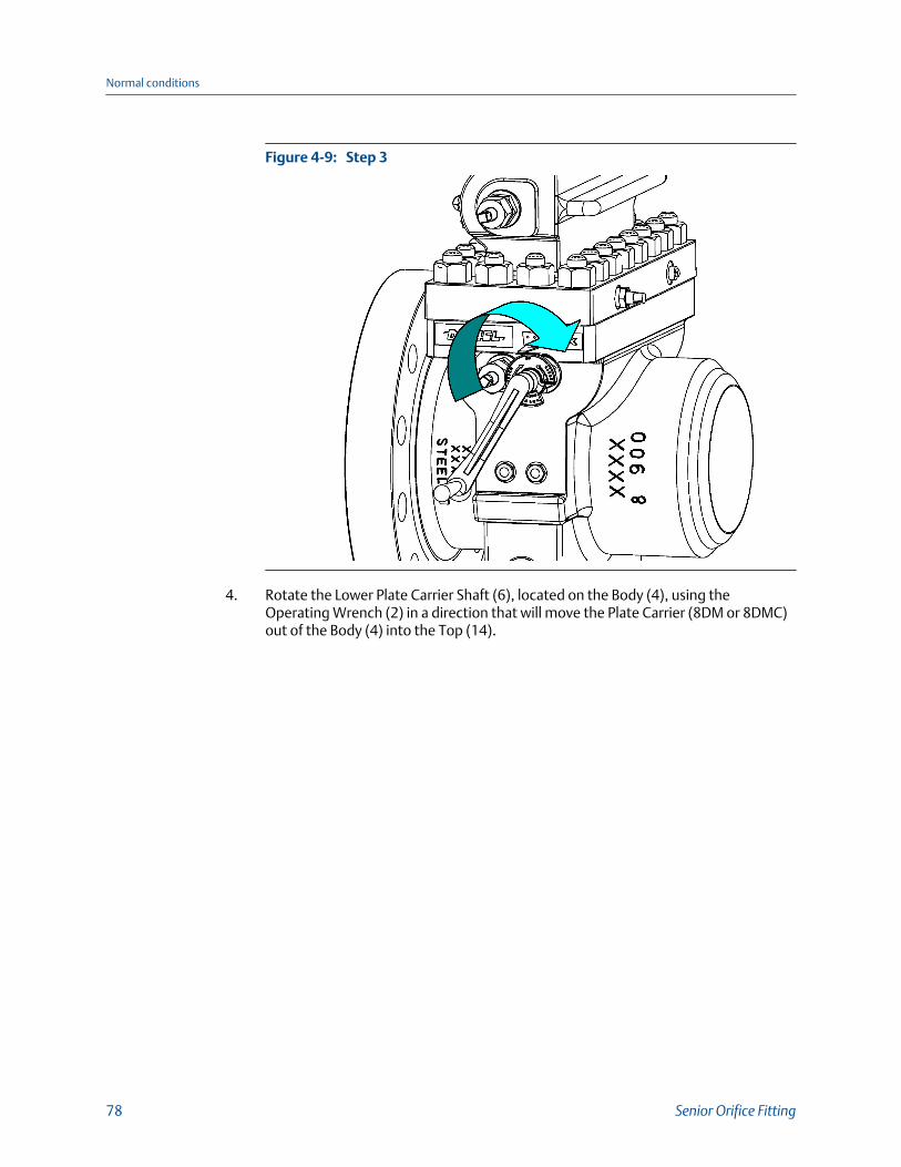
Step 3Figure 4-9:
4. Rotate the Lower Plate Carrier Shaft (6), located on the Body (4), using theOperating Wrench (2) in a direction that will move the Plate Carrier (8DM or 8DMC)out of the Body (4) into the Top (14).
Normal conditions
78 Senior Orifice Fitting

Step 4Figure 4-10:
5. Continue to rotate the Lower Plate Carrier Shaft (6) located on the Body (4) until theUpper Plate Carrier Shaft (7) located in the Top (14) begins to rotate
Normal conditions
Owner and operator manual 79

Step 5Figure 4-11:
6. Move the Operating Wrench (2) from the Lower Plate Carrier Shaft (6) located in theBody (4) on the Upper Plate Carrier Shaft (7) located in the Top (14).
Normal conditions
80 Senior Orifice Fitting

Step 6Figure 4-12:
7. Rotate the Upper Plate Carrier Shaft (7) located in the Top (14) until the Plate Carrier(8DM or 8DMC) stops against the Sealing Bar (9, 9HP).
Normal conditions
Owner and operator manual 81

Step 7Figure 4-13:
8. Close the Equalizer Valve (1) with the Operating Wrench (2).
Step 8Figure 4-14:
Normal conditions
82 Senior Orifice Fitting

9. Using the Operating Wrench (2) rotate the Slide Valve Shaft (5) until it stops and theCLOSED position specified on the Indicator Plate (5A) is in line with the IndicatorPointer (5B).
Step 9Figure 4-15:
10. Open the Bleeder Valve (10B) with the Operating Wrench (2).
Normal conditions
Owner and operator manual 83

Step 10Figure 4-16:
WARNING!PRESSURIZED FLUID HAZARDWhen opening the bleeder valve (10B) or venting the Top (14) thru the bleeder valve(10B), direct the released pressurized fluid and/or gas to safe area away from anyindividual in accordance with local environment regulations.
The bleeder valve (10B) releases pressurized fluid that may cause contamination and/oraccumulation of volatile gas mixtures. Failure to comply may cause serious injury ordeath.
NOTICEThe pressure contained in the Top (14) must be lowered to ambient pressure in order tobegin any Orifice Plate (13) procedures. When lowering the pressure in the Top (14), theoperator must direct fluid or gas escaping from the Top (14) to a safe area away from theoperator, and in accordance with local environmental regulations.
Steps 11 and 12 are ONLY required for the Seniors equipped with grease assisted,metal-to- metal slide valves. Personnel operating the Senior equipped with O-Ringseal "soft seat" design slide valves skip to step 13.
11. Remove the stem from the Grease Gun (23) with the Operating Wrench (2) andinsert a Daniel lubricant stick into the Grease Gun (23).
Normal conditions
84 Senior Orifice Fitting

Step 11Figure 4-17:
Step 11 AFigure 4-18:
Normal conditions
Owner and operator manual 85

WARNING!PRESSURIZED FLUID HAZARDUsing the Grease Gun (23), inject grease into the slide valve seat channels at a rate of 4 to6 turns per minute and only under the following conditions:
• Bleeder Valve is open.
• Sealing bar/Clamping bar is in place and tight.
Injection of the grease at a faster rate will lead to the separation of the valve strip fromthe valve seat, resulting in release of pressurized fluid which may cause death or seriousinjury.
12. Return the stem to the Grease Gun (23) and begin turning it clockwise by hand intothe Grease Gun (23) until resistance is felt. Once this is done, use the suppliedOperating Wrench (2) to continue to turn the stem clockwise, at a rate of 4 to 6turns per minute.
Step 12Figure 4-19:
ImportantBy turning the stem of the Grease Gun (23) at a rate of 4 to 6 turns per minute, the lubricant isforced through the Slide Valve Seat (18) channels at a rate that allows the lubricant to travelfreely, yet not separate the valve strip from the valve seat. This method will keep fresh greasein the lubrication passages.
If the addition of grease does not reduce the flow from the open Bleeder Valve (10B)to zero, follow these steps:
• Close the Bleeder Valve (10B),
• Open the Equalizer Valve (1), and move the Slide Valve Shaft (5) from theCLOSED to the OPEN position, and back to the CLOSED position, repeating thisaction several times.
• Return the Slide Valve Shaft (5) back to the CLOSED position.
Normal conditions
86 Senior Orifice Fitting

• Close the Equalizer Valve (1) and repeat the lubrication process.
• Open the Bleeder Valve (10B).
If leakage is still present, close the Bleeder Valve (10B) and leave the Slide ValveShaft (5) in the CLOSED position and schedule maintenance on the Senior.
13. Monitor the fluid/gas pressure in the Top (14) until it is equal to ambient conditions.
ImportantOnce the Top (14) is equal to ambient conditions, the 15 minute countdown to remove andinstall the Orifice Plate Carrier (8DM or 8DMC) begins.
Although the fluid pressure contained in the Top (14) is reduced to ambient conditions in thefollowing operations, there still remain remnants of the fluid in that chamber. The operatormust employ a system to address the remaining fluid based upon the fluid's chemicalcomposition and toxicity.
WARNING!RELEASE OF FLUIDS OR COMPONENTS HAZARDThe Clamping Bar (12 or 12HP) may not be securely in place. Sudden release of fluid orinternal components may occur. Never place the Operating Wrench (2) on the SlideValve Shaft (5), or any body part in front of the top opening in the Top (14).
Failure to comply may cause death or serious injury.
14. Loosen each Clamping Bar Screw (11) located on the Clamping Bar (12 or 12HP)approximately two turns with the Operating Wrench (2).
Normal conditions
Owner and operator manual 87
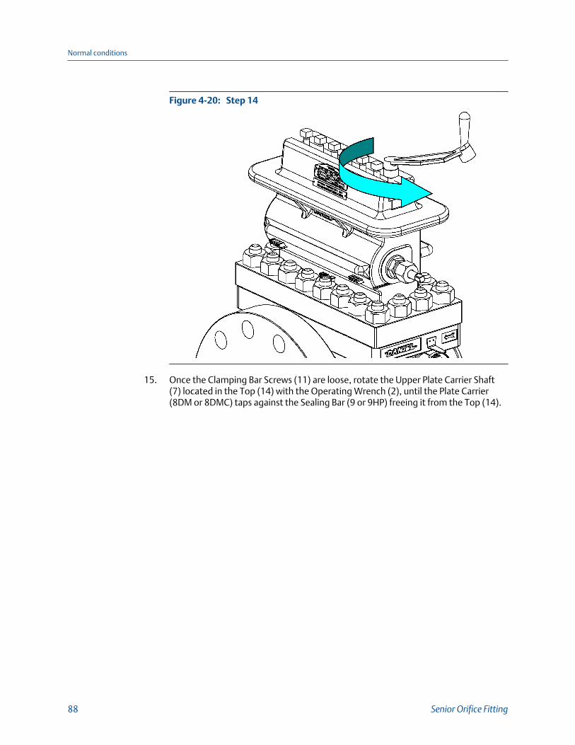
Step 14Figure 4-20:
15. Once the Clamping Bar Screws (11) are loose, rotate the Upper Plate Carrier Shaft(7) located in the Top (14) with the Operating Wrench (2), until the Plate Carrier(8DM or 8DMC) taps against the Sealing Bar (9 or 9HP) freeing it from the Top (14).
Normal conditions
88 Senior Orifice Fitting

Step 15Figure 4-21:
16. Slide the Clamping Bar (12 or 12HP) containing the Clamping Bar Screws (11), theSealing Bar (9 or 9HP) from the Top (14).
Normal conditions
Owner and operator manual 89
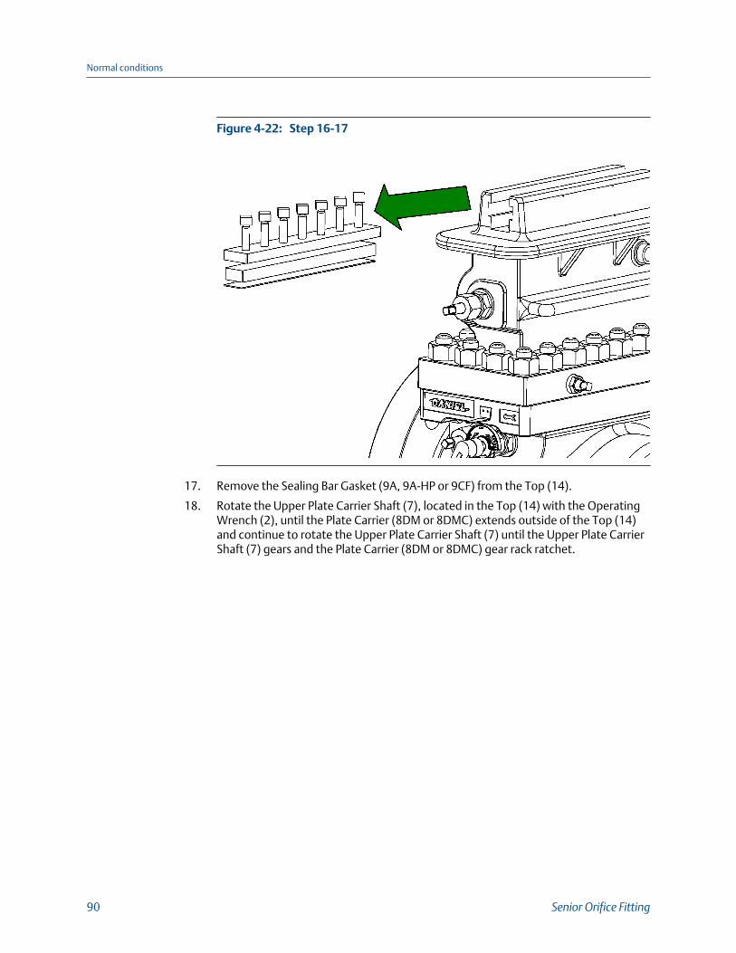
Step 16-17Figure 4-22:
17. Remove the Sealing Bar Gasket (9A, 9A-HP or 9CF) from the Top (14).
18. Rotate the Upper Plate Carrier Shaft (7), located in the Top (14) with the OperatingWrench (2), until the Plate Carrier (8DM or 8DMC) extends outside of the Top (14)and continue to rotate the Upper Plate Carrier Shaft (7) until the Upper Plate CarrierShaft (7) gears and the Plate Carrier (8DM or 8DMC) gear rack ratchet.
Normal conditions
90 Senior Orifice Fitting

Step 18Figure 4-23:
19. Remove the Orifice Plate Carrier (8DM or 8DMC) from the Top (14) and perform thescheduled work on the Orifice Plate (13) and Orifice Plate Carrier (8DM or 8DMC).
20. Insert the Orifice Plate Carrier (8DM or 8DMC) into the Top (14) until the Upper PlateCarrier Shaft (7) gears and the plate carrier gear rack mesh.
21. With the Operating Wrench (2), rotate the Upper Plate Carrier Shaft (7), located inthe Top (14), a minimum of one quarter turns OPPOSITE of the direction required tolower the Orifice Plate Carrier (8DM or 8DMC) into the Top (14). This action allowsthe Orifice Plate Carrier (8DM or 8DMC) to properly "align" the Orifice Plate Carrier(8DM or 8DMC) with the plate carrier shaft.
ImportantAlign the Orifice Plate Carrier (8DM or 8DMC) with the Upper Plate Carrier Shaft (7). Failure todo so may damage the Senior.
WARNING!PRESSURIZED FLUID HAZARDDo not lower the Plate Carrier (8DM or 8DMC) directly onto the slide valve as it maydamage the sealing features and release pressurized fluid.
Damaging the sealing features may cause contamination and/or accumulation ofvolatile gas mixtures, resulting in death or serious injury and equipment damage.
Normal conditions
Owner and operator manual 91

22. Once the Orifice Plate Carrier (8DM or 8DMC) is aligned, rotate the Upper PlateCarrier Shaft (7) with the Operating Wrench (2), in a direction to lower the OrificePlate Carrier (8DM or 8DMC) into the Top (14) until all of the Orifice Plate Carrier(8DM or 8DMC) is below the Sealing Bar Gasket (9A, 9A-HP or 9CF) surface.
Step 22Figure 4-24:
WARNING!EXPLOSION HAZARDMake sure that the Sealing Bar Gasket (9A, 9A-HP or 9CF), the Sealing Bar (9 or 9HP) andthe Clamping Bar (12 or 12HP) provide a pressure barrier between the line pressure andthe atmosphere.
Failure to properly install these parts may result in explosive separation of componentsresulting in death or serious injury.
23. Install a new Sealing Bar Gasket (9A, 9A-HP or 9CF) on to the Top (14).
Normal conditions
92 Senior Orifice Fitting
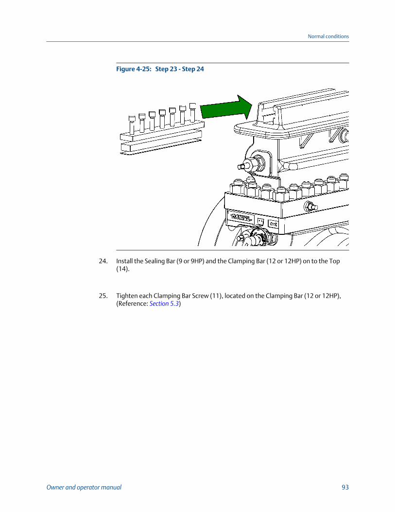
Step 23 - Step 24Figure 4-25:
24. Install the Sealing Bar (9 or 9HP) and the Clamping Bar (12 or 12HP) on to the Top(14).
25. Tighten each Clamping Bar Screw (11), located on the Clamping Bar (12 or 12HP),(Reference: Section 5.3)
Normal conditions
Owner and operator manual 93

Step 25Figure 4-26:
26. Close the Bleeder Valve (10B).
Step 26Figure 4-27:
Normal conditions
94 Senior Orifice Fitting

ImportantAfter closing the Bleeder Valve (10B), the 15 minute countdown to remove and install theOrifice Plate Carrier (8DM or 8DMC) ends.
27. Open the Equalizer Valve (1) one-half to two turns with the Operating Wrench (2).
Step 27Figure 4-28:
28. Wait several seconds for the Top (14) to reach pressure equilibrium with the linepressure contained in the Body (4).
Normal conditions
Owner and operator manual 95

Step 28Figure 4-29:
29. Using the Operating Wrench (2), rotate the Slide Valve Shaft (5) to the OPENposition.
Normal conditions
96 Senior Orifice Fitting

Step 29Figure 4-30:
30. Rotate the Upper Plate Carrier Shaft (7) with the Operating Wrench (2) in thedirection to lower the Orifice Plate Carrier (8DM or 8DMC) into the Body (4).
Normal conditions
Owner and operator manual 97

Step 30Figure 4-31:
31. Rotate the Lower Plate Carrier Shaft (6) with the Operating Wrench (2) until theOrifice Plate Carrier (8DM or 8DMC) cannot be lowered further.
Normal conditions
98 Senior Orifice Fitting

Step 31Figure 4-32:
ImportantResistance to turning will be present when the Orifice Plate Carrier (8DM or 8DMC) isapproaching its proper measurement position due to friction between the Senior Body (4)and the Orifice plate seal (8E-DSC, etc.).
32. Once the Orifice Plate Carrier (8DM or 8DMC) is positioned in the Body (4), turn theSlide Valve Shaft (5) using the Operating Wrench (2) into the CLOSED position.
Normal conditions
Owner and operator manual 99

Step 32Figure 4-33:
33. Close the Equalizer Valve (1).
Step 33Figure 4-34:
Normal conditions
100 Senior Orifice Fitting

WARNING!PRESSURIZED FLUID HAZARDWhen opening the bleeder valve (10B) or venting the Top (14) thru the bleeder valve(10B), direct the released pressurized fluid and/or gas to safe area away from anyindividual in accordance with local environment regulations.
The bleeder valve (10B) releases pressurized fluid that may cause contamination and/oraccumulation of volatile gas mixtures. Failure to comply may cause serious injury ordeath.
34. Open the Bleeder Valve (10B) to vent the Top (14).
Step 34Figure 4-35:
Steps 35 and 36 are ONLY required for Seniors equipped with grease assisted, metal-to-metal slide valves. Personnel operating the Daniel Senior Orifice Fittingsequipped with O-Ring seal "soft seat" design slide valves skip to step 37.
35. Remove the stem from the Grease Gun (23) with the Operating Wrench (2) andinsert a Daniel lubricant stick into the Grease Gun (23).
Normal conditions
Owner and operator manual 101

Step 35Figure 4-36:
Step 35AFigure 4-37:
Normal conditions
102 Senior Orifice Fitting

WARNING!PRESSURIZED FLUID HAZARDUsing the Grease Gun (23), inject grease into the slide valve seat channels at a rate of 4 to6 turns per minute and only under the following conditions:
• Bleeder Valve is open.
• Sealing bar/Clamping bar is in place and tight.
Injection of the grease at a faster rate will lead to the separation of the valve strip fromthe valve seat, resulting in release of pressurized fluid which may cause death or seriousinjury.
36. Return the stem to the Grease Gun (23) and begin turning it clockwise by hand intothe Grease Gun (23) until resistance is felt. Once this is done, use the suppliedOperating Wrench (2) to continue to turn the stem at a rate of 4 to 6 turns perminute.
Step 36Figure 4-38:
ImportantBy turning the stem of the Grease Gun (23) at a rate of 4 to 6 turns per minute, the lubricant isforced through the Slide Valve Seat (18) channels at a rate that allows the lubricant to travelfreely, yet not separate the valve strip from the valve seat. This method will keep fresh greasein the lubrication passages.
If the addition of grease does not reduce the flow from the open Bleeder Valve (10B)to zero, follow these steps:
• Close the Bleeder Valve (10B),
• Open the Equalizer Valve (1), and move the Slide Valve Shaft (5) from theCLOSED to the OPEN position, and back to the CLOSED position, repeating thisaction several times.
• Return the Slide Valve Shaft (5) back to the CLOSED position.
Normal conditions
Owner and operator manual 103
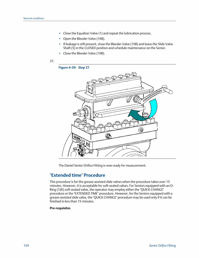
• Close the Equalizer Valve (1) and repeat the lubrication process.
• Open the Bleeder Valve (10B).
• If leakage is still present, close the Bleeder Valve (10B) and leave the Slide ValveShaft (5) in the CLOSED position and schedule maintenance on the Senior.
• Close the Bleeder Valve (10B).
37.
Step 37Figure 4-39:
The Daniel Senior Orifice Fitting is now ready for measurement.
"Extended time" ProcedureThis procedure is for the grease-assisted slide valves when the procedure takes over 15minutes. However, it is acceptable for soft-seated valves. For Seniors equipped with an O-Ring (10E) soft seated valve, the operator may employ either the "QUICK CHANGE"procedure or the "EXTENDED TIME" procedure. However, for the Seniors equipped with agrease-assisted slide valve, the "QUICK CHANGE" procedure may be used only if it can befinished in less than 15 minutes.
Pre-requisites
Normal conditions
104 Senior Orifice Fitting

WARNING!
TOXIC EXPLOSION HAZARDDo not perform any of the following steps if the Indicator Plate, the Indicator Pointer, or bothare not assembled on the Senior. Call Daniel Customer Service for assistance in obtainingreplacement components, and follow the instructions provided in Commissioning Daniel Senior Orifice Fitting installation.
Improper installation, maintenance or removal could result in explosive or toxic conditionsresulting in death or serious injury.
NOTICE
Prior to performing any maintenance or Orifice Plate (13) installation and removal operationson the Senior, personnel must visually confirm the presence of the indicator Plate (5A) on theSlide Valve Shaft (5) and the Indicator Pointer (5B) on the Body (4). Both the indicator plate andthe indicator pointer must be installed to operate this equipment safely.
Indicator plate (5A) and pointer (5B)Figure 4-40:
In preparation for the plate removal and installation process, the operator must evaluatethe meter system to determine the amount of time between the Top (14) fluid evacuationand the plate change to the full replacement of the Clamping Bar (12 or 12HP), the SealingBar (9 or 9HP), and the Sealing Bar Gasket (9A, 9A-HP or 9CF) back on the Top (14).
If the operator determines that the time between the Top (14) fluid evacuation and platechange to the full replacement of the Clamping Bar (12 or 12HP), the Sealing Bar (9 or9HP), and the Sealing Bar Gasket (9A, 9A-HP or 9CF) back on the Top (14) is less than 15minutes, then the operator may use the "QUICK CHANGE" procedure.
If the operator determines that the time between the Top (14) fluid evacuation and theplate change to the full replacement of the Clamping Bar (12 or 12HP), the Sealing Bar (9or 9HP), and the Sealing Bar Gasket (9A, 9A-HP or 9CF) back on the Top (14) is greater than15 minutes, then the operator must use the "EXTENDED TIME" procedure.
If, for any reason, the operator cannot determine the total time between the Top (14) fluidevacuation and the plate change to the full replacement of the Clamping Bar (12 or 12HP),the Sealing Bar (9 or 9HP), and the Sealing Bar Gasket (9A, 9A-HP or 9CF) back on the Top(14), then the operator must use the "EXTENDED TIME" procedure.
Normal conditions
Owner and operator manual 105
DANGER!
FLUID EXPLOSION HAZARD
Follow the instructions below to avoid inadvertent or accidental opening of the slide valve andthe propulsion of fluid or internal components from the Top (14).
Failure to comply will result in death or serious injury.
The following are the conditions required to start the removal procedure of the orificeplate:
• The Senior is operating at line pressure
• The Plate Carrier (8DM or 8DMC) is located in the measurement position within theBody (4)
• The Indicator Pointer (5B) and the Indicator Plate (5A) are installed on the Senior.
• The Slide Valve Shaft (5) is in the CLOSED position
• The Equalizer Valve (1) is in the CLOSED position
• The Bleeder Valve (10B) is in the CLOSED position
• The Sealing Bar Gasket (9A, 9A-HP or 9CF), the Sealing Bar (9 or 9HP), and theClamping Bar (12 or 12HP) are fastened to the Top (14)
• Process temperature and ambient temperature values are within range of greasecharts
• Process pressure values are within the range of grease charts.
To remove the Orifice Plate (13) from the Daniel Senior Orifice Fitting, the operatormust first balance the pressure between the Top (14) and the Body (4).
Procedure
1. Open the Equalizer Valve (1) one half to two full turns using the Operating Wrench(2).
Normal conditions
106 Senior Orifice Fitting

Step 1Figure 4-41:
2. Wait several seconds while the pressure in the Top (14) equalizes to that of the Body(4).
Normal conditions
Owner and operator manual 107

Step 2Figure 4-42:
3. Using the Operating Wrench (2) rotate the Slide Valve Shaft (5) until it stops and theOPEN position is specified on the Indicator Plate (5A) with the Indicator Pointer (5B).
Normal conditions
108 Senior Orifice Fitting
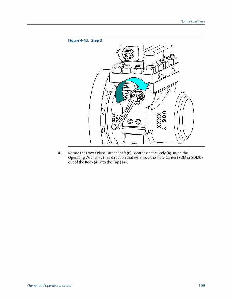
Step 3Figure 4-43:
4. Rotate the Lower Plate Carrier Shaft (6), located on the Body (4), using theOperating Wrench (2) in a direction that will move the Plate Carrier (8DM or 8DMC)out of the Body (4) into the Top (14).
Normal conditions
Owner and operator manual 109

Step 4Figure 4-44:
5. Continue to rotate the Lower Plate Carrier Shaft (6) located on the Body (4) until theUpper Plate Carrier Shaft (7) located in the Top (14) begins to rotate.
Normal conditions
110 Senior Orifice Fitting

Step 5Figure 4-45:
6. Move the Operating Wrench (2) from the Lower Plate Carrier Shaft (6) located in theBody (4) on the Upper Plate Carrier Shaft (7) located in the Top (14).
Normal conditions
Owner and operator manual 111

Step 6Figure 4-46:
7. Rotate the Upper Plate Carrier Shaft (7) located in the Top (14) until the Plate Carrier(8DM or 8DMC) stops against the Sealing Bar (9 or 9HP).
Normal conditions
112 Senior Orifice Fitting

Step 7Figure 4-47:
8. Close the Equalizer Valve (1) with the Operating Wrench (2).
Step 8Figure 4-48:
Normal conditions
Owner and operator manual 113
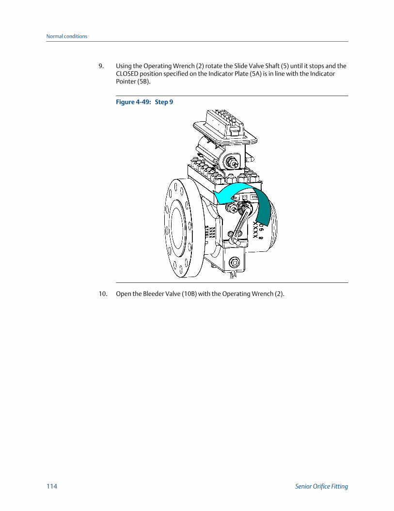
9. Using the Operating Wrench (2) rotate the Slide Valve Shaft (5) until it stops and theCLOSED position specified on the Indicator Plate (5A) is in line with the IndicatorPointer (5B).
Step 9Figure 4-49:
10. Open the Bleeder Valve (10B) with the Operating Wrench (2).
Normal conditions
114 Senior Orifice Fitting

Step 10Figure 4-50:
WARNING!PRESSURIZED FLUID HAZARDWhen opening the bleeder valve (10B) or venting the Top (14) thru the bleeder valve(10B), direct the released pressurized fluid and/or gas to safe area away from anyindividual in accordance with local environment regulations.
The bleeder valve (10B) releases pressurized fluid that may cause contamination and/oraccumulation of volatile gas mixtures. Failure to comply may cause serious injury ordeath.
The bleeder valve (10B) releases pressurized fluid that may cause contaminationand/or accumulation of volatile gas mixtures. The bleeder valve should remainclosed after orifice plate insertion in order to prevent toxic gas from being emittedinto the atmosphere. Failure to do so may cause serious injury or death.
Steps 11 and 12 are ONLY required for the Seniors equipped with grease assisted,metal-to- metal slide valves. Personnel operating the Senior equipped with O-Ringseal "soft seat" design slide valves skip to step 12.
11. Remove the stem from the Grease Gun (23) with the Operating Wrench (2) andinsert a Daniel lubricant stick into the Grease Gun (23).
Normal conditions
Owner and operator manual 115

Step 11Figure 4-51:
Step 11AFigure 4-52:
Normal conditions
116 Senior Orifice Fitting

WARNING!PRESSURIZED FLUID HAZARDUsing the Grease Gun (23), inject grease into the slide valve seat channels at a rate of 4 to6 turns per minute and only under the following conditions:
• Bleeder Valve is open.
• Sealing bar/Clamping bar is in place and tight.
Injection of the grease at a faster rate will lead to the separation of the valve strip fromthe valve seat, resulting in release of pressurized fluid which may cause death or seriousinjury.
12. Return the stem to the Grease Gun (23) and begin turning it clockwise by hand intothe Grease Gun (23) until resistance is felt. Once this is done, use the suppliedOperating Wrench (2) to continue to turn the stem clockwise, at a rate of 4 to 6turns per minute.
Step 12Figure 4-53:
ImportantBy turning the stem of the Grease Gun (23) at a rate of 4 to 6 turns per minute, the lubricant isforced through the Slide Valve Seat (18) channels at a rate that allows the lubricant to travelfreely, yet not separate the valve strip from the valve seat. This method will keep fresh greasein the lubrication passages.
Although the fluid pressure contained in the Top (14) is reduced to ambientconditions in the following operations, remnants of the fluid still remain in thatchamber. The operator must employ a system to address the remaining fluid basedupon the fluids' chemical composition and toxicity.
13. Monitor the fluid/gas pressure in the Top (14) until it is equal to ambient conditions.
Normal conditions
Owner and operator manual 117

WARNING!RELEASE OF FLUIDS OR COMPONENTS HAZARDThe Clamping Bar (12 or 12HP) may not be securely in place. Sudden release of fluid orinternal components may occur. Never place the Operating Wrench (2) on the SlideValve Shaft (5), or any body part in front of the top opening in the Top (14).
Failure to comply may cause death or serious injury.
14. Loosen each Clamping Bar Screw (11) located on the Clamping Bar (12 or 12HP)approximately two turns with the Operating Wrench (2).
Step 14Figure 4-54:
15. Once the Clamping Bar Screws (11) are loose, rotate the Upper Plate Carrier Shaft(7) located in the Top (14) with the Operating Wrench (2), until the Plate Carrier(8DM or 8DMC) taps against the Sealing Bar (9 or 9HP) freeing it from the Top (14).
Normal conditions
118 Senior Orifice Fitting

Step 15Figure 4-55:
16. Slide the Clamping Bar (12 or 12HP) containing the Clamping Bar Screws (11), theSealing Bar (9 or 9HP) from the Top (14).
Normal conditions
Owner and operator manual 119

Step 16 -17Figure 4-56:
17. Remove the Sealing Bar Gasket (9A, 9A-HP or 9CF) from the Top (14).
18. Rotate the Upper Plate Carrier Shaft (7), located in the Top (14) with the OperatingWrench (2), until the Plate Carrier (8DM or 8DMC) extends outside of the Top (14)and continue to rotate the Upper Plate Carrier Shaft (7) until the Upper Plate CarrierShaft (7) gears and the Plate Carrier (8DM or 8DMC) gear rack ratchet.
Normal conditions
120 Senior Orifice Fitting
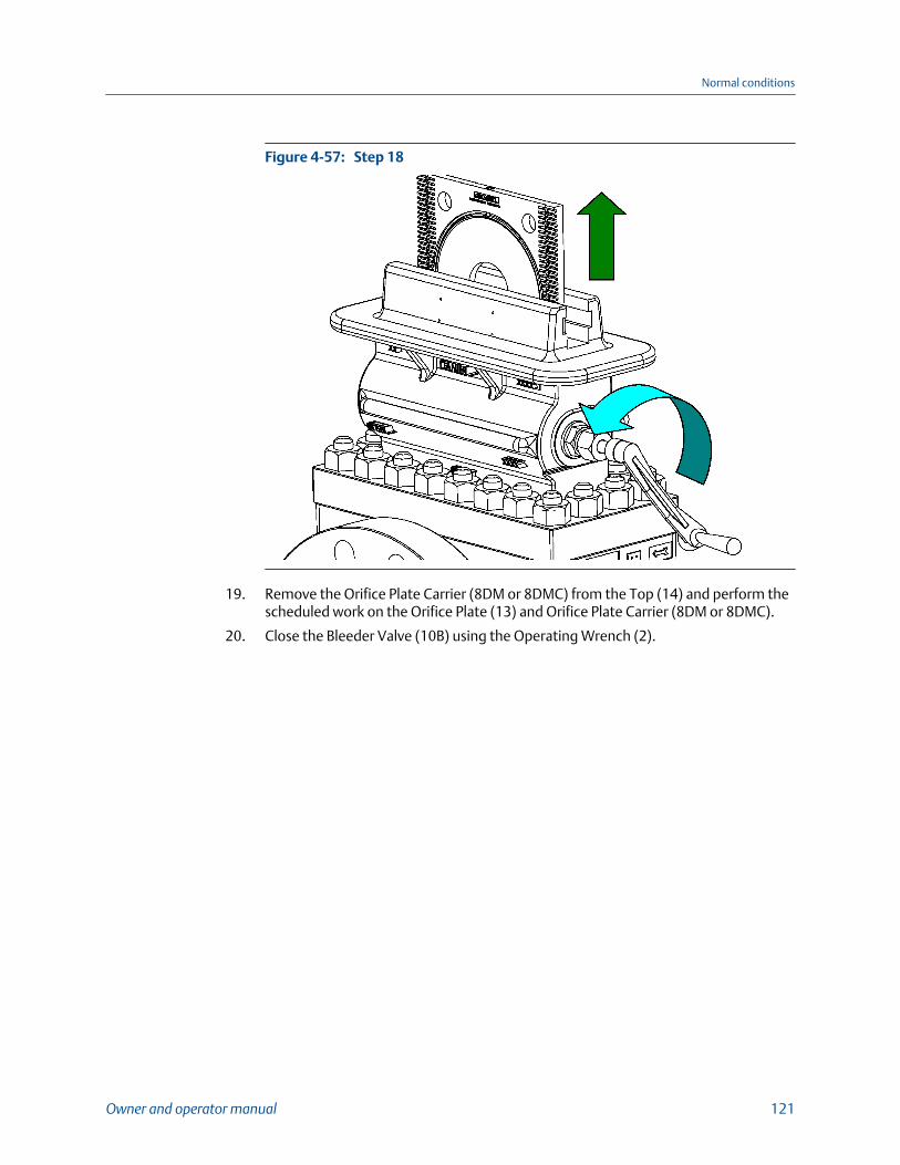
Step 18Figure 4-57:
19. Remove the Orifice Plate Carrier (8DM or 8DMC) from the Top (14) and perform thescheduled work on the Orifice Plate (13) and Orifice Plate Carrier (8DM or 8DMC).
20. Close the Bleeder Valve (10B) using the Operating Wrench (2).
Normal conditions
Owner and operator manual 121

Step 20Figure 4-58:
WARNING!EXPLOSION HAZARDMake sure that the Sealing Bar Gasket (9A, 9A-HP or 9CF), the Sealing Bar (9 or 9HP) andthe Clamping Bar (12 or 12HP) provide a pressure barrier between the line pressure andthe atmosphere.
Failure to properly install these parts may result in explosive separation of componentsresulting in death or serious injury.
Failure to properly install these parts may result in explosive separation ofcomponents resulting in serious injury or death.
21. Immediately install a new Sealing Bar Gasket (9A, 9A-HP or 9CF) on the Top (14)along with the Sealing Bar (9 or 9HP) and the Clamping Bar (12 or 12HP).
Normal conditions
122 Senior Orifice Fitting

Step 21Figure 4-59:
22. Tighten each Clamping Bar Screw (11) located on the Clamping Bar (12 or 12HP)(Reference: Section 5.3.)
Normal conditions
Owner and operator manual 123

Step 22Figure 4-60:
ImportantAt this stage in the operational procedure, the Senior is at the following conditions:
• The Equalizer Valve (1) is closed.
• The Bleeder Valve (10B) closed.
• The Slide Valve is closed.
• The Sealing Bar (9 or 9HP), the Clamping Bar (12 or 12HP), and a new Sealing Bar Gasket(9A, 9A-HP or 9CF are installed on the Top (14).
Therefore, the operator may now perform the scheduled work on the Orifice Plate (13) andthe Orifice Plate Carrier (8DM or 8DMC) without time restriction.
23. Complete work on the Orifice Plate Carrier (8DM or 8DMC) and prepare the Seniorfor insertion of the Orifice Plate Carrier (8DM or 8DMC).
24. Open the Bleeder Valve (10B) with the Operating Wrench (2)
Normal conditions
124 Senior Orifice Fitting

Step 24Figure 4-61:
Steps 25 and 26 are ONLY required for the Seniors equipped with grease assisted,metal-to- metal slide valves. Personnel operating Seniors equipped with O-Ring seal"soft seat" design slide valves skip to step 27.
25. Remove the stem from the Grease Gun (23) with the Operating Wrench (2) andinsert a Daniel lubricant stick into the Grease Gun (23).
Normal conditions
Owner and operator manual 125
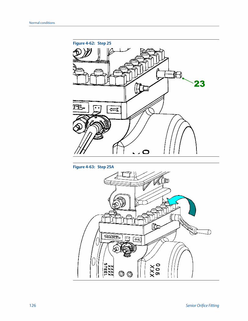
Step 25Figure 4-62:
Step 25AFigure 4-63:
Normal conditions
126 Senior Orifice Fitting

26. Return the stem to the Grease Gun (23) and begin turning it clockwise by hand intothe Grease Gun (23) until resistance is felt. Once this is done, use the suppliedOperating Wrench (2) to continue to turn the stem at a rate of 4 to 6 turns perminute.
WARNING!PRESSURIZED FLUID HAZARDUsing the Grease Gun (23), inject grease into the slide valve seat channels at a rate of 4 to6 turns per minute and only under the following conditions:
• Bleeder Valve is open.
• Sealing bar/Clamping bar is in place and tight.
Injection of the grease at a faster rate will lead to the separation of the valve strip fromthe valve seat, resulting in release of pressurized fluid which may cause death or seriousinjury.
Step 26Figure 4-64:
ImportantBy turning the stem of the Grease Gun (23) at a rate of 4 to 6 turns per minute, the lubricant isforced through the Slide Valve Seat (18) channels at a rate that allows the lubricant to travelfreely, yet not separate the valve strip from the valve seat. This method will keep fresh greasein the lubrication passages.
Normal conditions
Owner and operator manual 127

WARNING!PRESSURIZED FLUID HAZARDWhen opening the bleeder valve (10B) or venting the Top (14) thru the bleeder valve(10B), direct the released pressurized fluid and/or gas to safe area away from anyindividual in accordance with local environment regulations.
The bleeder valve (10B) releases pressurized fluid that may cause contamination and/oraccumulation of volatile gas mixtures. Failure to comply may cause serious injury ordeath.
NOTICEThe pressure contained in the Top (14) must be lowered to ambient pressure in order tobegin any Orifice Plate (13) procedures. When lowering the pressure in the Top (14), theoperator must direct fluid or gas escaping from the Top (14) to a safe area away from theoperator, and in accordance with local environmental regulations.
Although the fluid pressure contained in the Top (14) is reduced to ambientconditions in the following operations, remnants of the fluid still remain in thatchamber. The operator must employ a system to address the remaining fluid basedupon the fluids' chemical composition and toxicity.
27. Monitor the fluid/gas pressure in the Top (14) to ensure that it is equal to ambientconditions.
28. Loosen each Clamping Bar Screw (11) located on the Clamping Bar (12 or 12HP)approximately two turns with the Operating Wrench (2).
Step 28Figure 4-65:
Normal conditions
128 Senior Orifice Fitting

29. Once the Clamping Bar Screws (11) are loose, it may be necessary to use theOperating Wrench (2) to tap against the Sealing Bar (9 or 9HP) freeing it from theTop (14).
Step 29Figure 4-66:
30. Slide the Clamping Bar (12 or 12HP) containing the Clamping Bar Screws (11), theSealing Bar (9) from the Top (14).
Normal conditions
Owner and operator manual 129

Step 30 - 31Figure 4-67:
31. Remove the Sealing Bar Gasket (9A, 9A-HP or 9CF) from the Top (14).
32. Insert the Orifice Plate Carrier (8DM or 8DMC) into the Top (14) until the Upper PlateCarrier Shaft (7) gears and plate carrier gear rack mesh.
33. With the Operating Wrench (2), rotate the Upper Plate Carrier Shaft (7), located inthe Top (14), a minimum of one quarter turns OPPOSITE of the direction required tolower the Orifice Plate Carrier (8DM or 8DMC) into the Top (14). This action allowsthe Orifice Plate Carrier (8DM or 8DMC) to properly "align" the Orifice Plate Carrier(8DM or 8DMC) with the plate carrier shaft.
WARNING!PRESSURIZED FLUID HAZARDDo not lower the Plate Carrier (8DM or 8DMC) directly onto the slide valve as it maydamage the sealing features and release pressurized fluid.
Damaging the sealing features may cause contamination and/or accumulation ofvolatile gas mixtures, resulting in death or serious injury and equipment damage.
34. Once the Orifice Plate Carrier (8DM or 8DMC) is aligned, rotate the Upper PlateCarrier Shaft (7) with the Operating Wrench (2), in a direction to lower the OrificePlate Carrier (8DM or 8DMC) into the Top (14) until all of the Orifice Plate Carrier(8DM or 8DMC) is below the Sealing Bar Gasket (9A, 9A-HP or 9CF) surface.
Normal conditions
130 Senior Orifice Fitting

Step 34Figure 4-68:
WARNING!EXPLOSION HAZARDMake sure that the Sealing Bar Gasket (9A, 9A-HP or 9CF), the Sealing Bar (9 or 9HP) andthe Clamping Bar (12 or 12HP) provide a pressure barrier between the line pressure andthe atmosphere.
Failure to properly install these parts may result in explosive separation of componentsresulting in death or serious injury.
35. Install a new Sealing Bar Gasket (9A, 9A-HP or 9CF) on to the Top (14).
Normal conditions
Owner and operator manual 131
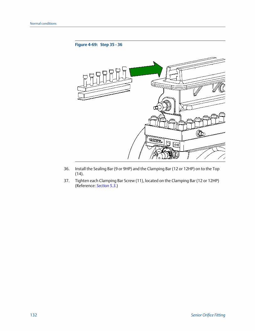
Step 35 - 36Figure 4-69:
36. Install the Sealing Bar (9 or 9HP) and the Clamping Bar (12 or 12HP) on to the Top(14).
37. Tighten each Clamping Bar Screw (11), located on the Clamping Bar (12 or 12HP)(Reference: Section 5.3.)
Normal conditions
132 Senior Orifice Fitting

Step 37Figure 4-70:
38. Close the Bleeder Valve (10B).
Step 38Figure 4-71:
Normal conditions
Owner and operator manual 133

39. Open the Equalizer Valve (1) one-half to two turns with the Operating Wrench (2).
Step 39Figure 4-72:
40. Wait several seconds for the Top (14) to reach pressure equilibrium with the linepressure contained in the Body (4).
Normal conditions
134 Senior Orifice Fitting
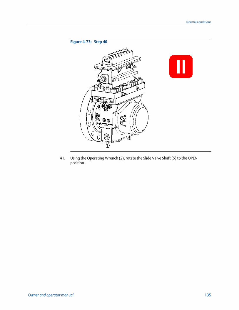
Step 40Figure 4-73:
41. Using the Operating Wrench (2), rotate the Slide Valve Shaft (5) to the OPENposition.
Normal conditions
Owner and operator manual 135

Step 41Figure 4-74:
42. Rotate the Upper Plate Carrier Shaft (7) located in the Top (14) with the OperatingWrench (2) in the direction to lower the Orifice Plate Carrier (8DM or 8DMC) into theBody (4).
Normal conditions
136 Senior Orifice Fitting

Step 42Figure 4-75:
43. Rotate the Lower Plate Carrier Shaft (6) with the Operating Wrench (2) until theOrifice Plate Carrier (8DM or 8DMC) cannot be lowered further.
Normal conditions
Owner and operator manual 137

Step 43Figure 4-76:
ImportantResistance to turning will be present when the Orifice Plate Carrier (8DM or 8DMC) isapproaching its proper measurement position due to friction between the Senior Body (4)and the Orifice plate seal (8E-DSC, etc.).
44. Once the Orifice Plate Carrier (8DM or 8DMC) is positioned in the Body (4), turn theSlide Valve Shaft (5) using the Operating Wrench (2) into the CLOSED position.
Normal conditions
138 Senior Orifice Fitting

Step 44Figure 4-77:
45. Close the Equalizer Valve (1).
Step 45Figure 4-78:
Normal conditions
Owner and operator manual 139

WARNING!PRESSURIZED FLUID HAZARDWhen opening the bleeder valve (10B) or venting the Top (14) thru the bleeder valve(10B), direct the released pressurized fluid and/or gas to safe area away from anyindividual in accordance with local environment regulations.
The bleeder valve (10B) releases pressurized fluid that may cause contamination and/oraccumulation of volatile gas mixtures. Failure to comply may cause serious injury ordeath.
46. Open the Bleeder Valve (10B) to vent the Top (14).
Step 46Figure 4-79:
Step 47 and 48 are ONLY required for Seniors equipped with grease assisted, metal-to-metal slide valves. Personnel operating the Daniel Senior Orifice Fitting equippedwith O-Ring seal "soft seat" design slide valves skip to step 49.
47. Remove the stem from the Grease Gun (23) with the Operating Wrench (2) andinsert a Daniel lubricant stick into the Grease Gun (23).
Normal conditions
140 Senior Orifice Fitting

Step 47Figure 4-80:
Step 47AFigure 4-81:
Normal conditions
Owner and operator manual 141
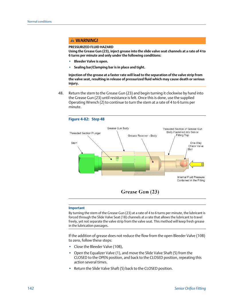
WARNING!PRESSURIZED FLUID HAZARDUsing the Grease Gun (23), inject grease into the slide valve seat channels at a rate of 4 to6 turns per minute and only under the following conditions:
• Bleeder Valve is open.
• Sealing bar/Clamping bar is in place and tight.
Injection of the grease at a faster rate will lead to the separation of the valve strip fromthe valve seat, resulting in release of pressurized fluid which may cause death or seriousinjury.
48. Return the stem to the Grease Gun (23) and begin turning it clockwise by hand intothe Grease Gun (23) until resistance is felt. Once this is done, use the suppliedOperating Wrench (2) to continue to turn the stem at a rate of 4 to 6 turns perminute.
Step 48Figure 4-82:
ImportantBy turning the stem of the Grease Gun (23) at a rate of 4 to 6 turns per minute, the lubricant isforced through the Slide Valve Seat (18) channels at a rate that allows the lubricant to travelfreely, yet not separate the valve strip from the valve seat. This method will keep fresh greasein the lubrication passages.
If the addition of grease does not reduce the flow from the open Bleeder Valve (10B)to zero, follow these steps:
• Close the Bleeder Valve (10B),
• Open the Equalizer Valve (1), and move the Slide Valve Shaft (5) from theCLOSED to the OPEN position, and back to the CLOSED position, repeating thisaction several times.
• Return the Slide Valve Shaft (5) back to the CLOSED position.
Normal conditions
142 Senior Orifice Fitting

• Close the Equalizer Valve (1) and repeat the lubrication process.
• If leakage is still present, close the Bleeder Valve (10B) and leave the Slide ValveShaft (5) in the CLOSED position and schedule maintenance on the Senior.
• Open the Bleeder Valve (10B).
49. Close the Bleeder Valve (10B).
Step 49Figure 4-83:
The Daniel Senior Orifice Fitting is now ready for measurement.
Normal conditions
Owner and operator manual 143

Normal conditions
144 Senior Orifice Fitting

5 Supplemental informationTopics covered in this chapter:
• Recommended spare parts for a one-year operation
• Lubricant information
• Torque information
5.1 Recommended spare parts for a one-yearoperation
Recommended spare partsTable 5-1:
Item number Weight Description Material Quantity
5 150-2500 Shaft CS (ZP) 1
8E-DSC/8E-DS 150-600 Orifice plate sealing unit(DSC/2"-8"; DS/10")
NBR 5
8TSC/8TS 900-2500 Orifice plate sealing unit(TSC/2"-8"; TS/10"-16")
TFE/PTFE 3
9A 150-900 Sealing bar gasket Aramid Fiber/NBR bindernon-Asbestos Flat Sheet
5
9CF 1500-2500 Sealing bar gasket Rubber O-ring 3
11 150-2500 Clamping bar screws Alloy steel (ZP) 2
18A 150-900 Slide valve seat Composition 1
18A 1500 Slide valve seat/top gasket Composition 1
14CF 1500 Body/top gasket (O-ring) Special compound 1
14CF-A 2500 Body/top gasket (Metalbacked O-ring
CS (ZP)/ NBR 1
22A 150-1500 Stuffing box/bearing pluggasket
316 SS 2
22A 2500 Stuffing box/bearing pluggasket
316 SS 2
22B 2500 Stuffing box/bearing plugo-ring
NBR O-ring 2
25A 150-1500 Packing rings TFE/PTFE 1-set
25A-HP 2500 Packing rings TFE/PTFE 1-set
25B 150-1500 Centering rings TFE/PTFE 1-set
25B-HP 2500 Centering rings TFE/PTFE 1-set
26C 2500 External gland outer o-ring NBR O-ring 1
Supplemental information
Owner and operator manual 145
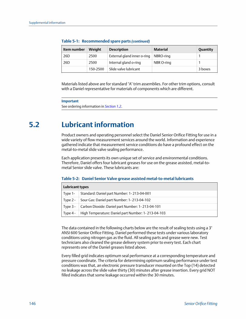
Recommended spare parts (continued)Table 5-1:
Item number Weight Description Material Quantity
26D 2500 External gland inner o-ring NBRO-ring 1
26D 2500 Internal gland o-ring NBR O-ring 1
150-2500 Slide valve lubricant 3 boxes
Materials listed above are for standard "A" trim assemblies. For other trim options, consultwith a Daniel representative for materials of components which are different.
ImportantSee ordering information in Section 1.2.
5.2 Lubricant informationProduct owners and operating personnel select the Daniel Senior Orifice Fitting for use in awide variety of flow measurement services around the world. Information and experiencegathered indicate that measurement service conditions do have a profound effect on themetal-to-metal slide valve sealing performance.
Each application presents its own unique set of service and environmental conditions.Therefore, Daniel offers four lubricant greases for use on the grease assisted, metal-to-metal Senior slide valve. These lubricants are:
Daniel Senior Valve grease assisted metal-to-metal lubricantsTable 5-2:
Lubricant types
Type 1- Standard: Daniel part Number: 1- 213-04-001
Type 2 - Sour Gas: Daniel part Number: 1- 213-04-102
Type 3 - Carbon Dioxide: Daniel part Number: 1- 213-04-101
Type 4 - High Temperature: Daniel part Number: 1- 213-04-103
The data contained in the following charts below are the result of sealing tests using a 3"ANSI 600 Senior Orifice Fitting. Daniel performed these tests under various laboratoryconditions using nitrogen gas as the fluid. All sealing parts and grease were new. Testtechnicians also cleaned the grease delivery system prior to every test. Each chartrepresents one of the Daniel greases listed above.
Every filled grid indicates optimum seal performance at a corresponding temperature andpressure coordinate. The criteria for determining optimum sealing performance under testconditions was that, an electronic pressure transducer mounted on the Top (14) detectedno leakage across the slide valve thirty (30) minutes after grease insertion. Every grid NOTfilled indicates that some leakage occurred within the 30 minutes.
Supplemental information
146 Senior Orifice Fitting

In order to perform a safe and efficient plate change operation, Daniel emphasizes that theon- site operator evaluate both the service and environmental conditions prior to selectinga lubricant. Additionally, Daniel realizes that some operators do allow leakage during aplate change operation for metal to metal valve seats based upon their experience and theservice conditions under which they are operating and have performed successful and safeplate changes.
WARNING!
LEAKAGE OF TOXIC FLUID HAZARDFor Seniors with a soft-seated valve and grease-assisted slide valves, do not use the "QUICKCHANGE" procedure if the time to complete the plate removal and installation process willexceed 15 minutes.
Exceeding this time frame can allow leakage of possible toxic fluid from the seal. Failure tofollow these instructions may result in death or serious injury.
One important factor for an owner or an operator to consider when selecting a grease for aparticular application is plate change time. This is the period in minutes required for anoperator to initiate, and complete, the Orifice Plate (13) change operation.
Refer to Section 4.2.1.
Standard grease - Type 1Figure 5-1:
Pressure (psig) v. Temperature (°F) STANDARD GREASE - TYPE 1 - Part Number:1-213-04-001 OPTIMUM SEALING RANGE WITH NITROGEN FOR A 3" ANSI 600 SENIORFITTING UNDER LABORATORY CONDITIONS. Colored coordinate boxes indicate nodetectable leakage at that Temperature and Pressure for 30 minutes.
This information can be used as a guideline when evaluating measurement applications.However, the pressure and temperature conditions to which a Senior may be exposed inan application may differ significantly from laboratory conditions.
Supplemental information
Owner and operator manual 147

ImportantCustomers should not rely solely on this information but rather must perform adequate testing onthe particular application to confirm that the grease selected is appropriate for that application andwill operate as intended.
Sour grease - Type 2Figure 5-2:
Pressure (psig) v. Temperature (°F) SOUR GAS GREASE - TYPE 2 - Part Number:1-213-04-102 OPTIMUM SEALING RANGE WITH NITROGEN FOR A 3" ANSI 600 SENIORFITTING UNDER LABORATORY CONDITIONS. Colored coordinate boxes indicate nodetectable leakage at that Temperature and Pressure for 30 minutes.
This information can be used as a guideline when evaluating measurement applications.However, the pressure and temperature conditions to which a Senior may be exposed inan application may differ significantly from laboratory conditions.
ImportantCustomers should not rely solely on this information but rather must perform adequate testing onthe particular application to confirm that the grease selected is appropriate for that application andwill operate as intended.
Supplemental information
148 Senior Orifice Fitting

Carbon Dioxide grease - Type 3Figure 5-3:
Pressure (psig) v. Temperature (°F) CARBON DIOXIDE GREASE - TYPE 3 - Part Number:1-213-04- 101 OPTIMUM SEALING RANGE WITH NITROGEN FOR A 3" ANSI 600 SENIORFITTING UNDER LABORATORY CONDITIONS. Colored coordinate boxes indicate nodetectable leakage at that Temperature and Pressure for 30 minutes.
This information can be used as a guideline when evaluating measurement applications.However, the pressure and temperature conditions to which a Senior may be exposed inan application may differ significantly from laboratory conditions.
ImportantCustomers should not rely solely on this information but rather must perform adequate testing onthe particular application to confirm that the grease selected is appropriate for that application andwill operate as intended.
Supplemental information
Owner and operator manual 149

High temperature grease - Type 4Figure 5-4:
Pressure (psig) v. Temperature (°F) HIGH TEMPERATURE GREASE - TYPE 4 - Part Number:1-213- 04-103 OPTIMUM SEALING RANGE WITH NITROGEN FOR A 3" ANSI 600 SENIORFITTING UNDER LABORATORY CONDITIONS. Colored coordinate boxes indicate nodetectable leakage at that Temperature and Pressure for 30 minutes.
This information can be used as a guideline when evaluating measurement applications.However, the pressure and temperature conditions to which a Senior may be exposed inan application may differ significantly from laboratory conditions.
ImportantCustomers should not rely solely on this information but rather must perform adequate testing onthe particular application to confirm that the grease selected is appropriate for that application andwill operate as intended.
5.3 Torque informationDaniel utilizes several joint assemblies to construct a fitting. For a fitting to pass all factorytests, assembly personnel apply a specific torque to each fastener used in the fitting toensure proper operation and to seal the unit. See Table 5-3 in this section for suggestedclamping bar screw torque values.
Product owners and product operators must realize that both time and service conditionsimpact the tightness and strength of joints originally assembled in the factory. Some, butnot all, of these service conditions are:
• Time in service or storage
• Temperature cycles
• Vibration
Supplemental information
150 Senior Orifice Fitting

• Mechanical loads
• Pressure loads
• Fastener thread condition (dirt / corrosion)
• Condition of joint assembly components (fasteners, gaskets, sealing surfaceconditions)
• Fastener lubrication and coatings
Daniel publishes these suggested torque values to help owners and users establish astarting point for applying torque to fasteners in service. The torque value applied to theclamping bar screws, necessary to achieve a seal, maybe greater or less than thesuggested torque range in Table 5-3 .
Again, these values are only a reference. They are reference values because it is impossiblefor Daniel to know all of the variable conditions (some listed above) that your fitting (underyour care) will see in actual service. Only the owner or operator, after careful considerationof a fitting's service conditions, can specify a torque value to achieve an adequate seal.Therefore, owners and operators are ultimately responsible for joint assembly torquespecifications. Again, owners and users are to use the torque values given in the followingtable as reference only.
Apply the torque values that you select using the sequencing patterns provided in thissection and in accordance with industry or company bolting procedures.
These values are FOR REFERENCE only.
Clamping bar screw (11) size and suggested torque valuesTable 5-3:
Screw size
Suggested torque range
(lbf·ft [N·m])Maximum torque
(lbf·ft [N·m])Lower Upper
1/2"-13 75 [101] 120 [163] 130 [176]
5/8"-11 120 [163] 195 [264] 265 [359]
These torques values are to help users establish a starting point to provide adequateassembly and in-service clamping force in most applications. These values are FORREFERENCE only.
DO NOT apply torque greater than the Maximum Torque value.
These torque values reflect new, heat treated, alloy steel (AISI 4140) screws.
Owners and operators are ultimately responsible for all joint assemblies within theirsystem, including the clamping bar screws of the Senior fitting.
Supplemental information
Owner and operator manual 151

Torque pattern sequencesFigure 5-5:
Supplemental information
152 Senior Orifice Fitting

Stuffing box and bearing plugFigure 5-6:
Supplemental information
Owner and operator manual 153

Supplemental information
154 Senior Orifice Fitting

Supplemental information
Owner and operator manual 155

Supplemental information
156 Senior Orifice Fitting

Supplemental information
Owner and operator manual 157

P/N 3-9008-001
Rev N
2016
Daniel Measurement and Control, Inc.11100 Brittmoore Park DriveHouston, TX 77041 USAT +1 713-467-6000F +1 713-827-4805USA Toll Free 1 888-356-9001Daniel Measurement Services, Inc.T +1 713-827-6314www.Daniel.com
Europe: Stirling, Scotland, UKT +44-1786-433400Middle East Africa: Dubai, UAET +971-4-811-8100Asia Pacific: SingaporeT +65-677-8211
©2016 Daniel Measurement and Control, Inc., All rights reserved.
The Emerson logo is a trademark and service mark of EmersonElectric Co. Daniel Measurement and Control, Inc., and DanielMeasurement Services, Inc., (Daniel) are Emerson ProcessManagement business units. The Daniel name and logo aretrademarks of Daniel Industries, Inc. The Senior, Junior, Simplex,MeterLink, SeniorSonic, JuniorSonic, and DanPac are trademarks ofDaniel Industries, Inc. All other trademarks are property of theirrespective owners.