daewoo dtq-20u9sc 21u9ss cs
TRANSCRIPT

8/12/2019 Daewoo Dtq-20u9sc 21u9ss Cs
http://slidepdf.com/reader/full/daewoo-dtq-20u9sc-21u9ss-cs 1/10

8/12/2019 Daewoo Dtq-20u9sc 21u9ss Cs
http://slidepdf.com/reader/full/daewoo-dtq-20u9sc-21u9ss-cs 2/10
8/12/2019 Daewoo Dtq-20u9sc 21u9ss Cs
http://slidepdf.com/reader/full/daewoo-dtq-20u9sc-21u9ss-cs 3/10
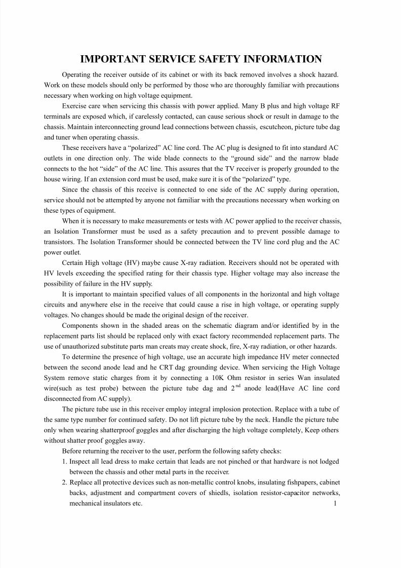
IMPORTANT SERVICE SAFETY INFORMATION
Operating the receiver outside of its cabinet or with its back removed involves a shock hazard.
Work on these models should only be performed by those who are thoroughly familiar with precautions
necessary when working on high voltage equipment.
Exercise care when servicing this chassis with power applied. Many B plus and high voltage RF
terminals are exposed which, if carelessly contacted, can cause serious shock or result in damage to the
chassis. Maintain interconnecting ground lead connections between chassis, escutcheon, picture tube dag
and tuner when operating chassis.
These receivers have a “polarized” AC line cord. The AC plug is designed to fit into standard AC
outlets in one direction only. The wide blade connects to the “ground side” and the narrow blade
connects to the hot “side” of the AC line. This assures that the TV receiver is properly grounded to the
house wiring. If an extension cord must be used, make sure it is of the “polarized” type.
Since the chassis of this receive is connected to one side of the AC supply during operation,
service should not be attempted by anyone not familiar with the precautions necessary when working on
these types of equipment.
When it is necessary to make measurements or tests with AC power applied to the receiver chassis,
an Isolation Transformer must be used as a safety precaution and to prevent possible damage to
transistors. The Isolation Transformer should be connected between the TV line cord plug and the AC
power outlet.
Certain High voltage (HV) maybe cause X-ray radiation. Receivers should not be operated with
HV levels exceeding the specified rating for their chassis type. Higher voltage may also increase the
possibility of failure in the HV supply.
It is important to maintain specified values of all components in the horizontal and high voltage
circuits and anywhere else in the receive that could cause a rise in high voltage, or operating supply
voltages. No changes should be made the original design of the receiver.
Components shown in the shaded areas on the schematic diagram and/or identified by in the
replacement parts list should be replaced only with exact factory recommended replacement parts. The
use of unauthorized substitute parts man creats may create shock, fire, X-ray radiation, or other hazards.
To determine the presence of high voltage, use an accurate high impedance HV meter connected
between the second anode lead and he CRT dag grounding device. When servicing the High Voltage
System remove static charges from it by connecting a 10K Ohm resistor in series Wan insulated
wire(such as test probe) between the picture tube dag and 2nd
anode lead(Have AC line cord
disconnected from AC supply).
The picture tube use in this receiver employ integral implosion protection. Replace with a tube of
the same type number for continued safety. Do not lift picture tube by the neck. Handle the picture tube
only when wearing shatterproof goggles and after discharging the high voltage completely, Keep others
without shatter proof goggles away.
Before returning the receiver to the user, perform the following safety checks:
1. Inspect all lead dress to make certain that leads are not pinched or that hardware is not lodged
between the chassis and other metal parts in the receiver.
2. Replace all protective devices such as non-metallic control knobs, insulating fishpapers, cabinet
backs, adjustment and compartment covers of shiedls, isolation resistor-capacitor networks,
mechanical insulators etc. 1
8/12/2019 Daewoo Dtq-20u9sc 21u9ss Cs
http://slidepdf.com/reader/full/daewoo-dtq-20u9sc-21u9ss-cs 4/10
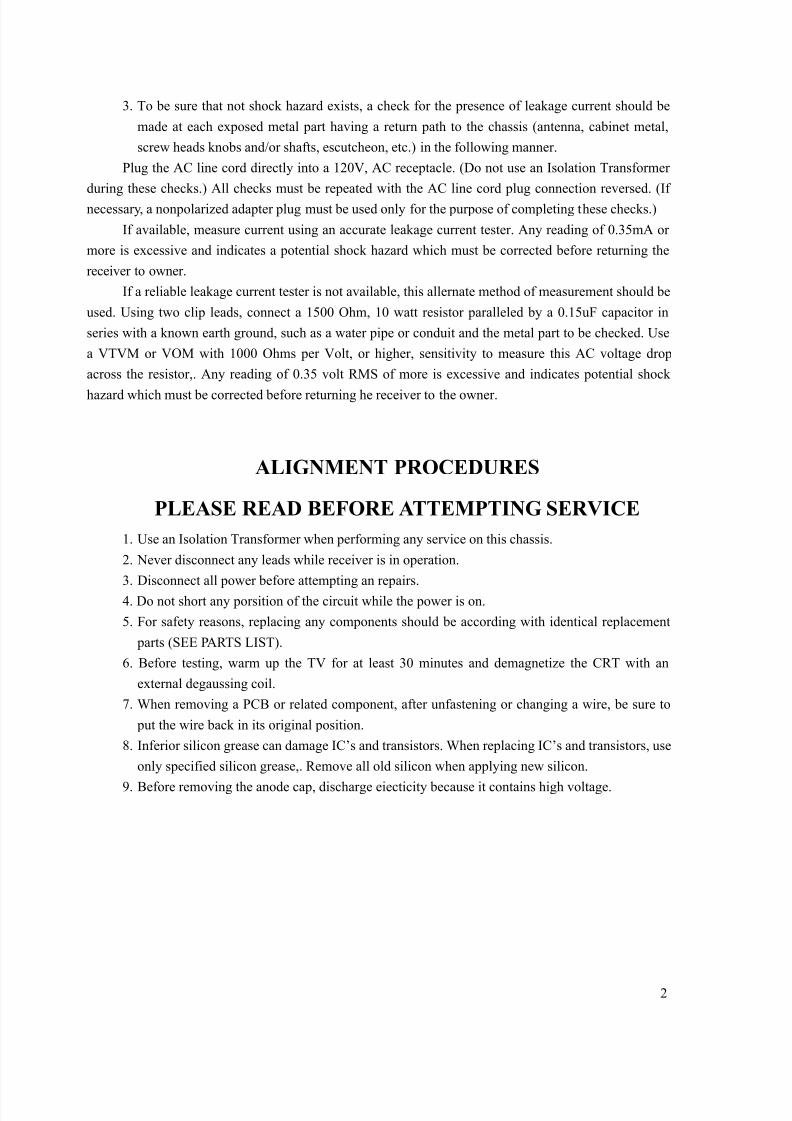
3. To be sure that not shock hazard exists, a check for the presence of leakage current should be
made at each exposed metal part having a return path to the chassis (antenna, cabinet metal,
screw heads knobs and/or shafts, escutcheon, etc.) in the following manner.
Plug the AC line cord directly into a 120V, AC receptacle. (Do not use an Isolation Transformer
during these checks.) All checks must be repeated with the AC line cord plug connection reversed. (If
necessary, a nonpolarized adapter plug must be used only for the purpose of completing these checks.)
If available, measure current using an accurate leakage current tester. Any reading of 0.35mA or
more is excessive and indicates a potential shock hazard which must be corrected before returning the
receiver to owner.
If a reliable leakage current tester is not available, this allernate method of measurement should be
used. Using two clip leads, connect a 1500 Ohm, 10 watt resistor paralleled by a 0.15uF capacitor in
series with a known earth ground, such as a water pipe or conduit and the metal part to be checked. Use
a VTVM or VOM with 1000 Ohms per Volt, or higher, sensitivity to measure this AC voltage drop
across the resistor,. Any reading of 0.35 volt RMS of more is excessive and indicates potential shock
hazard which must be corrected before returning he receiver to the owner.
ALIGNMENT PROCEDURES
PLEASE READ BEFORE ATTEMPTING SERVICE
1. Use an Isolation Transformer when performing any service on this chassis.
2. Never disconnect any leads while receiver is in operation.
3. Disconnect all power before attempting an repairs.
4. Do not short any porsition of the circuit while the power is on.
5. For safety reasons, replacing any components should be according with identical replacement
parts (SEE PARTS LIST).
6. Before testing, warm up the TV for at least 30 minutes and demagnetize the CRT with an
external degaussing coil.
7. When removing a PCB or related component, after unfastening or changing a wire, be sure to
put the wire back in its original position.
8. Inferior silicon grease can damage IC’s and transistors. When replacing IC’s and transistors, use
only specified silicon grease,. Remove all old silicon when applying new silicon.
9. Before removing the anode cap, discharge eiecticity because it contains high voltage.
2
8/12/2019 Daewoo Dtq-20u9sc 21u9ss Cs
http://slidepdf.com/reader/full/daewoo-dtq-20u9sc-21u9ss-cs 5/10
8/12/2019 Daewoo Dtq-20u9sc 21u9ss Cs
http://slidepdf.com/reader/full/daewoo-dtq-20u9sc-21u9ss-cs 6/10
8/12/2019 Daewoo Dtq-20u9sc 21u9ss Cs
http://slidepdf.com/reader/full/daewoo-dtq-20u9sc-21u9ss-cs 7/10
8/12/2019 Daewoo Dtq-20u9sc 21u9ss Cs
http://slidepdf.com/reader/full/daewoo-dtq-20u9sc-21u9ss-cs 8/10
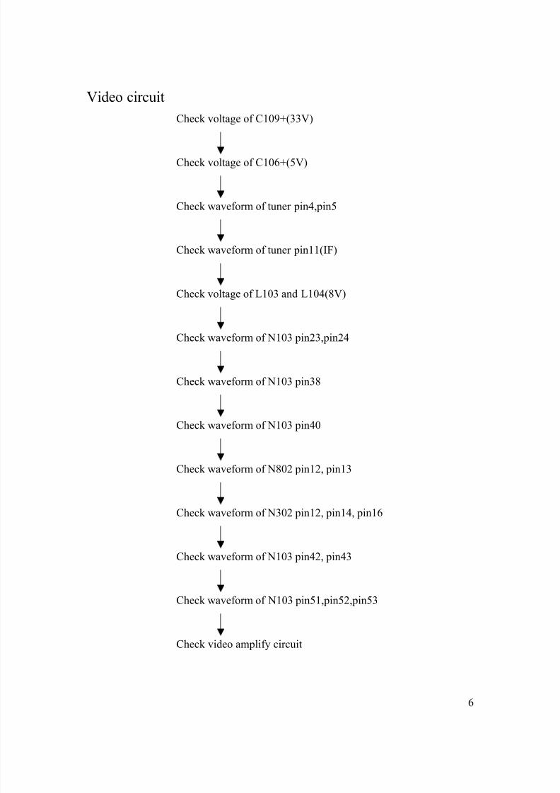
Video circuit
Check voltage of C109+(33V)
Check voltage of C106+(5V)
Check waveform of tuner pin4,pin5
Check waveform of tuner pin11(IF)
Check voltage of L103 and L104(8V)
Check waveform of N103 pin23,pin24
Check waveform of N103 pin38
Check waveform of N103 pin40
Check waveform of N802 pin12, pin13
Check waveform of N302 pin12, pin14, pin16
Check waveform of N103 pin42, pin43
Check waveform of N103 pin51,pin52,pin53
Check video amplify circuit
6
8/12/2019 Daewoo Dtq-20u9sc 21u9ss Cs
http://slidepdf.com/reader/full/daewoo-dtq-20u9sc-21u9ss-cs 9/10
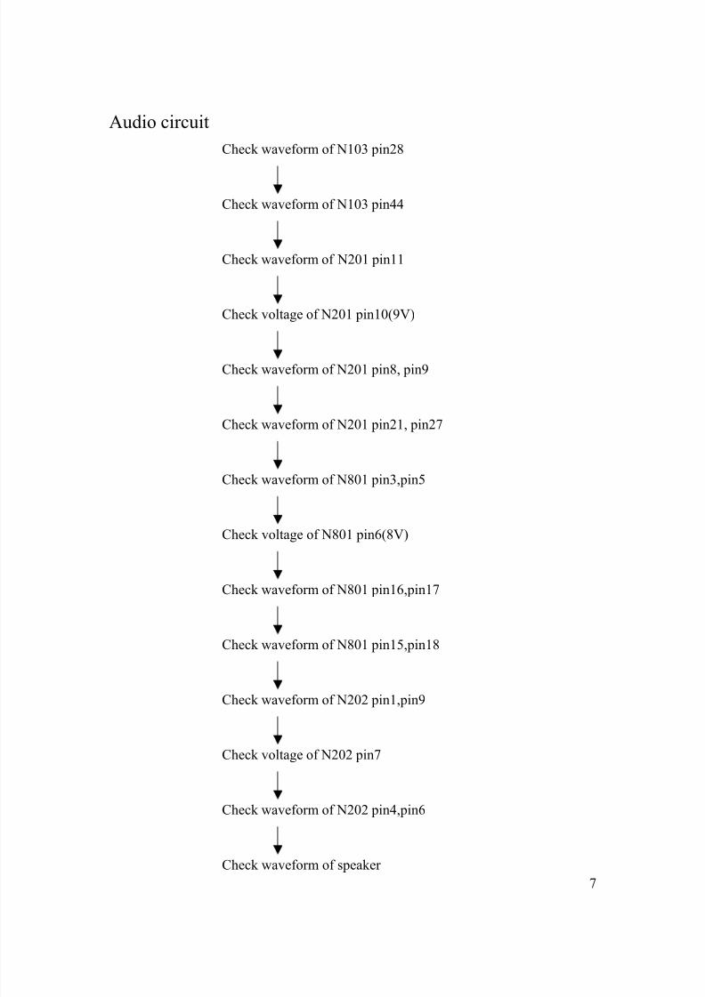
Audio circuit
Check waveform of N103 pin28
Check waveform of N103 pin44
Check waveform of N201 pin11
Check voltage of N201 pin10(9V)
Check waveform of N201 pin8, pin9
Check waveform of N201 pin21, pin27
Check waveform of N801 pin3,pin5
Check voltage of N801 pin6(8V)
Check waveform of N801 pin16,pin17
Check waveform of N801 pin15,pin18
Check waveform of N202 pin1,pin9
Check voltage of N202 pin7
Check waveform of N202 pin4,pin6
Check waveform of speaker
7
8/12/2019 Daewoo Dtq-20u9sc 21u9ss Cs
http://slidepdf.com/reader/full/daewoo-dtq-20u9sc-21u9ss-cs 10/10