d9485 davic qpsk bridge installation and operation · pdf fileol-30211-01 iii contents safety...
TRANSCRIPT

OL-30211-01
D9485 DAVIC QPSK Bridge
Installation and Operation Guide


Please Read
Important
Read this entire guide. If this guide provides installation or operation instructions, give particular attention to all safety statements included in this guide.
Notices
Trademark Acknowledgments
Cisco and the Cisco logo are trademarks or registered trademarks of Cisco and/or its affiliates in the U.S. and other countries. To view a list of Cisco trademarks, go to this URL: www.cisco.com/go/trademarks.
Third party trademarks mentioned are the property of their respective owners.
The use of the word partner does not imply a partnership relationship between Cisco and any other company. (1110R)
Publication Disclaimer
Cisco Systems, Inc. assumes no responsibility for errors or omissions that may appear in this publication. We reserve the right to change this publication at any time without notice. This document is not to be construed as conferring by implication, estoppel, or otherwise any license or right under any copyright or patent, whether or not the use of any information in this document employs an invention claimed in any existing or later issued patent.
Copyright
© 2014 Cisco and/or its affiliates. All rights reserved.
Information in this publication is subject to change without notice. No part of this publication may be reproduced or transmitted in any form, by photocopy, microfilm, xerography, or any other means, or incorporated into any information retrieval system, electronic or mechanical, for any purpose, without the express permission of Cisco Systems, Inc.

OL-30211-01 iii
Contents
Safety Precautions v
FCC Compliance ix
About This Guide xi
Chapter 1 Introducing the DAVIC QPSK Bridge 1
System Overview ..................................................................................................................... 2 The QPSK Bridge Communication ........................................................................................ 6 Front Panel Overview ............................................................................................................. 7 Back Panel Overview ............................................................................................................... 9
Chapter 2 Installing the DAVIC QPSK Bridge 11
Installation Prerequisites ...................................................................................................... 12 Measure RF Output on Existing QPSK ............................................................................... 14 Unpack and Inspect the QPSK Bridge ................................................................................ 15 Install the DAVIC QPSK Bridge into a Rack ...................................................................... 16 Connect Power Sources ......................................................................................................... 17 Connect the Test Port (Optional) ......................................................................................... 19 Connect the Craft Port (Optional) ....................................................................................... 20 Connect the Ethernet Port ..................................................................................................... 21 Connect the RF Input Ports .................................................................................................. 22 Connect the RF Output Ports ............................................................................................... 23 Provision the QPSK Bridge on the DNCS .......................................................................... 24 Power On the QPSK Bridge .................................................................................................. 25 Install the QPSK Bridge Software ........................................................................................ 27
Chapter 3 Operating the DAVIC QPSK Bridge 31
QPSK Bridge User Interfaces ................................................................................................ 32 QPSK Bridge Shell Menu ...................................................................................................... 34 QPSK Bridge Web Interface.................................................................................................. 60 LCD Interface.......................................................................................................................... 67 Upgrading the QPSK Bridge ................................................................................................ 75
Chapter 4 Using the Delay Mode in the QPSK Data Link 79
Feature Implementation ........................................................................................................ 80 Delay Mode Setup and Operation ....................................................................................... 81

Contents
iv OL-30211-01
Design Examples .................................................................................................................... 83
Chapter 5 Troubleshooting the DAVIC QPSK Bridge 85
Routine Maintenance ............................................................................................................. 86 General Troubleshooting Guidelines .................................................................................. 88 Troubleshoot Alarms ............................................................................................................. 89
Chapter 6 Customer Information 103
Appendix A QPSK Bridge Configuration File 105
The QPSK Configuration File ............................................................................................. 106

Safety Precautions
OL-30211-01 v
Safety Precautions
Read, Retain, and Follow These Instructions Carefully read all safety and operating instructions before operating this product. Follow all operating instructions that accompany this product. Retain the instructions for future use. Give particular attention to all safety precautions.
Warning and Caution Icons
WARNING:
Avoid personal injury and product damage! Do not proceed beyond any icon until you fully understand the indicated conditions.
The following icons alert you to important information about the safe operation of this product:
You will find this icon in the literature that accompanies this product. This icon indicates important operating or maintenance instructions.
You may find this icon affixed to this product and in this document to alert you of electrical safety hazards. On this product, this icon indicates a live terminal; the arrowhead points to the terminal device.
You may find this icon affixed to this product. This icon indicates a protective earth terminal.
You may find this icon affixed to this product. This icon indicates excessive or dangerous heat.
You may find this symbol affixed to this product and in this document. This symbol indicates an infrared laser that transmits intensity-modulated light and emits invisible laser radiation and an LED that transmits intensity-modulated light.
Heed All Warnings Adhere to all warnings on the product and in the operating instructions.
Avoid Electric Shock Follow the instructions in this warning.
WARNING:
To reduce risk of electric shock, perform only the instructions that are included in the operating instructions. Refer all servicing to qualified service personnel.

Safety Precautions
vi OL-30211-01
Servicing
WARNING:
Avoid electric shock! Opening or removing the cover may expose you to dangerous voltages.
Do not open the cover of this product and attempt service unless instructed to do so in the operating instructions. Refer all servicing to qualified personnel only.
Cleaning, Water, Moisture, Open Flame To protect this product against damage from moisture and open flames, do the following:
Before cleaning, unplug this product from the AC outlet. Do not use liquid or aerosol cleaners. Use a dry cloth for cleaning.
Do not expose this product to moisture.
Do not place this product on a wet surface or spill liquids on or near this product.
Do not place or use candles or other open flames near or on this product.
Ventilation To protect this product against damage from overheating, do the following:
This product has openings for ventilation to protect it from overheating. To ensure product reliability, do not block or cover these openings.
Do not open this product unless otherwise instructed to do so.
Do not push objects through openings in the product or enclosure.
Placement To protect this product against damage from breakage, do the following:
Place this product close enough to a mains AC outlet to accommodate the length of the product power cord.
Route all power supply cords so that people cannot walk on, or place objects on, or lean objects against them. This can pinch or damage the cords. Pay particular attention to cords at plugs, outlets, and the points where the cords exit the product.
Make sure the mounting surface or rack is stable and can support the size and weight of this product.
WARNING:
Avoid personal injury and damage to this product! An unstable surface may cause this product to fall.

Safety Precautions
OL-30211-01 vii
When moving a cart that contains this product, check for any of the following possible hazards:
Move the cart slowly and carefully. If the cart does not move easily, this condition may indicate obstructions or cables that you may need to disconnect before moving this cart to another location.
Avoid quick stops and starts when moving the cart.
Check for uneven floor surfaces such as cracks or cables and cords.
WARNING:
Avoid personal injury and damage to this product! Move any appliance and cart combination with care. Quick stops, excessive force, and uneven surfaces may cause the appliance and cart to overturn.
Fuse When replacing a fuse, heed the following warnings.
WARNING:
Avoid electric shock! Always disconnect all power cables before you change a fuse.
WARNING:
Avoid product damage! Always use a fuse that has the correct type and rating. The correct type and rating are indicated on this product.
Grounding This Product (U.S.A. and Canada Only)
Safety Plugs
If this product is equipped with either a three-prong (grounding pin) safety plug or a two-prong (polarized) safety plug, do not defeat the safety purpose of the polarized or grounding-type plug. Follow these safety guidelines to properly ground this product:
For a 3-prong plug (consists of two blades and a third grounding prong), insert the plug into a grounded mains, 3-prong outlet.
Note: This plug fits only one way. The grounding prong is provided for your safety. If you are unable to insert this plug fully into the outlet, contact your electrician to replace your obsolete outlet.
For a 2-prong plug (consists of one wide blade and one narrow blade), insert the plug into a polarized mains, 2-prong outlet in which one socket is wider than the other.
Note: If you are unable to insert this plug fully into the outlet, try reversing the plug. The wide blade is provided for your safety. If the plug still fails to fit, contact an electrician to replace your obsolete outlet.

Safety Precautions
viii OL-30211-01
Grounding Terminal
If this product is equipped with an external grounding terminal, attach one end of an 18-gauge wire (or larger) to the grounding terminal; then, attach the other end of the wire to an earth ground, such as an equipment rack that is grounded.
20050727 Headend/Rack

FCC Compliance
OL-30211-01 ix
FCC Compliance Where this equipment is subject to U.S.A. FCC and/or Industry Canada rules, the following statements apply.
United States FCC Compliance This device has been tested and found to comply with the limits for a Class A digital device, pursuant to part 15 of the FCC Rules. These limits are designed to provide reasonable protection against such interference when this equipment is operated in a commercial environment.
This equipment generates, uses, and can radiate radio frequency energy, and if not installed and used in accordance with the instruction manual may cause harmful interference to radio communications. Operation of this equipment in a residential area is likely to cause harmful interference, in which case users will be required to correct the interference at their own expense.
Canada EMI Regulation This Class A digital apparatus complies with Canadian ICES-003.
Cet appareil numérique de la class A est conforme à la norme NMB-003 du Canada. 20061110 FCC HE


About This Guide
OL-30211-01 xi
About This Guide
Introduction
This guide describes the Cisco Model D9485 (DAVIC) Quadrature Phase-Shift Keying (QPSK) Bridge. The unit may be purchased with redundant AC power supplies or redundant DC power supplies. This guide provides installation, operation, and troubleshooting procedures (including routine maintenance), as well as technical specifications.
Note: In this guide the DAVIC QPSK Modulator/Demodulator Bridge will be referred to as the QPSK Bridge.
Purpose
This guide provides a detailed specifications and component description for the QPSK Bridge. After reading this guide, you will be able to successfully install, operate, and troubleshoot the QPSK Bridge. In addition, you will be able to perform routine maintenance which will aid in trouble-free operation. This guide also includes a detailed specifications appendix and component descriptions.
Audience
This guide is written for Digital Broadband Delivery System (DBDS) system administrators, Digital Network Control System (DNCS) operators, call center personnel, and system operators who are responsible for installing and operating the QPSK Bridge. These individuals should have extensive working experience with cable communications equipment.
Document Version
This is the first formal release of this document.


OL-30211-01 1
Introduction
This chapter describes how the QPSK Bridge functions, and how it functions within the DBDS. This chapter also includes illustrations and descriptions of the QPSK Bridge front and back panel components.
1 Chapter 1 Introducing the DAVIC QPSK Bridge
In This Chapter
System Overview .................................................................................... 2
The QPSK Bridge Communication ....................................................... 6
Front Panel Overview ............................................................................ 7
Back Panel Overview.............................................................................. 9

Chapter 1 Introducing the DAVIC QPSK Bridge
2 OL-30211-01
System Overview
Introduction
The D9485 QPSK Bridge replaces the functions of the D9482 Modulator and up to eight D9494/D9492 demodulators. It is an integral component of the DBDS. The QPSK Bridge works with Digital Home Communication Terminals (DHCTs) to provide a forward-signaling and reverse-communications path for interactive two-way video and data services.
The Modulating/Demodulating Process
The QPSK Bridge’s internal QPSK modulator initiates and controls configuration and setup through the QPSK forward path. The QPSK modulator splits messages into Asynchronous Transfer Mode (ATM) cells, formats the messages in DAVIC-compliant frames, adds QPSK modulation, and then transmits the messages to the DHCT at a rate of 1.544 Mbps. After the DHCTs are configured, all control and status information travels through the QPSK forward path, while all video and audio sources are carried by high-bandwidth Quadrature Amplitude Modulation (QAM) channels to the DHCT via a separate QAM modulator.
The QPSK Bridge’s internal QPSK demodulators receive the messages that originate from a DHCT, such as a request for a service, on a 1.544 Mbps reverse-path channel. The QPSK demodulators demodulate the incoming QPSK signals, perform error correction on the detected data, and transmit the messages to the main internal processor in the QPSK Bridge. The QPSK Bridge uses the slot number information inserted by the internal QPSK demodulator, along with the demodulator port number (for example, reverse channel number) to create a “success feedback” word to acknowledge or confirm receipt to the DHCT. These words generate the “acknowledge bits.” The DHCT needs these bits to determine whether its cell was received successfully. Received cells from the demodulators are routed to the main memory of the QPSK Bridge, where complete messages are reassembled. The QPSK Bridge processes these reassembled messages as a part of its Media Access Control (MAC) functions. The QPSK Bridge serves as a DAVIC Router by implementing the DAVIC MAC functions and by communicating signaling and status information back to the DNCS through an Ethernet/IP connection.

System Overview
OL-30211-01 3
Diagram of Major DBDS Components
The following diagram shows the major components of the DBDS:

Chapter 1 Introducing the DAVIC QPSK Bridge
4 OL-30211-01
Major Stages and Descriptions
Note: The following table describes the operational stages of the QPSK Bridge:
Stage Description
RF Inputs The QPSK demodulator(s) receive a QPSK reverse burst carrier signal from the DHCT by way of the hybrid fiber coax (HFC) CATV plant through its Radio Frequency (RF) input ports in the range of 5 to 42 MHz.
Tuner/Demodulator Each tuner/demodulator can be configured to a specific input frequency in the 5.00-42.00 MHz range in 250 KHz steps. There are four input level ranges supported by the demodulator, as follows:
Range 1 -13 to +3 dBmV
Range 2 -5 to +11 dBmV
Range 3 +3 to +19 dBmV
Range 4 +11 to +27 dBmV
Modulator The low frequency modulator port is used for typical installation where the downstream DAVIC channel is configured in the 70-130 MHz range.
The high frequency modulator port can be used to support CATV plants where the downstream split is greater than 130Mhz.
Note: The HF port is reserved for future use.
The low frequency and high frequency ports contain the same data. If both ports are active, the downstream DAVIC signal is cloned and output by both ports.
Main Processor Controls all user interfaces (LCD, buttons, LEDs, Craft Port, Web interface, and so on).
Controls the modulators/demodulators.
Monitors the environmental conditions of the QPSK Bridge and adjusts fan speeds to ensure adequate cooling.
Monitors power supplies.
Performs DAVIC MAC functions.
Interfaces with the DNCS via remote procedure calls (RPC).

System Overview
OL-30211-01 5
Internal Components
The following illustration identifies the internal components and processes of the QPSK Bridge:

Chapter 1 Introducing the DAVIC QPSK Bridge
6 OL-30211-01
The QPSK Bridge Communication This section describes how the QPSK Bridge communicates with devices on the Ethernet network and devices on the DAVIC network.
Communication Path
The QPSK Bridge is a DAVIC-compliant headend QPSK signaling hub. This single device acts as a bridge between the Ethernet Network and the DAVIC network. The QPSK Bridge uses BOOTP to get its IP settings for the Ethernet interface. On the DAVIC network, the QPSK Bridge performs all of the MAC functionality required to allow a DAVIC device to send/receive data to/from the Ethernet network.
Replacement of Existing DAVIC Modulator / Demodulators
A single D9485 QPSK Bridge replaces the functionality of one D9482 Modulator and up to eight D9494 / D9492 demodulators.

Front Panel Overview
OL-30211-01 7
Front Panel Overview
Front Panel Components
The following illustration shows the front panel components of the QPSK Bridge:
Description of Components
The following table contains the front panel alarm and component descriptions that correspond to each number in the preceding labeled diagram of the QPSK Bridge front panel:
Item Component Description
1 Front Panel Retaining Thumb Screws
Two thumb screws that secure the protective front panel encasing the replaceable fan modules.
2 Fan Modules Three field-replaceable fan modules for cooling internal circuitry.
3 RF Output Monitor Port Single BNC connector, which provides a monitor for the low frequency RF output port located on the rear of the chassis.
4 LED Indicators:
ALARM indicator (red/yellow) illuminates for any alarm. Refer to Troubleshooting the DAVIC QPSK Bridge (on page 85) for more information.
CW Mode (yellow) illuminates when the output modulator(s) are in Continuous Wave mode.
BURST DATA indicator (green) illuminates when the demodulator(s) are receiving data.
5 LCD Alphanumeric Display
Displays information and menus for front panel keys.

Chapter 1 Introducing the DAVIC QPSK Bridge
8 OL-30211-01
Item Component Description
6 Directional buttons and Enter button.
Allows you to navigate through the LCD menus, make selections, and save changes to non-volatile memory.
Back Panel Overview
OL-30211-01 9
Back Panel Overview
Back Panel Components
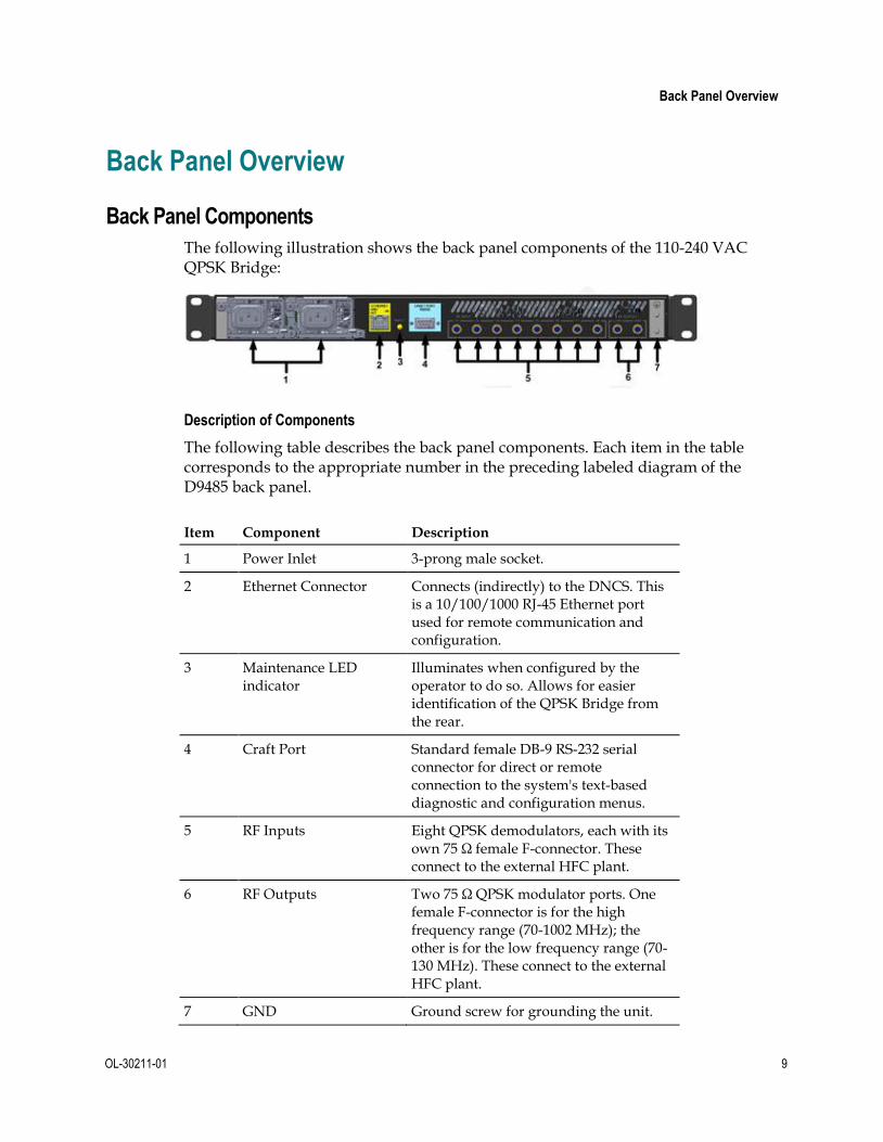
The following illustration shows the back panel components of the 110-240 VAC QPSK Bridge:
Description of Components
The following table describes the back panel components. Each item in the table corresponds to the appropriate number in the preceding labeled diagram of the D9485 back panel.
Item Component Description
1 Power Inlet 3-prong male socket.
2 Ethernet Connector Connects (indirectly) to the DNCS. This is a 10/100/1000 RJ-45 Ethernet port used for remote communication and configuration.
3 Maintenance LED indicator
Illuminates when configured by the operator to do so. Allows for easier identification of the QPSK Bridge from the rear.
4 Craft Port Standard female DB-9 RS-232 serial connector for direct or remote connection to the system's text-based diagnostic and configuration menus.
5 RF Inputs Eight QPSK demodulators, each with its own 75 Ω female F-connector. These connect to the external HFC plant.
6 RF Outputs Two 75 Ω QPSK modulator ports. One female F-connector is for the high frequency range (70-1002 MHz); the other is for the low frequency range (70-130 MHz). These connect to the external HFC plant.
7 GND Ground screw for grounding the unit.

Chapter 1 Introducing the DAVIC QPSK Bridge
10 OL-30211-01
Back Panel Components for 48 VDC QPSK Bridge
The following illustration shows the back panel components of the 48 VDC QPSK Bridge:
Description of Components
The following table describes the back panel components:
Item Component Description
1 Power Inlet Three position, screw-cage, clamp plug (Phoenix Contact 1804917 supplied with unit), with a mating jack on the unit. Recommended wire AWG is 12 maximum, 18 minimum.
2 Ethernet Connector Connects (indirectly) to the DNCS. This is a 10/100/1000 RJ-45 Ethernet port used for remote communication and configuration.
3 Maintenance LED indicator
Illuminates when configured by the operator to do so. Allows for easier identification of the QPSK Bridge from the rear.
4 Craft Port Standard female DB-9 RS-232 serial connector for direct or remote connection to the system's text-based, diagnostic and configuration menus.
5 RF Inputs Eight QPSK demodulators, each with its own 75 Ω female F-connector. These connect to the external HFC plant.
6 RF Outputs Two 75 Ω QPSK modulator ports. One female F-connector is for the High frequency range (70-1002 MHz); the other is for the Low frequency range (70-130 MHz). These connect to the external HFC plant.
7 GND Ground screw for grounding the unit.

OL-30211-01 11
Introduction
This chapter provides procedures for installing the QPSK Bridge into a rack and for connecting the QPSK Bridge to other DBDS components. For detailed instructions on how to provision the QPSK Bridge on the DNCS, refer to the DNCS online help.
Important: The QPSK Bridge must be installed in the system headend before you can perform any calibration or provisioning.
2 Chapter 2 Installing the DAVIC QPSK Bridge
In This Chapter
Installation Prerequisites ..................................................................... 12
Measure RF Output on Existing QPSK .............................................. 14
Unpack and Inspect the QPSK Bridge ............................................... 15
Install the DAVIC QPSK Bridge into a Rack ..................................... 16
Connect Power Sources ........................................................................ 17
Connect the Test Port (Optional) ........................................................ 19
Connect the Craft Port (Optional) ...................................................... 20
Connect the Ethernet Port .................................................................... 21
Connect the RF Input Ports ................................................................. 22
Connect the RF Output Ports .............................................................. 23
Provision the QPSK Bridge on the DNCS ......................................... 24
Power On the QPSK Bridge ................................................................. 25
Install the QPSK Bridge Software ....................................................... 27

Chapter 2 Installing the DAVIC QPSK Bridge
12 OL-30211-01
Installation Prerequisites This section describes the rack, power, and operating temperature requirements for the QPSK Bridge.
Rack Requirements
The QPSK Bridge fits into a standard rack mount: type EIA RS-310.
CAUTION:
When installing the QPSK Bridge into a rack, be careful not to tangle or strain interconnecting cables.
Power Requirements
The QPSK Bridge requires a power source with the following specifications:
Item Specification
Voltage 48 VDC +20/-15%
100-240 VAC model: 90 to 264 VAC (100 to 240 VAC power systems)
WARNING:
Avoid damaging the QPSK Bridge and creating a possible fire hazard! Do not connect the QPSK Bridge to an incorrect power source.
Power < 175W
Connector Specifications
48 VDC model: Three-position screw-cage clamp plug (Phoenix Contact 1804917 supplied with unit), with mating jack on unit. Recommended wire AWG is 12 maximum, 18 minimum.
100-240 VAC model: Three-prong male socket
Line frequency (AC) 47 to 63 Hz (50 to 60 Hz power systems)

Installation Prerequisites
OL-30211-01 13
WARNINGS:
This product is for indoor use only.
This product must be installed in accordance with all national and local building/electrical codes.
The main disconnect for the AC powered unit is the line cord. The AC plug needs to be readily accessible or an alternate disconnect installed near the unit.
The DC supply branch circuit should be fused for 20A or less. A power disconnect is required.
Operating Temperature
The operating temperature of this equipment is 0 to 50°C (32 to 122°F).
CAUTION:
Avoid damage to this product! Your warranty is void if you operate this product above or below the maximums specified operating temperature.
Avoid damage to this product! Your warranty is void if you install this product without proper ventilation.
To help maintain the operating temperature in the acceptable range, follow these guidelines:
Place the equipment in an air-conditioned environment
Keep cooling vents obstruction-free
Note: The intake vents are on the front panel. The exhaust vent is on the back panel.
Maintain a cool temperature in your headends and hubs where the QPSK Bridges are in use.

Chapter 2 Installing the DAVIC QPSK Bridge
14 OL-30211-01
Measure RF Output on Existing QPSK Prior to installing the new D9485 QPSK Bridge, measure the RF output power levels on the QPSK modulator you are replacing. Then, after installing the new D9485 QPSK Bridge, use the front panel of the D9485 QPSK Bridge to match those output levels.

Unpack and Inspect the QPSK Bridge
OL-30211-01 15
Unpack and Inspect the QPSK Bridge This section provides the procedures for unpacking and inspecting the QPSK Bridge.
Carrier’s Responsibility
We inspect and carefully pack all products before shipment. The carrier is responsible for safe shipping and delivery. Do not return products damaged in transit to us. If there are any missing parts or damage to the product, contact Cisco Services.
Note: Retain all boxes for future equipment shipping needs. They have been designed for use with this equipment.
Unpacking and Inspecting Procedure
Follow these steps to unpack and inspect the QPSK Bridge:
1 Review the safety precautions.
2 Inspect the shipping carton for visible damage.
3 Open the shipping carton.
4 Remove all packing material.
5 Inspect the product for visible damage.
6 Inspect the box or product for loose items that may indicate concealed damage.
7 Inspect for missing parts, using the packing slip as a guide.

Chapter 2 Installing the DAVIC QPSK Bridge
16 OL-30211-01
Install the DAVIC QPSK Bridge into a Rack This section describes the rack requirements and the procedure for installing the QPSK Bridge into a rack.
Rack Requirements
The QPSK Bridge dimensions are 1.75 inches high x 19.00 inches wide x 16.5 inches in diameter. The QPSK Bridge fits into a type EIA RS-310 rack mount.
CAUTION:
Do not to tangle or strain interconnecting cables.
Be sure to install additional support.
Installing the QPSK Bridge into a Rack
Follow these steps to install the QPSK Bridge into a rack:
1 Place the QPSK demodulator in the rack.
2 Insert a mounting screw through each of the four mounting holes on the attached angle support brackets of the QPSK Bridge and then into the rack.
3 Firmly tighten each mounting screw.
Important: When you use the attached angle support brackets, you can install the QPSK Bridges above or below each other in the rack. These support brackets provide additional support and allow correct air circulation through the unit and compensate for the additional weight of wire connectors and cabling.

Connect Power Sources
OL-30211-01 17
Connect Power Sources This section contains instructions for connecting the DC and AC power sources to the QPSK Bridge.
Connecting an Earth Ground
Complete the following steps to connect an earth ground to either the DC or AC versions of the QPSK Bridge.
CAUTION:
When using the 48 VDC power supply, the product’s ground terminal must be connected to an earth ground.
1 Cut the appropriate length of ground wire (18 AWG minimum) to make the connection from the ground lug (marked with a ground symbol) to the electrical system protective ground.
2 Strip the wire and crimp on a #8 ring terminal, sized appropriately for the gauge of ground wire used. Attach in accordance with the manufacturer’s instructions, using the correct tools.
3 Place the ring terminal and #8 lock washer on the ground lug and tighten with the provided nut.
4 Connect the other end of the ground wire to the electrical system protective ground using connectors and methods that are in accordance with national and local building/electrical codes.
Power Source Combinations
The QPSK Bridge may be operated with either of the following combinations of power supply:
Dual AC
Dual DC
AC/DC
Important: Always operate the QPSK Bridge with the correct Cisco power supplies.
Connecting a DC Power Source
Complete the following steps to connect a DC power source to the 48 VDC QPSK Bridge:
1 Verify that the DC power source is set to the Off position.
2 Insert the wires from the DC power source into the screw-cage clamp plug. Use a small flat-blade screwdriver to tighten the screws at the top of the screw-cage clamp plug to secure the wires.

Chapter 2 Installing the DAVIC QPSK Bridge
18 OL-30211-01
3 Insert the plug into the mating jack on the back panel of the 48 VDC power supply.
CAUTION:
Keep the DC power source set to the Off position until you are ready to power on the QPSK Bridge.
Connecting an AC Power Source
Complete the following steps to connect an AC power source to the 100-240 VAC.power supply:
1 Connect the power cord to the AC power inlet on the back panel of the 100-240 VAC power supply.
2 Connect the other end of the power cord to an AC electrical outlet.
CAUTION:
The QPSK Bridge will power up immediately after the power cord is inserted into a live AC electrical outlet. Do not insert the plug until you are ready for unit operation.

Connect the Test Port (Optional)
OL-30211-01 19
Connect the Test Port (Optional) The QPSK Bridge includes an RF Output Monitor port for monitoring the RF spectrum of the ‘Low’ RF Output port located on the back of the QPSK Bridge chassis. The Output Monitor port is a female BNC connector that outputs a -20 dB signal of the ‘Low’ RF Output port for diagnostic and troubleshooting purposes. This section describes the procedure for connecting to the RF Output Monitoring Port (optional).
1 Connect one end of the BNC coaxial cable to the RF Output Monitor port on the QPSK Bridge.
2 Connect the other end of the BNC coaxial cable to the desired monitoring equipment.

Chapter 2 Installing the DAVIC QPSK Bridge
20 OL-30211-01
Connect the Craft Port (Optional) The craft port on the QPSK Bridge is a standard female DB-9 RS-232 connector. Use the craft port to connect the QPSK Bridge to a diagnostic PC. This section describes the procedure for connecting the craft port.
Important: This port is for diagnostic use and is not designed to be connected for normal operation.
1 Connect the male end of a DB-9 data cable to the Craft (Diagnostics) port on the
back of the QPSK Bridge.
Note: The cable connection is straight-through.
2 Connect the other end of a DB-9 data cable to an available serial port on the diagnostic PC.
Note: To maintain signal clarity and strength, do not use a cable longer than 50 ft.
3 Power on the PC and activate a ProComm or HyperTerminal window using the following modem connection settings:
19200 baud
1 stop bit
No parity
8 data bits
No flow control

Connect the Ethernet Port
OL-30211-01 21
Connect the Ethernet Port The Ethernet port on the QPSK Bridge is a standard female RJ-45 connector. Use the Ethernet port to connect the QPSK Bridge to the DNCS to obtain an IP address via BootP and configuration information via a downloadable file. The Ethernet port can also be used to view and change system information from a remote PC. This section describes the procedure for connecting to the Ethernet port.
1 Connect the male end of the Ethernet cable to the Ethernet port on the QPSK
Bridge.
2 Connect the other end of the Ethernet cable to the DNCS or to another piece of network equipment (switch, router) that is connected to the DNCS via a network connection.
Important: While using external routing equipment in association with the D9485 QPSK Bridge, ensure that the external routing equipment is set to autonegotiate
mode. Using half or full duplex mode may cause problems while communicating with the device.

Chapter 2 Installing the DAVIC QPSK Bridge
22 OL-30211-01
Connect the RF Input Ports The RF input ports connect the QPSK Bridge to the HFC network and to the DHCT upstream signal path using a 75 Ω RG-59 coaxial cable. There are 8 RF input ports on the QPSK Bridge. This section describes the procedure for connecting the RF input port.
1 Locate the RF input port on the back panel of the QPSK Bridge to which you
want to connect.
2 Connect the male end of a 75 Ω RG-59 coaxial cable to the RF input port.
3 Connect the male end of the 75 Ω RG-59 coaxial cable to a RF signal splitter in the distribution plant (headend).
Note: If you are upgrading from the legacy D9494 Demodulator and D9482 Modulator, connect the RG-59 coaxial cable to the RF input port on the QPSK Bridge that corresponds to the ‘Demodulator Interface port’ on the modulator. Repeat for all demodulators being replaced.
Example: If the legacy demodulator (D9494) has its Network Data port connected to the Demodulator Interface #1 on the modulator, you will connect the RF coaxial cable connected to the RF input of the legacy demodulator (D9494), (from the demodulator) to the QPSK Bridge RF input #1.

Connect the RF Output Ports
OL-30211-01 23
Connect the RF Output Ports The RF output ports connect the QPSK Bridge to the HFC network and to the DHCT downstream signal path, using a 75 Ω RG-59 coaxial cable. There are two RF output ports on the QPSK Bridge; one is for low frequency operation in the 70 – 130 MHz range to replace the functionality of the current D9482 modulator. The other is for high frequency operation in the 70 – 1002 MHz range for future use. This section describes the procedure for connecting the RF output ports.
1 Locate the RF Output port on the back of the QPSK Bridge labelled as “Low”.
Note: The Output Port labeled as “High” is for future use and may require a firmware update for operation.
2 Connect one end of the 75 Ω RG-59 coaxial cable to the ‘Low’ RF output port.
3 Connect the other end of the 75 Ω RG-59 coaxial cable to an RF signal splitter in the distribution plant (headend).
Note: If you are replacing the legacy D9482 modulator, remove the RG-59 coaxial cable from the RF OUT port on the modulator and connect it to the ‘Low’ RF output port on the QPSK Bridge.

Chapter 2 Installing the DAVIC QPSK Bridge
24 OL-30211-01
Provision the QPSK Bridge on the DNCS After you have installed and connected the QPSK Bridge, you must provision the QPSK Bridge on the DNCS. For detailed instructions on how to provision the QPSK Bridge on the DNCS, refer to the DNCS online help for your system release.

Power On the QPSK Bridge
OL-30211-01 25
Power On the QPSK Bridge After you have installed and connected the QPSK Bridge to your network, power on the device. The DNCS manages the QPSK Bridge and should provision it upon boot.
QPSK Bridge Boot Process
The following figure shows the boot process for the different boot modes available on the QPSK Bridge. Unless previously configured, the system will only be able to sign on DHCTs when configured in Boot Mode 2.
Important: Boot Mode 1 will attempt to obtain an IP address for 20 seconds before skipping that process and obtaining configuration from NVRAM.
Chapter 2 Installing the DAVIC QPSK Bridge
26 OL-30211-01
Configuration File
The QPSK Bridge configuration file is an .xml file that is downloaded upon each boot from the TFTP server identified during the BootP process. The configuration file is used by the QPSK Bridge to configure settings that are required for normal operation. For any settings present in both the configuration file and through the DNCS provisioning process, the values in the provisioning process will take priority over the configuration file values. For more information regarding the QPSK Bridge configuration file, refer to QPSK Bridge Configuration File (on page 105).

Install the QPSK Bridge Software
OL-30211-01 27
Install the QPSK Bridge Software 1 Acquire the new QPSK code. Contact the representative who handles your
account for assistance.
2 Open an xterm window on the DNCS as the dncs user.
3 Become the root user. su root
Important: Do not use a dash in this command.
4 Get the current D9485 QPSK Bridge information. pkginfo -l SAIqpsk2
5 Remove any existing package instance of the new QPSK code. pkgrm SAIqpsk2
6 Insert the CD containing the QPSK code into the CD drive of the DNCS.
7 Enter cd /cdrom0/cdrom to change the working directory.
8 Begin the installation of the software. pkgadd -d .
Note: Do not overlook the space and the period at the end of the command.
9 When prompted, select SAIqpsk2.
10 Upon completion, verify that the code was correctly installed on the DNCS. pkginfo -l SAIqpsk2
Expected output: PKGINST: SAIqpsk2
NAME: D9485 QPSK Modulator and Demodulator 10-21-13
CATEGORY: application
ARCH: SunOS_sparc VERSION: 1.2.13 BASEDIR: /tftpboot
VENDOR: Cisco Systems, Inc.
DESC: D9485 QPSK Modulator and Demodulator 10-21-13
PSTAMP: thor20131021103221
INSTDATE: Oct 21 2013 14:53
STATUS: completely installed
FILES: 2 installed pathnames
31345 blocks used (approx)
Note: The version information highlighted in blue reflects the installed version on the DNCS for the next generation of QPSK.
11 Change the working directory. cd /tftpboot
12 Open the qpsk2.xml file with a text editor.
13 Change the SSH, HTTP, and SNMP entries from Disabled to Enabled.

Chapter 2 Installing the DAVIC QPSK Bridge
28 OL-30211-01
14 Save and close the file.
15 Complete these steps at the QPSK UI on the DNCS:
a Select the appropriate QPSK, and then choose File > Open to open the QPSK's configuration information.
b Verify that the configuration file name is qpsk2.xml.
c Verify that Database Persistence is set to On.
d Save your changes.
16 Choose File > Reset to reboot the QPSK.
17 Monitor the QPSK to be sure that it received the reboot request.
18 At the DNCS, open the /dvs/dncs/tmp/bootpd* file to verify that the QPSK has made a provision request.
Note: The QPSK will reboot twice, once from the initial reboot request, and once more after the QPSK code has completed downloading to the QPSK.
Important: Before using the new D9485 QPSK Bridge, use the front panel to match the RF output power levels of the QPSK modulator that was replaced.
Install the QPSK Bridge ISO Image 1 Transfer the QPSK ISO image file to the /tmp directory of the DNCS.
Notes:
If transferring via FTP, be sure that the transfer is done in binary mode.
Confirm file ownership and permissions.
2 Log in to the DNCS using Telnet or SSH.
3 Switch to the root user.
4 Are you replacing existing QPSK Bridge software on the DNCS?
If yes, then back up the existing qpsk2.xml file:
a Change to the /tftpboot directory: cd /tftpboot
b Back up the existing qpsk2.xml file: cp qpsk2.xml qpsk2.xml.old
If no, continue with step 5.
5 Return to the /tmp directory: cd /tmp
6 Type the following command and press Enter to create a loopback device for the ISO image: lofiadm –a <full path to iso file> /dev/lofi/1
Note: The last character is the number 1.
Example: lofiadm –a /tmp/QPSK2-1.2.16.iso /dev/lofi/1
7 Mount the device as /mnt: mount –o ro –F hsfs /dev/lofi/1 /mnt
8 Change to the /mnt directory: cd /mnt

Install the QPSK Bridge Software
OL-30211-01 29
9 Type the following command and press Enter to install the QPSK Bridge software: install_pkg SAIqpsk2
10 Type y and press Enter at the confirmation message.
11 After verifying the successful installation, type the following command and press Enter to exit from the /mnt directory. cd /tmp
12 Type the following command and press Enter to unmount the image: umount /mnt
13 Type the following command and press Enter to remove the device: lofiadm –d /dev/lofi/1


OL-30211-01 31
Introduction
This chapter provides operational information for user interfaces which include the web interface, the console port interface, and the LCD interface. This chapter shows how to access your QPSK Bridge, navigate the front panel LCD, view system information, and make changes to your systems configuration. Changes made to the configuration using these interfaces can be so that they persist across reboots.
3 Chapter 3 Operating the DAVIC QPSK Bridge
In This Chapter
QPSK Bridge User Interfaces ............................................................... 32
QPSK Bridge Shell Menu ..................................................................... 34
QPSK Bridge Web Interface ................................................................ 60
LCD Interface ........................................................................................ 67
Upgrading the QPSK Bridge ............................................................... 75

Chapter 3 Operating the DAVIC QPSK Bridge
32 OL-30211-01
QPSK Bridge User Interfaces Interfacing with the QPSK Bridge can be accomplished both remotely and while directly connected with a PC. Remote connectivity is achieved through the RJ-45 Ethernet port located on the back panel of the chassis, while direct connectivity is achieved over the RS-232 console port located on the back panel of the chassis or through the front panel LCD.
Remote Connectivity
Accessing the QPSK Bridge over a network is a convenient way of accessing your QPSK Bridge remotely. In order to do this, the unit must have gained network access and obtained an IP address via a BootP server. Once a network IP address has been obtained, remote connectivity to your QPSK Bridge can be done in two different ways.
SSH — Provides access to the text-based shell menu. An SSH client is required in order to access this menu and will allow you to view device information, statistics, and also perform configuration and maintenance functions.
Web GUI (WebUI) — Provides access to a web-based point-and-click system of menus. A web browser client is required to access this interface and allows you to view device information and statistics, as well as perform basic maintenance functions.
Important: Mozilla Firefox Versions 14 and 15, Microsoft Internet Explorer Version 9, and Google Chrome Versions 21 and 22 have been tested in conjunction with the QPSK Bridge. Newer versions of these Web browsers can also be used.

QPSK Bridge User Interfaces
OL-30211-01 33
Direct Connectivity
When in the proximity of the QPSK Bridge, you can connect directly to the chassis RS-232 console port. This port provides a serial connection to the text-based shell menu. Very similar to SSH connectivity, a terminal emulation client is required in order to access this menu. It will allow you to view device information and statistics, and also perform configuration and maintenance functions.
1 Connect a computer running terminal emulation software (such as Hyper Terminal) to the RS-232 port on the back of the D9485 QPSK Bridge.
2 Using your terminal emulation software, create a new connection and select the COM port to which your RS-232 cable is connected.
3 Specify the following connection settings:
Baud Rate — 19200
Data — 8
Parity — N
Stop — 1
Flow Control — No
All configuration functions that can be accomplished over the serial connection can also be accomplished through the SSH connection.
Front LCD
The front panel LCD allows you to change the configuration of the QPSK Bridge and reset the admin password, if forgotten. No special tools are required to use this interface. Navigation buttons are present on the front panel to navigate the menus, make changes, and commit changes. For more information on the front panel LCD, see LCD Interface (on page 67).
Chapter 3 Operating the DAVIC QPSK Bridge
34 OL-30211-01
QPSK Bridge Shell Menu The shell menu on the QPSK Bridge has a simple text-based menu system navigated using numerical entries. Regardless of how you connect to the text-based shell menu (RS-232 or SSH), the same basic functions can be performed. This section outlines the different menus that can be accessed, and the functions you can perform while connected to this interface.
Sort and Filter
Some menus within the shell menu allow you to sort and/or filter data. Filtering is useful when searching for a specific string or piece of information, while sorting is useful to help re-organize a table in a fashion which best suits you.
To sort data, type s in the Enter Option field in the shell menu and follow the onscreen commands to sort a table. You can sort multiple columns in ascending or descending order.
To filter data, type f in the Enter Option field in the shell menu and follow the onscreen commands. You can sort data in a table by column and then filter by specific text or numbers. When filtering text, note that the text is case sensitive.
Additionally, some menus now have a jump function that allows the user to jump to any page of the list or log. There is also a “bottom” function that allows the user to go to the last page of the list or log.
Making Changes
Some menus will allow you to make configuration changes to the QPSK Bridge. If you are able to make a change or to perform a function, an option number will be located on the left of the table or widget that you can reference.
Enter the option number to modify, then follow the on-screen instructions to commit a change. If a change is no longer desired, simply leave the entry blank and the value will remain at the current value.
Note: Any changes that you make in this interface are automatically saved.

QPSK Bridge Shell Menu
OL-30211-01 35
Initial Login
The first time you connect to the text-based shell menu, you will be prompted for a login and a password. The default login credentials are:
Login: D9485_admin
Password: MAC address of the D9485 unit, with colons
You will be asked immediately to confirm the password, and then to change the password to something other than the MAC address of the unit.
Important: When changing the password for the first time, there are a few security guidelines that must be followed while picking the new password.
Cannot be the MAC address of the unit
Must contain at least 8 characters
Must contain at least three of the following:
- Upper-case letter
- Lower-case letter
- Number
- Symbol
Make note of your new admin password for future reference. If you forget the password, it can be set to a new temporary value using the LCD interface.
Important: If the LCD interface is locked, you cannot recover a lost password. Once the password is changed, you will be presented with the Main menu screen, as shown in the following figure:
From this Main menu, you can access all other shell menus. For quick reference, the current time is located at the top right of every menu.

Chapter 3 Operating the DAVIC QPSK Bridge
36 OL-30211-01
Alarms
The Alarms menu provides you with a list of the alarms that are currently active on the QPSK Bridge, and also a record of all past and present alarms.
Alarms are categorized according to severity. The severity levels from highest to lowest are Critical, Major, Minor, and Status. Each alarm menu has a total count of alarms and lists each severity level, as shown in the following figure:
History
This menu provides a list of all alarms that have been raised (and cleared) since the last reboot. Even if an alarm is cleared, it will show up in this list.
Current
This menu provides a list of all alarms that are currently active on the QPSK Bridge. Once an alarm is cleared, it will no longer show in this menu. The following table describes each column in this menu.
Column Description
Priority Displays the severity level of each alarm.
Event Message
Displays an alarm code and a short description of what caused the alarm.
Instance Displays the instance of hardware in which the alarm has occurred. (1-8 if related to a demodulator, 1-2 if related to power supply, and so on.)
Type Displays the type of event. In this menu, they are all alarms.
Assert Time Displays the time and date when the alarm was asserted.
De-Assert Time
Displays the time and date when an alarm was cleared.

QPSK Bridge Shell Menu
OL-30211-01 37
Status
The Status menu provides detailed insight into the current state of the OPSK Bridge.
1. Logs
This menu shows all log messages for the QPSK Bridge. Any event or alarm that occurs will be logged in this list, along with the time and date at which it occurred. Processes are also logged.
Note: During the boot process, log messages will show a timestamp of "Jan 1" until the actual date and time are received from the DNCS as part of the provisioning process.
2. RPC Logs
This menu shows all log messages as they relate to the RPC transactions. This refers to any communication between the QPSK Bridge and an RPC server. Each log message is time-stamped.
3. DHCT Logs
This menu shows all log messages between the QPSK Bridge and any DHCTs that it has provisioned. Each log message is labeled with the MAC address of the DHCT to which it pertains, along with a timestamp of when the event occurred.

Chapter 3 Operating the DAVIC QPSK Bridge
38 OL-30211-01
4. System Information
This menu shows basic system information about the QPSK Bridge and how long your system has been running since the last reboot.
5. Ports
This menu shows all of the TCP and UDP ports that are open on the QPSK Bridge and their related processes.
Column Description
Proto Lists the protocol IP of the port
Local Address Lists the IP address of the port on the QPSK Bridge
Remote Address Lists the IP address to which the port is connected
State Lists the active state of each open port
Process Describes what type of a process is occurring on each port

QPSK Bridge Shell Menu
OL-30211-01 39
Configuration
The Configuration menu provides you with the ability to change the configured parameters of the QPSK Bridge. When making changes, you must be aware that some configuration parameters are managed by the DNCS. Any changes made locally will be overwritten by the DNCS when the device is provisioned.
1. Media Access Controller
This menu allows you to configure various elements related to the MAC. This menu allows you to modify the following parameters:
Virtual Path Identifier (VPI) - The VPI is used to identify the virtual circuit used by the DNCS to identify a unique QPSK Bridge. This can be modified to be any number between 0 and 255.
Service Frequencies - The Service Frequency is the upstream frequency (or RDC) at which the QPSK Bridge tells the DHCTs to transmit data. This is a frequency between 5 MHz and 42 MHz and should correspond to the frequency of the associated demodulator. The backup frequency is used as an alternate service frequency should a change in network variables require a frequency change. Typically, these values are the same.
DAVIC Ranging – This is the process of adjusting the transmitted power and timing delay for DAVIC messages from a DHCT for optimal performance. This functionality can be enabled or disabled for all DHCTs.
DAVIC Broadcast Messages – Allows you to set the rate at which DAVIC broadcast messages are sent downstream to connected DHCTs. This can be used to reduce the amount of DHCT sign-on traffic.

Chapter 3 Operating the DAVIC QPSK Bridge
40 OL-30211-01
Power Levels – Allows you to set the upstream power levels (RDC) for the DHCTs.
- The Acceptable minimum and maximum values are the worst case power levels of a DHCT as measured by a QPSK Bridge demodulator.
- Target maximum and minimum values are the values of the ideal power levels of a DHCT as measured at a QPSK Bridge demodulator.
- The DHCT maximum and minimum values are the transmission power levels as measured at the upstream port of a DHCT. The range of these values may depend on the model of DHCT.
Modulator Fiber Distance Setting – Allows you to select the maximum node distance. This setting is configured per QPSK Bridge and affects all DHCTs connected to all demodulators. This value changes the timing delay between the DHCT and the QPSK Bridge. The range is from 0 km to 248 km, in 31 km increments.
2. Network
This menu provides information about the IP networks to which the QPSK Bridge and DHCTs are connected, including its own MAC address and IP address, and the IP information of the DHCT network.
Data Routing - Describes the different data types flowing through the QPSK Bridge and their destination locations as defined by the DNCS. The QPSK Bridge will treat each data type uniquely and pass the data along to the DHCTs it serves. These data flows can be edited through this menu; however, it is recommended that changes to these data flows take place through the DNCS.
DHCT Network – Displays the base IP address and subnet mask for the network to which all DHCTs are connected.
3. Modulator
This menu shows the characteristics of the QPSK modulator output port(s), as shown in the following figure:

QPSK Bridge Shell Menu
OL-30211-01 41
RF Output Port – This field will always display “low” indicating the Low frequency RF port. Currently, only the Low Frequency RF output port is configurable on the QPSK Bridge. The High Frequency Output port is reserved for future use.
Frequency – The output frequency of the RF Output port. Range is from 70 MHz to 130 MHz in 0.25 MHz steps.
Power Level – The power level of the RF Output port. Range is from 50 dBmV to 60 dBmV. The default power level is 60 dBmV.
CW Mode – This shows the status of the CW (continuous wave) mode for the RF Output Port. When enabled, the output will be a carrier only, at the pre-set frequency. To enable CW Mode, see the section on CW Mode under the Maintenance (on page 47) heading.
Note: There is no downstream traffic (FDC) when this is enabled.
DNCS Provisioned – Used to display/configure DNCS provisioning for this modulator.
RF Output – Used to display the status of the RF Output port. When set to muted, there is no RF output.
4. Security
This menu is used to display/configure RADIUS authentication, as shown in the following figure:
Server – This displays the IP address of the configured RADIUS server.
Secret – This displays the password that the QPSK Bridge uses to authenticate with the RADIUS server.
Timeout – This displays the timeout period before the QPSK Bridge will no longer attempt to get a password from the RADIUS server.
Enabled – This displays the status of the RADIUS server. When set to ‘no’, the QPSK Bridge will not attempt to authenticate with the RADIUS server.

Chapter 3 Operating the DAVIC QPSK Bridge
42 OL-30211-01
5. DNCS
This menu displays the RPC server IP information for the QPSK Bridge. There are four RPC servers with which the QPSK Bridge communicates under normal operation. The RPC Connection Parameters table is shown in the following figure. Each RPC server can be configured through this menu to an IPv4 address.
6. BOOTP Parameters
This menu displays the BOOTP parameters for the QPSK Bridge. This menu displays BOOTP information from the last boot. This information is not configurable on the QPSK Bridge; it must be configured on the BOOTP server (typically the DNCS). The BOOTP Parameters table is shown in the following figure:

QPSK Bridge Shell Menu
OL-30211-01 43
7. Demodulators
This menu displays the configuration settings for the eight QPSK demodulators in the QPSK Bridge. From this menu, you can enable/disable any demodulator and also modify the tuning frequency and attenuation of each demodulator. The Demodulator menu is shown in the following figure:
Column Description
Number Identifies the demodulator.
DNCS Name Name given to a DHCT node by the DNCS. Each demodulator is connected to a single DHCT node.
Frequency Frequency to which the demodulator is tuning. This is the upstream frequency (or RDC) on which the DHCTs are transmitting. Tuning range is 5 MHz to 42 MHz.
Attenuation Internal attenuation of each demodulator. Ideal power level at the input to the demodulator is 0 dB. The attenuation can be increased if the average receive level is higher than 0 dB. Each demodulator can be adjusted to have the following attenuation: 0 dB, 8 dB, 16 dB, or 24 dB.
DNCS Provisioned Describes whether or not the demodulators are provisioned by the DNCS.
DNCS Enabled The functioning state of each demodulator. When enabled, the demodulator is on and ready to receive upstream data (RDC). When disabled, the demodulator is off and will not receive data.

Chapter 3 Operating the DAVIC QPSK Bridge
44 OL-30211-01
8. Chassis
This menu displays information about the chassis, its craft (serial) port settings, and its configured boot mode. The Chassis menu is shown in the following image:
From this menu, you can:
Change the name of the chassis. The name of the chassis must be human-readable, and can contain numbers (0-9), letters (a-z, A-Z), an underscore “_”, and a dash “-“.
Change the boot mode for next reboot. The different boot modes are:
- NVRAM (mode 0) – Will use configuration information saved to NVRAM. The QPSK Bridge will not obtain an IP address, download a configuration file, or obtain provisioning from the DNCS. Any previous changes made to the system will be saved in NVRAM.
- Single BOOTP/TFTP (mode 1) – Will attempt to obtain an IP address and configuration file for 20 seconds, and then default to using the configuration information saved in NVRAM. The QPSK Bridge will not attempt to obtain provisioning from the DNCS.
- Multiple BOOTP/TFTP (mode 2) – Will continually attempt to obtain an IP address and configuration file until it is successful.
You can also change the CRAFT Port baud rate from this menu. Baud rates can be set to 9600, 19200 (default), 38400, 57600, or 115200.
Important: Changes to the baud rate are instantaneous if made through SSH or LCD. If logged into the CRAFT Port interface and the baud rate is changed (either through a SSH connection or the LCD) the CRAFT Port session will automatically be terminated to apply the new settings.

QPSK Bridge Shell Menu
OL-30211-01 45
9. Admin Password Change
This menu allows you to change the D9485_admin user account password. The rules for creating a new password are the same as for changing the password on initial login:
Cannot be the MAC address of the unit
Must contain at least 8 characters
Must contain at least one of each of the following
- Capital letter
- Lower case letter
- Number
- Symbol
10. Remote Syslog Targets
This menu displays the Syslog servers that have been configured for the QPSK Bridge. You can add and delete Syslog servers from this menu.
11. LCD
This menu allows the front panel LCD Interface to be locked or unlocked. When locked, pressing the buttons on the front panel of the QPSK Bridge will not allow you to navigate or alter any configuration settings on the unit. Additionally, a MINOR alarm is raised when the front panel LCD is locked.
12. Database
This menu allows the user to clear the DHCT database on the QPSK Bridge upon a reboot. When set to mode zero (0), the STB database will be cleared on the next reboot and all DHCTs connected to the QPSK Bridge will need to sign on again. When set to mode one (1), the STB database will persist across reboots and DHCTs will not be required to sign on again. The default mode for this menu is mode zero (0).
13. Services
This menu displays the status of all QPSK Bridge network services (except RPC) and allows you to enable/disable services.
Note: All user interface network services (SSH, HTTP, SNMP) are disabled by default.
SSH – Provides remote access to the text-based shell menu.
HTTP – Provides remote access to the WebUI.
SNMP – Provides SNMP access.

Chapter 3 Operating the DAVIC QPSK Bridge
46 OL-30211-01
14. SNMP
This menu displays the SNMP configuration of the QPSK Bridge and also allows you to change the SNMP communities and/or add/remove SNMP trap receivers. The QPSK Bridge can have up to five trap receivers. See QPSK Bridge Configuration File (on page 105) for more information on configuring SNMP communities and trap receivers through the configuration file. The following figure shows the SNMP menu:
The following data describe each of the tables in the SNMP menu:
SNMP Widget 1 Descriptions
Column Description
Community Name The name of the SNMP Community the QPSK Bridge is to join. This can only be edited through the configuration file.
Access Mode Can be set ‘read only’ or ‘read / write’.
SNMP Widget 2 Descriptions
Column Description
IP Address IPv4 address of the SNMP trap server. This can only be edited through the configuration file.
Port Number Port of the IP address of the SNMP trap server.
Notification Version
SNMP version: v2 or v3.
Notification Type Trap – Sets receiver as a trap receiver.
Inform – Sets receiver as a information receiver.
Disabled – Disables the SNMP trap receiver.

QPSK Bridge Shell Menu
OL-30211-01 47
Maintenance
The maintenance menu provides you with the ability to directly perform maintenance functions on the QPSK Bridge. Some maintenance functions under this menu can only be performed while accessing the shell menu, while others can also be accessed through the WebUI.
1. Reboot
This menu displays the System Uptime and also allows you to perform system reboot functions. While in this menu, there are four options.
Option Description
No Does nothing and takes you out of the Reboot menu.
Reboot Instantly reboots the QPSK Bridge.
Count Down and Reboot
Reboots the system after a 10-second timer.
Wipe Database and Reboot
Instantly reboots the QPSK Bridge and clears the DHCT database.

Chapter 3 Operating the DAVIC QPSK Bridge
48 OL-30211-01
The Reboot menu is shown in the following illustration:
2. Upgrade
This menu allows you to perform a remote system upgrade, either through TFTP or HTTP file transfer, or through a local serial connection and a Z-modem file transfer. Upgrade file names must begin with “D9485”. The upgrade menu is shown in the following figure:
For more information on upgrading the QPSK Bridge, see Upgrading the QPSK Bridge (on page 75).

QPSK Bridge Shell Menu
OL-30211-01 49
3. Maint LED
This menu allows you to toggle the maintenance LED on the back of the QPSK Bridge on and off. This is typically used to physically identify a specific QPSK Bridge that requires maintenance.
Note: The maintenance LED will turn on during the boot process.
4. Saved Configuration
This menu shows the last time that the system configuration was automatically saved to the NVRAM. Once a configuration has been saved, it will load upon successive reboots and will remain static until another change is made on the system. All changes made on the QPSK Bridge are automatically saved.
5. CW Mode
This menu allows you to enable or disable Continuous Wave (CW) mode on the output port of the QPSK Bridge. CW mode is disabled by default. While enabled, the output will be a continuous wave at a constant frequency and amplitude. RF Output port is always ‘Low’.
6. Test Mode
Test Mode is used for advanced trouble-shooting with Tier 3 support personnel. Activating Test Mode will provide Tier 3 support personnel with more in-depth resources for troubleshooting your QPSK Bridge. Test Mode is disabled by default. To enable test mode, complete these steps:
1 Contact Cisco Services to ensure that Test Mode is required to be activated.
2 Display an Activation Request key in the shell menu.
3 Copy and paste the entire Activation Request key, including the header and footer information, into an email to Cisco Services. Cisco Services will use this key to generate an Activation Key.
4 Cisco Services will provide the Activation Key to you to enable Test Mode. You will have five attempts to enter the Activation Key correctly, before a new Activation Request key is required.
Important: This "password" is only valid for 48 hours from the time the Activation Key is generated. After 48 hours, a new Activation Request key will need to be generated and provided to Cisco Services.
Test mode will remain enabled until it is disabled.
7. DNCS Provision
This menu contains information on the last time the QPSK Bridge was provisioned, as well as the IP address of the system.

Chapter 3 Operating the DAVIC QPSK Bridge
50 OL-30211-01
8. Technical Support
This menu provides basic information for contacting Cisco Services. An example of this information is shown in the following figure:
9. DHCT
The DHCT menu allows you to query any DHCT that is connected to the QPSK Bridge by requesting a DAVIC Status Message or pinging the DHCT IP address.
To request a DAVIC Status Message, enter the MAC address of the DHCT you wish to query. The response from the DAVIC status request can be found in the DHCT logs (Status > DHCT Logs).
To ping a DHCT, enter the IPv4 address of the DHCT you wish to ping. The QPSK Bridge will ping the DHCT four times and display the results of the query in the Shell window. A list of DHCT IPv4 addresses can be found in the Statistics > DHCT menu.
10. Spectral Inversion and Randomization
This menu allows you to invert the upstream (RDC) and downstream (FDC) data channels and also pick an upstream and downstream randomizer sequence. The randomizer can be either Cisco proprietary, or SCTE-55. The default settings are upstream and downstream spectral inversion disabled and Cisco proprietary randomizer.
Important: If you modify these settings to something other than the default, it will result in a failure to communicate with most Cisco DHCTs.
11. Debug Dump
The debug dump is a snap-shot of the state of the QPSK Bridge and contains very detailed information about its processes. It is extremely useful and often required for any troubleshooting with Cisco Services. The debug dump menu allows you to generate and save a debug dump on a network TFTP server. To generate a debug dump:
1 Enter the entire path and filename of the location on the TFTP server to save the debug dump file. If only a filename is given, the debug dump is to be saved in the root directory of the TFTP server.
Note: The system provides a default filename, but not a default path.

QPSK Bridge Shell Menu
OL-30211-01 51
2 Enter the IP address of the TFTP server for which the debug dump is to be saved.
While the debug dump is being generated, its status will be presented in this menu. The QPSK Bridge will remain fully operational while the debug dump is being generated.
Note: A debug dump can also be generated via the WebUI. For more information on how to generate a debug dump through the WebUI, see QPSK Bridge Web Interface (on page 60).
One debug dump can be generated at any given time. A new debug dump that is generated will overwrite any previously generated debug dump that is stored on the system. Debug dumps do not persist across a system reboot.
12. Clear Statistics
This menu allows you to individually clear the statistics for the modulator, demodulator, and DHCTs. Statistics that are cleared will be instantaneously reset and a log message will be created.
13. Delete Logs
This menu allows you to delete and clear all of the system logs messages from the Shell menu. This includes the logs, DHCT logs, and RPC logs. Once deleted, these logs messages cannot be recovered by the user.
14. Factory Reset
A system wipe will erase all configuration data, system logs, the DHCT database, and will also clear the D9485_admin password. When complete, the system will automatically reboot and you will be required to connect to the Shell menu to change the D9485_admin password. See Initial Login (on page 35) for more details on setting a password.
15. DAVIC Trace
This menu allows for the trace of specific DAVIC messages. By enabling a message type, those messages will appear in the DHCT logs for all DHCTs signed onto the QPSK Bridge. Each message type can be enabled/disabled individually.
Note: The settings of this menu are not stored in system memory and will be disabled after a reboot.
Important: DAVIC Trace can be CPU-intensive and is intended for informational and troubleshooting purposes. We recommend that DAVIC Traces not be enabled indefinitely.
Chapter 3 Operating the DAVIC QPSK Bridge
52 OL-30211-01
Statistics
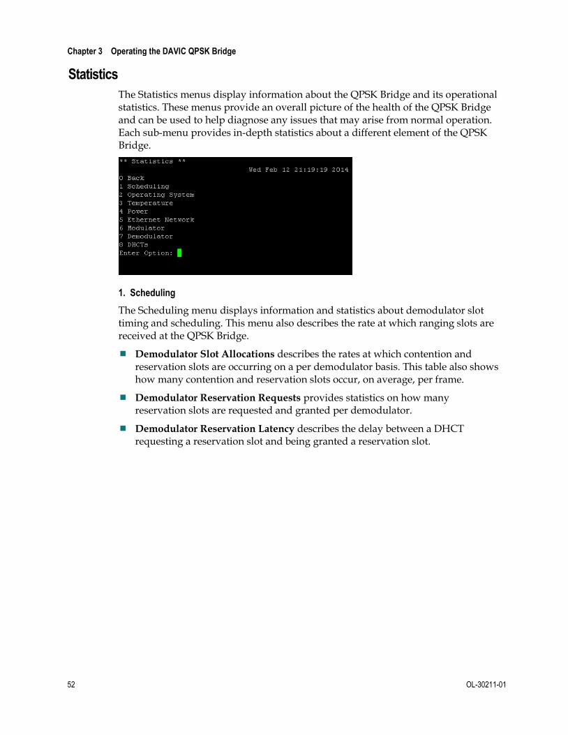
The Statistics menus display information about the QPSK Bridge and its operational statistics. These menus provide an overall picture of the health of the QPSK Bridge and can be used to help diagnose any issues that may arise from normal operation. Each sub-menu provides in-depth statistics about a different element of the QPSK Bridge.
1. Scheduling
The Scheduling menu displays information and statistics about demodulator slot timing and scheduling. This menu also describes the rate at which ranging slots are received at the QPSK Bridge.
Demodulator Slot Allocations describes the rates at which contention and reservation slots are occurring on a per demodulator basis. This table also shows how many contention and reservation slots occur, on average, per frame.
Demodulator Reservation Requests provides statistics on how many reservation slots are requested and granted per demodulator.
Demodulator Reservation Latency describes the delay between a DHCT requesting a reservation slot and being granted a reservation slot.

QPSK Bridge Shell Menu
OL-30211-01 53
2. Operating System
The Operating System menu displays tables containing system resource statistics, such as Disk, Memory, and CPU usage. There is also a Load table that displays the average system load and a count of the number of processes currently running on the QPSK Bridge.
Table Description
Disk Displays the amount of NVRAM system storage being used by the system, and how much is free.
Memory Displays the system RAM memory usage.
Load Displays the system load statistics and an active process count.
CPU Usage Displays CPU usage statistics by user, system, and idle.

Chapter 3 Operating the DAVIC QPSK Bridge
54 OL-30211-01
Table Description
LCD Button Presses Displays the number of times each of the LCD navigation buttons have been pressed.
3. Temperature
The Temperature statistics menu displays information about the system's temperature and related elements. This includes the fan speed of the three front fan modules and temperature statistics from the internal temperature sensors. The temperature statistics menu is shown in the following figure.

QPSK Bridge Shell Menu
OL-30211-01 55
4. Power
The Power statistics menu displays the input and output power statistics of the QPSK Bridge, including currents and voltages. The voltage rails are the internal voltages of the QPSK Bridge that are used to power the various components within the unit.

Chapter 3 Operating the DAVIC QPSK Bridge
56 OL-30211-01
5. Ethernet Network
The Ethernet Network statistics menu displays the total number of packets that are sent and received over the Ethernet Management interface, located on the rear panel of the QPSK Bridge. The receive (Rx) and transmit (Tx) errors can be useful in troubleshooting connectivity issues with the unit. The Ethernet Network Statistics menu is shown in the following figure:
6. Modulator
The Modulator statistics menu displays the health of the Low RF output port. It displays various statistics related to the functions of the QPSK Bridge. The following table describes the three tables located in this menu.
Table Description
Overview Total number of DHCTs connected to the QPSK Bridge.
The state of the Low QPSK modulator.
Notes:
– Good means that there are no known problems with the modulator.
– Not Present means that the system does not detect a modulator.
– Failover Event means that the modulator has internally detected a major problem.
– Muted means that the output of the modulator is muted and is no longer transmitting.
– Software Error means something went wrong contacting the modulator.
– General Error means that there is an unknown issue with the modulator.
Total number of Extended Super Frames sent to the DHCTs.

QPSK Bridge Shell Menu
OL-30211-01 57
Table Description
Transmitted Cells Total number of cells transmitted in the FDC.
The average number of cells transmitted in a 50 ms period calculated over a one minute window.
The peak number of cells transmitted in a 50 ms period over a one minute window.
The total number of cells dropped due to oversubscription of the FDC.
Transfer Rates Displays the total amount of data traffic as well as a breakdown of different data types transmitted from the DNCS to the DHCTs over the FDC.
7. Demodulator
The Demodulator Statistics menu displays information about the eight QPSK demodulators located on the rear panel of the QPSK Bridge. This menu provides information on each demodulator itself, as well as the DHCTs that are connected to the QPSK Bridge. Descriptions of each table located in this menu can be found below.
Total Received Cells – Provides in-depth statistics about the total number of cells received across all eight demodulators and includes a breakdown of all AAL5 errors, packet drops, and buffer overflows. In a healthy network, all values in this table should be close to zero, except the number of received cells.
Notes:
Unknown VPI – Packet received with unexpected VPI value, such as an STB not in the database. Cells discarded.
Number Received — Total number of cells received on all demodulators.
HEC Correctable Errors – Number of cells received with corrected HEC errors. Uncorrectable HEC cells are dropped.
HEC Uncorrectable Errors – Number of cells received with uncorrectable HEC errors.
LLDMA Packet Drops – Number of MAC packets received but discarded due to LLDMA buffer overflow.
Received Buffer Overflow Errors – Number of input ATM cells discarded due to input buffer overflow.
(AAL5) CRC Errors – Packet reassembly failed due to CRC error. Packet discarded.
(AAL5) Time-out Errors – Packet reassembly failed due to too long a spacing between received cells. Packet discarded.
(AAL5) Abort Errors – Packet reassembly failed due to receiving the AAL5 abort indicator. Packet discarded.

Chapter 3 Operating the DAVIC QPSK Bridge
58 OL-30211-01
(AAL5) Length Failure - Numbers of times a packets fails reassembly due to an incorrect length in the AAL5 trailer when reassembly is attempted. The packet is discarded.
Total AAL5 Errors — The sum of all AAL5 errors.
DHCTs – Provides a breakdown of the total number of DHCTs that are connected to each demodulator, with a further breakdown of how many DHCTs have their status pending. A DHCT with its status pending has not sent a status response to the QPSK Bridge.
Cell Counts – Shows the total number of cells, by demodulator, that have been received. A further breakdown of the number of peak, average, good, bad, and erroneous cells is also given.
Notes:
Peak - The highest number of cells received in a 50 ms window over the last 1 minute window.
Average - Total number of cells received in the last 1 minute window.
Bad - Number of cells received with an uncorrectable number of errors.
One Error - Number of cells received with one error corrected by FEC.
Two Errors - Number of cells received with two errors corrected by FEC.
Three Errors - Number of cells received with three errors corrected by FEC.
Total Good - Number of cells received with no errors.
Counts by Slot Type – Shows a breakdown of the total number of each type of cell that is received by each demodulator. This table also shows the total number of errors of each type of cell on a per demodulator basis.
Power and Timing – Shows the power and timing measurements for each demodulator.
Column Description
Demodulator ID Identifies each demodulator on the QPSK Bridge.
Last Power The power of the last cell received at the demodulator.
Current Average Power
The average power of all cells received.
Maximum Power in Last 24 H
The highest power level of any cell received within the last 24 hours.
Minimum Power in Last 24 H
The lowest power level of any cell received within the last 24 hours.
Last Arrival Time The amount of time after the start of the framing window at which the start of the last packet was received on the demodulator.
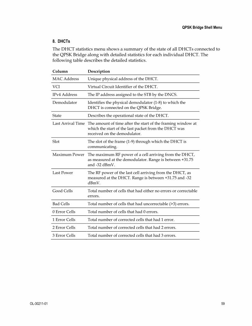
QPSK Bridge Shell Menu
OL-30211-01 59
8. DHCTs
The DHCT statistics menu shows a summary of the state of all DHCTs connected to the QPSK Bridge along with detailed statistics for each individual DHCT. The following table describes the detailed statistics.
Column Description
MAC Address Unique physical address of the DHCT.
VCI Virtual Circuit Identifier of the DHCT.
IPv4 Address The IP address assigned to the STB by the DNCS.
Demodulator Identifies the physical demodulator (1-8) to which the DHCT is connected on the QPSK Bridge.
State Describes the operational state of the DHCT.
Last Arrival Time The amount of time after the start of the framing window at which the start of the last packet from the DHCT was received on the demodulator.
Slot The slot of the frame (1-9) through which the DHCT is communicating.
Maximum Power The maximum RF power of a cell arriving from the DHCT, as measured at the demodulator. Range is between +31.75 and -32 dBmV.
Last Power The RF power of the last cell arriving from the DHCT, as measured at the DHCT. Range is between +31.75 and -32 dBmV.
Good Cells Total number of cells that had either no errors or correctable errors.
Bad Cells Total number of cells that had uncorrectable (>3) errors.
0 Error Cells Total number of cells that had 0 errors.
1 Error Cells Total number of corrected cells that had 1 error.
2 Error Cells Total number of corrected cells that had 2 errors.
3 Error Cells Total number of corrected cells that had 3 errors.

Chapter 3 Operating the DAVIC QPSK Bridge
60 OL-30211-01
QPSK Bridge Web Interface The Web Interface on the QPSK Bridge is a system of point-and-click menus used to view system information and statistics. The information in these menus is the same as the information that is available through the Shell menu; however, it is presented in a more user-friendly manner.
While using the Web interface, you cannot configure the QPSK Bridge as can be done with the Shell menu. Basic maintenance functions can be performed, but that is the extent of user interaction with the device. This section will describe the Web Interface, its layout, and its functionality.
Important: Prior to using the Web Interface, ensure that HTTP is enabled. Choose Configuration > Services.
Connecting to the Web Interface
To connect to the QPSK Bridge’s Web interface, point your web browser to the IP address of the QPSK Bridge.
Note: Supported Web browsers are Mozilla Firefox Versions 14 and 15, Microsoft Internet Explorer Versions 9, and Google Chrome versions 21 and 22. Newer versions of these Web browsers can also be used.
The QPSK Bridge uses a security certificate to authenticate itself. Depending upon the web browser used to connect to the QPSK Bridge, different security warnings may appear. You will be asked to accept the QPSK Bridge’s security certificate in order to continue and access the Web Interface.
An example of the FireFox security warning follows:

QPSK Bridge Web Interface
OL-30211-01 61
After clicking Add Exception…, another window appears. Click Confirm Security Exception to proceed to the login window, as shown in the following figure:
The login window will authenticate that you have permission to access the QPSK Bridge's data and statistics. The credentials (username and password) are the same credentials that are used to access the QPSK Bridge via the Shell menu. The default login is D9485_admin and the password is a user-configured password.
Important: Prior to accessing the Web Interface, initial login must occur through the Shell menu so that the default password can be changed and the web service enabled. See Initial Login (on page 35).

Chapter 3 Operating the DAVIC QPSK Bridge
62 OL-30211-01
Using the Web Interface
Once successfully logged in to the QPSK Web interface, you are presented with the System Information menu as shown in the following figure:
The Web interface is broken into two main areas:
1 Navigation Pane – Provides a tool for navigating the Web interface to obtain information about the QPSK Bridge.
2 Information Pane – Displays information relevant to the menu you have selected in the QPSK Bridge Navigation Pane.
Navigation Pane
The Navigation Pane can also be broken into different areas, as shown in the following figure:

QPSK Bridge Web Interface
OL-30211-01 63
Area Name Description
1 Cisco device information
Shows the Cisco device model number and logo. Clicking on the Cisco logo will take you to the Cisco.com homepage.
2 Data and Statistics Menus
These menus display various types of information about the QPSK Bridge. Clicking on a menu will produce a drop-down list with more options.
3 Chassis Name Displays the chassis name you set up.
4 Quick Buttons Provides a quick access to specific information and also the current time and date.
Provides quick access to the Current Alarms menu
Provides a pop-up list showing technical support information.
Provides quick access to the Debug Dump generation menu.
Provides quick access to the Maintenance LED menu.
Information Pane
The Information Pane displays the data within each of the Data and Statistics menus.
Following are descriptions of the four areas of the information pane:
1 Menu Path – This path helps you locate where within the menus the information in area 2 is being displayed.
2 Information and Statistics – This is the main area of the Information Pane. It displays all of the data/statistics for the currently selected menu. This area may contain tools for sorting and filtering the data displayed.

Chapter 3 Operating the DAVIC QPSK Bridge
64 OL-30211-01
3 Sort – Clicking the top of some columns will sort that column. You can sort in either ascending or descending order. Not all menus have columns that can be sorted.
4 Search Filter – In this field, you can search for a specific string of text. The results from any search will automatically be displayed as you type in the entry. Not all menus contain the search option.
Data and Statistics Menus
The menu system in the Web interface follows the same structure as the menu system for the Shell menu. All of the information displayed in the Web interface is pulled from the same locations within the QPSK Bridge as the Shell menu. For additional information on the Data and Statistics menu, see Statistics (on page 52).
Note: The SNMP MIB file for the QPSK Bridge can be downloaded at any time by choosing Configuration > SNMP.
Maintenance
The Maintenance menu in the Web interface is very limited in the actions that can be performed. There are two sub-menus under the Maintenance menu:
MAINT LED
Debug Dump
Both sub-menus perform the same function as their Shell menu counterparts.
MAINT LED
The maintenance LED is an LED located on the rear of the QPSK Bridge and is used to help locate a specific QPSK Bridge when many are racked together. This is typically turned on to identify a unit that requires maintenance to be performed (for example, power supply or fan replacement). The maintenance LED can be turned on and off through the WebUI by following these steps:
1 Select the MAINT LED State to which you wish to set the LED from the drop-down list.
2 Click Submit.

QPSK Bridge Web Interface
OL-30211-01 65
After you click Submit, a green banner indicator, as seen in the following figure, should appear to indicate that the command was successful. A log message will also appear to show that the MAINT LED state was set to ‘ON’.
Debug Dump
A debug dump that is generated through the Web interface provides the exact same information as a debug dump generated through the Shell menu. It is a snapshot of the state of the QPSK Bridge and includes all alarms, log messages, and other detailed information about the operational state of the device. For quick access to a debug dump, the Web interface is often the best option.
To obtain a debug dump through the Web Interface:
1 Generate a new debug dump by clicking New.
Note: The Debug Dump State will change multiple times until the debug dump has been generated. This takes a few minutes.
2 Download the debug dump from the QPSK Bridge by clicking on the web link provided next to the Download heading. The file is a tarball (.tgz) and will require an archiving tool to decompress.
Note: Not all files within the debug dump will be able to be opened and read. Some files are encrypted for Cisco Services' use only.
After a debug dump has been successfully generated, there will be a timestamp of when the debug dump was Last Completed, and a green banner at the top of the page indicating that the changes have been successfully submitted.

Chapter 3 Operating the DAVIC QPSK Bridge
66 OL-30211-01
The following figure shows the outcome of a successful web interface debug dump:

LCD Interface
OL-30211-01 67
LCD Interface The LCD interface, located on the front of the QPSK Bridge, is a digital LCD display with accompanying navigation buttons. It provides access to a series of menus used to gather information and change configuration settings on the QPSK Bridge. Changes made through the LCD interface are instantaneous and require physical access to the device. To prevent access, you can lock the LCD interface through the Shell menu.
Using the LCD Interface
The LCD interface is shown in the following figure. It consists of a 192 x 32 pixel screen and a directional button pad with an Enter button located in the center.
The LCD interface is navigated with the directional button pad and the Enter button. Status items are broken down into related categories and some can be modified using the directional buttons. The directional buttons allow you to scroll through a list of selectable items or trigger an event within the system. Any changes that you make using the front panel are automatically saved.
There are three types of nodes in the LCD menu system:
Menu Node – Top level menu that provides access to other menus, display nodes, and configuration nodes.
Display Node – Displays system configuration information, but cannot be modified through the LCD interface.
Configure Node – Allows you to make configuration changes.

Chapter 3 Operating the DAVIC QPSK Bridge
68 OL-30211-01
Navigational Chart
Following is a high-level navigational chart for the LCD Interface menu system. The legend in the following figure shows which blocks (or groups of blocks) are which types of nodes in the navigational chart:
The following table describes the actions of the directional pad for each node type:
Node Left/Right Arrows Up/Down Arrows Enter/OK
Menu Move to previous/next heading in same menu level.
Traverse up/down in menu hierarchy. Moving up from the top-most level of the menu hierarchy will enter the default display. Moving down from a “leaf” node will enter the display nodes for the current view.
Same as Down key.
Display Return to Menu navigation
Move to previous/next item in display node list.
Enters CONFIG mode for the selected display node, if applicable.
Configure Return to DISPLAY mode without committing changes
Select previous/next allowable value for the configurable field.
Start configuration action or indicate acceptance of change of configuration.
When on a configure node, the configuration list, once selected by the Enter key, allows you to scroll through a list, using the and keys, of configuration values for the node. If a new value is desired, the Enter key is pressed while the new value is displayed and the focus returns to the display item name. To back out of selecting a new value the or key can be used to return focus to the display item name. Each Modulator and Demodulator has its own menu heading, and its numeric identifier will appear in each associated Display node.

LCD Interface
OL-30211-01 69
Status Display Node
The Status Display node is the QPSK Bridge’s default LCD screen and displays basic information about the QPSK Bridge. The Status Display is shown in the following figure:
RF Node
The RF node allows you to change the RF characteristics of the modulators and demodulators on the QPSK Bridge. To access this node, press the and arrow keys until RF shows on the LCD. Then, press Enter.
From this top Menu node, you can scroll through the different RF characteristics to configure the following nodes:
Modulator [1…2] Node – Allows you to configure the Low RF output port.
Node Node Type Description Value
RF Output Port
Display Displays the selected RF Output port.
Low only
RF Freq Configure Allows you to set the RF Output Frequency.
70 – 130 MHz
0.25 MHz steps
RF Power
Configure Allows you to set the RF Output Power.
50 – 60 dBmV
1 dBmV steps

Chapter 3 Operating the DAVIC QPSK Bridge
70 OL-30211-01
Node Node Type Description Value
RF Enabled
Configure Allows you to enable / disable the Low RF Output port.
Enable – Disable
CW Mode
Configure Allows you to enable / disable CW Mode.
Enable – Disable
Demodulator [1…8] Node – Allows you to configure demodulators 1 – 8.
Node Node Type Description Value
Demodulator Display Displays the selected demodulator.
1 – 8
Input Frequency
Configure Allows you to configure the selected demodulator input frequency.
5 – 42 MHz
1 MHz steps
Attenuation Configure Allows you to set the attenuation at the selected demodulator.
0, 8, 16, 24 dB
Input RSSI Display Displays the signal strength of the last received cell on the selected demodulator.
dB
Last Arrival Time
Display Displays the number of nanoseconds since the start of the frame that the last cell on the selected demodulator arrived.
0 – 999999 ns
Slot Allocation Display Displays the total number of receive time slots used on the demodulator, relative to the total number of receive time slots available.
percentage
Max Node Distance Node – Allows you to configure the maximum node distance, that is, the furthest distance from the QPSK Bridge to a group of DHCTs assigned to a demodulator. The Max Node Distance is configurable between 0 – 248 km, with a 31 km step size.

LCD Interface
OL-30211-01 71
System Node
The System node displays information about the QPSK Bridge itself, its IP network, Craft port, and supply voltages. The baud rate for the Craft port is the only element that can be configured from within this node. To access this node, press the and arrow keys until System shows on the LCD. Then, press Enter. The following figure provides a closer look at this node:
Info Node – Displays system information about the QPSK Bridge.
Node Node Type Description Value
System Release
Display Displays the system software version currently running on the QPSK Bridge.
1_X_Y
Model Number
Display Displays the model number of the QPSK Bridge.
D9485
Product ID Display Displays the product ID of the QPSK Bridge.
D9485
Network Node – Displays basic network information about the QPSK Bridge.
Node Node Type Description Value
IP Display Displays the QPSK Bridge’s IP address.
www.xxx.yyy.zzz
MAC Display Displays the QPSK Bridge’s MAC address.
aa:bb:cc:dd:ee:ff

Chapter 3 Operating the DAVIC QPSK Bridge
72 OL-30211-01
CRAFT Port Node – Displays the settings required to connect to the QPSK Bridge’s RS-232 CRAFT port.
Node Node Type Description Value
Baud Rate
Configure Displays a user-configurable baud rate.
9600, 19200, 38400, 57600, 115200
Data Bits
Display Displays the number of data bits.
8
Stop Bits
Display Displays the number of stop bits.
1
Parity Display Displays if there is not a parity bit.
None
Supply Voltages Node – Displays all of the QPSK Bridge’s internal voltage rails and power supply voltages.
Node Node Type
Description Value
1.0 V Rail Display Displays the current 1.0 V rail voltage.
~ 1000 mV
1.2 V Rail Display Displays the current 1.2 V rail voltage.
~ 1200 mV
1.8 V Rail Display Displays the current 1.8 V rail voltage.
~ 1800 mV
2.5 V Rail Display Displays the current 2.5 V rail voltage.
~ 2500 mV
3.3 V Rail Display Displays the current 3.3 V rail voltage.
~ 3300 mV
5.0 V Rail Display Displays the current 5.0 V rail voltage.
~ 5000 mV
6.0 V Rail Display Displays the current 6.0 V rail voltage.
~ 6000 mV
PSU 1 Out Display Displays the DC output voltage of power supply #1
~ 120000 mV
PSU 1 In Display Displays the AC input voltage of power supply #1
~ 120 V
PSU 2 Out Display Displays the DC output voltage of power supply #2
~ 120000 mV
PSU 2 In Display Displays the AC input voltage of power supply #2
~ 120 V

LCD Interface
OL-30211-01 73
Alarms Node
The Alarms node lists all current active alarms present on the QPSK Bridge. This node will display when the alarm was raised, the severity of the alarm, the alarm ID, and a short description of the alarm. Use the and buttons to scroll through the active alarms. An example of the Alarms node LCD screen follows:
Admin Node
The Admin node allows you to perform a few major administration functions on the QPSK Bridge. To access this node, press the and arrow keys until Admin
shows on the LCD, and then press Enter. The following figure provides a closer look at this node.
Within this node, you can access two configure nodes:
Set a One-Time Password (OTP)
This resets the D9485_admin password to a provided random character password. To reset the password, follow these steps.
1 Navigate to the OTP node.
2 Press Enter and then or to select Set OTP.
3 Press Enter and the OTP is displayed.
This password can only be entered once, at which time you will be asked to change the password. To use this password, you must log into the Shell menu. See Initial Login (on page 35) for more details on setting a password.
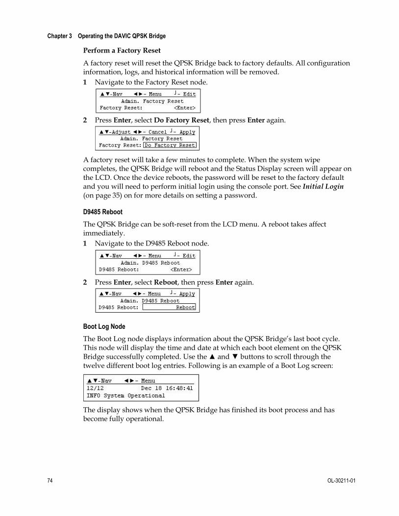
Chapter 3 Operating the DAVIC QPSK Bridge
74 OL-30211-01
Perform a Factory Reset
A factory reset will reset the QPSK Bridge back to factory defaults. All configuration information, logs, and historical information will be removed.
1 Navigate to the Factory Reset node.
2 Press Enter, select Do Factory Reset, then press Enter again.
A factory reset will take a few minutes to complete. When the system wipe completes, the QPSK Bridge will reboot and the Status Display screen will appear on the LCD. Once the device reboots, the password will be reset to the factory default and you will need to perform initial login using the console port. See Initial Login (on page 35) on for more details on setting a password.
D9485 Reboot
The QPSK Bridge can be soft-reset from the LCD menu. A reboot takes affect immediately.
1 Navigate to the D9485 Reboot node.
2 Press Enter, select Reboot, then press Enter again.
Boot Log Node
The Boot Log node displays information about the QPSK Bridge’s last boot cycle. This node will display the time and date at which each boot element on the QPSK Bridge successfully completed. Use the and buttons to scroll through the twelve different boot log entries. Following is an example of a Boot Log screen:
The display shows when the QPSK Bridge has finished its boot process and has become fully operational.

Upgrading the QPSK Bridge
OL-30211-01 75
Upgrading the QPSK Bridge Upgrading the QPSK Bridge can be accomplished both remotely and while directly connected with a PC. Remote upgrades are achieved via a TFTP/HTTP download of the upgrade file over the Ethernet port. Direct upgrades are achieved through a Zmodem transfer over the RS-232 console port. Using either method, the system will automatically install the upgrade once the file has completed downloading on the QPSK Bridge and then reboot. Normal operation will persist while the upgrade file is being downloaded and installed.
The QPSK Bridge contains two complete software images: the active image and a backup image. If the device is running the active image, it will upgrade the backup image. Once the backup image has been upgraded, the system will reboot into the backup image, thus becoming the new active image. The old active image will become the new backup image.
The QPSK Bridge allows you to upgrade/ downgrade to versions of software that are older/newer than the currently running version. Caution should be taken while applying a new upgrade file to ensure that the software changes will not impact desired operation.
A system upgrade can be aborted at any time while the file is being downloaded or installed. If there is a problem with an upgrade, the Result in the System Upgrade table will show as Failed, an alarm will be raised, and log messages will be created. When troubleshooting an upgrade failure, the logs can provide insight as to the reason.
Important: An upgrade filename must start with the text “D9485”. An upgrade file that fails to follow this naming convention will be rejected by the QPSK Bridge.
Note: While using external routing equipment in association with the D9485 QPSK Bridge, ensure that the external routing equipment is set to autonegotiate mode. Using half or full duplex mode may cause problems while communicating with the device.
TFTP/HTTP Transfer
The QPSK Bridge can also be upgraded by initiating a TFTP/HTTP file transfer to download an upgrade file from a TFTP server. The upgrade can be initiated by either adding upgrade information to the configuration file, or by manually initiating an upgrade through the Shell menu. In this way, the QPSK Bridge will download the upgrade file, and then apply it before automatically rebooting.
Shell Menu
1 Choose Maintenance > Upgrade and select 1 - System Upgrade.
2 Enter the TFTP server or HTTP address where the upgrade file is located.

Chapter 3 Operating the DAVIC QPSK Bridge
76 OL-30211-01
3 Enter the entire path / filename of the upgrade file and press Enter to begin upgrade.
Important: When identifying which upgrade file to use, the entire path, filename, and extension are required.
Example: /tftpboot/Cisco/D9485/Upgrades/D9485_1_2_16.bin.signed
Result: The upgrade will begin and the Result will indicate the status of the upgrade.
In Progress indicates that the QPSK Bridge was able to use the information provided to begin downloading the upgrade file
Failure indicates that there was an error in downloading the upgrade file. Check the alarms and logs to determine the cause of the failure.
Note: When the upgrade is finished, the QPSK will automatically reboot and the current SSH connection is closed.
Upgrading the QPSK Bridge
OL-30211-01 77
4 After an upgrade has completed (5 - 10 minutes), verify that the unit has successfully upgraded to the new software version by verifying the System
Release in the System Information menu (Status > System Information).
Configuration File Upgrade
On every boot, the QPSK Bridge downloads and loads a configuration file (if configured on the DNCS). This configuration file can tell the QPSK Bridge to perform a system upgrade by indicating a TFTP/HTTP server address to go to and a file to download. The upgrade will be performed in the background and the system will reboot automatically when complete. For more information on the configuration file, see the online help for the QPSK, as well as QPSK Bridge Configuration File (on page 105).
Important: When performing an upgrade through the Shell menu, ensure that the configuration file does not indicate an upgrade that conflicts with the newly upgraded file. If so, the QPSK Bridge will upgrade to the file indicated in the configuration file, upon boot.
Zmodem Transfer
Note: Due to the nature of the Zmodem file transfer method, this is the least desirable method of upgrading.
Perform the Zmodem upgrade file transfer through the shell menu by using the RS-232 serial port. To access this upgrade option you must use a terminal program capable of sending a file using z-mode, such as TeraTerm or HyperTerminal.
Notes:
A Linux PC with minicom is recommended for performing Zmodem upgrades. If you are using a Windows PC, TeraTerm is recommended.
A Zmodem transfer can take anywhere from 20 minutes to 2 hours. The QPSK Bridge cannot be used during this time. If a transfer error occurs, an error message will be displayed in the terminal window.
1 Connect to the QPSK Bridge’s serial port (see Direct Connectivity (on page 33)).
2 Enter the upgrade menu, in Maintenance (on page 47), in the Shell menu.
3 Choose option 2, Start Zmodem Upgrade, and then enter y to start the transfer.
Note: Once the transfer has started, the shell menu will not be accessible.
4 Select the upgrade file you wish to transfer and begin the transfer.
Notes:
In TeraTerm, choose File > Transfer > ZMODEM > Send. Select the upgrade file and click Open.
Once the transfer has been started (Step 3), you will have about one minute to select the upgrade file and begin the transfer. Otherwise the transfer will time out. The sooner the Zmodem transfer can be started, the greater chance you have of a successful upgrade.

Chapter 3 Operating the DAVIC QPSK Bridge
78 OL-30211-01
To decrease the time required to make a Zmodem transfer, try increasing the baud rate. The baud rate can be increased on both the QPSK Bridge and the terminal program. See Chassis under Configuration (on page 39) for more information on how to change the baud rate.
5 Once the transfer is complete, the QPSK Bridge will automatically install the upgrade and reboot.
Note: Repeat Steps 3 and 4 if the Zmodem transfer fails.

OL-30211-01 79
Introduction
The standard mode of operation for the QPSK data link requires the QPSK modulator and demodulator hardware to be physically located near the geographic center of the desired coverage zone. The operation of the system then allows a radius of operation of about 70 KM from the site of the hardware in the hub.
There are a number of applications that need or desire to physically locate the QPSK hardware in the headend (or some location other than the center of the coverage zone) and yet provide QPSK coverage to set tops that are more than 70 KM from the headend site. In response to this need, Cisco has developed a software design modification for the D9485 QPSK Bridge to allow the QPSK modulator/demodulator hardware to be located in the headend and provide QPSK data services to a remote hub at a distance of up to 252 KM. This chapter provides application information to assure successful implementation of this feature.
4 Chapter 4 Using the Delay Mode in the QPSK Data Link
In This Chapter
Feature Implementation ....................................................................... 80
Delay Mode Setup and Operation ...................................................... 81
Design Examples ................................................................................... 83

Chapter 4 Using the Delay Mode in the QPSK Data Link
80 OL-30211-01
Feature Implementation This feature has been implemented by introducing a delay in the DAVIC frame reference timing the QPSK modulator provides to the QPSK demodulator. This timing delay provides additional time in the DAVIC signal framing to compensate for the time required for the QPSK signal to propagate through the optical distribution cable and return back to the QPSK demodulator. This modification allows for nine different values of propagation delay to be programmed into the QPSK modulator via the front panel. The delay value options are specified as optical propagation distance equivalents of the delay time programmed in the QPSK modulator. The distance increment equivalents to the delay time are calculated by multiplying the delay time by the distance a signal can travel through an optical fiber, having an assumed propagation velocity factor of 70 percent of the speed of light. The propagation distance choices are offered in 31.5 KM increments (one way), starting with 31.5 KM and up to 252 KM. The actual timing delay increments occur in integer multiples of 300 microseconds.
When the delay feature is activated, the QPSK expects an optical transmission delay equal to or greater than the distance value programmed into the QPSK modulator. The QPSK system continues to have a zero to 70 KM ranging distance for set tops in the delay mode. Therefore, the maximum distance a set top can be located from the headend in the delay mode is the sum of the programmed delay distance plus the 70 KM ranging distance. The action of the timing delay causes the apparent “zero ranging distance” to occur at the optical cable distance physically equal to the delay (one-way) distance programmed in the modulator. If the optical cable is longer than the programmed distance value, the ranging radius will be reduced by the excess optical cable length. If the optical cable is shorter than the programmed distance value, the set tops within a radius equal to the distance the optical cable is shorter than the programmed distance value will not be able to complete a ranging sequence.

Delay Mode Setup and Operation
OL-30211-01 81
Delay Mode Setup and Operation 1 Configure the network per Application Rules (on page 81).
2 Download Version 1.2.16+ D9485 QPSK modulator software on to the QPSK modulator
3 Choose Delay Mode from the front panel options menu. After choosing this option, the QPSK will force another download of the QPSK application code. Wait for the new application download (now configured for delay mode) to complete.
4 Choose a value of optical cable length from the front panel options menu equal to or less than the sum of actual optical cable length used for the distribution to the remote hub, plus the minimum optical cable length used in the HFC network from the hub. Adjust the setting if the cable propagation velocity factor is not equal to 70 percent.
5 Place a set top at the closest possible location to where the HFC network transitions from optics to cable. Check the delay time on the set top diagnostic screen. The delay value should not be less than 200 microseconds. Place a set top in the location with the maximum possible cable distance from the cable breakout point in the HFC network. Check the delay time at the set top diagnostic screen. The delay value should not exceed 760 microseconds.
6 If the delay values do not fall within the 200 microseconds and 760 microseconds delay time bounds, the set tops in the affected region will not provide reliable ranging performance. Either the programmed delay value or the network must be adjusted to keep the delay times at the test boundaries within the specified limits.
Application Rules
Transport distances are in integer multiples of 31.5 KM, up to maximum of 252 KM.
The programmed delay distance should be chosen to be equal to or less than the sum of the transport cable to the hub, plus the shortest optical cable distance on any of the attached nodes.
The ranging radius is 0 to 70 KM, with 0 KM set at the programmed cable length.
All demodulators are delayed by the same value programmed in the QPSK modulator.
If the optical cable length exceeds the programmed distance value, the ranging radius shrinks.
If the optical cable length is less than the programmed distance value, close-in set tops will not range.

Chapter 4 Using the Delay Mode in the QPSK Data Link
82 OL-30211-01
Variations in the optical cable length branching from the hub will cause a reduction in the ranging radius.
If an errant distance value is programmed in the QPSK modulator, a new, corrected value can be entered, and the set tops will re-range after a ten-minute timeout. Or, the operator can force a set top reboot.
In a pinch, coverage radii can be extended by matching the optical cable distance to the programmed distance value.

Design Examples
OL-30211-01 83
Design Examples
Matched Cable Length and Delay
The design example, shown in the following figure, is an application example of the QPSK modem in a matched configuration. The optical cable distance is equal to the programmed delay distance and all of the node distances from the hub have equal lengths.
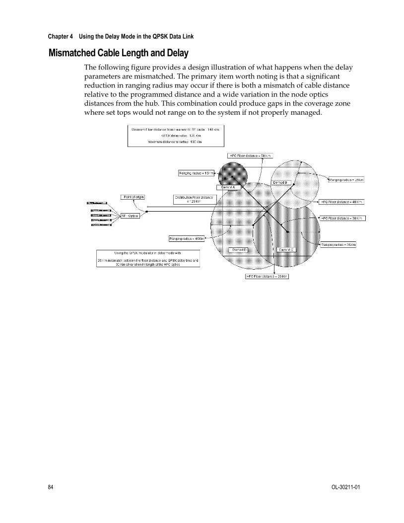
Chapter 4 Using the Delay Mode in the QPSK Data Link
84 OL-30211-01
Mismatched Cable Length and Delay
The following figure provides a design illustration of what happens when the delay parameters are mismatched. The primary item worth noting is that a significant reduction in ranging radius may occur if there is both a mismatch of cable distance relative to the programmed distance and a wide variation in the node optics distances from the hub. This combination could produce gaps in the coverage zone where set tops would not range on to the system if not properly managed.

OL-30211-01 85
Introduction
This chapter provides routine maintenance information, general troubleshooting guidelines, and explanations of major, minor, and status alarm conditions. This chapter also includes instructions for assessing alarm conditions. An alarm troubleshooting table, arranged alphabetically according to an alarm’s front panel LCD message, is included along with additional information for resolving alarm conditions.
5 Chapter 5 Troubleshooting the DAVIC QPSK Bridge
In This Chapter
Routine Maintenance............................................................................ 86
General Troubleshooting Guidelines ................................................. 88
Troubleshoot Alarms ............................................................................ 89

Chapter 5 Troubleshooting the DAVIC QPSK Bridge
86 OL-30211-01
Routine Maintenance Performing routine maintenance ensures proper functionality of the QPSK Bridge and helps in trouble-free operation. This section describes important maintenance procedures.
WARNING:
Only qualified personnel should attempt maintenance and service of the QPSK Bridge.
Quarterly Visual Inspection
The QPSK Bridge can operate unattended for extended periods of time. If the QPSK Bridge is operating normally, do not make any adjustments. However, do conduct a visual inspection at least once every four months.
Check the following items during a visual inspection:
Cables and connectors — Make sure that all cables are connected properly and that all retaining screws are tight. Inspect cables for stress and chafing.
Cover and back panel — If necessary, clean the cover and back panel with a soft cloth dampened with a mild detergent solution.
Cooling fan and intakes — Check the cooling fans on the front panel and the outtake vents on the rear panel for excessive lint or dust buildup. Remove the lint and dust from the fans and the outtake vents using a damp cloth or a small hand vacuum.
LEDs — Make sure that all LEDs are indicating normal status.
Replacing the Fan
This section provides instructions for replacing the cooling fan unit on the QPSK Bridge. The QPSK modulator has three cooling fans located behind the cover on the front of the unit.
Follow these steps to replace the cooling fan on the front panel of the QPSK Bridge.
1 Power off the QPSK Bridge. While this step is not necessary due to the fans being hot-swappable, it is nonetheless recommended. If replacing more than one fan module, only replace one cooling fan at a time to ensure that the unit does not overheat.
2 Remove the front panel cover by removing the two thumb screws located at the sides of the cover.
Note: The cover is attached to the chassis by a connecting wire. It is OK to let the cover hang while changing the chassis, but do not hang anything from it.

Routine Maintenance
OL-30211-01 87
3 On the front panel of the QPSK Bridge, unplug the fan from the connector.
Note: Needle-nose pliers may be required to reach the connector.
4 Remove the retaining screws using a Phillips screwdriver and set the non-functioning fan and screws aside.
Note: Be sure not to drop or misplace the screws. You will need them to replace the fan.
5 Attach the replacement fan to the back panel using the same screws you removed, making sure that you orient the fan so that the airflow blows inward.
Note: Be sure to use a torque of approximately 4-6 in./lb.
6 Plug the replacement fan into the power connector provided on the front panel.
7 Power on the QPSK Bridge (if powered off).
8 Verify that the replacement fan is operating correctly. If the replacement fan does not operate correctly, contact Cisco Services for assistance.
Replacing a Power Supply
This section describes how to replace a power supply on the QPSK Bridge. The QPSK Bridge contains two field-replaceable and hot-swappable power supplies. Each power supply is independent and only one supply is required for the QPSK Bridge to function properly.
CAUTION:
Avoid damage to this product! Your warranty is void if you attempt to operate this product with non-genuine replacement parts.
1 Remove the power cable from the power supply you wish to replace.
Note: If only one power supply is present, removing power will turn off the QPSK Bridge.
2 Using a Phillips-head screwdriver, remove the two captive retaining screws securing the power supply to the QPSK Bridge chassis.
3 Remove the old power supply from the chassis by pulling on the handle.
4 Insert the new power supply into the empty power supply slot and use the handle to guide the power supply fully into its slot.
Note: Extra force may be needed to properly seat the power supply with the chassis power connector.
5 Secure the new power supply to the chassis by tightening the two captive retaining screws.
6 Apply power to the new power supply by inserting the power cord connector into the power supply.

Chapter 5 Troubleshooting the DAVIC QPSK Bridge
88 OL-30211-01
General Troubleshooting Guidelines
Introduction
This section describes major, minor, and status alarms. In addition, this section explains how to access and read the alarms that display on the front panel LCD of the QPSK Bridge. If the QPSK Bridge indicates an alarm, check for false alarms, check the power supply, and/or follow the guidelines for troubleshooting major and minor alarms.
Checking AC Power
If the QPSK Bridge does not power up and the LEDs are either not lit or display red, this indicates a faulty power supply or power supply connection.
Follow these steps to determine whether a power problem is causing a power alarm.
1 Verify that the power wires and/or power cords are firmly connected in the QPSK Bridge and at the power outlet. Replace/reconnect the power wires or cords if necessary.
2 Verify that the outlet is supplying the proper voltage.
3 If the QPSK Bridge still indicates a power alarm, one or more power supplies may be defective.
a Attempt to power the QPSK Bridge with each single power supply individually to determine if the problem exists with only one supply.
b Each power supply contains an internal fan. If the fan is running and the power supply otherwise appears to be operating correctly, it may indicate an internal problem in the QPSK Bridge.

Troubleshoot Alarms
OL-30211-01 89
Troubleshoot Alarms
List of Alarms
When there is an alarm condition on the QPSK Bridge, the front panel display indicates which alarm condition is active and the ALARM indicator LED will be illuminated. An alarm Alarm Text message displays on the second line of the display, briefly describing which alarm condition is active. See Alarms Node under LCD Interface (on page 67) for additional information. Also, a list of all active alarms can be found in both the QPSK Bridge Shell Menu (on page 34) and the QPSK Bridge Web Interface (on page 60).
Each alarm’s Alarm Text will begin with the alarm ID – a unique identifier (e.g., 0x50010812). Use the alarm ID and the table below to quickly gain additional insight into what may be causing the alarm to rise. Many of the alarms on the QPSK Bridge can be raised for multiple reasons, and often additional investigation will be required to find the cause, and thus the resolution, of any particular alarm.
Important: The Alarms table in this section should only be used as a guideline to help troubleshoot and resolve alarm conditions. If an alarm cannot be resolved, contact Cisco Services.
All alarms on the QPSK Bridge are assigned a priority level. Each priority level has an associated Alarm LED color. Below are the different priority levels in order of severity (most severe to least severe) and their associated Alarm LED colors.
Priority Level
Associated LED Color
CRITICAL RED
MAJOR RED
MINOR YELLOW
STATUS OFF
The highest alarm priority level will always be indicated by the Alarm LED. For more information on configuring SNMP Trap receivers, see the sample configuration file in QPSK Bridge Configuration File (on page 105).

Chapter 5 Troubleshooting the DAVIC QPSK Bridge
90 OL-30211-01
Note: All alarms in the Alarms and Events List, which follows, are also sent as SNMP traps.
Alarms and Events List
Alarm Text Priority Associated LED
Description Resolution
Group sys_maint
0x50010812 - Maintenance mode activated.
STATUS MAINT_LED
Maintenance LED has been turned on
Group sys_sw
0x5001080D - Test mode enabled.
MINOR Yellow Test Mode has been enabled.
0x50010400 - System software out of memory.
MAJOR Red QPSK Bridge has run out of system memory.
0x5001082B - Customer-specific data deleted.
MINOR Yellow All user data has been removed. QPSK Bridge is reset to factory default configuration.
0x5001082D - Customer logs deleted.
MINOR Yellow All system, RPC, and DHCT log messages have been deleted.
Group sys_passwd
0x50010825 - Password changed via Front Panel.
STATUS None User has set a OTP for the QPSK Bridge through front panel LCD.
0x5001082C - Failed to set Admin Default Password.
MAJOR Red User has not set a D9485_admin password.
Set the D9485_admin password.
Group sys_upgrade
0x50010814 - Upgrade in progress (arguments: %s).
STATUS None Upgrade is in progress.

Troubleshoot Alarms
OL-30211-01 91
Alarm Text Priority Associated LED
Description Resolution
0x50010815 - Upgrade success. Reboot required.
STATUS None Upgrade was successful. Requires reboot.
0x5001010A - Upgrade file download has started.
STATUS None QPSK Bridge has started an upgrade by downloading the new firmware.
0x50010104 - Failed to open upgrade file (%s).
MINOR Yellow Could not open downloaded software upgrade. Corrupted data.
%s:
Name not prefixed with 'D9485'
Invalid parameters of failed transfer
aborted
Check the file name to ensure it begins with D9485. Ensure that the upgrade file exists on the TFTP server.
0x50010105 - Failed to read upgrade file (%s).
MINOR Yellow After being downloaded and opened, the file was not able to be read.
%s:
package verification
package extraction
upgrader verification
aborted
Confirm that the upgrade file is not corrupt on the TFTP server. Compare the MD5 sum to the expected value.
0x5001010B - Upgrade programming started.
STATUS None Upgrade has downloaded and started programming.

Chapter 5 Troubleshooting the DAVIC QPSK Bridge
92 OL-30211-01
Alarm Text Priority Associated LED
Description Resolution
0x50010106 - Failed to program the upgrade.
MAJOR Red An error occurred that prevented the QPSK Bridge from completing the programming of the newly downloaded firmware.
Re-apply upgrade.
0x50010808 - Failed to boot the upgrade (%s).
MAJOR Red New software was downloaded and programmed, but failed to reboot and load upgrade image.
%s:
run-time: <running release version> doesn't match: <Supposes active release>
Check/replace your upgrade file and try to re-apply the upgrade.
Group sys_temp
0x50010826 - Processor board temperature threshold exceeded (%s).
MAJOR Red Safe processor board temperature exceeded.
Check the ambient room temperature and adjust if necessary. Check fans for proper operation.
0x50010827 - Ambient temperature threshold exceeded (%s).
MAJOR Red Safe internal ambient air temperature exceeded.
Check the ambient room temperature and adjust if necessary. Check fans for proper operation.
0x50010828 - Fan temperature threshold exceeded (%s).
MAJOR Red Safe internal ambient air temperature for fan controller board exceeded.
Check the ambient room temperature and adjust if necessary. Check fans for proper operation.
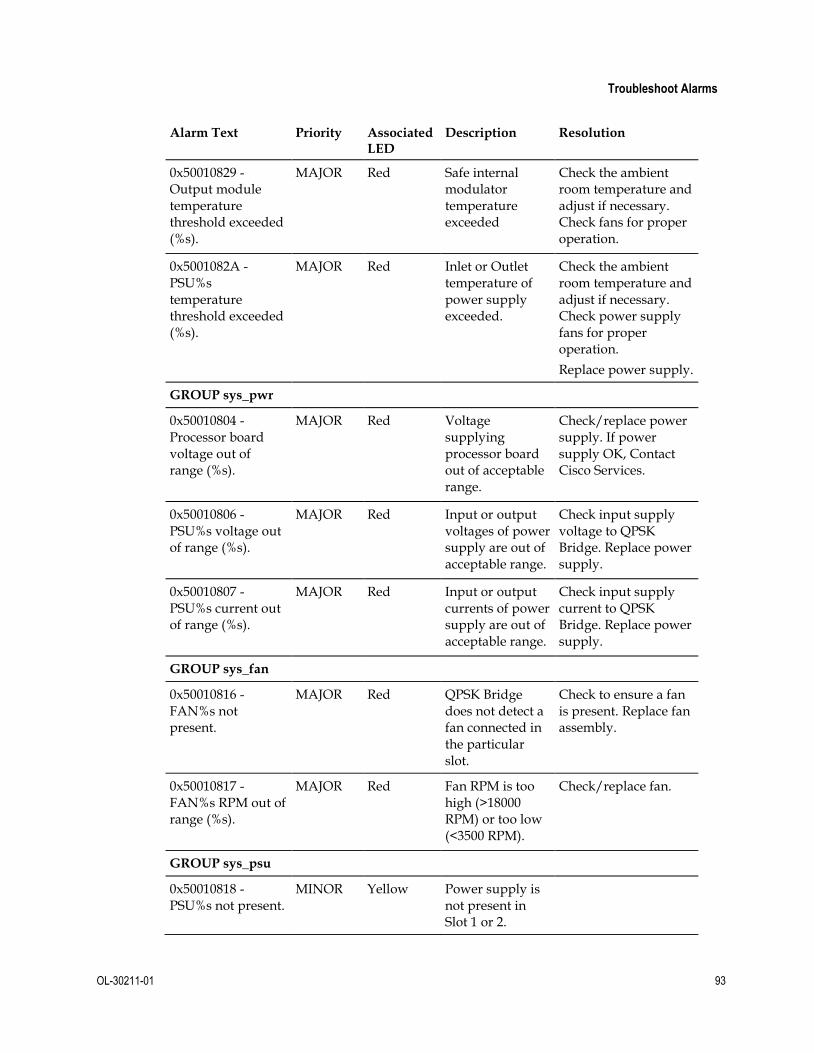
Troubleshoot Alarms
OL-30211-01 93
Alarm Text Priority Associated LED
Description Resolution
0x50010829 - Output module temperature threshold exceeded (%s).
MAJOR Red Safe internal modulator temperature exceeded
Check the ambient room temperature and adjust if necessary. Check fans for proper operation.
0x5001082A - PSU%s temperature threshold exceeded (%s).
MAJOR Red Inlet or Outlet temperature of power supply exceeded.
Check the ambient room temperature and adjust if necessary. Check power supply fans for proper operation.
Replace power supply.
GROUP sys_pwr
0x50010804 - Processor board voltage out of range (%s).
MAJOR Red Voltage supplying processor board out of acceptable range.
Check/replace power supply. If power supply OK, Contact Cisco Services.
0x50010806 - PSU%s voltage out of range (%s).
MAJOR Red Input or output voltages of power supply are out of acceptable range.
Check input supply voltage to QPSK Bridge. Replace power supply.
0x50010807 - PSU%s current out of range (%s).
MAJOR Red Input or output currents of power supply are out of acceptable range.
Check input supply current to QPSK Bridge. Replace power supply.
GROUP sys_fan
0x50010816 - FAN%s not present.
MAJOR Red QPSK Bridge does not detect a fan connected in the particular slot.
Check to ensure a fan is present. Replace fan assembly.
0x50010817 - FAN%s RPM out of range (%s).
MAJOR Red Fan RPM is too high (>18000 RPM) or too low (<3500 RPM).
Check/replace fan.
GROUP sys_psu
0x50010818 - PSU%s not present.
MINOR Yellow Power supply is not present in Slot 1 or 2.

Chapter 5 Troubleshooting the DAVIC QPSK Bridge
94 OL-30211-01
Alarm Text Priority Associated LED
Description Resolution
%s - PSU%s has failed.
MAJOR Red Power supply has failed and is not providing power.
Replace power supply. Ensure it is plugged into a power source.
GROUP sys_hw
0x50010809 - Failed FPGA DDR memory test.
MAJOR Red FPGA has a bad memory module.
Try to reboot the system. Contact Cisco Services.
0x5001080E - Failed component (%s).
MAJOR Red An important system component has failed.
Check/replace component if possible. Reboot system. Contact Cisco Services.
0x5001080F - Failed ethernet port (%s).
MAJOR Red Ethernet port is not working. Not receiving or sending data.
0x50010601 - Receive errors on ethernet port (%s).
MINOR Yellow Packets were not received correctly.
Check source and cables.
0x50010602 - Transmit errors on ethernet port (%s).
MINOR Yellow Packets were not transmitted correctly.
Check your cable. Reseat/replace cable.
0x50010810 - Front Panel failure (%s).
MINOR Yellow Front panel is no longer working, or communication with the front panel has been lost.
Reboot system. Contact Cisco Services.
GROUP dhcp
0x5001010C - Pending BOOTP lease request.
STATUS None QPSK Bridge is waiting for a BOOTP lease from BOOTP server.
0x50010805 - BOOTP lease successfully acquired.
STATUS None QPSK Bridge has successfully acquired a BOOTP lease.

Troubleshoot Alarms
OL-30211-01 95
Alarm Text Priority Associated LED
Description Resolution
0x50010107 - Failed to acquire a BOOTP lease.
MAJOR Red QPSK Bridge did not acquire a BOOTP lease and does not have an IP address.
Ensure that the QPSK Bridge is properly configured on the BootP server.
Check the Ethernet cable to ensure a physical connection exists.
0x50010108 - Failed to open configuration file (%s).
MAJOR Red QPSK Bridge could not open the configuration file downloaded from the DNCS.
Ensure that the configuration file is in the correct format - .xml.
0x50010109 - Failed to read configuration file (%s).
MAJOR Red QPSK Bridge could not read the downloaded configuration file from the DNCS.
Verify that the configuration file on the DNCS is in the correct format and contains all required information.
GROUP stb_ctl
0x50010208 - VCI usage exceeds threshold (%s).
STATUS None VCI usage has exceeded the threshold you set.
0x50010207 - Invalid DAVIC message type.
STATUS None The QPSK Bridge received an invalid DAVIC message.
0x50010200 - MAC configuration failed.
MAJOR Red MAC configuration failed to load properly.
Reboot
0x50010202 - DHCT not responding (%s).
STATUS None DHCT with MAC address %s did not send a response to the QPSK Bridge's STATUS message.

Chapter 5 Troubleshooting the DAVIC QPSK Bridge
96 OL-30211-01
Alarm Text Priority Associated LED
Description Resolution
0x5001081B - Total DHCTs exceeds limit (%s).
MINOR Yellow The total number of DHCTs trying to sign onto the QPSK Bridge has exceeded the maximum set on DNCS.
Reduce the number of DHCTs provisioned on the QPSK Bridge.
0x5001020B - DHCT sign-on ranging failure (%s).
STATUS None DHCT with MAC address %s did not sign on because it has failed.
0x5001020C - DHCT connected ranging failure (%s).
STATUS None DHCT with MAC address %s was in the idle state, but failed to stay in PETE and failed it's connection.
GROUP stb_ctl_demod
0x5001081C - DHCTs exceeds limit on demod %s.
MINOR
YELLOW
Too many DHCTs are trying to sign on to demod 1-8. Limit is user configurable.
Reduce the number of DHCTs signing on to demod (1-8).
GROUP scheduler
0x50010204 - Temporarily lost slot boundary generation synchronization.
STATUS None The system has lost frame generation synchronization.
0x5001020A - Dynamic Ranging reached max (ranging every frame).
STATUS None The system has enough contention on the sign-on ranging slot that it has reached the point that every frame has a sign-on opportunity.

Troubleshoot Alarms
OL-30211-01 97
Alarm Text Priority Associated LED
Description Resolution
0x5001082F - Scheduler discarded one or more schedules (%s).
STATUS None The system has discarded a DHCT schedule due to processing mismatch (high CPU load).
0x50010831 - Scheduler encountered one or more full queues (%s).
STATUS None The system scheduler buffer is full and has overflown.
GROUP inmapd
0x5001081D - Issuing Multicast Join on %s.
STATUS None The system has issued an IGMP join request.
0x5001081E - Issuing Multicast Leave on %s.
STATUS None The system has issued an IGMP leave request.
GROUP mod_mgr_task
0x50010000 - Reboot complete.
STATUS None System reboot has completed.
0x50010001 - Modulator frequency changed %s.
STATUS None Modulator RF Output frequency has changed from x Hz to y Hz.
0x50010002 - Modulator RF level changed %s.
STATUS None Modulator RF Output level has changed from x dB to y dB.
0x50010003 - Front panel display locked.
STATUS None Front panel LCD and buttons are locked and cannot be used.
0x50010004 - Modulator CW mode on.
MINOR Yellow CW Mode is enabled. Not used in normal operation.
0x50010005 - Modulator FP RF muted.
MINOR Yellow The RF Output on the modulator is disabled.
Enable Modulator RF Output.
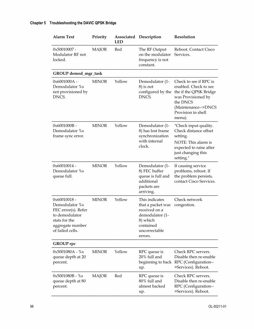
Chapter 5 Troubleshooting the DAVIC QPSK Bridge
98 OL-30211-01
Alarm Text Priority Associated LED
Description Resolution
0x50010007 - Modulator RF not locked.
MAJOR Red The RF Output on the modulator frequency is not constant.
Reboot. Contact Cisco Services.
GROUP demod_mgr_task
0x6001000A - Demodulator %s not provisioned by DNCS.
MINOR Yellow Demodulator (1-8) is not configured by the DNCS.
Check to see if RPC is enabled. Check to see the if the QPSK Bridge was Provisioned by the DNCS (Maintenance-->DNCS Provision in shell menu).
0x6001000B - Demodulator %s frame sync error.
MINOR Yellow Demodulator (1-8) has lost frame synchronization with internal clock.
"Check input quality. Check distance offset setting.
NOTE: This alarm is expected to raise after just changing this setting."
0x60010014 - Demodulator %s queue full.
MINOR Yellow Demodulator (1-8) FEC buffer queue is full and additional packets are arriving.
If causing service problems, reboot. If the problem persists, contact Cisco Services.
0x60010018 - Demodulator %s FEC error(s). Refer to demodulator stats for the aggregate number of failed cells.
MINOR Yellow This indicates that a packet was received on a demodulator (1-8) which contained uncorrectable errors.
Check network congestion.
GROUP rpc
0x5001080A - %s queue depth at 20 percent.
MINOR Yellow RPC queue is 20% full and beginning to back up.
Check RPC servers. Disable then re-enable RPC (Configuration-->Services). Reboot.
0x5001080B - %s queue depth at 80 percent.
MAJOR Red RPC queue is 80% full and almost backed up.
Check RPC servers. Disable then re-enable RPC (Configuration-->Services). Reboot.

Troubleshoot Alarms
OL-30211-01 99
Alarm Text Priority Associated LED
Description Resolution
0x5001080C - %s queue depth at 99 percent.
MAJOR Red RPC queue is full.
Check RPC servers. Disable then re-enable RPC (Configuration-->Services). Reboot.
0x50010101 - QPSK_MGR not connected (%s).
MINOR Yellow QPSK Bridge cannot connect to the QPSK_MGR.
Check the IP address of the QPSK_MGR (Configuration-->DNCS in the Shell menu). Check network path to RPC server. Check to ensure the RPC service has not gone down.
0x50010102 - HCT_MGR not connected (%s).
MINOR Yellow QPSK Bridge cannot connect to the HCT_MGR.
Check the IP address of the HCT_MGR (Configuration-->DNCS in the Shell menu).Check network path to RPC server. Check to ensure the RPC service has not gone down.
0x50010103 - ALM_MGR not connected (%s).
MINOR Yellow QPSK Bridge cannot connect to the ALM_MGR.
Check the IP address of the ALM_MGR (Configuration-->DNCS in the Shell menu). Check network path to RPC server. Check to ensure the RPC service has not gone down.
0x50010811 - SMG_MGR not connected (%s).
MINOR Yellow QPSK Bridge cannot connect to the SMG_MGR.
Check the IP address of the SMG_MGR (Configuration-->DNCS in the Shell menu). Check network path to RPC server. Check to ensure the RPC service has not gone down.

Chapter 5 Troubleshooting the DAVIC QPSK Bridge
100 OL-30211-01
Alarm Text Priority Associated LED
Description Resolution
0x50010100 - Did not receive provisioning from DNCS.
MINOR Yellow QPSK Bridge did not download a configuration file from the DNCS as expected.
Check to ensure that the DNCS is configured to provide a configuration file to the QPSK Bridge. Ensure that system is in Boot Mode 2.
Group data_path
0x50010504 - Upstream Buffer Overflow (%s).
MINOR Yellow Internal receive buffer has filled on Demod 1-8.
May resolve itself with time. Check DHCTs.
0x50010820 - Upstream Buffer Overflow rate exceeded threshold.
STATUS None Upstream buffer has exceeded 1.544 Mbps/demod.
0x50010821 - Downstream Buffer Overflow rate exceeded threshold.
STATUS None Internal transmit buffer has exceeded 1.544 Mbps/demod.
0x50010822 - OOB bandwidth Overflow exceeded threshold level.
STATUS None OOB bandwidth threshold has been exceeded and will raise a SNMP trap. OOB modulator is sending too much traffic to the DHCT population. Bandwidth threshold is configurable via SNMP.
0x5001050B - AAL5 CRC Error (%s).
MINOR Yellow Reconstructed packets did not pass the CRC check.
Check RF network setup (upstream RF settings and levels). This can occur with a lot of sign on activity. Wait until sign on activity decreases and check if alarm is still raised.
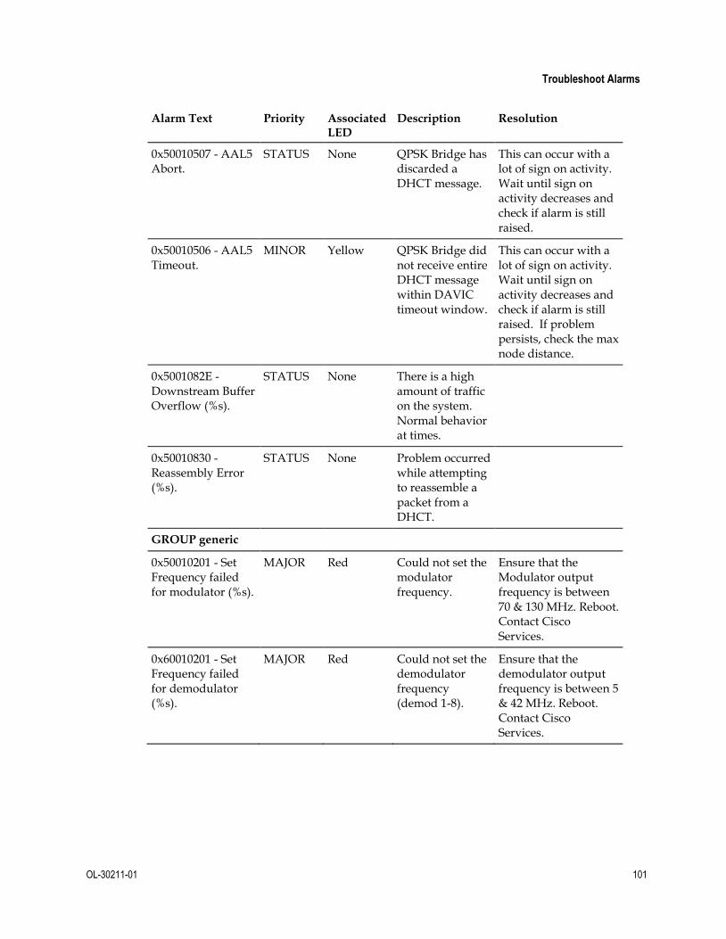
Troubleshoot Alarms
OL-30211-01 101
Alarm Text Priority Associated LED
Description Resolution
0x50010507 - AAL5 Abort.
STATUS None QPSK Bridge has discarded a DHCT message.
This can occur with a lot of sign on activity. Wait until sign on activity decreases and check if alarm is still raised.
0x50010506 - AAL5 Timeout.
MINOR Yellow QPSK Bridge did not receive entire DHCT message within DAVIC timeout window.
This can occur with a lot of sign on activity. Wait until sign on activity decreases and check if alarm is still raised. If problem persists, check the max node distance.
0x5001082E - Downstream Buffer Overflow (%s).
STATUS None There is a high amount of traffic on the system. Normal behavior at times.
0x50010830 - Reassembly Error (%s).
STATUS None Problem occurred while attempting to reassemble a packet from a DHCT.
GROUP generic
0x50010201 - Set Frequency failed for modulator (%s).
MAJOR Red Could not set the modulator frequency.
Ensure that the Modulator output frequency is between 70 & 130 MHz. Reboot. Contact Cisco Services.
0x60010201 - Set Frequency failed for demodulator (%s).
MAJOR Red Could not set the demodulator frequency (demod 1-8).
Ensure that the demodulator output frequency is between 5 & 42 MHz. Reboot. Contact Cisco Services.

Chapter 5 Troubleshooting the DAVIC QPSK Bridge
102 OL-30211-01
Alarm Text Priority Associated LED
Description Resolution
0x50010823 - Primary Service Frequency is set to a value that is not serviced by any demodulators on this chassis.
MINOR Yellow The Primary Service Frequency from the DNCS for the DHCTs is set to a frequency for which no demodulators are configured.
Ensure that the Primary Service Frequency set in the DNCS and the frequency of the demodulators on the QPSK Bridge, match.
0x50010824 - Backup Service Frequency is set to a value that is not serviced by any demodulators on this chassis.
MINOR Yellow The Backup Service Frequency from the DNCS for the DHCTs is set to a frequency for which no demodulators are configured.
Ensure that the Backup Service Frequency set in the DNCS and the frequency of the demodulators on the QPSK Bridge, match.

OL-30211-01 103
If You Have Questions
If you have technical questions, call Cisco Services for assistance. Follow the menu options to speak with a service engineer.
Access your company's extranet site to view or order additional technical publications. For accessing instructions, contact the representative who handles your account. Check your extranet site often as the information is updated frequently.
6 Chapter 6 Customer Information


OL-30211-01 105
A Appx auto letter Appendix A QPSK Bridge Configuration File
Introduction
The QPSK Bridge configuration file, with explanation, found in this appendix, can be copied and pasted for use.
Note: The configuration file must be delivered to the QPSK Bridge as an XML file.
In This Appendix
The QPSK Configuration File ............................................................ 106

Appendix A QPSK Bridge Configuration File
106 OL-30211-01
The QPSK Configuration File <?xml version="1.0" encoding="UTF-8"?>
<ifacade_config>
<!--Do not modify these settings. -->
<head>
<Version>1</Version>
<Product>D9485</Product>
<Checksum>0x12345</Checksum>
</head>
<config set="boot">
<!--Radius server information. Mandatory: No. -->
<RADIUS view="earlyboot">
<Server></Server> <!--The IP address of RADIUS server-->
<Secret></Secret> <!--The password that the D9485 uses to authenticate with the RADIUS server-->
<Timeout__s_></Timeout__s_> <!--The timeout period before the D9485 will no longer attempt to obtain a password from the RADIUS server. -->
<Enabled>No</Enabled> <!--Set the status of the RADIUS server. When set to “No”, the D9485 will not attempt to authenticate with the RADIUS server. -->
</RADIUS>
<!--Leaving these fields blank or entering ‘Disabled’ will turn these connections off. Mandatory: Yes. -->
<DNCS_Connection_Parameters view="earlyboot">
<HCT_RPC_Server>10.253.0.1</HCT_RPC_Server> <!--This is the IPv4 address for the RPC HCT Server. -->
<MGR_RPC_Server>10.253.0.1</MGR_RPC_Server> <!--This is the IPv4 address for the RPC MGR Server. -->
<ALARM_RPC_Server>10.253.0.1</ALARM_RPC_Server> <!--This is the IPv4 address for the RPC ALARM Server. -->

The QPSK Configuration File
OL-30211-01 107
<STATS_RPC_Server>10.253.0.1</STATS_RPC_Server> <!--This is the IPv4 address for the RPC STATS Server. -->
</DNCS_Connection_Parameters>
<!--Chassis identifiers used to set custom parameters for identifying the chassis. Mandatory: No. -->
<Chassis view="earlyboot">
<Name>GALIANO_05R2</Name> <!--User configurable chassis name. This can be set to any string. -->
<System_Model>D9485</System_Model> <!--User configurable system model number. -->
<Boot_Mode>Multiple BOOTP/TFTP (mode 2)</Boot_Mode> <!--Boot Mode for the system. Can be set to: NVRAM (mode 0); Singe BOOTP/TFTP (mode 1); Multiple BOOTP/TFTP (mode 2). Default is ‘Multiple BOOTP/TFTP (mode 2)’. For more information on Boot modes, see Chassis -->
</Chassis>
<!--Locks the front panel button functionality. When locked, the front panel buttons will not perform any function. Mandatory: No-->
<Front_Panel_Lock view="earlyboot">
<Locked>No</Locked> <!--Can be Yes or No-->
</Front_Panel_Lock>
<!--Craft Port Settings – for more information see ‘Direct Connectivity’. Manditory: No. -->
<CRAFT_Port_Settings view="earlyboot">
<Baud_Rate>19200</Baud_Rate>
<Data_Bits>8</Data_Bits>
<Stop_Bits>1</Stop_Bits>
<Parity>None</Parity>
</CRAFT_Port_Settings>
<!--User Configurable Technical Support Information. This information is displayed on the UI. Mandatory: No.-->
<Technical_Support view="earlyboot">

Appendix A QPSK Bridge Configuration File
108 OL-30211-01
<Email>[email protected]</Email>
<Telephone>(555)555-5555</Telephone>
<Web>www.cisco.com</Web>
</Technical_Support>
<!--Identifies the Remote Syslog servers for system logs. Syslog server addresses can be IPv4 or server names. Mandatory: No.-->
<Remote_Targets view="earlyboot">
<Target_Host_Name>localhost</Target_Host_Name>
</Remote_Targets>
<Remote_Targets view="earlyboot">
<Target_Host_Name>127.0.0.1</Target_Host_Name>
</Remote_Targets>
<!--Fiber Distance Setting. User settable maximum node distance setting for the DHCTs connected to the D9485. Mandatory: No-->
<Modulator_Fiber_Distance_Setting view="earlyboot">
<Max_Node_Distance>0 km</Max_Node_Distance> <!-- Range: 0km–248km, in 31 km increments. For more information on correctly setting the modulator fiber distance setting, see “QPSK Delay Mode Technical Bulletin” application notes.-->
</Modulator_Fiber_Distance_Setting>
<!--Modulator settings of the Low RF Output port. See section ‘3. Modulator’ for more information. Mandatory: Yes. -->
<Modulator view="running">
<RF_Output_Port>Low</RF_Output_Port> <!--Always ‘Low’-->
<Frequency>83000000 Hz</Frequency> <!--Frequency (70 – 130 MHz) -->
<Power_Level>60 dBmV</Power_Level> <!--Power Level (50 – 60 dBmV) -->
<CW_Mode>Disabled</CW_Mode> <!--Continuous Wave Mode. When enabled, the output will only be a carrier. -->
<DNCS_Provisioned>Enabled</DNCS_Provisioned> <!--DNCS will configure the modulator port when enabled. When disabled, the modulator must be a configured manually or via this configuration file. -->

The QPSK Configuration File
OL-30211-01 109
<RF_Output>Unmuted</RF_Output> <!--Activates\Deactivates the RF Output port. When ‘Muted’, there is no output present on the port. Set to ‘Unmuted’ for normal operation. -->
</Modulator>
<!-- The entries below are for configuring each of the 8 QPSK demodulators. See section ‘7. Demodulators’ for more information on these settings. Each demodulator must be configured individually. Mandatory: Yes. -->
<Demodulator view="running">
<Number>1</Number> <!--Demodulator identifier (1-8) -->
<DNCS_Name>NODE15A</DNCS_Name> <!--DHCT node name-->
<Frequency__Hz_>11000000</Frequency__Hz_> <!--Frequency (5 – 42 MHz) -->
<Attenuation>0 dB</Attenuation> <!--Attenuation (0, 8, 16, or 24 dB) -->
<DNCS_Provisioned>Enabled</DNCS_Provisioned> <!--Describes if the demodulator is provisioned by the DNCS. Enabled = Yes; Disabled = No. -->
<DNCS_Enabled>Enabled</DNCS_Enabled> <!--Functioning state of the demodulator. Enabled = On; Disabled = Off. -->
</Demodulator>
<Demodulator view="running">
<Number>2</Number>
<DNCS_Name>UNKNOWN</DNCS_Name>
<Frequency__Hz_>5000000</Frequency__Hz_>
<Attenuation>0 dB</Attenuation>
<DNCS_Provisioned>Disabled</DNCS_Provisioned>
<DNCS_Enabled>Disabled</DNCS_Enabled>
</Demodulator>
<Demodulator view="running">
<Number>3</Number>
<DNCS_Name>UNKNOWN</DNCS_Name>
<Frequency__Hz_>5000000</Frequency__Hz_>
<Attenuation>0 dB</Attenuation>
<DNCS_Provisioned>Disabled</DNCS_Provisioned>
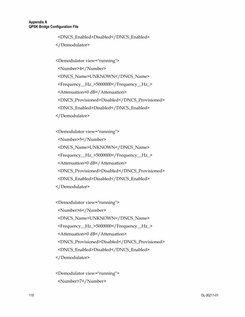
Appendix A QPSK Bridge Configuration File
110 OL-30211-01
<DNCS_Enabled>Disabled</DNCS_Enabled>
</Demodulator>
<Demodulator view="running">
<Number>4</Number>
<DNCS_Name>UNKNOWN</DNCS_Name>
<Frequency__Hz_>5000000</Frequency__Hz_>
<Attenuation>0 dB</Attenuation>
<DNCS_Provisioned>Disabled</DNCS_Provisioned>
<DNCS_Enabled>Disabled</DNCS_Enabled>
</Demodulator>
<Demodulator view="running">
<Number>5</Number>
<DNCS_Name>UNKNOWN</DNCS_Name>
<Frequency__Hz_>5000000</Frequency__Hz_>
<Attenuation>0 dB</Attenuation>
<DNCS_Provisioned>Disabled</DNCS_Provisioned>
<DNCS_Enabled>Disabled</DNCS_Enabled>
</Demodulator>
<Demodulator view="running">
<Number>6</Number>
<DNCS_Name>UNKNOWN</DNCS_Name>
<Frequency__Hz_>5000000</Frequency__Hz_>
<Attenuation>0 dB</Attenuation>
<DNCS_Provisioned>Disabled</DNCS_Provisioned>
<DNCS_Enabled>Disabled</DNCS_Enabled>
</Demodulator>
<Demodulator view="running">
<Number>7</Number>

The QPSK Configuration File
OL-30211-01 111
<DNCS_Name>UNKNOWN</DNCS_Name>
<Frequency__Hz_>5000000</Frequency__Hz_>
<Attenuation>0 dB</Attenuation>
<DNCS_Provisioned>Disabled</DNCS_Provisioned>
<DNCS_Enabled>Disabled</DNCS_Enabled>
</Demodulator>
<Demodulator view="running">
<Number>8</Number>
<DNCS_Name>UNKNOWN</DNCS_Name>
<Frequency__Hz_>5000000</Frequency__Hz_>
<Attenuation>0 dB</Attenuation>
<DNCS_Provisioned>Disabled</DNCS_Provisioned>
<DNCS_Enabled>Disabled</DNCS_Enabled>
</Demodulator>
<!-- The VPI is used to identify the virtual circuit used by the DNCS to identify a unique QPSK Bridge. Mandatory: No. -->
<VPI view="running">
<VPI>29</VPI> <!-- Can be any number between 0 and 255. -->
</VPI>
<Service_Frequencies view="running">
<Service_Channel_Frequency>11000000 Hz</Service_Channel_Frequency> <!-- The Service Frequency is the upstream frequency (or RDC) at which the QPSK Bridge tells the DHCTs to transmit data. This is a frequency between 5 MHz and 42 MHz and should correspond to the frequency of the associated demodulator. Mandatory: Yes-->
<Backup_Service_Channel_Frequency>11000000 Hz</Backup_Service_Channel_Frequency> <!-- The backup frequency is used as an alternate service frequency should a change in network variables require a frequency change. Typically, this value is the same as the Service Channel Frequency. Mandatory: Yes. -->
</Service_Frequencies>

Appendix A QPSK Bridge Configuration File
112 OL-30211-01
<!--Allows the user to set the upstream (RDC) power levels for the DHCTs. These are typically configured through the DNCS. Mandatory: No. -->
<Power_Levels view="running">
<Acceptable_minimum>-9 dBmV</Acceptable_minimum> <!--The minimum acceptable power level of a DHCT as measured by the QPSK Bridge demodulator. -->
<Acceptable_maximum>-1 dBmV</Acceptable_maximum> <!--The maximum acceptable power level of a DHCT as measured by the QPSK Bridge demodulator. -->
<Target_minimum>-8 dBmV</Target_minimum> <!--The ideal minimum acceptable power level of a DHCT as measured by the QPSK Bridge demodulator. -->
<Target_maximum>-2 dBmV</Target_maximum> <!--The ideal maximum acceptable power level of a DHCT as measured by the QPSK Bridge demodulator. -->
<DHCT_minimum>0 dBmV</DHCT_minimum> <!--The minimum transmission power levels as measured at the upstream port of a DHCT. Levels depend on model of DHCT. -->
<DHCT_maximum>50 dBmV</DHCT_maximum> <!--The maximum transmission power levels as measured at the upstream port of a DHCT. Levels depend on model of DHCT. -->
</Power_Levels>
<!--Data Routing describes the different data types flowing through the QPSK Bridge. It is recommended that changes to these data flows be made through the DNCS. Each rule must be set individually. See ‘2. Networking’ for more information. Mandatory: Yes. -->
<Data_Routing view="running">
<Rule>1</Rule> <!--Designator (1-8) -->
<Active>Enabled</Active> <!--Enabled/Disabled-->
<Name>CA</Name> <!--Data name-->
<Type>CA</Type> <!--Data type-->
<Dest_IP>10.15.64.1</Dest_IP> <!--Destination IP address for data type-->
<VPI>0</VPI> <!--Virtual Path Identifier (0-255) -->
<VCI>4000</VCI> <!--Virtual Channel Identifier-->
</Data_Routing>

The QPSK Configuration File
OL-30211-01 113
<Data_Routing view="running">
<Rule>2</Rule>
<Active>Enabled</Active>
<Name>SAR</Name>
<Type>SAR</Type>
<Dest_IP>10.15.64.2</Dest_IP>
<VPI>0</VPI>
<VCI>0</VCI>
</Data_Routing>
<Data_Routing view="running">
<Rule>3</Rule>
<Active>Enabled</Active>
<Name>PASSTHRU</Name>
<Type>PASSTHRU</Type>
<Dest_IP>10.15.64.3</Dest_IP>
<VPI>0</VPI>
<VCI>4001</VCI>
</Data_Routing>
<Data_Routing view="running">
<Rule>4</Rule>
<Active>Enabled</Active>
<Name>SI</Name>
<Type>SIBASE</Type>
<Dest_IP>10.15.64.4</Dest_IP>
<VPI>0</VPI>
<VCI>4002</VCI>
</Data_Routing>
<Data_Routing view="running">
<Rule>5</Rule>
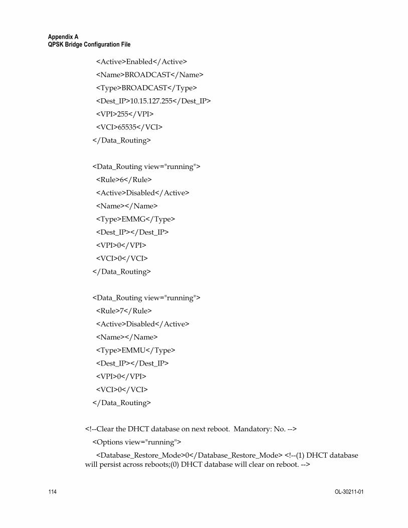
Appendix A QPSK Bridge Configuration File
114 OL-30211-01
<Active>Enabled</Active>
<Name>BROADCAST</Name>
<Type>BROADCAST</Type>
<Dest_IP>10.15.127.255</Dest_IP>
<VPI>255</VPI>
<VCI>65535</VCI>
</Data_Routing>
<Data_Routing view="running">
<Rule>6</Rule>
<Active>Disabled</Active>
<Name></Name>
<Type>EMMG</Type>
<Dest_IP></Dest_IP>
<VPI>0</VPI>
<VCI>0</VCI>
</Data_Routing>
<Data_Routing view="running">
<Rule>7</Rule>
<Active>Disabled</Active>
<Name></Name>
<Type>EMMU</Type>
<Dest_IP></Dest_IP>
<VPI>0</VPI>
<VCI>0</VCI>
</Data_Routing>
<!--Clear the DHCT database on next reboot. Mandatory: No. -->
<Options view="running">
<Database_Restore_Mode>0</Database_Restore_Mode> <!--(1) DHCT database will persist across reboots;(0) DHCT database will clear on reboot. -->

The QPSK Configuration File
OL-30211-01 115
</Options>
<!--This is the process of adjusting the transmitted power and timing delay for DAVIC messages from a DHCT for optimal performance. Mandatory: Yes. -->
<DAVIC_Ranging view="lateboot">
<State>Enabled</State> <!--Cab be Enabled or Disabled
</DAVIC_Ranging>
<!--Set the rate at which DAVIC broadcast messages are sent to DHCTs. Mandatory: Yes. -->
<DAVIC_Broadcast_Messages view="lateboot">
<Broadcast_Rate>1 second(s)</Broadcast_Rate> <!--Between 1-15 seconds per broadcast message. -->
</DAVIC_Broadcast_Messages>
<!--Enable/Disable Network Services. Used to enable non-essential networking services. All non-essential services default to disabled if not explicitly set to enabled. Mandatory: Yes-->
<Network_Services view="lateboot">
<SSH>Enabled</SSH> <!-- Enabled/Disabled
<HTTP>Enabled</HTTP> <!-- Enabled/Disabled
<SNMP>Enabled</SNMP> <!-- Enabled/Disabled
</Network_Services>
<!--SNMP Communities – see SNMP on page 45 for more information. You may define up to 5 SNMP Communities. Mandatory: No-->
<SNMP_Communities view="lateboot">
<Community_Name>test</Community_Name> <!--User settable name of the SNMP Community. Each Community Name must be a unique string. -->
<Access_Mode>ReadOnly</Access_Mode> <!--Configurable permissions for this community. Can be set to ‘ReadOnly’ or ‘ReadWrite’. -->
</SNMP_Communities>
<SNMP_Communities view="lateboot">
<Community_Name>test2</Community_Name>

Appendix A QPSK Bridge Configuration File
116 OL-30211-01
<Access_Mode>ReadOnly</Access_Mode>
</SNMP_Communities>
<!--SNMP Trap Recievers - see SNMP on page 45 for more information. You may define up to 5 SNMP Trap receivers. Mandatory: No. -->
<Trap_Receivers view="lateboot">
<IP_Address>127.0.0.1</IP_Address> <!--IPv4 address of the SNMP Trap receiver. -->
<Port_Number>1234</Port_Number> <!--Port to use for sending the SNMP traps to. [1 .. 65535]. Typically 162. -->
<Notification_Version>v2</Notification_Version> <!--SNMP trap receiver version: "v2".-->
<Notification_Type>Trap</Notification_Type> <!--Sets the receiver type: 'Trap' one way, no acknowledgement 'Inform' acknowledgment from receiver 'Disabled' receiver is disabled. Traps will not be sent. -->
</Trap_Receivers>
<Trap_Receivers view="lateboot">
<IP_Address>127.0.0.2</IP_Address>
<Port_Number>1235</Port_Number>
<Notification_Version>v2</Notification_Version>
<Notification_Type>Trap</Notification_Type>
</Trap_Receivers>
<!--SNMP Trap Identifiers used to identify a D9485 from other trap devices in a network. These fields populate saltUserName and saltDeviceInstance in the SNMP trap. These cannot be set through the system Shell menu. Mandatory: No. -->
<SNMP_Trap_Values view="lateboot">
<SALTUSERNAME>System</SALTUSERNAME> <!--String of length 0 – 255 bytes.
<SALTDEVICENAME>QPSK</SALTDEVICENAME> <!--String of length 0 – 255 bytes.
</SNMP_Trap_Values>

The QPSK Configuration File
OL-30211-01 117
<!--System Upgrade. Automatically start and upgrade on boot. For more information, see the section on Upgrading the QPSK Bridge. Mandatory: No. -->
<System_Upgrade view="lateboot">
<TFTP_Server_or_HTTP_Address>http://192.168.2.3</TFTP_Server_or_HTTP_Address> <!--TFTP or HTTP address of Upgrade Server. -->
<Upgrade_File>1.2.16.bin.signed</Upgrade_File> <!--TFTP: The full path and filename of the upgrade file as located on the TFTP Server identified above. For example, if the file is located on server 192.168.2.3 in /tftpboot/QPSK_files/D9485_REL_4P_1_2_16-G.bin.signed use TFTP_Server_or_HTTP_Address: 192.168.2.3. Upgrade_File: QPSK_files/D9485_REL_4P_1_2_16-G.bin.signed, assuming /tftpboot is the root directly for the server. The filename to use is located at the HTTP_Address above. If the file is accessible at http:<!--192.168.2.3/QPSK_files/D9485_REL_4P_1_2_16-G.bin.signed use TFTP_Server_or_HTTP_Address: http:<!--192.168.2.3/QPSK_files Upgrade_File: D9485_REL_4P_1_2_16-G.bin.signed-->
</System_Upgrade>
</config>
</ifacade_config>

Americas Headquarters Cisco Systems, Inc. 170 West Tasman Drive San Jose, CA 95134-1706 USA
http://www.cisco.com Tel: 408 526-4000
800 553-6387 Fax: 408 527-0883
This document includes various trademarks of Cisco Systems, Inc. Please see the Notices section of this document for a list of the Cisco Systems, Inc. trademarks used in this document. Product and service availability are subject to change without notice.
© 2014 Cisco and/or its affiliates. All rights reserved. April 2014
Part Number OL-30211-01