d75 manw_20121207.pdf
TRANSCRIPT

8/21/2019 D75 MANw_20121207.pdf
http://slidepdf.com/reader/full/d75-manw20121207pdf 1/128

8/21/2019 D75 MANw_20121207.pdf
http://slidepdf.com/reader/full/d75-manw20121207pdf 2/128
R-16 / Dec 1997
D-75 Digital Audio Console Technical Manual - 1st EditionD-75 Digital Audio Console Technical Manual - 1st EditionD-75 Digital Audio Console Technical Manual - 1st EditionD-75 Digital Audio Console Technical Manual - 1st EditionD-75 Digital Audio Console Technical Manual - 1st Edition
©2004 Audioarts® Engineering*
AUDIOARTS ENGINEERING
600 Industrial Drive
New Bern, North Carolina 28562
252-638-7000
*a division of Wheatstone Corporation
D-75 / Sep 2004

8/21/2019 D75 MANw_20121207.pdf
http://slidepdf.com/reader/full/d75-manw20121207pdf 3/128
AAAAATTENTIONTTENTIONTTENTIONTTENTIONTTENTION
RRRRREADEADEADEADEAD MMMMMEEEEE!!!!!D-75 / Ap 2008
Attention!
FFFFFederal Communications Commission (FCC) Complianceederal Communications Commission (FCC) Complianceederal Communications Commission (FCC) Complianceederal Communications Commission (FCC) Complianceederal Communications Commission (FCC) Compliance
Notice:Notice:Notice:Notice:Notice:
Radio FRadio FRadio FRadio FRadio Frequency Noticerequency Noticerequency Noticerequency Noticerequency Notice
NOTE:NOTE:NOTE:NOTE:NOTE: This equipment has been tested and found to comply with thelimits for a Class A digital device, pursuant to Part 15 of the FCC rules. Theselimits are designed to provide reasonable protection against harmful
interference when the equipment is operated in a commercial environment. This equipment generates, uses, and can radiate radio frequency energy and, if not installed and used in accordance with the instruction manual,may cause harmful interference to radio communications. Operation of thisequipment in a residential area is likely to cause harmful interference in which case the user will be required to correct the interference at his ownexpense.
! This is a Class A product. In a domestic environment, this This is a Class A product. In a domestic environment, this This is a Class A product. In a domestic environment, this This is a Class A product. In a domestic environment, this This is a Class A product. In a domestic environment, this
product may cause radio interference, in which case, theproduct may cause radio interference, in which case, theproduct may cause radio interference, in which case, theproduct may cause radio interference, in which case, theproduct may cause radio interference, in which case, theuser may be required to take appropriate measures.user may be required to take appropriate measures.user may be required to take appropriate measures.user may be required to take appropriate measures.user may be required to take appropriate measures.
This equipment must be installed and wired properly in order to assurecompliance with FCC regulations.
Caution!Caution!Caution!Caution!Caution! Any modifications not expressly approved in writing by Any modifications not expressly approved in writing by Any modifications not expressly approved in writing by Any modifications not expressly approved in writing by Any modifications not expressly approved in writing by Audioarts could void the user's authority to operate this equipment. Audioarts could void the user's authority to operate this equipment. Audioarts could void the user's authority to operate this equipment. Audioarts could void the user's authority to operate this equipment. Audioarts could void the user's authority to operate this equipment.

8/21/2019 D75 MANw_20121207.pdf
http://slidepdf.com/reader/full/d75-manw20121207pdf 4/128
AAAAATTENTIONTTENTIONTTENTIONTTENTIONTTENTION
RRRRREADEADEADEADEAD MMMMMEEEEE!!!!!D-75 / Sep 2004
Attention!
This console contains static sensitive devices:Normal precautions against static discharge should be observed when
handling individual modules. In particular, modules being packed for shippingfor return or repair must be packed in special static protection bags beforepackaging. Damage caused by static discharge may not be covered underwarranty.
Replacing Modules in a Powered-up Console:While in an emergency situation it is possible to remove and insert modules
on a powered-up console, Wheatstone does not recommend this procedure.Whenever possible it is best to power down the console first before removingor replacing modules.
However, if you find you must proceed with this operation, then be sure totake the following precaution:
When re-inserting a module, take care to replug it squarely into itsmainframe connector socket, so all edgecard fingers make contact simultaneously. In other words, the gold-plated bus connector fingers on the
bottom edge of the module's printed circuit board must be inserted squarely(i.e., perpendicular) to the mating socket on the bottom pan of the consolemainframe. The intent is to prevent a situation where one of the module'spower pins makes significant contact before the others. (Naturally, thissame precaution must be taken when using extenders.)
If the above instructions are followed the procedure should be routine; if theyare not, you could run the risk of damaging the console's logic chips.
Again, to avoid ANY possibility of this damage, whenever possible westrongly recommend powering down the consolebefore replacing any modules.
!

8/21/2019 D75 MANw_20121207.pdf
http://slidepdf.com/reader/full/d75-manw20121207pdf 5/128
RRRRREADEADEADEADEAD MMMMMEEEEE!!!!!D-75 / Sep 2004
IMPORTANT!D-75 A D-75 A D-75 A D-75 A D-75 A udio Levelsudio Levelsudio Levelsudio Levelsudio Levels
GeneralGeneralGeneralGeneralGeneral
All professional digital audio broadcast consoles manufactured by Wheatstoneare hybrid in nature. That is, they allow the user to connect both analog anddigital domain sources and provide both analog and digital outputs. While thisapproach allows for greater flexibility when interconnecting source anddestination equipment, the user must be aware of what levels to expect whenapplying, say, a digital input and measuring at an analog output.
Gain StructurGain StructurGain StructurGain StructurGain Structureeeee
Broadcast consoles by design have various electronic stages at which thesignal level may be amplified or attenuated. The primary stages are the A-Dconverter input, channel fader, DSP mixing and the bus output D-A converters.
The sum of these gain stages is commonly referred to as the console’s “gainstructure”. Wheatstone consoles are factory calibrated for 0dB or “unity gain”
when the input channel fader is set to nominal (-12dB).
The following is a stage by stage breakdown of a typical console’s gain stages:
Analog Input (A-D Converter) Analog Input (A-D Converter) Analog Input (A-D Converter) Analog Input (A-D Converter) Analog Input (A-D Converter)
• trim pots located on the ADC input circuit cards are trimmed so that a +4dBU input signal will yield a -20dBFS digital output with the channel fader at nominal. Trim pot gain range at this stage allows for interfacing unbalancedequipment. Mic level ADC circuit cards have trim pots for matching variousmicrophone source levels to the console’s operating level.
DSP GainDSP GainDSP GainDSP GainDSP Gain
• set in firmware for unity gain, digital attenuation may be applied on a channel by channel basis via a dipswitch setting.
Analog Bus Output Gain (D-A Converter) Analog Bus Output Gain (D-A Converter) Analog Bus Output Gain (D-A Converter) Analog Bus Output Gain (D-A Converter) Analog Bus Output Gain (D-A Converter)
• trim pots located on the corresponding analog output DAC circuit card arefactory trimmed so that a -20dBFS digital input signal will yield a +4dBuanalog output with the channel fader at nominal. These may be adjusted over a range of -26 to -10dBFS = +4dBu.

8/21/2019 D75 MANw_20121207.pdf
http://slidepdf.com/reader/full/d75-manw20121207pdf 6/128
RRRRREADEADEADEADEAD MMMMMEEEEE!!!!!D-75 / Sep 2004
A A A A A udio Referudio Referudio Referudio Referudio Reference Levelsence Levelsence Levelsence Levelsence Levels
All consoles are fully factory calibrated and will comply with the followingreference level:
-20dBFS digital = +4dBu analog = 0VU Note: 0dBu = .775v rms
+4dBu = 1.23v rms
These settings will provide a headroom of 20dB over the nominal input signal of +4dBu analog, or -20dBFS digital. Should your facility require a different
A-D - D-A reference level please consult the factory for calibration details and/or alternate solutions.
Note that due to the lack of level standards in the digital domain, headroomavailable for digital sources will be entirely dependant on the source. In fact, CD'sare frequently made with less than 1dB of digital headroom, and any boosting of digital CD levels in the console by moving the fader up above the nominal canresult in overload distortion for that channel. For this reason, a dipswitch allowsfor digital attenuation on a fader by fader basis; digital sources can be conveniently attenuated this way to guard against digital overload caused by not enoughheadroom on the digital source. Since the D-75 console meters are true digitalreading meters, they will always show the console's digital levels, and whether there are any "overs" in the signal. By pressing a channel's "CUE" button, theswitched meters will show the digital level of that channel's source, as modified
by the dipswitch setting. By using the program and watching these meters, theamount of attenuation can be adjusted to meet your headroom requirements.
T T T T Typical Input Levelsypical Input Levelsypical Input Levelsypical Input Levelsypical Input Levels
Mic Inputs Nominal = -50dBm, 150Ω Maximum = -26dBm
Analog Inputs Nominal = +4dBu Maximum = +24dBu
Digital Inputs Nominal = -20dBFS Maximum = 0dBFS
IIIIIMPORTANTMPORTANTMPORTANTMPORTANTMPORTANT

8/21/2019 D75 MANw_20121207.pdf
http://slidepdf.com/reader/full/d75-manw20121207pdf 7/128
page Contents – 1D-75 / Sep 2004
C O N T E N T S
D-75 Technical Manual
Table of Contents
Chapter 1 – Installation and Power
Unpacking the Console ............................................................. 1-2
Countertop Mounting ................................................................. 1-2
System Ground .......................................................................... 1-3
Power Supply ............................................................................. 1-5
SPS Cable Pinout ................................................................................................... 1-5
Energizing ............................................................................................................... 1-6
Audio and Control Wiring .......................................................... 1-6
Connection Procedures .......................................................................................... 1-6
Digital Audio Connections ...................................................................................... 1-6
Unbalanced Connections (analog audio) ............................................................... 1-7
Modules Layout .......................................................................... 1-7
Input Daughter Cards Installation .......................................... 1-7a
Hand Crimp Tool Wiring Insrtuctions ...................................... 1-8
D-75-26 Modules Layout Drawing........................................... 1-10
D-75-18 Modules Layout Drawing........................................... 1-11
Chapter 2 - Quad Mic Preamp (QMP-4)
Overview ..................................................................................... 2-2
Internal Programming Options ................................................. 2-3
Phantom Power ...................................................................................................... 2-3
Hook-ups..................................................................................... 2-3
Audio Input Connections ........................................................................................ 2-3
Audio Output Connections...................................................................................... 2-4
Power Connections................................................................................................. 2-5
Plug Terminal Pinout Drawing .................................................. 2-6
Installing the Optional Second QMP-4 Mic Preamp ................ 2-7
D-75 / Nov 2005

8/21/2019 D75 MANw_20121207.pdf
http://slidepdf.com/reader/full/d75-manw20121207pdf 8/128
page Contents – 2D-75 / Sep 2004
C O N T E N T S
Chapter 3 - Stereo Line Input (IN-75)
Module Overview...........................................................................3-2
Internal Programming Options ....................................................3-3
Mutes ........................................................................................................................ 3-3Tallies........................................................................................................................ 3-3
Timer Restart ............................................................................................................ 3-3
Talkback.................................................................................................................... 3-3
Attenuation ................................................................................................................ 3-4
EFS - European Fader Start ..................................................................................... 3-4
Hook-ups........................................................................................3-4
Analog Audio Connections ....................................................................................... 3-4
Digital Audio Connections ........................................................................................ 3-5
Control Connections ................................................................................................. 3-5
Remote ON & OFF .............................................................................................. 3-5
Cough .................................................................................................................. 3-5
External START & STOP .................................................................................... 3-6 Ready................................................................................................................... 3-6
Talkback to Control Room ................................................................................... 3-6
On Tally ............................................................................................................... 3-6
Tally B .................................................................................................................. 3-6
DB Connector Pinout Drawings
Analog Inputs - ADC-75 ............................................................................................ 3-7
Digital Inputs - SRC-75 ............................................................................................. 3-8
Stereo Line Input Signal Flow ......................................................3-9
Chapter 4 - Output Module (OM-75)
Module Overview...........................................................................4-2
Internal Programming Options ....................................................4-3
Sampling Frequency for Console Outputs .................................4-3
Hook-ups........................................................................................4-4
Left DB-25 “B” Connector — Digital Audio Outputs, External Analog Inputs .......... 4-4
Right DB-25 “A” Connector — Analog Audio Outputs ............................................. 4-4
DB Connector Pinout Drawing.....................................................4-6
Output Module Signal Flow..........................................................4-7
Chapter 5 - Control Room Module (CR-75)
Module Overview...........................................................................5-2
Internal Programming Options ....................................................5-3
Cue Interrupt ............................................................................................................. 5-3
CR/Cue Mute ............................................................................................................ 5-3
On-Air Tally Follows Program................................................................................... 5-3
Hook-ups........................................................................................5-4
Left DB-25 “B” Connector — Audio .......................................................................... 5-4
Right DB-25 “A” Connector — Audio and On-Air Tally ............................................ 5-4

8/21/2019 D75 MANw_20121207.pdf
http://slidepdf.com/reader/full/d75-manw20121207pdf 9/128
page Contents – 3D-75 / Sep 2004
C O N T E N T S
DB Connector Pinout Drawing.....................................................5-5
Control Room Module Signal Flow..............................................5-6
Chapter 6 - Studio Control Module (SC-75)
Module Overview...........................................................................6-2
Internal Programming Options ....................................................6-3
External Talkback Mute/Dim..................................................................................... 6-3
Studio Dim ................................................................................................................ 6-3
Studio Pre Mute ........................................................................................................ 6-3
Hook-ups........................................................................................6-4
Left DB-25 “B” Connector — Audio .......................................................................... 6-4
Right DB-25 “A” Connector — Audio and Tally 2..................................................... 6-4
DB Connector Pinout Drawing.....................................................6-5
Studio Control Module Signal Flow.............................................6-6
Chapter 7 - Superphone Module (SP-75) - optional
Module Overview...........................................................................7-2
Caller Set-Ups .......................................................................................................... 7-2
Automatic Features................................................................................................... 7-3
Inputs and Outputs ................................................................................................... 7-3
Internal Programming Options ....................................................7-3
Cue Pre/Post ............................................................................................................ 7-3
Mutes ........................................................................................................................ 7-3
Timer Restart ............................................................................................................ 7-4
Tallies........................................................................................................................ 7-4
Cue Dropout.............................................................................................................. 7-4
External Input ............................................................................................................ 7-4
Gain Trimpots ........................................................................................................... 7-4
Hook-ups........................................................................................7-5
Left DB-25 “B” Connector—Audio & Control ............................................................ 7-5
External START & STOP .................................................................................... 7-5
Right DB-25 “A” Connector—Audio .......................................................................... 7-6
DB Connector Pinout Drawing.....................................................7-7
Superphone Input Module Signal Flow .......................................7-8
Chapter 8 - Line Preselect (LS-75) - optionalModule Overview...........................................................................8-2
Internal Programming Options ....................................................8-2
Hook-ups........................................................................................8-3
Left DB-25 “B” Connector — Audio Inputs ............................................................... 8-3
Left DB-25 “B” Connector — Audio Outputs ............................................................ 8-3
Right DB-25 “A” Connector — Audio Inputs ............................................................. 8-3
DB Connector Pinout Drawing.....................................................8-5
Line Preselect Module Signal Flow .............................................8-6
D-75 / Jan 2008

8/21/2019 D75 MANw_20121207.pdf
http://slidepdf.com/reader/full/d75-manw20121207pdf 10/128
page Contents – 4D-75 / Sep 2004
C O N T E N T S
Chapter 9 - Tape Remote Module (TR-75) - optional
Module Overview.......................................................................... 9-2
DB Connector Pinout Drawings
START/STOP Function Control I/O.......................................................................... 9-3
Full-Function Control I/O .......................................................................................... 9-4
Chapter 10 - Meterbridge
Overview ..................................................................................... 10-2
Digital Timer ............................................................................... 10-2
Console Clock ............................................................................ 10-3
Controls................................................................................................................... 10-3
Setting the Time...................................................................................................... 10-3
Capacitor Backup ................................................................................................... 10-3
Operational Modes ................................................................................................. 10-3
24 Hour Mode ..................................................................................................... 10-3
External Sync...................................................................................................... 10-4
Dim ...................................................................................................................... 10-4
UTIL Pre-Fade / Pre-On Defeat .................................................. 10-4
B Source Logic Options ............................................................ 10-5
External AES Sync Input ........................................................... 10-5
Chapter 11 - Schematics and Load Sheets
Quad Mic Preamp (QMP-4)
schematic ................................................................................................................ 11-2
load sheet ............................................................................................................... 11-3
Input Module (IN-75)
schematic ................................................................................................................ 11-4
load sheet ............................................................................................................... 11-6
A to D Converter (ADC-75)
schematic ................................................................................................................ 11-7
load sheet ............................................................................................................... 11-8
Sample Rate Converter (SRC-75)
schematic ................................................................................................................ 11-9
load sheet ............................................................................................................. 11-10
Output Module (OM-75)
schematic .............................................................................................................. 11-11
load sheet ............................................................................................................. 11-14
Control Room Module (CR-75)
schematic .............................................................................................................. 11-15
load sheet ............................................................................................................. 11-19
Studio Control Module (SC-75)
schematic .............................................................................................................. 11-20
load sheet ............................................................................................................. 11-24
D-75 / Nov 2009
8/21/2019 D75 MANw_20121207.pdf
http://slidepdf.com/reader/full/d75-manw20121207pdf 11/128
page Contents – 5D-75 / Sep 2004
C O N T E N T S
Superphone (SP-75)
schematic ............................................................................................................ 11-25
load sheet ........................................................................................................... 11-28
Line Select (LS-75)
schematic ............................................................................................................ 11-29
load sheet ........................................................................................................... 11-30
Tape Remote (TR-75)
schematic ............................................................................................................ 11-31
load sheet ........................................................................................................... 11-32
VU Card (VU-75)
schematic ............................................................................................................ 11-33
load sheet ........................................................................................................... 11-35
Mother Board—Right (MBR-75)
schematic ............................................................................................................ 11-36
load sheet ........................................................................................................... 11-38
Mother Board—Extender (MBE-75)
schematic ............................................................................................................ 11-39
load sheet ........................................................................................................... 11-41
Processor Board (PR-75)
load sheet ........................................................................................................... 11-42
Power Supply (SPS-100)
schematic ............................................................................................................ 11-43
load sheet ........................................................................................................... 11-44
Appendix
Replacement Parts List .............................................................A-2
D-75 / Nov 2007
8/21/2019 D75 MANw_20121207.pdf
http://slidepdf.com/reader/full/d75-manw20121207pdf 12/128
I N S T A L L A T I O N a n d P O W E R
page 1 – 1D-75 / Sep 2004
Installation and Power
Chapter Contents
Unpacking the Console ............................................................. 1-2
Countertop Mounting ................................................................. 1-2
System Ground .......................................................................... 1-3Power Supply ............................................................................. 1-5
SPS Cable Pinout ................................................................................................... 1-5
Energizing ............................................................................................................... 1-6
Audio and Control Wiring .......................................................... 1-6
Connection Procedures .......................................................................................... 1-6
Digital Audio Connections ...................................................................................... 1-6
Unbalanced Connections (analog audio) ............................................................... 1-7
Modules Layout .......................................................................... 1-7
Input Daughter Cards Installation .......................................... 1-7a
Hand Crimp Tool Wiring Insrtuctions ...................................... 1-8D-75-26 Modules Layout Drawing........................................... 1-10
D-75-18 Modules Layout Drawing........................................... 1-11
D-75 / Nov 2005

8/21/2019 D75 MANw_20121207.pdf
http://slidepdf.com/reader/full/d75-manw20121207pdf 13/128
I N S T A L L A T I O N a n d P O W E R
page 1 – 2D-75 / Sep 2004
Installation and Power
Unpacking the ConsoleThe D-75 console is shipped as two packages. One carton contains the
console and technical documentation; and the other contains the rackmountpower supply, connecting cable, and connector kit.
Countertop Mounting
The D-75 audio console is designed for countertop mounting. Consoleplacement should avoid proximity to any electromagnetic fields, such aslarge power transformers, motors, and fluorescent lighting fixtures. If youwill be securing the console to the counter top, you may want to pre-drill
the mounting holes (see sketch below).Set the console in place on the counter, and remove the screws that
hold down the first and the last modules in place (two per module).Carefully remove those modules from the frame. Attach the consolemainframe to the counter top, using the holes provided in the bottom of the chassis and screws appropriate to the counter material, and reinstallthe removed modules.
The console extends approximately 7 5/8” above the countertop at themeterbridge. The hinged meterbridge will require 14” above the countertopsurface and 4 3/4” behind the rear meterbridge to open freely.
Do not connect the D-75 console to its power supply (and do not
connect the power supply to the AC power line) until instructed to doso.
NOTE: This consolecontains static-sensitivedevices. Normal pre-cautions against staticdischarge should be ob-served when handlingindividual modules.
NOTE: Dimensions shown are for 26 positionmainframes; 18 position frames dimensionsshown in ()
40.770 (28.690)
24.180
37.750 (25.670)
17.750
39.270 (27.190)
.760
7.369
(WITHOUT FEET)
7.6341
D = .171"; USE #8SCREWS
2.356
20.044
.750
7.369
(WITHOUT FEET)
7.6341
D = .171”; USE #8 SCREWS

8/21/2019 D75 MANw_20121207.pdf
http://slidepdf.com/reader/full/d75-manw20121207pdf 14/128
I N S T A L L A T I O N a n d P O W E R
page 1 – 3D-75 / Sep 2004
CONSOLE
2-TRACK
MULTI-TRACK
AC BREAKERBOX
DEVICE 1
DEVICE 2
DEVICE N
CONSOLE POWER SUPPLY
CONTROL ROOM POWER AMP
STUDIO POWER AMP
OTHER
POWER COMPANY
EARTH GROUND
HEAVY
(#4 or #6)COPPER
WIRE
HIGH POWER
EQUIPMENT RACK
COPPER ROD
SOIL
3-wire ground or separate wire run from chassis
EFFECTS RACK
MIC PANEL
GND
TYPICAL SYSTEM
GROUNDING SCHEME
etc.
3–5 ft.
Tie the console ground lugterminal strip to the systemearth ground. Tie every pieceof equipment in the entireaudio system to the consoleground lug terminal strip.
System Ground
The first step is to ground the console.
Note that as supplied from the factory, console rackmount power
supply common, audio ground, and the D-75 mainframe are connectedtogether at the console, but are NOT connected to electrical ground andthe chassis of the power supply. Safety requirements dictate that apositive connection from the console mainframe to electrical ground bemade in the completed installation. Use the grounding lug on the rearof the mainframe to establish your system ground. The grounding lugmay be found at the rear of the console, on the rear frame panel, to theleft if you are looking at the rear of the console.
The system ground serves two important purposes:
(1) It provides a zero signal reference point for the entire audio system;
(2) It assures safety from electrical shock.
There exist two terms that one encounters in a discussion of ground:(A) EARTH GROUND, which is usually a heavy copper rod driven into the
soil adjacent to the building (around 6 feet down) or a connection to the copperwater pipes leading into the building. Either is acceptable (unless, of course,the water pipe is made of plastic).

8/21/2019 D75 MANw_20121207.pdf
http://slidepdf.com/reader/full/d75-manw20121207pdf 15/128
I N S T A L L A T I O N a n d P O W E R
page 1 – 4D-75 / Sep 2004
(B) THE POWER COMPANY EARTH CONDUCTOR that enters the build-ing at the power line breaker box; this conductor should be (and is often by code)tied to the above-mentioned earth ground at one point. This point is the SYSTEMEARTH GROUND.
TIE THE CONSOLE GROUND LUG TO THE SYSTEM EARTHGROUND. TIE EVERY PIECE OF EQUIPMENT IN THE ENTIREAUDIO SYSTEM TO THE CONSOLE GROUND LUG. If the systemearth ground point is inaccessible, tie the console ground lug to the powercompany earth conductor at the main breaker box (see drawing "TypicalGrounding Scheme" on previous page).
Each piece of equipment should be connected by its own ground wire(usually the round third pin on the AC cord). This means that every ACoutlet must have a separate conductor run to the console ground lug; theoutlets cannot be daisy-chained as is normally encountered in commercialand residential AC systems. Any equipment not supplied with 3-wire AC
cables must have individual ground wires (16 gauge or larger) connectedto their chassis grounds and then run to the console ground lug terminalstrip.
Further Grounding Details
Check all equipment to be absolutely certain that each unit is powertransformer isolated from the AC mains to prevent safety hazards.
It is assumed that in each piece of audio equipment the audio groundand the chassis are tied together at some point. Any piece of equipmentlacking a grounded chassis is likely to be prone to interference problems.
Locate all unbalanced audio equipment in the same rack if possible, to
minimize chassis ground potential differences. It may also be helpful toinsulate each piece of unbalanced equipment from its mounting rails in therack by means of nylon 10-32 screws and insulating washers between railsand faceplates.
Once the system is properly grounded, proceed with the consolepower supply installation and connection (next section).
D-75 / Nov 2005
8/21/2019 D75 MANw_20121207.pdf
http://slidepdf.com/reader/full/d75-manw20121207pdf 16/128
page 1 – 5D-75 / Sep 2004
I N S T A L L A T I O N A N D P O W E R
Power Supply
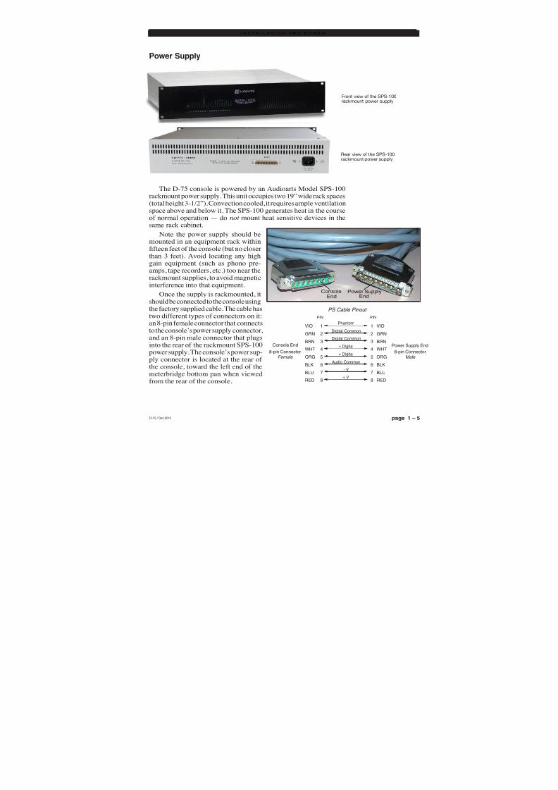
The D-75 console is powered by an Audioarts Model SPS-100rackmount power supply. This unit occupies two 19” wide rack spaces(total height 3-1/2”). Convection cooled, it requires ample ventilationspace above and below it. The SPS-100 generates heat in the courseof normal operation — do not mount heat sensitive devices in thesame rack cabinet.
Note the power supply should bemounted in an equipment rack withinfteen feet of the console (but no closer
than 3 feet). Avoid locating any highgain equipment (such as phono pre-amps, tape recorders, etc.) too near therackmount supplies, to avoid magneticinterference into that equipment.
Once the supply is rackmounted, itshould be connected to the console usingthe factory supplied cable. The cable hastwo different types of connectors on it:an 8-pin female connector that connectsto the console’s power supply connector,
and an 8-pin male connector that plugsinto the rear of the rackmount SPS-100power supply. The console’s power sup-ply connector is located at the rear ofthe console, toward the left end of themeterbridge bottom pan when viewedfrom the rear of the console.
D-75 / Dec 2012
Front view of the SPS-100rackmount power supply
Rear view of the SPS-100rackmount power supply
ConsoleEnd
Power SupplyEnd
1
2
3
4
Phantom
Digital Common
Digital Common+ Digital
NIPNIP
8-pin ConnectorMale
Power Supply End
8-pin ConnectorFemale
Console End
5
6
7
8
+ Digital
Audio Common
- V
+ V
VIO
GRN
BRN
WHT
ORG
BLK
BLU
RED
PS Cable Pinout
1
2
3
4
5
6
7
8
VIO
GRN
BRN
WHT
ORG
BLK
BLU
RED

8/21/2019 D75 MANw_20121207.pdf
http://slidepdf.com/reader/full/d75-manw20121207pdf 17/128
I N S T A L L A T I O N a n d P O W E R
page 1 – 6D-75 / Sep 2004
Note that the power supply is fitted with a 3-wire grounded AC cordthat should be plugged into a "clean" AC power source, that is, an ACsource that feeds only the control room audio gear. This source should bea separate feed from those powering lighting, air-conditioning, or any
other non-audio machinery. The third pin ground wire of the AC sourceshould be tied to the central system ground point.
Energizing
Assuming the D-75 console mainframe is properly placed and grounded,and its SPS-100 power supply correctly rackmounted and connected to theconsole, you may now energize the power supply by plugging it into theAC mains.
Note: To de-energize the console, unplug the rackmount power supply’sAC cord from the AC mains. Never de-energize the console by discon- necting the cable that connects the console and power supply together.
O nce you have ve r i f i ed p rope r pow er -up , unp l ug t he r ackmoun t pow er
supp ly t o d e -ene rg i ze t he c onso l e . You m ay now proceed t o w ir e up au d i o
a n d c o n t r o l c o n n e c t i o n s .
Audio and Control Wiring
All audio and control I/O connections to the D-75 console are madethrough multipin DB-25 connectors located on the top of each module.The factory supplied hand crimping tool is used for all I/O wiring
connections to and from the console (see instruction on the page 1-8).
Connection Procedures
As supplied from the factory, the console requires no logic connectionsto function. Therefore an orderly installation begins with the audio wiring.Note this manual is organized by module type (inputs, outputs, monitormodules, etc.); each chapter contains detailed wiring instructions for itsmodule type. Proceed through the manual, chapter by chapter, until allmodules have been wired to suit your particular installation requirements.Once proper audio operation is verified, go back to each individual chapterand proceed with control wiring.
Digital Audio Connections
CABLE - All AES/EBU input and output digital audio connections arebalanced and should be made using a high quality digital audio cable. Besure to select a digital audio cable with an integral drain wire of the samewire gauge (AWG) as the twisted pair. Typical AES/EBU digital audiocable has a very low characteristic capacitance per ft (pF/ft), and a nominalimpedance of 110Ω. High quality digital audio cable offers better signaltransmission performance versus typical analog audio cable, especiallyover long cable runs. Check the cable manufactures data sheet to be surethe cable you plan to use will work in your application.
D-75 / Apr 2008
The power feed recom-mended in the text is of-ten installed and referredto in studios as an “iso-lated AC ground” outlet.It is usually orange in
color.

8/21/2019 D75 MANw_20121207.pdf
http://slidepdf.com/reader/full/d75-manw20121207pdf 18/128
I N S T A L L A T I O N a n d P O W E R
page 1 – 7D-75 / Sep 2004
CONNECTORS - All AES/EBU connections are made with thesupplied DB-25 connectors. These crimp style connectors will accept wiregauge 24 - 28AWG.
SPDIF INPUTS - The SPDIF (Sony/Phillips Digital Interface) or
“consumer” digital audio interface is a two wire unbalanced signaltypically on a single RCA style connector. We recommend using shieldedtwisted pair cables for these connections. Wire the SPDIF center conduc-tor (HOT) to the SRC-75 “HI” input pin using one wire of the pair and wirethe SPDIF shell (ground) to the SRC-75 “LO” input pin. Connect thecable’s shield to the SRC-75 “SH” pin, leaving the shield floating (that is,not connected) at the SPDIF end.
The SRC-75 digital input audio card is provided with 110Ω /75Ωswitches on the A and B inputs to allow impedance matching with 75Ωsources.
Unbalanced Connections (analog audio)ANALOG INPUTS — Wire to the console with typical shielded two
conductor cable (like Belden 9451), just as if you were connecting abalanced source. At the unbalanced source machine’s output, connect theblack wire (LOW) to the shield. If the machine has a -10 dBu output, don’thesitate to turn module input gain as high as is needed.
ANALOG OUTPUTS — D-75 consoles use a balanced output circuitwhich behaves exactly like the secondary of a high-quality transformer,with no center tap—this output is both balanced and floating. Either theHIGH or LOW side of the output should be strapped to ground, with theoutput taken from the other side. (Normally you’d strap LOW to ground,
and take HIGH to feed your unbalanced equipment.)
Modules Layout
The D-75 console’s mainframe comes supplied with 20 (for 26 pos.frame) or 12 (for 18 pos. frame) input modules along with an outputmodule, a control room module, and a studio control module. Each moduletype has its assigned slot (see drawings on pages 1-10 and 1-11). To handlemic level inputs, a quad mic preamp is included. Also there can be optionalmodules: a superphone, a second quad mic preamp, a line preselect, anda tape remote. Modules must be placed in the slots indicated on the modulelayout drawings that follow.
8/21/2019 D75 MANw_20121207.pdf
http://slidepdf.com/reader/full/d75-manw20121207pdf 19/128
I N S T A L L A T I O N a n d P O W E R
page 1 – 10D-75 / Sep 2004
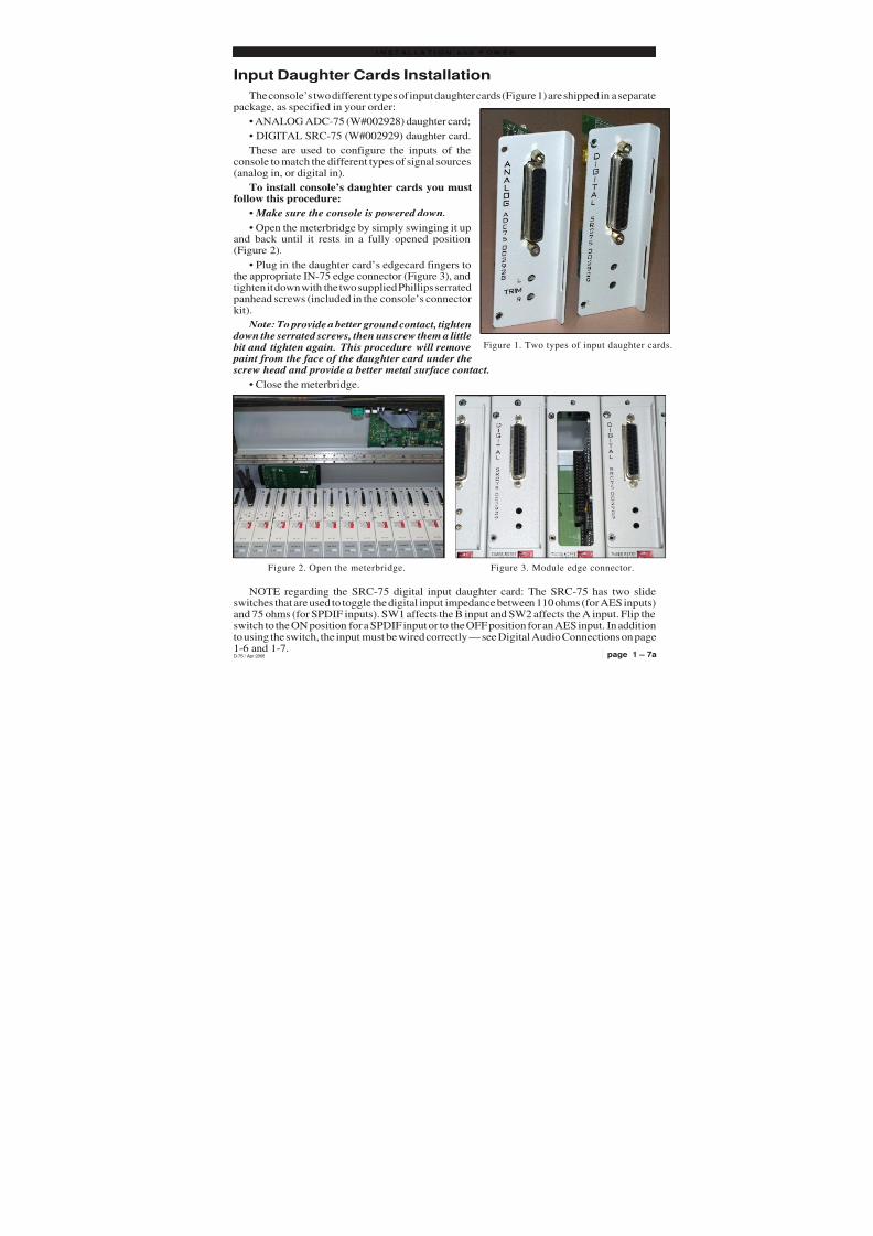
Input Daughter Cards Installation
The console’s two different types of input daughter cards (Figure 1) are shipped in a separatepackage, as specified in your order:
• ANALOG ADC-75 (W#002928) daughter card;
• DIGITAL SRC-75 (W#002929) daughter card.
These are used to configure the inputs of theconsole to match the different types of signal sources(analog in, or digital in).
To install console’s daughter cards you mustfollow this procedure:
• Make sure the console is powered down.
• Open the meterbridge by simply swinging it upand back until it rests in a fully opened position(Figure 2).
• Plug in the daughter card’s edgecard fingers tothe appropriate IN-75 edge connector (Figure 3), andtighten it down with the two supplied Phillips serratedpanhead screws (included in the console’s connectorkit).
Note: To provide a better ground contact, tighten down the serrated screws, then unscrew them a little bit and tighten again. This procedure will remove paint from the face of the daughter card under the screw head and provide a better metal surface contact.
• Close the meterbridge.
NOTE regarding the SRC-75 digital input daughter card: The SRC-75 has two slideswitches that are used to toggle the digital input impedance between 110 ohms (for AES inputs)and 75 ohms (for SPDIF inputs). SW1 affects the B input and SW2 affects the A input. Flip theswitch to the ON position for a SPDIF input or to the OFF position for an AES input. In additionto using the switch, the input must be wired correctly — see Digital Audio Connections on page1-6 and 1-7.
page 1 – 7aD-75 / Apr 2008
Figure 1. Two types of input daughter cards
Figure 3. Module edge connector.Figure 2. Open the meterbridge.

8/21/2019 D75 MANw_20121207.pdf
http://slidepdf.com/reader/full/d75-manw20121207pdf 20/128
I N S T A L L A T I O N a n d P O W E R
page 1 – 8D-75 / Sep 2004
HAND CRIMP TOOL WIRING INSTRUCTIONSThe supplied hand crimping tool (W/S#850067) is used for all I/O wiring con-
nections to and from the console. It is to be used with the supplied pin (figure 1)intended for 22"-28" gauge wire.
1) Strip wire approximately 3/16" (insert inproper wire stripper, rotate one half turn, and
pull insulation off wire).2) Leaving wire aside for the moment, with
crimping tool fully open (engraved side toward
you) bring a terminal into position from the
unmarked side of the tool. Place the conductor tabs (inner set as shown in figure 1) on the"18-22" or "24-30" (depending on the wire) an-
vil (slightly curved surface) so that the circular portion of the tabs rests in the curved surfaceof the anvil and the two tabs face up into the
walls of the female jaw. The insulation tabs willbe flush with the top of the tool (figure 2).
3) Close tool very slightly, only to the point of holding the terminal in position (figure 2).
4) Insert wire into terminal until wire insu-lation is stopped by conductor tabs (figure 3).CRIMP by squeezing handles until jaws are fully
closed (figure 4).5) If there is an insertion error or if a circuit
change is needed, you'll need to use an extrac-tor tool to remove terminals (see next page).
Note that metallized plastic hoods for eachconnector are also supplied with the console.
(1) Pin crimp terminal
CONDUCTOR
TABS
INSULATION
TABS
INSULATION
STOPS HERE
(2) The terminal conductor tabs (pointing UP) areplaced in anvil 18-22; the terminal's insulation tabs
extend in front towards the camera.
(3) The stripped wire is placed into the terminal andcrimped. Note the wire's insulation must stop just
short of the conductor tabs (detail)
(4) Final step: jaws fully closed; the insulation tabshave been crimped.
Insulationstops hereInsulationstops here

8/21/2019 D75 MANw_20121207.pdf
http://slidepdf.com/reader/full/d75-manw20121207pdf 21/128
I N S T A L L A T I O N a n d P O W E R
page 1 – 9D-75 / Sep 2004
(5) Place extractor tip over pin terminal to beremoved.
If you accidentally insert a crimp terminalpin into the wrong socket, you'll need to use
the supplied pin extractor tool (W/S#850069)to remove terminal pin, and correct your mis-
take without having to sacrifice a connector.Place extractor tip (red side) over terminal pin
to be removed (figure 5), and press it down-wards motion until tip rests upon Housing.Then pull out the terminal pin from Housing.
It should never be necessary to discard a con-
nector due to a wiring error.
EXTRACTOR PIN INSTRUCTIONS

8/21/2019 D75 MANw_20121207.pdf
http://slidepdf.com/reader/full/d75-manw20121207pdf 22/128
NOTE: 1. CONSOLE CAN ACCOMMODATE UP TO 21 INPUT MODULES, OR 20 INPUT MODULES PLUS O
2. MASTER OUTPUT, CONTROL ROOM, STUDIO CONTROL AND OPTIONAL SUPERPHONE MOD
3. LAST TWO SLOTS AT THE RIGHT END OF THE FRAME SHOULD BE USED FOR OPTIONAL LIN
D-75-26 CONSOLE - MODULES LAYOUTD-75 / Feb 2005

8/21/2019 D75 MANw_20121207.pdf
http://slidepdf.com/reader/full/d75-manw20121207pdf 23/128
NOTE: 1. CONSOLE CAN ACCOMMODATE UP TO 13 INPUT MODULES, OR 12 INPUT MODULES PLUS ON
2. MASTER OUTPUT, CONTROL ROOM, STUDIO CONTROL AND OPTIONAL SUPERPHONE MODU
3. LAST TWO SLOTS AT THE RIGHT END OF THE FRAME SHOULD BE USED FOR OPTIONAL LINE
D-75-18 CONSOLE - MODULES LAYOD-75 / Feb 2005

8/21/2019 D75 MANw_20121207.pdf
http://slidepdf.com/reader/full/d75-manw20121207pdf 24/128
page 2 – 1D-75 / Sep 2004
Q U A D M I C P R E A M P
Quad Mic Preamp
(QMP-4)
Chapter Contents
Overview ..................................................................................... 2-2
Internal Programming Options ................................................. 2-3
Phantom Power ...................................................................................................... 2-3
Hook-ups..................................................................................... 2-3
Audio Input Connections ........................................................................................ 2-3
Audio Output Connections...................................................................................... 2-4
Power Connections................................................................................................. 2-5
Plug Terminal Pinout Drawing .................................................. 2-6
Installing the Optional Second QMP-4 Mic Preamp ................ 2-7

8/21/2019 D75 MANw_20121207.pdf
http://slidepdf.com/reader/full/d75-manw20121207pdf 25/128
page 2 – 2D-75 / Sep 2004
Q U A D M I C P R E A M P
Quad Mic Preamp(QMP-4)
Overview
The QMP-4 is a quad mono microphone preamplier and is mounted
in the left side of the console meterbridge rear. Mic level sources arewired to QMP-4 mic preamp inputs. QMP-4 output signals are then wiredto input pins of individual IN-75 input modules. IN-75 module A inputsshould be used if you need to have the mic activate control room or studiomuting. The IN-75 must be provided with an ADC-75 daughter card.
Phantom power is available at each input port; it may be selectivelyactivated by a dipswitch SW1 (the factory default is OFF).
Mi c 1
Mi c 2
Mi c 3
Mi c 4

8/21/2019 D75 MANw_20121207.pdf
http://slidepdf.com/reader/full/d75-manw20121207pdf 26/128
page 2 – 3D-75 / Sep 2004
Q U A D M I C P R E A M P
Recessed meterbridge rear trimpots(range 38dB) adjust the level of each input
independently.Example: with a microphone input of
–60dBm @150Ω at the port, gain trim can setlevels from -22dBu to +16dBu (note maximumpreamp gain is +76dB).
All audio input and output signals are made via two 12-position plugterminals mounted on the QMP-4 PCB.
Internal Programming Options
Internal programming for the quad mic preamp is made via printedcircuit board (PCB) mounted seven-position dipswitch SW1. Note thatwhen a dipswitch position is thrown to the right it is ON.
Phantom Power
Dipswitch SW1 turns phantom power on for the four microphone inputports.
SW1 position 7 activates phantom power for microphone 1
SW1 position 5 activates phantom power for microphone 2SW1 position 3 activates phantom power for microphone 3SW1 position 1 activates phantom power for microphone 4
Hook-Ups
As stated before, all user wiring to and from the QMP-4 takes place atthe 12-position plug terminals mounted on the QMP-4 PCB. A pinoutdrawing on page 2-6 shows all wiring connections at a glance.
Audio Input Connections (CT3)
All signals are analog mono. The mic input level is normally -50dBu,balanced.
Pin 1 – Mic 1 In SHPin 2 – Mic 1 In LOPin 3 – Mic 1 In HI
Pin 4 – Mic 2 In SHPin 5 – Mic 2 In LOPin 6 – Mic 2 In HI
Note the factory defaultsetting for phantom power
is OFF.
Mic 1
Mic 2
Mic 3
Mic 4
1
2
3
4
5
6
7
8
9
1 0
1 1
1 2
Typical 12-positionplug terminal
D-75 / Aug 2006

8/21/2019 D75 MANw_20121207.pdf
http://slidepdf.com/reader/full/d75-manw20121207pdf 27/128
page 2 – 4D-75 / Sep 2004
Q U A D M I C P R E A M P
Pin 7 – Mic 3 In SHPin 8 – Mic 3 In LOPin 9 – Mic 3 In HI
Pin 10 – Mic 4 In SHPin 11 – Mic 4 In LOPin 12 – Mic 4 In HI
Audio Output Connections (CT4)
All signals are analog mono. The mic output level is normally +4dBu,balanced.
Pin 12 – Mic 1 Out SHPin 11 – Mic 1 Out LOPin 10 – Mic 1 Out HI
Pin 9 – Mic 2 Out SH
Pin 8 – Mic 2 Out LOPin 7 – Mic 2 Out HI
Pin 6 – Mic 3 Out SHPin 5 – Mic 3 Out LOPin 4 – Mic 3 Out HI
Pin 3 – Mic 4 Out SHPin 2 – Mic 4 Out LOPin 1 – Mic 4 Out HI
Note that each output wires in parallel to the left and right inputchannels of an input stereo module (IN-75) with an analog daughter card(ADC-75).
For example:
Pin 25 - Line A Lt In SH
Pin 12 – Mic 1 Out SH wires to
Pin 11 - Line A Rt In SH
Pin 12 - Line A Lt In LOPin 11 – Mic 1 Out LO wires to
Pin 23 - Line A Rt In LO
Pin 24 - Line A Lt In HIPin 10 – Mic 1 Out HI wires to
Pin 10 - Line A Rt In HI
1
2
3
4
5
6
7
8
9
1 0
1 1
1 2
Typical 12-positionplug terminal

8/21/2019 D75 MANw_20121207.pdf
http://slidepdf.com/reader/full/d75-manw20121207pdf 28/128
page 2 – 5D-75 / Sep 2004
Q U A D M I C P R E A M P
Power Connections (CT7)
A ribbon cable connects the 10-pin connector on the QMP-4 (CT7) to the10-pin connector mounted at the right end of the MBR-75 motherboard(CT2) to provide power to the microphone preamplifier.
Pin 1 – Analog GroundPin 2 – Analog GroundPin 3 - +Phantom VPin 4 – +Phantom VPin 5 – +V InPin 6 – +V InPin 7 – -V InPin 8 – -V InPin 9 – Analog GroundPin 10 – Analog Ground

8/21/2019 D75 MANw_20121207.pdf
http://slidepdf.com/reader/full/d75-manw20121207pdf 29/128
page 2 – 6D-75 / Sep 2004
Q U A D M I C P R E A M P
1
2
3
4
5
6
7
8
9
1 0
1 1
1 2
QMP-4 Quad Mic Preamp Plug Terminal Pinouts
INPUT
PORTS ANALOG
MIC 1 IN SH
MIC 1 IN LO
MIC 1 IN HI
MIC 2 IN SH
MIC 2 IN LO
MIC 2 IN HI
MIC 3 IN SH
MIC 3 IN LO
MIC 3 IN HI
MIC 4 IN SH
MIC 4 IN LO
MIC 4 IN HI
1
2
3
4
5
6
7
8
9
1 0
1 1
1 2
OUTPUTPORTS
ANALOG
MIC 4 OUT HI
MIC 4 OUT LO
MIC 4 OUT SH
MIC 3 OUT HI
MIC 3 OUT LO
MIC 3 OUT SH
MIC 2 OUT HI
MIC 2 OUT LO
MIC 2 OUT SH
MIC 1 OUT HI
MIC 1 OUT LO
MIC 1 OUT SH

8/21/2019 D75 MANw_20121207.pdf
http://slidepdf.com/reader/full/d75-manw20121207pdf 30/128
page 2 – 7D-75 / Sep 2004
Q U A D M I C P R E A M P
Installing the Optional Second QMP-4 Mic Preamp
The optional second QMP-4 comes complete with mounting hardware.The ribbon cable, installed at the factory to provide power to the pre-installedQMP-4 card, also includes a second plug (“Connector” on the picture above)for connecting the optional QMP-4 card. Handle the 10-pin plug on theribbon cable assembly with care. Perform the following steps to install theQMP-4:
• turn off the power to the console;
• swing the meterbridge up and back until it rests in a fully openedposition;
• plug in the ribbon cable connector to the 10-pin boxed header on theQMP-4 board (CT7);
• attach the QMP-4 preamp assembly directly to the right of the factoryinstalled preamp (located at the lefthand end of the meterbridge), using fourtype 4-40x1/4 pan head screws and four nylon standoffs through the fourpredrilled holes on the meterbridge rear (“Optional QMP-4 Area” on thepicture above); orient it to match the factory installed QMP-4;
• connect the required audio wiring to the 12-pin plug terminals on the
QMP-4 card, referring to the “Hook-Ups” chart (see pages 2-3 - 2-5);• close the meterbridge.
This completes the optional QMP-4 installation procedure.
Optional
QMP-4 Area
Connector
D-75 / May 2008

8/21/2019 D75 MANw_20121207.pdf
http://slidepdf.com/reader/full/d75-manw20121207pdf 31/128
page 3 – 1D-75 / Sep 2004
S T E R E O L I N E I N P U T
Stereo Line Input
(IN-75)
Chapter Contents
Module Overview........................................................................ 3-2
Internal Programming Options ................................................. 3-3
Mutes ...................................................................................................................... 3-3
Tallies...................................................................................................................... 3-3
Timer Restart .......................................................................................................... 3-3
Talkback.................................................................................................................. 3-3
Attenuation.............................................................................................................. 3-4
EFS - European Fader Start ................................................................................... 3-4
Hook-ups..................................................................................... 3-4
Analog Audio Connections ..................................................................................... 3-4
Digital Audio Connections ...................................................................................... 3-5
Control Connections ............................................................................................... 3-5
Remote ON & OFF ............................................................................................ 3-5
Cough ................................................................................................................ 3-5
External START & STOP .................................................................................. 3-6
Ready................................................................................................................. 3-6
Talkback to Control Room ................................................................................. 3-6
On Tally ............................................................................................................. 3-6
Tally B ................................................................................................................ 3-6
DB Connector Pinout Drawings
Analog Inputs - ADC-75 .......................................................................................... 3-7
Digital Inputs - SRC-75 ........................................................................................... 3-8
Stereo Line Input Signal Flow ................................................... 3-9

8/21/2019 D75 MANw_20121207.pdf
http://slidepdf.com/reader/full/d75-manw20121207pdf 32/128
page 3 – 2D-75 / Sep 2004
S T E R E O L I N E I N P U T
Stereo Line Input(IN-75)
Module Overview
IN-75 modules are for mic inputs signals (from the QMP-4) and stereoline input signals.
At the top of the module, underneath the hinged meterbridge, is a plug-in daughter card that determines if the module is a digital input (SRC-75)or an analog input (ADC-75). If the module is being used to handle micsignals from the QMP-4, it will need to have the ADC-75 daughter card.
The ADC (analog-to-digital converter) version accepts +4dBu bal-anced analog input signals. PCB-mounted multi-turn trimpots adjust theleft and right levels.
The SRC (sample rate converter) version accepts digital (AES isfactory default) input signals.
Each module accepts two stereo sources, A and B, switched at the topof the module. Output switches assign the selected source signal to any
combination of the console’s four stereo outputs—PGM (program),AUD (audition), AUX (auxiliary), and UTIL (utility). Please note, theUTIL bus is pre-fade, pre-on. This feature can be defeated (seepage 10-4).
A CUE switch places the module’s signal on the console’s cue bus,where it may be heard on the meterbridge mounted cue speaker and/or asan interrupt to the console operator’s headphones and/or control roommonitor speakers. The various cue interrupt modes are programmed at theconsole’s CR-75 (Control Room) module via PCB-mounted dipswitch.See page 5-3.
Level is set by a long-throw fader.
Channel ON (START) and OFF (STOP) switches are at the bottom of the module. In addition to being controlled remotely, these can also beprogrammed (via internal PCB-mounted dipswitch) to perform a varietyof functions, including starting and stopping external source machines,activating control room and studio mutes, external tallies, and timerrestart. The STOP switch’s LED can be controlled by an external sourcemachine to act as a “ready” indicator.
All audio and control input and output signals are made via the multi-pin DB-25 connector mounted on the top of the module and locatedunderneath the hinged meterbridge.
D-75 / Feb 2005

8/21/2019 D75 MANw_20121207.pdf
http://slidepdf.com/reader/full/d75-manw20121207pdf 33/128
page 3 – 3D-75 / Sep 2004
S T E R E O L I N E I N P U T
Internal Programming Options
With the exception of UTIL pre-fade/pre-on defeat and B follow optionsmentioned below, all internal programming is made via PCB mounted dipswitchSW1 located on the top of the module (beneath the DB-25 connector). Note that
when a dipswitch position is thrown to the right it is ON.
Mutes
An IN-75 module can be programmed to mute speakers when the channel is ON.The D-75 console has two mute control lines: control room and studio. Each of theseis activated by an A input source.
SW1 position 6 mutes the control room when source A is ONSW1 position 5 mutes the studio when source A is ON
If the MUTE B setting is made on the PR-75 (see page 10-5) then the mutes willalso function when source B is used.
Tallies
The console has two tallies. The ON-AIR TALLY (see CR-75 chapter) isactivated whenever the control room mute is activated. TALLY 2 (see SC-75chapter) is activated separately, according to the setting of the dipswitch, by an Ainput source.
SW1 position 4 activates tally 2 when source A is ON
If the MUTE B setting is made on the PR-75 (see page 10-5) then the tallies willalso function when source B is used.
Timer Restart
The console’s digital timer can be programmed to automatically reset to zero and
begin counting up when the module’s ON button is pressed.SW1 position 7 activates timer restart
If the TMR B setting is made on the PR-75 (see page 10-5) then the timer restartwill also function when source B is used.
Talkback
Typically, one of the D-75 console’s input modules will be used for the controlroom (CR) console operator’s microphone. The third position of the dipswitch SW1allows that microphone to also function as a talkback mic. It places the signal (pre-fader, pre-on/off) onto the console’s talkback bus. When the console operatorpresses a TB switch on the console’s SC-75 studio module, the talkback bus (which
is carrying his microphone signal) will interrupt the regular monitor signal being fedto the studio and talent will hear his voice through the studio monitor speakers.
To accommodate those situations where more than one operator microphone isused, any number of IN-75 input modules may be assigned to feed the talkback bus.
SW1 position 3 allows the module’s audio to feed the talkback bus
In order for the studio to reply to the console operator, the IN-75 modulecontrolling the studio’s microphone signal must be routed to the console’s cue bus,where it can be heard by the operator. This is accomplished by a user-supplied TBswitch in the studio. The switch provides a momentary closure between the module’sDB-25 connector “TB to CR” control pin and Digital Ground (see page 3-6 for wiring
?
D-75 / Jan 2008

8/21/2019 D75 MANw_20121207.pdf
http://slidepdf.com/reader/full/d75-manw20121207pdf 34/128
page 3 – 4D-75 / Sep 2004
S T E R E O L I N E I N P U T
details). As long as this closure is maintained (i.e., as long as talent holds downthe studio TB button) the module’s (pre-fader, pre-on/off) signal will be placedon the console’s Cue bus.
Attenuation
As mentioned in the Read Me! pages at the front of the manual, there is atendency today for CD’s to be made with less than 1dB of headroom. Anyboosting of level resulting from moving the fader up from the nominal, unity gain,position results in overload distortion. For this reason, dipswitch position 2 isprovided to attenuate a channel’s signal by 12dB, thus allowing channels beingfed by such hot CD’s to have their faders moved above nominal without causingdistortion. The 12dB attenuation is applied to the four main stereo buses, cue, andtalkback — in other words, anywhere in the console that the channel’s audio maybe routed.
SW1 position 2 applies 12dB of attenuation to the channel for all bus feeds
EFS - European Fader Start
In some situations it is desirable to have the channel’s on/off status controlledby the position of the fader. In such a scenario, if the fader is all the way down andthe channel is off, moving the fader up slightly from the full down position willturn the channel on without the need to press the channel ON button. In a similarmanner, if the fader is up from the full down position by at least a small amountand the channel is on, moving the fader to the full down position will turn thechannel off without the need to press the channel OFF button. This feature isenabled by moving the dipswitch position 1 to the right (on).
SW1 position 1 enables the EFS feature
Hook-UpsAs stated before, all user wiring to and from IN-75 modules takes place at the
DB-25 multi-pin connector mounted on the daughter card at the top of eachmodule. There is one connector per module. Pinout drawings on pages 3-7 and3-8 show all wiring connections at a glance.
Audio Connections — Analog Inputs (ADC-75)
These include A and B source inputs; level is +4dBu balanced.
Pin 25 – Line A Lt In SHPin 24 – Line A Lt In HI
Pin 12 – Line A Lt In LO
Pin 11 – Line A Rt In SH
Pin 10 – Line A Rt In HIPin 23 – Line A Rt In LO
Pin 22 – Line B Lt In SHPin 21 – Line B Lt In HIPin 9 – Line B Lt In LO
Pin 8 – Line B Rt In SHPin 7 – Line B Rt In HIPin 20 – Line B Rt In LO
Typical DB-25connector
D-75 / Jan 2008
8/21/2019 D75 MANw_20121207.pdf
http://slidepdf.com/reader/full/d75-manw20121207pdf 35/128
page 3 – 5D-75 / Sep 2004
S T E R E O L I N E I N P U T
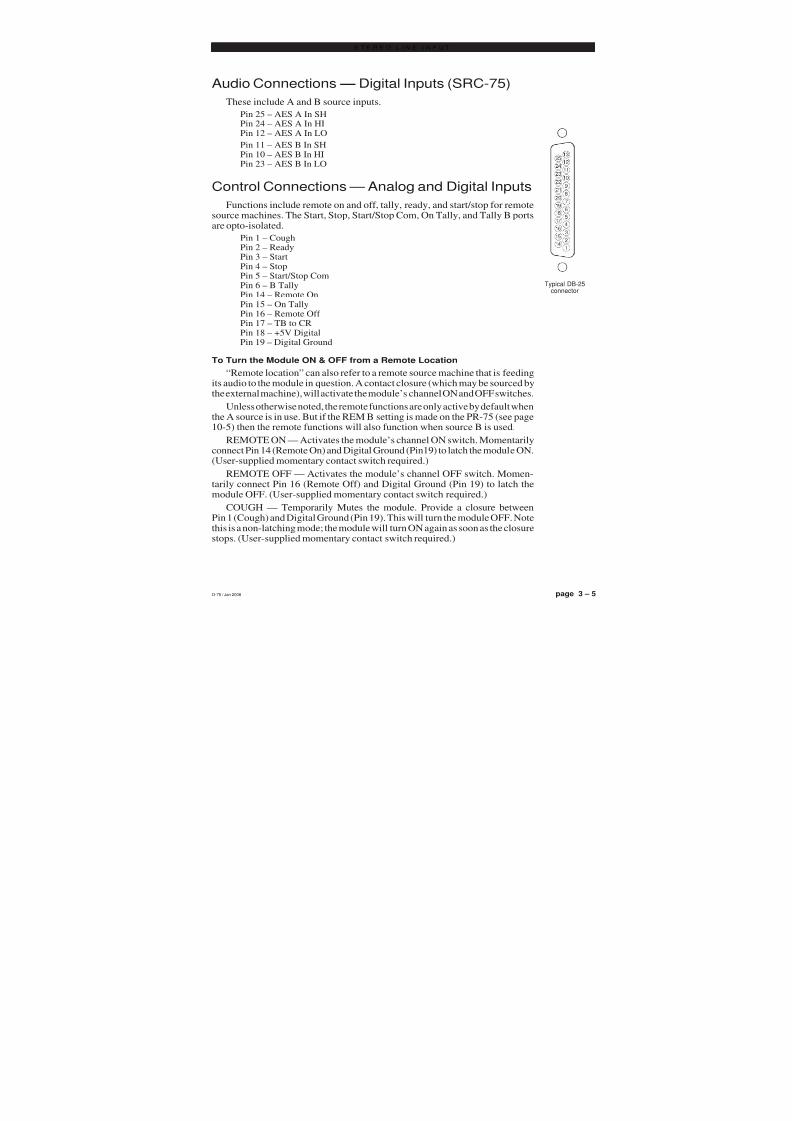
Audio Connections — Digital Inputs (SRC-75)
These include A and B source inputs.
Pin 25 – AES A In SHPin 24 – AES A In HIPin 12 – AES A In LO
Pin 11 – AES B In SHPin 10 – AES B In HIPin 23 – AES B In LO
Control Connections — Analog and Digital Inputs
Functions include remote on and off, tally, ready, and start/stop for remotesource machines. The Start, Stop, Start/Stop Com, On Tally, and Tally B portsare opto-isolated.
Pin 1 – CoughPin 2 – ReadyPin 3 – StartPin 4 – StopPin 5 – Start/Stop ComPin 6 – B TallyPin 14 – Remote OnPin 15 – On TallyPin 16 – Remote Off Pin 17 – TB to CRPin 18 – +5V DigitalPin 19 – Digital Ground
To Turn the Module ON & OFF from a Remote Location“Remote location” can also refer to a remote source machine that is feeding
its audio to the module in question. A contact closure (which may be sourced bythe external machine), will activate the module’s channel ON and OFF switches.
Unless otherwise noted, the remote functions are only active by default whenthe A source is in use. But if the REM B setting is made on the PR-75 (see page10-5) then the remote functions will also function when source B is used.
REMOTE ON — Activates the module’s channel ON switch. Momentarilyconnect Pin 14 (Remote On) and Digital Ground (Pin19) to latch the module ON.(User-supplied momentary contact switch required.)
REMOTE OFF — Activates the module’s channel OFF switch. Momen-
tarily connect Pin 16 (Remote Off) and Digital Ground (Pin 19) to latch themodule OFF. (User-supplied momentary contact switch required.)
COUGH — Temporarily Mutes the module. Provide a closure betweenPin 1 (Cough) and Digital Ground (Pin 19). This will turn the module OFF. Notethis is a non-latching mode; the module will turn ON again as soon as the closurestops. (User-supplied momentary contact switch required.)
Typical DB-25connector
D-75 / Jan 2008
8/21/2019 D75 MANw_20121207.pdf
http://slidepdf.com/reader/full/d75-manw20121207pdf 36/128
page 3 – 6D-75 / Sep 2004
S T E R E O L I N E I N P U T
To START and STOP Remote Source Machines Using Module ON/OFF
Switches
EXTERNAL START — Hook up the remote machine’s “start” control pins to theIN-75 module’s DB-25 connector control pins: for START wire to Pins 3 and 5.
EXTERNAL STOP — Hook up the remote machine’s “stop” control pins to theIN-75 module’s DB-25 connector control pins: for STOP wire to Pins 4 and 5.
These are opto-isolated outputs.
To Control the Module’s OFF Switch LED with an External Source Machine
READY — Hook up the remote machine’s Ready output to the IN-75 module’sDB-25 connector pin 2 (Ready) and pin 19 (Digital Ground). The module’s Ready portis looking for a contact closure. As long as the closure is maintained, the module’s OFFLED illumination will be opposite what it normally is. That is, if the OFF LED isexpected to be lit (module off) the external closure will turn that LED off, whereas if the OFF LED is expected to be off (module on) the external closure will turn the LED
on. As a result, the OFF LED will flash when a pulse is connected to the Ready input.
Talkback to Control Room
If an IN-75 module is being used for a studio microphone, this connection allowstalkback from that studio to the console operator. Provide a closure between Pin 17(TB to CR) and Digital Ground (Pin 19). This will cause the module’s pre fader signalto be sent to the console’s Cue bus, where it may be heard by the console operator. Thisnon-latching condition continues until the closure is released. (Requires user-suppliedmomentary action TALKBACK switch at the studio microphone location.)
On Tally
Lets the module’s channel ON switch control an on-air light or other “microphone
on” indicator at a remote location. This control function provides a continuous closureto Digital Ground at Pin 15 (On Tally) whenever the module is ON.
This closure can be used to control an externally powered tally light that requiresa continuous closure to function. Or an external tally light (i.e., LED) can be poweredfrom the input module by connecting the external LED to +5V Digital (Pin 18) and theOn Tally port. In either case the current should not exceed 30 milliamps.
Tally B
Provides a remote indication that the module’s B source has been selected. Thiscontrol function provides a continuous closure (open collector) between Pin 6(Tally B) and Digital Ground (Pins 19) whenever the B source is selected.
This closure can be used to control an externally powered tally light that requiresa continuous closure to function. An external tally light (i.e., LED) can be poweredfrom the input module by connecting the external LED to +5V Digital (Pin 18) and theB Tally port. The current should not exceed 30 milliamps.
Note that this output always functions regardless of the REM B setting on thePR-75. However, you will most likely want to enable B remote logic if you are usingthe B Tally.
D-75 / Jan 2008

8/21/2019 D75 MANw_20121207.pdf
http://slidepdf.com/reader/full/d75-manw20121207pdf 37/128
page 3 – 7D-75 / Sep 2004
S T E R E O L I N E I N P U T
D-75 / Feb 2005
IN-75 Analog Input - ADC-75 DB Connector Pinouts
I/O PORT ANALOG
AND LOGIC
LINE A LT IN HI
LINE A RT IN LO
LINE B LT IN HI
LINE B RT IN LO
DIGITAL GROUND
+5V DIGITAL
TB TO CR
REMOTE OFF
ON TALLY
REMOTE ON
AUDIO GROUND
LINE A LT IN LO
LINE A RT IN SH
LINE A RT IN HI
LINE B LT IN LO
LINE B RT IN SH
LINE B RT IN HI
TALLY B
START/STOP COMMON
STOP
STARTREADY
COUGH
5
4
32
1
17
16
15
14
8
7
6
20
19
18
10
9
23
22
21
13
12
11
2524
LINE A LT IN SH
LINE B LT IN SH

8/21/2019 D75 MANw_20121207.pdf
http://slidepdf.com/reader/full/d75-manw20121207pdf 38/128
page 3 – 8D-75 / Sep 2004
S T E R E O L I N E I N P U T
IN-75 Digital Input - SRC-75 DB Connector Pinouts
I/O PORTS DIGITAL
AND LOGIC
AES A IN HI
AES B IN LO
N/C
N/C
DIGITAL GROUND
+5V DIGITAL
TB TO CR
REMOTE OFF
ON TALLY
REMOTE ON
AUDIO GROUND
AES A IN LO
AES B IN SH
AES B IN HI
N/C
N/C
N/C
TALLY B
START/STOP COMMON
STOP
STARTREADY
COUGH
5
4
32
1
17
16
15
14
8
7
6
20
19
18
10
9
23
22
21
13
12
11
2524
AES A IN SH
N/C

8/21/2019 D75 MANw_20121207.pdf
http://slidepdf.com/reader/full/d75-manw20121207pdf 39/128
ON
OFF
START
STOPA/B TALLYREADY
A / B
LOGIC
A
LOGIC
ONA/B
PGM AUD AUX
CHANNEL ON/OFFINPUT SELECT
BUS ASSIGN SWITCHES
FRONT PANEL SWITCHES
LOGIC
A Logic Follow
LOGIC
PORTS
CR MUTE
STUDIO MUTE
TALLY 2
ATTENUATE
T O C O N S O L E C O N T R O L B U S S E S
TIMER RESTART
TB TO STUDIO
EFS
D-75 / Jan 2008IN-75 Stereo Line Input Module - Signal Flow Diagram
CUE
FADER
DIGITAL AUDIO
DATA
CUE ASSIGN CUE LOGIC
V D I P
S W I T C H
STEREO LINE INPUT
ANALOG OR DIGITAL
L
H
L
H
L
H
LH
A
BR
L
R
L
R
L
SELECT
TRIM
TRIM
INPUT
FET
SW
AB
ANALOG TO
DIGITAL
CONVERTER
(ADC)
Analog
Analog
Analog
Analog
A
BINPUT Digital
DigitalAES
RECEIVER
SAMPLE
RATE
CONVERTER
(SRC)
OR
SELECT
AB
OFF
UTIL
pag
ADC-75
DAUGHTER CARD
SRC-75
DAUGHTER CARD
AIR TALLY
ON TALLY
COUGHTB TO CR
PREAMP(MONO)
MIC 1
MIC 2
MIC 3
MIC 4
TO LINE INPUT
CHANNEL
QMP-4
MIC PREAMP
UTIL PRE/POST
B Logic Follow
Options

8/21/2019 D75 MANw_20121207.pdf
http://slidepdf.com/reader/full/d75-manw20121207pdf 40/128
page 4 – 1D-75 /Sep 2004
O U T P U T M O D U L E
Output Module
(OM-75)Chapter Contents
Module Overview........................................................................ 4-2
Internal Programming Options ................................................. 4-3
Sampling Frequency for Console Outputs .............................. 4-3
Hook-ups..................................................................................... 4-4
Left DB-25 “B” Connector — Digital Audio Outputs, External Analog Inputs ........ 4-4
Right DB-25 “A” Connector — Analog Audio Outputs ........................................... 4-4
DB Connector Pinout Drawing .................................................. 4-6
Output Module Signal Flow ....................................................... 4-7

8/21/2019 D75 MANw_20121207.pdf
http://slidepdf.com/reader/full/d75-manw20121207pdf 41/128
page 4 – 2D-75 /Sep 2004
O U T P U T M O D U L E
Output Module(OM-75)
Module Overview
The master output module handles the console’s Program, Audi-tion, Auxiliary, and Utility outputs. All analog outputs are calibratedwith recessed front panel multi-turn trimpots.
The D-75 console has two pairs of left-right VU meters, PGM andSWT (switched), located on the console’s meterbridge. The switchedmeter follows the SELECT switching, allowing the console operator tometer AUD, AUX and UTIL, and two external stereo line signals(analog, +4dBu balanced), which may be brought into the module onits DB-25 connector.
The OM-75 also has a master CUE ON indicator. Whenever anyinput module is placed in cue the CUE ON indicator lights. At the sametime the switched meter pair automatically switches to show the levelof audio on the cue bus. While the CUE ON indicator is lit, the selectedswitched meter source switch light goes off.
At the bottom of module are the timer control buttons (the timerdisplay is mounted in the righthand end of the console meterbridge):
AUTO START – enables timer restart functions from programmed inputmodules’ ON buttons.
START/STOP - halts the timer, holds the last count, and then restarts andaccumulates the count when depressed again.
RESET - return to zero (if the timer is stopped it will hold at zero; if it isrunning it will reset to zero and immediately begin counting up).
HOLD – when held down freezes the timer display (the counter keeps ongoing); when released the display catches up to the current count.
All user wiring to and from the OM-75 module takes place at thetwo DB-25 multi-pin connectors mounted on top of the module andlocated underneath the hinged meterbridge. All analog audio is +4dBubalanced. Pinout drawing on page 4-6 shows all wiring connections ata glance.

8/21/2019 D75 MANw_20121207.pdf
http://slidepdf.com/reader/full/d75-manw20121207pdf 42/128
page 4 – 3D-75 /Sep 2004
O U T P U T M O D U L E
Internal Programming Options
There are no programming options on the OM-75 output card.
Sampling Frequency for Console OutputsFor stand alone operation, the console output sample rate is determined
by crystal Y1, which is installedat the factory for a 44.1 kHzsample rate. An additional crys-tal oscillator is provided with theconsole for the 48 kHz samplerate. Crystals for the 32 kHzsample rate are available fromthe factory as a special orderitem.
To switch to a different out-put sample rate, replace crystalY1 with one of the appropriatefrequency as shown in Figure 1and Table 1.
TABLE 1
SAMPLE RATE CRYSTAL OSCILLATOR WS PART#
FREQUENCY
48 kHz 24.576 MHz 370012
44.1 kHz 22.579 MHz 370011
32 kHz 16.384 MHz 370010
Note that to replace the crystal Y1 you need to open the meterbridge toaccess the PR-75 board.
The console must be powered down before changing the sample ratecrystal Y1 or damage not covered by warranty may result. Changing thecrystal Y1 will change the console output sample rate; however some externaldigital devices also need the correct sample rate information to be embeddedin the AES output data or they will not operate correctly. Therefore, afterchanging the sample rate crystal Y1, be sure to reset dipswitches SW3 and
SW4 on the PR-75 board to correctly embed the sample rate information inthe output AES data stream. Table 2 shows the dipswitch settings.
TABLE 2
SW3 SW4 FREQUENCY
OFF OFF 48 kHz
ON OFF *44.1 kHz
OFF ON 32 kHz
*default setting
Figure 1. Section of the PR-75 PCB
SW3 SW4
D-75 /Nov 2009
!Note, the console sample ratecan also be synchronized to anexternal sample rate source.See page 10-5 for details.

8/21/2019 D75 MANw_20121207.pdf
http://slidepdf.com/reader/full/d75-manw20121207pdf 43/128
page 4 – 4D-75 /Sep 2004
O U T P U T M O D U L E
Typical DB-25
connector
Hook-Ups
As stated before, all user wiring to and from the OM-75 module takes placeat two DB-25 multi-pin connectors at the top of module.
Left DB-25 “B” Connector – Digital Audio Outputs and External Analog Inputs
Handles External inputs and Program, Audition, Auxiliary, and Utility digitaloutputs. The external analog input signals are +4dBu balanced.
Pin 25 – PGM AES Out SHPin 24 – PGM AES Out HIPin 12 – PGM AES Out LO
Pin 11 – AUD AES Out SHPin 10 – AUD AES Out HI
Pin 23 – AUD AES Out LOPin 22 – AUX AES Out SHPin 21 – AUX AES Out HIPin 9 – AUX AES Out LO
Pin 8 – UTIL AES Out SHPin 7 – UTIL AES Out HIPin 20 – UTIL AES Out LO
Pin 19 – Ext 1 Lt In SHPin 18 – Ext 1 Lt In HIPin 6 – Ext 1 Lt In LO
Pin 5 – Ext 1 Rt In SHPin 4 – Ext 1 Rt In HI
Pin 17 – Ext 1 Rt In LOPin 16 – Ext 2 Lt In SHPin 15 – Ext 2 Lt In HIPin 3 – Ext 2 Lt In LO
Pin 2 – Ext 2 Rt In SHPin 1 – Ext 2 Rt In HIPin 14 – Ext 2 Rt In LO
Right DB-25 “A” Connector – Analog Audio Outputs
Handles Program, Audition, Auxiliary, and Utility analog outputs.
All signals are +4dBu balanced.Pin 25 – PGM Lt Out SHPin 24 – PGM Lt Out HIPin 12 – PGM Lt Out LO
Pin 11 – PGM Rt Out SHPin 10 – PGM Rt Out HIPin 23 – PGM Rt Out LO
Pin 22 – AUD Lt Out SHPin 21 – AUD Lt Out HIPin 9 – AUD Lt Out LO

8/21/2019 D75 MANw_20121207.pdf
http://slidepdf.com/reader/full/d75-manw20121207pdf 44/128
page 4 – 5D-75 /Sep 2004
O U T P U T M O D U L E
Pin 8 – AUD Rt Out SHPin 7 – AUD Rt Out HIPin 20 – AUD Rt Out LO
Pin 19 – AUX Lt Out SH
Pin 18 – AUX Lt Out HIPin 6 – AUX Lt Out LO
Pin 5 – AUX Rt Out SHPin 4 – AUX Rt Out HIPin 17 – AUX Rt Out LO
Pin 16 – UTIL Lt Out SHPin 15 – UTIL Lt Out HIPin 3 – UTIL Lt Out LO
Pin 2 – UTIL Rt Out SHPin 1 – UTIL Rt Out HIPin 14 – UTIL Rt Out LO
Typical DB-25connector

8/21/2019 D75 MANw_20121207.pdf
http://slidepdf.com/reader/full/d75-manw20121207pdf 45/128
page 4 – 6D-75 /Sep 2004
O U T P U T M O D U L E
OM-75 Output Module DB Connector Pinouts
9
10
11
12
13
22
23
24
25
6
7
8
1920
21
4
5
16
17
18
1
2
3
14
15
EXT2 RT IN HI
EXT2 RT IN SH
EXT2 LT IN LO
EXT1 RT IN HI
EXT1 RT IN SH
EXT1 LT IN LO
UTIL AES OUTHI
UTIL AES OUT SH
AUX AES OUT LO
AUD AES OUT HI
AUD AES OUT SH
PGM AES OUT LO
EXT2 RT IN LO
EXT2 LT IN HI
EXT2 LT IN SH
EXT1 RT IN LO
EXT1 LT IN HI
EXT1 LT IN SHUTIL AES OUTLO
AUX AES OUT HI
AUX AES OUT SH
AUD AES OUT LO
PGM AES OUT HI
PGM AES OUT SHAUDIO GROUND
9
10
11
12
13
22
23
24
25
6
7
8
19
20
21
4
5
16
17
18
1
2
3
14
15
I/O PORTS(Left DB-25 "B")
I/O PORTS(Right DB-25 "A")
UTIL RT OUT HI
UTIL RT OUT SH
UTIL LT OUT LO
AUX RT OUT HI
AUX RT OUT SHAUX LT OUT LO
AUD RT OUT HI
AUD RT OUTSH
AUD LT OUT LO
PGM RT OUT HI
PGM RT OUT SH
PGM LT OUT LO
UTIL RT OUT LO
UTIL LT OUT HI
UTIL LT OUT SH
AUX RT OUT LO
AUX LT OUT HI
AUX LT OUT SH
AUD RT OUT LO
AUD LT OUT HI
AUD LT OUT SH
PGM RT OUT LO
PGM LT OUT HI
PGM LT OUT SHAUDIO GROUND

8/21/2019 D75 MANw_20121207.pdf
http://slidepdf.com/reader/full/d75-manw20121207pdf 46/128
F R O M
D S P
T O C O
N S O L E
M E T E R S
D-75 / Sep 2004 OM-75 Output Module - Signal Flow Diagram
TEL MONITOR TEL MONITOR
LH
AUD DIG OUT
CUE
L
R
CUE LT
MONITOR
CUE RT
MONITOR
DAC
DAC
SWITCHED DATAAUDITION
L
R
AUD LTOUTLH
AUD RT
OUTLH
DAC
AUXILIARY
L
R
AUX LT
OUTLH
AUX RTOUTL
H
DAC
UTILITY
L
R
UTIL LT
OUTLH
UTIL RTOUTL
H
DAC
CUE LOGIC
FROM CONSOLE
CONTROL BUSSES
S
W
I
T
C
H
E
D
V
U
S
E
L
E
C
T
OM-75
FRONT PANEL
SWITCHES
VU
SELECT
LOG
IC
EXT2
AUD
AUX
UTIL
page 4
PROGRAM
L
R
PGM LT
OUTLH
PGM RT
OUTLH
DAC
PGM DATA
LH
AUX DIG OUT
LH
UTIL DIG OUT
LH
PGM DIG OUT
EXT1
PGM MONITOR
AUD MONITOR
AUX MONITOR
UTIL MONITOR
PGM
AUD
UTIL
AUX
CUE
TEL
8/21/2019 D75 MANw_20121207.pdf
http://slidepdf.com/reader/full/d75-manw20121207pdf 47/128
page 5 – 1D-75 / Sep 2004
C O N T R O L R O O M M O D U L E
Control Room Module
(CR-75)
Chapter Contents
Module Overview...........................................................................5-2
Internal Programming Options ....................................................5-3
Cue Interrupt ............................................................................................................. 5-3
CR/Cue Mute ............................................................................................................ 5-3
On-Air Tally Follows Program................................................................................... 5-3
Hook-ups........................................................................................5-4
Left DB-25 “B” Connector — Audio .......................................................................... 5-4
Right DB-25 “A” Connector — Audio and On-Air Tally ............................................ 5-4
DB Connector Pinout Drawing.....................................................5-5
Control Room Module Signal Flow..............................................5-6

8/21/2019 D75 MANw_20121207.pdf
http://slidepdf.com/reader/full/d75-manw20121207pdf 48/128
page 5 – 2D-75 / Sep 2004
C O N T R O L R O O M M O D U L E
Control Room Module(CR-75)
Module Overview
The CR-75 module is the D-75 console operator’s monitor module. Itallows the operator to listen to the console’s four stereo outputs (PGM,AUD, AUX, & UTIL) and two external stereo line level inputs broughtdirectly into the module.
The CUE master level control sets the level of the console’s cue signal.
Whenever CUE is activated elsewhere on the console (stereo line inputs or thesuperphone module) its signal will appear at the console’s built-in cue speakermounted in the meterbridge. Depending on how the CR-75 module has beenprogrammed, cue can also interrupt the control room monitor speakers and theheadphones. The way Cue interrupts the control room and headphone outputs isdetermined by PCB-mounted dipswitch. See “Cue Interrupt” on page 5-3.
The CR-75 module also houses control room and headphone monitorcircuits, which follow the source selection switches:
CONTROL ROOM (CR)—a dedicated output designed to drive aseparate, user provided power amp/speaker system in the main controlroom;
HEADPHONE (HDPN)—an additional output (w/built-in power amp)that drives the console operator’s headphones. There are two types of headphone output: the +4dBu balanced output at the module’s rightDB-25 connector (A), and the headphone jack mounted in the right-handcorner of the console, which is actually the output from a built-inheadphone amplifier.
All user wiring to and from the CR-75 module takes place at theDB-25 multi-pin connectors mounted at the top of the module and locatedunderneath the hinged meterbridge. There are two connectors: the left oneaccepts the two stereo analog external inputs; the right one handles thecontrol room, headphone pre, and stereo cue pre outputs, and the air tallyrelay. All audio connections are stereo line level analog signals. A pinoutdrawing on page 5-5 shows all wiring connections at a glance.
8/21/2019 D75 MANw_20121207.pdf
http://slidepdf.com/reader/full/d75-manw20121207pdf 49/128
page 5 – 3D-75 / Sep 2004
C O N T R O L R O O M M O D U L E
Internal Programming Options
Internal programming for the control room module is made via printedcircuit board (PCB) mounted dipswitch SW1 located on the top of the
module (beneath the DB-25 connectors). Note when a dipswitch positionis thrown to the right it is ON.
Cue Interrupt
Dipswitch SW1 pos. 2-5 determines how the console’s Cue functionwill interrupt control room and headphone signals:
SW1 position 5 sends cue to CR leftSW1 position 4 sends cue to CR rightSW1 position 3 sends cue to HDPN leftSW1 position 2 sends cue to HDPN right
Note that when cue is only set to interrupt one side of an output (for
example, SW1 position 5 is on and SW1 position 4 is off, so that only theleft side of the CR output is interrupted by cue) that side receives a monomix of the stereo cue signal, while the other side (CR right in our example)receives a mono mix of the selected monitor source.
CR/Cue Mute
The audio from both the control room speakers and the console’s built-in meterbridge speaker can easily be picked up by the console operator’smicrophone. This is a potential source of feedback. For this reason theconsole provides muting to the control room output and, optionally, thebuilt-in cue speaker, whenever a mic programmed for control room muteis turned ON with A selected as the input source (see page 3-3).
SW1 position 1 will mute cue whenever the CR output is muted by an input channel set to activate the CR mute
On-Air Tally Follows Program
By default, the on-air tally relay, which is activated whenever an inputmodule having its control room mute enabled is turned on, follows thePGM assignment of the activating input module. In other words, a modulehas to have its control room mute enabled, and it must be assigned to PGM,and it must be on, in order for it to activate the air tally. A dipswitch settingdefeats this PGM assign dependence (the module must still have CR muteenabled and be turned on to activate the air tally).
SW1 position 6 defeats the air tally dependence on PGM assign
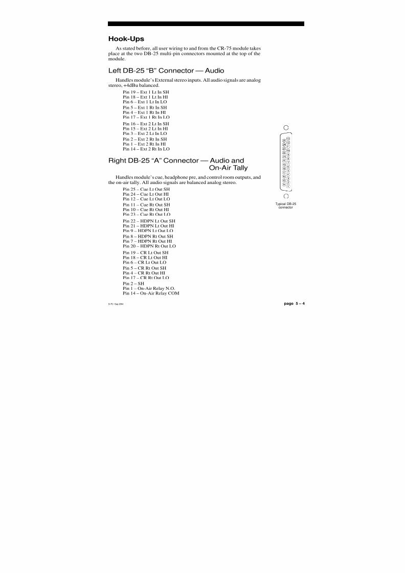
8/21/2019 D75 MANw_20121207.pdf
http://slidepdf.com/reader/full/d75-manw20121207pdf 50/128
page 5 – 4D-75 / Sep 2004
C O N T R O L R O O M M O D U L E
Hook-Ups
As stated before, all user wiring to and from the CR-75 module takesplace at the two DB-25 multi-pin connectors mounted at the top of themodule.
Left DB-25 “B” Connector — Audio
Handles module’s External stereo inputs. All audio signals are analogstereo, +4dBu balanced.
Pin 19 – Ext 1 Lt In SHPin 18 – Ext 1 Lt In HIPin 6 – Ext 1 Lt In LO
Pin 5 – Ext 1 Rt In SHPin 4 – Ext 1 Rt In HIPin 17 – Ext 1 Rt In LO
Pin 16 – Ext 2 Lt In SHPin 15 – Ext 2 Lt In HIPin 3 – Ext 2 Lt In LO
Pin 2 – Ext 2 Rt In SHPin 1 – Ext 2 Rt In HIPin 14 – Ext 2 Rt In LO
Right DB-25 “A” Connector — Audio and On-Air Tally
Handles module’s cue, headphone pre, and control room outputs, andthe on-air tally. All audio signals are balanced analog stereo.
Pin 25 – Cue Lt Out SHPin 24 – Cue Lt Out HIPin 12 – Cue Lt Out LO
Pin 11 – Cue Rt Out SHPin 10 – Cue Rt Out HIPin 23 – Cue Rt Out LO
Pin 22 – HDPN Lt Out SHPin 21 – HDPN Lt Out HIPin 9 – HDPN Lt Out LO
Pin 8 – HDPN Rt Out SHPin 7 – HDPN Rt Out HI
Pin 20 – HDPN Rt Out LOPin 19 – CR Lt Out SHPin 18 – CR Lt Out HIPin 6 – CR Lt Out LO
Pin 5 – CR Rt Out SHPin 4 – CR Rt Out HIPin 17 – CR Rt Out LO
Pin 2 – SHPin 1 – On-Air Relay N.O.Pin 14 – On-Air Relay COM
Typical DB-25connector

8/21/2019 D75 MANw_20121207.pdf
http://slidepdf.com/reader/full/d75-manw20121207pdf 51/128
page 5 – 5D-75 / Sep 2004
C O N T R O L R O O M M O D U L E
CR-75 Control Room Module DB Connector Pinouts
9
10
11
12
13
22
23
24
25
67
8
19
20
21
4
5
16
17
18
1
2
3
14
15
EXT2 RT IN HI
EXT2 RT IN SH
EXT2 LT IN LO
EXT1 RT IN HI
EXT1 RT IN SH
EXT1 LT IN LON/C
AUDIO GROUND
N/C
N/C
AUDIO GROUND
N/C
EXT2 RT IN LO
EXT2 LT IN HI
EXT2 LT IN SH
EXT1 RT IN LO
EXT1 LT IN HI
EXT1 LT IN SH
N/C
N/C
AUDIO GROUND
N/C
N/C
AUDIO GROUNDAUDIO GROUND
9
10
11
12
13
22
23
24
25
6
7
8
19
20
21
4
5
16
1718
1
2
3
14
15
I/O PORTS(Left DB-25 "B")
I/O PORTS(Right DB-25 "A")
ON-AIR RELAY N.O.
AUDIO GROUND
N/C
CR RT OUT HI
CR RT OUT SH
CR LT OUT LO
HDPN RT OUT HI
HDPN RT OUTSH
HDPN LT OUT LO
CUE RT OUT HI
CUE RT OUT SH
CUE LT OUT LO
ON-AIR RELAY COM
N/C
AUDIO GROUND
CR RT OUT LOCR LT OUT HI
CR LT OUT SH
HDPN RT OUT LO
HDPN LT OUT HI
HDPN LT OUT SH
CUE RT OUT LO
CUE LT OUT HI
CUE LT OUT SHAUDIO GROUND

8/21/2019 D75 MANw_20121207.pdf
http://slidepdf.com/reader/full/d75-manw20121207pdf 52/128
CONTROL
ROOM
R R
L
HDPN JACK
CUE OUT
R
L
R
L
HDPN OUT
LH
LH
L
R
R
L
CR OUT
L
H
LH
L
R
LH
L
H
L
RR
L
CUE SPKR
R
L
FROM CUE
MONITOR BUS
R
L
R
L
L
EV
EL
C
UE
HDPNINTERRUPT
FET SWMONO
CUEMUTE
FET SW
MONO
HD
P
N
L
EV
EL
L
INTERRUPT/MUTE
D-75 / Sep 2004
CR-75 Control Room Module - Signal Flow Diagram
CRINTERRUPT
FET SW
SW1 POS 1
F R O M
C O N S O L E
C O N T R O L L O G I C
CUE MUTE
ENABLE
CUE TO LTHDPN
CUE TO RTHDPN
CUE TOLT CR
CUE TORT CR
FROM CUE LOGIC LOGIC
FROM CR MUTE LOGIC
SW1 POS 3
SW1 POS 2
SW1 POS 4
SW1 POS 5
FRONT PANEL SWITCHES
LOGIC
LOGIC
EXT 1 EXT 2 PGM AUD AUX UTIL
SOURCE SELECT
AUTO S/S RST HOLD
TIMER
page
R
LL
H
LH
LH
LH
EXT 1
EXT 2
R
L
R
L S
O
U
R
C
E
S
E
L
E
C
T
F
E
T
S
WUTIL
AUX
AUD
PGM
F R O M C O
N S O L E M O N I T O R B U S S E S
MONO
RELAYLOW VOLTAGE
CONTACTS
L
EV
EL
CR
SW1 POS 6
AIR TALLY FOLLOW PGM DEFEAT

8/21/2019 D75 MANw_20121207.pdf
http://slidepdf.com/reader/full/d75-manw20121207pdf 53/128
page 6 – 1D-75 / Sep 2004
S T U D I O C O N T R O L M O D U L E
Studio Control Module
(SC-75)
Chapter Contents
Module Overview........................................................................ 6-2
Internal Programming Options ................................................. 6-3
External Talkback Mute/Dim ................................................................................... 6-3
Studio Dim .............................................................................................................. 6-3
Studio Pre Mute ...................................................................................................... 6-3
Hook-ups..................................................................................... 6-4
Left DB-25 “B” Connector — Audio ........................................................................ 6-4
Right DB-25 “A” Connector — Audio and Tally 2 ................................................... 6-4
DB Connector Pinout Drawing .................................................. 6-5
Studio Control Module Signal Flow .......................................... 6-6

8/21/2019 D75 MANw_20121207.pdf
http://slidepdf.com/reader/full/d75-manw20121207pdf 54/128
page 6 – 2D-75 / Sep 2004
S T U D I O C O N T R O L M O D U L E
Studio Control Module
(SC-75)
Module Overview
The SC-75 module is similar to the CR-75 module. The monitorsignal being sent to the studio output follows the source select switch-ing. This switching is identical to the control room module’s andincludes the console’s four stereo outputs (PGM, AUD, AUX, &UTIL), and two external stereo line level inputs brought directly intothe module.
The SC-75 module houses a studio monitor circuit, which followsthe source selection switches. This is a stereo output intended for aremote studio power amp/speaker system.
The SC-75 module has a talkback switch. When the talkback switchis pressed (it is momentary action), any inputs assigned to the talkback bus (see pages 3-3) will interrupt the regular monitor signal being sentto the studio output. The TALKBACK master level control sets thelevel of this talkback interrupt signal.
All user wiring to and from the SC-75 module takes place at theDB-25 multi-pin connectors mounted at the top of the module andlocated underneath the hinged meterbridge. There are two connectors:
the left one accepts the two stereo analog external inputs; the right onehandles the studio, studio pre, and mono talkback outputs, and the tally2 relay. All audio connections are stereo line level analog signals. Apinout drawing on page 6-5 shows all wiring connections at a glance.

8/21/2019 D75 MANw_20121207.pdf
http://slidepdf.com/reader/full/d75-manw20121207pdf 55/128
page 6 – 3D-75 / Sep 2004
S T U D I O C O N T R O L M O D U L E
Internal Programming Options
Internal programming for the studio control module is made via printedcircuit board (PCB) mounted dipswitch SW1 located on the top of the
module (beneath the DB-25 connectors). Note when a dipswitch positionis thrown to the right it is ON.
External Talkback Mute/Dim
There is an independent talkback output from the SC-75 module.A dipswitch setting makes this external talkback output MUTE wheneverthe studio is muted. You also have the option of making the output DIM(drop -20dB in level) instead of MUTE by a second dipswitch setting.
SW1 position 1 mutes external TB whenever Studio is muted*SW1 position 2 makes external TB DIM instead of MUTE
If position 2 is on the setting of position 1 is ignored.
Studio Dim
Input modules controlling studio microphones can be programmed toMUTE the studio whenever the module is turned on (i.e., it’s microphoneis live). If you wish, you can have the studio DIM (drop -20dB in level)instead of MUTE:
SW1 position 3 causes Studio to DIM instead of MUTE
Note the DIM functions do not affect talkback interrupts, which alwayscompletely replace the studio’s regular monitor feed with the console operator’sTB signal. Note also if a studio is muted, talkback cannot be heard. However, if a studio is programmed to DIM instead of MUTE, talkback audio could pre-sumably make it from the studio monitor speakers to the open studio mic.
Studio Pre Mute
The studio pre output can be made to mute whenever a moduleprogrammed for studio mute is turned on. When this is done it overridesthe studio dim function (that is, the main studio out will always mute, neverdim when studio pre mute is activated).
SW1 position 4 causes studio pre to mute
*factory default settings
D-75 / Dec 2008

8/21/2019 D75 MANw_20121207.pdf
http://slidepdf.com/reader/full/d75-manw20121207pdf 56/128
page 6 – 4D-75 / Sep 2004
S T U D I O C O N T R O L M O D U L E
Hook-Ups
As stated before, all user wiring to and from the SC-75 module takes placeat the two DB-25 multi-pin connectors mounted at the top of the module.
Left DB-25 “B” Connector — Audio
Handles module’s External stereo inputs. All audio signals are analogstereo, +4dBu balanced.
Pin 19 – Ext 1 Lt In SHPin 18 – Ext 1 Lt In HIPin 6 – Ext 1 Lt In LO
Pin 5 – Ext 1 Rt In SHPin 4 – Ext 1 Rt In HIPin 17 – Ext 1 Rt In LO
Pin 16 – Ext 2 Lt In SHPin 15 – Ext 2 Lt In HIPin 3 – Ext 2 Lt In LO
Pin 2 – Ext 2 Rt In SHPin 1 – Ext 2 Rt In HIPin 14 – Ext 2 Rt In LO
Right DB-25 “A” Connector — Audio and Tally 2
Handles module’s TB, studio pre, and studio outputs, and the tally 2. Allaudio signals are balanced analog stereo.
Pin 25 – TB Out SH
Pin 24 – TB Out HIPin 12 – TB Out LO
Pin 22 – ST Pre Lt Out SHPin 21 – ST Pre Lt Out HIPin 9 – ST Pre Lt Out LO
Pin 8 – ST Pre Rt Out SHPin 7 – ST Pre Rt Out HIPin 20 – ST Pre Rt Out LO
Pin 19 – ST Lt Out SHPin 18 – ST Lt Out HIPin 6 – ST Lt Out LO
Pin 5 – ST Rt Out SH
Pin 4 – ST Rt Out HIPin 17 – ST Rt Out LO
Pin 2 – SHPin 1 – Tally 2 Relay N.O.Pin 14 – Tally 2 Relay COM
Typical DB-25connector
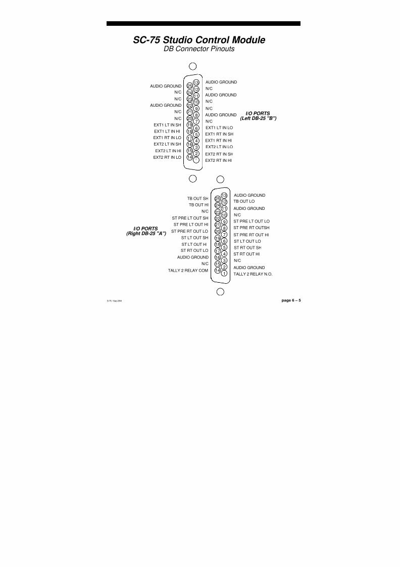
8/21/2019 D75 MANw_20121207.pdf
http://slidepdf.com/reader/full/d75-manw20121207pdf 57/128
page 6 – 5D-75 / Sep 2004
S T U D I O C O N T R O L M O D U L E
SC-75 Studio Control Module DB Connector Pinouts
9
10
11
12
13
22
23
24
25
67
8
19
20
21
4
5
16
17
18
1
2
3
14
15
EXT2 RT IN HI
EXT2 RT IN SH
EXT2 LT IN LO
EXT1 RT IN HI
EXT1 RT IN SH
EXT1 LT IN LON/C
AUDIO GROUND
N/C
N/C
AUDIO GROUND
N/C
EXT2 RT IN LO
EXT2 LT IN HI
EXT2 LT IN SH
EXT1 RT IN LO
EXT1 LT IN HI
EXT1 LT IN SH
N/C
N/C
AUDIO GROUND
N/C
N/C
AUDIO GROUNDAUDIO GROUND
9
10
11
12
13
22
23
24
25
6
7
8
19
20
21
4
5
16
1718
1
2
3
14
15
I/O PORTS(Left DB-25 "B")
I/O PORTS(Right DB-25 "A")
TALLY 2 RELAY N.O.
AUDIO GROUND
N/C
ST RT OUT HI
ST RT OUT SH
ST LT OUT LO
ST PRE RT OUT HI
ST PRE RT OUTSH
ST PRE LT OUT LO
N/C
AUDIO GROUND
TB OUT LO
TALLY 2 RELAY COM
N/C
AUDIO GROUND
ST RT OUT LOST LT OUT HI
ST LT OUT SH
ST PRE RT OUT LO
ST PRE LT OUT HI
ST PRE LT OUT SH
N/C
TB OUT HI
TB OUT SHAUDIO GROUND
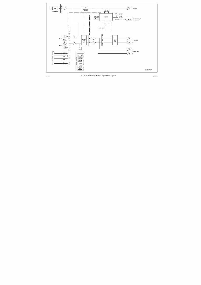
8/21/2019 D75 MANw_20121207.pdf
http://slidepdf.com/reader/full/d75-manw20121207pdf 58/128
STUDIO
LH
L
H
L
RR
L
ST OUT
S
T
TB OUTL
H
R
L
H
L
H
LH
L
H
EXT 1
EXT 2
R
L
R
L
S
O
U
R
C
E
S
E
L
E
C
T
F
E
T
S
WUTIL
AUX
AUD
PGM
UTIL
AUX
PGMAUD
EXT2
EXT1FRONT
PANEL
SWITCHES
LO
GIC
F R O M
C O N S O L E M O N I T O R B U S S E S
T
B
TB MONITOR
R
L
TB
SW
INTRPT
FET
SW
D-75/Sep 2004SC-75 Studio Control Module - Signal Flow Diagram
L
E
V
E
L
F R O M
D S P
L
E
V
E
L
L
TB
MUTE/DIM
FET SW
MUTE
FET
SW
pa
RELAY TALL Y 2
LOGIC
ST DIMSW1 POS 3
M
U
T
E
FROM CONSOLE
CONTROL LOGIC
LH
L
H
L
RR
L
ST PRE OUT
TB MUTESW1 POS 1
TB DIMSW1 POS 2
ST PRE MUTESW1 POS 4
DAC
LOW VOLTAGE
CONTACTS

8/21/2019 D75 MANw_20121207.pdf
http://slidepdf.com/reader/full/d75-manw20121207pdf 59/128
page 7 – 1D-75 / Sep 2004
S U P E R P H O N E I N P U T
Superphone Input
(SP-75; optional)
Chapter Contents
Module Overview........................................................................ 7-2
Caller Set-Ups ........................................................................................................ 7-2
Automatic Features ................................................................................................. 7-3
Inputs and Outputs ................................................................................................. 7-3
Internal Programming Options ................................................. 7-3
Cue Pre/Post .......................................................................................................... 7-3
Mutes ...................................................................................................................... 7-3
Timer Restart .......................................................................................................... 7-4
Tallies...................................................................................................................... 7-4
Cue Dropout............................................................................................................ 7-4
External Input.......................................................................................................... 7-4
Gain Trimpots ......................................................................................................... 7-4
Hook-ups..................................................................................... 7-5
Left DB-25 “B” Connector—Audio & Control .......................................................... 7-5
External START & STOP .................................................................................. 7-5
Right DB-25 “A” Connector—Audio........................................................................ 7-6
DB Connector Pinout Drawing .................................................. 7-7
Superphone Input Module Signal Flow .................................... 7-8

8/21/2019 D75 MANw_20121207.pdf
http://slidepdf.com/reader/full/d75-manw20121207pdf 60/128
page 7 – 2D-75 / Sep 2004
S U P E R P H O N E I N P U T
Superphone Input(SP-75; optional)
Module OverviewThe SP-75 input module is used for telephone call-ins, and can handle two
callers. Caller signals enter the module from your station hybrid. Each callerhas its own fader.
Output switches assign callers to any combination of the console’sfour outputs: PGM (program), AUD (audition), AUX (auxiliary), and/orUTIL (utility).
Two recessed front panel trimpots at the top of the module adjust the inputgain of the two CALLER signals.
Caller Set-UpsPre-air segment communication between the console operator (DJ) and
callers is via CUE buttons (2) which place the callers’ voices on the console’scue speakers (or control room speakers/operator’s headphone if the CR-75module’s cue interrupt function has been so programmed). These cue signalscan be programmed pre or post fader.
The DJ can assign his microphone input module to an unused outputbus—say UTIL—and the DJ then selects the UTIL input with the MXM FEEDSET switch. This sends a dedicated (digitally generated) version of the UTILbus signal to the SP-75 module’s hybrid output, where it is ultimately heardby the caller through his telephone. This mix minus source select method canalso be used to preplay a musical segment (or any other program content) forthe caller off-air. Take the IN-75 input module handling the desired music cutand assign it to an unused output bus; select the same bus as the caller’s mixminus source input and he will hear it off-air.
For convenient handling of call-ins, the console ships with the UTIL busassignments from IN-75 input modules made pre-fade and pre-on. That way,when you use UTIL as the caller MXM FEED source, the DJ mic, and anyother inputs you want the caller to hear, do not need to be turned on or fadedup for the callers to hear them, as long as those inputs are assigned to UTIL.If desired, the input pre-fade, pre-on feed to UTIL can be defeated (seepage 10-4), resulting in UTIL being fed post-fade, post-on for all inputs.Regardless of this setting, the caller audio to the UTIL bus is always post-fade,
post-on.The DJ microphone input module can also be assigned via dipswitch to the
console’s talkback (TB) bus. Any audio on the TB bus is heard by a caller whenthat caller’s cue button is pressed, if the Hybrid 1 Out and Hybrid 2 Outconnections are used.
The SP-75 also has an external mono audio input that can be selected viadipswitch to feed both caller outputs. One possible application is to feed theoutput of the DJ microphone QMP-4 channel both to the IN-75 input and theSP-75 external input. If the SP-75 dipswitch is set to enable the external inputthe DJ’s voice is always sent to the callers.
D-75 / Mar 2009

8/21/2019 D75 MANw_20121207.pdf
http://slidepdf.com/reader/full/d75-manw20121207pdf 61/128
page 7 – 3D-75 / Sep 2004
S U P E R P H O N E I N P U T
Automatic Features
The channel ON (red) and OFF (amber) switches are at the bottom of the module. These can be programmed (via internal PCB-mounteddipswitches) to activate control room and studio mutes, tallies, and timer
restart.Automatic cue dropout can also be programmed internally (page 7-4),
making it unnecessary to de-activate caller setup buttons before going live;simply pressing the module’s ON switch will automatically do this foryou.
Inputs and Outputs
All audio and control signals hook-ups are made via two multi-pinDB-25 connectors mounted at the top of the module and located under-neath the hinged meterbridge. The left connector handles the remote startand stop connections, the audio outputs to the caller hybrids, and the
following additional audio outputs: Composite Out – includes the DJ, callers, and any audio that feeds the
callers, except the TB bus - generally used for recording phone segmentsin advance of actual airplay.
Mics Out (also known as Composite Minus Callers) – includes all of the audio at the Composite Out except the callers.
Callers Only – includes only the callers, with no additional audio.
The right connector handles the caller inputs from the callers and theexternal input.
Internal Programming OptionsInternal programming is accomplished via printed circuit board (PCB)
mounted dipswitch SW1, located on the top of the module (beneath theDB-25 connectors). Note when a dipswitch position is thrown to the rightit is ON. The SP-75 PCB card contains PCB-mounted trimpots which maybe used to set the module’s output feed levels.
Cue Pre/Post
The module’s CUE signals (caller CUE buttons 1 & 2) can tap pre orpost fader.
SW1 position 2 activates pre-fader cue (default is post)
Mutes
When the SP-75 phone channel ON switch is pressed, it can activateconsole mute functions. Dipswitch SW1 determines which of the console’stwo mute lines will be activated:
SW1 position 6 mutes the control room and activates the air tally when the phone module is ON*SW1 position 5 mutes studio when the phone module is ON
*factory default settings
D-75 / Mar 2009
8/21/2019 D75 MANw_20121207.pdf
http://slidepdf.com/reader/full/d75-manw20121207pdf 62/128
page 7 – 4D-75 / Sep 2004
S U P E R P H O N E I N P U T
Timer Restart
When the module is turned ON, the console’s digital timer can beprogrammed to automatically reset to zero and begin counting up.
SW1 position 7 activates timer restart when the phone module’s
ON/START switch is pressed*
Tallies
Turning the module ON can activate a remote tally indicator. There are twotally control lines: on-air and tally 2.
SW1 position 6 activates the on-air tally control line (along with control room mute)
SW1 position 4 activates tally 2
Cue Dropout
CUE (i.e., caller CUE buttons 1 & 2) can be made to turn off when the
module’s ON/START switch is pressed. This is the factory default setting.
SW1 position 1 activates cue dropout
External Input
A mono input can be activated to feed the module’s outputs.
SW1 position 3 activates the external input (default is off)
Gain Trimpots
There are eight PCB-mounted trimpots, located on the SP-75 PCB. Theyare used as follows:
CR1 - sets Callers 1 In port input gainCR2 - sets Callers 2 In port input gainCR3 - sets the Ext In port input gainCR6 – sets the module’s “composite” output levelCR7 – sets the module’s “composite minus callers” (“mics out”)
output levelCR8 – sets the module’s “callers only” output levelCR9 – sets the module’s output level to Hybrid 1CR10 – sets the module’s output level to Hybrid 2
The first two trimpots are accessible through holes in the module faceplate.
*factory default settings

8/21/2019 D75 MANw_20121207.pdf
http://slidepdf.com/reader/full/d75-manw20121207pdf 63/128
page 7 – 5D-75 / Sep 2004
S U P E R P H O N E I N P U T
Hook-Ups
As stated before, all user wiring to and from the SP-75 modules takes placeat two multi-pin DB-25 connectors mounted on the top of the module.
Left DB-25 “B” Connector — Audio and Control
Handles module’s Composite, Mics, Callers, Hybrid 1, and Hybrid 2 audiooutputs, and the remote start and stop outputs. All audio signals are analogstereo, +4dBu balanced.
Pin 25 – Composite Out SHPin 24 – Composite Out HIPin 12 – Composite Out LO
Pin 11 – Mics Out SHPin 10 – Mics Out HIPin 23 – Mics Out LO
Pin 22 – Callers Out SHPin 21 – Callers Out HIPin 9 – Callers Out LO
Pin 8 – Hybrid 1 Out SHPin 7 – Hybrid 1 Out HIPin 20 – Hybrid 1 Out LO
Pin 19 – Hybrid 2 Out SHPin 18 – Hybrid 2 Out HIPin 6 – Hybrid 2 Out LO
Pin 5 – N/CPin 4 – Start/Stop ComPin 17 – Start/Stop Com
Pin 16 – StopPin 15 – StartPin 3 – Stop
Pin 2 – StartPin 1 – N/CPin 14 – N/C
To START and STOP Remote Source Machines Using Module ON/
OFF Switches
EXTERNAL START — Hook up the remote machine’s Start control pinsto the SP-75 module’s DB-25 connector control pins: for START wire to pins
2 (15) and 4 (17).EXTERNAL STOP — Hook up the remote machine’s Stop control pins
to the SP-75 module’s DB-25 connector control pins: for STOP wire to pins3 (16) and 4 (17).
Typical DB-25connector

8/21/2019 D75 MANw_20121207.pdf
http://slidepdf.com/reader/full/d75-manw20121207pdf 64/128
page 7 – 6D-75 / Sep 2004
S U P E R P H O N E I N P U T
When the module’s ON/START switch is pressed, an opto-isolatedclosure takes place between START/STOP COMMON and START;when the module’s OFF switch is pressed, an opto-isolated closure takesplace between START/STOP COMMON and STOP. These may be used
to control a remote tape machine for recording phone segments.Note, there are not two independent START and STOP outputs. There
are just two connections provided for each signal. Internally, pins 4 and 17are connected together, pins 2 and 15 are connected together, and pins 3and 16 are connected together.
Right DB-25 “A” Connector — Audio
Handles module’s mono External and Hybrid inputs. All audio signalsare analog stereo, +4dBu balanced.
Pin 25 – Ext In SH
Pin 24 – Ext In HIPin 12 – Ext In LO
Pin 22 – Caller 1 In SHPin 21 – Caller 1 In HIPin 9 – Caller 1 In LO
Pin 8 – Caller 2 In SHPin 7 – Caller 2 In HIPin 20 – Caller 2 In LO
Typical DB-25connector

8/21/2019 D75 MANw_20121207.pdf
http://slidepdf.com/reader/full/d75-manw20121207pdf 65/128
page 7 – 7D-75 / Sep 2004
S U P E R P H O N E I N P U T
SP-75 Superphone Input Module DB Connector Pinouts
9
10
11
12
13
22
23
24
25
6
7
8
1920
21
4
5
16
17
18
1
2
3
14
15
N/C
START
STOP
START/STOP COM
N/C
HYBRID 2 OUT LO
HYBRID 1 OUT HI
HYBRID 1 OUT SH
CALLERS OUT LO
MICS OUT HI
MICS OUT SH
COMPOSITE OUT LO
N/C
START
STOP
START/STOP COM
HYBRID 2 OUT HI
HYBRID 2 OUT SHHYBRID 1 OUT LO
CALLERS OUT HI
CALLERS OUT SH
MICS OUT LO
COMPOSITE OUT HI
COMPOSITE OUT SHAUDIO GROUND
9
10
11
12
13
22
23
24
25
6
7
8
19
20
21
4
5
16
17
18
1
2
3
14
15
I/O PORTS(Left DB-25 "B")
I/O PORTS(Right DB-25"A")
N/C
AUDIO GROUND
N/C
N/C
AUDIO GROUND
N/C
CALLER 2 IN HI
CALLER 2 IN SH
CALLER 1 IN LO
N/C
AUDIO GROUND
EXT IN LO
N/C
N/C
AUDIO GROUND
N/C
N/C
AUDIO GROUND
CALLER 2 IN LO
CALLER 1 IN HI
CALLER 1 IN SH
N/C
EXT IN HI
EXT IN SHAUDIO GROUND

8/21/2019 D75 MANw_20121207.pdf
http://slidepdf.com/reader/full/d75-manw20121207pdf 66/128
DIPSW 1
TALLY 2
TIMER RESTART
SUPERPHONE INPUT
STOP
START
FRONT PANEL SWITCHES
PGM AUD AUX UTIL CUE 1 CUE 2
TO HYBRID 1
LOGIC
T O C
O N S O L E
C O N T R O L B U S S E S
ON OFFMXM FEED SET
SUM OF
CALLERS
OUT
COMMON
SP-75 Superphone Module - Signal Flow DiagramD-75 / Sep 2004
LOGIC
ST MUTE
CR MUTE/ON AIR TALLY
TB MONITOR
TB TOCALLER
FET
SW
CUE
ASSIGN
FET SW
ANALOG TO
DIGITAL
CONVERTER
(ADC)
DATA
DATA
pa
CUE
TEL
TO HYBRID 2
LH
LH
COMPOSITE
OUT
LH
L
H
LH
MICS
TRIM
TRIM
TRIM
TRIM
TRIM
TRIM
CUE LOGIC
L
HHYBRID 2 IN
FROM
CALLERS
HYBRID 1 IN
TRIM
FADER
2
LH
TRIM
FADER
1
DIGITAL AUDIO
TEL MONITOR
TRIM
7
6
5
4
CUE PRE/POSTSW1 POS 2
EXT IN ONSW1 POS 3
CUE DROPOUTSW1 POS 1
LH
TRIM
EXT
ENABLE
FET SW
EXT IN

8/21/2019 D75 MANw_20121207.pdf
http://slidepdf.com/reader/full/d75-manw20121207pdf 67/128
page 8 – 1D-75 / Sep 2004
L I N E S E L E C T M O D U L E
Line Preselect Module
(LS-75; optional)
Chapter Contents
Module Overview ................................................................................. 8-2
Internal Programming Options .......................................................... 8-2
Hook-ups.............................................................................................. 8-3
Left DB-25 “B” Connector — Audio Inputs .........................................................................8-3
Left DB-25 “B” Connector — Audio Outputs ......................................................................8-3
Right DB-25 “A” Connector — Audio Inputs .......................................................................8-3
DB Connector Pinout Drawing........................................................... 8-5
Line Preselect Module Signal Flow ................................................... 8-6

8/21/2019 D75 MANw_20121207.pdf
http://slidepdf.com/reader/full/d75-manw20121207pdf 68/128
page 8 – 2D-75 / Sep 2004
L I N E S E L E C T M O D U L E
Line Preselect Module(LS-75; optional)
Module Overview
This optional module selects one of six stereo line sources and routesit to one stereo output, allowing you to expand the source capability of aninput channel or monitor module.
All audio input and output signals are made via two DB-25 multi-pinconnectors mounted at the top of the module and located underneath thehinged meterbridge.
Internal Programming OptionsThere are no internal programming options on the LS-75 module.
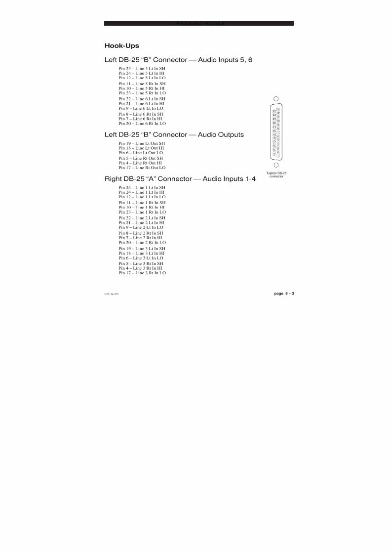
8/21/2019 D75 MANw_20121207.pdf
http://slidepdf.com/reader/full/d75-manw20121207pdf 69/128
page 8 – 3D-75 / Sep 2004
L I N E S E L E C T M O D U L E
Hook-Ups
Left DB-25 “B” Connector — Audio Inputs 5, 6Pin 25 – Line 5 Lt In SHPin 24 – Line 5 Lt In HIPin 12 – Line 5 Lt In LO
Pin 11 – Line 5 Rt In SHPin 10 – Line 5 Rt In HIPin 23 – Line 5 Rt In LO
Pin 22 – Line 6 Lt In SHPin 21 – Line 6 Lt In HIPin 9 – Line 6 Lt In LO
Pin 8 – Line 6 Rt In SH
Pin 7 – Line 6 Rt In HIPin 20 – Line 6 Rt In LO
Left DB-25 “B” Connector — Audio Outputs
Pin 19 – Line Lt Out SHPin 18 – Line Lt Out HIPin 6 – Line Lt Out LO
Pin 5 – Line Rt Out SHPin 4 – Line Rt Out HIPin 17 – Line Rt Out LO
Right DB-25 “A” Connector — Audio Inputs 1-4Pin 25 – Line 1 Lt In SHPin 24 – Line 1 Lt In HIPin 12 – Line 1 Lt In LO
Pin 11 – Line 1 Rt In SHPin 10 – Line 1 Rt In HIPin 23 – Line 1 Rt In LO
Pin 22 – Line 2 Lt In SHPin 21 – Line 2 Lt In HIPin 9 – Line 2 Lt In LO
Pin 8 – Line 2 Rt In SH
Pin 7 – Line 2 Rt In HIPin 20 – Line 2 Rt In LO
Pin 19 – Line 3 Lt In SHPin 18 – Line 3 Lt In HIPin 6 – Line 3 Lt In LO
Pin 5 – Line 3 Rt In SHPin 4 – Line 3 Rt In HIPin 17 – Line 3 Rt In LO
Typical DB-25connector
D-75 / Jan 2010

8/21/2019 D75 MANw_20121207.pdf
http://slidepdf.com/reader/full/d75-manw20121207pdf 70/128
page 8 – 4D-75 / Sep 2004
L I N E S E L E C T M O D U L E
Pin 16 – Line 4 Lt In SHPin 15 – Line 4 Lt In HIPin 3 – Line 4 Lt In LO
Pin 2 – Line 4 Rt In SHPin 1 – Line 4 Rt In HIPin 14 – Line 4 Rt In LO
Typical DB-25connector
D-75 / Jan 2010
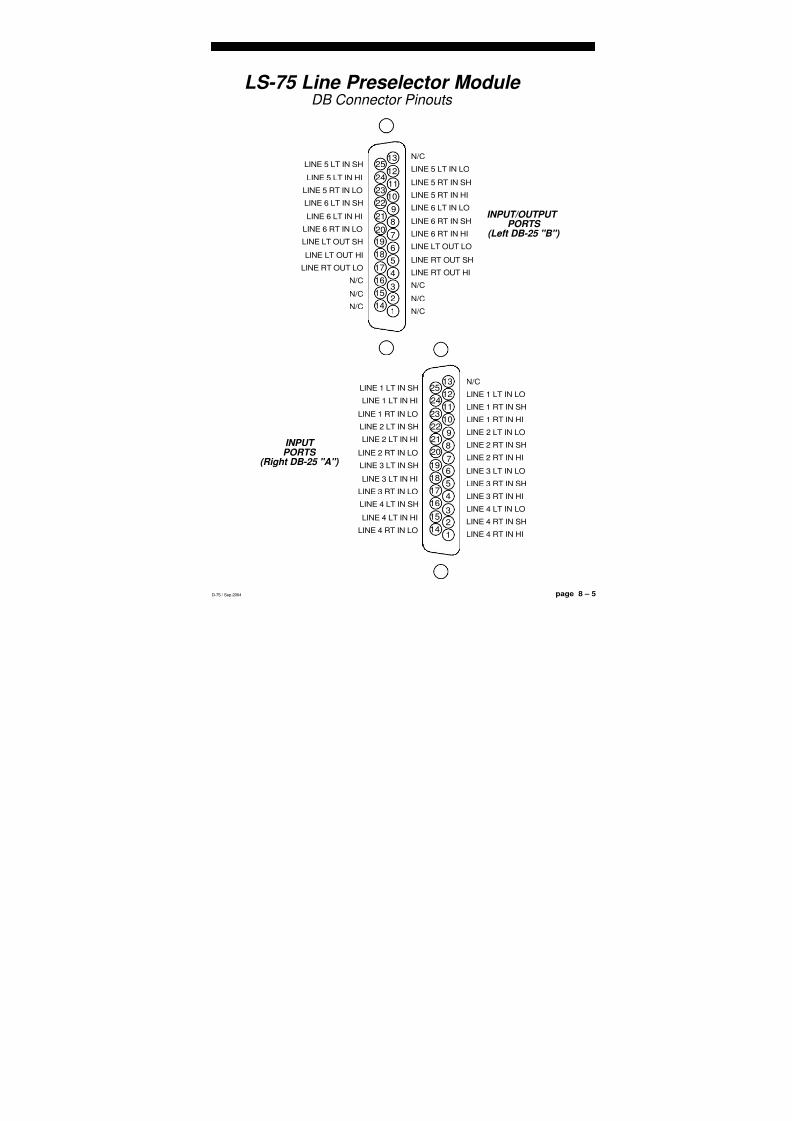
8/21/2019 D75 MANw_20121207.pdf
http://slidepdf.com/reader/full/d75-manw20121207pdf 71/128
page 8 – 5D-75 / Sep 2004
L I N E S E L E C T M O D U L E
LS-75 Line Preselector Module DB Connector Pinouts
9
10
11
12
13
22
23
24
25
6
7
8
19
20
21
4
5
16
17
18
1
2
3
14
15
N/C
N/C
N/C
LINE RT OUT HI
LINE RT OUT SH
LINE LT OUT LO
LINE 6 RT IN HI
LINE 6 RT IN SH
LINE 6 LT IN LO
LINE 5 RT IN HI
LINE 5 RT IN SH
LINE 5 LT IN LO
N/C
N/C
N/C
LINE RT OUT LO
LINE LT OUT HI
LINE LT OUT SH
LINE 6 RT IN LO
LINE 6 LT IN HI
LINE 6 LT IN SH
LINE 5 RT IN LO
LINE 5 LT IN HI
LINE 5 LT IN SHN/C
9
10
11
12
13
22
23
24
25
6
7
8
19
20
21
45
16
17
18
1
2
3
14
15
LINE 4 RT IN HI
LINE 4 RT IN SH
LINE 4 LT IN LO
LINE 3 RT IN HI
LINE 3 RT IN SH
LINE 3 LT IN LO
LINE 2 RT IN HI
LINE 2 RT IN SH
LINE 2 LT IN LO
LINE 1 RT IN HI
LINE 1 RT IN SH
LINE 1 LT IN LO
LINE 4 RT IN LO
LINE 4 LT IN HI
LINE 4 LT IN SH
LINE 3 RT IN LOLINE 3 LT IN HI
LINE 3 LT IN SH
LINE 2 RT IN LO
LINE 2 LT IN HI
LINE 2 LT IN SH
LINE 1 RT IN LO
LINE 1 LT IN HI
LINE 1 LT IN SHN/C
INPUT/OUTPUTPORTS
(Left DB-25 "B")
INPUT PORTS
(Right DB-25 "A")
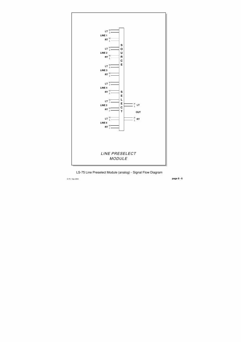
8/21/2019 D75 MANw_20121207.pdf
http://slidepdf.com/reader/full/d75-manw20121207pdf 72/128
LINE PRESELECT
MODULE
OUT
L
H
L
H
LT
RT
S
O
U
R
C
E
S
E
L
E
C
T
D-75 / Sep 2004
LS-75 Line Preselect Module (analog) - Signal Flow Diagram
page 8 - 6
LH
L
H
LINE 1
LT
RT
LH
L
H
LINE 2
LT
RT
LH
LH
LINE 3
LT
RT
LH
L
H
LINE 4
LT
RT
LH
L
H
LINE 5
LT
RT
LH
L
H
LINE 6
LT
RT

8/21/2019 D75 MANw_20121207.pdf
http://slidepdf.com/reader/full/d75-manw20121207pdf 73/128
page 9 – 1D-75 / Sep 2004
T A P E R E M O T E M O D U L E
Tape Remote Module
(TR-75; optional)
Chapter Contents
Module Overview ................................................................................. 9-2
DB Connector Pinout Drawings
START/STOP Function Control I/O ....................................................................................9-3
Full-Function Control I/O .................................................................................................... 9-4

8/21/2019 D75 MANw_20121207.pdf
http://slidepdf.com/reader/full/d75-manw20121207pdf 74/128
page 9 – 2D-75 / Sep 2004
T A P E R E M O T E M O D U L E
Tape Remote Module(TR-75; optional)
Module Overview
This optional module is available in two versions. TheSTART/STOP version offers three sets of START and STOPbuttons to provide start-stop control of three remote reel-to-reelmachines. The full function version provides RTZ, FF, REW,STOP, REC, and PLAY buttons for a single machine. LEDindicators in each switch function as tallyback indicators andare powered by the source machine. There are no internalconnections between the tape remote panel and the console’spower rails.

8/21/2019 D75 MANw_20121207.pdf
http://slidepdf.com/reader/full/d75-manw20121207pdf 75/128
page 9 – 3D-75 / Sep 2004
T A P E R E M O T E M O D U L E
9
10
11
12
13
22
23
2425
6
7
8
19
20
21
4
5
16
17
18
1
23
14
15
SW1 (START) LED+
SW1 (START) N.O.SW2 (STOP) LED+
SW2 (STOP) N.O
SW3 (START) LED+
SW3 (START) N.O.
SW4 (STOP) LED+
SW4 (STOP) N.O.
SW5 (START) LED+
SW5 (START) N.O.
SW6 (STOP) LED+
SW6 (STOP) N.O.
SW1 (START) LED-
SW1 (START) COMMON
SW2 (STOP) LED-
SW2 (STOP) COMMON
SW3 (START) LED-
SW3 (START) COMMON
SW4 (STOP) LED-
SW4 (STOP) COMMON
SW5 (START) LED-
SW5 (START) COMMON
SW6 (STOP) LED-SW6 (STOP) COMMON
N/C
I/O CONTRO PORTS (DB-25)
TR-75/SS Tape Remote Module DB Connector Pinouts
SW1
SW2
SW3
SW4
SW5
SW6

8/21/2019 D75 MANw_20121207.pdf
http://slidepdf.com/reader/full/d75-manw20121207pdf 76/128
page 9 – 4D-75 / Sep 2004
T A P E R E M O T E M O D U L E
9
10
11
12
13
22
23
2425
6
7
8
19
20
21
4
5
16
17
18
1
23
14
15
SW1 (RTZ) LED+
SW1 (RTZ) N.O.SW2 (FF) LED+
SW2 (FF) N.O
SW3 (REW) LED+
SW3 (REW) N.O.
SW4 (STOP) LED+
SW4 (STOP) N.O.
SW5 (REC) LED+
SW5 (REC) N.O.
SW6 (PLAY) LED+
SW6 (PLAY) N.O.
SW1 (RTZ) LED-
SW1 (RTZ) COMMON
SW2 (FF) LED-
SW2 (FF) COMMON
SW3 (REW) LED-
SW3 (REW) COMMON
SW4 (STOP) LED-
SW4 (STOP) COMMON
SW5 (REC) LED-
SW5 (REC) COMMON
SW6 (PLAY) LED-SW6 (PLAY) COMMON
N/C
I/O CONTROLPORTS (DB-25)
TR-75/FF Tape Remote Module DB Connector Pinouts
SW1
SW2
SW3
SW4
SW5
SW6
8/21/2019 D75 MANw_20121207.pdf
http://slidepdf.com/reader/full/d75-manw20121207pdf 77/128
page 10 – 1
M E T E R B R I D G E
D-75 / Sep 2004
Meterbridge
Chapter Contents
Overview ...................................................................................... 10-2
Digital Timer ................................................................................ 10-2
Console Clock ............................................................................. 10-3
Controls.................................................................................................................... 10-3
Setting the Time....................................................................................................... 10-3
Capacitor Backup .................................................................................................... 10-3
Operational Modes .................................................................................................. 10-3
24 Hour Mode ...................................................................................................... 10-3
External Sync....................................................................................................... 10-4
Dim ....................................................................................................................... 10-4
UTIL Pre-Fade / Pre-On Defeat ................................................... 10-4
B Source Logic Options ............................................................. 10-5
External AES Sync Input ............................................................ 10-5
D-75 / Nov 2009

8/21/2019 D75 MANw_20121207.pdf
http://slidepdf.com/reader/full/d75-manw20121207pdf 78/128
page 10 – 2
M E T E R B R I D G E
D-75 / Sep 2004
MeterbridgeOverview
The console’s meterbridge houses two pairs of left-right LED meters(Program and Switched; see “Output Module” Chapter 4), the digital timerdisplay, the cue speaker, and the console clock.
The meterbridge assembly hinges open for easy access (setting the clock).Simply swing the bridge up and back until it rests in a fully opened position.
Digital Timer
The console timer control buttons are located on the OM-75 OutputModule (see page 4-2).
The timer is provided with an AUTO-RESTART function so programmedinput modules can automatically reset the timer display to zero and start a newcount, allowing the announcer to easily track his own pace.
The START/STOP button halts the timer, holds the last count, and thenrestarts and accumulates the count when depressed again—perfect forcompiling tapes of desired duration.
RESET has a dual-mode capability:
- if you depress it while the timer is counting, the display will instantly reset
to zero and start a fresh count;- if the timer is already stopped, depressing this button will reset the timer
to zero, where it will hold until start is pressed.
HOLD button allows you to hold the display for a longer viewing duration,while still allowing the counter to continue in the background. Releasing thebutton will then display the current count.

8/21/2019 D75 MANw_20121207.pdf
http://slidepdf.com/reader/full/d75-manw20121207pdf 79/128
page 10 – 3
M E T E R B R I D G E
D-75 / Sep 2004
Console Clock
The Wheatstone digital clock is a six-digit time-of-day clock with LEDdisplay. The clock is designed with CMOS circuits and an on-board crystal-
controlled time base oscillator. Clock set controls may be accessed by openingthe meterbridge cover.
Controls
The clock is controlled by two switches mounted on the VU/clock/timerPCB assembly.
Setting the Time
The setting controls consist of two switches: MODE and SET. To set theclock, open the meterbridge cover:
1) The control switches (mounted on the main clock PCB assembly) arelabelled "M" and "S". "M" (Mode) is used to scroll from seconds to minutesto hours; "S" is used to Set the time. The procedure is to set the clock slightlyahead of the current time, hold the second count at "00" until the current timecatches up, and then release the count.
2) Press the MODE button until the hour digits blink. Depress the SET buttonuntil the desired hour is displayed.
3) Press the MODE button until the minute digits blink. Depress the SET buttonuntil the desired minute count is displayed.
4) Press the MODE button until the second digits blink. Depress and hold theSET button; the seconds display will hold at "00". When the current timecatches up to the display, release the SET button. The clock will start
counting. Hit the MODE button once more to place the clock into workingmode.
Capacitor Backup
With the meterbridge open note the super capacitor at C35. This supercapacitor is self charging. Note that the super capacitor does NOT light up theclock display; it powers the clock crystal to keep it from losing count (it willdo this for several days).
Operational Modes
The standard factory default clock configuration is crystal-controlled, 12hour mode, stand-alone operation. However, some operational features can bemodified using programmable dipswitch SW1 on the VU-75 PCB.
24 Hour Mode
The clock can be made to run in 24 hour mode.
SW1 position 1 enables 24 hour mode
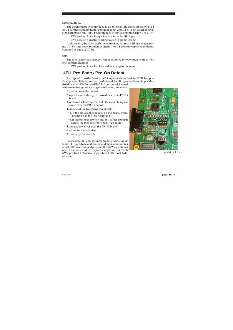
8/21/2019 D75 MANw_20121207.pdf
http://slidepdf.com/reader/full/d75-manw20121207pdf 80/128
page 10 – 4
M E T E R B R I D G E
D-75 / Sep 2004
External Sync
The clock can be synchronized to an external 1Hz signal (input on pin 1of CT8, referenced to digital common at pin 2 of CT8) or an external 60Hzsignal (input on pin 1 of CT9, referenced to digital common at pin 2 of CT9).
SW1 position 2 enables synchronization to the 1Hz input
SW1 position 3 enables synchronization to the 60Hz input
Additionally, the clock can be synchronized from an ESE master generat-ing TC-89 time code, brought in on pin 1 of CT10 and referenced to digitalcommon at pin 2 of CT10.
Dim
The timer and clock displays can be dimmed for operation in areas withlow ambient lighting.
SW1 position 4 enables clock and timer display dimming
UTIL Pre-Fade / Pre-On Defeat
As shipped from the factory, D-75 input modules feed the UTIL bus pre-fade, pre-on. This feature can be defeated for all input modules via position4 of dipswitch SW2 on the PR-75 circuit board, locatedin the meterbridge area, using the following procedure:
1. power down the console
2. open the meterbridge to provide access to PR-75 board
3. remove the 8 screws that hold the clear plexiglass cover over the PR-75 board
4. do one of the following (4a or 4b):
4a. if the dipswitch is loaded on the board, throw position 4 to the ON position, OR
4b. if there is no dipswitch present, solder a jumper across the two position 4 pads (see photo).
5. replace the cover over the PR-75 board
6. close the meterbridge
7. power up the console
Please note, it is not possible to have some inputsfeed UTIL pre-fade and pre-on and have other inputsfeed UTIL post-fade and post-on. With SW2 position 4open all inputs feed UTIL pre-fade, pre-on, and withSW2 position 4 closed all inputs feed UTIL post-fade,post-on.
D-75 / Sep 2007
position 4 pa

8/21/2019 D75 MANw_20121207.pdf
http://slidepdf.com/reader/full/d75-manw20121207pdf 81/128
page 10 – 5
M E T E R B R I D G E
D-75 / Sep 2004D-75 / Nov 2009
B Source Logic Options
As shipped from the factory the following IN-75 features only work, by default, whensource A is selected on a module: remote logic functions, with the exception of the B tally;
mutes and tallies; and timer restart. Dipswitch SW2 on the PR-75 module in themeterbridge provided a way to enable these features for B sources.
PR-75 SW2 position 1 (REM B) activates remote logic for B sources when ON
PR-75 SW2 position 2 (MUTE B) activates mutes and tallies for B sources when ON
PR-75 SW2 position 3 (TMR B) activates timer restart for B sources when ON
These settings are global in nature; each dipswitch setting affects all IN-75 modulesat the same time. In other words, if you need to, for example, do a CR mute from a B sourceon one module, then any other module that does a CR mute will also mute from the Bsource.
To make these settings, follow the directions shown on page 10-4 for UTIL Pre-Fade/ Pre-On Defeat, but substitute the dipswitch position required, as listed above.
In the case of mutes, tallies, and timer restart, note that the appropriate dipswitchsetting on the individual IN-75 module must also be set. That is, if you enable B timerrestart, a module must still have the timer restart dipswitch set for that module to do a timerrestart.
External AES Sync Input
The PR-75 board is provided with connector CT-12, a DB-9, to allow the console’ssample rate to by synchronized to an external AES Black signal (Word Clock is not supported). If a valid AES sync signal is connected, the console automatically synchro-nizes to this signal, and if the signal disappears or becomes invalid the console automati-
cally switches back to the internal sample rate clock. The internal sample rate should beset to the same frequency as the external sync to avoid drastic sample rate changes if theexternal sync is lost.
N/C
N/C
N/C
AES SYNC IN LO
ANALOG GROUND
N/C
N/C
AES SYNC IN SH
AES SYNC IN HI
59
4
3
2
1
8
7
6
CT-12
Female DB-9
8/21/2019 D75 MANw_20121207.pdf
http://slidepdf.com/reader/full/d75-manw20121207pdf 82/128
page 11 – 1D-75 / Sep 2004
S C H E M A T I C D R A W I N G S
Schematics and Load SheetsChapter Contents
Quad Mic Preamp (QMP-4)
schematic ................................................................................................................. 11-2
load sheet ................................................................................................................ 11-3
Input Module (IN-75)
schematic ................................................................................................................. 11-4
load sheet ................................................................................................................ 11-6
A to D Converter (ADC-75)
schematic ................................................................................................................. 11-7
load sheet ................................................................................................................ 11-8
Sample Rate Converter (SRC-75)
schematic ................................................................................................................. 11-9
load sheet ............................................................................................................... 11-10
Output Module (OM-75)schematic ................................................................................................................ 11-11
load sheet ............................................................................................................... 11-14
Control Room Module (CR-75)
schematic ................................................................................................................ 11-15
load sheet ............................................................................................................... 11-19
Studio Control Module (SC-75)
schematic ................................................................................................................ 11-20
load sheet ............................................................................................................... 11-24
Superphone (SP-75)
schematic ................................................................................................................ 11-25
load sheet ............................................................................................................... 11-28
Line Select (LS-75)
schematic ................................................................................................................ 11-29
load sheet ............................................................................................................... 11-30
Tape Remote (TR-75)
schematic ................................................................................................................ 11-31
load sheet ............................................................................................................... 11-32
VU Card (VU-75)
schematic ................................................................................................................ 11-33
load sheet ............................................................................................................... 11-35
Mother Board—Right (MBR-75)
schematic ................................................................................................................ 11-36load sheet ............................................................................................................... 11-38
Mother Board—Extender (MBE-75)
schematic ................................................................................................................ 11-39
load sheet ............................................................................................................... 11-41
Processor Board (PR-75)
load sheet ............................................................................................................... 11-42
Power Supply (SPS-100)
schematic ................................................................................................................ 11-43
load sheet ............................................................................................................... 11-44
D-75 / Nov 2007

8/21/2019 D75 MANw_20121207.pdf
http://slidepdf.com/reader/full/d75-manw20121207pdf 83/128
V+
V-
C15
0.1uF
C21
0.1uF
C3
0.1uF
C8
0.1uF AGND
C25
0.1u
C
0
D-75/Sep 2004QMP-4 Quad Mic Preamp Schematic -
8 7 6 5 4
45678
A
B
C
D
C4
0.001uF
AGND
C9
0.001uF
AGND
10.0K
R5
10.0K
R13
C10 10uF
C1 10uF
AGND
330pF
C5
AGND
AGND AGND
10
R12
22uF C6
AGND
C5V1Z2
5.1V
Z4C5V15.1V
C5V1Z3
5.1VC5V1
Z1
5.1V
V+
V-
V + V
-
-10dBu -2dBu
1
2
3
4
5 6
7
8
U2
-SSM2017
V -
V +
+
L1L2
HI
LO
AGND
SH
3
2
1
1 K
C R 1
5532
3
2
1
8
4
U1
+
-
V +
V -
5532
6
5 U1
+
-
C7 33pF
13.3KR8
4.99KR1
10R2
AGND
C2 33pF
4.99KR3
4.99KR4
C16
0.001uF
AGND
C22
0.001uF
AGND
10.0K
R19
10.0K
R27
C23 10uF
10uFC13
AGND
C17
330pF
AGND
AGND AGND
10
R26
C1822uF
AGND
Z6C5V15.1V
C5V1Z8
5.1V
Z7C5V15.1V
Z5C5V15.1V
V+
V-
V + V
-
-10dBu -2dBu
U4
8
7
65
4
3
2
1
-SSM2017
V -
V +
+
L3L4
HI
LO
AGND
SH
1 K
1
2
3
C R 2
5532U3
4
8
1
2
3+
-
V +
V -
5532U3
5
6
+
-
C20 33pF
13.3KR22
4.99KR15
10R16
AGND
C14 33pF
4.99KR17
4.99KR18
C26
0.001uF
AGND
C33
0.001uF
AGND
10.0K
R35
10.0K
R42
C34 10uF
C27 10uF
AGND
C28
330pF
AGND
AGND AGND
10
R41
C3022uF
AGND
Z10C5V15.1V
C5V1Z12
5.1V
Z11C5V15.1V
C5V1Z9
5.1V
V+
V-
V + V
-
-10dBu -2dBu
U6
1
2
3
4
5 6
7
8
-SSM2017
V -
V +
+
L5L6
HI
LO
AGND
SH
3
2
1
1 K
C R 3
5532U53
2
1
8
4
+
-
V +
V -
5532U5
6
5+
-
C31 33pF
13.3KR37
4.99KR31
10R32
AGND
C24 33pF
4.99KR33
4.99KR34
0.001uF
C39
AGND
0.001uF
C45
AGND
10.0K
R50
10.0K
R56
10uFC46
10uFC40
AGND
330pF
C41
AGND
AGND AGND
10
R55
22uF C42
AGND
Z14C5V15.1V
C5V1Z16
5.1V
Z15C5V15.1V
C5V1Z13
5.1V
V+
V-
V + V
-
-10dBu -2dBu
U8
8
7
65
4
3
2
1
-SSM2017
V -
V +
+
L7L8
HI
LO
AGND
SH
1 K
1
2
3
C R 4
5532U7
4
8
1
2
3+
-
V +
V -
5532U7
5
6
+
-
33pFC43
13.3KR51
4.99KR46
10R47
AGND
33pFC37
4.99KR48
4.99KR49
C T 1
1 2 3
C T 2
1 2 3
C T 5
1 2 3
C T 6 1 2 3
4.99K
R14
4.99K
R7
1 . 3
0 K
R 6SW1
714
C11
10uF
AGND
4.99K
R28
4.99K
R21
1 . 3
0 K
R 2 0SW1
12 5
C19
10uF
AGND
4.99K
R36
4.99K
R30
1 . 3
0 K
R 2 9SW1
310
C29
10uF
AGND
4.99K
R45
4.99K
R44
1 . 3
0 K
R 4 3SW1
18
10uF
C36
AGND
MIC1INHI
MIC1INLO
MIC2INLO
MIC2INHI
MIC3INHI
MIC3INLO
MIC4INLO
MIC4INHI
PH1
+PhV
PH2
+PhV
PH3
+PhV
PH4
+PhV
-50dBu BAL
-50dBu BAL
-50dBu BAL
-50dBu BAL
MIC 1
MIC 2
MIC 3
MIC4
MIC 1GAIN
TRIM
MIC 2GAIN
TRIM
MIC 3GAIN
TRIM
MIC 4GAIN
TRIM
NOT INSTALLED
NOT INSTALLED
NOT INSTALLED
NOT INSTALLED

8/21/2019 D75 MANw_20121207.pdf
http://slidepdf.com/reader/full/d75-manw20121207pdf 84/128
page 11 – 2D-75 / Sep 2004
S C H E M A T I C D R A W I N G S
QMP-4 Quad Mic Preamp - Load Sheet
page 11 – 3

8/21/2019 D75 MANw_20121207.pdf
http://slidepdf.com/reader/full/d75-manw20121207pdf 85/128

8/21/2019 D75 MANw_20121207.pdf
http://slidepdf.com/reader/full/d75-manw20121207pdf 86/128
600 Industrial Drive New Bern, NC 28562
1 2
3 4
5 6
7 8
9 10
11 12
13 14
15 16
17 18
19 20
21 22
23 24
25 2627 28
29 30
31 32
33 34
35 36
37 38
39 40
41 42
43 44
45 46
47 48
49 50
51 52
53 54
55 56
57 58
59 60
61 62
CT2
D-75/Nov 2004 page 11 - 5
IN-75 Input Module Schematic - Sheet 2 of 2
2 OF 2
16S1003
IN-75A PCB
IN-75
W# 700801
11-4-04
A
SA
SA
SA
- Sergey Averin -
APPROVALS DATE
REV SIZE
SHEET SCALE
DWG. NO.
CONTRACT NO.
DRAWN
CHECKED
ISSUEDFSCM NO.
B
2
2 1
1
B
AA
B
3635
3433
3231
3029
2827
2625
2423
2221
2019
1817
1615
1413
1211
109
87
65
43
21
CT1
DB1
DB2
DB3
DB4
DB5
DB6
DB14
DB15
DB16
DB17
DB18
DB19
BUF_D[3]
BUF_D[1]
BUF_D[6]
BUF_D[4]
BUF_D[0]
BUF_D[5]
BUF_D[15]
BUF_D[9]BUF_D[8]
BUF_D[14]
V+in
BUF_D[12]
BUF_D[10]
+DIGin
V-in
BUF_D[11]
BUF_D[13]
BUF_D[7]
BUF_D[2]
GND
MDL_A[0] MDL_A[1]
GND
AGND
MCLK_I
AGND
LR_I
AGND
DBS_S
GND
DB_VCC
GND
MDL_A[4]MDL_A[3]
MDL_A[2]
+PHin
BUF_A[4]
BUF_A[2]
BUF_A[3]
BUF_A[1]
BUF_A[5]
MCLK
SCLK
GNDGND
LR
SDATA
AGND AGND
GND GND
GND
VCC
GND
V-
V+
AGND
PHANT
SDATA_I
SCLK_I
AGND AGND
MDL_ID[0] MDL_ID[1]
PHONE_SD
N/C
N/C
N/C
N/C
N/C
N/C
EDGE CONNECTOR BUSS CHART

8/21/2019 D75 MANw_20121207.pdf
http://slidepdf.com/reader/full/d75-manw20121207pdf 87/128
IN-75 Input Module - Load SheetD-75 / Sep 2004

8/21/2019 D75 MANw_20121207.pdf
http://slidepdf.com/reader/full/d75-manw20121207pdf 88/128

8/21/2019 D75 MANw_20121207.pdf
http://slidepdf.com/reader/full/d75-manw20121207pdf 89/128
page 11 – 3D-75 / Sep 2004
S C H E M A T I C D R A W I N G S
ADC-75 A to D Converter - Load Sheet
page 11 – 8D-75 / Mar 2010

8/21/2019 D75 MANw_20121207.pdf
http://slidepdf.com/reader/full/d75-manw20121207pdf 90/128
GND
14
16
15
5
4
3
2
1
17
6
18
19
D-75 / Sep 2010
B
C
A
D
5 4678
5 4678
220
R13
220
R9
220
R12
220
R14
GND
GND
U1
7
6
5
4
12
1
2
3
9
10
11
15
14 13
AM26C32
OUTA
OUTB
OUTC
OUTD
A-
B+
B-
C+
C-
D+
D-
EN ___
A+
EN
220
R10
220
R11
T1
3
1
4
6
T2
3
1
4
6
0.1uF C4
0.1uF C3
C10.01uF
U5
15
1
2
3
4
5
6
714
13 12
11
10
9
74ACT157
1Y
2Y
3Y
4Y
1B
2A
2B
3A
3B
4A
4B __ A/B __
1A
G
SW11
SW21
CT21 2
3 4
5 6
7 8
9 10
11 12
13 14
15 16
17 18
19 20
21 22
23 24
25 26
27 28
29 30
31 32
33 34
35 36
DB1
DB2
DB3
DB4
DB5
DB6
MDL_ID[0]
68R7
GNDGND
+3.3V
L1
CS8416
28
27
26
25
24
23
22
21
20
19
18
17
16
15
14
13
12
11
10
9 8
7
6
5
4
3
2
1U3
______
FILT
RXN
DGND AGND
RXP0
RXP1
RXP2
RXP3
VA VD VL
RST
OMCK
RMCK
SDOUT
OSCLK
OLRCK
RXSEL1
RXSEL0
TXSEL1TXSEL0
NV/RERR
AUDIO
96KHZ
RCBL
U
C
TX
____
GNDGND
GND
+3.3V
3.92K R15 10C14
1nFC16
GND GND
+3.3V+3.3V
40.2K
R1
GND
GND
10C15
4.7uF
C10
+3.3V +3.3V
GND
C20.01uF
10.0KR16
Y1
24.576MHZ
E/ D O UT _
+3.3V
0.1uF
C11
4.99K
R6
4.99K
R5
4.99K
R4
4.99K
R2
4.99K
R3
1.00K
R17
40.2K
R18
DBS_S
DB_VCC DB_VCC
A_IN_HI
B_IN_LO
A_IN_LO
B_IN_HI
AGND
DBS_S D
GND
GND
V+
AGND
SDATA_I
SCLK_I
SDATA_I
LR_I
SCLK_I
RESET_I~
FOR 75 OHM
FOR 75 OHM
READY
COUGH
TB SWITCH
A/B LOGIC FOLLOW
DIGITAL COMMON
+5V
START
STOP
ON TALLY
MACHINE COMMON
REMOTE OFFREMOTE ON
- 1,0- H,H- L,H- H,L- L,L (*)
MDL ID BITNO PCB
SRCSLADC
MMADC
EDGE CONNECTOR BUSS CHA

8/21/2019 D75 MANw_20121207.pdf
http://slidepdf.com/reader/full/d75-manw20121207pdf 91/128
page 11 – 4D-75 / Sep 2004
S C H E M A T I C D R A W I N G S
SRC-75 Sample Rate Converter - Load Sheet
page 11 – 10D-75 / Sep 2010

8/21/2019 D75 MANw_20121207.pdf
http://slidepdf.com/reader/full/d75-manw20121207pdf 92/128

8/21/2019 D75 MANw_20121207.pdf
http://slidepdf.com/reader/full/d75-manw20121207pdf 93/128

8/21/2019 D75 MANw_20121207.pdf
http://slidepdf.com/reader/full/d75-manw20121207pdf 94/128
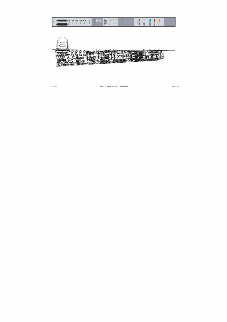
8/21/2019 D75 MANw_20121207.pdf
http://slidepdf.com/reader/full/d75-manw20121207pdf 95/128
pageOM-75 Output Module - Load SheetD-75 / Oct 2010

8/21/2019 D75 MANw_20121207.pdf
http://slidepdf.com/reader/full/d75-manw20121207pdf 96/128

8/21/2019 D75 MANw_20121207.pdf
http://slidepdf.com/reader/full/d75-manw20121207pdf 97/128

8/21/2019 D75 MANw_20121207.pdf
http://slidepdf.com/reader/full/d75-manw20121207pdf 98/128

8/21/2019 D75 MANw_20121207.pdf
http://slidepdf.com/reader/full/d75-manw20121207pdf 99/128
600 Industrial Drive New Bern, NC 28562
MM
WWP
MM/WWP 6-24-10
W# 700805
CR-75
CR-75D PCB
16S100x
4 OF 4
D
D-75 / July 2010 page 11 - 18
A
B B
A
APPROVALS
BFSCM NO.
ISSUED
CHECKED
DRAWN
CONTRACT NO.
DWG. NO.
SCALE SHEET
SIZE REV
DATE
- SA UR US - Sergey Averin -
12
2 1
3635
3433
3231
3029
2827
2625
2423
2221
2019
1817
1615
1413
1211
109
87
65
43
21
CT3
3635
3433
3231
3029
2827
2625
2423
2221
2019
1817
1615
1413
1211
109
87
65
43
21
CT4
CUE_PHN_GND
25
24
23
22
21
20
19
18
17
16
15
14
13
12
11
10
9
8
7
6
5
4
3
2
1
CT1
DB1
DB2
DB4
DB5
DB6
DB8
DB11
DB14
DB16
DB17
DB18
DB19
DB22
DB25
DB13
DB10
DB12
DB23
DB24
DB20
DB21
DB7
DB9
2625
2423
2221
2019
1817
1615
1413
1211
109
87
65
43
21
CT2
DB2
DB3
DB5
DB8
DB11
DB15
DB16
DB19
DB22
DB25
DB13
DB1 DB14
DB4
DB6
DB17
DB18
BUF_D[3]
BUF_D[1]
BUF_D[6]
BUF_D[4]
BUF_D[0]
BUF_D[5]
BUF_D[15]
BUF_D[9]BUF_D[8]
BUF_D[14]
V+in
BUF_D[12]
BUF_D[10]
+DIGin
V-in
BUF_D[11]
BUF_D[13]
BUF_D[7]
BUF_D[2]
GND
MDL_A[0] MDL_A[1]
GND
AGND
GND
MDL_A[4]MDL_A[3]
MDL_A[2]
BUF_A[4]
BUF_A[2]
BUF_A[3]
BUF_A[1]
BUF_A[5]
MCLK
SCLK
GNDGND
LR
SDATA23
AGND AGND
GND GND
AGND AGND
SDATA_CR
MN_SCKMN_MOMI
AGND
AGND
AGND
AGND
AGND
AGND
CUE_RT_HI
CUE_LT_LO
CUE_RT_LO
CUE_LT_HI
AGND
AGND
AGND
AGND
HDPN_RT_HI
HDPN_LT_LO
HDPN_RT_LO
HDPN_LT_HI
CR_RT_HI
CR_LT_LO
CR_RT_LO
CR_LT_HI
TALLY_NOTALLY_C
AGND
AGND
AGND
AGND
AGND
AGND
AGND
AGND
AGND
EXT2LT_LO
EXT2LT_HI
EXT2RT_HI EXT2RT_LO
EXT1LT_HI
EXT1RT_LO
EXT1LT_LO
EXT1RT_HI
SDATA_CUE
CUE_OUT
PHN_OUT_LT PHN_OUT_RT
AGND
EDGE CONNECTORS BUSS CHART
N/C
N/C
N/C
N/C
N/C
N/C
N/C (+PHin)
To Left DB-25 CONNECTOR Right DB-25 CONNECTOR

8/21/2019 D75 MANw_20121207.pdf
http://slidepdf.com/reader/full/d75-manw20121207pdf 100/128
pageCR-75 Control Room Module - Load SheetD-75 / July 2010

8/21/2019 D75 MANw_20121207.pdf
http://slidepdf.com/reader/full/d75-manw20121207pdf 101/128

8/21/2019 D75 MANw_20121207.pdf
http://slidepdf.com/reader/full/d75-manw20121207pdf 102/128

8/21/2019 D75 MANw_20121207.pdf
http://slidepdf.com/reader/full/d75-manw20121207pdf 103/128
D-75 / July 2010
B
C
A
D
5 4678
5 4678
AGND
74VHC4053
6 12
14
11
13
U26S
INH
X-Y
Y
X
74VHC4053
5
9
4 3
6
U26S
INH
X-Y
Y
X
74VHC4053
2
10
15 1
6
U26S
INH
X-Y
Y
X
GND
74VHC4053
13
11
14
126
U27S
INH
X-Y
Y
X
74VHC4053
6
34
9
5
U27S
INH
X-Y
Y
X
74VHC4053
6
115
10
2
U27S
INH
X-Y
Y
X
74VHC4053
13
11
14
126
U28S
INH
X-Y
Y
X
74VHC4053
6
34
9
5
U28S
INH
X-Y
Y
X
74VHC4053
6
115
10
2
U28S
INH
X-Y
Y
X
74VHC4053
6 12
14
11
13
U29S
INH
X-Y
Y
X
74VHC4053
5
9
4 3
6
U29S
INH
X-Y
Y
X
74VHC4053
2
10
15 1
6
U29S
INH
X-Y
Y
X
74VHC4053
13
11
14
126
U30S
INH
X-Y
Y
X
74VHC4053
6
34
9
5
U30S
INH
X-Y
Y
X
74VHC4053
6
115
10
2
U30S
INH
X-Y
Y
X
V+
V-
OP275
6
5
7U20
OP275
4
8
2
3
1U20
2.32K R87
33pF C101
AGND
AGND
2.32K R60
33pF C90
-22dBu
-22dBu
V+
V-
OP275 7
5
6
U9
OP275 1
3
2
8
4
U9
10.0K R47
33pF C68
AGND
AGND
10.0K R36
33pF C51
-2dBu
-2dBu
V+
V-
OP275
6
5
7U31
OP275
4
8
2
3
1U31
10.0K R124
33pF C133
AGND
AGND
20.0K R98
33pF C114 -2dBu
100uF C70
100uF C71
100uF C72
100uF C73
100uF C74
10.0KR68
10.0KR70
10.0KR72
10.0KR74
88.7KR67
4.99KR73
88.7KR69
4.99KR71
10.0KR76
88.7KR75
-8dBu
-8dBu
-2dBu
-2dBu
-8dBu AGND
AGND
AGND
AGND
AGND
STPRE_LT
STPRE_RT
STOUTLT
STOUTRT
TBOUT
TBDCAOUT
ST_LT
ST_RT
STDCAOUTLT
STDCAOUTRT

8/21/2019 D75 MANw_20121207.pdf
http://slidepdf.com/reader/full/d75-manw20121207pdf 104/128
600 Industrial Drive New Bern, NC 28562
page 11 - 23D-75 / July 2010
6-23-10
W# 700806
SC-75
SC-75C PCB
16S100x
4 OF 4
C
WWP
MM
WWP
A
B B
A
APPROVALS
BFSCM NO.
ISSUED
CHECKED
DRAWN
CONTRACT NO.
DWG. NO.
SCALE SHEET
SIZE REV
DATE
- SA UR US - Sergey Averin -
12
2 1
CT4
3635
3433
3231
3029
2827
2625
2423
2221
2019
1817
1615
1413
1211
109
87
65
43
21
CT51 2
3 4
5 6
7 8
9 10
11 12
13 14
15 16
17 18
19 20
21 22
23 24
25 26
27 28
29 30
31 32
33 34
35 36
CT1
1
6
18
7
19
8
20
9
21
10
22
2
11
23
12
24
13
25
3
4
5
14
15
16
17
DB1
DB2
DB4
DB5
DB6
DB8
DB11
DB14
DB16
DB17
DB18
DB19
DB22
DB25
DB13
DB12
DB24
DB20
DB21
DB7
DB9
CT2
1
10
11 12
13 14
15 16
17 18
19
2
20
21 22
23 24
25 26
3 4
5 6
7 8
9
DB2
DB3
DB5
DB8
DB11
DB15
DB16
DB19
DB22
DB25
DB13
DB1 DB14
DB4
DB6
DB17
DB18
BUF_D[3]
BUF_D[1]
BUF_D[6]
BUF_D[4]
BUF_D[0]
BUF_D[5]
BUF_D[15]
BUF_D[9]BUF_D[8]
BUF_D[14]
V+in
BUF_D[12]
BUF_D[10]
+DIGin
V-in
BUF_D[11]
BUF_D[13]
BUF_D[7]
BUF_D[2]
GND
MDL_A[0] MDL_A[1]
GND
AGND
GND
MDL_A[4]MDL_A[3]
MDL_A[2]
BUF_A[4]
BUF_A[2]
BUF_A[3]
BUF_A[1]
BUF_A[5]
MCLK
SCLK
GNDGND
LR
SDATA24
AGND AGND
GND GND
AGND AGND
SDATA_ST
MN_SCKMN_MOMI
AGND
AGND
AGND
AGND
AGND
TB_LOTB_HI
AGND
AGND
AGND
AGND
STPRE_RT_HI
STPRE_LT_LO
STPRE_RT_LO
STPRE_LT_HI
ST_RT_HI
ST_LT_LO
ST_RT_LO
ST_LT_HI
TALLY_NOTALLY_C
AGND
AGND
AGND
AGND
AGND
AGND
AGND
AGND
AGND
EXT2LT_LO
EXT2LT_HI
EXT2RT_HI EXT2RT_LO
EXT1LT_HI
EXT1RT_LO
EXT1LT_LO
EXT1RT_HI
SDATA_TB
AGND
EDGE CONNECTORS BUSS CHART
N/C
N/C
N/C
N/C
N/C
N/C
N/C (+PHin)
To Left DB-25 CONNECTOR Right DB-25 CONNECTOR

8/21/2019 D75 MANw_20121207.pdf
http://slidepdf.com/reader/full/d75-manw20121207pdf 105/128
pageSC-75 Studio Control Module - Load SheetD-75 / July 2010

8/21/2019 D75 MANw_20121207.pdf
http://slidepdf.com/reader/full/d75-manw20121207pdf 106/128

8/21/2019 D75 MANw_20121207.pdf
http://slidepdf.com/reader/full/d75-manw20121207pdf 107/128
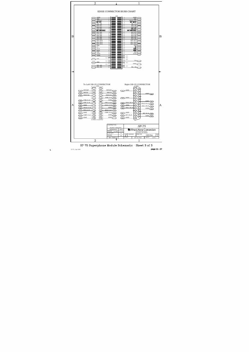
8/21/2019 D75 MANw_20121207.pdf
http://slidepdf.com/reader/full/d75-manw20121207pdf 108/128
600 Industrial Drive New Bern, NC 28562
CT4
6261
6059
5857
5655
5453
5251
5049
4847
4645
4443
4241
4039
3837
3635
3433
3231
3029
28272625
2423
2221
2019
1817
1615
1413
1211
109
87
65
43
21
SA/WWP 4-25-08
W# 700814
SP-75
SP-75C PCB
16S10xx
3 OF 3
C
D-75 / Apr 2008 page 11 - 27
A
B B
A
APPROVALS
BFSCM NO.
ISSUED
CHECKED
DRAWN
CONTRACT NO.
DWG. NO.
SCALE SHEET
SIZE REV
DATE
- SA UR US - Sergey Averin -
SA
SA
12
2 1
CT1
1
6
18
7
19
8
20
9
21
10
22
2
11
23
12
24
13
25
3
4
5
14
15
16
17
DB2
DB5
DB8
DB11
DB16
DB19
DB22
DB25
DB13
DB12
DB24
DB20DB7
CT2
1
10
11 12
13 14
15 16
17 18
19
2
20
21 22
23 24
25 26
3 4
5 6
7 8
9
DB2
DB3
DB8
DB9
DB11
DB12
DB15
DB16
DB19
DB21
DB22
DB24
DB25
DB13
DB23DB10
DB7 DB20
DB4
DB6
DB17
DB18
DB21
DB9
BUF_D[3]
BUF_D[1]
BUF_D[6]
BUF_D[4]
BUF_D[0]
BUF_D[5]
BUF_D[15]
BUF_D[9]BUF_D[8]
BUF_D[14]
V+in
BUF_D[12]
BUF_D[10]
+DIGin
V-in
BUF_D[11]
BUF_D[13]
BUF_D[7]
BUF_D[2]
GND
MDL_A[0] MDL_A[1]
GND
AGND
GND
MDL_A[4]MDL_A[3]
MDL_A[2]
BUF_A[4]
BUF_A[2]
BUF_A[3]
BUF_A[1]
BUF_A[5]
MCLK
SCLK
GNDGND
LR
SDATA21
AGND AGND
GND GND
AGND AGND
AGND
AGND
AGND
AGND
AGND
EXT_IN_LOEXT_IN_HI
AGND
AGND
AGND
AGND
CALL2_IN_HI
CALL1_IN_LO
CALL2_IN_LO
CALL1_IN_HI AGND
AGND
AGND
AGND
AGND
AGND
COMP_O_HI
COMP_O_LO
MICS_O_LOMICS_O_HI
CALLS_O_LO
CALLS_O_HI
HYB1_O_LOHYB1_O_HI
DBSTOP
DBSTART
HYB2_O_HI
DBSSCOM
HYB2_O_LO
DBSSCOM
AGND
SDATA_PHN
DBSTOP
DBSTART
N/C
N/C
EDGE CONNECTOR BUSS CHART
N/C
N/C
N/C
N/C
N/C
N/C
To Left DB-25 CONNECTOR Right DB-25 CONNECTOR

8/21/2019 D75 MANw_20121207.pdf
http://slidepdf.com/reader/full/d75-manw20121207pdf 109/128
SP-75 Superphone Module - Load SheeD-75 / Apr 2008

8/21/2019 D75 MANw_20121207.pdf
http://slidepdf.com/reader/full/d75-manw20121207pdf 110/128
D-75/Sep 2004
LS-75 Line Select Module Schematic - S
D
C
B
A
8 7 6 5 4
45678
LO
HI
LO
HI
LO
HI
LO
HI
LO
HI
LO
HI
LO
HI
LO
HI
LO
HI
SH
LO
HI
LO
HI
SH
LO
HI
LO
HI
LO
HI
SH
SH
SH
SH
SH
SH
SH
SH
SH
SH
SH
SH
LeftDB-25
RightDB-25
RightDB-25
LINOU
LINE6 IN
LINE5 IN
LINE1 IN
LINE 4
LINE 5
LINE 6LINE 3
LINE 2
LINE 1
Right DB-25 CONNECTOR To Left DB-25 CONNECTOR
LINE2 IN
LINE3 IN
LINE4 IN
LeftDB-25

8/21/2019 D75 MANw_20121207.pdf
http://slidepdf.com/reader/full/d75-manw20121207pdf 111/128
LS-75 Line Select Module - Load SheeD-75 / Sep 2004

8/21/2019 D75 MANw_20121207.pdf
http://slidepdf.com/reader/full/d75-manw20121207pdf 112/128
D-75/Sep 2004 TR-75 Tape Remote Module Schematic
D
C
B
A
8 7 6 5 4
45678
SW "1"
SW "2"
SW "4"
SW "3"
SW "5"
SW "6"

8/21/2019 D75 MANw_20121207.pdf
http://slidepdf.com/reader/full/d75-manw20121207pdf 113/128
TR-75 Tape Remote Module - Load SheD-75 / Sep 2004

8/21/2019 D75 MANw_20121207.pdf
http://slidepdf.com/reader/full/d75-manw20121207pdf 114/128
D-75 / Dec 2007
8 7 6 45
8 7 6 45
D
A
C
B
D S 5 6
D S 5 5
D S 5 4
D S 4 2
D S 4 1
D S 4 0
D S 3 9
D S 3 8
D S 3 7
D S 5 7
D S 6 0
D S 5 9
D S 5 8
D S 4 8
D S 4 7
D S 4 6
D S 4 5
D S 4 4
D S 4 3
D S 6 1
D S 6 4
D S 6 3
D S 6 2
D S 5 3
D S 5 2
D S 5 1
D S 5 0
D S 4 9
D S 1 2 1
D S 1 2 0
D S 1 1 9
D S 1 0 7
D S 1 0 6
D S 1 0 5
D S 1 0 4
D S 1 0 3
D S 1 0 2
D S 1 2 2
D S 1 2 5
D S 1 2 4
D S 1 2 3
D S 1 1 3
D S 1 1 2
D S 1 1 1
D S 1 1 0
D S 1 0 9
D S 1 0 8
D S 1 2 6
D S 1 2 9
D S 1 2 8
D S 1 2 7
D S 1 1 8
D S 1 1 7
D S 1 1 6
D S 1 1 5
D S 1 1 4
D S 6 5
D S 1 3 0
D S 2 6
D S 2 5
D S 2 4
D S 1 2
D S 1 1
D S 1 0
D S 9
D S 8
D S 7
D S 2 7
D S 3 0
D S 2 9
D S 2 8
D S 1 8
D S 1 7
D S 1 6
D S 1 5
D S 1 4
D S 1 3
D S 3 1
D S 3 4
D S 3 3
D S 3 2
D S 2 3
D S 2 2
D S 2 1
D S 2 0
D S 1 9
D S 3 5
D S 9 1
D S 9 0
D S 8 9
D S 7 7
D S 7 6
D S 7 5
D S 7 4
D S 7 3
D S 7 2
D S 9 2
D S 9 5
D S 9 4
D S 9 3
D S 8 3
D S 8 2
D S 8 1
D S 8 0
D S 7 9
D S 7 8
D S 9 6
D S 9 9
D S 9 8
D S 9 7
D S 8 8
D S 8 7
D S 8 6
D S 8 5
D S 8 4
D S 1 0 0
10
9
8
7
6
5
4
3
2
1
DS4
COM2
a
COM1
dp
g
f
e
d
c
b
b
dp
c
a
g
d
f
e
1
2
3
4
5
6
7
8
9
10
DS3
COM2
a
COM1
dp
g
f
e
d
c
b
b
dp
c
a
g
d
f
e1
2
3
4
5
6
7
8
9
10
DS2
COM2
a
COM1
dp
g
f
e
d
c
b
b
dp
c
a
g
d
f
e
1
2
3
4
5
6
7
8
9
10
DS1
COM2
a
COM1
dp
g
f
e
d
c
b
b
dp
c
a
g
d
f
e
1
2
3
4
5
6
7
8
9
10
DS68
COM2
a
COM1
dp
g
f
e
d
c
b
b
dp
c
a
g
d
f
e
10
9
8
7
6
5
4
3
2
1
DS67
COM2
a
COM1
dp
g
f
e
d
c
b
b
dp
c
a
g
d
f
e
CLK_DSPL_D
CLK_
CLK_
CLK_
CLK_
CLK_
CLK_
CLK_
CLK_D
CLK_DSPL_A
CLK_DSPL_B
CLK_DSPL_E
CLK_DSPL_F
CLK_DSPL_C
CLK_DSPL_G
CLK_DSPL_DP
CLK_DSPL_D
CLK_DSPL_A
CLK_DSPL_B
CLK_DSPL_C
CLK_DSPL_D
CLK_DSPL_E
CLK_DSPL_F
CLK_DSPL_G
CLK_DSPL_DP
CLK_DSPL_A
CLK_DSPL_B
CLK_DSPL_E
CLK_DSPL_F
CLK_DSPL_C
CLK_DSPL_G
CLK_DSPL_DP
CLK_DSPL_D
CLK_DSPL_A
CLK_DSPL_BCLK_DSPL_C
CLK_DSPL_D
CLK_DSPL_E
CLK_DSPL_F
CLK_DSPL_G
CLK_DSPL_DP
CLK_DSPL_A
CLK_DSPL_B
CLK_DSPL_E
CLK_DSPL_F
CLK_DSPL_C
CLK_DSPL_G
CLK_DSPL_DP
CLK_DSPL_D
CLK_DSPL_A
CLK_DSPL_B
CLK_DSPL_E
CLK_DSPL_F
CLK_DSPL_C
CLK_DSPL_G
CLK_DSPL_DP
CLOCK: HOURS CLOCK: MINUTES
TIMER: MINUTES
C L O C K
T I M E R
V U / F U L L S C A L E L E V E L
-1 . 5 dB
- 3 d B
-4 . 5 d B
- 6 d B
-7 . 5 d B
- 9 d B
-1 0 . 5 d B
-1 2 d B
-1 3 . 5 d B
-1 5 d B
-1 6 . 5 d B
-1 8 d B
- 2 0 d B
- 2 2 d B
- 2 4 d B
- 2 6 d B
- 2 8 d B
- 3 0 d B
- 3 2 d B
- 3 4 d B
- 3 6 d B
- 3 8 d B
-4 0 d B
-4 2 d B
-4 4 d B
-4 6 d B
-4 8 d B
- 5 0 d B
- 5 2 d B
1 8 . 5 dB
1 4 d B
1 7 d B
1 5 . 5 d B
1 2 . 5 d B
1 1 d B
9 . 5 d B
8 d B
6 . 5 d B
5 d B
3 . 5 d B
2 d B
0 d B
- 2 d B
-4 d B
- 6 d B
- 8 d B
-1 0 d B
-1 2 d B
-1 4 d B
-1 6 d B
-1 8 d B
- 2 0 d B
- 2 2 d B
- 2 4 d B
- 2 6 d B
- 2 8 d B
- 3 0 d B
- 3 2 d B
- 3 2 d B
- 3 0 d B
- 2 8 d B
- 2 6 d B
- 2 4 d B
- 2 2 d B
- 2 0 d B
-1 8 d B
-1 6 d B
-1 4 d B
-1 2 d B
-1 0 d B
- 8 d B
- 6 d B
-4 d B
- 2 d B
0 d B
2 d B
3 . 5 d B
5 d B
6 . 5 d B
8 d B
9 . 5 d B
1 1 d B
1 2 . 5 d B
1 5 . 5 d B
1 7 d B
1 4 d B
1 8 . 5 dB
- 5 2 d B
- 5 0 d B
-4 8 d B
-4 6 d B
-4 4 d B
-4 2 d B
-4 0 d B
- 3 8 d B
- 3 6 d B
- 3 4 d B
- 3 2 d B
- 3 0 d B
- 2 8 d B
- 2 6 d B
- 2 4 d B
- 2 2 d B
- 2 0 d B
-1 8 d B
-1
6 . 5 d B
-1 5 d B
-1
3 . 5 d B
-1 2 d B
-1
0 . 5 d B
- 9 d B
-
7 . 5 d B
-
4 . 5 d B
- 3 d B
-
1 . 5 dB
- 6 d B
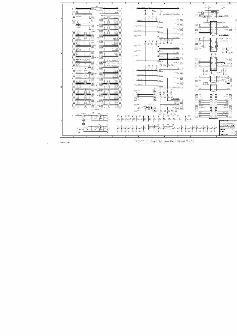
8/21/2019 D75 MANw_20121207.pdf
http://slidepdf.com/reader/full/d75-manw20121207pdf 115/128

8/21/2019 D75 MANw_20121207.pdf
http://slidepdf.com/reader/full/d75-manw20121207pdf 116/128
VU-75 VU Card - Load SheetD-75 / Dec 2007

8/21/2019 D75 MANw_20121207.pdf
http://slidepdf.com/reader/full/d75-manw20121207pdf 117/128

8/21/2019 D75 MANw_20121207.pdf
http://slidepdf.com/reader/full/d75-manw20121207pdf 118/128

8/21/2019 D75 MANw_20121207.pdf
http://slidepdf.com/reader/full/d75-manw20121207pdf 119/128
MBR-75 8 Position Mother Board (Right) - LoaD-75 / Dec 2005

8/21/2019 D75 MANw_20121207.pdf
http://slidepdf.com/reader/full/d75-manw20121207pdf 120/128

8/21/2019 D75 MANw_20121207.pdf
http://slidepdf.com/reader/full/d75-manw20121207pdf 121/128

8/21/2019 D75 MANw_20121207.pdf
http://slidepdf.com/reader/full/d75-manw20121207pdf 122/128
MBE-75 8 Position Mother Board (Extender) - LoD-75 / Dec 2004

8/21/2019 D75 MANw_20121207.pdf
http://slidepdf.com/reader/full/d75-manw20121207pdf 123/128
pagePR-75 Processor Board - Load SheetD-75 / Nov 2010
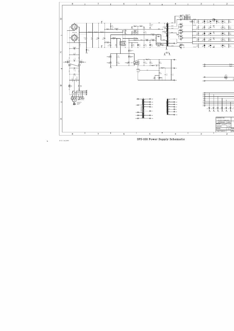
8/21/2019 D75 MANw_20121207.pdf
http://slidepdf.com/reader/full/d75-manw20121207pdf 124/128
F U S E
F 2
2 . 0
A
C 2 4
0 . 0
0 4 7 u F
C 2 5
0 . 0
0 4 7 u F
1.0M
R64
GNDP
F U S E
F 1
2 . 0
A
TP4
Z250LA40250V
V1
CGND
TP3
C47
2.2nF
270uF
C65
3
A
A
2
K
L 5
L 5
C 4 4
0 . 4
7 u F
C 3 1
0 . 4
7 u F
CGND
C 4 3
4 . 7 n F
C 3 7
4 . 7 n F
CGNDCGND
S G 5 5
R T 1
C49 4.7nF
1 . 0
M R 3 9
M
3
A
A
3 2 1 C T 2
1 2 3 C T 1
3
2
1
T1
14b
13b
12b
11b
10b
9b
8b
T1~V48P
~V36P
~V16P
~V8P
GND
~V8N
~V16N
UF4007 D13
UF4007 D14
10R59
1SMB59195.6V
Z4
1SMB59195.6V
Z5
4.99K
R42
1K
2
3
1CR1
4.99K
R41
GNDP
GND
1SMB59195.6V
Z2
1SMB59195.6V
Z3
1SMB59195.6V
Z6
22uF
C55
10R58
100nF
C63
11KR65
GNDP GND
40.2KR43 C48 0.1uF
1.30K
R45
26.7K
R44
+16V53.6KR48
M
3
A
A
1.00KR46
0.47uF
C56
1 . 0
M
R 4 0
CNY17
1
26
5
4
U2
K B L 0 8
D 7
0.1uF
C58
22uF
C54
1.00K
R63
KA431
1
2
3
U1
+8V
M B 3 5 1 0
D 1 2
WP1
WP2
WP3
6
3
T2
8
9
10
T2
2
5
T2
4
1
T2
13
12
11
T2
14
16
T2
20
19
18
17
T2
270uF
C62
FSCQ1265
3 1
4 2
U35
SYNC
PWM
DVCC
FB S
88.7KR60 88.7KR61 88.7KR62
330uF
C53
UF4007 D11
~V48P
~V36P
~V16N
~V16P
~V8P
~V8N
GND
DRN
+BR
2.00KR54
2.00KR55
3.32KR50
C51
0.001uF
2.43KR51
~V14A
~V8N
9
10
11
T1
16
15
14
13
12
T1
6
7
8
T1
~V28A
GNDP
~V14A
10.0KR57
10.0KR56
16VCC
C50
0.01uF
0.47uF
C61
GNDP
2.2nF
C59
2.2nF
C60
0.22uF
C57
4148D10
C45
1uF
C46
1uF
T P 1
T P 2
0.001uF C52
4148D8
SS14 D9
2.43KR52 2.43K R53
GNDPGNDP
D-75 / Jan 2009
B
C
A
D
5 4678
5 4678
P R 2
P R c h 1 1
P R c h 1 2
~V28A
P R f 1
P R f 2
SNB
+BR
P R 1
B R 2
2 8 V R
~V16P
~V16N
~V36P
~V48P
~V8P
2 8 V C
DRN
28VD
F E R
IN
F O R E T D - 3 9
T R A N S F O R M E
R
85-265 VAC50-60HzINPUT
INSTALL ONE
2.5V
1 0 m
H
1 0 m
H
F O R E T D - 3
4 T R A N S F O R M E R
Y Y
YY
NOTINSTALLED

8/21/2019 D75 MANw_20121207.pdf
http://slidepdf.com/reader/full/d75-manw20121207pdf 125/128
SPS-100 Power Supply Load SheD-75 / Jan 2009

8/21/2019 D75 MANw_20121207.pdf
http://slidepdf.com/reader/full/d75-manw20121207pdf 126/128
page Appendix – 1D-75 / Sep 2004
A P P E N D I X
Appendix
Contents
Replacement Parts List ............................................................... A-2
For the most part there are no user-replaceable parts in theD-75 console. Exceptions are those controls and components that in thecourse of normal use may need maintenance (i.e., faders, pots, ON/OFFswitches, indicator lamps, etc.). A complete list of available componentsfollws. Contact Wheatstone technical support for further information.
Wheatstone Corporation (600 Industrial Drive, New Bern, North Carolina,USA 28562) may be reached by phone at 252-638-7000, fax 252-637-1285,electronic mail “[email protected]”.

8/21/2019 D75 MANw_20121207.pdf
http://slidepdf.com/reader/full/d75-manw20121207pdf 127/128
page Appendix – 2D-75 / Sep 2004
A P P EN D I X
D-75 / June 2012
REPLACEMENT PARTS — D-75 DIGITAL AUDIO CONSOLE
COMPONENT DESCRIPTION WS P/N
ELUDOMTUPNIETELPMOCELUDOM57-NI "002900"
ELUDOMENOHPETELPMOCELUDOM57-PS "002901"
ELUDOMTUPTUOETELPMOCELUDOM57-MO "002902"
ELUDOMROTINOMMOORLORTNOCETELPMOCELUDOM57-RC "002903"
ELUDOMOIDUTSETELPMOCELUDOM57-CS "002904"
ELUDOMTCELESENILETELPMOCELUDOM57-SL "002905"
TR-75/FF MODULE COMPLETE FULL-FUNCTION TAPE REMOTE CONTROL MODULE "002906"
TR-75/SS MODULE COMPLETE START/STOP TAPE REMOTE CONTROL MODULE "002907"
YLBMESSADRACDEDAOLPMAERPCIMDAUQDRAC4-PMQ "005549"
ETALPECAFKNALB57-KB "002919"
STUPNIENILOERETSGOLANAROFDRAOBRETHGUADRETREVNOCD-OT-ADRAC57-CDA "002928"
STUPNILATIGIDROFDRACRETREVNOCETARELPMASDRAC57-CRS "002929"
DRACROSSECORPNIAMDRAC57-RP "002940"
DRACUVDELEGDIRBRETEMDRAC57-UV "002941"
)THGIR(DRAOBREHTOMECAFRETNINIAMDRAC57-RBM "002942"
)RETNEC(DRAOBREHTOMECAFRETNINOISNAPXEDRAC57-CEBM "002943"
)TFEL(DRAOBREHTOMECAFRETNINOISNAPXEDRAC57-LEBM "002944"
SPS-100 POWER SUPPLY RACKMOUNT POWER SUPPLY "007360"
SPS POWER SUPPLY CABLE CONSOLE POWER SUPPLY CABLE "007222"
CRYSTAL FOR 32 KHZ CONSOLE
SAMPLE RATE16.384 MHZ CRYSTAL "370010"
CRYSTAL FOR 44.1 KHZ CONSOLESAMPLE RATE
22.579 MHZ CRYSTAL "370011"
CRYSTAL FOR 48 KHZ CONSOLE
SAMPLE RATE24.576 MHZ CRYSTAL "370012"
WIRED REPLACEMENT FADER WIRED FADER FOR IN-75 MODULES "057501"
WIRED REPLACEMENT FADER WIRED FADER FOR SP-75 MODULES "057502"
WIRED REPLACEMENT SWITCH WIRED "ON/OFF" SWITCH "057503"
WIRED REPLACEMENT POT WIRED POT FOR CONTROL ROOM, STUDIO AND HEADPHONE MONITOR "057504"
LAUNAMS'RENWOLAUNAM "002999"

8/21/2019 D75 MANw_20121207.pdf
http://slidepdf.com/reader/full/d75-manw20121207pdf 128/128
A P P E N D I X
REPLACEMENT PARTS — D-75 DIGITAL AUDIO CONSOLE
COMPONENT DESCRIPTION WS P/N
I/O CONNECTOR 25 PIN CONNECTOR FOR MODULE I/O CONNECTIONS "200018"
REPLACEMENT SWITCH "ON/OFF" SWITCH "510063"
REPLACEMENT RED BUTTON MODULE "ON" BUTTON "530057"
REPLACEMENT AMBER BUTTON MODULE "OFF" BUTTON "530060"
RED LED REPLACEMENT MODULE "ON" BUTTON LED "600077"
YELLOW LED REPLACEMENT MODULE "OFF" BUTTON LED "600031"
SWITCH 2 POLE PUSHBUTTON MOMENTARY SWITCH "510113"
POT CONDUCTIVE PLASTIC DUAL LINEAR POT "500124"
POT KNOB 1/8" COLLET KNOB "520053"
POT CAP BURGUNDY CAP W/WHITE LINE "530039"
POT CAP DARK GREY CAP W/WHITE LINE "530040"
POT CAP BLUE CAP W/WHITE LINE "530045"
LUMA BUTTON WHITE LUMA BUTTON "530268"
LUMA BUTTON RED LUMA BUTTON "530269"
LUMA BUTTON YELLOW LUMA BUTTON "530270"
LUMA BUTTON GREEN LUMA BUTTON "530271"
RIBBON CABLE 50 CONDUCTOR RIBBON CABLE "150007"
RIBBON CABLE 26 CONDUCTOR RIBBON CABLE "150083"