d4.1 draft kpis, test specification and methodology · kpi key performance indicator mno mobile...
TRANSCRIPT
19/11/2011
Information and Communications Technologies Policy Support Programme (the “ICT PSP”) Information Society and Media Directorate-General Grant agreement no.: 270906 Pilot type A
D4.1 Draft KPIs, test specification and methodology
Version number: Version 1.2 Final Main author: NavCert GmbH, Germany Dissemination level: PU Lead contractor: ERTICO – ITS Europe Due date: 31st August 2011 Delivery date: 5th December 2011 Delivery date updated document

Page left intentionally blank

D4.1 Draft KPIs, test specification and methodology
05/12/2011 3 Version 1.2 Final
Control sheet
Version history
Version Date Main author Summary of changes
0.1 05.08.2011 Stefan Götte First draft version
0.2 12.09.2011 Stefan Götte Second draft version, partner input included
0.3 30.09.2011 Stefan Götte Third draft version after face-to-face meeting
0.4 04.10.2011 Stefan Götte Final draft version prepared
1.0 07.10.2011 Stefan Götte Final version prepared after review
1.1 19.11.2011 Stefan Götte Corrected and extended version after review done by ERTICO
1.2 Final 05.12.2011 Stefan Götte
Name Date
Prepared Stefan Götte, NavCert GmbH 07.10.2011
Reviewed Thom Verlinden (KLPD) , Anders Fagerholt (ERIC)
Andy Rooke
06.10.2011
05.12.2011
Authorized Andy Rooke 05.12.2011
Circulation
Recipient Date of submission
European Commission 05.12.2011

D4.1 Draft KPIs, test specification and methodology
19/11/2011 4 Version 1.2 Final
Table of contents
1 TERMS AND ABBREVIATIONS ................................................................................................................... 9
2 INTRODUCTION ..................................................................................................................................... 10
2.1 PURPOSE OF DOCUMENT...................................................................................................................... 10
2.2 STRUCTURE OF DOCUMENT .................................................................................................................. 10
2.3 HEERO CONTRACTUAL REFERENCES ..................................................................................................... 10
3 DEFINITION OF KEY PERFORMANCE INDICATORS (KPIS) ........................................................................ 12
3.1 GENERAL REQUIREMENTS FOR THE KPIS .............................................................................................. 12
3.1.1 REQUIREMENTS FROM STANDARDS ............................................................................................. 12
3.1.2 REQUIREMENTS FROM DOW ........................................................................................................ 14
3.2 GENERAL DEFINITIONS .......................................................................................................................... 15
3.2.1 DEFINITION OF PHASES AND SIGNIFICANT INSTANTS WITHIN THE ECALL PROCESS .................... 15
3.2.2 OVERVIEW OF KPIS ........................................................................................................................ 17
3.3 DEFINITION AND DESCRIPTION OF THE KPIS ........................................................................................ 19
3.3.1 KPI_001A: NUMBER OF AUTOMATICALLY INITIATED ECALLS ....................................................... 19
3.3.2 KPI_001B: NUMBER OF MANUALLY INITIATED ECALLS ................................................................. 19
3.3.3 KPI_002A: SUCCESS RATE OF COMPLETED ECALLS USING 112 ..................................................... 19
3.3.4 KPI_002B: SUCCESS RATE OF COMPLETED ECALLS USING LONG NUMBER .................................. 20
3.3.5 KPI_003: SUCCESS RATE OF RECEIVED MSDS ................................................................................ 20
3.3.6 KPI_004: SUCCESS RATE OF CORRECT MSDS ................................................................................. 20
3.3.7 KPI_005: DURATION UNTIL MSD IS PRESENTED IN PSAP .............................................................. 21
3.3.8 KPI_006: SUCCESS RATE OF ESTABLISHED VOICE TRANSMISSIONS .............................................. 21
3.3.9 KPI_007A: DURATION OF VOICE CHANNEL BLOCKING .................................................................. 21
3.3.10 KPI_007B: DURATION OF VOICE CHANNEL BLOCKING: AUTOMATIC RETRANSMISSION OF MSD 22
3.3.11 KPI_008: TIME FOR CALL ESTABLISHMENT ................................................................................... 22
3.3.12 KPI_009: ACCURACY OF POSITION ................................................................................................ 22
3.3.13 KPI_010: NUMBER OF USABLE SATELLITES ................................................................................... 23
3.3.14 KPI_011: GEOMETRIC DILUTION OF PRECISION (GDOP) ............................................................... 23
3.3.15 KPI_012: TIME BETWEEN SUCCESSFUL POSITIONING FIXES ......................................................... 23
3.3.16 KPI_013: SUCCESS RATE OF HEADING INFORMATION .................................................................. 24
3.3.17 KPI_014: SUCCESS RATE OF VIN DECODING WITHOUT EUCARIS .................................................. 24
3.3.18 KPI_015: SUCCESS RATE OF VIN DECODING WITH EUCARIS ......................................................... 24
3.3.19 KPI_016: TIME FOR VIN DECODING WITH EUCARIS ...................................................................... 25
D4.1 Draft KPIs, test specification and methodology
05/12/2011 5 Version 1.2 Final
3.3.20 KPI_017: DISPATCH TIME OF INCIDENT DATA TO RESCUE FORCES ............................................... 25
3.3.21 KPI_018: TIME TO ACTIVATE RESCUE FORCES ............................................................................... 25
3.3.22 KPI_019: DISPATCH TIME OF INCIDENT DATA TO TMC ................................................................. 26
3.3.23 KPI_020: SUCCESS RATE OF PRESENTED INCIDENT DATA IN TMC ................................................ 26
3.3.24 KPI_021: NUMBER OF SUCCESSFUL CALL-BACKS .......................................................................... 26
3.3.25 KPI_022: SUCCESS RATE OF CALL-BACKS ....................................................................................... 27
3.3.26 KPI_023: GSM NETWORK LATENCY ............................................................................................... 27
3.3.27 KPI_024: 112 NATIONAL NETWORK LATENCY ............................................................................... 27
3.3.28 KPI_025: 112 OPERATOR REACTION TIME .................................................................................... 27
3.3.29 KPI_026: TIME FOR ACKNOWLEDGEMENT OF EMERGENCY SERVICES ......................................... 28
3.3.30 KPI_027: TOTAL RESPONSE TIME .................................................................................................. 28
3.3.31 KPI_028: NUMBER OF CROSS-BORDER TESTS ............................................................................... 28
4 TEST SPECIFICATIONS AND METHODOLOGIES ........................................................................................ 30
4.1 GENERAL REQUIREMENTS FOR THE TEST SPECIFICATIONS AND METHODOLOGIES ............................ 30
4.1.1 REQUIREMENTS FROM DOW ........................................................................................................ 30
4.2 SUMMARY OF TEST SPECIFICATIONS AND METHODOLOGIES .............................................................. 31
4.2.1 TEST METHODOLOGIES FOR KPI MEASUREMENTS ....................................................................... 31
4.3 EVALUATION OF NETWORK CHARACTERISTICS .................................................................................... 49
4.3.1 KPI_NETWORK_001: VOICE CHANNEL DISTURBANCE ................................................................... 49
4.3.2 KPI_NETWORK_002: WEAK RADIO SIGNAL BEHAVIOR ................................................................. 49
4.3.3 TEST PROCEDURE: VOICE CHANNEL DISTURBANCE ...................................................................... 50
4.3.4 TEST PROCEDURE: WEAK RADIO SIGNAL BEHAVIOR..................................................................... 51
5 ANNEX I – MEMBER STATES TEST CHARACTERISTICS ............................................................................. 53
5.1 CROATIA ................................................................................................................................................ 53
5.1.1 IN GENERAL ................................................................................................................................... 53
5.1.2 TESTING ENVIRONMENT ............................................................................................................... 54
5.1.3 COUNTRY SPECIFIC MATTERS IN CROATIA .................................................................................... 58
5.2 CZECH REPUBLIC ................................................................................................................................... 59
5.2.1 IN GENERAL ................................................................................................................................... 59
5.2.2 TESTING ENVIRONMENT ............................................................................................................... 59
5.2.3 IVS TESTING ................................................................................................................................... 59
5.2.4 TEST PURPOSE FOR THE IVS .......................................................................................................... 60
5.2.5 SELECTION OF CONFORMANCE POINTS FOR THE PSAP EQUIPMENT ........................................... 61
5.2.6 TEST PURPOSE FOR THE PSAP EQUIPMENT .................................................................................. 61
5.2.7 TEST ENVIRONMENT DESCRIPTION ............................................................................................... 62
5.2.8 GNSS SIMULATOR .......................................................................................................................... 63

D4.1 Draft KPIs, test specification and methodology
19/11/2011 6 Version 1.2 Final
5.2.9 COUNTRY SPECIFIC MATTERS IN CZECH REPUBLIC........................................................................ 73
5.3 FINLAND ................................................................................................................................................ 74
5.3.1 IN GENERAL ................................................................................................................................... 74
5.3.2 TESTING ENVIRONMENT ............................................................................................................... 76
5.3.3 COUNTRY SPECIFIC MATTERS IN FINLAND .................................................................................... 79
5.4 GERMANY .............................................................................................................................................. 80
5.4.1 IN GENERAL ................................................................................................................................... 80
5.4.2 TESTING ENVIRONMENT ............................................................................................................... 80
5.4.3 COUNTRY SPECIFIC MATTERS IN GERMANY .................................................................................. 80
5.5 GREECE .................................................................................................................................................. 83
5.5.1 IN GENERAL ................................................................................................................................... 83
5.5.2 TESTING ENVIRONMENT ............................................................................................................... 83
5.5.3 COUNTRY SPECIFIC MATTERS IN GREECE ...................................................................................... 84
5.6 ITALY ...................................................................................................................................................... 85
5.6.1 IN GENERAL ................................................................................................................................... 85
5.6.2 TESTING ENVIRONMENT ............................................................................................................... 87
5.6.3 COUNTRY SPECIFIC MATTERS IN ITALY .......................................................................................... 89
5.7 ROMANIA .............................................................................................................................................. 90
5.7.1 IN GENERAL ................................................................................................................................... 90
5.7.2 TESTING ENVIRONMENT ............................................................................................................... 90
5.7.3 COUNTRY SPECIFIC MATTERS IN ROMANIA .................................................................................. 92
5.8 SWEDEN ................................................................................................................................................ 93
5.8.1 IN GENERAL ................................................................................................................................... 93
5.8.2 TESTING ENVIRONMENT ............................................................................................................... 93
5.8.3 COUNTRY SPECIFIC MATTERS IN SWEDEN .................................................................................... 94
5.9 THE NETHERLANDS ............................................................................................................................... 95
5.9.1 IN GENERAL ................................................................................................................................... 95
5.9.2 TESTING ENVIRONMENT ............................................................................................................... 97
5.9.3 COUNTRY SPECIFIC MATTERS IN THE NETHERLANDS ................................................................. 100
6 ANNEX II – OVERVIEW OF RESULT SHEETS FOR EVALUATION .............................................................. 101
6.1 SHEET: SUMMARY ............................................................................................................................... 101
6.2 SHEET: RESULTS PER IVS ...................................................................................................................... 102
6.3 SHEET: RESULTS PER PSAP .................................................................................................................. 103
6.4 SHEET: EXAMPLE FOR RESULTS OF IVS TESTS ..................................................................................... 104
6.5 SHEET: REAL LIFE – TEST CONDITIONS ................................................................................................ 105
D4.1 Draft KPIs, test specification and methodology
05/12/2011 7 Version 1.2 Final
Figures
FIGURE 1: RELATIONS OF TIMING ISSUES 16
FIGURE 2: ECALL SCHEMATIC 38
FIGURE 3: CROATIAN TEST SCENARIOS 54
FIGURE 4: CROATIAN ECALL PILOT ARCHITECTURE 55
FIGURE 5: CZECH LABORATORY CONFIGURATION 62
FIGURE 6: REAL ENVIRONMENT CONFIGURATION 62
FIGURE 7: GNSS SIMULATOR 63
FIGURE 8: GEOMETRIC CONFIGURATION OF THE GNSS SATELLITES 64
FIGURE 9: SATELLITES POSITION AND MOVEMENT OVER TIME 65
FIGURE 10: DISPLAY OF RECEIVED SIGNAL LEVELS 65
FIGURE 11: DISPLAY OF SETTING CONCERNING SIGNAL LEVELS 65
FIGURE 12: TESTING SCHEME 66
FIGURE 13: MULTIPATH SCENARIO 67
FIGURE 14: MULTIPATH SIGNAL RECEPTION 68
FIGURE 15: MANUAL MULTIPATH SETTINGS 68
FIGURE 16: GROUND REFLECTION PRINCIPLE 69
FIGURE 17: GROUND REFLECTION SETTINGS 69
FIGURE 18: GNSS SIGNAL OBSCURATION I 70
FIGURE 19: GNSS SIGNAL OBSCURATION II 70
FIGURE 20: GNSS SIGNAL PATH HEMISPHERE 71
FIGURE 21: RECEPTION IN A VEHICLE ANTENNA 71
FIGURE 22: ANTENNA MODEL I 72
FIGURE 23: ANTENNA MODEL II 72
FIGURE 24: MOVING OBJECTS PROFILE SETTINGS 73
FIGURE 25: SENSOR MODEL 73
FIGURE 26: HEERO FINNISH PILOT SYSTEM ARCHITECTURE OUTLINE 74
FIGURE 27: PILOT ECALL TESTING IN FINLAND 78
FIGURE 28: CROSS BORDERS TESTS USING THE FINNISH PILOT SYSTEM ECALL SENDER AND RECEIVER PARTS 79
FIGURE 29: ECALL SERVICE CHAIN IN THE ITALIAN PILOT 86
FIGURE 30: HEERO AND DUTCH PROJECT PHASES 96

D4.1 Draft KPIs, test specification and methodology
19/11/2011 8 Version 1.2 Final
Tables
TABLE 1: ECALL STANDARDS FOR HEERO 13
TABLE 2: KPIS TO BE EVALUATED WITHIN THE MEMBER STATES 18
TABLE 3: KPIS AND APPLICABLE TEST PROCEDURES 32
TABLE 4: KPIS EVALUATED IN GERMANY 81
TABLE 5: OVERVIEW OF GREEK LABORATORY TEST SCENARIOS 83
TABLE 6: OVERVIEW OF GREEK REAL TRAFFIC TEST SCENARIOS 83
TABLE 7: OVERVIEW OF SWEDISH TEST ACTIVITIES 94
TABLE 8: OVERVIEW OF DUTCH PROJECT PHASES 96
TABLE 9: DUTCH TEST PER PROJECT PHASE 97
TABLE 10: DUTCH TEST SCENARIO 1 98
TABLE 11: DUTCH TEST SCENARIO 2 98
TABLE 12: DUTCH TEST SCENARIO 3 98
TABLE 13: DUTCH TEST SCENARIO 4 98
TABLE 14: DUTCH TEST SCENARIO 5 98
TABLE 15: DUTCH TEST SCENARIO 6 99
TABLE 16: DUTCH TEST SCENARIO 7 99
TABLE 17: DUTCH TEST SCENARIO 8 99
TABLE 18: DUTCH TEST SCENARIO 9 99
TABLE 19: DUTCH TEST SCENARIO 10 99
TABLE 20: SUMMARY OF DUTCH TEST SCENARIOS 100

D4.1 Draft KPIs, test specification and methodology
05/12/2011 9 Version 1.2 Final
1 Terms and abbreviations
Abbreviation Definition
3GPP Third Generation Partnership Project CAN Controller Area Network CEN Comité Européen de Normalisation CIP Competitiveness and Innovation Framework Programme DoW Description of Work EC European Commission EGNOS European Geostationary Navigation Overlay System ENT Ericsson Nikola Tesla ETSI European Telecommunication Standards Institute EUCARIS EUropean CAR and driving License Information System GDOP Geometric dilution of precision GIS Geographic Information System GLONASS Globalnaja Nawigazionnaja Sputnikowaja Sistema GNSS Global Navigation Satellite System GPS Global Positioning System GPRS General Packet Radio System GSM Global System of Mobile telecommunications ISO International Standardization Organization IVS In-Vehicle System KPI Key Performance Indicator MNO Mobile Network Operator MSD Minimum Set of Data MSISDN Mobile Subscriber Integrated Services Digital Network Number NIST National Institute of Standards and Technology NMEA National Marine Electronics Association PLMN Public Land Mobile Network PSAP Public Service Answering Point SBAS Satellite Based Augmentation System SIM Subscriber Identity Module TPS Third Party Service TMC Traffic Management Centre UMTS Universal Mobile Telecommunication System USB Universal Serial Bus VAS Value Added Services VIN Vehicle Identification Number VPN Virtual Private Network
Term Definition
Process The method of operation in any particular stage of development of the material part, component or assembly involved.
D4.1 Draft KPIs, test specification and methodology
19/11/2011 10 Version 1.2 Final
2 Introduction
2.1 Purpose of Document
The purpose of this document is to define a common base to allow the evaluation of the
achieved results of all participating member states. This document will provide the first draft
for discussions and consolidations. Thus the document describes the Key Performance
Indicators (KPIs) to evaluate the performances of the different eCall implementations of the
Member States in a comparable way. This requires that test scenarios and test
methodologies are defined in such a way to allow implementation in all participating member
states. In addition due to the variety within the Member States, processes and procedures on
European level will be complemented on a national level.
2.2 Structure of Document
The document is structured into three main sections, one concerning the definition of the
KPIs and one related to test scenarios and test methodologies. The last section (annex)
provides details on methodologies and procedures per member state if necessary. For the
KPI section there is a list of all identified KPIs with one definition. Each participating member
state selects the KPIs which are applicable to its national pilot, multi-country or ERA
GLONASS tests. In the second section, test scenarios and methodologies are described. In
addition, national methodologies and testing procedures are if necessary provided as annex
per member state to reflect the different set up of the national pilots.
2.3 HeERO Contractual References
HeERO (Harmonised eCall European Pilot) is a Pilot type A of the ICT Policy Support
Programme (ICT PSP), Competitiveness and Innovation Framework Programme (CIP).
The Grant Agreement number is 270906 and project duration is 36 months, effective from 01
January 2011 until 31 December 2013. It is a contract with the European Commission, DG
INFSO.
The principal EC Project Officer is:
Emilio Davila-Gonzalez
EUROPEAN COMMISSION DG INFSO Office: BU 31 – 4/50

D4.1 Draft KPIs, test specification and methodology
05/12/2011 11 Version 1.2 Final
B - 1049 Brussels Tel: +32 296 2188 E-mail: [email protected]
Two other Project Officer will follow the HeERO project:
• Eva Boethius ([email protected])
• Pierpaolo Tona ([email protected])
Address to which all deliverables and reports have to be sent:
Emilio Davila-Gonzalez EUROPEAN COMMISSION DG INFSO BU 31 – 4/50 B - 1049 Brussels Tel: +32 296 2188
by mail: [email protected]
Any communication or request concerning the grant agreement shall identify the grant
agreement number, the nature and details of the request or communication and be submitted
to the following addresses:
European Commission Information Society and Media Directorate-General B-1049 Brussels Belgium
by electronic mail:
D4.1 Draft KPIs, test specification and methodology
19/11/2011 12 Version 1.2 Final
3 Definition of Key Performance Indicators (KPIs)
3.1 General requirements for the KPIs
3.1.1 Requirements from standards
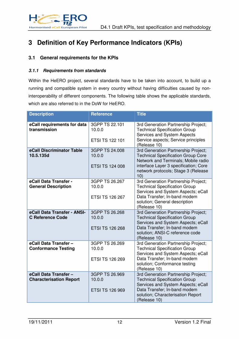
Within the HeERO project, several standards have to be taken into account, to build up a
running and compatible system in every country without having difficulties caused by non-
interoperability of different components. The following table shows the applicable standards,
which are also referred to in the DoW for HeERO.
Description Reference Title
eCall requirements for data transmission
3GPP TS 22.101 10.0.0
ETSI TS 122 101
3rd Generation Partnership Project; Technical Specification Group Services and System Aspects Service aspects; Service principles (Release 10)
eCall Discriminator Table 10.5.135d
3GPP TS 24.008 10.0.0
ETSI TS 124 008
3rd Generation Partnership Project; Technical Specification Group Core Network and Terminals; Mobile radio interface Layer 3 specification; Core network protocols; Stage 3 (Release 10)
eCall Data Transfer - General Description
3GPP TS 26.267 10.0.0
ETSI TS 126 267
3rd Generation Partnership Project; Technical Specification Group Services and System Aspects; eCall Data Transfer; In-band modem solution; General description (Release 10)
eCall Data Transfer - ANSI-C Reference Code
3GPP TS 26.268 10.0.0
ETSI TS 126 268
3rd Generation Partnership Project; Technical Specification Group Services and System Aspects; eCall Data Transfer; In-band modem solution; ANSI-C reference code (Release 10)
eCall Data Transfer – Conformance Testing
3GPP TS 26.269 10.0.0
ETSI TS 126 269
3rd Generation Partnership Project; Technical Specification Group Services and System Aspects; eCall Data Transfer; In-band modem solution; Conformance testing (Release 10)
eCall Data Transfer – Characterisation Report
3GPP TS 26.969 10.0.0
ETSI TS 126 969
3rd Generation Partnership Project; Technical Specification Group Services and System Aspects; eCall Data Transfer; In-band modem solution; Characterisation Report (Release 10)

D4.1 Draft KPIs, test specification and methodology
05/12/2011 13 Version 1.2 Final
eCall Data Transfer – Technical Report - Characterisation Report
3GPP TR 26.969 10.0.0
ETSI TR 126 969
3rd Generation Partnership Project; Technical Specification Group Services and System Aspects; eCall Data Transfer; In-band modem solution; Characterisation Report (Release 10)
eCall minimum set of data CEN EN 15722 Date: 2010-11
Road transport and traffic telematics – eSafety – eCall minimum set of data - Draft EN 081018
Pan European eCall Operating Requirements
CEN EN 16072 Date: 2010-9
Intelligent transport systems – eSafety – Pan European eCall - Operating requirements
High Level Application Protocols
CEN EN 16062 Date: 2010-9
Intelligent Transport Systems – eCall – High Level Application Protocols
Data registry procedures ISO/EN 24978:2009 Intelligent transport systems - ITS Safety and emergency messages using any available wireless media - Data registry procedures
Table 1: eCall standards for HeERO
These standards form the basis of the KPIs’ that have to be developed, to evaluate the
capabilities of the eCall system components in order to fulfil the requirements of these
standards. In particular the following elements are of prime importance:
• the timings within the communication process between IVS and PSAP.
• the use of the eCall flag (Service Category) in the emergency call setup procedure.
• the correct generation coding, transmission of the MSD
• decoding and presentation of the MSD.
On the one hand this might lead to further development activities in terms of non-conformant
system components, on the other hand, the results of this pilot project may lead to
refinement/changes within the specifications if it is obvious that a requirement cannot be
fulfilled at all or is even contradictory to another standard.

D4.1 Draft KPIs, test specification and methodology
19/11/2011 14 Version 1.2 Final
3.1.2 Requirements from DoW
The objectives of HeERO, as written in the Description of Work, for the definition and
selection of KPIs are to:
• Validate requirements of eCall standards and specifications
• Identify measurable parameters which are comparable between Member and
Associated States, independent of organizational structure
• Analyze the complete process chain from initiation of a call to dispatch of rescue
forces
To analyze the suitability of eCall for a Pan European deployment, it is necessary, to define
KPIs measuring the above mentioned objectives.
D4.1 Draft KPIs, test specification and methodology
05/12/2011 15 Version 1.2 Final
3.2 General definitions
3.2.1 Definition of phases and significant instants within the eCall process
Due to the fact, that many of the defined KPIs are based on timing issues and the clear
common understanding within the project is essential, we defined the following:
• The point of time, where the IVS starts the process to get in contact with the PSAP is
called “call connection initiation”, the corresponding phase starting here is called “call
establishment”
• The phase, where the transmission of the MSD happens is called “data transmission”
• The phase, where the voice communication happens is called “voice transmission”
In addition, the following significant instants are defined with respect to the module where the
measurement takes place (IVS, PSAP, emergency service)
• T0-IVS: IVS initiated the eCall (start of phase “call establishment”)
• T1-IVS: IVS starts the MSD transmission (start of phase “data transmission”)
• T2-IVS: End of phase “data transmission”
• T0-PSAP: Initiated eCall is indicated at PSAP
• T1-PSAP: Start of MSD reception at PSAP
• T2-PSAP: Start of phase “voice transmission”
• T3-PSAP: Start of dispatching information about incident to emergency services
• T4-PSAP: Start of dispatching information about incident to TMC
• T3-ES: Start of confirmation about incident handling to PSAP
• T4-ES: Start of dispatching rescue forces
The next page depicts a diagram showing the relationship between the timing issues
mentioned here

D4.1 Draft KPIs, test specification and methodology
19/11/2011 16 Version 1.2 Final
Figure 1: Relations of timing issues
IVS PSAP ES TMC
T0-IVS T0-PSAP
T1-IVS
T2-IVS
T1-PSAP
T2-PSAP
T3-PSAP
T4-PSAP
RF
T3-ES
TMC
T4-ES RF
eCall initiation
Call establishment phase
Start MSD transmission
Data transmission phase
Voice transmission phase
End MSD transmission
t0
t0+∆t
PSAP eCall processing phase
ES
PSAP

D4.1 Draft KPIs, test specification and methodology
05/12/2011 17 Version 1.2 Final
3.2.2 Overview of KPIs
The following table gives an overview which part of the eCall-system will be evaluated via a
KPI in which country as committed by the Member States within the DoW (X = will be tested,
(X) = will be tested if possible, -- = will not be tested) or between member states for cross
border respective ERA GLONASS tests.
The table describes all KPIs which are applicable in any of the participating member states.
Every member state has selected those KPIs which are appropriate for each single Member
State to be evaluated according to their original planning and resource calculation for the
HeERO project.
ID o
f K
PI
Nam
e o
f K
PI
Member States, where KPI is evaluated
Cro
ati
a
Czech
Rep
ub
lic
Fin
lan
d
Germ
an
y
Gre
ece
Italy
Ro
man
ia
Sw
ed
en
Th
e N
eth
erl
an
ds
Cro
ss b
ord
er
ER
A G
LO
NA
SS
KPI_001a Number of automatically initiated eCalls
X X -- X -- X X X X
KPI_001b Number of manually initiated eCalls
X -- X X X X X X X
KPI_002a Success rate of completed eCalls using 112
X X -- (X) X X X X X
KPI_002b
Success rate of completed eCalls using long number
X -- X X -- -- X (X) X
KPI_003 Success rate of received MSDs
X X X X -- X X X X
KPI_004 Success rate of correct MSDs
X X X X X X X X X
KPI_005
Duration until MSD is presented in PSAP
-- X -- X X X X (X) X
KPI_006 Success rate of established voice transmissions
X X -- X X X X X X
KPI_007a Duration of voice channel blocking
X -- -- X -- -- X (X) (X)
KPI_007b
Duration of voice channel blocking: automatic retransmission of MSD
-- (X) -- -- -- -- X X --
KPI_008 Time for call establishment
X X -- (X) X X -- -- X

D4.1 Draft KPIs, test specification and methodology
19/11/2011 18 Version 1.2 Final
Table 2: KPIs to be evaluated within the Member States Pilot Sites
KPI_009 Accuracy of position
X X -- X -- -- -- -- X
KPI_010 Number of usable satellites
X X -- -- -- -- -- -- --
KPI_011 Geometric dilution of precision
X X -- -- -- -- -- -- --
KPI_012 Time between successful positioning fixes
X (X) -- -- -- -- -- -- --
KPI_013 Success rate of heading information
-- -- -- X -- -- -- -- X
KPI_014
Success rate of VIN decoding without EUCARIS
X X X -- -- -- X -- --
KPI_015 Success rate of VIN decoding with EUCARIS
-- -- -- (X) -- X X -- X
KPI_016 Time for VIN decoding with EUCARIS
-- -- -- -- -- -- X -- X
KPI_017 Dispatch time of incident data to rescue forces
X X -- -- -- X X -- --
KPI_018 Time to activate rescue forces
-- X -- -- -- -- X -- --
KPI_019 Dispatch time of incident data to TMC
-- (X) X -- -- -- X -- X
KPI_020
Success rate of presented incident data in TMC
-- (X) -- -- -- -- X -- X
KPI_021 Number of successful call-backs
-- X -- -- -- X X -- --
KPI_022 Success rate of call-backs
-- X -- -- -- X X -- X
KPI_023 GSM network latency
-- X -- -- -- -- X -- --
KPI_024 112 National network latency
-- (X) -- -- -- -- X -- --
KPI_025 112 Operator reaction time
-- -- -- -- -- -- X (X) --
KPI_026
Time for acknowledgement of emergency services
-- X -- -- -- -- X X --
KPI_027 Total response time
-- X -- -- -- -- X X --
KPI_028 Number of cross-border tests
-- (X) -- -- -- (X) X X --

D4.1 Draft KPIs, test specification and methodology
05/12/2011 19 Version 1.2 Final
3.3 Definition and description of the KPIs
A KPI measures the quality of specified services during a period of time. In order to allow a
qualification of the achieved results thresholds are defend to indicate what is regarded as
poor, acceptable, good or excellent achievement. Within HeERO however the goal is not to
measure the quality of the implementation or operation of eCall in the member states.
Instead the KPIs will provide guidance on the suitability of eCall (protocol, procedures,
parameters, etc) for later deployment. For this reason there is no necessity to allocate
thresholds to the KPIs to allow measurement of success. Based on the evaluation of the
achieved KPIs for the second phase specific adjustment might be required to improve overall
performance of the system.
3.3.1 KPI_001a: Number of automatically initiated eCalls
This KPI measures the total number of automatically initiated eCalls
Unit: unit-less
Definition: Every automatic initiation of an eCall is counted up to get an overview of the
total number of automatically initiated eCalls.
3.3.2 KPI_001b: Number of manually initiated eCalls
This KPI measures the total number of manually initiated eCalls
Unit: unit-less
Definition: Every manual initiation of an eCall is counted up to get an overview of the
total number of manually initiated eCalls.
3.3.3 KPI_002a: Success rate of completed eCalls using 112
This KPI describes the relation between the number of initiated eCalls at a given period of
time versus the number of successful completed eCalls while the 112 is used as telephone
number for the emergency call.
Unit: [%]
Definition: eCall success rate = successful eCalls / all initiated eCalls * 100 %
Successful eCalls = initiated eCalls - failed eCalls

D4.1 Draft KPIs, test specification and methodology
19/11/2011 20 Version 1.2 Final
General definition of successful eCall: Voice call path was established, MSD data transfer
was done and MSD content was shown at operator’s desk.
Initiated eCall: eCall triggered by IVS
Failed eCall: Either no establishment of a voice path connection at all, or no stable
connection at all, or no voice call possible or no MSD transmission or faulty MSD transmitted
3.3.4 KPI_002b: Success rate of completed eCalls using long number
This KPI describes the relation between the number of initiated eCalls at a given period of
time versus the number of successful completed eCalls while the long number of a PSAP is
used as telephone number for the emergency call.
Detailed description: See KPI_002a.
3.3.5 KPI_003: Success rate of received MSDs
This KPI describes the relation between the number of initiated MSD transmissions versus
the number of successful presented MSD contents at the operator’s desk, at which it is not
arbitrative, if the content itself is correct or not for those cases where the eCall was not
successfully completed, e g. voice communication not established or not possible.
Unit: [%]
Definition: MSD success rate = successful MSDs / all initiated MSDs * 100 %
Successful MSDs = initiated MSDs - failed MSDs
General definition of successful MSD: Content is presented at operator’s desk in PSAP
Initiated MSD: Start of MSD-transmission in push mode (comes from IVS)
Failed MSD: No MSD data transmission or faulty transmission: voice call started without
content of MSD is presented at operator’s desk in PSAP or MSD transmission
is not successfully completed.
3.3.6 KPI_004: Success rate of correct MSDs
This KPI describes the correctness of the coding, transmission, decoding and presentation of
the MSD.
Unit: [%]

D4.1 Draft KPIs, test specification and methodology
05/12/2011 21 Version 1.2 Final
Definition: MSD correctness rate = correct MSDs / all received MSDs * 100 %
correct MSDs = received MSDs - incorrect MSDs
General definition of correct MSD: The decoded MSD presented to the operator in PSAP has
the same content as the one sent by the IVS.
Incorrect MSD: The content decoded and presented in PSAP is not the same sent by IVS.
3.3.7 KPI_005: Duration until MSD is presented in PSAP
This KPI describes the duration from the initiation (automatically or manually) of an eCall to
the presentation of the MSD content in the PSAP.
Unit: [s]
Definition: MSD presentation time = point of time of presentation of MSD at operator’s
desk in PSAP (T2-PSAP) - point of time for IVS initiated the eCall (T0-IVS)
3.3.8 KPI_006: Success rate of established voice transmissions
This KPI describes the relation between the number of initiated voice transmissions versus
the number of successful establishments of voice transmissions between the vehicle and the
PSAP.
Unit: [%]
Definition: Voice transmission success rate = successful voice transmissions / all initiated
voice transmissions * 100 %
General definition of successful voice transmission: operator in PSAP and passenger in
vehicle can talk, which means speaking to and hearing from each other is possible at both
sites.
3.3.9 KPI_007a: Duration of voice channel blocking
This KPI represents the time the transmission of MSD blocks the voice channel. The time the
voice channel is blocked can be defined as a time between successful call setup
(“connected” is reported by the network) and the opening of voice communication in both
directions after the MSD has been transmitted successfully or the MSD transmission has
D4.1 Draft KPIs, test specification and methodology
19/11/2011 22 Version 1.2 Final
been abandoned (after time out) and the voice communication has been opened on both
sides in both directions.
Unit: [ms]
Definition: Duration of voice channel blocking = start of phase “voice transmission” (T2-
PSAP) - IVS starts MSD transmission (T1-IVS)
The "voice connection established" signal can be defined as the point of time when the IVS
and the PSAP have both opened the voice communication channel after the transmission of
MSD.
Completion of call setup can be defined as a point of time when the IVS attached to a GSM
or UMTS PLMN moves from state "alerting" to state "call established" or “connected”.
3.3.10 KPI_007b: Duration of voice channel blocking: automatic retransmission of
MSD
Referring to KPI_008, this KPI evaluates the duration of the voice channel blocking if an
automatic retransmission of the MSD is initiated by the IVS.
3.3.11 KPI_008: Time for call establishment
This KPI refers to the observed time difference between the time of the eCall initiation
(automatic and manual) and the time of the eCall reception at PSAP. The value of this KPI is
to be determined by the two event logs comparison, as follows:
Unit: [s]
Definition: Time for call establishment = start of eCall reception at PSAP (T0-PSAP) - point
of time for IVS initiated the eCall (T0-IVS)
3.3.12 KPI_009: Accuracy of position
This KPI describes the differences between the reported position by IVS and the actual
position of the vehicle. As it can happen under difficult environmental conditions, that the
amount of visible satellites in not sufficient for a proper fix of the position, this KPI should give
also an impression if the usage of only GPS is enough to get a correct position information or
if further GNSS (like Galileo) are needed.
Unit: [m] if reference system with reliable accuracy is used. Otherwise “acceptable”,
D4.1 Draft KPIs, test specification and methodology
05/12/2011 23 Version 1.2 Final
“not acceptable” depending on the distance
Definition: Accuracy of position = reported position - actual position measured by
reference system or
“acceptable”, if reported position is close to reported position in voice
communication / “non-acceptable”, if reported position is more than 100 m
away from communicated position
3.3.13 KPI_010: Number of usable satellites
This KPI collects the number of actually visible satellites in operation in every particular case
of position estimation.
Unit: unit-less
Definition: Number of visible and operational satellites, as reported by the satellite
navigation (GPS) receiver
3.3.14 KPI_011: Geometric dilution of precision (GDOP)
This KPI refers to the estimate of position estimation error due to spatial distribution of
satellites used for position estimation.
Unit: unit-less
Definition: GDOP, as reported by satellite navigation (GPS) receiver
3.3.15 KPI_012: Time between successful positioning fixes
This KPI refers to duration of time interval between two consecutive successful positioning
fixes, thus defining the estimation of position estimation uncertainty at the certain vehicle
velocity due to the age of position estimates.
Unit: [s]
Definition: Time between successful positioning fixes = time stamp of nth position
estimation - time stamp of nth-1 position estimation

D4.1 Draft KPIs, test specification and methodology
19/11/2011 24 Version 1.2 Final
3.3.16 KPI_013: Success rate of heading information
This KPI describes the correctness of the heading information of the vehicle. To get this
value, the last three position information are evaluated and integrated in the IVS. This
information is especially needed if the vehicle has a collision on the motorway and the rescue
forces have to know in which direction the vehicle drove to take the correct ramp to the
motorway.
Furthermore, is has to be evaluated, if the last three positions can give a more reliable
statement about the direction of the car than the MSD data concerning “vehicle direction”
(Direction of travel in 2°-degrees steps from magnetic north (0 - 358, clockwise)).
Unit: [%]
Definition: Heading information success rate = correct heading information / all reported
heading information * 100 %;
“Correct” if degree is within 75 degree concerning the direction of the vehicle
on the road, or compass point is between neighboring directions of N, NE, E,
SE, S, SW, W, NW.
“Incorrect”, if above mentioned parameters do not fit at all.
3.3.17 KPI_014: Success rate of VIN decoding without EUCARIS
This KPI will show the correct encoding and decoding of the vehicle identification. The
information about the vehicle having a collision can be very important for the rescue forces
as they will know beforehand, which type of car has a collision and which tools might be
useful to take with.
Unit: [%]
Definition: VIN success rate = correct reported information about vehicle by database /
all requests at database * 100 %;
“Correct” if provided VIN is identical and presented data fits to type of vehicle
(interface to database is correctly implemented), otherwise “Incorrect”.
3.3.18 KPI_015: Success rate of VIN decoding with EUCARIS
Another possibility to get information about a vehicle is the database called EUCARIS. This
database is used in the EU for data exchanges concerning vehicles and driving licenses

D4.1 Draft KPIs, test specification and methodology
05/12/2011 25 Version 1.2 Final
between Member States. So, after decoding of the VIN by the PSAP, a connection to
EUCARIS shall be established, to get information about the vehicle. The KPI describes how
many requests at this database lead to correct provided information by EUCARIS.
Unit: [%]
Definition: VIN EUCARIS success rate = correct reported information about vehicle by
EUCARIS / all requests from PSAP for information at EUCARIS * 100 %
3.3.19 KPI_016: Time for VIN decoding with EUCARIS
This KPI describes the time needed for a successful establishment of the connection and the
data transfer and will so provide an overview about the duration of the complete process.
Unit: [s]
Definition: EUCARIS decoding time = point of time the decoded VIN is presented on
operator’s desk - point of time the request was initiated by PSAP
3.3.20 KPI_017: Dispatch time of incident data to rescue forces
This KPI represents the time needed, until the PSAP starts to dispatch all necessary
information to associated emergency services.
Unit: [s]
Definition: Needed time until information dispatch = start of dispatching information to
rescue services (T3-PSAP) - point of time for IVS initiated the eCall (T0-IVS)
The “information dispatched” signal has to be defined before data collection or evaluation
can start. One possible definition for “information dispatched” signal is the moment when
PSAP has sent information about the event to relevant field units.
3.3.21 KPI_018: Time to activate rescue forces
This KPI represents mean time needed for activation of rescue forces for sufficient number of
processed tests. Time is measured from reception of the eCall by the PSAP until the rescue
forces go for help (exit the garage etc.).
Unit: [s]

D4.1 Draft KPIs, test specification and methodology
19/11/2011 26 Version 1.2 Final
Definition: Rescue forces activation time = point of time the rescue forces are dispatched
(T4-ES) - point of time the eCall was indicated at PSAP (T0-PSAP)
3.3.22 KPI_019: Dispatch time of incident data to TMC
This KPI refers to the time it takes to inform the TMC operators after the occurring of the
collision
Unit: [s]
Definition: Needed time until incident data is presented = point of time of presentation of
incident data at operator’s desk in TMC - point of time for IVS initiated the
eCall (T0-IVS)
3.3.23 KPI_020: Success rate of presented incident data in TMC
This KPI refers to the relation between the number of initiated eCalls versus the number of
successful received cases in the TMC
Unit: [%]
Definition: Successful presented incidents in TMC = received incidents in TMC / all
initiated eCalls * 100 %
3.3.24 KPI_021: Number of successful call-backs
This KPI refers to the number of successful call-backs from PSAP to IVS.
Unit: unit-less
Definition: Every successful call-back is counted up, to get an overview of the total
number of successful call-backs.
Note: A Call-Back is only possible, if the IVS has established (or attempted to
establish) an eCall to the PSAP. Between the termination of the initial eCall
and the initiation of a call-back the PSAP shall wait at least [20] sec to allow
the network to perform “housekeeping”, otherwise the IVS may be reported as
“not reachable”.

D4.1 Draft KPIs, test specification and methodology
05/12/2011 27 Version 1.2 Final
3.3.25 KPI_022: Success rate of call-backs
This KPI refers to the number of successful call-backs from PSAP to IVS, compared with the
number of attempted call-backs.
Unit: [%]
Definition: call-back success rate = successful call-back / all initiated call-backs * 100 %
Successful call-backs = initiated call-backs - failed call-backs
Failed call-back = The PSAP Operator can’t confirm bi-directional voice
connection during call-back.
Initiated call-back = The PSAP Operator has confirmed bi-directional voice
connection for the initial call and has initiated a call-back after sending
CLEARDOWN to the IVS.
3.3.26 KPI_023: GSM network latency
This KPI will measure the time it will take a call to pass through the GSM network before
reaching the 112 national network.
Unit: [s]
Definition: GSM network latency = point in time when the call enters the 112 national
network - point of time for IVS initiated the eCall (T0-IVS)
3.3.27 KPI_024: 112 National network latency
This KPI will measure the time it will take a call to pass through the 112 national network
before reaching the PSAP.
Unit: [ms]
Definition: 112 network latency = point in time the call reaches the PSAP - point in time
the call reaches the 112 network
3.3.28 KPI_025: 112 Operator reaction time
This KPI will measure the time it takes an operator to answer a call once it is presented with
a visual or audio notification.
D4.1 Draft KPIs, test specification and methodology
19/11/2011 28 Version 1.2 Final
Unit: [ms]
Definition: 112 operator reaction time = point in time the operator answers the call - point
in time the operator is notified about a call
3.3.29 KPI_026: Time for acknowledgement of emergency services
This KPI will measure the time it takes the emergency services to acknowledge the
information sent by the 112 PSAP.
Unit: [ms]
Definition: Emergency services availability = point in time the emergency services
acknowledge the call (T3-ES) - point in time the 112 PSAP dispatches the
necessary information (T3-PSAP)
This KPI should be measured separately for every emergency service alerted by the 112
PSAP operators.
3.3.30 KPI_027: Total response time
This KPI will measure the total response time for the whole operational flow from the time of
the collision until the emergency resources reach the incident scene.
Unit: [s]
Definition: Total response time = point in time the emergency resources reach the
incident scene - point of time for IVS initiated the eCall (T0-IVS)
3.3.31 KPI_028: Number of cross-border tests
This KPI will measure the number of tests that have been done with a foreign IVS.
Unit: unit-less
Definition: Every test done with a foreign IVS is counted up to get an overview of the total
number of tests done with foreign equipment.
A “foreign” IVS is either
• a “national” IVS with foreign SIM card (testing the roaming)
• a “non-national” IVS with national SIM card

D4.1 Draft KPIs, test specification and methodology
05/12/2011 29 Version 1.2 Final
• a “non-national” IVS with foreign SIM card,
where a “national” IVS is used as standard equipment in the respective
member state and where a”non-national” IVS is not used as standard
equipment in the respective member state.
Note: This KPI does not include cases, where an IVS is situated in one country near
the borderline and the eCall is received in a PSAP in a “foreign” country.

D4.1 Draft KPIs, test specification and methodology
19/11/2011 30 Version 1.2 Final
4 Test specifications and methodologies
4.1 General requirements for the test specifications and methodologies
All tests are performed in test sets. A set is differentiated from the other one by modified
prerequisites. Typically a new set will be initiated with the installation of a new version of
software, hardware and/or firmware or by setting new parameters. It will not be necessary to
specify all these conditions per test but only per set of tests. This allows later on a detailed
evaluation based on specific issues like dependency from 3GPP version and MSD
transmission time.
4.1.1 Requirements from DoW
The main target of the HeERO project is the validation that eCall standards are mature
enough for deployment.
In the evaluation of the system it is essential to compare the implemented solutions of the
eCall pilot systems during the different test phases in such a way that the achieved results
are comparable across all participating member states. This comparison makes only sense,
if the test methodologies used will provide comparable results. The test scenarios will be
defined in such a way that they can be executed by every project partner with a common
understanding of the underlying requirements and challenges.
Furthermore, all recorded data have to be evaluated in the same way using the same
statistical evaluation procedures e. g. to identify outliers or to determine a standard deviation.
In addition, all preconditions have to be defined to assure, that the different tests are based
on the same test requirements, for example in terms of analyzing specific timings, that the
clocks of IVS and PSAP are synchronized in a proper way.

D4.1 Draft KPIs, test specification and methodology
05/12/2011 31 Version 1.2 Final
4.2 Summary of test specifications and methodologies
4.2.1 Test methodologies for KPI measurements
One test procedure will allow the test of several KPIs simultaneously. As such the number of
procedures is less than the number of the defined KPIs. The procedures to perform the
evaluation are described in such a way that they are independent of any specific
characteristics of the used equipment as IVS or in the PSAP. Each member state will define
based on these procedures more detailed ones taking into account features of the used
equipment and especially available interfaces for logging of specific events. The description
of the procedures assumes that the intended accuracy for timing is only on the level of
seconds and not for fraction of seconds. This allows achieving a comparability of the
measured data on a European level to compare pears with pears and apples with apples
only. In some cases it might be required to calibrate measured data to allow a direct
comparison of the achieved results. As a magnitude of data will be produced in all member
states, templates are provided in Annex II with an overview about the excel sheets used for
later evaluation and comparison of the test results. However again it is not required nor
recommended to collect in the member state data in a specific format nor with a specific
application. It is only important to provide collected data on European level in a specific
format to allow consolidation.
The table below provides a mapping between KPI and applicable procedure.
ID of KPI Name of KPI Applicable test procedure
KPI_001a Number of automatically initiated eCalls
Test procedure 1
KPI_001b Number of manually initiated eCalls Test procedure 1
KPI_002a Success rate of completed eCalls using 112
Test procedure 1
KPI_002b Success rate of completed eCalls using long number
Test procedure 1
KPI_003 Success rate of received MSDs Test procedure 2
KPI_004 Success rate of correct MSDs Test procedure 3
KPI_005 Duration until MSD is presented in PSAP
Test procedures 2 and 12
KPI_006 Success rate of established voice transmissions
Test procedure 1
KPI_007a Duration of voice channel blocking Test procedures 5 and 12
KPI_007b Duration of voice channel blocking: automatic retransmission of MSD
Test procedures 5 and 12
KPI_008 Time for call establishment Test procedure 12
KPI_009 Accuracy of position Test procedure 9

D4.1 Draft KPIs, test specification and methodology
19/11/2011 32 Version 1.2 Final
KPI_010 Number of usable satellites Test procedure 6
KPI_011 Geometric dilution of precision Test procedure 7
KPI_012 Time between successful positioning fixes
Test procedure 8
KPI_013 Success rate of heading information Test procedure 9
KPI_014 Success rate of VIN decoding without EUCARIS
Test procedure 4
KPI_015 Success rate of VIN decoding with EUCARIS
Test procedure 4
KPI_016 Time for VIN decoding with EUCARIS Test procedure 4
KPI_017 Dispatch time of incident data to rescue forces
Test procedure 12
KPI_018 Mean time to activate rescue forces Test procedure 12
KPI_019 Dispatch time of incident data to TMC Test procedure 12
KPI_020 Success rate of presented incident data in TMC
Test procedure 10
KPI_021 Number of successful call-backs Test procedure 11
KPI_022 Success rate of call-backs Test procedure 11
KPI_023 GSM network latency Test procedure 12
KPI_024 112 National network latency Test procedure 12
KPI_025 112 Operator reaction time Test procedure 12
KPI_026 Time for acknowledgement of emergency services
Test procedure 12
KPI_027 Total response time Test procedure 12
KPI_028 Number of cross-border tests Test procedure 1
Table 3: KPIs and applicable test procedures

D4.1 Draft KPIs, test specification and methodology
05/12/2011 33 Version 1.2 Final
4.2.1.1 Test procedure 1
For: KPI_001a: Number of automatically initiated eCalls
KPI_001b: Number of manually initiated eCalls
KPI_002a: Success rate of completed eCalls using 112
KPI_002b: Success rate of completed eCalls using long number
KPI_006: Success rate of established voice transmissions
KPI_028: Number of cross-border tests
General definition of test procedure: It shall be tested, how often the eCall will be established
successfully.
Preconditions: 1) Vehicle
IVS with microphone and loudspeaker for communication with
the PSAP
Possibility to initiate an eCall manually or automatically
2) Mobile network
eCall-flag and dialing E112, otherwise long number of the
PSAP
3) PSAPs
In-band modem installed
Decoding MSD possible
Voice connection possible
Test sequence: The eCall is initiated at a variety of locations. The locations will be
selected in such a way to reflect different environmental conditions.
Here especially urban canyons, valleys and mountains, or open plain
field should be considered depending on the national geography.
Measurement: Documentation
1) Vehicle
Log with time stamp of eCall initiation per participating vehicle
Log with time stamp of end of eCall
Usage of eCall-flag or long number

D4.1 Draft KPIs, test specification and methodology
19/11/2011 34 Version 1.2 Final
2) Mobile network
Nothing
3) PSAP
Log with time stamp of received eCall
Log with indication of MSD received
Log with indication of bi-directional voice communication
Log with time stamp of end of eCall
4.2.1.2 Test procedure 2
For: KPI_003: Success rate of received MSDs
KPI_005: Duration until MSD is presented at PSAP
General definition of test procedure: It shall be tested, how often a MSD will be presented
successfully at the operator’s desk at the PSAP.
Preconditions: 1) Vehicle
Possibility to initiate an eCall manually or automatically
Use GPS time or synchronization of clock with accuracy of 1
second with PSAP
2) Mobile network
eCall-flag and dialing E112, otherwise long number of the
PSAP
3) PSAPs
3GPP modem installed
Use GPS time or synchronization of clock with accuracy of 1
second with IVS
Decoding and presentation of MSD possible
Test sequence: Required:
The eCall is initiated at a variety of locations. The locations will be
selected in such a way to reflect different environmental conditions.

D4.1 Draft KPIs, test specification and methodology
05/12/2011 35 Version 1.2 Final
Here especially urban canyons, valleys and mountains, or open plain
field should be considered depending on the national geography.
Complimentary:
The behavior of coding, transmission, decoding and presentation of
the MSD is tested in laboratories, where dedicated tests with
erroneous MSDs, different timings, “incompatible” or different modem
versions, etc. are possible.
Measurement: Documentation
1) Vehicle
Log with time stamp of MSD transmission initiation per
participating vehicle
Usage of eCall-flag or long number
2) Mobile network
Nothing
3) PSAP
Log with indication of MSD received
Log with time stamp of MSD presented
4.2.1.3 Test procedure 3:
For: KPI_004: Success rate of correct MSDs
General definition of test procedure: It shall be tested, how often a MSD will be coded,
transmitted, decoded and presented correctly.
Preconditions: 1) Vehicle
Possibility to initiate an eCall manually or automatically
2) Mobile network
eCall-flag and dialing E112, otherwise long number of the
PSAP
3) PSAPs
3GPP modem installed
Decoding and presentation of MSD possible

D4.1 Draft KPIs, test specification and methodology
19/11/2011 36 Version 1.2 Final
Use GPS time or synchronization of clock with accuracy of 1
second with IVS
Test sequence: Required:
The eCall is initiated at a variety of locations. The locations will be
selected in such a way to reflect different environmental conditions.
Here especially urban canyons, valleys and mountains, or open plain
field should be considered depending on the national geography.
Complimentary:
The behavior of coding, transmission and decoding of the MSD is
tested in laboratories, where dedicated tests with erroneous MSDs,
different timings, “incompatible” or different modem versions, etc. are
possible.
Measurement: Documentation
1) Vehicle
Log with time stamp of MSD transmission initiation per
participating vehicle
Log with MSD content used in this test
Usage of eCall-flag or long number
2) Mobile network
Nothing
3) PSAP
Log with time stamp of MSD presented
Log with MSD content presented
4.2.1.4 Test procedure 4
For: KPI_014: Success rate of VIN decoding without EUCARIS
KPI_015: Success rate of VIN decoding with EUCARIS
KPI_016: Time for VIN decoding with EUCARIS

D4.1 Draft KPIs, test specification and methodology
05/12/2011 37 Version 1.2 Final
General definition of test scenario: It shall be tested, how often VIN data can be received
correctly from the EUCARIS database and how long it takes to get the information.
Preconditions: 1) Vehicle
None
2) Mobile network
None
3) PSAPs
Link / Interface / Access to EUCARIS database
Exemplarily VIN data
Test sequence: The PSAP establishes a link to the EUCARIS database transmits the
VIN and shall receive the stored data according to the VIN which was
transmitted.
Measurement: Documentation
1) Vehicle
Nothing
2) Mobile network
Nothing
3) PSAP
Log of time stamp when request is initiated by PSAP operator
Used VINs for the test
Data sets received from EUCARIS
Log of time stamp when data is presented at operator’s desk
4.2.1.5 Test procedure 5
For: KPI_007a: Duration of voice channel blocking
KPI_007b: Duration of voice channel blocking: automatic retransmission of MSD
General definition of test scenario: It shall be tested, how long the voice channel is blocked at
the beginning of an eCall due to transmission of the first MSD.
Preconditions: 1) Vehicle
D4.1 Draft KPIs, test specification and methodology
19/11/2011 38 Version 1.2 Final
IVS for communication with the PSAP (microphone and
loudspeaker are not required). The IVS shall be able to initiate
an eCall automatically with predefined intervals (1-5 minutes).
The IVS must be able log and store events as described in test
procedure,
2) Mobile network
eCall-flag and dialing E112, otherwise long number of the
PSAP
3) PSAPs
In band modem installed
Decoding MSD possible
The PSAP must be able log and store events as described in test procedure
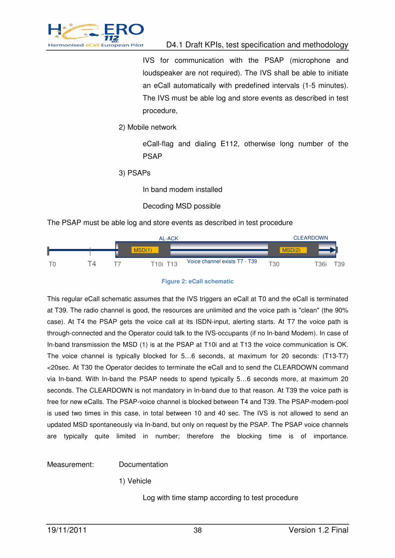
Figure 2: eCall schematic
This regular eCall schematic assumes that the IVS triggers an eCall at T0 and the eCall is terminated
at T39. The radio channel is good, the resources are unlimited and the voice path is "clean" (the 90%
case). At T4 the PSAP gets the voice call at its ISDN-input, alerting starts. At T7 the voice path is
through-connected and the Operator could talk to the IVS-occupants (if no In-band Modem). In case of
In-band transmission the MSD (1) is at the PSAP at T10i and at T13 the voice communication is OK.
The voice channel is typically blocked for 5…6 seconds, at maximum for 20 seconds: (T13-T7)
<20sec. At T30 the Operator decides to terminate the eCall and to send the CLEARDOWN command
via In-band. With In-band the PSAP needs to spend typically 5…6 seconds more, at maximum 20
seconds. The CLEARDOWN is not mandatory in In-band due to that reason. At T39 the voice path is
free for new eCalls. The PSAP-voice channel is blocked between T4 and T39. The PSAP-modem-pool
is used two times in this case, in total between 10 and 40 sec. The IVS is not allowed to send an
updated MSD spontaneously via In-band, but only on request by the PSAP. The PSAP voice channels
are typically quite limited in number; therefore the blocking time is of importance.
Measurement: Documentation
1) Vehicle
Log with time stamp according to test procedure
T0 T4 T7 T10i T13 T30 T36i T39
MSD(1)
AL-ACK CLEARDOWN
MSD(2)
Voice channel exists T7 - T39

D4.1 Draft KPIs, test specification and methodology
05/12/2011 39 Version 1.2 Final
2) Mobile network
Nothing, but the IVS logs several important data about the
mobile network that can be used to understand reasons for
failed eCalls.
3) PSAP
Log with time stamp according to test procedure
4.2.1.6 Test procedure 6:
For: KPI_010: Number of usable satellites
General definition of test procedure: This test collects the number of actually visible GPS
satellites in operation in every particular case of position estimation.
Preconditions: 1) IVS
A GPS receiver is required. Utilization of a SBAS / EGNOS-
enabled or combined GPS+EGNOS / GLONASS receiver is an
advantage.
Access to NMEA data stream using a dedicated application, or
access to internal NMEA stream log is needed.
2) Mobile network
None
3) PSAPs
None
Test procedure: Collect the number of actually visible satellites in operation in every
particular case of position estimation. Number of usable satellites is a
number reported by satellite navigation receiver for every particular
case of position estimation in NMEA-0183 sentences. The record of
the numbers of actually visible satellites is considered the result of the
T&V procedure.

D4.1 Draft KPIs, test specification and methodology
19/11/2011 40 Version 1.2 Final
Measurement: Documentation
1) Vehicle
Internal log of NMEA stream
2) Mobile network
None
3) PSAP
None
4.2.1.7 Test procedure 7:
For: KPI_011: Geometric Dilution of Precision
General definition of test scenario: This test examines the Geometric Dilution of Precision
(GDOP) and refers to the estimate of position estimation error due to spatial distribution of
satellites used for GPS position estimation.
Preconditions: 1) IVS
A GPS receiver is required. Utilization of a SBAS / EGNOS-
enabled or combined GPS+EGNOS / GLONASS receiver is an
advantage.
Access to NMEA data stream using a dedicated application, or
access to internal NMEA stream log is needed.
2) Mobile network
None
3) PSAPs
None
Test procedure: Estimate of position estimation error due to spatial distribution of
satellites used for position estimation. GDOP is a measurable
parameter reported by satellite navigation receiver for every particular
case of position estimation. GDOP observables are reported by GPS
D4.1 Draft KPIs, test specification and methodology
05/12/2011 41 Version 1.2 Final
receiver in the NMEA-0183 sentences. The records of observed
GDOP values are considered the result of the T&V procedure.
Measurement: Documentation
1) Vehicle
Internal log of NMEA stream
2) Mobile network
None
3) PSAP
None
4.2.1.8 Test procedure 8: Time between successful positioning fixes
For: KPI_012: Time between successful positioning fixes
General definition of test scenario: This test refers to the duration of time interval between
two consecutive successful positioning fixes, thus defining the estimation of position
estimation uncertainty at the certain vehicle velocity due to the age of position estimates.
Preconditions: 1) IVS
A GPS receiver is required. Utilization of a SBAS / EGNOS-
enabled or combined GPS+EGNOS / GLONASS receiver is an
advantage.
Access to NMEA data stream using a dedicated application, or
access to internal NMEA stream log is needed.
2) Mobile network
None
3) PSAPs
None
Test procedure: Measure the duration of time interval between two consecutive
successful positioning fixes, thus defining the estimation of position

D4.1 Draft KPIs, test specification and methodology
19/11/2011 42 Version 1.2 Final
estimation uncertainty at the certain vehicle velocity due to the age of
position estimates. The record of time stamps of successful position
estimates is considered the result of the T&V procedure.
Measurement: Documentation
1) Vehicle
Internal log of NMEA stream
2) Mobile network
None
3) PSAP
None
4.2.1.9 Test procedure 9
For: KPI_009: Accuracy of position
KPI_013: Success rate of heading information
The existing eCall standardization calls for the sole utilization of the GPS system for position
estimation. The GPS position determination process comprises the position uncertainty
estimation algorithm that provides a fair estimation of horizontal, vertical and timing error.
Those estimates are available in real-time via standardized NMEA-0183 interface, applied in
modern GPS receivers.
Preconditions: 1) IVS
A GPS receiver is required. Utilization of a SBAS / EGNOS-
enabled or combined GPS+EGNOS / GLONASS receiver is an
advantage.
Access to NMEA data stream using a dedicated application, or
access to internal NMEA stream log is needed.
2) Mobile network
None
3) PSAPs
None
D4.1 Draft KPIs, test specification and methodology
05/12/2011 43 Version 1.2 Final
Test procedure: Position uncertainty estimates (estimates of horizontal GPS positioning
error) reported by GPS receiver via NMEA-0183 sentences at the
regular time intervals (usually every 2 s) are to be recorded, along with
the GPS position estimates reports.
Measurement: Documentation
1) Vehicle
Internal log of NMEA stream
2) Mobile network
None
3) PSAP
Log of MSD content (containing last two positions and heading)
Within the post processing and evaluation process, the correctness of the heading
information will be validated.
4.2.1.10 Test procedure 10
For: KPI_020: Success rate of presented incident data in TMC
General definition of test procedure: It shall be tested, how often the incident data will be
presented successfully within the TMC.
Preconditions: 1) Vehicle
IVS with microphone and loudspeaker for communication with
the PSAP
Possibility to initiate an eCall manually or automatically
2) Mobile network
eCall-flag and dialing E112, otherwise long number of the
PSAP
3) PSAPs
In-band modem installed
Decoding MSD possible
Voice connection possible
Connection to TMC established

D4.1 Draft KPIs, test specification and methodology
19/11/2011 44 Version 1.2 Final
Test sequence: The eCall is initiated at a variety of locations. The locations will be
selected in such a way to reflect different environmental conditions.
Here especially urban canyons, valleys and mountains, or open plain
field should be considered depending on the national geography.
Measurement: Documentation
1) Vehicle
Nothing
2) Mobile network
Nothing
3) PSAP
Log with MSD content presented
Log with incident data sent to TMC
4) TMC
Log with incident data presented at TMC
4.2.1.11 Test procedure 11
For: KPI_021: Number of successful call-backs
KPI_022: Success rate of call-backs
General definition of test procedure: This procedure will test the Call-back function after a call
has been ended by PSAP operator.
Preconditions: 1) Vehicle
IVS with microphone and loudspeaker for communication with
the PSAP
Possibility to initiate an eCall manually or automatically
Possibility to receive call-back
2) Mobile network
eCall-flag and dialing E112, otherwise long number of the
PSAPs.
3) PSAP
Microphone and loudspeaker for communication with the IVS

D4.1 Draft KPIs, test specification and methodology
05/12/2011 45 Version 1.2 Final
MSD decoding capability
Possibility to initiate call-back
Test sequence: Required:
1. IVS initiates an eCall
2. PSAP Operator answers the call and confirms bi-directional voice
connection
3. PSAP Operator hangs up (CLEARDOWN will be sent to the IVS)
4. PSAP operator initiates call-back
5. PSAP Operator confirms bi-directional voice-connection
6. PSAP Operator hangs up again (CLEARDOWN will be sent to the
IVS again)
In the case the call drops before the PSAP Operator will initiate call-
back (step 4) the results of the test will not be taken into consideration
and that call will not be counted as a failed call-back.
Complimentary:
The PSAP Operator will attempt a resend MSD request. This will be
helpful considering that, in case of call-back; the MSD won’t be
transmitted at the beginning of the call.
Measurement: Documentation
1) Vehicle
Internal log
2) Mobile network
Nothing
3) PSAP
Log with indication of bi-directional voice communication both
during the initial call and during call-back
D4.1 Draft KPIs, test specification and methodology
19/11/2011 46 Version 1.2 Final
Note: According to the standards, after the IVS will receive CLEARDOWN from the PSAP it
will remain registered in the network for 60 minutes. In addition to testing the call-back
capability it should be tested that the IVS won’t accept a call-back after this period of time
has passed.
4.2.1.12 Test procedure 12
For: KPI_005: Duration until MSD is presented in PSAP
KPI_007a: Duration of voice channel blocking
KPI_007b: Duration of voice channel blocking: automatic retransmission of MSD
KPI_008: Time for call establishment
KPI_017: Dispatch time of incident data to rescue forces
KPI_018: Time to activate rescue forces
KPI_019: Dispatch time of incident data to TMC
KPI_023: GSM network latency
KPI_024: 112 national network latency
KPI_025: 112 operator reaction time
KPI_026: Time for acknowledgement of emergency services
KPI_027: Total response time
General definition of test procedure: This procedure will allow the measurement of different
time related KPIs.
Preconditions: 1) Vehicle
IVS with microphone and loudspeaker for communication with
the PSAP
Possibility to initiate an eCall manually or automatically
2) Mobile network
none
3) PSAPs
In-Band Modem
MSD decoder
D4.1 Draft KPIs, test specification and methodology
05/12/2011 47 Version 1.2 Final
Microphone and loudspeaker
Possibility to log the events presented in the measurement
section
Possibility to transfer the case to the emergency agencies
Test sequence: Not all the tests will follow the whole sequence and not all the
mentioned KPIs must be measured during one test. Only the first 2
steps are mandatory. All the other steps are required according to the
number of KPIs that will be measured. After the first 2 steps the test
may be stopped at any time.
1) IVS initiates the eCall
2) The eCall travels through the MNO network and national 112
network and reaches the PSAP
3) The eCall is being presented to the operator
4) The operator answers the call
5) The MSD reaches the PSAP
6) The MSD is decoded
7) The MSD is presented to the 112 operator
8) The case is transferred to the emergency agencies
9) The emergency agencies dispatch their resources
10) The resources reach the incident scene
Measurement: Documentation
1) Vehicle
Log with time stamp of eCall initiation (T0-IVS)
Log with start of MSD transmission (T1-IVS)
Log with end of MSD transmission (T2-IVS)
2) Mobile network
Nothing
D4.1 Draft KPIs, test specification and methodology
19/11/2011 48 Version 1.2 Final
3) PSAP
Log with time stamp of eCall indicated at PSAP (T0-PSAP)
Log with time stamp of MSD reception (T1-PSAP)
Log with start of voice transmission (T2-PSAP)
Log with time stamp information dispatch to emergency
services (T3-PSAP)
Log with time stamp information dispatch to TMC (T4-PSAP)
Log with time stamp of eCall entering the national 112 network
Log with time stamp of eCall being answered by the 112
operator
4) Emergency agencies
Log with time stamp of acknowledging the information sent by
the PSAP (T3-ES)
Log with time stamp of dispatching resources to the incident
scene (T4-ES)
Log with time stamp of resources arriving at the incident scene

D4.1 Draft KPIs, test specification and methodology
05/12/2011 49 Version 1.2 Final
4.3 Evaluation of network characteristics
Do get an impression about the quality of the mobile network paths that are used and
especially the behavior of the in-band modem under these conditions, the following KPIs and
test procedures have been defined to evaluate the different characteristics of the network
and their influences on the eCall with in-band modem.
4.3.1 KPI_network_001: Voice channel disturbance
The purpose of this KPI is to evaluate both the eCall standards and the implementation from
a human communication perspective. It is unavoidable that sometimes small parts of the in-
band modem signal will be heard in the loudspeaker / head set at both sides, within the IVS
and within the PSAP. It is unavoidable that the voice path is blocked for some time. Not
optimal implementations may block the voice path in one direction, but not in the other. This
may cause confusion among the communication, as no one can be sure that his/her words
had been heard at the other side. It will be measured during test drives in real networks by a
manually triggered eCall with real voice communication and MSD. Subjective evaluation will
be made by:
a) Driver in the car
b) Operator in the PSAP
It is a subjective evaluation of voice path blockade:
a) due to the PUSH of MSD at call setup (delayed voice call, long muting)
b) especially during PULL of MSD during the call (long voice path blockade, parts of
the modem signal audible)
› Human judgment on a 5 point scale:
– Voice path blockade: 1 (very annoying) - 5 (not noticeable)
– Modem-left-over: 1 (very annoying) - 5 (not noticeable)
– Communication confusion: 1 (very annoying) - 5 (not noticeable)
(Half-duplex communication)
4.3.2 KPI_network_002: Weak radio signal behavior
The purpose of this KPI is to evaluate the behavior of the eCall systems under poor
conditions concerning the mobile network. During drive tests in real networks we may find
weaknesses of the eCall standard and specific implementations but it will be difficult to pin
point the root cause. This KPI is a test under controlled laboratory conditions and will have to

D4.1 Draft KPIs, test specification and methodology
19/11/2011 50 Version 1.2 Final
be preformed according to the means and equipment available in each country (GSM radio
test equipment and set ups). Transmitting eCall over cable with varying attenuation, fading
and interference but with maintained voice call will detect if the eCall standard and its
implementation is correct and where limitations are (regarding radio signal strength,
interferences, retransmissions, time out’s, etc.)
4.3.3 Test procedure: Voice channel disturbance
Due to the nature of In-band Transmission, the Sender of an In-band signal (e.g. IVS) may
block the local audio channels (Microphone and Loudspeaker) immediately when starting
sending. The Receiver of an In-band Signal (e.g. the PSAP) has, however, first to detect the
In-band signal, before it can block its local audio channels. Therefore a short period of the
PUSH signal (termed also “SEND”-burst in 3GPP and “Initiation” in CEN will be audible at
PSAP side in PUSH mode; respectively a short period of the PULL signal (also termed
“START”-burst in 3GPP and “SEND MSD” in CEN will be audible at IVS side in PULL mode.
It depends on implementations skills how much will be audible and how much of the voice
communication is cut out. It should be avoided to open the voice channel in one direction
only (half-duplex communication).
Preconditions: 1) Vehicle
IVS for communication with the PSAP (microphone and
loudspeaker are required). Manual triggered eCalls possible.
2) Mobile network
eCall-flag and dialing E112, otherwise long number of the
PSAP
3) PSAPs
In band modem installed. A skilled PSAP operator takes the
manual eCall according the procedures and has a voice
communication.
Test sequence: Measured during drive tests at different locations to get a reasonable
variation in network signal path and radio conditions. Both PUSH from
the IVS and PULL form the PSAP shall be evaluated. The IVS shall be
able to initiate manual eCalls. Voice communication is established
D4.1 Draft KPIs, test specification and methodology
05/12/2011 51 Version 1.2 Final
between the driver and PSAP operator. Directly after the call the voice
channel disturbance is evaluated.
Measurement: Documentation
Testing people shall fill questionnaires containing value scales with
their feelings about the connection.
4.3.4 Test procedure: Weak radio signal behavior
Preconditions: 1) IVS box for laboratory environment
2) Mobile network
GSM radio channel simulating equipment (depending on local
conditions)
3) PSAPs
A PSAP simulator or a test-PSAP
Test procedure: eCall transmitted (over cable) with bad radio conditions and varying
attenuation /fading of the signal.
eCall transmission (over cable) with bad radio conditions due to
interferences (at high level).
eCall transmission (over cable) with handover conditions.
The same types of test cases that are used for voice channel testing
are applicable.
An analysis of how the system breaks down and recovers at the
sensitivity edge including retransmissions and timeouts shall be
performed.
Target: System shall perform according to the specifications (not get
stuck, but be able to recover)
MSD shall be transmitted when signal conditions are good enough.
System behaviour shall not confuse or disturb involved people.
Evaluation: subjective in a test report.
Here is a list of typical tests that are performed on machine to machine communication
devices and mobile phones, whereas some will be automated and some not. A relevant
subset of these can be tested:
• Test basic function and terminal signalling
o Normal operation test

D4.1 Draft KPIs, test specification and methodology
19/11/2011 52 Version 1.2 Final
o Telenor OTA update
o Deactivated in HLR
o SIM function test
o Coverage loss and return
o Coverage changes
o Power loss and return
• Random attach to the network
• Handover Tests (HO)
o 2G Nokia, Intra MSC, Intra BSC, Intra BTS.
o 2G Nokia, Intra MSC, Intra BSC, Inter BTS.
o 2G Nokia, Intra MSC, Inter BSC, Inter BTS.
o 2G Nokia Inter MSC, Inter BSC, Inter BTS.
• 2G Roaming: MSC2/ BSC KAR2- Roaming MSC, Roaming BSC.
• Congestions Tests
o Blocking, Circuit Switch Traffic (CS). 28
• Sensitivity Tests
• Mobile Sensitivity Test
o Terminal overload test
• Network Error Tests
• Operation stop, BTS.
• Operation stop, BSC.
• Interference Tests
• Channel Interference GSM
• Remote Device management
o Terminal control functions

D4.1 Draft KPIs, test specification and methodology
05/12/2011 53 Version 1.2 Final
5 Annex I – Member States test characteristics
5.1 Croatia
5.1.1 In General
The primary aim of the Croatian eCall Pilot is to test and validate the eCall performance and
operation throughout the eCall chain, from both technological and Standard Operation
Procedures' (SOPs) aspects. The Croatian eCall testing scenarios comprises the following
testing scenario groups:
• eCall components and chain laboratory testing and verification (T&V) scenarios
• eCall communication performance and operation testing and verification (T&V)
scenarios in real network
• eCall SOPs testing and verification (T&V) scenarios
• position estimation for eCall testing and verification (T&V) scenarios
Detailed description of testing scenarios expected to be deployed within the Croatian eCall
Pilot is given in the tables below.

D4.1 Draft KPIs, test specification and methodology
19/11/2011 54 Version 1.2 Final
Figure 3: Croatian test scenarios
5.1.2 Testing environment
The over-all eCall chain will be tested in the ENT eCall laboratory. The necessary pre-
requisite is the full component compliance with the eCall standards. The eCall initiation will
be performed according the particular scenario set-up, as outlined earlier in this document.
All Group 1 KPIs (KPI1 - KPI5) will be measured and observed simultaneously during the
T&V procedure. Measurement procedures for the related KPIs are outlined below. They
apply to planned scenarios L1 - L7.
The overall eCall chain will be tested in real environment, following the scenario
specifications outlined above. The necessary pre-requisite is the full component compliance
with the eCall standards. The eCall initiation will be performed according the particular
scenario set-up, as outlined earlier. All Group 2 KPIs (KPI1 - KPI5) will be measured and
observed simultaneously during the T&V procedure, or post-processed using the records in
the event logs. Measurement procedures for the related KPIs are outlined below. They apply
to planned scenarios R1 - R4.
The eCall SOP will be tested in real environment, following the scenario specifications
outlined earlier in this document. The necessary pre-requisite is the full component
compliance with the eCall standards. The eCall initiation will be performed according the
particular scenario set-up, as outlined earlier in this document. All Group 2 KPIs (KPI1 -
KPI5) will be measured and observed simultaneously during the T&V procedure, or post-

D4.1 Draft KPIs, test specification and methodology
05/12/2011 55 Version 1.2 Final
processed using the records in the event logs. Measurement procedures for the related KPIs
are outlined below. They apply to planned scenarios S1 - S2.
The objective of the position estimation for eCall T&V is to identify the requirements for
position estimation for eCall and to assess GPS positioning performance form the eCall
perspective, regardless of the type of GPS receiver utilised. The intention of this T&V
segment is to objectively assess risks of the sole GPS utilisation, and to propose the
minimum requirements and system integration architecture for the appropriate position
estimation procedure for eCall. In due course, the Group 4 T&V scenarios will be conducted
separately from the rest of the eCall T&V, with utilisation of the GPS receivers of the same
quality levels such as the receivers to be utilised in the eCall IVS. In the first phase of the
eCall Group 4 T&V scenarios performance, GPS, GPS+EGNOS and GPS/GLONASS will be
utilised. In the second phase of the eCall Group 4 T&V scenarios performance, advanced
position estimation methods are to be considered, that call for sensor and system integration.
KPIs values are to be extracted from the NMEA-0183 data stream in the post-processing
procedure after the field work. NMEA-0183 devices usually report the observables in 2
seconds-intervals.
The Croatian eCall Pilot architecture is presented in Figure 4 below.
Figure 4: Croatian eCall pilot architecture
General preconditions for KPI measurements in Croatia
Preconditions: 1) IVS
- Compliance with in-band modem eCall rev 10.0.0 outlined in 3GPP TR 26.969 v
10.0.0 (March 2011) and the other standards and specifications listed in WP2 reports
should be maintained.
- Support for CAN Bus is not required for Group 1, but is an advantage for Group 2.

D4.1 Draft KPIs, test specification and methodology
19/11/2011 56 Version 1.2 Final
- The internal IVS event logger (the application within the IVS that collects time and
description of events involving IVS) with the feature of Internal log content transfer to
PC (preferably via USB) is required. Time synchronization with GPS reference time
frame is required.
- Support for both manual and automatic eCall initiation is required. Manual eCall
initiation should be performed by pushing a dedicated button. Automatic eCall
initiation should be performed as a result of a dedicated algorithmic processing of the
observables of the IVS-embedded accelerometers (MEMS devices), accompanied by
airbag sensor readings (if available).
- SBAS/EGNOS-enabled GPS receiver is required. Utilization of combined
GPS+EGNOS/GLONASS receiver is an advantage.
- The eCall IVS should support fixed-length (140 bytes) eCall MSD messaging.
- Utilization of 2G (GSM/GPRS) SIM card is required. The Croatian eCall Pilot
partners will provide domestic SIM card and SIM card in roaming.
- Power adapter is required, especially for laboratory testing. Utilization of battery +
charger package should be considered, and the necessary accessory should be
provided by the IVS manufacturer. In Group 2 T&V scenarios, a standard cabin 12 V-
socket will be utilized for power supply, for which the necessary accessory should be
provided by IVS manufacturer.
- The eCall IVS unit should be pre-configured for utilization in 2G network by
manufacturer. The Croatian eCall Pilot will provide a specific PSAP telephone
number for pre-configuration, for Group 1 T&V. Standard 112 number is to be pre-
configured for Groups 2 and 3 T&V.
2) Mobile network
- Croatian eCall Pilot will assess the eCall performance through utilization of Ericsson
PLMN equipment. Laboratory T&V will be conducted on Ericsson PLMN equipment
pre-configured in order to emulate existing Croatian eCall Pilot MNO partners'
environment, with the addition of the eCall flag support, in accordance with related
eCall-related CEN, ETSI and 3GPP standards listed in WP2 report.
3) PSAPs
- The PSAP system should support the PSAP eCall modem communication
according to relevant CEN, ETSI and 3GPP standards listed in WP2 report, and in
particular the latest revisions of: ISO/EN 24978:2009, CEN WI 00278243, CEN WI

D4.1 Draft KPIs, test specification and methodology
05/12/2011 57 Version 1.2 Final
00278220, CEN TS 15722, 3GPP TS 22.101, 3GPP TS 24.008, 3GPP TS 26.267,
3GPP TS 26.268, 3GPP TS 26.269, 3GPP TS 26.969.
- A dedicated landline phone number, reachable through international call, should be
provided.
- Minimum Set of Data (MSD) parsing application should be provided, based on the
standards listed in WP2 report, and in particular the latest revisions of: ISO/EN
24978:2009, CEN WI 00278243, CEN WI 00278220, CEN TS 15722, 3GPP TS
22.101, 3GPP TS 24.008, 3GPP TS 26.267, 3GPP TS 26.268, 3GPP TS 26.269,
3GPP TS 26.969.
- Call and data PSAP event internal log feature should be deployed and operational.
The PSAP event Internal log should record the following parameters: unique call ID,
caller MSISDN number, call data, call time, modem session duration, total call
duration, data received flag (1 = received, 0 = not received), non-parsed content of
received MSD. A web-based application should be deployed t display and transfer the
PSAP event log.
- PSAP should support an activity monitor feature, under which the following
parameters should be displayed if activity monitoring is requested by user: unique call
ID, caller MSISDN number, connection status, data transfer/reception status, modem
session duration, total call duration, (parsed) MSD content, map with position
indication.
- PSAP should support a internal log browser feature, under which a user can request
to browse the Internal log for a pre-selected time period, and after that to be
presented with the list of the following parameters: unique call ID, caller MSISDN
number, call date, call time, modem session duration, total call duration, data
received flag (1 = received, 0 = not received).
- PSAP should support a data parser feature, to be invoked by selection of a line from
one line in the list provided by internal log browser feature. Using data parser feature,
a user can request to display the contents of selected line of the Internal log record,
and after that to be presented with the list of the following parameters: unique call ID,
caller MSISDN number, call date, call time, modem session duration, total call
duration, data received flag (1 = received, 0 = not received), (parsed) MSD contents.

D4.1 Draft KPIs, test specification and methodology
19/11/2011 58 Version 1.2 Final
- PSAP should maintain time-frame synchronization using GPS, or (optionally) a
dedicated atomic clock web-based time synchronization service (such as NIST
Internet Time Synchronization, available at: http://1.usa.gov/9vR3Tc).
5.1.3 Country specific matters in Croatia
Country specific matters are already described in the paragraphs before.

D4.1 Draft KPIs, test specification and methodology
05/12/2011 59 Version 1.2 Final
5.2 Czech Republic
5.2.1 In General
The goal of testing and validation of eCall system in the Czech Republic is to validate
technological and functional properties of the system. Testing is divided into 2 parts:
• Laboratory testing
• Testing in real environment
For laboratory testing there will be used GNSS Simulator Spirent GSS 8000 where there is
possible to set up properties and simulate limit conditions which are not possible to achieve
in real environment. The limit conditions are predicted in eCall system operations so this
approach is very important.
As a second step after laboratory testing there will be performed tests in real environment to
validate correct functionality and technology readiness of the eCall system.
5.2.2 Testing environment
Tests will be performed based on test scenarios for the cases described in table 3.
5.2.3 IVS testing
IVS testing will follow requirements based on ISO 16062 Intelligent transport systems -
eSafety - eCall high level application requirements (HLAP).
Conformance points for the in-vehicle system:
• Activation of pan-European eCall
• Call set-up
• MSD transfer
• Application layer ACK
• No receipt of application ACK
• Request “Send MSD”
• Check audio link to vehicle occupants
• Call clear-down
• eCall session termination
• PSAP Call back

D4.1 Draft KPIs, test specification and methodology
19/11/2011 60 Version 1.2 Final
• MSD not transmitted correctly
• PSAP modem failure before link layer LLACK is sent
• PSAP modem failure after link layer LLACK is sent
• IVS does not receive a clear-down
5.2.4 Test purpose for the IVS
• To verify that the eCall equipped IVS has the capability to be initiated via an external
interface with the fix data values required for the building of the MSD.
• To verify that upon vehicle ignition, the IVS has the capability to achieve some self
test and be ready to start an eCall session in both test and operating mode.
• To verify that the eCall equipped IVS has the capability to react appropriately
according to whether it is in operating mode or test.
• To verify that the eCall equipped IVS has the capability to start an eCall session in
conformity to EN 16072.
• To verify that the eCall equipped IVS has the capability to generate a well formatted
MSD in conformity to EN 15722.
• To verify that the eCall equipped IVS has the capability to initiate an E112 call with its
associated relevant flags.
• To verify that the eCall equipped IVS has the capability to disconnect its microphone
and loudspeaker from the telephone line and send the formatted MSD to the PSAP
when the 112 link is established.
• To verify that the eCall equipped IVS has the capability to send the latest MSD
version under a PSAP request during any phase of an eCall session.
• To verify that the eCall equipped IVS has the capability to connect its microphone and
loudspeaker to the telephone line and maintain an audio call with the PSAP as soon
as a MSD application layer acknowledgement has been received.
• To verify that the eCall equipped IVS has the capability to terminate the 112 link when
receiving a clear-down indication from the PSAP.
• To verify that the eCall equipped IVS has the capability to terminate an eCall session
after T9 (IVS NAD minimum network registration period) following the last received
clear-down from the PSAP.
• To verify that, following the reception of a PSAP call back, the IVS has the capability
to reconnect its audio equipment to the line and ensure audio exchange between
vehicle occupants and PSAP/Rescue team operator.
• To verify that the IVS has the capability to recover in case of a call clear-down failure.
• To verify that the IVS has the capability to switch to TS12 mode in case of non eCall
equipped PSAP or PSAP failure.

D4.1 Draft KPIs, test specification and methodology
05/12/2011 61 Version 1.2 Final
5.2.5 Selection of conformance points for the PSAP equipment
• E112 call management
• Cell position and caller ID presentation
• Test call received
• Received MSD management
• PSAP operator HMI
• Audio exchange
• Calling back the vehicle
• Request send MSD
• PSAP call clear-down
• PSAP unable to receive MSD
5.2.6 Test purpose for the PSAP equipment
• To verify that the eCall equipped PSAP application layer has the capability to receive
an MSD, decode it, check its error free and verify its conformity to EN 15722.
• To verify that the PSAP application layer has the capability to display the MSD
content and some other elements, e.g. caller ID, cell position, decoded VIN to the
PSAP operator as required.
• To verify that the eCall equipped PSAP application layer has the capability to
automatically request to its link layer the transmission of an “AL-ACK” response to the
IVS.
• To verify that the eCall equipped PSAP application layer has the capability to request
its link layer to transmit a “Send MSD” request to the IVS at any time during the eCall
session.
• To verify that the eCall equipped PSAP application layer has the capability to request
its link layer to transmit a “clear-down” request to the IVS at any time after the
reception of an MSD while the E112 call stays present.
• To verify that the eCall equipped PSAP application layer has the capability to connect
the audio system of the PSAP operator to the receiving line. Then verify that a bi-
directional audio communication is achievable between the PSAP operator and the
vehicle occupants.
• To verify that the eCall equipped PSAP application layer is behaving as expected
when receiving a test call, e.g. generating a “clear-down” request to its link layer or
forwarding the call to a test PSAP.
• To verify that the eCall equipped PSAP application layer has the capability to send a
“call back” request to its link layer for the purpose of re-establishing an audio liaison
between the PSAP operator / rescue team and the occupants of the vehicle (RPSAP
09).
• To verify that the eCall equipped PSAP application layer has the capability to request a new MSD.

D4.1 Draft KPIs, test specification and methodology
19/11/2011 62 Version 1.2 Final
5.2.7 Test environment description
5.2.7.1 Laboratory
Figure 5: Czech laboratory configuration
5.2.7.2 Real environment
Figure 6: Real environment configuration

D4.1 Draft KPIs, test specification and methodology
05/12/2011 63 Version 1.2 Final
5.2.8 GNSS simulator
It is possible to use laboratory testing of GNSS part of HeERO project, although this
laboratory does not cover part for GSM communication.
The core function of the laboratory testing is the ability to simulate the GNSS signals as
inputs for testing ITS applications to be aware of all the entry conditions and low system
parameters and ITS applications could be statistically validated on a sufficient number of
measurements.
Figure 7: GNSS simulator
Czech consortium could use the GNSS Simulator Spirent GSS 8000. Its main advantage is
the ability to simulate up to 10 satellites simultaneously and simulate the GNSS-defined
route. In addition, GNSS signals can be simulated in many ways to model and simulate the
boundary conditions. This includes the following parameters, which can be modeled:
• Satellite distribution - in a different constellation of GNSS satellites for various time periods (based on almanac file);
• Satellites transmission power;
• Multipath signal reception (multipath);
• Signal ground reflection;
• Signal obscuration;
• Atmospheric effects on signal;
• The impact of receiver antenna (model) - various parameters of the antenna, different antenna positions in the vehicle, or more antennas, etc;
• Vehicle parameters - the maximum speed, maximum acceleration, maximum angular velocity, maximum angular acceleration, etc.;
• Vehicle sensors inputs modeling.

19/11/2011
5.2.8.1 Satellite distribution
Precision positioning using GNSS techn
measurements the one hand and the geometric configuration of the available satellites on
the other hand. Integer value is called DOP (Dilution of Precision, accuracy variance). There
are used a few sub-DOP parameters:
• GDOP: Geometric DOP (position in spac
• PDOP: Spatial DOP (position in space);
• HDOP: Horizontal DOP (position in the horizontal component);
• VDOP: Vertical DOP (vertical component of position);
• TDOP: Time DOP (time accuracy).
When visible satellites are close together in
value is high. When the satellites are far apart, the geometry is strong and the DOP value is
low. Low DOP value represents the greater accuracy of position.
Figure 8: Geometric configu
Value of the HDOP varies with geographic location only a little, VDOP value is changing a lot
with geographic latitude. The latitude of ± 56 ° VDOP reaches its minimum and with latitude
increasing VDOP significantly
fact that after crossing the latitude, which is equal to the track inclination, already below the
overhead satellites, culminating in increasingly lower elevations. Three
positioning error almost follows track of the dominant height error.
D4.1 Draft KPIs, test specification and methodology
64
Satellite distribution
Precision positioning using GNSS technology depends on the accuracy of
measurements the one hand and the geometric configuration of the available satellites on
the other hand. Integer value is called DOP (Dilution of Precision, accuracy variance). There
DOP parameters:
GDOP: Geometric DOP (position in space, including time-shift);
PDOP: Spatial DOP (position in space);
HDOP: Horizontal DOP (position in the horizontal component);
VDOP: Vertical DOP (vertical component of position);
TDOP: Time DOP (time accuracy).
When visible satellites are close together in the sky, the geometry is weak and the DOP
value is high. When the satellites are far apart, the geometry is strong and the DOP value is
low. Low DOP value represents the greater accuracy of position.
: Geometric configuration of the GNSS satellites
Value of the HDOP varies with geographic location only a little, VDOP value is changing a lot
with geographic latitude. The latitude of ± 56 ° VDOP reaches its minimum and with latitude
increasing VDOP significantly increases. This error increase at higher latitudes is due to the
fact that after crossing the latitude, which is equal to the track inclination, already below the
overhead satellites, culminating in increasingly lower elevations. Three
ing error almost follows track of the dominant height error.
Draft KPIs, test specification and methodology
Version 1.2 Final
ology depends on the accuracy of pseudo-range
measurements the one hand and the geometric configuration of the available satellites on
the other hand. Integer value is called DOP (Dilution of Precision, accuracy variance). There
the sky, the geometry is weak and the DOP
value is high. When the satellites are far apart, the geometry is strong and the DOP value is
Value of the HDOP varies with geographic location only a little, VDOP value is changing a lot
with geographic latitude. The latitude of ± 56 ° VDOP reaches its minimum and with latitude
increases. This error increase at higher latitudes is due to the
fact that after crossing the latitude, which is equal to the track inclination, already below the
overhead satellites, culminating in increasingly lower elevations. Three-dimensional

D4.1 Draft KPIs, test specification and methodology
05/12/2011
Figure 9
Using simulation tools there is possible to model various geometric distribution of satellites
typical example for different latitudes. There is possible to simulate conditions of high and
low levels of DOP indicators. For each of the satellites there is possible to simulate the signal
level, or to switch off the satellite which leads to a situation of broadcast only
combination of these settings allows assembling many different test scenarios for testing
GNSS signal reception, depending on the constellation of satellites.
Figure
Figure 11
Draft KPIs, test specification and methodology
65
9: Satellites position and movement over time
Using simulation tools there is possible to model various geometric distribution of satellites
different latitudes. There is possible to simulate conditions of high and
low levels of DOP indicators. For each of the satellites there is possible to simulate the signal
level, or to switch off the satellite which leads to a situation of broadcast only
combination of these settings allows assembling many different test scenarios for testing
GNSS signal reception, depending on the constellation of satellites.
Figure 10: Display of received signal levels
11: Display of setting concerning signal levels
Version 1.2 Final
Using simulation tools there is possible to model various geometric distribution of satellites
different latitudes. There is possible to simulate conditions of high and
low levels of DOP indicators. For each of the satellites there is possible to simulate the signal
level, or to switch off the satellite which leads to a situation of broadcast only n satellites. The
combination of these settings allows assembling many different test scenarios for testing

D4.1 Draft KPIs, test specification and methodology
19/11/2011 66 Version 1.2 Final
This feature can also be used to simulate a particular constellation of GNSS satellites in the
defined period of time in the past. This includes re-induction (replay) of the situation that
leads to the application or device error. This is possible for the GPS signal, which is
governed by the so-called GPS weeks. For each GPS week almanac generated file that
defines the current position of the GPS satellites. This information is freely available in the
internet. This file is imported into the simulation software tools and the position of the satellite
after that corresponds to the required time.
5.2.8.2 GNSS signal emulation
Process through the generation of GNSS signal in the simulator is processed in several
steps (and is shown on the picture below):
Operator in the simulation program sets the course route (manually or pre-prepared set of
positional data, such as NMEA data) and all parameters of the generated signal (e.g. number
of available satellites, their output level, a constellation of satellites, signal reflections, near
ground relief, etc. - the parameters are defined below), depending on the kind of test.
Proprietary data is sent to the GNSS signal generator which generates a defined signal and
this is broadcasted into the environment via antenna.
Test equipment with the application is located within range of the generated signal and the
personal device / application is tested.
Data recorded during the tests will be analyzed later on (e.g. comparing the log of the NMEA
in Simulator and NMEA log recorded in the test equipment).
Figure 12: Testing scheme

D4.1 Draft KPIs, test specification and methodology
05/12/2011
5.2.8.3 Error test conditions simulation
Simulation technology allows simulate signal induced error conditions that may occur in real
situations and also absolutely unrealistic situation. Based on the simulated signal with
defined error conditions GNSS devices and applications are tested to verif
For example this scenario verifies that navigation device in the vehicle which does not
receive any GNSS signal already using only data from sensors in the vehicle.
5.2.8.3.1 Multipath signal reception
Multipath is the effect of influencing the ac
the satellite signal is reflected from buildings or other obstacles, including land and water.
Reflections coming into the receiver traveled a greater distance from the satellite for a longer
time. This influence pseudo range determination and thus the exact position.
The problem of multipath signal reception occurs mainly in the so
Illustration can be seen in Figure
Draft KPIs, test specification and methodology
67
Error test conditions simulation
Simulation technology allows simulate signal induced error conditions that may occur in real
situations and also absolutely unrealistic situation. Based on the simulated signal with
defined error conditions GNSS devices and applications are tested to verif
For example this scenario verifies that navigation device in the vehicle which does not
receive any GNSS signal already using only data from sensors in the vehicle.
Multipath signal reception
Multipath is the effect of influencing the accuracy of positioning using GNSS. It is a fact that
the satellite signal is reflected from buildings or other obstacles, including land and water.
Reflections coming into the receiver traveled a greater distance from the satellite for a longer
nfluence pseudo range determination and thus the exact position.
The problem of multipath signal reception occurs mainly in the so-called urban canyons.
ure 13.
Figure 13: Multipath scenario
Version 1.2 Final
Simulation technology allows simulate signal induced error conditions that may occur in real
situations and also absolutely unrealistic situation. Based on the simulated signal with
defined error conditions GNSS devices and applications are tested to verify their response.
For example this scenario verifies that navigation device in the vehicle which does not
receive any GNSS signal already using only data from sensors in the vehicle.
curacy of positioning using GNSS. It is a fact that
the satellite signal is reflected from buildings or other obstacles, including land and water.
Reflections coming into the receiver traveled a greater distance from the satellite for a longer
nfluence pseudo range determination and thus the exact position.
called urban canyons.

D4.1 Draft KPIs, test specification and methodology
19/11/2011 68 Version 1.2 Final
Figure 14: Multipath signal reception
The receiver has no way to distinguish incoming signals and, therefore, considers all the
resulting signals together. To reduce the inaccuracies is the better design of the antenna.
Some advanced receivers solve multipath by making use of only the first detected signal
(which is considered to be one that spreads directly from satellite), then any delayed signals
involved.
Using simulation tools to model for any multipath signals independently of their distribution
(i.e. separately). There can be set the signal spread in the direct line of sight, or without. For
each such signal there can be determined the level of the reflected signal, and possibly
influence the signal on a sufficient channel. The reflections can also set the parameters for
the Doppler signal shift, the phase signal shift, the signal points of the receiver antenna, and
more detailed parameters.
Figure 15: Manual multipath settings

D4.1 Draft KPIs, test specification and methodology
05/12/2011
5.2.8.3.2 Ground reflection
As already mentioned in the multipath, the signal reflections may occur from the ground or
from water. Ground reflection is one of the types of multipath propagation of signals. The
following picture is suggested by the principle of such reflection.
Antenna located at a certain height, also receives the signals reflected from the ground,
assuming that the ground is flat. The receiver then receives multiple signals from the line of
sight, which leads to inaccuracies in determining the exact position.
Using simulation tools allows creating simulations of ground reflections. Here you can set the
level of each signal and its influence on a particular channel.
5.2.8.3.3 Obscuration
Obscuration is a phenomenon where the direct signal from the satellite is shielded by an
obstruction, or when a narrowed view of the available satellites. The receiver will only receive
signals from satellites above a certain cut
Draft KPIs, test specification and methodology
69
already mentioned in the multipath, the signal reflections may occur from the ground or
from water. Ground reflection is one of the types of multipath propagation of signals. The
following picture is suggested by the principle of such reflection.
Figure 16: Ground reflection principle
Antenna located at a certain height, also receives the signals reflected from the ground,
assuming that the ground is flat. The receiver then receives multiple signals from the line of
leads to inaccuracies in determining the exact position.
Using simulation tools allows creating simulations of ground reflections. Here you can set the
level of each signal and its influence on a particular channel.
Figure 17: Ground reflection settings
Obscuration is a phenomenon where the direct signal from the satellite is shielded by an
obstruction, or when a narrowed view of the available satellites. The receiver will only receive
a certain cut-off angle.
Version 1.2 Final
already mentioned in the multipath, the signal reflections may occur from the ground or
from water. Ground reflection is one of the types of multipath propagation of signals. The
Antenna located at a certain height, also receives the signals reflected from the ground,
assuming that the ground is flat. The receiver then receives multiple signals from the line of
Using simulation tools allows creating simulations of ground reflections. Here you can set the
Obscuration is a phenomenon where the direct signal from the satellite is shielded by an
obstruction, or when a narrowed view of the available satellites. The receiver will only receive

19/11/2011
Sources of geographic obscuration
Sources of local obscuration are
Using simulation tools allows modeling various types of obstacles to obscure signal. Ground
obstacles can be modeled as high buildings, trees or bridges. There can be also modeled as
well as geographic objects in
canyons, etc. Each set of objects can be modeled fairly in detailed editor, including the length
of the obstacles, the height and location of the simulated route. Objects can be grouped into
different scenarios for easy reuse.
5.2.8.3.4 Atmosphere models
While passing the GNSS signals through the atmosphere there are generated relatively large
inaccuracies in determining position. Ionospheric and tropospheric errors are caused by
changes in velocity of propagation through the atmosphere. Ionospheric refraction can be
eliminated by measuring at two frequencies, because the passage of the signal through
ionosphere is frequency-dependent. Passing GNSS signals through the troposphere
resulting signal variations due to changes in temperature, pressure and humidity.
D4.1 Draft KPIs, test specification and methodology
70
Figure 18: GNSS signal obscuration I
Sources of geographic obscuration are i.e. mountains and buildings.
Sources of local obscuration are i.e. aircrafts, trees or other effects.
Figure 19: GNSS signal obscuration II
Using simulation tools allows modeling various types of obstacles to obscure signal. Ground
obstacles can be modeled as high buildings, trees or bridges. There can be also modeled as
well as geographic objects interfering with the signal, such as hills, mountains, valleys,
canyons, etc. Each set of objects can be modeled fairly in detailed editor, including the length
of the obstacles, the height and location of the simulated route. Objects can be grouped into
ferent scenarios for easy reuse.
Atmosphere models
While passing the GNSS signals through the atmosphere there are generated relatively large
inaccuracies in determining position. Ionospheric and tropospheric errors are caused by
pagation through the atmosphere. Ionospheric refraction can be
eliminated by measuring at two frequencies, because the passage of the signal through
dependent. Passing GNSS signals through the troposphere
due to changes in temperature, pressure and humidity.
Draft KPIs, test specification and methodology
Version 1.2 Final
Using simulation tools allows modeling various types of obstacles to obscure signal. Ground
obstacles can be modeled as high buildings, trees or bridges. There can be also modeled as
terfering with the signal, such as hills, mountains, valleys,
canyons, etc. Each set of objects can be modeled fairly in detailed editor, including the length
of the obstacles, the height and location of the simulated route. Objects can be grouped into
While passing the GNSS signals through the atmosphere there are generated relatively large
inaccuracies in determining position. Ionospheric and tropospheric errors are caused by
pagation through the atmosphere. Ionospheric refraction can be
eliminated by measuring at two frequencies, because the passage of the signal through
dependent. Passing GNSS signals through the troposphere
due to changes in temperature, pressure and humidity.

D4.1 Draft KPIs, test specification and methodology
05/12/2011
Figure
Tropospheric and ionospheric refraction can be modeled quite accurately and in detail. There
can be set different widths for
different rates of dry gas, which reflects the signal or can modify humidity and other
parameters.
It must be said; however, that simulation of these effects on the signal is very complex and
requires a fairly deep knowledge of the subject. Currently, this method of influencing the
GNSS signal is not widely used.
5.2.8.3.5 Receiver antenna influence
Receiver antenna also has an impact on the overall positioning. Among its features include
gain, directivity and the possibility of phase measurements. If there is used a surveying
instrument with precision antennas, with the phase measurement with a larger number of
channels, etc., we get more accurate results than using an ordinary low
receivers.
Simulation allows us to set the exact parameters of the antenna for a particular type allows
modeling of different obstacles in the signal path (e.g. the roof of the vehicle, etc.). We can
also make simulations for multiple antennas to one receiver.
Fi
Draft KPIs, test specification and methodology
71
Figure 20: GNSS signal path hemisphere
Tropospheric and ionospheric refraction can be modeled quite accurately and in detail. There
can be set different widths for different layers of satellite position, there can be also set
different rates of dry gas, which reflects the signal or can modify humidity and other
however, that simulation of these effects on the signal is very complex and
quires a fairly deep knowledge of the subject. Currently, this method of influencing the
GNSS signal is not widely used.
Receiver antenna influence
Receiver antenna also has an impact on the overall positioning. Among its features include
and the possibility of phase measurements. If there is used a surveying
instrument with precision antennas, with the phase measurement with a larger number of
channels, etc., we get more accurate results than using an ordinary low
Simulation allows us to set the exact parameters of the antenna for a particular type allows
modeling of different obstacles in the signal path (e.g. the roof of the vehicle, etc.). We can
also make simulations for multiple antennas to one receiver.
Figure 21: Reception in a vehicle antenna
Version 1.2 Final
Tropospheric and ionospheric refraction can be modeled quite accurately and in detail. There
different layers of satellite position, there can be also set
different rates of dry gas, which reflects the signal or can modify humidity and other
however, that simulation of these effects on the signal is very complex and
quires a fairly deep knowledge of the subject. Currently, this method of influencing the
Receiver antenna also has an impact on the overall positioning. Among its features include
and the possibility of phase measurements. If there is used a surveying
instrument with precision antennas, with the phase measurement with a larger number of
channels, etc., we get more accurate results than using an ordinary low-cost handheld
Simulation allows us to set the exact parameters of the antenna for a particular type allows
modeling of different obstacles in the signal path (e.g. the roof of the vehicle, etc.). We can

D4.1 Draft KPIs, test specification and methodology
19/11/2011 72 Version 1.2 Final
For the precise parameters of the antenna there is available a 3D modeling environment that
enables to set the parameters according to the actual antenna radiation patterns.
Figure 22: Antenna model I
Figure 23: Antenna model II
5.2.8.3.6 Vehicle parameters
For each modeled vehicle there can be defined the characteristics and dynamics. Movement
of vehicles can be restricted according to different personal profiles. Limits can be specified
to represent special examples. So there are possible to model aircraft (such as Boeing 747)
or a road vehicle (small vehicle or F1).

D4.1 Draft KPIs, test specification and methodology
05/12/2011
Figure
5.2.8.3.7 Vehicle sensors
With hardware and simulation tools there is possible to model parameters except the
parameters of GNSS also sensors in the vehicle, such as gyroscope, speedometer, wheel
speed sensors, temperature sensors, etc. These sensors can be set in
with the setting parameters and testing of GNSS signals and receiving equipment (e.g.
dynamic navigation, which uses input data from sensors in the car) on the one hand and the
behavior modification in the event of a vehicle's interna
combinations on the other hand.
Signals from sensors in the vehicle are then transmitted via 4 analog and 8 digital outputs
that can be connected to the receiver (or to the rotate table, which simulates the movement
of the vehicle).
5.2.9 Country specific matters in Czech Republic
Country specific matters are already described in the paragraphs before.
Draft KPIs, test specification and methodology
73
Figure 24: Moving objects profile settings
With hardware and simulation tools there is possible to model parameters except the
parameters of GNSS also sensors in the vehicle, such as gyroscope, speedometer, wheel
speed sensors, temperature sensors, etc. These sensors can be set in detail in cooperation
with the setting parameters and testing of GNSS signals and receiving equipment (e.g.
dynamic navigation, which uses input data from sensors in the car) on the one hand and the
behavior modification in the event of a vehicle's internal sensors and their possible
combinations on the other hand.
Signals from sensors in the vehicle are then transmitted via 4 analog and 8 digital outputs
that can be connected to the receiver (or to the rotate table, which simulates the movement
Figure 25: Sensor model
Country specific matters in Czech Republic
Country specific matters are already described in the paragraphs before.
Version 1.2 Final
With hardware and simulation tools there is possible to model parameters except the
parameters of GNSS also sensors in the vehicle, such as gyroscope, speedometer, wheel
detail in cooperation
with the setting parameters and testing of GNSS signals and receiving equipment (e.g.
dynamic navigation, which uses input data from sensors in the car) on the one hand and the
l sensors and their possible
Signals from sensors in the vehicle are then transmitted via 4 analog and 8 digital outputs
that can be connected to the receiver (or to the rotate table, which simulates the movement

D4.1 Draft KPIs, test specification and methodology
19/11/2011 74 Version 1.2 Final
5.3 Finland
The goal of testing and validation of eCall system in Finland is to validate technological and
functional properties of the system. The testing environment to be implemented will cover the
whole service chain from the eCall IVS to a simulated PSAP. Cross-border tests to be carried
out in Finland will be very similar to tests carried out in the Finnish eCall pilot.
5.3.1 In General
The following figure outlines the HeERO Finnish pilot system to be implemented, and its
basic components (see D2.3 Finnish pilot implementation plan).
Figure 26: HeERO Finnish pilot system architecture outline
The main parts of the system include:
• eCall client simulator (eCall IVS)
• PSAP simulator, which consists of eCall test bed system, PSAP1 service and PSAP2 test system.
• eCall pilot system control and administrator’s UI.
eCall IVS
Software
modem
GPS
User interfaceMessage activation and configuration
eCall client simulatorPSAP
PSAP1
PSAP2
eCall testbed
Software
modemMSD
encodingMSD
extraction, decoding,
validation
Voice + MSD
ELS
ELS SOAP API
ELS
ELS SOAP API
Risk assessment by a human user
PSAP2 API
MSD handling,data complementing
and verification
PSAP1 API
call to test number
https
eCall testbed control UI
Control and configuration
Show result logs
www.ecall.fi/xyzwww.ecall.fi/xyz
Logs, configurations
PSAP2
PSAP simulator
Control and administrator’s UI

D4.1 Draft KPIs, test specification and methodology
05/12/2011 75 Version 1.2 Final
5.3.1.1 eCall client simulator (IVS)
The eCall client (IVS) simulator to be implemented will include functionality for generating
and combining eCall message data content, encoding the message data for data transfer,
opening phone call and using in-band modem for sending eCall messages.
It will include a user interface for configuring and generating MSD (Minimum Set of Data)
messages.
The generated MSD data will be encoded for the data transfer according to the standard
CEN EN 15722 (eCall minimum set of data).
The client will use the eCall standardized in-band modem data transfer for sending
messages.
The messages (opened voice call) are targeted to the configured phone number of the eCall
receiver side (PSAP simulator). For testing purposes, the number is other than 112.
5.3.1.2 PSAP simulator
The PSAP simulator part of the system will consists of eCall test bed, PSAP1 service and
PSAP2 test system. These components together constitute the eCall pilot system eCall
message receiver side.
5.3.1.3 eCall test bed
The eCall test bed is the eCall message receiver part of the system. It includes functionality
for handling incoming eCall phone calls. It receives and decodes eCall message data,
includes interfaces for PSAP1 and PSAP2 subsystems, provides logs for analyzing results
and includes facility for configuring the operation of the system.
A test phone number (other than 112) is configured for test bed to receive eCall phone calls.
The test bed uses the standardized in-band modem to extract eCall data from the call.
The incoming MSD messages are assumed to be encoded according to the standard CEN
EN 15722 (eCall minimum set of data). The test bed decodes and validates MSD messages.
For analyzing results, there will be a log facility included into the system. It will provide
information about received messages and error cases. In particular, it will be used to validate
the operation of the system as well as eCall clients. The report “D2.4 System test cases and
verification report” will later specify the system verification scenarios. The logs generated by
the test bed have a particular importance in validation of the system operation.
D4.1 Draft KPIs, test specification and methodology
19/11/2011 76 Version 1.2 Final
5.3.2 Testing environment
5.3.2.1 Test scenario 1: Successful eCall
This is the main test scenario of the Finnish eCall pilot. This test scenario will cover the
following KPIs: 1a, 1b, 2, 3, 4, 5, 6, 7, 8 and 9.
Preconditions: 1) Vehicle
IVS with microphone and loudspeaker for communication with the
PSAP.
Possibility to initiate an eCall manually.
Possibility to configure VIN to be transmitted to PSAP.
eCall client simulator will be used in tests as an IVS.
2) Mobile network
GSM or UMTS mobile network, call to an ordinary E.164 phone
number used for testing purposes.
3) PSAPs
3GPP modem installed
Decoding and visualisation of MSD possible
Voice connection possible
System used to receive eCalls in the Finnish eCall pilot consists of an
eCall test bed connected to ELS (PSAP information system, see figure
26 and chapter 5.3.1.3 for detailed descriptions of the PSAP side
infrastructure).
Test procedure: eCall is initiated manually at a variety of locations. The locations will be
selected in such a way to reflect different environmental conditions.
Tests will be carried out at least two types of locations: densely built
urban area and on a main road outside city centre. From 20 to 50 test
calls are expected to be initiated.
eCall is received by eCall test bed connected to ELS. Data logging on
the PSAP side will be performed automatically by the eCall test bed
and manually by a human user. A human user will answer the calls at

D4.1 Draft KPIs, test specification and methodology
05/12/2011 77 Version 1.2 Final
the PSAP side, record the point in time when the contents of the MSD
are presented and verify the status of the voice connection.
Measurement: Documentation
1) Vehicle
Log file collected by the eCall client simulator used as an IVS.
The log file will contain information about various types of events
such as activation of the IVS, opening of the GSM call to a test
number, beginning of the transmission of MSD, end of the
transmission of MSD and end of eCall. Information available about
each documented event will include at least the type of event and
time stamp.
An ordinary E.164 phone number will be used for testing of eCall
instead of emergency number 112.
2) Mobile network
No data logging is performed by the mobile network.
3) PSAP
The PSAP simulator used to receive the test calls will collect log
files about various events related to incoming test calls. At least the
following events will be logged by the PSAP simulator for each test
call:
- opening of test call
- start of MSD transmission
- end of MSD transmission (transmission of link or application layer
ACK)
- voice channel established
- closing of test call
Information about an event will include the type of event,
timestamp and possible supplementary data such as contents of
the MSD.

D4.1 Draft KPIs, test specification and methodology
19/11/2011 78 Version 1.2 Final
A human user will answer the test calls at the PSAP used for
testing and record the point in time when the contents of the MSD
is presented, status of the voice connection and results of VIN
decoding.
eCall testing during the pilot will be accomplished as illustrated in the following figure:
Figure 27: Pilot eCall testing in Finland
In addition to the eCall client simulator several other eCall clients may be used during the
pilot. They may include both eCall client simulators and/or in-vehicle clients (if available).
The clients used should include functionality for generating and sending standard eCall MSD
(Minimum Set of Data) messages via the standardized in-band modem solution to the test
number configured to the PSAP simulator (eCall test bed)
During the tests, a Web user interface for managing the operation of the test bed will be used
(see Figure 27). It will provide configurations for the test users, possibility to register the eCall
clients (e.g. client phone numbers) used in the tests. Also, the pilot system operation can be
managed via the user interface. It will also provide views to result logs.
The log facility of the test bed will provide information about received messages (e.g. call
time, modem session, duration, MSD information, warnings) and error cases. In particular, it
will be used to validate the operation of the system as well as eCall clients.
eCall IVS
eCall client simulator ordevice prototype
Voice + MSD
call to test number
https
www.ecall.fi/xyzwww.ecall.fi/xyz
eCall testbed
PSAP2 API
PSAP1 API
PSAP simulator
Control (Web) UI for eCall testbed
Configuration, logs
• test users• configuration
• result logs
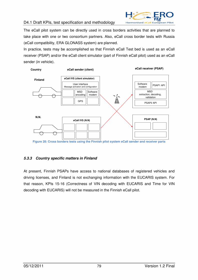
D4.1 Draft KPIs, test specification and methodology
05/12/2011 79 Version 1.2 Final
The eCall pilot system can be directly used in cross borders activities that are planned to
take place with one or two consortium partners. Also, eCall cross border tests with Russia
(eCall compatibility, ERA GLONASS system) are planned.
In practice, tests may be accomplished so that Finnish eCall Test bed is used as an eCall
receiver (PSAP) and/or the eCall client simulator (part of Finnish eCall pilot) used as an eCall
sender (in vehicle).
Figure 28: Cross borders tests using the Finnish pilot system eCall sender and receiver parts
5.3.3 Country specific matters in Finland
At present, Finnish PSAPs have access to national databases of registered vehicles and
driving licenses, and Finland is not exchanging information with the EUCARIS system. For
that reason, KPIs 15-16 (Correctness of VIN decoding with EUCARIS and Time for VIN
decoding with EUCARIS) will not be measured in the Finnish eCall pilot.
eCall IVS (client simulator)
Software
modem
GPS
User interfaceMessage activation and configuration
MSD
encoding
Software
modem
MSD
extraction, decoding,
validation
PSAP2 API
PSAP1 API
eCall IVS (N.N)PSAP (N.N)
Country eCall sender (client) eCall receiver (PSAP)
Finland
N.N.

D4.1 Draft KPIs, test specification and methodology
19/11/2011 80 Version 1.2 Final
5.4 Germany
The goal of testing and validation of the eCall system in Germany is to validate technological
and functional properties of the system and to detect possible weaknesses or problems due
to complex infrastructural conditions. The testing environment to be implemented will cover
the whole service chain from the eCall IVS provided by several manufacturers to simulated
and/or real implemented PSAPs. Cross-border tests to be carried out in Germany will be very
similar to the other tests and are foreseen at least with Czech Republic and Italy.
5.4.1 In General
The modules for testing will be placed on the dashboard of cars of Flughafentransfer
Hannover GmbH (FHT GmbH). 12V power will be arranged by plugging the modules into the
cigarette lighter jack. Five modules per involved IVS manufacturer will be prepared for the
testing phase. A possibly needed re-configuration of the modules will be done via SMS-
commands during test activities.
5.4.2 Testing environment
KPIs will extract information about the quality and performance. To reach comparable data it
is necessary to know the position of the vehicle initiating an eCall. During the field test phase,
eCalls will be performed in determined periods of time without having real collisions. For the
HeERO field test the samples will not be integrated into the car. As a result a series
production process, performance indicators like shock resistance and backup battery
availability without main power supply, will not be available. All parameters necessary for the
evaluation of the listed KPIs will be logged in the IVS and the PSAPs.
5.4.3 Country specific matters in Germany
The following table gives again an overview about the KPIs which shall be evaluated in
Germany. To do so, several test scenarios must be defined.
KPI_001a Number of automatically initiated eCalls X
KPI_001b Number of manually initiated eCalls X
KPI_002a Success rate of completed eCalls using 112 (X)
KPI_002b Success rate of completed eCalls using long number X
KPI_003 Success rate of received MSDs X
KPI_004 Success rate of correct MSDs X

D4.1 Draft KPIs, test specification and methodology
05/12/2011 81 Version 1.2 Final
Concerning the crosses in brackets, the following statements are valid at the moment:
KPI_002a: No eCall-flag is available at the moment in Germany. The German Federal
Ministry of Transport, Building and Urban Development leads the initiative to implement the
eCall-flag in all mobile networks but it is still unclear if when this KPI will be measured.
KPI_008: It is possible to measure this KPI, but as long as no E112 calls are possible, the
measured times will not reflect the later reality. Furthermore the current used test IVS are
always connected to the mobile network.
KPI_015: EUCARIS implemented just a small test data base with a few test data sets for our
test purposes. So, success rate will always be 100% and access times won`t reflect the
reality.
Automatic test scenarios
To get a big amount of data for later statistical analyses, to a huge extend automatic tests will
be initiated.
At the beginning there will be several manual tests to verify the correct functionality of the
system. Later each IVS will initiate eCalls automatically once per hour. All required data to
evaluate the above KPIs will be logged both by IVS and PSAP. The caught data is described
in the annex of this document. It is planned to increase the frequency of initiated eCalls on
the one hand to get more data for statistical analysis and on the other hand to get an
impression about the performance of the PSAP system.
KPI_005 Duration until MSD is presented in PSAP X
KPI_006 Success rate of established voice transmissions X
KPI_007a Duration of voice channel blocking X
KPI_008 Time for call establishment (X)
KPI_009 Accuracy of position X
KPI_013 Success rate of heading information X
KPI_015 Success rate of VIN decoding with EUCARIS (X)
Table 4: KPIs evaluated in Germany

D4.1 Draft KPIs, test specification and methodology
19/11/2011 82 Version 1.2 Final
Manual test scenarios
Concerning manual test scenarios, two different scenarios are defined:
1) Dedicated test sessions
To verify certain functionalities or to react on erroneous behavior, dedicated test sessions will
be executed. These test sessions will be initiated by the manufacturers of the IVS systems
directly to have additional control of the activities within the eCall. This is necessary at least
to test the voice communication between driver of test vehicle and PSAP. It might also be
necessary at difficult locations, where the environmental conditions are not optimal for GPS
or GSM connections. If locations and/or other problems are identified during the automatic
test sessions, further manual tests have to be done to clarify the reason for the problem.
There will be a close team work between IVS manufacturer, PSAP operator and test fleet
manager to coordinate dedicated test sessions.
2) Additional eCalls during test drives
In addition to the automatic tests, the driver of the test vehicle is asked to initiate eCalls
whenever he wants. Mainly, these eCalls shall be initiated, when the vehicle is not moving, to
get reasonable values concerning the heading and positioning information. These tests must
be done to reflect realistic eCall scenarios in the future in which after an incident the vehicle
came to a final stop.

D4.1 Draft KPIs, test specification and methodology
05/12/2011 83 Version 1.2 Final
5.5 Greece
5.5.1 In General
The objective of the Greek eCall Pilot is to assess and evaluate the eCall system
performance in Greece from IVS to PSAP, end-to-end. The testing scenarios are shown
below.
5.5.2 Testing environment
Code Number of IVS units involved
Number of IVS units in roaming
eCall initiation
Number of tests
L1 1 0 M ???
L2 1 1 M ???
Table 5: Overview of Greek laboratory test scenarios
Code Location Number of vehicles involved
Number of vehicles in roaming
eCall initiation
Number of tests
H1 Attiki Odos Arterial Highway of Attiki
2 2 M 100
H2 E65 highway, Athens - Korinthos
2 2 M 100
U1 Urban roads, Athens city center
2 2 M 100
R1 Rural road, Rafina – Oropos
2 2 M 100
Table 6: Overview of Greek real traffic test scenarios
� Preconditions: 1) Vehicle equipment
IVS and voice communication to the PSAP
Manual initiation of the eCall
2) Mobile network
Dialing E112
3) PSAP
3GPP modem installed
Decoding and visualizing MSD content possible

D4.1 Draft KPIs, test specification and methodology
19/11/2011 84 Version 1.2 Final
Voice connection to the vehicle possible
� Test Procedure: The driver manually initiates an eCall at various positions; in
different traffic environments (see Table 4 above). At several selected locations along
the road, representative of the area and with possible low GPS coverage, the driver
stops the vehicle at the roadside and manually activates eCall. Log files are stored in
the vehicle and in the PSAP and both the driver and the PSAP operator complete a
subjective questionnaire containing a standardized value scale for the evaluation after
the end of each eCall.
� Measurement: Documentation
1) Vehicle
Log with time stamps of eCall initiation, MSD sending, end
of eCall.
Log with MSD content.
Subjective questionnaire completed by driver.
2) PSAP
Log with time stamps of eCall reception, MSD reception,
MSD display, voice call start, end of eCall.
Log with MSD content.
Subjective questionnaire completed by PSAP operator.
5.5.3 Country specific matters in Greece
Currently Greece is not in synchronization with the other pilot sites owing to procedural
difficulties with the procurement of equipment. Greece is fully committed to the project,
however it is not currently in a position to provide full test details as equipment is still to be
procured. In light of this the Greek test site will provide a full test suite in Deliverable 4.2,
which will be the substantive testing document after D4.1, has received comment from
interested parties.

D4.1 Draft KPIs, test specification and methodology
05/12/2011 85 Version 1.2 Final
5.6 Italy
The goal of testing and validation of eCall system in Italy is to verify all chain functionalities in
a scenario as much as possible compliant to the expected pan-European requirements and
standards. Vehicles will be mounted with IVSs, both in OEM and aftermarket configurations,
Italian telecom operator will manage the eCall discriminator for 112 calls and Italian PSAP in
Varese will integrate eCall in the existing call center.
5.6.1 In General
The activities on the field in the Italian Pilot will be carried out using telematic boxes installed
on the following vehicles:
• Fiat demonstrators vehicles (provided by CRF)
• Cars belonging to premium ACI (Automobile Club Italia) customers
For each set of vehicles and user categories specific targets have been defined.
• For the Fiat demonstrators vehicles, the pilot activities aims at testing the integration
of the telematic box inside the car and the automatic eCall function (via a simulated
air bag activation on the CAN bus).
• ACI cars will be used to test the manual eCall function and value added services
which can be provided by the eCall telematic box, such as the breakdown and road
assistance call.
The geographic area used as test bed is being identified based on the actual radio coverage
provided by the base stations involved in the tests and will be the area supported by the
Varese NUE 112 emergency call service, provided by the Varese PSAP.
During the test, a high number of eCalls will be generated to demonstrate the capability of
the complete system to cope in an operational mode.
During test period incidents will be simulated; the on-board sensors trigger the start of an
automatic eCall and the additional possibility of a “Manually originated” eCall is also provided
by the IVS. Once triggered, the on-board vehicular system (IVS) establishes an automatic
emergency communication (E112) over the public mobile network with the Public Safety
Answering Point. Before actually enabling the voice connection, the IVS transmits the
Minimum Set of Data (MSD) to the PSAP. The eCall (MSD data + voice) carried through the
mobile network, is recognized by the mobile network operator (MNO) as a 112 emergency
call thanks to the “eCall discriminator” (a.k.a. “eCall flag”) and is handled accordingly. The
MNO processes only the signaling of the incoming eCall by adding the suitable processing of

D4.1 Draft KPIs, test specification and methodology
19/11/2011 86 Version 1.2 Final
the eCall discriminator to the usual processing of an E112 emergency call (which already
includes the forwarding of the Calling Line Identification (CLI) for possible location request by
the PSAP). The voice channel is routed transparently (MSD included) to the fixed network.
The telecommunication network used for the pilot is provided by Telecom Italia and is a part
of the real operation network available in the district of Varese which has been selected for
the national pilot campaign.
The Fixed Network Operator receives the incoming eCall by a MNO and forwards the voice
call (MSD included) over ISDN connection. The related signaling includes the CLI originally
provided by the MNO as well as the Operator ID (OpID) identifying the MNO who received
the eCall (Remark: only a single MNO is actually involved in the Italian HeERO Pilot). CLI
and OpID (MNO Identification), if needed, may be used by the PSAP to request a best effort
call location to the originating MNO.
The PSAP transmits an acknowledgement to IVS specifying that the MSD have been
properly received.
Figure 29: ECall Service chain in the Italian Pilot
112 eCall Trigger
(manual or eCall
sensor)
In vehicle eCall
Triggering and
Generation System
In-vehicle
Communication
module initiates
112 eCall and
sends MSD
MNO
Receives 112 eCall
Processes eCall flag
Forwards 112 eCall
including the
received MSD
adding the CLI
MNO
Receives 112 eCall
Processes eCall flag
Forwards 112 eCall
including the
received MSD
adding the CLI
Answers
112 voice Call
Decodes and
visualizes MSD
If needed uses
CLI and OpId
to request best effort
localization to MNO
via CED Interforze
PSAP
Routes 112 eCall
forwarded by MNO
to the geographically
designated PSAP
Fixed IP Network
Signalling:
CLI and OpId in the
ISDN flow sent to
the PSAP
Voice:
Forwards 112 eCall,
including MSD to the
PSAP

D4.1 Draft KPIs, test specification and methodology
05/12/2011 87 Version 1.2 Final
The PSAP will be integrated with additional VPN connection allowing the communication
between the PSAP and the Ministry of Transport Operating Centre, connected to EUCARIS
network, to receive data about the vehicle sending the eCall message (both national vehicles
and EU vehicles) via EUCARIS network.
5.6.2 Testing environment
During tests, the time stamp clock of the data recorded in log files will be synchronized using
GPS received time, both in the vehicle and in the PSAP. Log files will be produced in
vehicles IVSs and in the PSAP to provide data for the HeERO Key Performance Indicators
(KPIs) calculation in order to perform a common evaluation within the projects national pilots.
Log files will be agreed among Italian Pilot Partners according to HeERO KPIs’ requirements
agreed by all partners. All IVSs used in the vehicles fleet in Italy however will adopt the same
log file format.
The accuracy of the reported position versus actual position (dedicated IVS tests, not
performed during pilot tests in Varese. These tests will be performed with reference positions
acquired also by a GPS receiver with differential correction (Real Time Kinematic)) will also
be evaluated.
Time stamps and data to be logged for KPI:
• IVS, for each initiated eCall:
o ID number (incremental counter) of the eCall
o Manual/automatic trigger activation
o T0_IVS – incident detected
o T1_IVS – IVS start sending the eCall
o MSD contents
o Transmission attempts
o T2_IVS – Voice channel is active and driver and operator communication established
o T3_IVS – Voice connection is ended
o eCall communication OK/NOK
• TELECOM OPERATOR
o T0_MNO – the eCall reaches the 112 telecom operator network
D4.1 Draft KPIs, test specification and methodology
19/11/2011 88 Version 1.2 Final
o T1_MNO – the eCall flag is managed
• PSAP VARESE
o T0_PSAP – the eCall reaches the PSAP
o T1_PSAP – the MSD reaches the PSAP
o T2_PSAP – the processed MSD is being presented to the PSAP Operator
o T3_PSAP – voice channel is active and operator can communicate with the driver
o T4_PSAP – VIN has been decoded with EUCARIS tool
o T5_PSAP – the PSAP alerts (is ready to alert) the emergency agencies
KPI- Analysis on MSD transmission time:
• Minimum, Maximum and Average transmission time for the MSD correctly received at
PSAP
• Distribution of the MSD transmission time
• Number of non-successful MSD transmission attempt (longer than [20 sec]
maximum)
Start time for MSD transmission: when the IVS starts to send the SYNC signal
End time: when the CRC has been detected as correct by the PSAP modem
Target: 90% of all MSD transmission times shall be below 15 sec
KPI-Analysis on voice channel and disturbance/blocking
• Duration of voice connection (IVS, PSAP)
• Individual description of disturbance in voice communication (due to In-band
Transmission during Manual/automatic triggered eCall with real voice and MSD),
Judgments by:
o Driver in the car
o Operator in the PSAP
Subjective evaluation of voice path blockade: Human judgment on a 5 point scale.

D4.1 Draft KPIs, test specification and methodology
05/12/2011 89 Version 1.2 Final
5.6.3 Country specific matters in Italy
At present there aren’t any country specific matters in Italy.

D4.1 Draft KPIs, test specification and methodology
19/11/2011 90 Version 1.2 Final
5.7 Romania
The main goal of testing in Romania is to observe the impact that eCall will have on the
existing national E112 system. The tests will help determine how the upgrades for the PSAP,
both at technical level (hardware and software) and at procedural level, will affect the overall
response time. At the same time, the tests will put into perspective different scenarios for the
implementation of eCall flag at national level. The cross-country tests with other countries
participating in HeERO and Russia (ERA-GLONASS) will ensure that the newly upgraded
PSAPs will be compatible with foreign cars travelling in Romania in the scope of delivering a
pan-European eCall service.
Other important functionalities of the eCall service chain that will be tested are the interfaces
for querying the EUCARIS database and for sending incident data to the Traffic Management
Centre.
5.7.1 In General
The following paragraphs show the testing activities within Romania.
5.7.2 Testing environment
1. Testing the eCall reception
1.1 Test the PSAP modem
All the following tests will analyse the performance of the PSAP modem and its
behaviour in different scenarios.
• with or without the eCall flag
These tests will show how the system will handle calls with or without the
eCall flag. As the implementation of the eCall flag is the responsibility of the
MNOs, we are not sure when we’ll be able to test this feature.
• for standard eCall (the IVS calls the PSAP)
These tests will provide information about the normal dataflow for eCall.
• IVS redial
These tests will be performed to observe the behaviour of the system when
the IVS attempts a redial after the connection has been interrupted.
• Call-back (the PSAP calls the IVS)
These tests will analyse how the system behaves in case of a call-back. The
call-back function will be used in case an on-going call is interrupted for
D4.1 Draft KPIs, test specification and methodology
05/12/2011 91 Version 1.2 Final
various reasons. After the call is interrupted, the IVS will try to establish a
connection with the PSAP and if the IVS won’t be able to so, the operator will
have to use the call-back feature.
• Redundancy
We will test the redundancy of the PSAP modem and different failover
strategies.
• Test more calls coming at the same time
These tests will analyse the behaviour of the PSAP modem in case of more
eCalls at the same time.
1.2 Test the voice connection with the operator
These tests will concentrate on the eCall voice path characteristics from the 112
operator’s point of view. These tests will include, but won’t be limited to:
answering a call, transferring a call, ending a call.
1.3 Test the call-back feature from the operator’s point of view
These tests will analyse the call-back functionality from the 112 operator’s point
of view. These tests will observe the minimum and maximum wait time before
attempting call-back.
1.4 Evaluate the defined KPIs
We will evaluate all the defined KPISs using the data gathered during the tests for
eCall reception.
2. Test the MSD reception from the point of view of the operator
2.1 Evaluate the usability of the operator interface
This evaluation will help analyse if the proposed operator interface is user
friendly.
2.2 Test the reception of the MSD in the 112 application
We will test to see if the MSD is being decoded correctly and if the information is
being presented to the operator.
2.3 Test the “resend MSD” functionality
These tests will analyse the behaviour of the system in case the operator asks for
a MSD resend. We will test different scenarios: resend MSD during a normal
eCall, resend MSD during a call-back, consecutive resend MSD during the same
call etc.
2.4 Test the automating positioning of the incident

D4.1 Draft KPIs, test specification and methodology
19/11/2011 92 Version 1.2 Final
This will test the automatic positioning of an incident on a GIS map, based on the
GPS coordinates from the MSD. We will evaluate the best representation method
for presenting the recent vehicle position before the incident and the vehicle
direction.
2.5 Evaluate KPIs
We will evaluate all the defined KPIs using the data gathered from the MSD
reception tests.
3. Test the EUCARIS query
3.1 Evaluate the usability of the operator interface
This will help define a user-friendly interface for the EUCARIS query for the
emergency agencies operators.
3.2 Test the EUCARIS query
We will test the interface with EUCARIS based on different criteria: VIN coming
from an eCall MSD, registration plate etc.
3.3 Evaluate the need for VIN associated information
We will evaluate what emergency agencies are in most need of data associated
with the VIN.
3.4 Evaluate KPIs
We will evaluate all the defined KPIs using the data gathered from the EUCARIS
query tests.
4. Evaluate the information needed by the agencies
We will try and determine what information is most needed by the emergency
agencies from the MSD and VIN.
5. Evaluate the response time of the agencies
We will evaluate the response time of some of the emergency agencies (only Police,
Ambulance and Fire Rescue) based on the defined KPIs.
5.7.3 Country specific matters in Romania
At present there aren’t any country specific matters in Romania.

D4.1 Draft KPIs, test specification and methodology
05/12/2011 93 Version 1.2 Final
5.8 Sweden
The Swedish eCall pilot is focused on validation of the technical functionality of the eCall
transmission and identification of related technical issues in IVS, Networks and PSAP. Due
to the high technical competence inside the pilot partners, extra attention is paid also to the
aspects of timing, reliability and robustness of the MSD and 112 signalling. The rescue
procedures in Sweden already uses mobile phone positioning of 112 calls so eCall will not
change the procedures, just give a better accuracy in the position and a faster incident
reporting. Thus there is no need to do a lot of testing of the whole rescue chain.
5.8.1 In General
Sweden will run trails with 2-5 cars equipped with SIM cards from Telenor or TeliaSonera. In
the automatic mode 20 to 30 thousand eCalls will be generated and analyzed. All calls will go
the Ericsson test/reference PSAP (Coordcom) in Mölndal, Sweden. When testing voice
channel disturbance the calls will be manual triggered and evaluated by a professional PSAP
call taker. The weak signal behaviour will be tested at Telenor´s test enter in Karlskrona,
Sweden and or at Ericsson in Göteborg, Sweden. For further details please have a look a
table 6 on the next page.
5.8.2 Testing environment
More detailed test plans and procedures will be part of the test preparations.

D4.1 Draft KPIs, test specification and methodology
19/11/2011 94 Version 1.2 Final
Location
Num
ber
of vehic
les
Roam
ing v
ehic
les
Active e
Call /
Dorm
ant M
ode - e
Call
only
Auto
matic / M
anual
initia
ted e
Call
Sig
nal str
ength
evalu
ation
KP
I 1 - S
uccess r
ate
eC
all
KP
I 2 - S
uccess r
ate
MS
D
KP
I 3 - V
oic
e c
hannel
blo
ckin
g
KP
I 4 - V
oic
e c
hannel
dis
turb
ance
KP
I 5 - W
eak s
ignal
behavio
r
U1Göteborg
Center3 N Active A Yes x x x
U2Göteborg
Center1 N Active M Yes x x x x
H1 Highway 3 N Active A Yes x x x
H2 Highway 1 N Active M Yes x x x x
R1Small
Roads3 N Active A Yes x x x
R2Small
Roads1 N Active M Yes x x x x
R3Small
Roads3 Y Active A Yes x x x
L1Karlskrona
Laboratory0 N Active M Yes x x x (x) x
L2Karlskrona
Laboratory0 N Dorma nt M Yes x x x (x) x
L3Karlskrona
Laboratory0 Y Active M Yes x x x (x)
Roaming vehicle = Telia SIM-card accessing Telenor and vice versa.
Manual eCall are excecuted by physical push on SOS button, dedicated operator is answering.
Automatic eCall: generated within the car, to collect large amount of performed tests.
Time staps of "all events" during the eCall are recorded both in IVS and the test PSAP.
Are
a
URBAN
HIGHWAY
RURAL
LA
BO
RA
TO
RY
Table 7: Overview of Swedish test activities
5.8.3 Country specific matters in Sweden
The Swedish team has (thanks to Volvo “OnCall”) huge experience of TPS eCall
development and testing. We have experienced IVS and PSAP producers in the team as well
as telecom network experts (vendors and operators). For that reason we already have a lot
of data logging features that will be used in the trial. The Swedish trial will focus on the
technical aspects of eCall. The operational aspects of eCall (alerting rescue forces to a
position, connection to TMC etc) are standard procedures in the daily operation of SOS-
Alarm in Sweden. ECall will add a GPS position (mobile networks already are capable of
providing a position for 112 calls) the direction of the vehicle, VIN number etc. and these are
easily added to the incident log for the PSAP operator.

D4.1 Draft KPIs, test specification and methodology
05/12/2011 95 Version 1.2 Final
5.9 The Netherlands
The primary aim of the Dutch eCall pilot is to test and validate the eCall performance and
operation throughout the eCall chain, form both technological and standard operation
procedures’ (SOPS) aspects.
Testing is divided into two parts:
• Laboratory testing
• Testing in real environment (also cross border)
The focus is on end-to-end testing
• Testing the performance to get a quantitative statement about the system
• Looking to add value for PSAP and TMC compared to the current processes
• To get a qualitative statement with regard to comprehensibility and usability
In the Dutch pilot there are no IVS suppliers or MNOs involved as consortium partners. As a
consequence a basic assumption is that the technology of IVS and mobile networks etc. will
work. The system tests are performed by the manufacturers and suppliers. Of course we will
verify that an initiated eCall reaches the PSAP (success rate and duration).
5.9.1 In General
The system tests are performed by the manufacturer and suppliers. The focus is on end-to-
end testing. The performance is tested to get a quantitative statement about the system.
Looking to add value for PSAP and TMC compared to the current processes, to get a
qualitative statement with regard to comprehensibility and usability.
The HeERO project consists of the following project phases:
Project phase Project scope
1 “Core functionality”:
• Handling eCalls up to PSAP2; notification of PSAP2 Intake process
• Notification of Rijkswaterstaat
• Processing of EUCARIS data
• Hazardous substances in optional data part of the MSD
• Routing without eCall flag (to separate telephone number)
2 • Advanced ‘1-1-2 GIS application’ in PSAP1 regarding agents
• Functionality ‘1-1-2 GIS function – automatic routing’
• Involvement of an additional ‘veiligheidsregio’
• Processing results operational tests
3 • GMS / NMS
• Hand-over of collected information to the police cars

19/11/2011
• Processing results operational tests
• Interfacing to Third Party Services (TPS) eCalls
4 • Routing based on eCall flag
• Hazardous substances: external database
• Processing results operational
5 • Deployment to production environmentTable
Figure
Phase 1 corresponds with HeERO WP2 (implementation), phases 2, 3, 4
WP3 (operation), phase 5 corresponds with WP 4 (operation).
D4.1 Draft KPIs, test specification and methodology
96
Processing results operational tests
Interfacing to Third Party Services (TPS) eCalls
Routing based on eCall flag
Hazardous substances: external database
Processing results operational tests
Deployment to production environment Table 8: Overview of Dutch project phases
Figure 30: HeERO and Dutch project phases
Phase 1 corresponds with HeERO WP2 (implementation), phases 2, 3, 4
WP3 (operation), phase 5 corresponds with WP 4 (operation).
Draft KPIs, test specification and methodology
Version 1.2 Final
Phase 1 corresponds with HeERO WP2 (implementation), phases 2, 3, 4 correspond with
D4.1 Draft KPIs, test specification and methodology
05/12/2011 97 Version 1.2 Final
5.9.2 Testing environment
For each project phase the following tests are performed (in given order):
Order Test type Characteristics
1. System tests • During the system test phase the separate system components are tested; the components are regarded as stand-alone, independent components. The following system components are distinguished: o Vehicle (IVS modem) o GSM / UMTS network o Stand-alone PSAP modem o Alarmcentrale 1-1-2 (PSAP1), with an integrated PSAP modem o Interface Alarmcentrale 1-1-2 / Rijkswaterstaat o Interface Alarmcentrale 1-1-2 / EUCARIS o Meldkamercentrale (PSAP2)
• Testing of the component ‘Vehicle (IVS modem)’ is entirely on responsibility of the IVS modem supplier. Testing of the component ‘GSM / UMTS network’ is entirely on responsibility of the network providers (MNO’s).
• System tests are performed in the lab environment (i.e. fully controlled environment), meaning that no operational users are involved. Tests are strictly related to the technical working of the equipment.
2. Integration tests
• During the integration tests phase focus is placed on the end-to-end working of the connected system components and the ‘functionality’.
• Integration tests are performed in the lab environment, meaning that no operational users are involved. Tests are strictly related to the technical working of the equipment.
3. Performance tests
• During the performance tests phase focus is placed on the process of handling an eCall. Attention is paid to following aspects: usability and performance criteria.
• During the performance tests the eCall test fleet is involved in drive testing. Performance tests are performed by operational users.
• The key performance criteria that are used during the performance tests phase are: o Percentage of success (also known as ‘Success rate’) with
variation in signal strength, caused by variation in clutter density o Duration as defined by the time table
Table 9: Dutch test per project phase
Tests are always based on a predefined set of test scenarios. Each set of test scenarios is
defined before a particular test cycle is started.
Next to the system tests, integration tests and performance tests in a laboratory environment
testing by driving a pre-defined route will be done. The emphasis is on testing realistic
combinations of eCalls under different circumstances. The eCalls will be generated in the
field, all at a time. Emphasis is also on the processes in PSAP and TMC with the information
generated by the eCall. In every scenario all the KPIs will be taken into account.
D4.1 Draft KPIs, test specification and methodology
19/11/2011 98 Version 1.2 Final
The following different test scenarios will be tested:
Title of scenario Rear-end collision 2 passenger cars
Environment Highway
Type of eCall 2 automatic eCalls
Dangerous goods involved
No dangerous goods
Table 10: Dutch test scenario 1
Title of scenario Passenger car crashes into tree
Environment Rural
Type of eCall 1 automatic eCalls, 4 manual eCalls
Dangerous goods involved
No dangerous goods
Table 11: Dutch test scenario 2
Title of scenario Collision passenger car and pick-up truck
Environment Highway
Type of eCall 2 automatic eCalls
Dangerous goods involved
Dangerous goods present in pick-up truck
Table 12: Dutch test scenario 3
Title of scenario 2 Passenger cars, side impact
Environment Rural
Type of eCall 1 automatic eCall
Dangerous goods involved
No dangerous goods
Table 13: Dutch test scenario 4
Title of scenario Passenger car, heart attack
Environment Urban
Type of eCall 1 manual eCall
Dangerous goods involved
No dangerous goods
Table 14: Dutch test scenario 5
Title of scenario Truck runs into passenger car, second truck tries to avoid Collision and runs into barrier
Environment Highway

D4.1 Draft KPIs, test specification and methodology
05/12/2011 99 Version 1.2 Final
Type of eCall 2 automatic eCalls, 16 manual eCalls from cars passing by
Dangerous goods involved
Dangerous goods in second truck
Table 15: Dutch test scenario 6
Title of scenario Rear-end collisions passenger car and truck
Environment Highway
Type of eCall 2 manual eCalls
Dangerous goods involved
Dangerous goods in truck
Table 16: Dutch test scenario 7
Title of scenario Chain collision 6 passenger cars, 1 pick-up. After 3 minutes a second incident on opposite lane with 2 passenger cars
Environment Highway
Type of eCall 8 automatic eCalls, 3 manual eCalls after 1st collision.
Dangerous goods involved
Dangerous goods in pick-up truck
Table 17: Dutch test scenario 8
Title of scenario Truck with flat tire on hard shoulder
Environment Rural
Type of eCall 2 manual eCalls by cars passing by
Dangerous goods involved
No dangerous goods
Table 18: Dutch test scenario 9
Title of scenario Passenger car crashes into lamppost
Environment Urban
Type of eCall 1 automatic eCall
Dangerous goods involved
No dangerous goods
Table 19: Dutch test scenario 10

D4.1 Draft KPIs, test specification and methodology
19/11/2011 100 Version 1.2 Final
Position
Type eCall
Rural Highway Urban Total of scenarios
Dangerous goods in scenario
Manual 1 1
Automatic 1 1 2
Multi manual 1 1 2 1
Multi automatic 2 2 1
Combination manual/
automatic
1 2 3 2
TOTAL 3 5 2 10 4
Table 20: Summary of Dutch test scenarios
Current situation
To refer the future situation with eCall to the current situation it will be necessary to map the
current situation. This is why a pre-pilot measurement is being carried out. The baseline will
be a quick-and-dirty measurement. The idea is to monitor for 1 or 2 days all incoming reports
into the national 112-PSAP (PSAP 1), the regional PSAPs (PSAP 2) and TMC, and to
describe in an exact way the tracking, timing and procedures. It should be clear what
messages are actually sent to the TMC and how much time the different procedures take to
complete. During the eCall pilot such measurements also will be carried out. At the
conclusion of the tests it will be possible to draw conclusions about the effects of eCall on the
incident duration, the different phases of incident management and the success rate.
Further actions:
• In one or more scenario’s a foreign car(s) must be involved
• Detailed planning of the scenario test must be done
• Test duration and frequency must be discussed
• Test registration must be discussed
5.9.3 Country specific matters in the Netherlands
Country specific matters are already described in the paragraph before.

D4.1 Draft KPIs, test specification and methodology
05/12/2011 101 Version 1.2 Final
6 Annex II – Overview of result sheets for evaluation
The following sheets are exemplarily and still under discussion. Due to first test experiences,
the layout may change completely.
6.1 Sheet: Summary
ID of
test set:
Result Unit Result Unit
KPI_001a Number of automatically initiated eCalls - -
KPI_001b Number of manually initiated eCalls - -
KPI_002a Success rate of completed eCalls using 112 % %
KPI_002b Success rate of completed eCalls using long number % %
KPI_003 Success rate of received MSDs % %
KPI_004 Success rate of correct MSDs % %
KPI_005 Duration until MSD is presented in PSAP s s
KPI_006 Success rate of established voice transmissions % %
KPI_007 Duration of voice channel blocking s s
KPI_007a
Duration of voice channel blocking:
automatic retransmission of MSD s s
KPI_008 Time for call establishment s s
KPI_009 Accuracy of position m m
KPI_010 Number of usable satellites - -
KPI_011 Geometric dilution of precision - -
KPI_012 Time between successful positioning fixes s s
KPI_013 Success rate of heading information % %
KPI_014 Success rate of VIN decoding without EUCARIS % %
KPI_015 Success rate of VIN decoding with EUCARIS % %
KPI_016 Time for VIN decoding with EUCARIS S S
KPI_017 Dispatch time of incident data to rescue forces % %
KPI_018 Mean time to activate rescue forces S S
KPI_019 Dispatch time of incident data to TMC s s
KPI_020 Success rate of presented incident data in TMC % %
KPI_021 Number of successful call-backs - -
KPI_022 Success rate of call-backs % %
KPI_023 GSM network latency s s
KPI_024 112 national network latency s s
KPI_025 112 operator reaction time s s
KPI_026 Time for acknowledgement of emergency services s s
KPI_027 Total response time s s
KPI_028 Number of cross-border tests - -
Name of KPI
Combination of
IVS/MNO/PSAP:
Combination of
IVS/MNO/PSAP:
11/3/2 2/5/3
goett-st:
Numbers refer to
number of IVS, MNO and
PSAP from sheet "Real
life tests)
D4.1 Draft KPIs, test specification and methodology
19/11/2011 102 Version 1.2 Final
6.2 Sheet: Results per IVS
ID of
test set:Name of KPI
IVS 1 IVS 1 …
1 MNO x MNO x …
PSAP y PSAP y …
Result 1 Unit Result 2 Unit
KPI_001a Number of automatically initiated eCalls - -
KPI_001b Number of manually initiated eCalls - -
KPI_002a Success rate of completed eCalls using 112 % %
KPI_002b Success rate of completed eCalls using long number % %
KPI_006 Success rate of established voice transmissions % %
KPI_007 Duration of voice channel blocking s s
KPI_007a
Duration of voice channel blocking:
automatic retransmission of MSD s s
KPI_009 Accuracy of position m m
KPI_010 Number of usable satellites - -
KPI_011 Geometric dilution of precision - -
KPI_012 Time between successful positioning fixes s s
KPI_013 Success rate of heading information % %
KPI_021 Number of successful call-backs - -
KPI_022 Success rate of call-backs % %
KPI_027 Total response time s s
KPI_028 Number of cross-border tests - -

D4.1 Draft KPIs, test specification and methodology
05/12/2011 103 Version 1.2 Final
6.3 Sheet: Results per PSAP
ID of
test set: Name of KPI IVS x IVS x …
1 MNO x MNO x …
PSAP 1 PSAP 1 …
Result 1 Unit Result 2 Unit …
KPI_001a Number of automatically initiated eCalls - -
KPI_001b Number of manually initiated eCalls - -
KPI_002a Success rate of completed eCalls using 112 % %
KPI_002b Success rate of completed eCalls using long number % %
KPI_003 Success rate of received MSDs % %
KPI_004 Success rate of correct MSDs % %
KPI_005 Duration until MSD is presented in PSAP s s
KPI_006 Success rate of established voice transmissions % %
KPI_007 Duration of voice channel blocking s s
KPI_007a
Duration of voice channel blocking:
automatic retransmission of MSD s s
KPI_008 Time for call establishment s s
KPI_009 Accuracy of position m m
KPI_013 Success rate of heading information % %
KPI_014 Success rate of VIN decoding without EUCARIS % %
KPI_015 Success rate of VIN decoding with EUCARIS % %
KPI_016 Time for VIN decoding with EUCARIS S S
KPI_017 Dispatch time of incident data to rescue forces % %
KPI_018 Mean time to activate rescue forces S S
KPI_019 Dispatch time of incident data to TMC s s
KPI_020 Success rate of presented incident data in TMC % %
KPI_021 Number of successful call-backs - -
KPI_022 Success rate of call-backs % %
KPI_023 GSM network latency s s
KPI_024 112 national network latency s s
KPI_025 112 operator reaction time s s
KPI_026 Time for acknowledgement of emergency services s s
KPI_027 Total response time s s
KPI_028 Number of cross-border tests - -

D4.1 Draft KPIs, test specification and methodology
19/11/2011 104 Version 1.2 Final
6.4 Sheet: Example for results of IVS tests
ID of test set: Name of KPI
1
Result 1 Result 2 Result 3
KPI_001a Number of automatically initiated eCalls 1
KPI_001b Number of manually initiated eCalls 1 2
KPI_002a Success rate of completed eCalls using 112 y y
KPI_002b Success rate of completed eCalls using long number y
KPI_006 Success rate of established voice transmissions y y y
KPI_007 Duration of voice channel blocking 3,4 3,9 4,1; 4,3
KPI_007a
Duration of voice channel blocking:
automatic retransmission of MSD
KPI_009 Accuracy of position
KPI_010 Number of usable satellites
KPI_011 Geometric dilution of precision
KPI_012 Time between successful positioning fixes
KPI_013 Success rate of heading information
KPI_021 Number of successful call-backs
KPI_022 Success rate of call-backs
KPI_027 Total response time
KPI_028 Number of cross-border tests
ID of test set: 1
Date: 23.02.2012
Time:
Type of iniIaIon: a m m
Roaming n n n
Environment urban rural mountains
Moving vehicle y n n
No. of involved vehicles in incident 1 1 1
IVS IVS 1
Manufacturer: manuhand
Country: Germany
SW Version: 1.4
HW Version: 3.5
Version of standard for eCall modem:10.1
Version of standard for MSD: 4.5
PSAP PSAP 1
Name / Location of PSAP: Hannover

D4.1 Draft KPIs, test specification and methodology
05/12/2011 105 Version 1.2 Final
6.5 Sheet: Real Life – Test conditions
General test conditions for test set:
ID of test set:
Date:
Time:
Type of iniIaIon:
Roaming
Environment
Moving vehicle
No. of involved vehicles in incident
IVS IVS 1 IVS 2 IVS 3 … IVS n
Manufacturer:
Country:
SW Version:
HW Version:
Version of standard for eCall modem:
Version of standard for MSD:
PSAP PSAP 1 PSAP 2 PSAP 3 … PSAP n
Name / Location of PSAP:
Country:
Manufacturer of equipment:
SW Version:
HW Version:
Version of standard for eCall modem:
Version of standard for MSD:
Usage of EUCARIS
MNO MNO 1 MNO 2 MNO 3 … MNO n
Name of operator:
eCall flag used:
Number dialed:

D4.1 Draft KPIs, test specification and methodology
19/11/2011 106 Version 1.2 Final
< End of document >