d347 instruction manual - wassermatic...d347 instruction manual! i d347 instruction manual...
TRANSCRIPT
D347 instruction manual!
i
D347 instruction manual (Manufacturer shall have the right to change
the contents of the manual without prior statement!)
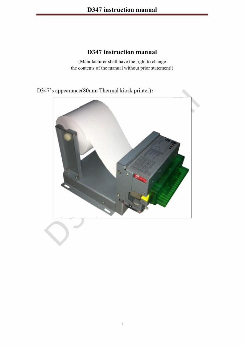
D347’s appearance(80mm Thermal kiosk printer)

D347 instruction manual!
II
CATALOG 1. Summary ....................................................................................................................................... 5
1.1Product Features ................................................................................................................... 5 1.1.1 General Specifications ............................................................................................. 5 1.1.2 Main Application and Ranges .................................................................................. 6 1.1.3 Product Features ....................................................................................................... 7 1.1.4 Supported character sets ........................................................................................... 8 1.1.5 Printer mechanism .................................................................................................... 8 1.1.6 Function and application .......................................................................................... 8 1.1.7 Hardware .................................................................................................................. 9
1.2 The main purpose ................................................................................................................ 9 1.3 Environmental Conditions .................................................................................................. 9 1.4 Electrical Characteristics ..................................................................................................... 9 1.5 Status light ......................................................................................................................... 10 1.6 Product Safety ................................................................................................................... 10 1.7 Matters need attention ....................................................................................................... 11
2. Installion ...................................................................................................................................... 12 2.1 D347 printing module operation instruction ..................................................................... 12 2.2 D347 Paper roll installation .............................................................................................. 12 2.3 D347 presentation ............................................................................................................. 14 2.4 D347 Power connection .................................................................................................... 17
3. Accessories .................................................................................................................................. 18 3.1 Power Supply Connector ................................................................................................... 18 3.2 USB connector cable ......................................................................................................... 18 3.3 RS-232 connector cable .................................................................................................... 19
3.3.1 RS-232 Serial Interface .......................................................................................... 19 3.4 DIP Switch ........................................................................................................................ 21
4. Functions ..................................................................................................................................... 22 4.1 List of Commands ............................................................................................................. 22
4.1.1Kanji command list ................................................................................................. 24 4.2 Commands ......................................................................................................................... 24
4.2.1 Command Notation ................................................................................................ 24 4.2.2 Explanation of Terms ............................................................................................. 25
4.3 Commands explanation ..................................................................................................... 27 4.3.1 Control Commands ................................................................................................ 27 ESC @ ............................................................................................................................. 27 GS ( A pL pH n m ........................................................................................................... 27 HT ................................................................................................................................... 27 LF .................................................................................................................................... 28 CR ................................................................................................................................... 28 ESC J n ............................................................................................................................ 28 ESC d n ........................................................................................................................... 29 ESC c 5 n ......................................................................................................................... 29

D347 instruction manual!
III
4.3.2 Character parameter setting command ................................................................... 29 ESC ! n ......................................................................................................................... 29 GS ! n ........................................................................................................................... 30 ESC M n .......................................................................................................................... 31 ESC – n ........................................................................................................................... 32 ESC E n ........................................................................................................................... 32 ESC G n ........................................................................................................................... 33 GS B n ............................................................................................................................. 33 ESC V n ........................................................................................................................... 34 FS &(Kanji Control Commands) .................................................................................... 34 FS . .................................................................................................................................. 35 FS ! n ............................................................................................................................... 35 FS - n ............................................................................................................................... 36 FS S n1 n2 ....................................................................................................................... 37 ESC R n ........................................................................................................................... 37 ESC { n ............................................................................................................................ 38 GS c ................................................................................................................................. 38 4.3.3 Parameter setting command ................................................................................... 39 ESC $ nL nH ................................................................................................................... 39 ESC \ nL n ....................................................................................................................... 39 ESC D n1…nk NULL ..................................................................................................... 39 ESC 2 .............................................................................................................................. 40 ESC 3 n ........................................................................................................................... 40 ESC SP n ......................................................................................................................... 41 ESC a n ............................................................................................................................ 41 GS L nL nH ..................................................................................................................... 41 GS .............................................................................................................................. 42 4.3.4 Graphics / image print command ........................................................................... 42 GS v 0 m xL xH yL yH d1…dk ...................................................................................... 42 FS P n m ................................................................................................................. 44 GS * x y d1…d x y 8 ................................................................................................ 45 4.3.5 Bar code print command ........................................................................................ 45 GS h n .............................................................................................................................. 45 GS w n ............................................................................................................................. 46 GS H n ............................................................................................................................. 46 GS f n .............................................................................................................................. 47 GS p n .............................................................................................................................. 47 GS k ................................................................................................................................. 47 4.3.6 Printer Status Feedback .......................................................................................... 51 DLE EOT n ..................................................................................................................... 51 DLE ENQ n ..................................................................................................................... 53 GS r n .............................................................................................................................. 54 4.3.7 Cutter Control ......................................................................................................... 55 GS V m/GS V m n ......................................................................................... 55
D347 instruction manual!
IV
ESC i ............................................................................................................................... 55 ESC m ............................................................................................................................. 55
5. Storage ......................................................................................................................................... 56 6. Appendix ..................................................................................................................................... 56
Appendix A Miscellaneous notes ....................................................................................... 56 A.1 Notes on Printing and Paper Feeding ....................................................................... 56 A.2 Notes on Connecting the External Power Supply .................................................... 57
Appendix B CODE128 BAR CODE ................................................................................. 57 B.1 Description of the CODE128 Bar Code ................................................................... 57 B.2 Code Tables .............................................................................................................. 58
Appendix C Switching Online and Offline ........................................................................ 61
D347 instruction manual!
5
1. Summary
This Manual is used for the D347 print module.If there are any question, please contact us!
1.1Product Features
1.1.1 General Specifications
items& Specifications
Printing method 80mm Thermal dot line printing Total dots per line dot/lines 576dots Printable dots per line dot/lines 576dots Simultaneously activated dots 96dots Print Density 85% Resolution W 8 dots/mm*H 16 dots/mm Paper feed pitch 0.03125mm Maximum print speed mm/smax
170
Print width mm 72 Paper width mm 80mm Paper cutting method Slide cutting Type of paper cutting Full cut and Partial cut
Detection Thermal head temperature detection
Thermistor
Platen position detection mechanical switch Out-of-paper detection Reflection type photo interrupter Cutter home position detection Transmissive type photo interrupter
Condition Operating voltage range(Vp) 24V±10% Current consumption Approximately 1.75A Autocutter current consumption 6.0 A max
Temperature Operating temperature -10—60 C Non condensing
Storage temperature -20—70 C Non condensing Operating humidity 10 85%RH Non condensing
Life span Activation pulse resistance 100 million pulses or more Abrasion resistance(km) 50km or more
Appearance Dimensions(include mounth part) W207.3mm*D121.5mm*H127.2mm Mass Approximately 550g

D347 instruction manual!
6
1.1.2 Main Application and Ranges
1 Dimension diagram

D347 instruction manual!
7
1.1.3 Product Features
D347 use Seiko printer machine CAPD347, combined with the company

D347 instruction manual!
8
independent research and development D347 PCB and metal structure.Small panel structure, using the latest ARM design and printers movement in the same institution, reduce the space of the installation, the installation of improve product reliability; The design is exquisite, stable performance and fashion appearance. With automatic feed, automatic paper cutting, paper detection, paper near end sensor, paper prevent jam, paper pull, paper presenter and so on.
Interface: Serial port (RS-232 or TTL), USB, parallel. Driver Support: XP /Win7/ WIN8 32bit and 64bit . Barcode fuction: Support a dimensional barcode, such as CODE 93, CODE128
etc, support the two-dimensional barcode PDF417, QRCODE. Paper pull and paper prevent jam: Paper near end sensor: Onlight: noamal state, paper is enough. Offlight: paper near end sensor.
1.1.4 Supported character sets
! FONT A 12*24 dot characters ! FONT B 9*17 dot characters ! Kanji Support GB18030 Simplified Chinese 24*24 dots
Support GB2312 Simplified Chinese 16*16dots (Please contact us)
1.1.5 Printer mechanism
Now it adopts Seiko printer mechanism.
1.1.6 Function and application
! Apply to ESC/POS standard command (customization command provided by company).
! Character size can be enlarged to 64 times. ! It can make reiteration and copy printing. It can print bar code (palisade
barcode, standard EAN13 barcode).

D347 instruction manual!
9
! It can choose the character size by command (12*24/9*17). ! It can choose the character size by command (24*24/16*16). ! It can print bitmap. ! It can choose printing pattern and page by software setup.
1.1.7 Hardware
! It equipped with Serial port (RS-232 or TTL) /USB. ! It equips with power adapter, paper near end sensor, control switch, paper
presenter, communication cable, etc. ! It can add paper prevent jam paper pull and paper detection function.
1.2 The main purpose
D347 module is our new design printing module; it has high speed, low noise and good reliability. Moreover, it owns compact structure, which is convenient for installation.
The control board supports various barcode printing, including: EAN8, EAN13, CODE39, CODE128 one-dimension barcodes and the PDF417 qr code printing, etc.
The best outstanding feature is our ALL-IN-ONE design concept control board and printer mechanism are in one structure, it commendably takes user’ design into consideration, this can provide more convenience for users.It can apply to different industrial areas. For example: ATM The parking lot,self-service equipment, etc.
1.3 Environmental Conditions
" Temperature Operating -10-60 C Storage -20-70 C " Humidity Operating 10-85% RH(non-condensation)(85%RH must be at 40 C)
1.4 Electrical Characteristics
" Supply voltage 24V " Current consumption(at 24V)
! High speed mode Peak Approximately 6.0A Mean Approximately 1.75A

D347 instruction manual!
10
1.5 Status light
There are three LED lights on the machine use to indicate each state meaning is as follows
Green LED: onlight, power supply; Red(two) LEDs: quick-flashing, power voltage is wrong. ERROR_LED is offlight, and the PE_LED flash slowly, it means the lack of paper,
can be normal after the paper loading. After paper loading , red LED is offlight; if paper near end sensor is valid, when the
paper is not enough, PE is bright but the printer can continue to print.
1.6 Product Safety
# Do not apply voltage or current to any pins in excess of the absolute maximum ratings.If voltage or current in excess of the absolute maximum ratings is applied, excess current will flow through the device, which may result in heat damage.
Absolute Maximum Ratings Item Symbol Rated value Unit Input voltage VIN 26.4 V Storage temperature Tstg -20 to 70 C
Recommended Operating Conditions
Item Symbol Standard value Unit Min. Typ. Max.
Supply voltage to the printer Vp 21.6 24 26.7 V Operating temperature Topr 10 -- 60 C Storage humidity Hopr 10 -- 85 %
# Do not short-circuit any of the output pins with the power
supply.Short-circuiting an output pin with a low-impedance power supply may cause heat damage due to excess current or may melt the bonding wire.
# During transport or storage, protect the device by storing it in conductive sponge, aluminum foil, etc.
# Do not drop conductive material such as a paper clip onto the circuit board.Short circuiting pins on the board may cause heat damage due to excess current or may melt the bonding wire.
# Be sure to connect the devices with the specified cables.Improper connection may cause fire or shock.
# Never disassemble or modify this product.Tampering with this product may result in injury, fire, or electric shock.
# Be sure to set this equipment on a firm, stable, horizontal surface.Product

D347 instruction manual!
11
may break or cause injury if it falls. # Do not use in locations subject to high humidity or dust levels.Excessive
humidity and dust may cause equipment damage, fire, or shock. # Do not place heavy objects on top of this product. Never stand or lean on this
product.Equipment may fall or collapse, causing breakage and possible injury. # To ensure safety, please unplug this product prior to leaving it unused for an
extended period.
1.7 Matters need attention
1. Recommend that client use the power adapter provides by our company.
If want to use your own power adapter, shall meet the following
requirements: output voltage: 24V, rated current: 2A~3A.
2. User should not touch printing control board without any static
protection, because static can damage any electrical components on
board and leads to no work of board.
3. User should use standard thermal paper, or it can influence our printer,
moreover, it can damage thermal head gradually.
4. The width, inner diameter, outer diameter of paper scroll have meet
standard requirements, or it can make paper sensor unable to work and
paper jam.
5. User can’t pull out the cable or power wire when the board is power on.
6. After long time working printer head will emit heat normally, but user
can not touch it directly, or will get scald.
7. There is amounts of frictional force between the rubber roll and thermal
head, so user can not press paper feeding button when where is no paper
or it can damage thermal head.
8. User should clean thermal head regularly (use C2H5OH).
9. User should clean paper sensor regularly. NOTE: User can not turn on and turn off power continuously,after 10 seconds can restart the printer.

D347 instruction manual!
12
2. Installion
2.1 D347 printing module operation instruction
For example
2.2 D347 Paper roll installation
1) Use scissors to snip paper in order to make it flat, as follows
Communication interface
DIP Switch
Power interface
Paper mouth
Fixed hole

D347 instruction manual!
13
2) put the paper roll honzontally or upright into the paper entry when printer is on power, make sure the thermal layer up, as follow
3) When the printer detects the paper, then the printer will feed paper automatically.
4) Press the Self-test button, then printer prints out a self- test page. As follow:
Thermal layer

D347 instruction manual!
14
5) According to the self-test page, set the DIP switch position, accomplish the
corresponding function requirements.
2.3 D347 presentation
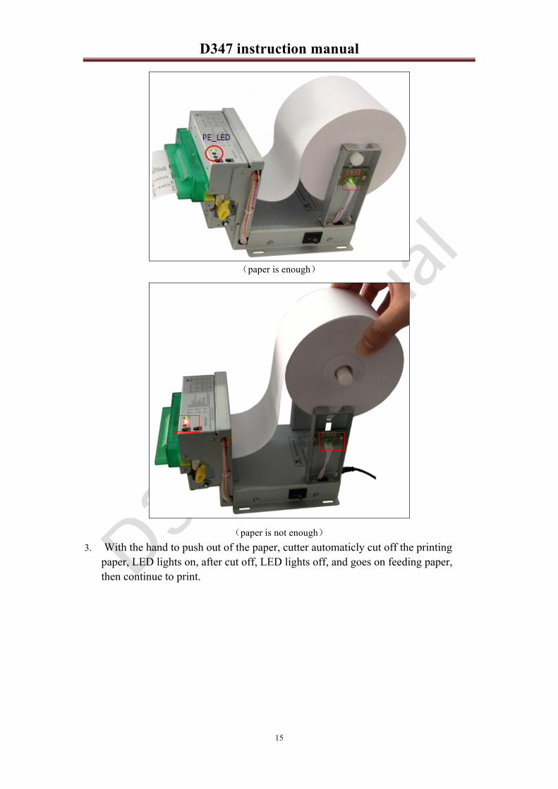
1. After power on, go for a paper and automaticly cut.When install paper-presenter structure, the feeding length is not enough, cutter will not cut. After printing, if the paper has not been taken out, the paper will recycling in a few seconds.
2. Set the DIP switch is invalid or valid. When the paper near end sensor is valid, in the situation of paper enough, the status indicator PE_LED lights off; Paper is not enough, the status indicator PE_LED lights on, the indicator on the paper near end sensor module will light off.
D347 instruction manual!
15
paper is enough
paper is not enough 3. With the hand to push out of the paper, cutter automaticly cut off the printing
paper, LED lights on, after cut off, LED lights off, and goes on feeding paper, then continue to print.

D347 instruction manual!
16
4. With the hand to block out of the paper, paper printers automatically stop, LED
lights on, the paper feed smoothly, LED lights off, and then continue to print.
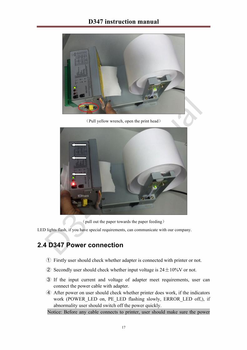
5. If paper jam occurs, tear the paper outside the paper entry, and pull yellow wrench,
open the print head and pull out the jammed paper towards the paper feeding. And then return cover, back to power on, according to the installation of the paper for printer paper again.
6. Press “Feed” button; observe whether the fault is excluded.
Tear the paper outside the paper entry
D347 instruction manual!
17
Pull yellow wrench, open the print head
pull out the paper towards the paper feeding
LED lights flash, if you have special requirements, can communicate with our company.
2.4 D347 Power connection
� Firstly user should check whether adapter is connected with printer or not.
� Secondly user should check whether input voltage is 24 10%V or not.
� If the input current and voltage of adapter meet requirements, user can connect the power cable with adapter.
� After power on user should check whether printer does work, if the indicators work (POWER_LED on, PE_LED flashing slowly, ERROR_LED off,), if abnormality user should switch off the power quickly.
Notice: Before any cable connects to printer, user should make sure the power

D347 instruction manual!
18
off.
3. Accessories
The interface of D347:
3.1 Power Supply Connector
<Power supply connection cable> – female interface, 2.5mm, as follow
3.2 USB connector cable
<Type B connector cable>, as follow

D347 instruction manual!
19
3.3 RS-232 connector cable
RS-232 connector cable- female interface, as follow
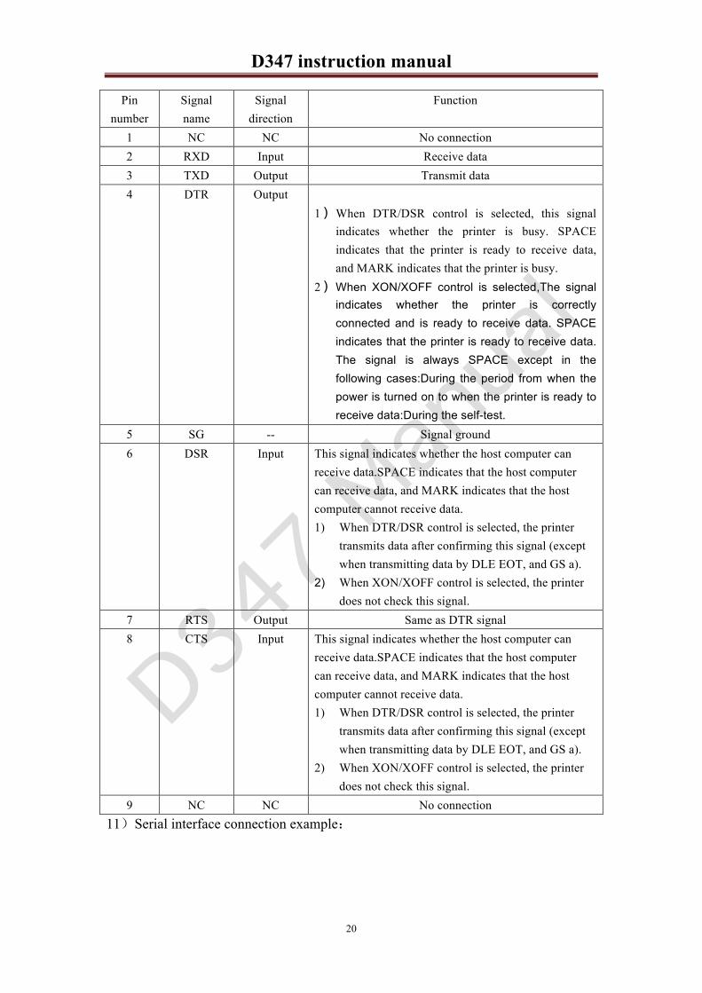
3.3.1 RS-232 Serial Interface
1 Data transmission Serial 2 Synchronization Asynchronous 3 Baud rate 115200 9600 19200 38400bps(bit per second) 4 Data word length 8 bits (fixed) 5 Parity Setting None,even,odd 6 Stop bits 1 or more 7 Connector(printer side) male D-SUB9 pin connector 8 Signal levels MARK = -3 to -15 V: Logic "1"/ OFF
SPACE = +3 to +15 V: Logic "0"/ ON 9 Handshaking Software Xon/Xoff
Hardware RTS/CTS DTR/DSR 10 Signal Assignments and Functions
D347 instruction manual!
20
Pin number
Signal name
Signal direction
Function
1 NC NC No connection 2 RXD Input Receive data 3 TXD Output Transmit data 4 DTR Output
1� When DTR/DSR control is selected, this signal indicates whether the printer is busy. SPACE indicates that the printer is ready to receive data, and MARK indicates that the printer is busy.
2� When XON/XOFF control is selected,The signal indicates whether the printer is correctly connected and is ready to receive data. SPACE indicates that the printer is ready to receive data. The signal is always SPACE except in the following cases:During the period from when the power is turned on to when the printer is ready to receive data:During the self-test.
5 SG -- Signal ground 6 DSR Input This signal indicates whether the host computer can
receive data.SPACE indicates that the host computer can receive data, and MARK indicates that the host computer cannot receive data. 1) When DTR/DSR control is selected, the printer
transmits data after confirming this signal (except when transmitting data by DLE EOT, and GS a).
2) When XON/XOFF control is selected, the printer does not check this signal.
7 RTS Output Same as DTR signal 8 CTS Input This signal indicates whether the host computer can
receive data.SPACE indicates that the host computer can receive data, and MARK indicates that the host computer cannot receive data. 1) When DTR/DSR control is selected, the printer
transmits data after confirming this signal (except when transmitting data by DLE EOT, and GS a).
2) When XON/XOFF control is selected, the printer does not check this signal.
9 NC NC No connection 11 Serial interface connection example

D347 instruction manual!
21
3.4 DIP Switch
SW No. Function ON OFF Factory setting
1 BM sensor Enabled Disable Off 2 Interface selection Refer to table 3.4.1 Off 3 Off 4 Paper near-end sensor Enabled Disable Off 5 Print density selection Refer to table 3.4.2 Off(*) 6 Off(*) 7 Baud rate Adjustment Refer to table 3.4.3 Off(*) 8 Off(*)
(*)Effective only when the serial interface is selected. Table 3.4.1 Interface choose Interface Switch number
2 3 Parallel interface OFF OFF Serial interface OFF ON
ON OFF USB ON ON
Table 3.4.2 Print Density Selection Level Print density Switch number
5 6 1 145% ON ON 2 130% OFF ON 3 115% ON OFF 4 100% OFF OFF
Table 3.4.3 Baud Rate Selection Transmission Speed BPS Switch number

D347 instruction manual!
22
7 8 115200 ON ON
9600 OFF ON 19200 ON OFF 38400 OFF OFF
BPS: bit per second Notice DIP switches should not be changed while the printer power is on. Effective only when reset the printer.
4. Functions
4.1 List of Commands
Command Name Command classification
Standard mode
Executing Setting HT Horizontal tab o o LF Print and line feed o o CR Print and carriage return o o DLE EOT Real-time status transmission o o DLE ENQ Real-time request to printer o o ESC SP Set right-side character spacing o o ESC Select print mode(s) o o ESC $ Set absolute print position o o ESC * Select bit-image mode o o ESC - Turn underline mode on/off o o ESC 2 Select default line spacing o o ESC 3 Set line spacing o o ESC @ Initialize printer o o o ESC D Set horizontal tab positions o o ESC E Turn emphasized mode on/off o o ESC G Turn double-strike mode on/off o o ESC J Print and feed paper o o ESC M Select character font o ESC R Select an international character set o o ESC V Turn 90° clockwise rotation mode
on/off o o
ESC \ Set relative print position o o ESC a Select justification o (o) ESC c 3 Select paper sensor(s) to output
paper-end signals o o

D347 instruction manual!
23
ESC c 4 Select paper sensor(s) to stop printing
o o
ESC c 5 Enable/disable panel buttons o o ESC d Print and feed n lines o o ESC t Select character code table o o ESC{ Turn upside-down printing mode
on/off o (o)
FS p Print NV bit image o o FS q Define NV bit image o (o) GS ! Select character size o o GS* Define downloaded bit image o o GS ( A Execute test print o o GS (E User setup commands o o (o) GS (F Set adjustment values(s) o o GS (K Select print control method(s) o o GS ( M Customize printer control value(s) o (o) GS / Print downloaded bit image o GS Start/end macro definition o o o GS B Turn white/black reverse printing
mode on/off o o
GS C 0 Select counter print mode o o GS C 1 Select count mode (A) o o GS C 2 Set counter o o GS C Select count mode (B) o o GS E Select head control method o o GS H Select printing position of HRI
characters o o
GS I Transmit printer ID o o GS L Set left margin o (o) GS T Set print position to the beginning
of print line o o
GS V Select cut mode and cut paper o (o) GS W Set printing area width o (o) GS ^ Execute macro o o GS a Enable/disable Automatic Status
Back (ASB) o o o
GS b Turn smoothing mode on/off o o GS f Select font for HRI characters o o GS h Set bar code height o o GS k Print bar code o GS r Transmit status o o GS v 0 Print raster bit image o GS w Set bar code width o o

D347 instruction manual!
24
4.1.1Kanji command list
Command Name Command classification
Standard mode
Executing Setting FS ! Set print mode(s) for Kanji
characters o o
FS & Select Kanji character mode o o FS - Turn underline mode on/off for
Kanji characters o o
FS . Cancel Kanji character mode o o FS C Select Kanji character code
system o o
FS S Set left- and right-side Kanji character spacing
o o
FS W n Turn quadruple-size mode on/off for Kanji characters
o o
[instructions] Command classification Executing The printer executes the command, which does not then affect the
following data. Setting The printer uses flags to make settings,and those settings affect the
following data. Standard mode o: Enabled. (o):Enable only when the command is set at the beginning of a line. :Enable only when data is not present in the printer buffer.
4.2 Commands
4.2.1 Command Notation
[Name] The name of the command; [Format] The code sequence;
[ ]k indicates the contents of [ ] should be repeated k times. [Range] Gives the allowable ranges for the arguments; [Description] Describes the function of the command; [Details] Describes the usage of the command in detail; [Notes] Provides important information on setting and using the
printer command, if necessary; [Default] Gives the default values, if any, for the command parameters; [Reference] Lists related commands.

D347 instruction manual!
25
The numbers denoted by < >H are hexadecimal. The numbers denoted by < >B are binary. The parameters in the range of data in the command format, based on the scope
of the < > D, namely the Decimal number range.For example,0 n 255 <n>D
4.2.2 Explanation of Terms
1) Receive buffer The receive buffer is a buffer that stores, as is, the data received from the host
(the reception data). The receive data is stored in the receive buffer temporarily, and is then processed sequentially.
2) Print buffer The print buffer is a buffer that stores the image data to be printed. 3) Print buffer full This is the state where there is no more room in the print buffer. If new print data
is input while the print buffer is full, the data in the print buffer is printed out and a line feed is executed. This is the same operation as the LF(Print and line feed) operation.
4) Start of line The start of line state satisfies the following conditions: There is no print data (including spaces and portions of data skipped due to
HT(Horizontal tab) currently in the print buffer. The print position is not specified by the ESC $(Set absolute print position) or
ESC \ (Set relative print position)command. 5) Printable area The maximum range within printing is possible under the printer specifications.
The printable area for this printer is as follows: For 80mm paper width model approximately 72mm.
Dot pitch
6) Printing area Printing range is set by the command.The printing area area must be the
printable area.

D347 instruction manual!
26
7) Ignore The state in which all codes including parameters are read in and discarded
and nothing happens. 8) Inch A unit of lenth.One inch is 25.4mm. 9) MSB Most Significant Bit 10) LSB Least Significant Bit 11) Baseline The standard position for character data stored in the print buffer.The illustration
below shows normal character positions in standard mode
*1. When Font A (12 24 dots) is selected, this height is 21 dots.
When Font B (9 17 dots) is selected, this height is 16 dots. Rotated characters in standard mode (only when Font A is selected):

D347 instruction manual!
27
4.3 Commands explanation
4.3.1 Control Commands
ESC @
[Name] Initialize printer [Format] ASCII ESC @
Hex 1B 40 Decimal 27 64 [Description] Clears the data in the print buffer and resets the printer mode to the
mode that was in effect when the power was turned on. [Notes] The data in the receive buffer is not cleared.
GS ( A pL pH n m
[Name] Execute test print [Format] ASCII GS ( A pL pH n m
Hex 1D 28 41 02 00 00 02 Decimal 29 40 65 3 0 0 2 [Description] Executes a test print with a specified test pattern on a specified paper. [Details] •This command has enabled only when processed at the beginning of a
line in standard mode. •When this command is received during macro definition, the printer ends macro definition and begins performing this command. •After the test print is finished, the printer resets itself automatically. Therefore,data already defined before this command is executed, such as user-defined characters, downloaded bit image, and macro, becomes undefined; the receive buffer and print buffer are cleared; and each setting returns to the default value. •The printer also re-reads the DIP switch settings. •The printer cuts the paper at the end of the test print. •The printer goes BUSY while this command is executed.
HT
[Name] Horizontal tab [Format] ASCII HT Hex 09 Decimal 9 [Description] Moves the print position to the next horizontal tab position. [Notes] •This command is ignored unless the next horizontal tab position has

D347 instruction manual!
28
been set. •If the next horizontal tab position exceeds the printing area, the printer
sets the printing position to [printing area width + 1]. •Horizontal tab positions are set with ESC D(Set horizontal tab
positions). •If this command is received when the printing position is at [printing
area width +1], the printer executes print buffer-full printing of the current line and horizontal tab processing from the beginning of the next line.
[Reference] ESC D(Set horizontal tab positions)
LF
[Name] Print and line feed [Format] ASCII LF Hex 0A Decimal 10 [Description] Prints the data in the print buffer and feeds one line, based on the
current line spacing. [Note] This command sets the print position to the beginning of the line. [Reference] ESC 2(default line spacing) ESC 3(set line spacing)
CR
[Name] Print and carriage return [Format] ASCII CR Hex 0D Decimal 13 [Description] When automatic line feed is enabled, this command functions the same
as LF; when automatic line feed is disabled, this command is ignored.
[Reference] LF(Print and line feed)
ESC J n
[Name] Print and feed paper. [format] ASCII ESC J n
Hex 1B 4A n Decimal 27 74 n [Range] 0 n 255 [Description] Prints the data in the print buffer and feeds the paper [n 0.125 mm]. [Notes] •After printing is completed, this command sets the print starting
position to the beginning of the line.

D347 instruction manual!
29
•The paper feed amount set by this command does not affect the values set by ESC 2(default line spacing) ESC 3(set line spacing).
ESC d n
[Name] Print and feed n lines [Format] ASCII ESC d n
Hex 1B 64 n Decimal 27 100 n [Range] 0 n 255 [Description] Prints the data in the print buffer and feeds n lines. [notes] •This command sets the print starting position to the beginning of the
line. •This command does not affect the line spacing set by ESC 2 or ESC 3. •The maximum paper feed amount is 1016 mm {40"}. If the paper feed a mount (n line spacing) of more than 1016 mm {40"} is specified, the printer feeds the paper only 1016 mm {40"}.
[Reference] ESC 2(default line spacing) ESC 3(set line spacing)
ESC c 5 n
[Name] Enable/disable panel buttons [Format] ASCII ESC c 5 n
Hex 1B 63 35 n Decimal 27 99 53 n [Range] 0 n 255 [Description] Enables or disables the panel buttons.
When the LSB of n is 0, the panel buttons are enabled. When the LSB of n is 1, the panel buttons are disabled.
[Notes] • Only the lowest bit of n is valid. • When the panel buttons are disabled, none of them are usable when the printer cover is closed.
• In this printer, the only panel buttons is the FEED button. • When in macro execution standby, the FEED button is enabled
regardless of the setting of this command. However, the paper cannot be fed.
[Default] n=0
4.3.2 Character parameter setting command
ESC ! n
[Name] Select print mode(s)

D347 instruction manual!
30
[Format] ASCII ESC ! n Hex 1B 21 n
Decimal 27 33 n [Range] 0 n 255 [Description] Selects print mode(s) using n as follows:
bit Off/On Hex Decimal Function 0 Off 00 0 Character Font A (12 24).
On 01 1 Character Font B (9 17). 1 - - - Undefined. 2 - - - Undefined. 3 Off 00 0 Emphasized mode not selected.
On 08 8 Emphasized mode selected. 4 Off 00 0 Double-height mode not selected.
On 10 16 Double-height mode selected. 5 Off 00 0 Double-width mode not selected.
On 20 32 Double-width mode selected. 6 - - - Undefined. 7 Off 00 0 Underline mode not selected.
On 80 128 Underline mode selected. [Detials] •When both double-height and double-width modes are selected,
quadruple-size characters are printed. •The printer can underline all characters, but cannot underline the space
set by HT or 90 clockwise rotated characters. •The thickness of the underline is that selected by ESC −, regardless of
the character size. •When some characters in a line are double or more height, all the
characters in the line are aligned at the baseline. •ESC M(Select character font)can also select character font type.
However, the setting of the last received command is effective. •ESC E(Turn emphasized mode on/off)can also turn on or off
emphasized mode. However, the setting of the last received command is effective.
•ESC (Turn underline mode on/off)can also turn on or off underline mode. However, the setting of the last received command is effective.
•GS !(Select character size)can also select character size. However, the setting of the last received command is effective.
•Emphasized mode is effective for alphanumeric and Kanji. All print modes except emphasized mode are effective only for alphanumeric.
GS ! n
[Name] Select character size
D347 instruction manual!
31
[Format] ASCII GS ! n Hex 1D 21 n
Decimal 29 33 n [Range] 0 n 255
(1 ≤ vertical number of times ≤ 8, 1 ≤ horizontal number of times ≤ 8) [Description] Selects the character height using bits 0 to 2 and selects the character
width using bits 4 to 7, as follows: Table 1 Table 2
Character Width Selection Character Height Selection Hex Decimal Width 00 0 1(normal) 10 16 2(double-width) 20 32 3 30 48 4 40 64 5 50 80 6 60 96 7 70 112 8
[Notes] •This command is effective for all characters (alphanumeric and Kanji),
except for HRI characters. •If n is outside the defined range, this command is ignored. •In standard mode, the vertical direction is the paper feed direction, and the horizontal direction is perpendicular to the paper feed direction. However, when character orientation changes in 90 clockwise-rotation mode, the relationship between vertical and horizontal directions is reversed. In page mode, vertical and horizontal directions are based on the character orientation. When characters are enlarged with different sizes on one line, all the characters on the line are aligned at the baseline. The ESC ! (Select print modes) command can also turn double-width and double-height modes on or off. However, the setting of the last received command is effective.
[Default] n=0 [Reference] ESC !(Select print modes)
ESC M n
[Name] Select character font [Format] ASCII ESC M n
Hex 1B 4D n Decimal 27 77 n [Range] n=0,1,16,17 [Description] Select the character font.
Hex Decimal Height 00 0 1(normal) 01 1 2(double-height) 02 2 3 03 3 4 04 4 5 05 5 6 06 6 7 07 7 8

D347 instruction manual!
32
F A 9DR .LF KAGF
9I9 K I .GFK * J D K 9I9 K I .GFK ) ( J D K
29FBA 9I9 K I .GFK * RJ D K
( 29FBA 9I9 K I .GFK J D K
[Details] ESC ! (Select print modes) can also select character font types. However the setting of the lastreceived command is effective.
[Reference] ESC ! (Select print modes)
ESC – n
[Name] Turn underline mode on/off [Format] ASCII ESC – n
Hex 1B 2D n Decimal 27 45 n [Range] 0 n 2 [Description] Turns underline mode on or off, based on the following values of n:
F .LF KAGF
7LIFJ G LF IDAF G
Turns on underline mode(1dot thick)Turns on underline mode(2 dots thick)
[Notes] • The printer can underline all characters (including right-side character
spacing),but cannot underline the space set by HT(Horizontal tab). • The printer cannot underline 90 clockwise rotated characters and white/black inverted characters. When underline mode is turned off by setting the value of n to 0 or 48, the following data is not underlined, and the underline thickness set before the mode is turned off does not change. Changing the character size does not affect the current underline thickness. Underline mode can also be turned on or off by using ESC !( Select print modes). Note, however, that the last received command is effective.
[Default] n=0 [Reference] ESC !( Select print modes)
ESC E n
[Name] Turn emphasized mode on/off [Format] ASCII ESC E n
Hex 1B 45 n Decimal 27 69 n

D347 instruction manual!
33
[Range] 0 n 255 [Description] Turns emphasized mode on or off
When the LSB of n is 0, emphasized mode is turned off. When the LSB of n is 1, emphasized mode is turned on.
[Notes] • Only the least significant bit of n is enabled. • This command and ESC !( Select print modes) turn on and off emphasized mode in the same way.Be careful when this command is used with ESC !.
[Default] n=0 [Reference] ESC !( Select print modes)
ESC G n
[Name] Turn on/off double –strike mode [Format] ASCII ESC G n
Hex 1B 47 n Decimal 27 71 n [Range] 0 n 255 [Description] Turn double-strike mode on or off.
• When the LSB of n is 0, double-strike mode is turned off. • When the LSB of n is 1, double-strike mode is turned on.
[Notes] • Only the lowest bit of n is enabled. • Printer output is the same in double-strike mode and in emphasized mode.
[Default] n=0 [Refercnce] ESC E(Turn emphasized mode on/off)
GS B n
[Name] Turn white/black reverse printing mode [Format] ASCII GS B n
Hex 1D 42 n Decimal 29 66 n [Range] 0 n 255 [Description] Turn on or off white/black reverse printing mode.
• When the LSB of n is 0, white/black reverse mode is turned off. • When the LSB of n is 1, white/black reverse mode is turned on.
[Notes] • Only the lowest bit of n is valid. • This command is available for built-in characters and user-defined characters.
• When white/black reverse printing mode is on, it also applies to character spacing set by ESC SP(Set right-side character spacing).
• This command does not affect bit images, user-defined bit images, bar codes,HRI characters, and spacing skipped by HT(Horizontal tab),
D347 instruction manual!
34
ESC $(Set absolute print position), and ESC \(Set relative print position).
• This command does not affect the space between lines. • White/black reverse mode has a higher priority than underline mode. Even if underline mode is on, it is disabled (but not canceled) when white/black reverse mode is selected.
[Default] n=0
ESC V n
[Name] Turn 90 clockwise rotation mode on/off [Format] ASCII ESC V n
Hex 1B 56 n Decimal 27 86 n [Range] 0 n 1, 48 n 49 [Description] Turns 90 clockwise rotation mode on/off
n is used as follows:
n Function 0,48 Turns off 90 clockwise rotation mode 1,49 Turns on 90 clockwise rotation mode
[Notes] • This command affects printing in standard mode. However, the setting is always effective. • When underline mode is turned on, the printer does not underline 90clockwise-rotated characters. Double-width and double-height commands in 90 rotation mode
enlarge characters in the opposite directions from double-height and double- width commands in normal mode. If this command is input in page mode, the printer performs only
internal flag operations. [Default] n=0 [Reference] ESC !(Select print modes) ESC –(Turn underline mode onoff)
FS &(Kanji Control Commands)
[Name] Select Kanji character mode [Format] ASCII FS &
Hex 1C 26 Decimal 28 38 [Description] Select Kanji character mode. [Details] For Japanese model:
• This command is effective only when the JIS code system is selected. • When the Kanji character mode is selected, the printer processes all Kanji code as two bytes each.

D347 instruction manual!
35
• Kanji codes are processed in the order of the first byte and second byte.
• Kanji character mode is not selected when the power is turned on. • Using FS C, the Kanji character code system is selected. For Simplified Chinese/Traditional Chinese / Korean model: • When The kanji character mode is selected, the printer checks whether the code is for Kanji or not; then processes the first byte and the second byte if the code is for Kanji. • Kanji codes are processed in the order of the first byte and second byte. • Kanji character mode is selected when the power is turned on.
[Reference] FS.(Cancel Kanji character mode) FS C(Select Kanji character code system)
FS .
[Name] Cancel Kanji character mode [Format] ASCII FS .
Hex 1C 2E Decimal 28 46 [Description] Cancel Kanji character mode. [Details] For Japanese model:
• This command is effective only when the JIS code system is selected. • When the Kanji character mode is not selected, all character codes are processed one byte at a time as ASCII code.
• Kanji character mode is not selected when the power is turned on. For Simplified Chinese/Traditional Chinese / Korean model: • When the Kanji character mode is not selected, all character codes are processed one byte at a time as ASCII code. • Kanji character mode is selected when the power is turned on.
[Reference] FS &(Select Kanji character mode) FS C(Select Kanji character code system)
FS ! n
[Name] Set print mode(s) for Kanji characters [Format] ASCII FS ! n
Hex 1C 21 n Decimal 28 33 n [Range] 0 n 255 [Description] Sets the print mode for Kanji characters, using n as follows:
bit Off/On Hex Decimal Function 0 - - - Undefined 1 - - - Undefined

D347 instruction manual!
36
2 Off 00 0 Double-width mode is OFF. On 04 4 Double-width mode is ON.
3 Off 00 0 Double-height mode is OFF. On 08 8 Double-height mode is ON.
4 - - - Undefined. 5 - - - Undefined. 6 - - - Undefined. 7 Off 00 0 Underline mode is OFF.
On 80 128 Underline mode is ON. [Details] • When both double-width and double-height modes are set (including
right- and left-side character spacing), quadruple-size characters are printed.
• The printer can underline all characters (including right- and left-side character spacing), but cannot underline the space set by HT and 90° clockwise-rotated characters.
• The thickness of the underline is that specified by FS −, regardless of the character size.
• When some of the characters in a line are double or more height, all the characters on the line are aligned at the baseline.
• It is possible to emphasize the Kanji character using FS W or GS !; the setting of vthe last received command is effective.
• It is possible to turn underline mode on or off using FS −, and the setting of the last received command is effective.
[Default] n=0 [Reference] FS –(Turn underline mode on/off for Kanji character) GS !(Select
character size)
FS - n
[Name] Turn underline mode on/off for Kanji characters [Format] ASCII FS - n
Hex 1C 2D n Decimal 28 45 n [Range] 0 n 2 [Description] Turns underline mode for Kanji characters on or off, based on the
following values of n for both receipt and slip. n Function 0 Turns off underline mode for Kanji characteras 1 Turns on underline mode for Kanji characters
(1-dot thick) 2 Turns on underline mode for Kanji characters
(2-dot thick) [Details] • The printer can underline all characters (including right- and left-side
D347 instruction manual!
37
character spacing), but cannot underline the space set by HT and 90° clockwise-rotated characters.
• After the underline mode for Kanji characters is turned off by setting n to 0, underline printing is no longer executed, but the previously specified underline thickness is not changed. The default underline thickness is 1 dot.
• It is possible to turn underline mode on or off using FS !, and the last received command is effective.
• When the slip paper is selected, the underline thickness is 1 dot even if n is 2 .
[Default] n=0 [Reference] FS !( Set print mode(s) for Kanji characters)
FS S n1 n2
[Name] Set left- and right-side Kanji character spacing [Format] ASCII FS S n1 n2
Hex 1C 53 n1 n2 Decimal 28 83 n1 n2 [Range] 0 n1 255 0 n2 255 [Description] Sets left- and right-side Kanji character spacing to n1 and n2,
respectively.The left-side character spacing is [n1 0.125 mm], and the right-side character spacing is [n2 0.125 mm].
[Details] • This command sets the left- and right-side character spacing for normal-sized characters. When double-width mode is set, the left- and right-side character spacing is twice the normal value. • The spacing which is set with this command can be set independently in standard mode and in page mode. • In standard mode, the horizontal motion unit is used.
[Default] n1=0 n2=0
ESC R n
[Name] Select an international character set [Format] ASCII ESC R n
Hex 1B 52 n Decimal 27 82 n [Range] 0 n 13 [Description] Selects international character set n from the following table:
n 9I9 K I J K
0 6 *
1 .I9F
2 I 9F
D347 instruction manual!
38
3 2
4 F 9IC I5 6N F
6 0K9D
7 Spain I8 19 9F
9 4GIN9
10 F 9IC II11 6 9AF II12 9KAF * IA 9
13 Korea [Default] n=0
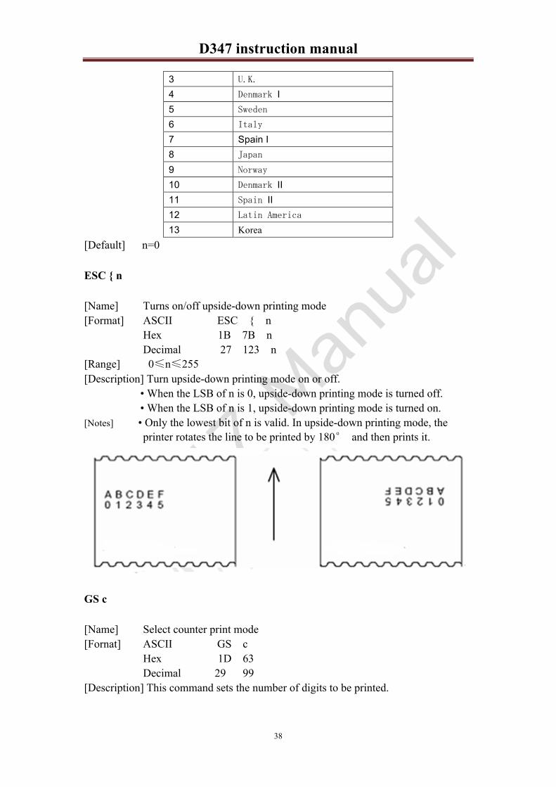
ESC { n
[Name] Turns on/off upside-down printing mode [Format] ASCII ESC { n
Hex 1B 7B n Decimal 27 123 n [Range] 0 n 255 [Description] Turn upside-down printing mode on or off.
• When the LSB of n is 0, upside-down printing mode is turned off. • When the LSB of n is 1, upside-down printing mode is turned on.
[Notes] • Only the lowest bit of n is valid. In upside-down printing mode, the printer rotates the line to be printed by 180 and then prints it.
GS c
[Name] Select counter print mode [Fornat] ASCII GS c
Hex 1D 63 Decimal 29 99 [Description] This command sets the number of digits to be printed.
D347 instruction manual!
39
4.3.3 Parameter setting command
ESC $ nL nH
[Name] Set absolute print position [Format] ASCII ESC $ nL nH
Hex 1B 24 nL nH Decimal 27 36 nL nH [Range] 0 nL 255 0 nH 255 [Description] Sets the distance from the beginning of the line to the position at which
subsequent characters are to be printed. • The distance from the beginning of the line to the print position is [(nL + nH 256) 0.125 mm].
[Details] • Settings outside the specified printable area are ignored. • In standard mode, the horizontal motion unit (x) is used.
[Reference] ESC \ (Set relative print position)
ESC \ nL nH
[Name] Set relative print position [Format] ASCII ESC \ nL nH
Hex 1B 5C nL nH Decimal 27 92 nL nH [Range] 0 nL 255 0 nH 255 [Description] Sets the print starting position based on the current position using
horizontal or vertical motion units. • This command sets the distance from the current position to [(nL + nH
256) 0.125 mm] [Notes] • Any setting that exceeds the printable area is ignored.
• When pitch N is specified to the right:nL+ nH 256 = N When pitch N is specified to the left (the negative direction), use the complement of 65536. When pitch N is specified to the left:nL+ nH 256 = 65536 - N
• In standard mode, the horizontal motion unit is used. [Reference] ESC $ Set absolute print position
ESC D n1 nk NULL
[Name] Set horizontal tab positions [Format] ASCII ESC D n1 nk NULL
Hex 1B 44 n1 nk 00 Decimal 27 68 n1 nk 0

D347 instruction manual!
40
[Range] 0 nL 255 0 k 8 [Description] Set horizontal tab positions.
• n specifies the column number for setting a horizontal tab position from the beginning of the line. • k indicates the total number of horizontal tab positions to be set.
[Notes] • The horizontal tab position is stored as a value of [character width n] measured from the beginning of the line. The character width includes the right-side character spacing, and double-width characters are set with twice the width of normal characters. • This command cancels the previous horizontal tab settings. • When setting n = 8, the print position is moved to column 9 by
sending HT. • Up to 32 tab positions (k = 32) can be set. Data exceeding 32 tab positions is processed as normal data. • Transmit [n]k in ascending order and place a NUL code 0 at the end. When [n]k is less than or equal to the preceding value [n]k-1, tab setting is finished and the following data is processed as normal data.
• ESC D NUL cancels all horizontal tab positions. • The previously specified horizontal tab positions do not change, even if the character width changes.
[Default] The default tab positions are at intervals of 8 characters (columns 9, 17, 25 ) for Font A (12 24).
[Reference] HT Horizontal tab
ESC 2
[Name] Select default line spacing [Format] ASCII ESC 2
Hex 1B 32 Decimal 27 50 [Description] Selects 3.75 mm (30 0.125 mm) line spacing. [Notes] The line spacing can be set independently in standard mode. [Reference] ESC 3 (Set line spacing)
ESC 3 n
[Name] Set line spacing [Format] ASCII ESC 3 n
Hex 1B 33 n Decimal 27 51 n [Range] 0 n 255 [Description] Sets the line spacing to [n 0.125 mm]. [Notes] The line spacing can be set independently in standard mode. [Default] ESC 2(Select default line spacing)
D347 instruction manual!
41
ESC SP n
[Name] Set right-side character spacing [Format] ASCII ESC SP n
Hex 1B 20 n Decimal 27 32 n [Range] 0 n 255 [Description] Sets the character spacing for the right side of the character to [n
0.125 mm]. [Details] • The right-side character spacing for double-width mode is twice the
normal value. When characters are enlarged, the right-side character spacing is n times normal value. • This command does not affect the setting of Kanji characters. • This command sets values independently in each mode (standard and
page modes). [Default] n=0
ESC a n
[Name] Select justification [Format] ASCII ESC a n
Hex 1B 61 n Decimal 27 97 n [Range] 0 n 2 [Description] Align all the data in one line to the specified position.
n selects the justification as follows: n Justification 0 Left justification 1 centering 2 Right justification
[Notes] The command is enabled only when processed at the beginning of the line in standard mode.
[Default] n=0
GS L nL nH
[Name] Set left margin [Format] ASCII GS L nL nH
Hex 1D 4C nL nH Decimal 29 76 nL nH [Range] 0 nL 255 0 n 255 [Description] Sets the left margin using nL and nH.
• The left margin is set to [(nL + nH 256) 0.125 mm].

D347 instruction manual!
42
Printable area
[Notes] • This command is effective only when processed at the beginning of the line in standard mode.
• If the setting exceeds the printable area, the maximum value of the printable area is used.
• The left margin can be set only with each 8 bits by this command when the raster bit image command (GS v 0) is executed. If the left margin to be intended to set cannot be divided by eight, omit the remainder. Example: If (nL + nH 256) = 20, the setting value is 16.
[Default] nL=0 nH=0 [Reference] GS W(Set printing area width)
GS
[Name] Start/end macro definition [Format] ASCII GS
Hex 1D 3A Decimal 29 58 [Description] Starts or ends macro definition. [Notes] • Macro definition starts when this command is received during normal
operation. • Macro definition ends when this command is received during macro
definition. • Macro is not defined when the power is turned on.
4.3.4 Graphics / image print command
GS v 0 m xL xH yL yH d1 dk
[Name] Print raster bit image [Format] ASCII GS v 0 m xL xH yL yH d1 dk
Hex 1D 76 30 m xL xH yL yH d1 dk Decimal 29 118 48 m xL xH yL yH d1 dk [Range] 0 m 3 1≤xL≤ 128 xH=0 where 1≤ (xL +xH*256) ≤ 128 0≤yL≤ 255 1≤yH≤15 where 1≤ (yL +yH*256) ≤ 4095
0≤d≤ 255 k = (xL +xH*256) *(yL+yH*256) (k≠ 0)

D347 instruction manual!
43
[Description] Select raster bit-image mode. The value of m selects the mode, as follows :
m mode Vertical Dot Density Horizontal Dot Density 0 Normal 203.2dpi 203.2dpi 1 Double-width 203.2dpi 101.6dpi 2 Double-height 101.6dpi 203.2dpi 3 Quadruple 101.6dpi 101.6dpi
(dpi dots per 25.4mm{1 inch}) [Notes] • xL, xH, select the number of data bytes (xL+xH 256) in the horizontal
direction for the bit image. • yL, yH, select the number of data bits (yL+yH 256) in the vertical
direction for the bit image. • In standard mode, this command is effective only when there is no data in
the print buffer. • This command is not affected by print modes (character size, emphasized,double-strike, upside-down, underline, white/black reverse printing, etc.) for raster bit image.
[Details] • If the printing area width set by GS L and GS W is less than the minimum width,the printing area is extended to the minimum width only on the line in question.The minimum width means 1 dot in normal (m=0, 48) and double-height (m=2,50), 2 dots in double-width (m=1, 49) and quadruple (m=3, 51) modes. • Data outside the printing area is read in and discarded on a dot-by-dot basis. • The position at which subsequent characters are to be printed for raster bit image is specified by HT (Horizontal Tab), ESC $ (Set absolute print position), ESC \ (Set relative print position), and GS L (Set left margin). If the position at subsequent characters is to be printed is a multiple of 8. • The ESC a (Select justification) setting is also effective on raster bit images. • When this command is received during macro definition, the printer ends macro definition, and begins performing this command. The definition of this command should be cleared. • d indicates the bit-image data. Setting a bit to 1 prints a dot and setting it to 0 does not print a dot.
[Example] When xL+xH*256=64

D347 instruction manual!
44
FS P n m
[Name] Print NV bit image [Format] ASCII FS p n m
Hex 1C 70 n m Decimal 28 112 n m [Range] 1 n 255 0≤m≤ 3 ,48 m 51 [Description] Prints NV bit image n using the mode specified by m.
m mode Vertical Dot Density Horizontal Dot Density 0,48 Normal 203.2dpi 203.2dpi 1,49 Double-width 203.2dpi 101.6dpi 2,50 Double-height 101.6dpi 203.2dpi 3,51 Quadruple 101.6dpi 101.6dpi
[Details] • NV bit image is a bit image defined in non-volatile memory by FS q and printed by FS p.
• This command is not effective when the specified NV bit image has not been defined.
• In standard mode, this command is effective only when there is no data in the print buffer. • This command is not affected by print modes (emphasized, double-strike, underline, character size, white/black reverse printing, or 90 rotated characters,etc.).
• If the printing area width set by GS L and GS W for the NV bit image is less than one vertical line, the following processing is performed only on the line in question. However, in NV bit image mode, one vertical line means 1 dot in normal mode (m=0, 48) and in double-height mode (m=2, 50), and it means 2 dots in double-width mode (m=1, 49) and in quadruple mode (m=3, 51). � The printing area width is extended to the right in NV bit image mode up
to one line vertically. In this case, printing does not exceed the printable area.
� If the printing area width cannot be extended by one line vertically, the left margin is reduced to accommodate one line vertically.
• If the downloaded bit-image to be printed exceeds one line, the excess data is not printed. • This command feeds dots (for the height n of the NV bit image) in normal and double-width modes, and (for the height n 2 of the NV bit image) in double-height and quadruple modes, regardless of the line spacing specified by ESC 2 or ESC 3. • After printing the bit image, this command sets the print position to the beginning of the line and processes the data that follows as normal data.

D347 instruction manual!
45
GS * x y d1 d x y 8
[Name] Define downloaded bit image [Format] ASCII GS * x y d1 d x y 8
Hex 1D 2A x y d1 d x y 8 Decimal 29 42 x y d1 d x y 8 [Range] 1 x 255 1≤y≤ 48 x*y 1536 0 d 255 [Description] Defines a downloaded bit image using the number of dots specified by x
and y. • x specifies the number of dots in the horizontal direction. • y specifies the number of dots in the vertical direction.
[Notes] • The number of dots in the horizontal direction is x 8; in the vertical direction it is y 8.
• If x y is out of the specified range, this command is disabled. • The d indicates bit-image data. Data (d) specifies a bit printed as 1 and
not printed as 0. • The downloaded bit image definition is cleared when: � _ ESC @ is executed. � _ ESC & is executed. � _ Printer is reset or the power is turned off.
• The following figure shows the relationship between the downloaded bit image and the printed data.
4.3.5 Bar code print command
GS h n
[Name] Select bar code height [Format] ASCII GS h n
Hex 1D 68 n

D347 instruction manual!
46
Decimal 29 104 n [Range] 0 n 240 [Description] Select the height of the bar code.
n specifies the number of dots in the vertical direction. [Refercnce] GS k (Print bar code)
GS w n
[Name] Set code width [Format] ASCII GS w n
Hex 1D 77 n Decimal 29 119 n [Range] 1 n 4 [Description] Set the horizontal size of the bar code.
n specifies the bar code width as follows: n Module Width (mm) for Multi-level
Bar Code Binary-level Bar Code
Thin Element Width (mm)
Thick Element Width (mm)
1 0.125 0.125 0.25 2 0.25 0.25 0.50 3 0.375 0.375 0.75 4 0.50 0.50 1.0
[Notes] • Multi-level bar codes are as follows: UPC-A, UPC-E, JAN13 (EAN13), JAN8 (EAN8), CODE93, CODE128
• Binary-level bar codes are as follows: CODE39, ITF, CODABAR
[Default] n=2 [Refercnce] GS k(Print bar code)
GS H n
[Name] Select printing position for HRI characters [Format] ASCII GS H n
Hex 1D 48 n Decimal 29 72 n [Range] 0 n 2 [Description] Select the printing position of HRI characters when printing a bar code.
n selects the printing position as follows: n Printing position0 4GK IAFK
1 * G K 9I G
2 DGN K 9I G
3 GK 9 G 9F DGN K 9I G
D347 instruction manual!
47
[Notes] • HRI indicates Human Readable Interpretation. • HRI characters are printed using the font specified by GS f.
[Default] n=0 [Reference] GS k(Print bar code)
GS f n
[Name] Select font for Human Readable Interpretation (HRI) characters [Format] ASCII GS f n
Hex 1D 66 n Decimal 29 102 n [Range] n=0 1 [Description] Selects a font for the HRI characters used when printing a bar code.
n selects a font from the following table: n Font0 .GFK A(12 24) 1 .GFK B(8 16)
[Notes] • HRI indicates Human Readable Interpretation. • HRI characters are printed at the position specified by GS H.
[Default] n=0 [Reference] GS k Print bar code
GS p n
[Name] Set HRI characters Alignment [Format] ASCII GS p n
Hex 1D 50 n Decimal 29 90 n [Range] n=0 1 2 [Description] n selects a Alignment from the following table:
n Alignment 0 K 1LJKA A
1 FK I 1LJKA A
2 A K 1LJKA A [Default] n=0 [Reference] GS k Print bar code
GS k
[Name] Print bar code [Format I] ASCII GS k m d1 dk NULL
Hex 1D 6B m d1 dk 00 Decimal 29 107 m d1 dk 0

D347 instruction manual!
48
[Format II] ASCII GS k m n d1 dk NULL Hex 1D 6B m n d1 dk 00 Decimal 29 107 m n d1 dk 0
[Range] Format I 0 m 9 (k and d depend on the bar code system used) Format II 65 m 76 (n and d depend on the bar code system used)
[Description] Selects a bar code system and prints the bar code. m selects a bar code system as follows:
m Bar Code System Number of Characters
Remarks
�
0 UPC-A 11 k 12 48 d 57 1 UPC-E 11 k 12 48 d 57 2 JAN13(EAN13) 12 k 13 48 d 57 3 JAN8(EAN8) 7 k 8 48 d 57 4 CODE39 1 k 48 d 57,65 d 90,
32,36,37,43,45,46,47 5 ITF 1 k(even
number) 48 d 57
6 CODABAR 1 k 48 d 57, 65 d 68, 36,43,45,46,47,58
7 Standard EAN13 12 k 13 48 d 57 8 Standard EAN8 7 k 8 48 d 57 9 PDF417 1 k 255 0 d 255
�
65 UPC-A 11 n 12 48 d 57 66 UPC-E 11 n 12 48 d 57 67 JAN13(EAN13) 12 n 13 48 d 57 68 JAN8(EAN8) 7 n 8 48 d 57 69 CODE39 1 n 255 48 d 57, 65 d 90,
32,36,43,45,46,47 70 ITF 1 n 255 even
number 48 d 57
71 CODABAR 1 n 255 48 d 57, 65 d 68, 36,43,45,46,47,58
72 CODE93 1 n 255 0 d 127 73 CODE128 1 n 255 0 d 127 74 Standard EAN13 12 n 13 48 d 57 75 Standard EAN8 7 n 8 48 d 57 76 PDF417 1 n 255 0 d 255
[Notes for ]
This command ends with a NUL code. When the bar code system used is UPC-A or UPC-E, the printer prints the
bar code data after receiving 12 bytes of bar code data and processes the following data as normal data.
D347 instruction manual!
49
When the bar code system used is JAN13 (EAN13), the printer prints the bar code after receiving 13 bytes of bar code data and processes the following data as normal data.
When the bar code system used is JAN8 (EAN8), the printer prints the bar code after receiving 8 bytes of bar code data and processes the following data as normal data. The number of data for the ITF bar code must be even numbers. When an odd number of bytes of data is input, the printer ignores the last received data.
[Notes for ] n indicates the number of bar code data bytes, and the printer processes n
bytes from the next character data as bar code data. If n is outside the specified range, the printer stops command processing
and processes the following data as normal data. [Notes in standard mode] If d is outside the specified range, the printer only feeds paper and processes
the following data as normal data. If the horizontal size exceeds printing area, the printer only feeds the paper. This command feeds as much paper as is required to print the bar code, regardless of the line spacing specified by ESC 2 or ESC 3. This command is enabled only when no data exists in the print buffer. When data exists in the print buffer, the printer processes the data following m as normal data. After printing the bar code, this command sets the print position to the beginning of the line. This command is not affected by print modes (emphasized, double-strike, underline, character size, white/black reverse printing, or 90 rotated character,etc.), except for upside-down printing mode.
[When thermal labels are used] If the height of the bar code will not fit on the current label, the excess is
printed on the next label. [When CODE93 m=72 is used] The printer prints an HRI character ( ) as the start character at the
beginning of the HRI character string. The printer prints an HRI character ( ) as a stop character at the end of the
HRI character string. The printer prints HRI characters ( + an alphabetic character) as a control
character (<00>H to <1F>H and <7F>H): Control character HRI Character Control character HRI Character
ASCII Hex Decimal ASCII Hex Decimal NUL 00 0 ■U DLE 10 16 ■P SOH 01 1 ■A DC1 11 17 ■Q STX 02 2 ■B DC2 12 18 ■R ETX 03 3 ■C DC3 13 19 ■S

D347 instruction manual!
50
EOT 04 4 ■D DC4 14 20 ■T ENQ 05 5 ■E NAK 15 21 ■U ACK 06 6 ■F SYN 16 22 ■V BEL 07 7 ■G ETB 17 23 ■W BS 08 8 ■H CAN 18 24 ■X HT 09 9 ■I EN 19 25 ■Y LF 0A 10 ■J SUB 1A 26 ■Z VT 0B 11 ■K ESC 1B 27 ■A FF 0C 12 ■L FS 1C 28 ■B CR 0D 13 ■M GS 1D 29 ■C SO 0E 14 ■N RS 1E 30 ■D SI 0F 15 ■O US 1F 31 ■E DEL 7F 127 ■T
When CODE128 m=73 is used Refer to Appendix C for the information for the CODE128 bar code and its code
table. When using CODE128 in this printer, take the following points into account for
data transmission: The top of the bar code data string must be the code set selection character
(CODE A, CODE B, or CODE C), which selects the first code set. Special characters are defined by combining two characters "{" and one
character. The ASCII character "{" is defined by transmitting "{" twice consecutively.
Specific character Transmit data ASCII Hex Decimal
SHIFT {S 7B,53 123 83 CODE A {A 7B,41 123 65 CODE B {B 7B,42 123 66 CODE C {C 7B,43 123 67
FNC1 {1 7B,31 123 49 FNC2 {2 7B,32 123 50 FNC3 {3 7B,33 123 51 FNC4 {4 7B,34 123 52
“{” {{ 7B,7B 123 123 Example Example data for printing "No. 123456".
In this example, the printer first prints "No." using CODE B, then prints the following numbers using CODE C.
GS k 73 10 123 66 78 111 46 123 67 12 34 56

D347 instruction manual!
51
$ If the top of the bar code data is not the code set selection character,the
printer stops command processing and processes the following data as normal data.
$ If the combination of”{”and the following character does not apply any special character,the printer stops command processing and processes the following data as normal data.
$ If the printer receives characters that cannot be used in the special code set,the printer stops command processing and processes the following data as normal data.
$ The printer does not print HRI characters that correspond to the shift characters or code set selection characters.
$ HRI character for the function character is space. $ HRI characters for the control character(<00>H to <1F>H and <7F>H)are
space. [Others] Be sure to keep spaces on both right and left sides of a bar code. (Spaces are
different depending on the types of the bar code.) [Reference] GS H GS f GS h GS w Appendix C
4.3.6 Printer Status Feedback
DLE EOT n
[Name] Real-time status transmission [Format] ASCII DLE EOT n
Hex 10 04 n Decimal 16 4 n [Range] n=1 2 3 4 [Description] Transmits the selected printer status specified by n in real-time,
according to the following parameters: n = 1: Transmit printer status n = 2: Transmit offline status n = 3: Transmit error status n = 4: Transmit paper roll sensor status
[Details] • The printer transmits the current status. Each status item is represented by one-byte of data.
• The printer transmits the status without confirming whether the host computer can receive data.
D347 instruction manual!
52
• The printer executes this command upon receiving it. • This command is executed even when the printer is offline, the receive
buffer is full, or there is an error status with a serial interface model. n=1 Printer status
Bit Off/On Hex Decimal Function 0 Off 00 0 Not used.Fixed to Off. 1 On 02 2 Not used.Fixed to On. 2 On 04 4 Not used.Fixed to On. 3 Off 00 0 Online.
On 08 8 Offline. 4 On 10 16 Not Used.Fixed to On. 5 Off 00 0 Does not Wait for online error recovery
On 20 32 Waits for online error recovery. 6 Off 00 0 FEED button is Off.
On 40 64 FEED button is On. 7 Off 00 0 Not used.Fixed to Off.
n=2 Offline status Bit Off/On Hex Decimal Function 0 Off 00 0 Not used.Fixed to Off. 1 On 02 2 Not used.Fixed to On. 2 Off 00 0 Platen is closed.
On 04 4 Platen is open. 3 Off 00 0 Paper is not being fed by using the FEED button.
On 08 8 Paper is being fed by the Feed button. 4 On 10 16 Not Used.Fixed to On. 5 Off 00 0 No paper-end stop.
On 20 32 Pringting is being stopped. 6 Off 00 0 No error.
On 40 64 Error occurred. 7 Off 00 0 Not used.Fix to Off.
Bit3: Becomes same as bit 6 of Printer status(n=1),except during a marco execution with the FEED button.
Bit5: Becomes on when the paper end sensor detects paper end and printing stops. n=3 Error status
Bit Off/On Hex Decimal Function 0 Off 00 0 Not used.Fixed to Off. 1 On 02 2 Not used.Fixed to On. 2 Off 00 0 No mechanical error.
On 04 4 Mechanical error has occurred. 3 Off 00 0 No autocutter error.
On 08 8 Autocutter error occurred. 4 On 10 16 Not Used.Fixed to On. 5 Off 00 0 No unrecoverable error.
D347 instruction manual!
53
On 20 32 Unrecoverable error occurred. 6 Off 00 0 No auto-recoverable error.
On 40 64 Auto recoverable error occurred. 7 Off 00 0 Not used.Fix to Off.
Bit6: Bit 6 is on when printing is stopped due to high print head temperature until the print head temperature drops sufficiently or when the paper roll cover is opened during pringing.
n=4 Continuous paper sensor status Bit Off/On Hex Decimal Function 0 Off 00 0 Not used.Fixed to Off. 1 On 02 2 Not used.Fixed to On.
2,3 Off 00 0 Paper roll near-end sensor:paper adequate. On 0C 12 Paper near-end is detected by the paper roll near-end sensor.
4 On 10 16 Not used.Fix to on. 5,6 Off 00 0 Paper roll sensor:Paper present.
On 60 96 Paper roll end detected by paper roll sensor. 7 Off 00 0 Not used.Fixed to Off.
[Reference] DLE ENQ (Real-time request to printer)
DLE ENQ n
[Name] Real-time request to printer [Format] ASCII DLE ENQ n
Hex 10 05 n Decimal 16 5 n [Range] 1 n 2 [Description] Respond to a request from the host computer. n specifies the requests as
follows n Request 1 Recover from an error and restart printing from the line where the
error occurred. 2 Recover from an error aft clearing the receive and print buffers.
[Details] • This command is effective only when an autocutter error, a BM detecting error or a platen-open error occurs.
• The printer starts processing data upon receiving this command. [Notes] The status is also transmitted whenever the data sequence of
<10>H<05>H<n> (1 ≤ n ≤ 2) is received. Example:
In ESC � m nL nH dk, d1 = <10>H, d2 = <05>H, d3 = <01>H • This command should not be contained within another command that consists of two or more bytes. Example:
If you attempt to transmit ESC 3 n to the printer, but DTR (DSR for the

D347 instruction manual!
54
host computer) goes to MARK before n is transmitted, and DLE ENQ 2 interrupts before n is received, the code <10>H for DLE ENQ 2 is processed as the code for ESC 3 <10>H.
[Reference] DLE EOT (Real-time status transmission)
GS r n
[Name] Transmit status [Format] ASCII GS r n
Hex 1D 72 n Decimal 29 114 n
[Range] n = 1, 49 [Description] Transmits the status specified by n as follows:
n Function 1,49 Transmits paper sensor status
[Notes] • When using a serial interface When DTR/DSR control is selected, the printer transmits only 1 byte after confirming the host is ready to receive data (DSR signal is SPACE). If the host computer is not ready to receive data (DSR signal is MARK), the printer waits until the host is ready. When XON/XOFF control is selected, the printer transmits only 1 byte without confirming the condition of the DSR signal.
• This command is executed when the data in the receive buffer is developed. Therefore, there may be a time lag between receiving this command and transmitting the status, depending on the receive buffer status.
• When Auto Status Back (ASB) is enabled using GS a, the status transmitted by GS r and the ASB status must be differentiated using the table in Appendix C.
• The status types to be transmitted are shown below: Paper sensor status (n = 1, 49):
Bit Off/On Hex Decimal Status for ASB 0,1 Off 00 0 Paper roll near-end sensor: paper adequate.
On 03 3 Paper roll near-end sensor: paper near end. 2,3 Off 00 0 Paper roll end sensor: paper present.
On 0C 12 Paper roll end sensor: paper not present. 4 Off 10 16 Not used.Fixed to Off. 5 6 -- -- -- Undefined. 7 Off 00 0 Not used.Fixed to Off.
Bits 2 and 3: When the paper end sensor detects a paper end, the printer goes offline and does not execute this command. Therefore, bits 2 and 3 do not transmit the status of paper end. [Reference] DLE EOT.

D347 instruction manual!
55
4.3.7 Cutter Control
GS V m/GS V m n
[Name] Select cut mode and cut paper [Format ] ASCII GS V m
Hex 1D 56 m Decimal 29 86 m [Format ] ASCII GS V m n
Hex 1D 56 m n Decimal 29 86 m n [Range] m=1 49 m=66 0 n 255 [Description] Selects a mode for cutting paper and executes paper cutting.
m Print mode 1,49 Cuts paper 66 Feeds paper (cutting position+[n*0.125 mm]),and cuts the paper.
[Details] • This command is effective only when processed at the beginning of a line. • Cutting status (full or partial) is different, depending on the autocutter
type that is installed in each printer model: For Full cut. For :When n = 0, the printer feeds the paper to the cutting position and cuts it.When n ≠ 0, the printer feeds the paper to (cutting position + [n 0.125 mm{0.0049”}]) and cuts it.
ESC i
[Name] Full cut paper [Format] ASCII ESC i
Hex 1B 69 Decimal 27 105 [Description] Full cut paper.
ESC m
[Name] Partial cut paper [Format] ASCII ESC m
Hex 1B 6D Decimal 29 109 [Description] Partial cut paper.
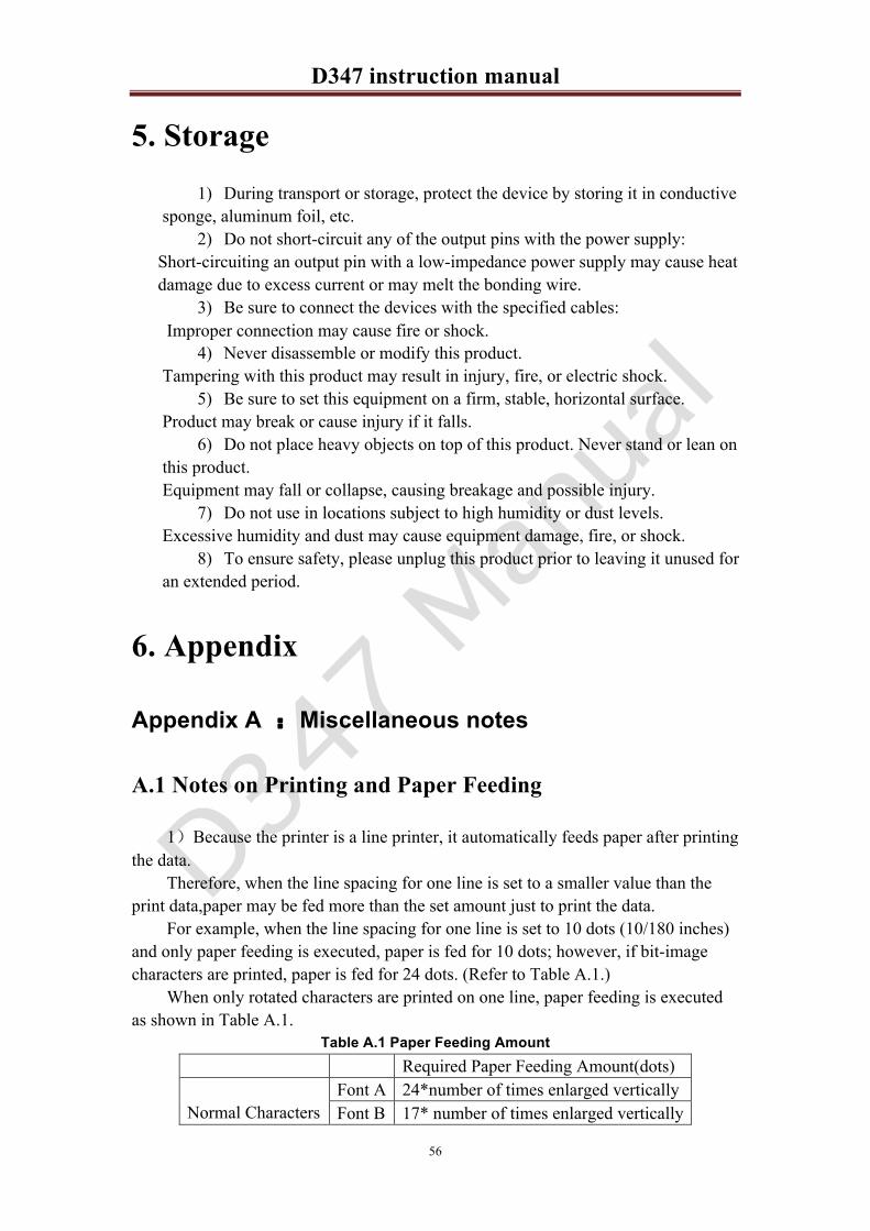
D347 instruction manual!
56
5. Storage 1) During transport or storage, protect the device by storing it in conductive
sponge, aluminum foil, etc. 2) Do not short-circuit any of the output pins with the power supply:
Short-circuiting an output pin with a low-impedance power supply may cause heat damage due to excess current or may melt the bonding wire.
3) Be sure to connect the devices with the specified cables: Improper connection may cause fire or shock.
4) Never disassemble or modify this product. Tampering with this product may result in injury, fire, or electric shock.
5) Be sure to set this equipment on a firm, stable, horizontal surface. Product may break or cause injury if it falls.
6) Do not place heavy objects on top of this product. Never stand or lean on this product. Equipment may fall or collapse, causing breakage and possible injury.
7) Do not use in locations subject to high humidity or dust levels. Excessive humidity and dust may cause equipment damage, fire, or shock.
8) To ensure safety, please unplug this product prior to leaving it unused for an extended period.
6. Appendix
Appendix A �Miscellaneous notes
A.1 Notes on Printing and Paper Feeding
1 Because the printer is a line printer, it automatically feeds paper after printing the data.
Therefore, when the line spacing for one line is set to a smaller value than the print data,paper may be fed more than the set amount just to print the data.
For example, when the line spacing for one line is set to 10 dots (10/180 inches) and only paper feeding is executed, paper is fed for 10 dots; however, if bit-image characters are printed, paper is fed for 24 dots. (Refer to Table A.1.)
When only rotated characters are printed on one line, paper feeding is executed as shown in Table A.1.
Table A.1 Paper Feeding Amount Required Paper Feeding Amount(dots) Normal Characters
Font A 24*number of times enlarged vertically Font B 17* number of times enlarged vertically
D347 instruction manual!
57
Kanji 24* number of times enlarged vertically Rotated Characters
Font A 12* number of times enlarged vertically Font B 9* number of times enlarged vertically Kanji 24* number of times enlarged vertically
Bit image ESC * 24 2 When the printer goes to the standby (data-waiting) state during printing, it
temporarily stops printing and feeding paper. When data is transmitted and printing is executed, paper may shift 1 to 3 dots from the print starting position, which especially affects bit-image printing.
3 Interval of autocutting operation in the receipt section. For driving the autocutter of the receipt section, take the interval as a minimum of 10 lines of printing or paper feeding (to prevent small pieces of cut paper from dropping into the autocutter).
A.2 Notes on Connecting the External Power Supply
Connect the external power supply to the power supply connector of the printer. Then plug in the external power supply and turn it on if necessary. Be sure not to connect the external power supply with the wrong polarity. If it is connected incorrectly, the internal circuit fuse of the printer may be blown, or the external power supply may be damaged.
The power supply voltage is within the range of 24 10% V. If the power supply voltage drops outside of the range above during printing, the printer stops printing and waits until the voltage returns to normal and then automatically begins printing again.
When either a high or low voltage error occurs, turn off the power as soon as possible.
Appendix B �CODE128 BAR CODE
B.1 Description of the CODE128 Bar Code
In CODE128 bar code system, it is possible to represent 128 ASCII characters and 2-digit numerals using one bar code character that is defined by combining one of the 103 bar code characters and 3 code sets. Each code set is used for representing the following characters:
(1) Code set A: ASCII characters 00H to 5FH (2)Code set B: ASCII characters 20H to 7FH (3) Code set C: 2-digit numeral characters using one character (100 numerals
from 00 to 99) The following special characters are also available in CODE128:
(4)SHIFT characters In code set A, the character just after SHIFT is processed as a character for
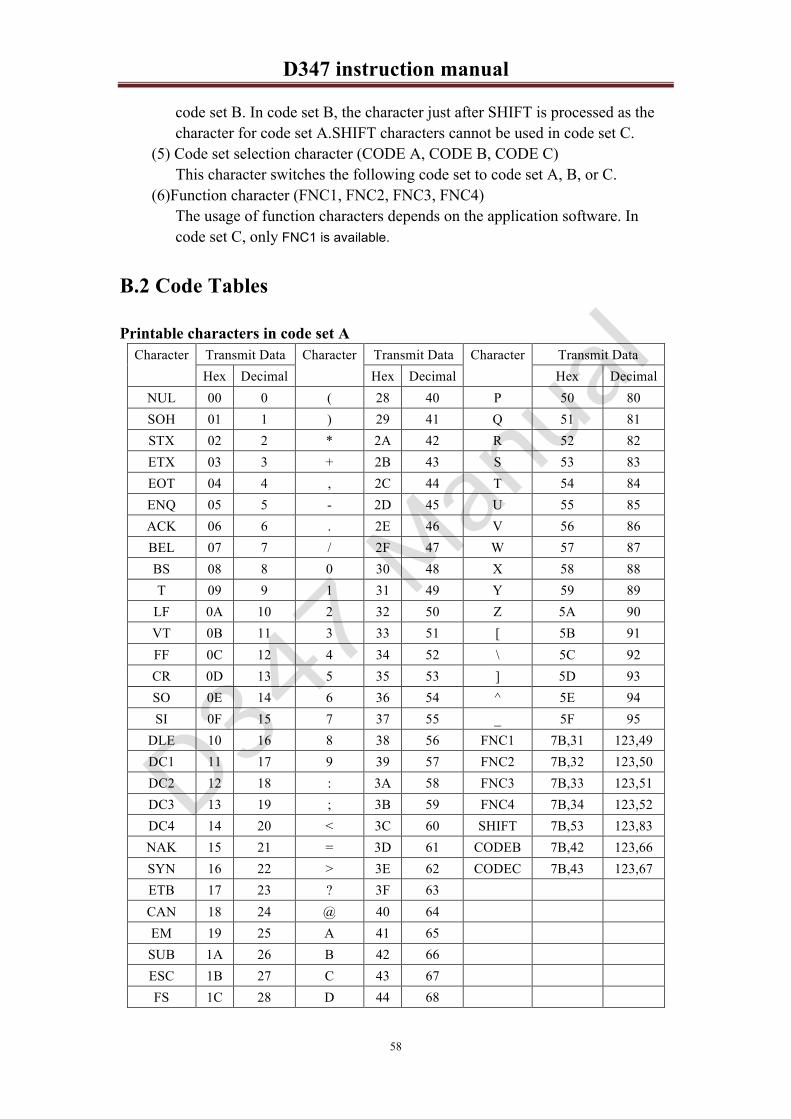
D347 instruction manual!
58
code set B. In code set B, the character just after SHIFT is processed as the character for code set A.SHIFT characters cannot be used in code set C.
(5) Code set selection character (CODE A, CODE B, CODE C) This character switches the following code set to code set A, B, or C.
(6)Function character (FNC1, FNC2, FNC3, FNC4) The usage of function characters depends on the application software. In code set C, only FNC1 is available.
B.2 Code Tables
Printable characters in code set A Character Transmit Data Character Transmit Data Character Transmit Data
Hex Decimal Hex Decimal Hex Decimal NUL 00 0 ( 28 40 P 50 80 SOH 01 1 ) 29 41 Q 51 81 STX 02 2 * 2A 42 R 52 82 ETX 03 3 + 2B 43 S 53 83 EOT 04 4 , 2C 44 T 54 84 ENQ 05 5 - 2D 45 U 55 85 ACK 06 6 . 2E 46 V 56 86 BEL 07 7 / 2F 47 W 57 87 BS 08 8 0 30 48 X 58 88 T 09 9 1 31 49 Y 59 89
LF 0A 10 2 32 50 Z 5A 90 VT 0B 11 3 33 51 [ 5B 91 FF 0C 12 4 34 52 \ 5C 92 CR 0D 13 5 35 53 ] 5D 93 SO 0E 14 6 36 54 ^ 5E 94 SI 0F 15 7 37 55 _ 5F 95
DLE 10 16 8 38 56 FNC1 7B,31 123,49 DC1 11 17 9 39 57 FNC2 7B,32 123,50 DC2 12 18 : 3A 58 FNC3 7B,33 123,51 DC3 13 19 ; 3B 59 FNC4 7B,34 123,52 DC4 14 20 < 3C 60 SHIFT 7B,53 123,83 NAK 15 21 = 3D 61 CODEB 7B,42 123,66 SYN 16 22 > 3E 62 CODEC 7B,43 123,67 ETB 17 23 ? 3F 63 CAN 18 24 @ 40 64 EM 19 25 A 41 65 SUB 1A 26 B 42 66 ESC 1B 27 C 43 67 FS 1C 28 D 44 68

D347 instruction manual!
59
GS 1D 29 E 45 69 RS 1E 30 F 46 70 US 1F 31 G 47 71 SP 20 32 H 48 72 ! 21 33 I 49 73 “ 22 34 J 4A 74 # 23 35 K 4B 75 $ 24 36 L 4C 76 % 25 37 M 4D 77 & 26 38 N 4E 78 ’ 27 39 O 4F 79
Printable characters in code set B Character Transmit Data Character Transmit Data character Transmit Data
Hex Decimal Hex Decimal Hex Decimal SP 20 32 H 48 72 p 70 112 ! 21 33 I 49 73 q 71 113 ” 22 34 J 4A 74 r 72 114 # 23 35 K 4B 75 s 73 115 $ 24 36 L 4C 76 t 74 116 % 25 37 M 4D 77 u 75 117 & 26 38 N 4E 78 v 76 118 ’ 27 39 O 4F 79 w 77 119 ( 28 40 P 50 80 x 78 120 ) 29 41 Q 51 81 y 79 121 * 2A 42 R 52 82 z 7A 122 + 2B 43 S 53 83 { 7B 123 , 2C 44 T 54 84 | 7C 124 _ 2D 45 U 55 85 } 7D 125 . 2E 46 V 56 86 - 7E 126 / 2F 47 W 57 87 DEL 7F 127 0 30 48 X 58 88 FNC1 7B,31 123,49 1 31 49 Y 59 89 FNC2 7B,32 123,50 2 32 50 Z 5A 90 FNC3 7B,33 123,51 3 33 51 [ 5B 91 FNC4 7B,34 123,52 4 34 52 \ 5C 92 SHIFT 7B,53 123,83 5 35 53 ] 5D 93 CODEA 7B,41 123,66 6 36 54 ^ 5E 94 CODEC 7B,43 123,67 7 37 55 _ 5F 95 8 38 56 ` 60 96 9 39 57 a 61 97 : 3A 58 b 62 98 ; 3B 59 c 63 99 < 3C 60 d 64 100

D347 instruction manual!
60
= 3D 61 e 65 101 > 3E 62 f 66 102 ? 3F 63 g 67 103 @ 40 64 h 68 104 A 41 65 i 69 105 B 42 66 j 6A 106 C 43 67 k 6B 107 D 44 68 l 6C 108 E 45 69 m 6D 109 F 46 70 n 6E 110 G 47 71 o 6F 111
Printable characters in code set C character Transmit Data character Transmit Data character Transmit Data
Hex Decimal Hex Decimal Hex Decimal 00 00 0 40 28 40 80 50 80 01 01 1 41 29 41 81 51 81 02 02 2 42 2A 42 82 52 82 03 03 3 43 2B 43 83 53 83 04 04 4 44 2C 44 84 54 84 05 05 5 45 2D 45 85 55 85 06 06 6 46 2E 46 86 56 86 07 07 7 47 2F 47 87 57 87 08 08 8 48 30 48 88 58 88 09 09 9 49 31 49 89 59 89 10 0A 10 50 32 50 90 5A 90 11 0B 11 51 33 51 91 5B 91 12 0C 12 52 34 52 92 5C 92 13 0D 13 53 35 53 93 5D 93 14 0E 14 54 36 54 94 5E 94 15 0F 15 55 37 55 95 5F 95 16 10 16 56 38 56 96 60 96 17 11 17 57 39 57 97 61 97 18 12 18 58 3A 58 98 62 98 19 13 19 59 3B 59 99 63 99 20 14 20 60 3C 60 FNC1 7B,31 123,49 21 15 21 61 3D 61 CODEA 7B,41 123,65 22 16 22 62 3E 62 CODEB 7B,42 123,66 23 17 23 63 3F 63 24 18 24 64 40 64 25 19 25 65 41 65 26 1A 26 66 42 66 27 1B 27 67 43 67 28 1C 28 68 44 68

D347 instruction manual!
61
29 1D 29 69 45 69 30 1E 30 70 46 70 31 1F 31 71 47 71 32 20 32 72 48 72 33 21 33 73 49 73 34 22 34 74 4A 74 35 23 35 75 4B 75 36 24 36 76 4C 76 37 25 37 77 4D 77 38 26 38 78 4E 78 39 27 39 79 4F 79
Appendix C �Switching Online and Offline
The printer changes from offline to online or from online to offline in the following instances: 1�When the power is turned on or during the self-test using the paper FEED button:
The printer is offline between the time when power is turned on (or the printer is
reset) and when the printer is ready to receive data. If ASB (Auto Status Back) is enabled, the printer transmits each status item such
as when an error occurs. When the printer detects a status change with the sensors even if the printer is offline, the printer transmits the ASB.
If the sensor’s status changes while the printer initializes as described above, the printer transmits the offline information with the cause unknown. If this occurs, wait until the printer process a change in the status or the printer comes online. 2�When the self-test is executed(by a command):
The printer goes offline during the self-test. When the self-test is ended, the
printer is reset automatically. When the self-test is executed by a command, the printer does not transmit the
offline information even if the ASB is enabled.

D347 instruction manual!
62
3�While the platen is unloaded(in standby)
If the platen is unloaded in the printer’s standby state, the printer goes offline
(this is not an error). If the platen is loaded again, the printer comes online. If ASB is enabled, the printer transmits each status item each time when an event occurs.
When the printer detects a status change with the sensors, even if the printer is offline, the printer transmits the ASB.
If the sensor’s status changes while paper loading is initialized, the printer transmits the offline information with the cause unknown. (if offline is not caused by an error or a paper-end).
If the offline occurs as a result of a paper near-end, wait until the printer processes a change in status or the printer comes online. 4�While the platen is unloaded(during printing)
If the platen is unloaded during printing, the printer goes offline causing an error.
The printer does not recover from offline only by loading the platen. Transmission of the error recovery command (DLE ENQ) or resetting is also required. 5�When paper is fed with the paper FEED button
The printer is offline when the paper is fed with the paper FEED button. The
printer comes online after the current paper feeding is ended by releasing the paper FEED button.
If ASB (Auto Status Back) is enabled, the printer transmits each status item each time an event occurs.
When the printer detects a status change with the sensors, even if the printer is offline, the printer transmits the ASB. 6�When a paper-end is detected:

D347 instruction manual!
63
If a paper-end is detected, the printer goes offline causing printing to stop (this is
not an error). The printer recovers to online when the printer is ready to receive data, if the
paper loading initialization is finished after the paper is loaded. If ASB (Auto Status Back) is enabled, the printer transmits each status item each
time an event occurs. When the printer detects a status change with the sensors, even if the printer is offline, the printer transmits the ASB.
If a status change is detected by the sensors during paper loading initialization, the printer may go offline without identifying the cause. If this occurs, wait until the status changes or until the printer goes online. 7�When an automatically recoverable error occurs:
When the printer detects an automatically recoverable error, the printer goes
offline. If the printer detects status that can recover automatically, the printer recovers to
online automatically. If ASB is enabled, the printer transmits the ASB when the error occurs. After that, the printer does not transmit ASB again until the printer recovers to online. In this product, a head high temperature error is one of the automatically recoverable errors. 8�When a possibly recoverable error occurs:
When the printer detects a possibly recoverable error, the printer goes offline. When the printer is in the state that can possibly recover to online, the printer
recovers to online by a recoverable error command or resetting the printer. (For the RESET timing, refer to 1) in this section.
If ASB is enabled, the printer transmits the ASB when the error occurs. After then the printer does not transmit the ASB again until the printer recovers to

D347 instruction manual!
64
online. In this product, an autocutter error is one of the possibly recoverable errors.
9�When an unrecoverable error occurs:
When the printer detects an unrecoverable error, the printer goes offline. The
only way to recover from an unrecoverable error is to reset or turn the power off and on again. (If a malfunction causes the error, the printer won’t recover until the printer is fixed.)(For the RESET timing, refer to 1) in this section.)
If ASB is enabled, the printer transmits the ASB when an error occurs. After this, the printer does not transmit the ASB again until the printer recovers to online.
In this product, a high-voltage error is one of the unrecoverable errors. However, when a fatal error, such as a CPU execution error or a memory error, is
detected, the printer won’t transmit the ASB. 10) When the printer goes offline temporarily without any specified cause:
If the printer detects a low voltage temporarily while printing, the printer stops
printing and goes offline without identifying the cause. After the printer detects a normal level of the voltage, the printer comes back
online and starts printing automatically. If the printer detects a low voltage again, the printer sends the low-voltage error status (unrecoverable error).
If the printer goes offline without any identified cause (for an offline not caused by an error or paper-end), when monitoring the printer’s status, it is recommended not to decide the printer status until the printer recovers to online or the printer goes offline with the cause identified (for an offline caused by an error or paper-end).