d1.3 requirements analysis (version 2.0) - dipartimento di ...€¦ · workpad/2008/d1.3/v2.0...
TRANSCRIPT

D1.3 Requirements Analysis(Version 2.0)
Manfred Bortenschlager, Elisabeth Haid, and Hong-LinhTruong (eds.)
with contributions from:A. Faraotti, B. Salvatore, G. Vetere
T. Alamos Miro, J.J. Rodr ıguez GutierrezF. Manti
N. Goll, H. Rieser, R. SteinmannM. Horcic, J. Hytka, Z. Zalis
M. Angelaccio, M. PatrignanelliL. Juszczyk, A. Manzoor
M. de Leoni, A. Marrella, M. Mecella
Abstract.EU STREP project FP6-2005-IST-5-034749 -WORKPAD
Deliverable D1.3v2 (WP1) – This document describes the main part of work-package one (Re-quirements Analysis). This report embodies the second version of this deliverable and presentsthe following contents:(i) a discussion of emergency management case studies,(ii) a detailed usecase descriptions the WORKPAD system intends to address, and (iii) a presentation of require-ments subdivided into a revision of the user requirements and a detailed discussion on systemrequirements.
Copyright c© 2008 TheWORKPAD Consortium
Document Identifier WORKPAD/2008/D1.3/v2.0Project FP6-2005-IST-5-034749Version v2.0Date 30.03.2008State FINAL
Distribution PUBLIC

WORKPAD Consortium
This document is part of a research project funded by the IST Programme of the Commission of the European Com-munities as project number FP6-2005-IST-5-034749.
Universita degli Studi di Roma “La Sapienza”CoordinatorDipartimento di Informatica e Sistemistica“Antonio Ruberti”Via Salaria 11300198 RomaITALYContact persons:Tiziana Catarci, Massimo MecellaE-mail address:{catarci,mecella}@dis.uniroma1.it
Technische Universitæt WienInstitute fur InformationssystemeArgentinierstrasse 81040 WienAUSTRIAContact person:Schahram DustdarE-mail address:[email protected]
Universita degli Studi di Roma “Tor Vergata”Dipartimento di Informatica, Sistemi e ProduzioneVia del Politecnico 100133 RomaITALYContact person:Michele AngelaccioE-mail address:[email protected]
APIF Moviquity S.A.R&D DepartmentIsabel de Colbrand 10, Planta 5a, Oficina 15028050 MadridSPAINContact person:Carlos PradesE-mail address:[email protected]
IBM Italia S.p.A.IBM Rome Center for Advanced StudiesVia Sciangai 5300144 RomaITALYContact person:Guido VetereE-mail address:[email protected]
Software602Hornokrcska 15140 21 Praha 4CZECH REPUBLICContact person:Zdenek M. ZalisE-mail address:[email protected]
Salzburg Research Forschungsgesellschaft m.b.h.Jakob Haringer Strasse 5/III5020 SalzburgAUSTRIAContact person:Manfred BortenschlagerE-mail address:[email protected]
Regione Calabria - Settore Protezione CivileCentro FunzionaleVia F. Crispi 1988100 CatanzaroITALYContact person:Giuseppe IiritanoE-mail address:[email protected]

Changes
Version Date Author Changes2.0 30.03.08 SRFG First official edition of second version of
D1.3Distributed to Project Officers

Executive Summary
The WORKPAD project aims at investigating and developing an adaptive peer-to-peersoftware infrastructure for supporting collaborative work of human operators in emergen-cy/disaster scenarios. In such scenarios, different teams, belonging to different organisa-tions, need to collaborate in order to reach a common goal.
This deliverable report presents the second iteration of the requirements deliverableD1.3. There will be a third version of this deliverable due tothe iterative approach takenin the WORKPAD project. This version essentially deals with analysinguserandsystemrequirements. This required a high degree of involvement ofusers (for the user require-ments) on the one hand but on the other, also intensive discussions with the technicalpartners regarding elicitation, definition, interdependency, and realisation of system re-quirements. System requirements were derived from user requirements, use case analysis,and experience of system and component engineers.
The structure of the report can be summarized as follows:
• Section 1 introduces the objectives, structure, purpose ofthis deliverable and alsothe relationship to other WORKPAD work-packages and deliverables.
• Section 2 analysis three case studies of facets of implemented emergency manage-ment systems in the EU: Austria, Czech Republic, and Spain.
• Section 3 covers the adopted requirements elicitation methodology describing theconducted requirements engineering activities and the techniques deployed. It alsoreviews the methodology regarding the slight amendments with respect to the method-ology deployed in the first version of D1.3.
• Section 4 provides a detailed discussion of use cases the WORKPAD system covers.This parts starts with high-level system-wide use cases andcontinues with detaileduse cases on a component-basis.
• Section 5 presents the elicited requirements separated into user and system require-ments and addresses performance issues.
• Section 6 summarises this deliverable.

Contents
1 Introduction 11.1 Purpose and Structure of the Document . . . . . . . . . . . . . . . .. . 11.2 Relationship to Other Deliverables . . . . . . . . . . . . . . . . . .. . . 2
2 Emergency Management in Europe: Case Studies 42.1 Emergency Management in Austria . . . . . . . . . . . . . . . . . . . .42.2 Emergency Management in the Czech Republic . . . . . . . . . . . . .. 8
2.2.1 Law Regulation . . . . . . . . . . . . . . . . . . . . . . . . . . . 82.2.2 Early Warning System in the Czech Republic . . . . . . . . . . . 102.2.3 Fire Rescue Service . . . . . . . . . . . . . . . . . . . . . . . . . 122.2.4 First Medical Aid . . . . . . . . . . . . . . . . . . . . . . . . . . 142.2.5 Main Well Control Service Rescue Corps . . . . . . . . . . . . . 162.2.6 Emergency Call Centres . . . . . . . . . . . . . . . . . . . . . . 162.2.7 Air Rescue of the Czech Police . . . . . . . . . . . . . . . . . . 17
2.3 Emergency Management in Spain . . . . . . . . . . . . . . . . . . . . . 182.3.1 Civil Protection in Spain . . . . . . . . . . . . . . . . . . . . . . 182.3.2 Spanish Emergency Organisations Hierarchy . . . . . . . .. . . 192.3.3 Example Descriptions of Involved Organisations . . . .. . . . . 19
2.4 Conclusions from the EM Case Studies . . . . . . . . . . . . . . . . . . 24
3 Methodology 263.1 Requirements Engineering Process . . . . . . . . . . . . . . . . . . .. . 263.2 An Overview of the Adopted Methodology . . . . . . . . . . . . . . .. 28
4 Use Case Descriptions 334.1 Worklist Handler . . . . . . . . . . . . . . . . . . . . . . . . . . . . . . 36
4.1.1 Worklist Handler Component . . . . . . . . . . . . . . . . . . . 374.1.2 Context Monitoring and Management Framework - RelevantUse
Cases for the Worklist Handler Component . . . . . . . . . . . . 404.1.3 Process Management System - aPMS . . . . . . . . . . . . . . . 444.1.4 Mobile Ad Hoc Network - Relevant Use Cases for the Worklist
Handler . . . . . . . . . . . . . . . . . . . . . . . . . . . . . . . 544.2 GIS Front-End . . . . . . . . . . . . . . . . . . . . . . . . . . . . . . . 57
4.2.1 GIS Front-End Module . . . . . . . . . . . . . . . . . . . . . . . 58
iii

CONTENTS
4.2.2 Context Monitoring and Management Framework - RelevantUseCases for the GIS Front-End Module . . . . . . . . . . . . . . . 69
4.2.3 Mobile Ad Hoc Network - Relevant Use Cases for the GIS Front-End Module . . . . . . . . . . . . . . . . . . . . . . . . . . . . . 73
4.2.4 GIS Back-End Module- Relevant Use Cases for the GIS Front-End Module . . . . . . . . . . . . . . . . . . . . . . . . . . . . . 73
4.3 Lightweight Storage . . . . . . . . . . . . . . . . . . . . . . . . . . . . . 744.3.1 Lightweight Storage Component . . . . . . . . . . . . . . . . . . 744.3.2 Mobile Ad Hoc Network - Relevant Use Cases for the Lightweight
Storage . . . . . . . . . . . . . . . . . . . . . . . . . . . . . . . 824.3.3 Multimedia Editor - Relevant Use Cases for the Lightweight Storage 82
4.4 Multimedia Editor . . . . . . . . . . . . . . . . . . . . . . . . . . . . . . 824.4.1 Use Case Descriptions . . . . . . . . . . . . . . . . . . . . . . . 82
4.5 MANET Configuration . . . . . . . . . . . . . . . . . . . . . . . . . . . 884.6 Context Editor . . . . . . . . . . . . . . . . . . . . . . . . . . . . . . . . 88
4.6.1 Use Case Descriptions . . . . . . . . . . . . . . . . . . . . . . . 894.6.2 Context Monitoring and Management Framework - RelevantUse
Cases for the Context Editor . . . . . . . . . . . . . . . . . . . . 984.7 Process Management-UI . . . . . . . . . . . . . . . . . . . . . . . . . . 984.8 GIS Back-End . . . . . . . . . . . . . . . . . . . . . . . . . . . . . . . . 103
4.8.1 GIS Back-End Module . . . . . . . . . . . . . . . . . . . . . . . 1034.8.2 P2P Data Integration System - Relevant Use Cases for the GIS
Back-End . . . . . . . . . . . . . . . . . . . . . . . . . . . . . . 1164.9 Peer-to-Peer Data Integration System . . . . . . . . . . . . . . .. . . . . 116
5 Requirements 1295.1 User Requirements . . . . . . . . . . . . . . . . . . . . . . . . . . . . . 129
5.1.1 General User Requirements (G) . . . . . . . . . . . . . . . . . . 1305.1.2 Communication (C) . . . . . . . . . . . . . . . . . . . . . . . . 1345.1.3 Back-End (B) . . . . . . . . . . . . . . . . . . . . . . . . . . . . 1355.1.4 Front-End (F) . . . . . . . . . . . . . . . . . . . . . . . . . . . . 138
5.2 System Requirements . . . . . . . . . . . . . . . . . . . . . . . . . . . . 1425.2.1 Worklist Handler – WH . . . . . . . . . . . . . . . . . . . . . . 1425.2.2 Context Monitoring and Management Framework – CMMF . . . 1445.2.3 The MANET Management . . . . . . . . . . . . . . . . . . . . . 1465.2.4 Adaptive Process Management System – aPMS . . . . . . . . . .1505.2.5 GIS Front-End – GIS-FE . . . . . . . . . . . . . . . . . . . . . . 1535.2.6 Leightweight Storage – LS . . . . . . . . . . . . . . . . . . . . . 1625.2.7 Multimedia Editor – MME . . . . . . . . . . . . . . . . . . . . . 1655.2.8 Context Editor – CE . . . . . . . . . . . . . . . . . . . . . . . . 1675.2.9 Process Miner – PM . . . . . . . . . . . . . . . . . . . . . . . . 1695.2.10 GIS Back-End – GIS-BE . . . . . . . . . . . . . . . . . . . . . . 1705.2.11 P2P Data Integration – DI . . . . . . . . . . . . . . . . . . . . . 1745.2.12 System Requirements from D1.3v1 . . . . . . . . . . . . . . . . 182
5.3 Performance Considerations for WORKPAD Components . . . . . .. . 183
iv 30.03.2008 WORKPAD/2008/D1.3/v2.0

D1.3 Requirements Analysis(Version 2.0) Project FP6-2005-IST-5-034749
5.3.1 Objectives of the Performance Analysis . . . . . . . . . . . .. . 1835.3.2 Main Component Dependencies and Data Flows . . . . . . . . . 1835.3.3 Survey of Performance Perceptions from Users and Developers . 1865.3.4 Generating Test Cases . . . . . . . . . . . . . . . . . . . . . . . 186
6 Summary 189
WORKPAD/2008/D1.3/v2.0 30.03.2008 v

Chapter 1
Introduction
“Requirements Analysis” is the title of this second version of deliverable D1.3. This de-liverable summarises the main works conducted in work-package 1 (Requirements Anal-ysis). Work-package 1 fine-tunes the overall work program and provides a detailed listingof requirements relevant for the WORKPAD system.
The document D1.3v2 contains the following main parts:
1. A further discussion of emergency management case studies in Austria, Czech Re-public, and Spain (Section 2)
2. A detailed use case descriptions the WORKPAD system intends to address (Section4)
3. A presentation of requirements subdivided into a revision of the user requirementsand a detailed discussion on system requirements. In addition, performance consid-erations are provided. (Section 5)
The following two sub-sections define the purpose and structure of the document andthe relation to other deliverables of the WORKPAD project.
1.1 Purpose and Structure of the Document
Due to the organization of phases in the WORKPAD project, three iterations during thesystem engineering process are conducted. Consequently, the requirements analysis alsoiterates three times, too resulting in three versions of thedeliverable D1.3, which areproduced according to the following planned schedule:
• Version 1 in project month 6
• Version 2 in project month 18
1

1. INTRODUCTION
• Version 3 in project month 30
Version 1 of the deliverable D1.3 entitled “Requirements andConceptual Analysis”was finished and submitted [WOR07a]. The second version at hand has a different title:“Requirements Analysis”. The first version covered also a first high-level analysis of theintended architecture and its main and necessary building blocks. This second versionof D1.3 roughly follows a similar structure but does not cover architectural issues. Dueto the progress of the WORKPAD project other work-packages and deliverables specifi-cally deal with the system architecture (see [WOR07b, WOR08a]), which should not berepeated here. Instead, we refer to these other documents when appropriate.
Although, all three versions of the deliverable D1.3 are structured similarly, each onehas a different focus. With progression of the WORKPAD project the quantity and pre-sumably the quality—due to the revision cycles—shall increase over time. The purposeof this document (D1.3 version 2.0) is to further (re-)definethe requirements for WORK-PAD and continue in the chosen methodology of the engineering process (see also Figure3.2 in Section 3 “Methodology”) with the next steps. D1.3v1 covered the steps frominitial user group definition up to hierarchical task analysis (HTA) and requirements anal-ysis. D3.1v2 reviews the requirements defined in the first version, refines them furtherand adds additional classifications. Furthermore, use cases are discussed that cover therequirements and based on that the resulting system components are elaborated in theaccording architecture deliverables ([WOR07b, WOR08a]).
The high-level structure of deliverable D1.3v2 consists ofthe following main parts:
• Section 2 gives details about the conducted case study analysis.
• Section 3 presents an updated version of the adopted methodology to engineer anddesign the WORKPAD system.
• Section 4 contains the use case descriptions starting out from a overall WORKPADsystem perspective followed by a details analysis of the usecases of each systemcomponent.
• Section 5 presents the requirements revised from the first version of D1.3 and sub-sequently conducts a clear separation between user- and system requirements. Thissection covers also performance issues relevant for the WORKPAD system.
• Section 6 summarises the main objectives and outcomes of this deliverable docu-ment D1.3v2.
1.2 Relationship to Other Deliverables
This document D1.3v2 is related to the following WORKPAD deliverables:
2 30.03.2008 WORKPAD/2008/D1.3/v2.0

D1.3 Requirements Analysis(Version 2.0) Project FP6-2005-IST-5-034749
• WORKPAD D1.3: Requirements and Conceptual Analysis, Version 1.0 (PU, pub-lic deliverable) [WOR07a]: This document is the predecessorof the D1.3v2 andpresents initial analysis and requirements elicitation results, which are taken as thebasis for this second version.
• WORKPAD D2.1: The WORKPAD Architecture (PU, public deliverable)[WOR07b]: This deliverable defines the conceptual and technical architecture ofthe WORKPAD infrastructure in more details and uses D1.3 as input and as a ba-sis. The main building blocks for the initial conceptual architecture are describedin D1.3v1.
• WORKPAD D3.1: Architecture and Detailed Design for the Front-end (PU, publicdeliverable) [WOR08a]: This deliverable provides the detail system design of thefront-end components of the WORKPAD system based on the system requirementsdefined in D1.3v2.
• WORKPAD D3.2: Basic Algorithms, Methods and Techniques for the Front-end(RE, restricted deliverable) [WOR08b]: This deliverable gives concrete descrip-tions about algorithms and techniques adopted in the front-end to fulfil the require-ments.
• WORKPAD D4.1: Architecture and Detailed Design for the Back-end (PU, publicdeliverable) [WOR08c]: This deliverable provides the detail system design of theback-end components of the WORKPAD system based on the systemrequirementsdefined in D1.3v2.
• WORKPAD D4.2: Basic Algorithms, Methods and Techniques for the Back-end(RE, restricted deliverable) [WOR08d]: This deliverable gives concrete descrip-tions about algorithms and techniques adopted in the back-end to fulfil the require-ments.
• WORKPAD D6.1: WORKPAD Showcases Design and Implementation (PP, re-stricted to other program participants) [WOR08e]: In this deliverable D6.1, theWORKPAD showcases and demo will be defined. This also includesthe defini-tion of demo specific requirements as a subset of the D1.3v2 requirements. Hence,the requirements listed in this document D1.3 serve as first input for the showcaserequirements elicitation.
• WORKPAD D6.2 Report on the Validation Activity (RE, restricteddeliverable)[WOR08f]: This document describes the results of various validation activities per-formed during the project WORKPAD. This also includes requirement validationactivities based on the requirements gathered in D1.3v2.
WORKPAD/2008/D1.3/v2.0 30.03.2008 3

Chapter 2
Emergency Management in Europe:Case Studies
D1.3 version 1.0 (Section 5) already discussed the case study example of the Italian re-gion Calabria. In this section we investigated the national regulations and processes withrespect to emergency management of three other European countries: Austria, CzechRepublic, and Spain1. This analysis is more a detailed study than the one already pro-vided in D1.3v1 Section 3.3 and resulted in a better understanding of emergency man-agement itself and how implementations look like on different national levels. This has adirect influence on choosing and specifying requirements for EU emergency managementsystems—such as WORKPAD.
2.1 Emergency Management in Austria
Emergency management in Austria is defined under the term “civil protection”. Civilprotection is defined as the sum total of all preventive measures and activities designedto enable the population to survive in any type of crisis situation. Therefore civil protec-tion includes all humanitarian activities to manage emergencies and other major catastro-phes. It includes prevention actions against natural or technical disasters, accidents in thechemical industry as well as accidents during the transportof hazardous goods or nuclearincidents.
In Austria civil protection must be seen as a multi-purpose system to prevent disastersand provide aid at such situations. This process is embeddedin the joint responsibilitycarried by the authorities at the federal, provincial, district and local level and by differentrelief organisations. Austria has nine provinces (Bundeslaender) with his own parliamentand government and is led by a provincial governor. In a legalview the civil protectionis regulated by law of each of the nine provinces under the term of disaster management
1These three countries have been chosen because the WORKPAD partners are originating from thesecountries.
4

D1.3 Requirements Analysis(Version 2.0) Project FP6-2005-IST-5-034749
[Tir06, Sal75, e.g.]. In the legal framework the preventionand relief activities are regu-lated. The prevention tasks include the compilation of emergency plans on local, districtand provincial level, the definition of the director of operations on the different levels, andthe exercises of all participating teams. The relief activities describe all relevant tasks tocoordinate the different teams to cope an emergency.
Following we present a short overview of the different instances and their generaltasks of the Austrian civil protection system.
1. Federal Ministry of the Interior
• Coordinate national crisis and disaster management
• International contact point
• Nation wide warning and alerting system
2. 9 Provinces
• Provide legal framework (e.g. disaster management, fire brigades)
• Manage large scale disasters
3. 99 District administrative units
• Main disaster management authority
• Manage regional disasters
4. 2359 Municipalities
• Provide resources and set up rescue services and fire brigades
• Manage local disasters
Description of the main hierarchy
Each municipality provides resources for the prevention and rescue activities in case ofan emergency. If an emergency occurs which affect only the local area the mayor and thefire brigade is responsible for coordinating the rescue activities.
If the emergency affects a bigger area, which is affecting the district, then the headof the district administrative unit is the director of operations for the relief activities. Forthe WORKPAD scenarios this level of the Austrian civil protection system is the mostimportant one. For this reason we will have a closer look to the processes on the districtlevel. In Figure2.1 the organisational structure of the district level is described.
The director of operations is responsible for the whole emergency operation. He issupported from the mission staff which has the function to advise and assist the directorof operations with his decisions. The mission staff is structured in a Management Team,
WORKPAD/2008/D1.3/v2.0 30.03.2008 5

2. EMERGENCY MANAGEMENT IN EUROPE: CASE STUDIES
Figure 2.1: Emergency Organisation Chart at District Level [Sal97]
and a Functional Group. Additionally to the mission staff a Reporting Office supports thedirector of operations.
The Management Team, which must be available at all different kinds of emergencies,is subdivided in five functional areas (S1-S5), which have following tasks:
1. Workforce Unit (S1)
• Personnel planning and administration
• Connection to other authorities
• Work on legal concerns
2. Emergency Situation Unit (S2)
• Acquisition of data of the emergency situation
• Evaluation of the emergency situation
• Generation of the emergency situation map and the emergencyjournal
3. Emergency Coordination Unit (S3)
• Working directly with the director of operations
• Coordination of the whole rescue operation
• Evaluation of the whole emergency situation and preparation of the next tasksfor the director of operations
• Coordination the work of the mission staff
4. Logistics Unit (S4)
• Emergency equipment planning and administration
6 30.03.2008 WORKPAD/2008/D1.3/v2.0

D1.3 Requirements Analysis(Version 2.0) Project FP6-2005-IST-5-034749
• Catering for the whole emergency response team
5. Publicity Unit (S5)
• Work on press and media releases (always on agreement with the director ofoperations)
The composition of the Functional Group depends on the type of the emergency.Members could be liaison officers of the different emergencyunits (fire brigade, am-bulance services, executive authority, federal army and special ambulance services),which are authorised to make decisions, technical experts,several infrastructure opera-tors (telecommunication, power supply, roads and railways) and other important decisionmakers which are affected by the emergency. The task of the Reporting Office is to collectthe incoming and outgoing reports and to protocol the whole activities of the emergencyoperation.
If the emergency affects more than one district the provincial government is responsi-ble for the coordination of the response activities. In thiscase the government get assis-tance from the provincial alarm centre. Moreover the provincial alarm centre is responsi-ble for the information of the population and is the link to the federal alarm centre.
The Federal Alarm Center is installed in the Federal Ministryof the Interior and hasfollowing tasks and functions in the emergency management process in Austria:
1. Tasks within the warning and alerting system
• to recognize hazardous situations
• to give out warnings and alerts
• to coordinate tasks in disaster prevention
• to become active within supraregional and international disaster relief
2. Actor as contact point in bilateral and multilateral disaster relief and radiation pro-tection
• reporting on incidents and accidents
• reporting on occurrences that may generate anxiety in the population
• ways of cooperation and
• possible assistance in the case of a disaster
3. Tasks in a supraregional or international disaster or crises
• reporting, coordinating and liaison point for the provincial alarm centers
• central information exchange between all bodies concernedin Austria andabroad (e.g. Monitoring and Information Center (MIC) of the EuropeanUnion)
• message relay centre for the National Crises Management Boardin case ofcrises
WORKPAD/2008/D1.3/v2.0 30.03.2008 7

2. EMERGENCY MANAGEMENT IN EUROPE: CASE STUDIES
Description of the involved institutions/organisations
In contrast to other countries, Austria has no special emergency management units. Nextto the administrative bodies on the different levels (province, district, and local) which areresponsible for the emergency management process (as described above for the districtlevel) different rescue units are involved in this process.In particular, these are the firefighting squads, the Austrian Red Cross, different ambulance services and the MountainRescue Service. Altogether, some 300,000 well-trained and optimally equipped men andwomen (about 4% of the population) are available. In the mostinstances these are peoplewhich make their work as volunteer. Their activities are of great importance for civilprotection in Austria. Furthermore efficient emergency management would be impossiblewithout the assistance of the law enforcement units and the Federal Army who play alsoa key role in the emergency management.
2.2 Emergency Management in the Czech Republic
This section presents the integrated rescue system of the Czech Republic [ZN03]. TheGovernment is the supreme executive body implementing the national security policy. Itis responsible for the management and operational capability of the entire security system.It has the power to declare the state of emergency in case of a serious crisis that posesconsiderable danger to life, health, property or to internal order and security. Subject toconditions laid down by law, the Government can decide on thedeployment of the armedforces outside the Czech Republics territory and on the presence of foreign armed forcesin the territory of the Czech Republic, provided that the period of such deployment orpresence does not exceed 60 days.
2.2.1 Law Regulation
The legal basis of the Integrated Rescue System (IZS) is defined by three significant leg-islative norms
1. Act on Fire Prevention
2. Act on the Czech Fire Rescue Brigade
3. Act on the Procedure of Crisis and the Integrated Rescue System (IZS)
Whilst the Act on Fire Prevention defines the categories of thefire prevention, andregulates professional ability of authorized workers (technicians, prevention workers),defines supervision bodies and their activities as well as the activity of communities andlocal authorities in the sphere of fire prevention – the Act onFire Rescue Brigade of theCzech Republic specifies the role of the fire prevention and citizens’ protection regulatingthe position and organization of the Fire Brigade, defines theinterconnection of the legal
8 30.03.2008 WORKPAD/2008/D1.3/v2.0

D1.3 Requirements Analysis(Version 2.0) Project FP6-2005-IST-5-034749
regulation with the prepared legal norm on the procedure of crisis and also regulates theemployees’ relations identically with those of the membersof other security bodies (as aregular employment). The Act of the Czech Fire Rescue Brigade links up with IZS andthe Act on the Procedure of Crisis.
The Act on the Procedure of Crisis is the basic tool of the stateadministration con-sisting of two parts. Part 1 defines basic terms, lays down theactivity of the bodies of theprocedure of crisis and measures to be taken together with that of the integrated rescuesystem, regulates the obligations of legal and natural persons and also specifies the prin-ciples of carrying out checks and imposing fines. Part 2 relates to the amendments of theacts in force.
The Act on the Procedure of Crisis and the Integrated Rescue System is an applicationAct to the Constitutional Act No. 110/1998 Dig. on Security ofthe Czech Republic, ofwhich the Art. 3 is of an extraordinary importance. Art. 1 lays down that sovereigntyand territorial integrity, protection of democratic principles and lives, health and propertyare the basic obligations of the state. This is regulated by Art. 9 by which the StateSecurity Council (BRS) is established and the government is empowered to define theextent of BRS authorization for preparing a draft of the measures to be taken to providethe security of the Czech Republic.
As far as competences are concerned, the Authority of the state administration is theMinistry of the Interior [Cze08b] of the Czech Republic which manages BRS - a Boardfor Emergency Planning. In a similar way the Ministry of Defence manages the Boardof Defence Planning and the Board of Coordination Foreign Security Policy is directlysubordinated to the Ministry of Foreign Affairs [Min08a]. The Administration of StateMaterial Reserves (SSHR) cares for economy and takes economicmeasures in case of thesituations of crisis in accordance with Act No. 97/1993 Dig.on the activities of SSHR inthe wording of the Act No. 272/1998 Dig.
Fire and Rescue Service of Czech Republic fulfils tasks in the scope and under condi-tions determined by specific legal regulations, mainly by:
• Law No. 133/1985 on fire protection, in latter wording
• Law No. 238/2000 on Fire Rescue Service of CR and on the modification of certaincodes, in latter wording
• Law No. 239/2000 on Integrated Rescue System and on the modification of certaincodes, in latter wording
• Law No. 240/2000 on Crisis Management and on the modification of certain codes(Crisis Code), in latter wording.
The Integrated Rescue System was approved as early as in 1993 by the GovernmentalDecree No. 246/1993 Dig. together with its principles attached herewith. The IZS isdefined as a system providing a coordinated procedure of rescue, emergency, professional
WORKPAD/2008/D1.3/v2.0 30.03.2008 9

2. EMERGENCY MANAGEMENT IN EUROPE: CASE STUDIES
and other services, state administration and self-government bodies, natural and legalpersons during liquidation of disasters.
Basic sections which are in a non-stop emergency to announce disaster and to inter-vene quickly in the place of the disaster are Fire Rescue Brigade (HZS), Medical RescueService and Czech Police. Based on the character and extent of the disaster IZS has somemore services at its disposal (in particular Civil Defence (CO), hygienic service, miningrescue service, air rescue service etc). IZS operation and information centre is incor-porated in the operation centre HZS, keeps documentation and records of IZS activity,accepts and evaluates information about disasters, fulfilsorganizational and some moretasks within IZS.
Let us add that the Act on Crisis will be followed by lots of application norms, inparticular governmental decrees and notices of the Ministry of the Interior. They willrelate for instance to the activities and structure of security councils and staffs of crisis,formalities of the plans of crisis and establishment of the workplaces of crisis, principlesof coordination of IZS sections during a common intervention and also principles of theso-called communication of crisis. Decrees dealing with informing citizens in case ofannouncing situations of crisis and also decrees relating to maintenance and renewal ofworks on roads, public telecommunication networks etc. areof great importance. Fur-ther application norms will also include principles of providing extraordinary financialassistance to natural persons and communities from the state budget during crashes ornatural disasters as well as settling CO expenses. Finally extraordinary attention is drawnto the principles of planning preparatory measures and those of crisis providing economicoperation in industry and trade.
2.2.2 Early Warning System in the Czech Republic
As the most dangerous type of natural disaster in the Czech Republic or in Central Eu-rope in general has always been flood the Early Warning Systemused at the end of 1999year is demonstrated on this kind of disaster. According to the Czech law a responsiblebody for flood warning in CR has been the Czech Hydrometeorological Institute (CHMI)[Cze08a] in co-operation with River Basin Boards. However, floodwarnings are passedfurther with the help of the Main Office of Civil Defence and theMain Centre of Fire Pro-tection Service to other levels like communities, districts and other administrative bodiesin accordance with flood planning and under a supervision of Flood Authorities (see Fig-ure 2.2).
Central Flood Authority operated by the Ministry of Environment is always warneddirectly from CHMI. It can be seen that the system ensures delivery of warning up tolocal levels where an newly built Integrated Rescue System (IRS) will be used with anadvantage. Flood Authorities are under certain condition integral parts of crisis staffs atall levels and also main responsibility for all kind of critical situations on the state levelwill be transferred to the Ministry of Interior.
The main purpose of the flood warning and forecasting system is forecasting of flood
10 30.03.2008 WORKPAD/2008/D1.3/v2.0

D1.3 Requirements Analysis(Version 2.0) Project FP6-2005-IST-5-034749
Figure 2.2: Flood Forecasting and Warning System in the CzechRepublic (adapted from[Cze08a])
activity at various levels of flood danger with a sufficient lead time on rivers in the CzechRepublic. Forecasts and warnings are used for timely information of flood authorities,River Board dispatchers, and property owners and also for warning of population andinstitutions responsible for people safety. However, in the urgent cases of flood dangerand necessary to warn population in regions very quickly warnings from CHMI can bepassed directly to people by means of public radio, television, Internet and other media.This possibility has been included in agreements between CHMI and above mentionedmedia. Organization of flood forecasting and warning service in CHMI involving CentralForecasting (CFO) and 6 Regional Forecasting (RFO) Offices is shown in Figure 2.3.
This integrated Flood Forecasting and Warning System operated by CHMI (nationalhydrometeorological service) is based on a multi-sensor observation input (precipitation,river flow etc.) containing modern observational instruments like weather radars and satel-lites. Moreover, the system will use routinely numerical weather models to be able toforecast heavy precipitation and consequent floods with longer lead time. Very importantis also hydrological part utilizing hydrological models and potentially GIS images in thelast stage. Development of hydrometeorological part of thesystem has been coordinatedwith activities of River Basin Boards and also in a co-operationwith specialists from othercountries especially USA, Denmark and Netherlands.
Similar Early Warning System has also been applied to other hydrometeorologicalrisks (severe storms, frosts and other weather extremes) and also in the case of predictionsand warnings for smog situations [Obr06]. The Czech Republic has also built a specialwarning system used in the case of nuclear accidents - in thiscase the State Office forNuclear Safety has been the highest competent authority. The system utilizes results ofa continuous measurement radioactivity network together with predictions of trajectories
WORKPAD/2008/D1.3/v2.0 30.03.2008 11

2. EMERGENCY MANAGEMENT IN EUROPE: CASE STUDIES
Figure 2.3: Integrated Flood Forecasting and Warning System in CHMI (adapted from[Cze08a])
and contamination dispersion. Results of radioactivity measurements and also warningshave been continuously disseminated to neighbouring countries.
Finally, it is necessary to mention another important factor - training of populationto react properly under emergency situations like floods. According to experience fromthe last large flood in 1997 year the lack of training and poor knowledge of people aboutproper behavior and response under flood conditions had a strong influence on number ofvictims during this event.
2.2.3 Fire Rescue Service
Fire Rescue Service [Gen08] of the Czech Republic is one of the basic bodies of Inte-grated Rescue System, which has been operating with new structure since January 1st,2001. Primary mission of Fire Rescue Service of CR is to protectlife, health and prop-erty of citizens against fire and to provide effective help inemergencies. By the Law No.238/2000 on Fire Rescue Service of CR and on certain regulations, a new organizationalstructure had been established and the basic tasks had been determined.
Fire Rescue Service of CR consists of General Directorate of Fire Rescue Service ofCR, which is a part of Ministry of Interior, and of Regional Fire Rescue Services. GeneralDirectorate of Fire Rescue Service of CR controls the Regional Fire Rescue Services,which are state organizational bodies and accounting unitsas well. Tasks of Fire RescueService of CR are fulfilled by members of Fire Rescue Service of CR(under the Law onfunctional relation of members of Czech Police Corps), by civil servants (under the CivilService Law) and by other employees (see also Figure 2.4).
12 30.03.2008 WORKPAD/2008/D1.3/v2.0

D1.3 Requirements Analysis(Version 2.0) Project FP6-2005-IST-5-034749
Figure 2.4: Structure of the Fire Rescue Service (adapted from [Gen08])
WORKPAD/2008/D1.3/v2.0 30.03.2008 13

2. EMERGENCY MANAGEMENT IN EUROPE: CASE STUDIES
2.2.4 First Medical Aid
In the Czech Republic, the system of modern rescue service has achieved considerablelevel of efficiency in the years before the terrible terrorist attacks in the USA on September11th 2001. After significant efforts of physicians active inthe Emergency Medical Service(EMS) by the end of 90ties, important steps ahead were achieved in the legislative basisas well as in the technological and personal equipment, in monitoring and in operationalmanagement of the EMS.
In 1998 Minister of Health has established Emergency Medicine (EM) as a highermedical specialization [Min08b]. Consequently, the past Chair for Prehospital Immedi-ate Care and Disaster Medicine in the Institute for Postgraduate Medical Education inPrague has been renamed as the Chair for Emergency and Disaster Medicine. EmergencyMedicine is the only one of our medical specializations containing integral chapters fromdisaster medicine. Immediately, the Czech Republic started the specialization educa-tion of physicians (so far 220 physicians have achieved the specialization degree in EM).Furthermore, courses of continuous education for specialists in Emergency Medicine areperiodically organized. And, more to this, the Czech Republichad initiated and offeredFirst Aid training program in order to achieve higher level of knowledge and skills infirst aid among physicians. Consequently, in 2001 the Ministry of Health has decidedthat all physicians have to pass successfully our First Aid course and training before theiradmission to the examination in elected specialization (first degree).
By the end of 2000, three basic laws related to disaster situations (on Integrated Res-cue System, on Crisis Management and on Economical Measures for Crisis States) wereissued. In July 2000, during floods from rivers swollen by heavy rains on the territory ofthe Czech Republic, the largest floods in our known history, allrescue capacities of thecountry have passed an enormous test.
The flood disaster has started in southern Bohemia. During following days, perma-nently increasing masses of water in the river Vltava /Moldau/ have moved to the North,to Prague and later on to the confluence of the river Vltava /Moldau/ with the river Labe/Elbe/. The flow of water in Prague has reached the maximum of 5500 cubic meters persecond - when compared to the normal value of 150 cubic metersmore than 36 times!
According to the report of the Ministry for Local Development, as issued on August28th 2000, 505 localities placed in 31 districts with 1 600 000 citizens were floodedtotally or partially (see picture). Up to the definitive report, dated September 4th, 2002,753 villages and cities were severely damaged by floods. In Prague, the territory alongthe river was overflown and further seven regions were inundated. Loss of 17 humanlives was confirmed. More than 27 000 men and women - comprising 3 800 professionalfiremen, 11 500 voluntary firemen and 4 800 policemen = were putin the rescue workfirst and later on in the removing of damages. They were reinforced by 1 350 soldiers.Further 5 700 soldiers were destined for the rescue work.
The recently constituted Integrated Rescue System (cooperation of the Police, the FireRescue Corps and the Emergency Medical Service with the Army, with the Civil Protec-tion capacities and with some smaller rescue organizations) proved to be a very effective
14 30.03.2008 WORKPAD/2008/D1.3/v2.0

D1.3 Requirements Analysis(Version 2.0) Project FP6-2005-IST-5-034749
instrument for organization and performance of rescue operations in large dimensions.In tens of minutes some 230000 people were evacuated from threatened locations intoemergency lodgings. The policemen and firemen predominantly have shown appropriatepsychological approach to people who were suddenly, even during night, demanded toclear their lodgings in shortest possible time in order to save their lives. Approximately4000 of them have refused to leave their home. Later on, when in immediate danger ofdeath, they were rescued by firemen - in necessary cases usingthe helicopter. Many res-cuers were risking their lives when releasing those who had refused before the evacuationin time.
One man was instantaneously killed by a splinter when observing from the prohibitedzone on a bridge the explosion of a boat that had created dangerous obstacle on the water-level in front of one support of the bridge. Very serious danger for the population as wellas for the territory has arisen in a big chemical factory Spolana in the city of Neratoviceon the river Elbe. Large stocks of dangerous chemicals like chlorine, mercury, dioxin andhexene were flooded with unexpected enormous amount of water. Unknown amount ofchlorine and mercury has escaped in the river. The management of Spolana has publishedthe necessary warning to the population with delay. Nevertheless, the chemist specialistsof the Army and of the Fire brigade were successful in controls of the actual risks of thesituation. Later on, the management of Spolana has reportedofficially losses of someother chemicals as follows: dichlorethane 1.2 - 50 kg, sulphuric acid 10.6 tons, masout30.5 tons, crude oil products 13 717 1. The bulk of those were collected in the factoryarea. Out of the factory area escaped further ammonium sulphate 2 380 tons, calciumhydroxide 150 kg and many other substances. Fortunately, nosignificant toxic pollutionof the river Elbe was identified in Germany.
In the course of crisis days, the rescuers from Emergency Medical Service were as-sisting the firemen during extrication of persons from blocked flats and houses, duringremoving obstacles endangering the stability of bridges etc. Two firemen died from sud-den cardiac insufficiency. The number of emergency calls waslower compared to thenormal regime of work. In days just after the fall of high water, many problems havearisen to be solved by the Health Service. Enormous amount ofmud and sum broughtwith the danger of large contamination of different infections like hepatitis A, leishman-iosis, salmonelosis, dysentery etc. Workers of the Hygienic Service have organized andperformed the vaccination for members of rescue teams and have distributed 1,5 millionleaflets describing regulations for prevention the infectious diseases. According to thedecision of Minister of Health, small children also have been vaccinated against hepatitisA.
Similarly to the terrorist attacks on New York and Washington last September, thefloods in the Czech Republic have confirmed the significance of the ”professionalism” and”preparedness” on all levels of the society, mainly in places with higher risk of disaster.First of all, the Integrated Rescue System must be ready on allits levels. There should bestressed the absolute necessity of preparedness in all types of the management. They havenot only to tolerate but also to guarantee the existence of the efficient crisis managementas a real necessity for the contemporary world.
WORKPAD/2008/D1.3/v2.0 30.03.2008 15

2. EMERGENCY MANAGEMENT IN EUROPE: CASE STUDIES
2.2.5 Main Well Control Service Rescue Corps
The Main Well Control Service [Mai08] is one of the counterparts of the Integrated rescuesystem of the Czech Republic. It carries out prompt and effective actions to rescue humanlives and property within accidents fighting and removing ofthe accident consequences.In fighting the serious accidents we cooperate with other components of the Integrated res-cue system, among other the Czech Republic cooperates with Main Well Control ServiceOstrava, Main Well Control Service Malacky Slovakia and Ratownicza Stancja GornictwaOtworowego KRAKOW Poland Furthermore, the rescue corps of Main Well Control Ser-vice Hodonin carries out special-purpose and hazardous works in
• irrespirable surrounding with utilization of breathing devices
• heights and over the free points with utilization of climberdevices
• bounded and confined spaces
The Main Well Control Service Rescue Corps are managed by the Main Well ControlService. Moravske naftov doly is the founder of Main Well Control Service Hodonin.Tasks and duties and status of Well Control Service is set by act 61/1988 Col. on min-ing activities, explosives and state mining administration, Declaration of esk bsk ad No447/2001 Col. on mining control service and Staff Regulationsof Main Well ControlService Hodonn that was approved by esk bsk ad2.
2.2.6 Emergency Call Centres
The emergency call is cost free dial of numbers stated in numbering plan and in phone-book according to the law about electronic communications.Everybody must have anaccess to those emergency numbers which are necessary to rescue lives, health and prop-erty. Phone is the most common communication device, which is used to call for help aswell. To make sure the help will be always provided, it must be:
• stated precise rules for the activity of operators,
• functional integrated rescue system (IRS).
The rules concerning the telecommunication are given by:
• law Nr. 127/2005 Sb., about electronic communications and about change one re-lated laws (further only ”law about electronic communications”),
• and cautions Czech telecommunication office.
2Seewww.cbusbs.cz
16 30.03.2008 WORKPAD/2008/D1.3/v2.0

D1.3 Requirements Analysis(Version 2.0) Project FP6-2005-IST-5-034749
Telecommunication law also provides:
• the way of data streaming between the phone operators and cost free, continualaccess for people to call the emergency numbers,
• cost free switch over of emergency calls within IRS,
• cost free connection and acceptance of emergency calls on relevant work places ofelemental units in IRS,
• penalties for misuse of emergency numbers.
Territorial dispatch is an important aspect providing the emergency calls. The territoryof Czech Republic is divided into 14 regions and further to 76 districts. This reflects thestructuring of IRS only in part. Fire rescue brigade has fullyassimilated to it since January1, 2001. There is regional fire brigade in every region and local fire rescue brigade in everydistrict. State police has 8 region and 76 districts centresso far. Health rescue service has10 local centres. There are established command centres in every mentioned centre.
The integral European emergency call number 112 is working along with nationalemergency call numbers in Czech Republic. The introduction ofintegral European emer-gency number is in Czech Republic given by:
• law Nr. 127/2005 Sb., about electronic communications and about change one re-lated laws, in wording later recipes, and cautions Czech telecommunication office,
• law Nr. 239/2000 Sb., about integrated rescue system and about change one laws,as amended by the act Nos . 320/2002 Sb.,
• government decree Nr. 391/2000, in wording government decree Nr. 350/2002
2.2.7 Air Rescue of the Czech Police
The first Czech police [Cze08c] aviation squadrons were founded in 1935. They wereabolished in 1939 because of WWII. After the war a new police aviation squadron wasestablished called ”Letectvo sboru narodni bezpecnosti” -The aviation of the Corps ofnational security. This unit has been reorganised and renamed many times (see Key Datestable below). It was popularly known as the National Air Guard or Security Air Guard.
When the Czechoslovak republic was divided into the Czech Republic and the Slo-vakia in 1993, the Czech Republic retained the existing ”Letecka sluzba federalniho po-licejniho sboru”, while in the Slovak republic a new organisation was founded called”Letecky utvar Ministerstva vnutra Slovenskej republiky”- Aviation body of Home Of-fice of Slovak republic. In 1994 the ”Letecka sluzba federalniho policejniho sboru” wasreorganised into the ”Policie Ceske republiky Letecka sluzba” - Czech Police AviationDepartment.
WORKPAD/2008/D1.3/v2.0 30.03.2008 17

2. EMERGENCY MANAGEMENT IN EUROPE: CASE STUDIES
2.3 Emergency Management in Spain
This section gives details about facets of emergency management in Spain and how par-ticular organisations are related to each other.
2.3.1 Civil Protection in Spain
The Civil Protection concept in Spain, dates from 1941 once ended the Spanish CivilWar. Back then, a kind of “para-police” organism called “Jefatura Nacional de la De-fensa Pasiva Del Territorio” (Passive Defence National Headquarters) was in charge ofthe emergency management process. During 1960, The GeneralCivil Protection Depart-ment (Direccion General de Proteccion Civil) was created becoming part of the GeneralHomeland Security Department (Direccion General de la Guardia Civil) in 1967.
Later, in 1976, this organisation was integrated within theHome Ministry GeneralDepartment, (Direccion General de Polıtica Interior del Ministerio de la Gobernacion)undergoing several changes until 1984 when the organization chart of the General CivilProtection Department was approved.
Finally, the Civil Protection Law was published in 1985 and completed with Civil Pro-tection National Council establishment and the Civil Protection Basic Norm respectively,during the period between 1986 and 1992, introducing a new way to manage the CivilProtection emergencies in Spain. This law (Law 2/85 signed on 21st of January in 1985)says:
The Civil Protection is a public service oriented to the analysis and pre-vention of dangerous collective risks, extraordinary threats and public disas-ters situations as long as the Physical Integrity of the Human beings can beaffected massively; and to the protection of themselves andtheir goods inthese situations.
Emergencies 112
1-1-2 is the single emergency telephone number for the European Union. It was estab-lished by Council Decision of 29 July 1991 and reinforced through subsequently adoptedlegislation [Eur98]. European citizens in distress situations are able to call the 1-1-2 andget through to the emergency services in all Member States. Thus, anyone travellingwithin the Union has to remember only one number and this guarantees a quicker andmore efficient intervention.
In the Spanish framework, following the European Directive, a Real Decree was ap-proved establishing the necessity of the telephony network, telephony basic services, anddigital network integrated services, and mobile automaticnetwork telephony operators, toarrange the necessary technical procedures to introduce the 112 as the unique telephonenumber for accessing the urgency services along the whole National Territory.
18 30.03.2008 WORKPAD/2008/D1.3/v2.0

D1.3 Requirements Analysis(Version 2.0) Project FP6-2005-IST-5-034749
Figure 2.5: Spain Emergency Organization Hierarchy
2.3.2 Spanish Emergency Organisations Hierarchy
The Civil Protection competences in Spain are shared and distributed among different ad-ministrations according to their territorial demarcation. Therefore, there is a competencesconcurrence between the Regions Governments and the Central State depending on if theseriousness of the situation demands a higher level of responsibilities or not. That is:
1. When the situation requires to declare the Alarm Status
2. When the emergency requires the coordination of the different Regions Govern-ments
3. When the emergency significance requires the Central Government management.
According the emergency level and emergency location, the National Security Forceshierarchy is composed as depicted in Figure 2.5. This figure shows the permanent com-munication between the levels in both senses to delegate or inform about the emergenciesthat possibly have to be redirected to the proper organization according the emergencysignificance.
2.3.3 Example Descriptions of Involved Organisations
This section describes services of selected Spanish emergency organisations and theirgeneral responsibilities.
WORKPAD/2008/D1.3/v2.0 30.03.2008 19

2. EMERGENCY MANAGEMENT IN EUROPE: CASE STUDIES
2.3.3.1 Civil Protection
The main Directorate of Civil Defence and Emergencies organisation fitted within theDepartment of the Interior of Spain, has as its main missionsthe physical protectionof the people and the goods, in situation of serious collective risk, public calamity orextraordinary catastrophe, in which the security and the life of the people can be in dangerand succumb massively.
The tasks which correspond to the Department of the Interiorare: elaboration andexecution of the Government policy in relation to the general administration of the citi-zen security; promotion of the conditions for the exercise of fundamental rights, speciallythose in relation to the freedom and personal security, in the terms established in the Span-ish Constitution and the laws that develop them; the higher command, and the directionand coordination, of the Forces and Security corps of the State; the control of private se-curity companies and personnel; the exercise of the competences that, in the police scope,are assigned to it by the current legislation in matter of immigration laws; the regime ofasylum, refuge, stateless and protection to displaced people; the formulation of the Gov-ernment policy in relation to immigration, the administration and regime of penitentiaryInstitutions; the accomplishment of the necessary performances for the development ofthe electoral processes; the exercise of the legally attributed competences on civil defence;and the general administration of the traffic police and the road safety.
It corresponds to the Civil Protection and Emergencies Directorate-General the exer-cise of the attributed competitions of the Ministry of the Interior, in this matter by Law2/1985, of 21 of January, and its norm of development. In particular, the Civil Protectionand Emergencies Directorate-General are responsible of the following functions [Don06].
• State civil protection plans or whose jurisdiction has attached by the current legis-lation.
• Preparation and practical management of the trainings and simulations in the frame-work of the plans developed.
• Maintenance and organization of the Operative CoordinationCentre from the Ra-dioactivity Alert Network, emergency networks and other infrastructures designedto facilitate emergencies operational management.
• The Performance of risk analyses and studies, as well as preventing pilot projectsto allow the improvements of emergency and catastrophes prevention plans.
• he preparation and diffusion of warnings to civil protection organizations, and if incase it is needed, to the citizens.
• The preparation of norms and guidelines with the aim of previewing and preventingCivil Protection and Emergencies plans.
• The Civil Protection budgets preparation, implementation,and monitoring.
20 30.03.2008 WORKPAD/2008/D1.3/v2.0

D1.3 Requirements Analysis(Version 2.0) Project FP6-2005-IST-5-034749
• Funding and helps proceedings for the necessities assistance stemmed from catas-trophes and disasters; and the preparation of the corresponding regulations.
• Funding and helps proceedings to facilitate the Civil Protections plans implantationas long as they have State nature or the aim of developing activities of the interestof the Civil Protection; and the preparation of the corresponding regulations. Theadministrative management for contracting studies and services for goods acquisi-tion.
• Theoretical and practical preparation for the risk and emergencies managements,including the command and personnel training from the different services and or-ganizations involved in the emergencies proceedings, and in particular, fire fightingand rescue services, health services and Security Forces organizations.
• The organization and maintenance of a documentary batch to allow the maximumdissemination of the information.
• The performance of studies and programmes for informing thecitizenships aboutthe self-protection and corporative protection, as well asthe encouraging of thesocial participation on the Civil Protection and emergencies activities and on pre-venting educational programmes School Centres.
• Researches and studies regarding sociological, juridical and economical aspects,which are relevant for the Civil Protection and emergencies activities.
• The Coordination among the Civil Protection Unities from the Delegations andSubdelegations of the Government, with the Government boards in the field of thecivil protection of the Regions and Local Authorities; as well as the managementand maintenance of the National Commission of the Civil Protection Secretary, itsPermanent Commission and its technical commission and working groups.
• The technical relationship maintenance with parallel agencies from other countries,specially from the EU, Mediterranean and Iberoamerican agencies; participate inconference from the international organism regarding CivilProtection and emer-gencies matters, and in the commission and working groups constituted in the heartof EU. To request the intervention of the Military EmergencyUnit according to theprotocols of action established for this situation.
For the development of the indicated functions, the Civil Protection and EmergenciesDirectorate-General are structured in the following units:
1. The General Subdivision of Planning, Operations and Emergencies, that will carryout the exercise of the functions attributed to the Civil Protection and EmergenciesDirectorate-General.
2. General Subdivision of Management of Resources and Subventions, that will carryout the exercise of the functions attributed to the Civil Protection and EmergenciesDirectorate-General.
WORKPAD/2008/D1.3/v2.0 30.03.2008 21

2. EMERGENCY MANAGEMENT IN EUROPE: CASE STUDIES
2.3.3.2 A Particular Case of a 112 System: Madrid 112
The 1st of January of 1998 the Community of Madrid starts up theEmergency Service 1-1-2 with the purpose of unifying the attention of the emergencies in the region of Madrid.Since then the 1-1-2 has been consolidated as the telephone of reference for the citizens,having taken care of 90% of the total of the emergency calls made in our Community.Service 1-1-2 in the Community of Madrid consists basically of:
• The attention of the emergency calls, to the telephone number 1-1-2, made by thecitizens in the territorial scope of the Community of Madrid and, among them, thosethat require sanitary attention, fire extinguishing and rescue, citizen security, civildefence, whatever it is the competent Public Administration for the material benefitof the assistance required in each case.
• The treatment and evaluation of the emergency calls to unique telephone number 1-1-2, according to the collaboration agreements that are settled down with the publicadministrations or competent organizations for the material benefit of the assistanceor, in its case, with the protocols that are approved by the competent Council of theCommunity of Madrid.
• The simultaneous transmission of the requirement of assistance to the services ofintervention that will be the people in charge of the material management of theemergency, contributing from 1-1- 2 to the coordination of those.
2.3.3.3 Police Corps
Spain has two State Police Corps (The National Police and the Civil Guard) and LocalPolice Corps in each town or village with more than 5.000 people. Moreover, someautonomic regions have their own Police Corp such as Cataluna with the called Mossosd’Esquadra or Pais Vasco with the Ertzaintza. The Police Corps can be contacted by 112depending on the emergency case or directly by their own phone number.
National Police Corps and Civil Guard are the main Police Corps.In their functionsand organization have several differences, for example, asan institution the National Po-lice is an independent Corp, while the Civil Guards are a Military Brigade. Neverthelessthey have shared responsibilities that can be summarized asfollows:
• Watch over the law
• Maintain order and citizenship security
• Prevent criminal acts
• Investigate violent crimes
• Detain alleged delinquent
22 30.03.2008 WORKPAD/2008/D1.3/v2.0

D1.3 Requirements Analysis(Version 2.0) Project FP6-2005-IST-5-034749
In particular, the National Police Corp has exclusive competences along the Spanishterritory. Mainly, it is in charge of the control of the Entryand Exit of People from theNational Territory; the surveillance and inspection of theGame Activities; the investiga-tion and persecution of drug crimes; and the control of the private security services andentities.
Like the National Police Corp, the Civil Guard has its own responsibilities along thenational territory. These competences can be summarized inthe following: assure theweapons and explosive law fulfilment; State fiscal protection; avoid and prosecute smug-gling operations; public intercity traffic surveillance; and protect the orders in favour ofthe nature and environment conservation, hydraulic resources, as well as hunting, fish andforestall control.
The local police units have exclusive competences inside cities and towns: signpost,control and direct the urban traffic according the norms; watch public spaces; cooperatewith the Force and Security and other Police Corps; order maintenance in large humanconcentration and protest demonstrations, etc.
2.3.3.4 Fire brigades
Their direct number is 080. The fire brigades have an important role for the urban emer-gency management. Besides the fire control, they have many other responsibilities thatare more common in the daily lives of the inhabitant of those cities such us the rescue indifferent situation: traffic accidents, dangerous goods accidents, suicide people, animals,people inside cars, elevators, water masses, and building collapses; alarm disconnection;gas escapes, water bale out, doors unblocking, etc.
2.3.3.5 Red cross
Due the rising number of new health emergency organisationsin the different regions,Red Cross has been diminishing its health assistance while increasing in social services.Nevertheless, it is present in all the autonomous regions giving its support to the pub-lic services and offering preventive health services (i.e.providing ambulances in publicgatherings, concerts, sport shows, etc). Moreover, Red Crosshas some agreement withdifferent councils to cover their local emergencies, whichcan be activated by calling 112.
2.3.3.6 Emergency Health Services
The ambulance direct number is 061. Their general competences are: health emergencyand incidents on public roadways and residences; urgent movement of injures to Hospitaland Primary Care Centres; movement of patients between hospitals, teleassistance, etc.
The chart in Figure 2.6 summarises the main responsibilities of EM organisations inSpain.
WORKPAD/2008/D1.3/v2.0 30.03.2008 23

2. EMERGENCY MANAGEMENT IN EUROPE: CASE STUDIES
Figure 2.6: Spain Responsibilities Summary Chart
2.4 Conclusions from the EM Case Studies
During the course of evaluating Emergency Management in Austria, Czech Republic, andSpain, we once more noticed that the concrete implementations of EM systems are neverequal. Each country has its own regulations, procedures, and best practices. This wasalso an outcome of initial investigations conducted in the first version of this deliverableD1.3v1. However, what became apparent was that all these systems always involve sev-eral organisations and institutions and are highly structured in a hierarchical way. For therequirement–and subsequent implementation of WORKPAD–we deduce to support thishierarchical structure.
As also already mentioned in D1.3v1, the WORKPAD system must be able to copewith the potentially different hierarchical structures and must provide the according flex-ibility for the concrete instantiations of a WORKPAD system for a specific country. Acertain level of “generalization”, however, is required inorder to support the differentoccurrences of emergency management systems of the European nations. To design asystem accordingly, this fact needs to be reflected in the specification of user and relatedsystem requirements.
Furthermore, we observed that organisations are aware of collaboration needs. This,however, is often not trivial on the one hand for political reasons; indeed, most of theorganisations are data-oriented and reluctant with providing access to such data. On theother hand, there are technological and interoperability reasons. In WORKPAD we ad-dress this by our two-level system set-up separated into a front-end and a back-end part.Naturally, only FE entities of the same organisation communicate among themselves and
24 30.03.2008 WORKPAD/2008/D1.3/v2.0

D1.3 Requirements Analysis(Version 2.0) Project FP6-2005-IST-5-034749
with their corresponding back-end sub-system. Communication to other organisations isperfectly possible with WORKPAD and, in fact, encouraged as this data integration withadditional sources generates the added-value but it is not configured as default. Thus,WORKPAD provides the technical infrastructure to allow for interoperability and col-laboration also on an intra-organisational perspective. Organisations can explicitly sharetheir data sources to be integrated into the WORKPAD system and make it available forexploitation to other organisations.
WORKPAD/2008/D1.3/v2.0 30.03.2008 25

Chapter 3
Methodology
This section provides details about some general considerations regarding requirementsengineering (RE) process and in particular the approach adopted in the WORKPADproject. This approach does not differentiate from the methodology described in the firstversion of this deliverable D1.3v1. In fact, it is a continuation. This section briefly recapsthe process and techniques deployed, which were already described in D1.3v1. Moredetails are provided regarding the new aspects of RE not covered by the first version.
3.1 Requirements Engineering Process
D1.3 Version 1 already gave an introduction to requirementsengineering (RE). Hence,here we only provide a brief recapitulation in order to have this deliverable D1.3v2 self-contained.
Requirements engineering encompasses those tasks that are necessary for determiningthe (user) needs or conditions that have to be met for a new product or for the modificationof an existing product. The process per se is an iterative andinteractive process incorpo-rating at least three stages with dedicated outcomes [Wie06]. Figure 3.1 illustrates thesethree stages and was slightly adapted from [Wie00] to represent the activities conducted orwhich are going to be conducted in WORKPAD. Wiegers basicallydifferentiates betweenthree types of requirements which are all subject to three individual documents:
• Business Requirements: “Why” is a project or a new development necessary?These are the driving forces for a project and are usually easy to collect becausethese are apparent.
• User Requirements: “What” will the users finally be able to do with the systemsuch as tasks or goals they must be able to perform?
• Functional (or System) Requirements: “What” are the developers of the system sup-posed to build? These are the traditional requirements thatspecify the functionalityof the intended system on a more fine-grained basis.
26

D1.3 Requirements Analysis(Version 2.0) Project FP6-2005-IST-5-034749
Figure 3.1: RE Process, adapted from [Wie00]
Figure 3.1 shows the dependencies and sequences of the various types of requirements anddocuments (“Vision and Scope Document”, “Use Case Document”, and “System DesignSpecification” as they are labelled by Wiegers). The dashed horizontal lines denote theborders between the different states of the requirements elicitation process.
A particular RE method is referred to as the Scenario-based Requirements AnalysisMethod (SCRAM) [Sut03]. It represents a structured method to get a realistic understand-ing of the user’s problem context, to derive early requirements that have served as a basisfor further human-computer interaction (HCI) techniques such as storyboards and hier-archical task analysis (HTA), to design the showcase, and later on to evaluate the takenapproach. The SCRAM comprises four phases:
1. Initial requirements capture and domain familiarisation (i.e., business and early userrequirements analysis) by interviewing, conducting focusgroups and developingscenarios.
2. Design visioning by storyboards and HTAs to provide a moreconcrete impressionof the future functions for users and system engineers by instantiating concretefacets of scenarios.
3. Requirements exploration (i.e., analysing feedback fromstakeholders to currentstatus of requirements by using scenarios, storyboards, paper-based or real early
WORKPAD/2008/D1.3/v2.0 30.03.2008 27

3. METHODOLOGY
prototypes, or mock-ups).
4. Prototyping and requirements validation by more functional (horizontal or vertical)software prototypes representing a facet of the intended system to acknowledgerequirements, respectively to agree upon necessary refinements or changes.
3.2 An Overview of the Adopted Methodology
The adopted system engineering—and specifically requirements engineering methodol-ogy for WORKPAD—has already been introduced in D1.3v1 Section 2. SCRAM is alsoadopted in WORKPAD: Phases 1 to 3 of the SCRAM are all subject to work-package 2and deliverable D1.3; phase 4 only partly as it also assumes system development whichis covered by other WORKPAD work-packages (in particular D2.1 (overall system archi-tecture), D3.1 (detailed architecture of the front-end), and D4.1 (detailed architecture ofthe back-end)).
Moreover, Wiegers’ model was adopted and is represented by the three iterations ofthe work-package 2 (Requirements Analysis). Deliverable D1.3 is the main outcomeof this work-package and describes the results. In fact, D1.3 comes in three versionsaccording to the following schedule:
• Version 1 in project month 6 (already submitted)
• Version 2 in project month 18
• Version 3 in project month 30
All three versions contain a description of the adopted requirements elicitationmethodology. The three versions, however, in terms of contents do not completely com-ply to the suggested structure of Wiegers: Version 1 covers stage one entirely and partsof stage two. Business requirements are not explicitly mentioned but inherently availablethrough the provided first draft of the initial requirements. These are going to be refinedin the first iteration during the project.
Version 2 continues in stage 2 and integrates elaborated usecase descriptions. Dueto the internal project schedule of WORKPAD it is, however, necessary that version 2already tackles the whole information necessary to establish the system design specifica-tion. For this, it has to cover the contents of all three stages. This is necessary becausethe first functional software prototype version of the WORKPAD system needs to be de-veloped soon based on the system design specification in order to have enough time toconduct subsequent refinements. These system specification, however, are not part ofthese deliverable series of D1.3 but are contained in other deliverables (such as D2.1,D3.1, or D4.1).
After the completion of this first prototype, the WORKPAD system is verified andvalidated and the results are feedback and collected in version 3 of D1.3, which contains
28 30.03.2008 WORKPAD/2008/D1.3/v2.0

D1.3 Requirements Analysis(Version 2.0) Project FP6-2005-IST-5-034749
then final thoroughly evaluated requirements. This final version of the deliverable servesas the basis for the final WORKPAD system refinements.
Figure 3.2 gives an overview of the methodology from the initial motivations to buildthe WORKPAD system to the final system component design. This is a refined versionof the Figure 4 presented in the first version D1.3v1. D1.3v1 covered the process untilthe third stage “Requirements Analysis”. We would like to highlight that the objective ofthe works related to the first version was to find requirementswithout a clear separationinto user and system requirements. It was merely separated between general, communi-cation, back-end, and front-end requirements. To summarise, a two-fold approach wasconducted to analyse these initial requirements:bottom-upby examining a concrete casestudy (i.e., the emergency management process of the civil protection department of Cal-abria in Italy), andtop-downby deriving relevant requirements from regulations, laws,and initiatives on a European basis. The deployed (HCI) techniques were: user groupcategorisation, focus groups, structured interviews, scenario development, storyboards,and hierarchical task analysis. Details about these techniques were discussed in details inD1.3v1 and we want to refer to this document if necessary.
Version D1.3v2 resumes at the “Requirements Analysis” stage. The methodology–and thus, also the Figure 3.2–have been slightly refined: Naturally, in D1.3v2 we clearlydistinguish between user and system requirements, where system requirements are a logicconsequence of user requirements. They are, above all, essential for the eventual systemdesign, which must meet the users’ expectations sufficiently. Thus, we changed the stage“Requirements Analysis” to “User Requirements Analysis” andintroduced a new stage“System Requirements Analysis” following the “Use Case Descriptions”. The last stageis the “System Component Analysis” which essentially is not part of this deliverable butsurely serves as the basis and source for relevant and subsequent tasks.
User Requirements Analysis
The user requirements are mainly coming from the D1.3v1 document. However, as inthe first version it was not clearly separated between user and system requirements. Thisseparation has been conducted in this second version. As theinitial requirements analysiswas very “close” to the users, naturally the resulting requirements tended to be user re-quirements which was exploited here. The resulting user requirements are based on thisinitial requirements analysis and are listed in Section 5.1. The naming was changed inorder to reflect that fact, that we want to make the separationbetween user and systemrequirements clear. Thus, most of the requirements of D1.3v1 were modified and notentirely re-cited. We short-list the new user requirementsin this document and for thedetails we merely referred back to version 1. All the IDs remained the same in order toguarantee back-traceability. Significant changes are documented and justified in Section5.1.
In addition to the user requirements stemming from the D1.3v1, new user require-ments could be gathered from the first user evaluation of the WORKPAD componentprototypes based on online accessible mock-up presentations and a questionnaire. By
WORKPAD/2008/D1.3/v2.0 30.03.2008 29

3. METHODOLOGY
Figure 3.2: System Engineering Methodology
30 30.03.2008 WORKPAD/2008/D1.3/v2.0

D1.3 Requirements Analysis(Version 2.0) Project FP6-2005-IST-5-034749
this, on the one hand significant feedback from the users was received regarding usabilityissues of the intended GUI components and, on the other hand,users mentioned furtherrequirements that seem to be helpful and are desirable. The details about this evaluationcan be found in the corresponding deliverable document D6.2“Report on the ValidationActivity”.
Use Case Descriptions
Use case oriented system analysis was introduced in [JBR99]. Ause case defines an in-teraction or a sequence of interactions of an actor with the intended system. Hence, a usecase defines who (actor) makes what (interactions) with the system to achieve something(goal) without paying attention to the concrete internal details of a system or the imple-mentation of that specific functionality. Actors representpeople (or things) that interactin some way with the system. Use cases enable to form a mental model about how anintended system shall work on a conceptual level. It shall embody a common model forall involved stakeholders and in a further step shall assistin capturing requirements. Acomprehensive collection and presentation of use cases is central to understanding whatthe users need from a system (i.e., the requirements) [BS03].Use cases can be presentedby way of use case diagrams specified in the Unified Modeling Language (UML) or bytabular descriptions.
In the WORKPAD RE methodology, we adopt the use case oriented analysis of re-quirements, too. As depicted also in Figure 3.2 user requirements serve as input for theuses cases and system requirements are the output. Use casesin WORKPAD are describedby UML use case diagrams and a tabular notation which contains the following descrip-tion criteria: ID, Use Case Name, Brief Description, Actors, Preconditions, Final State,Main Flow, Alternatives, Related System Requirements, Related User Requirements, In-cluded Use Cases, Extended Use Cases, Frequency of Execution,Creator, Date, and LastUpdate. Refer to Section 4 for a thorough listing of the use cases.
System Requirements Analysis
As also argued in [SS03], system requirements are derived from various sources. Theseare usually:
1. The users of a system
2. Insights from similar initiatives (i.e., related work)
3. Domain experts or system engineers (i.e., technicians)
(1) and (2) have been covered by the works conducted during the establishment ofD1.3v1: bottom-up (i.e., the Calabrian case study) and top-down (i.e., the examinationof relevant research projects and EU legislation and initiatives). Both serve by way of
WORKPAD/2008/D1.3/v2.0 30.03.2008 31

3. METHODOLOGY
the defined user requirements as a source of input for the system requirements genera-tion. Furthermore, the third important source (domain experts or system engineers) iscovered by the technical partners in the WORKPAD consortium.To make the expertiseand experience of the relevant people explicit use cases were considered as a appropriatetool.
The resulting system requirements are clustered accordingto the functional entitiesof the intended WORKPAD system and are listed in Section 5.2. Also for the system re-quirement presentation we are using a tabular schema that offers the following descriptioncriteria: ID, Title, Brief Description, Classification, Significance, Priority, Dependency,and Evaluation.
The chosen tabular notations (also for use cases) offer the possibility to show theinterrelations between the various stages of the adopted methodology; namely user re-quirements to use cases, use cases to system requirements and vice versa, and systemrequirements to system requirements.
System Component Analysis
The system component analysis as the last stage of the RE methodology is the interfaceto the concrete design and implementation tasks and work-packages in WORKPAD. Asthe structure of the WORKPAD project is iterative, the results of the works related towork-package 2 and the D1.3v2 are direct input to these system design and implementa-tion efforts. On the contrary, as during the time of producing this deliverable the seconditeration is about to start, also significant results from initial design experiences, earlyprototypes, and feasibility studies influenced this secondversion of the requirements en-gineering document. This is a mutual influence that we regardas highly beneficial andthat will be pursued also in the third and last iteration.
The Role of the Hierarchical Task Analyses
In the WORKPAD project, we made use of the hierarchical task analyses (HTA)–seeSection 5.3 of D1.3v1–method [DFAB98] which is very appropriate to study the waypeople perform tasks broken down into further subtasks. This information can then beused for many purposes, such as improving the design of systems or tools by definingmore suitable or more accurate (user) requirements.
In WORKPAD, it is not only deployed as sequentially as depicted in Figure 3.2. In-stead, a triangular interrelation can be observed: Mainly,HTAs serve as input for userrequirements. But it also can be availed to construct use cases more easily [LPLC03]In fact, a “use case” is a software engineering term that is equivalent to a social scien-tist’s notion of “task”. In addition, on a micro-iteration basis, use cases iterated with userrequirements “upwards” and subsequently also with system requirements “downwards”.
32 30.03.2008 WORKPAD/2008/D1.3/v2.0

Chapter 4
Use Case Descriptions
The following chapter summarises all use cases of the WORKPADsystem. To give a firstoverview, Figure 4.1 shows the overall use case diagramm of the WORKPAD system. Onthe left hand side of the diagram the actors who are acting in the Front End of the WORK-PAD system are displayed, namely the Team Members and the Team Leader. These actorsare connected to those use cases respectively software components of WORKPAD whichcomprise (Graphical) User Interfaces. On the right handside the actors of the Back End ofthe WORKPAD system are displayed interacting with the appropriate back end use cases.In the middle of the diagram the middleware components of theWORKPAD system, suchas the aPMS, CMMF and the MANET part, are shown.
For the use case descriptions in the next chapters a standardised template was usedwhich is explained in Table 4.1.
33

4. USE CASE DESCRIPTIONS
Figure 4.1: Overall Use Case Diagram of WORKPAD
34 30.03.2008 WORKPAD/2008/D1.3/v2.0

D1.3 Requirements Analysis(Version 2.0) Project FP6-2005-IST-5-034749
ID ID of the use caseUse Case Name Name of the use caseBrief Description Short description of the use caseActors Actors who are involved in the use casePreconditions Description of preconditions relevant for the use caseFinal State(s) Final State of the use caseMain Flow Main flow of the use caseAlternatives Alternatives for the use caseRelated System Re-quirements
References to system requirements relevant for the use case (seeSection 5)
Related User Require-ments
References to user requirements relevant for the use case (seeSection 5.1)
Included Use Cases Use Cases which are included by the use caseExtended Use Cases Use Cases which are extended by the use caseFrequency of Execution Hardly, sometimes, often, very oftenCreated by Name of authorDate created DateLast Updated By Name of authorDate Last Updated Date
Table 4.1: Template for Use Case Description
WORKPAD/2008/D1.3/v2.0 30.03.2008 35

4. USE CASE DESCRIPTIONS
4.1 Worklist Handler
The Worklist Handler is composed of 3 main components - the “Tasks” component forhandling assigned and running tasks, the “Messaging” component for making the audioand text communication accessible over MANET, and finally the “My team” componentwhich provides an overview of the established team and of theteam-members’ tasks, theirstatus and position. The use case descriptions show how the user interface for the WorklistHandler works. The team leader’s PDA has 3 tabs, whereas the PDA of a generic teammember has only 2 tabs. Indeed, the generic team member has less functionalities thanthe team leader.
Figure 4.2: Use Cases of the Worklist Handler
36 30.03.2008 WORKPAD/2008/D1.3/v2.0

D1.3 Requirements Analysis(Version 2.0) Project FP6-2005-IST-5-034749
4.1.1 Worklist Handler Component
ID UC-WLH-1Use Case Name Managing TasksBrief Description Assignment and Execution of a Task.Actors Team Member, Team LeaderPreconditions Skill equipment for that task.Final State(s) Application runs and task is fulfilled.
Main Flow
1. After receiving a notification of a new task assignment, theWorklist Handler puts such a task in worklist.
2. The actor picks the task for execution.3. The system displays information about it.4. The system invokes respectively runs the appropriate ap-
plication with the appropriate input data.Alternatives None.Related System Re-quirements
WH-F-1
Related User Require-ments
G-28
Included Use Cases UC-Abstract-aPMS-1Extended Use Cases None.Frequency of Execution Very often.Created by Anna KratochvilovaDate created 13/12/2008Last Updated By Michal HorcicDate Last Updated 22/02/2008
As shown in Figure 4.2 the Worklist Handler Component is directly linked to furtherWORKPAD subsystems, namely the CMMF, aPMS and MANET. Due to thefact that theCMMF is used in different components, in the following section only those CMMF usecases are pointed out which are related to the Worklist Handler component. The otherCMMF use cases can be found in the Section 4.2. However, aPMS and MANET arefully described in the following sections because they are only respectively mainly usedin connection with the Worklist Handler. Thus, if other WORKPAD components alsoinclude use cases of the aPMS or MANET references to the Section 4.1.3 and Section4.1.4 are given.
WORKPAD/2008/D1.3/v2.0 30.03.2008 37

4. USE CASE DESCRIPTIONS
IDUC-WLH-2
Use Case Name Communicating with Team MembersBrief Description Interact with each other by an audio or textual communication.Actors Team Member, Team LeaderPreconditions Communication devicesFinal State(s) Sended audio or textual messages.
Main Flow
1. The actor receives an incoming message.2. The system displays it.3. The system broadcasts new message to all team members
and also to the team leader.4. The system displays overview of the received messages.
Alternatives None.Related System Re-quirements
WH-F-2
Related User Require-ments
G-28, F-21, F-22
Included Use Cases UC-Abstract-MANET-1Extended Use Cases None.Frequency of Execution Very often.Created by Anna KratochvilovaDate created 13/12/2008Last Updated By Michal HorcicDate Last Updated 22/02/2008
38 30.03.2008 WORKPAD/2008/D1.3/v2.0

D1.3 Requirements Analysis(Version 2.0) Project FP6-2005-IST-5-034749
IDUC-WLH-3
Use Case Name Managing Team InformatonBrief Description Group of the team members which has to achieve the same goals.Actors Team LeaderPreconditions Actor needs to manage the team.Final State(s) Actor will see the member’s status.
Main Flow
1. The actor asks for members of her/his team.2. The system displays team overview.3. The actor asks for the team member status.4. The system displays the team member status.
Alternatives None.Related System Re-quirements
WH-F-3
Related User Require-ments
G-28
Included Use Cases UC-Abstract-aPMS-2Extended Use Cases None.Frequency of Execution Very often.Created by Anna KratochvilovaDate created 13/12/2008Last Updated By Anna KratochvilovaDate Last Updated 23/01/2008
WORKPAD/2008/D1.3/v2.0 30.03.2008 39

4. USE CASE DESCRIPTIONS
4.1.2 Context Monitoring and Management Framework - RelevantUse Cases for the Worklist Handler Component
In WORKPAD the Context Monitoring and Management Framework (CMMF) collectsvarious types of context information and provides it to other components such as theProcess Management System, Context Editor, and GIS Client. CMMF includes Con-text Management Service (CMS) and sensors. CMS stores and manages various types ofcontext information while context information is providedby various (software) sensorsas well as extracted from the Context Editor and GIS Client. Other clients of CMMFcan access context information by querying it or through a subscription mechanism. TheCMS is based on a SOA model, simplifying the integration between CMMF, the sensors,and other components. Sensors are lightweight components.Some sensors are executedseparately as standalone programs/services but some are embedded into existing compo-nents to extract relevant context information. CMMF supports clients to access contextinformation using query and subscription mechanism.
40 30.03.2008 WORKPAD/2008/D1.3/v2.0

D1.3 Requirements Analysis(Version 2.0) Project FP6-2005-IST-5-034749
ID UC-CMMF-1Use Case Name Querying For Team Information
Brief DescriptionObtain context information about team members, such as memberprofile and status.
Actors Process Management System
PreconditionsActor needs the information about members of some specificteam.
Final State(s) Actor gets the required information.
Main Flow
1. Actor sends the query to get information about members ofsome specific team.
2. CMMF receives the query request to send informationabout members of some specific team.
3. CMMF formats the query to retrieve the required informa-tion from the context data.
4. CMMF retrieves the required data.5. CMMF transforms the data into the specified format.6. CMMF sends the data back to actor.7. Actor receives the data.
Alternatives None.Related System Re-quirements
CMMF-F-1, CMMF-F-2, CMMF-F-3
Related User Require-ments
F-13
Included Use Cases None.Extended Use Cases None.Frequency of Execution Often.Created by Hong-Linh TruongDate created 13/12/2007Last Updated By Hong-Linh TruongDate Last Updated 09/01/2008
WORKPAD/2008/D1.3/v2.0 30.03.2008 41

4. USE CASE DESCRIPTIONS
IDUC-CMMF-2
Use Case Name Setting Activities Information
Brief Description
Collect and update activity information of SupportWorker (Note:The use case ’Setting Activities Information’ is not relevant foraPMS, but also for the GIS-Client and Context Editor. Becausethe use case description is the same, in further sections a referenceto the use case is given.)
Actors aPMS or GIS Client or Context EditorPreconditions Actor has new information about activity of the SupportWorker.Final State(s) CMMF has consistent and update information.
Main Flow
1. Actor sends the updated information about the activity ofthe SupportWorker.
2. CMMF receives the current information.3. CMMF send the information to data fusion module for in-
tegration with existing information.4. ’Quality of Context’ extractor gets the meta-data about
context information from system properties and user con-figuration file.
5. Annotate the information with meta data.6. Data Fusion module checks for duplicate and conflicting
information.7. Don’t find any duplicate or conflicting information.8. Merge the new information with the existing information.
Alternatives
7.1.1 Find duplicate information.7.1.2 Discard the duplicate information.7.2.1 Find conflicting information.7.2.2 Resolve the conflicts.7.2.3 Resume 8
Related System Re-quirements
CMMF-F-3, CMMF-F-4, CMMF-F-5, CMMF-F-6
Related User Require-mentsIncluded Use Cases None.Extended Use Cases None.Frequency of Execution When new information about an activity is available, often.Created by Atif ManzoorDate created 13/12/2007Last Updated ByDate Last Updated
42 30.03.2008 WORKPAD/2008/D1.3/v2.0

D1.3 Requirements Analysis(Version 2.0) Project FP6-2005-IST-5-034749
IDUC-CMMF-3
Use Case Name Querying for Device/Location Information
Brief Description
Retrieves the capabilities of devices and the location of teammembers. (Note: The use case ’Querying for Device/Location In-formation’ is not relevant for aPMS, but also for the GIS-Client.Because the use case description is the same, in the GIS-Clientsection a reference to the use case is given.)
Actors aPMS
PreconditionsActor needs the information about device capabilities or memberlocations.
Final State(s) Actor gets the required information.
Main Flow
1. Actor sends the query to get information about some de-vice/location.
2. CMMF receives the query request to send informationabout some specific device/location.
3. CMMF formats the query to retrieve the required informa-tion from the context data.
4. CMMF retrieves the required data.5. Transform the data into the specified format.6. Send the data back to actor.7. Actor receives the data.
Alternatives None.Related System Re-quirements
CMMF-F-2, CMMF-F-3
Related User Require-ments
None.
Included Use Cases None.Extended Use Cases None.Frequency of Execution Very often.Created by Atif ManzoorDate created 13/12/2007Last Updated ByDate Last Updated
WORKPAD/2008/D1.3/v2.0 30.03.2008 43

4. USE CASE DESCRIPTIONS
4.1.3 Process Management System - aPMS
The adaptive Process Management System (aPMS) component represents, together withthe Worklist Handler, the core of the WORKPAD Front-End. The aPMS is used to adap-tively control processes conducted during disaster managements, supporting workflowcomposition and execution. This component has to manage processes in an adaptivemanner based on contextual information and patterns discovered from process mining.The aPMS component cooperates closely with the Worklist Handler, that is intended as asingle launcher application which allows team members to receive tasks assigned by theaPMS, and to invoke these tasks, calling user applications required by specific tasks. Itis important to highlight that the aPMS component is invisible to the users; in fact theyinteract only with the WorkList Handler that, in turn, interacts with the aPMS.
As shown in Figure 4.2 the aPMS consists of two abstract use cases (’Organising theTeam’ and ’Organising Tasks’) aggregating again several use cases which are describedin this section.
44 30.03.2008 WORKPAD/2008/D1.3/v2.0

D1.3 Requirements Analysis(Version 2.0) Project FP6-2005-IST-5-034749
ID UC-Abstract-aPMS-1Use Case Name Organising Tasks
Brief Description
This use case is an abstract use case allowing to aggregate threesub-use cases (’Notifying the Beginning of a Task Execution’,’Notifying the End of a Task Execution’, ’Getting Task Assign-ment’).
Actors None.Preconditions None.Final State(s)Main Flow None.Alternatives None.Related System Re-quirements
aPMS-F-1, aPMS-F-2, aPMS-F-3, aPMS-D-1, aPMS-PTS-1,aPMS-PTS-2, aPMS-PTS-3, G-18
Related User Require-ments
G-17, G-19, F-20, G-31, G-22, G-16
Included Use Cases None.Extended Use Cases Managing MessagesFrequency of Execution None.Created by Elisabeth HaidDate created 02/02/08Last Updated ByDate Last Updated
WORKPAD/2008/D1.3/v2.0 30.03.2008 45

4. USE CASE DESCRIPTIONS
IDUC-Abstract-aPMS-2
Use Case Name Organising the Team
Brief DescriptionThis use case is an abstract use case allowing to aggregate threesub-use cases (’Getting Team Members’, ’Joining the Team’,’Leaving the Team’).
Actors None.Preconditions None.Final State(s) None.Main Flow None.Alternatives None.Related System Re-quirements
aPMS-F-1, aPMS-F-2, aPMS-F-3, aPMS-PTS-1, aPMS-PTS-2
Related User Require-ments
F-20, G-31
Included Use Cases None.Extended Use Cases None.Frequency of Execution None.Created by Elisabeth HaidDate created 02/02/08Last Updated ByDate Last Updated
46 30.03.2008 WORKPAD/2008/D1.3/v2.0

D1.3 Requirements Analysis(Version 2.0) Project FP6-2005-IST-5-034749
ID UC-aPMS-1Use Case Name Joining the TeamBrief Description This use case allows the actor to join to a team.Actors Team Member, Team Leader
Preconditions
The component that is related to the Task List Handler is installedon the FE device and running. The aPMS engine is installed onthe FE leader device of the team leader and running. At least ateam must to be already created.
Final State(s) The actor is inserted into a team.
Main Flow
1. The actor calls the functionality ’Joining to the Team’ se-lecting the team (s)he wants to belong.
2. The actor is inserted into the team selected.3. The aPMS is notified about the insertion of a new actor.
Alternatives
1. The selected team is already full.1.1 The actor has to choose another team. Otherwise, if all
the teams are full, (s)he has to wait for the creation ofanother team.
Related System Re-quirements
None.
Related User Require-ments
None.
Included Use Cases None.Extended Use Cases None.Frequency of Execution Sometimes.Created by Andrea MarrellaDate created 28/01/2008Last Updated ByDate Last Updated
WORKPAD/2008/D1.3/v2.0 30.03.2008 47

4. USE CASE DESCRIPTIONS
IDUC-aPMS-2
Use Case Name Leaving the Team
Brief DescriptionThis use case allows the actor to leave the team in which it hasworked.
Actors Team Member, Team Leader
Preconditions
The component that is related to the Task List Handler is installedon the FE device and running. The aPMS engine is installed onthe FE leader device and running. At least a team must to bealready created. The actor has to belong to a team.
Final State(s) The actor leaves the team.
Main Flow1. The actor calls the functionality ’Leaving the Team’.2. The Task List Handler deletes the actor from the team.3. The aPMS is notified about the leave of the actor.
Alternatives None.Related System Re-quirements
None.
Related User Require-ments
None.
Included Use Cases None.Extended Use Cases None.Frequency of Execution Sometimes.Created by Andrea MarrellaDate created 28/01/2008Last Updated ByDate Last Updated
48 30.03.2008 WORKPAD/2008/D1.3/v2.0

D1.3 Requirements Analysis(Version 2.0) Project FP6-2005-IST-5-034749
IDUC-aPMS-3
Use Case Name Notifying the Beginning of a Task Excecution
Brief DescriptionIt is called when an actor decides to pick a task through the TaskList Handler from the list of assigned tasks and start its execution.
Actors Team Member, Team Leader
Preconditions
The component that is related to the Task List Handler is installedon the FE device and running. The aPMS engine is installed onthe leader FE device and running. At least a team must to bealready created. The actor has to belong to a team.
Final State(s) The aPMS is notified about the beginning of a task.
Main Flow
1. The actor picks the task (s)he wants to execute from thelist of assigned tasks.
2. The actor calls the functionality ’Start Task’.3. The Task List Handler notifies the aPMS about the begin-
ning of the selected task.Alternatives None.Related System Re-quirements
aPMS-F-1
Related User Require-ments
F-7
Included Use Cases None.Extended Use Cases None.Frequency of Execution Very often.Created by Andrea MarrellaDate created 29/01/2008Last Updated ByDate Last Updated
WORKPAD/2008/D1.3/v2.0 30.03.2008 49

4. USE CASE DESCRIPTIONS
IDUC-aPMS-4
Use Case Name Notifying the End of a Task Execution
Brief DescriptionIt is executed when an actor concludes the execution of a task andwants to notify that to the aPMS.
Actors Team Member, Team Leader
Preconditions
The component that is related to the Task List Handler is installedon the FE device and running. The aPMS engine is installed onthe leader FE device and running. At least a team must to bealready created. The actor has to belong to a team. At least a taskhas to be assigned to the actor.
Final State(s) The aPMS is notified about the ending of a task.
Main Flow1. The actor calls the functionality ’End Task’.2. The Task List Handler notifies the aPMS about the ending
of the task.Alternatives None.Related System Re-quirements
aPMS-F-1
Related User Require-ments
F-7
Included Use Cases None.Extended Use Cases None.Frequency of Execution Very often.Created by Andrea MarrellaDate created 29/01/2008Last Updated ByDate Last Updated
50 30.03.2008 WORKPAD/2008/D1.3/v2.0

D1.3 Requirements Analysis(Version 2.0) Project FP6-2005-IST-5-034749
IDUC-aPMS-5
Use Case Name Getting Team Members
Brief DescriptionThe Task List Handler calls this functionality when interested inknowing the team composition.
Actors Team Leader
Preconditions
The component that is related to the Task List Handler is installedon the FE device and running. The aPMS engine is installed onthe leader FE device and running. At least a team must to bealready created. The actor has to belong to a team.
Final State(s) The Task List Handler is notified about the team composition.
Main Flow1. The actor calls the functionality ’Get Team Members’.2. The aPMS notifies the Task List Handler about the team
composition.Alternatives None.Related System Re-quirements
aPMS-F-1
Related User Require-mentsIncluded Use Cases None.Extended Use Cases None.Frequency of Execution Often.Created by Andrea MarrellaDate created 30/01/2008Last Updated ByDate Last Updated
WORKPAD/2008/D1.3/v2.0 30.03.2008 51

4. USE CASE DESCRIPTIONS
IDUC-aPMS-6
Use Case Name Getting Task Assignment
Brief DescriptionThe Task List Handler calls this functionality when it is interestedin knowing the task assignment.
Actors Team Leader
Preconditions
The component that is related to the Task List Handler is installedon the FE device and running. The aPMS engine is installed onthe leader FE device and running. At least a team must to bealready created. The actor has to belong to a team.
Final State(s) The Task List Handler is notified about the task assignment.
Main Flow1. The actor calls the functionality ’Get Task Assignment’.2. The aPMS notifies the Task List Handler about the tasks
assigned to each team member.Alternatives None.Related System Re-quirements
aPMS-F-1
Related User Require-mentsIncluded Use Cases None.Extended Use Cases None.Frequency of Execution Often.Created by Andrea MarrellaDate created 30/01/2008Last Updated ByDate Last Updated
52 30.03.2008 WORKPAD/2008/D1.3/v2.0

D1.3 Requirements Analysis(Version 2.0) Project FP6-2005-IST-5-034749
IDUC-aPMS-7
Use Case Name Getting Assigned New Tasks
Brief Description
With this functionality, the leader/member of a team, through theWork List Handler, is notified by the aPMS about the assignmentof a new task to be executed. This functionality is executed byaPMS also when adaption is needed in order to fulfil a particularsituation (i.e. a disconnection of a team member)
Actors Team Member, Team Leader
Preconditions
The component that is related to the Work List Handler is in-stalled on the FE device and running. The aPMS engine is in-stalled on the leader FE device and running. At least a team mustto be already created. The actor has to belong to a team.
Final State(s)The actor is notified about the the assignment of a new task to beexecuted.
Main Flow1. The aPMS notifies the Work List Handler of the team
leader/member about the assignment of a new task to beexecuted.
Alternatives None.Related System Re-quirements
aPMS-F-1, aPMS-F-3
Related User Require-ments
G-17, G-19, G-20, G-28, F-7
Included Use Cases None.Extended Use Cases None.Frequency of Execution Very often.Created by Andrea MarrellaDate created 29/01/2008Last Updated By Andrea MarrellaDate Last Updated 23/02/2008
WORKPAD/2008/D1.3/v2.0 30.03.2008 53

4. USE CASE DESCRIPTIONS
4.1.4 Mobile Ad Hoc Network - Relevant Use Cases for the WorklistHandler
Mobile Ad Hoc Network (MANET) is a multi-hop network that provides relevant con-nectivity functionalities. No additional infrastructureis required and the coverage areasof the network can be extended by adding additional nodes.
ID UC-Abstract-MANET-1Use Case Name Managing Messages
Brief DescriptionThis use case is an abstract use case allowing to aggregate twosub-use cases (’Sending Message’, ’Receiving Message’).
Actors None.Preconditions None.Final State(s) None.Main Flow None.Alternatives None.Related System Re-quirements
None.
Related User Require-ments
None.
Included Use Cases None.Extended Use Cases None.Frequency of Execution None.Created by Elisabeth HaidDate created 02/02/08Last Updated ByDate Last Updated
54 30.03.2008 WORKPAD/2008/D1.3/v2.0

D1.3 Requirements Analysis(Version 2.0) Project FP6-2005-IST-5-034749
ID UC-MANET-1Use Case Name Sending Message
Brief DescriptionSend a message to other node from MANET or to Back-End (anydestination).
Actors Team Member, Team LeaderPreconditions Front-End Application is connected to a MANET.Final State(s) The message is sent by the suitable interface.
Main Flow
1. The actor writes a message.2. The message is gathered by the Front-End Application.3. The address destination is typed and compiled into the
message.4. The message is sent from the Front-End Application.5. The system choices the suitable interface to send the mes-
sage inside of a packet according to the address destination.
Alternatives
4.1 The Front-End Application has not connection.5.1 The message is too large.5.1.1 The message is fragmented.5.2 The address destination does not exist.
Related System Re-quirements
G-21, C-3, C-5, C-11, F-4, MANET-F-2, MANET-F-3, MANET-F-6, MANET-PTS-1, MANET-PTS-2, MANET-PTS-3
Related User Require-ments
C-4, C-6, C-8, C-9, C-2, C-10, F-1
Included Use Cases None.Extended Use Cases None.Frequency of Execution Very often.Created by Jesus Javier Rodriguez GutierrezDate created 13/12/2007Last Updated By Jesus Javier Rodriguez GutierrezDate Last Updated 02/01/2008
WORKPAD/2008/D1.3/v2.0 30.03.2008 55

4. USE CASE DESCRIPTIONS
IDUC-MANET-2
Use Case Name Receiving MessageBrief Description Receives a message from other node.Actors Team Member, Team Leader
PreconditionsFront-End Application is connected to a MANET and has the ad-dress destination.
Final State(s) The message is read by the Front-End Application.
Main Flow
1. The packet address destination is checked.2. The packet is unwrapped and the message is obtained.3. The Front-End Application receives the message.4. The actor reads the message.
Alternatives1.1 The address destination is not the own address.2.1 The message is contained into several packets.2.1.1 The packets are linked before being unwrapped.
Related System Re-quirements
G-21, C-3, C-5, C-11, F-4, MANET-F-2, MANET-F-3, MANET-F-6, MANET-PTS-1, MANET-PTS-2, MANET-PTS-3
Related User Require-ments
C-2, C-4, C-5, C-8, C-9,C-10, F-1
Included Use Cases None.Extended Use Cases None.Frequency of Execution Very often.Created by Jesus Javier Rodriguez GutierrezDate created 13/12/2007Last Updated By Jesus Javier Rodriguez GutierrezDate Last Updated 02/01/2008
56 30.03.2008 WORKPAD/2008/D1.3/v2.0

D1.3 Requirements Analysis(Version 2.0) Project FP6-2005-IST-5-034749
Figure 4.3: Use Cases of the GIS FE Module
4.2 GIS Front-End
The GIS FE Module will be used to display geo-information at the disaster place. Itwill support the user to work collaboratively using geo-information. The GIS-Client willprovide a map-based representation of current geographic positions of objects and personsin disaster scenarios in near real-time.The use cases relevant for the GIS FE module are basically initiated by a Team Memberor Team Leader as the main actor. Moreover, the module can roughly be separated intothree internal components:
UC-WLH-1UC-WLH-2UC-WLH-3UC-CMMF-1UC-CMMF-2UC-CMMF-3UC-Abstract-aPMS-1UC-Abstract-aPMS-2UC-aPMS-1UC-aPMS-2UC-aPMS-3UC-aPMS-4UC-aPMS-5UC-aPMS-6UC-aPMS-7UC-Abstract-MANET-1UC-MANET-1UC-MANET-2• The FE GIS User Interface
• The TupleSpace Middleware and
• The GIS BE Access
As shown in Figure 4.3 the GIS Front-End Module is linked to further WORKPADsubsystem, namely the CMMF, MANET and GIS Back-End. Due to the fact that theCMMF is used in different components, in the following section only those CMMF usecases are pointed out which are related to the GIS Front-End Module. The other CMMFuse cases can be found in the sections 4.1.2 and 4.6. The description of the MANET com-ponent as well as the GIS Back-End component can be found in theappropriate sections(MANET section 4.1.4, GIS Back-End section 4.8.
WORKPAD/2008/D1.3/v2.0 30.03.2008 57

4. USE CASE DESCRIPTIONS
4.2.1 GIS Front-End Module
ID UC-GIS-FE-1Use Case Name Show/Hide Geoinformation
Brief DescriptionThis use case describes the possibility to choose among differenttypes of geographic information (grouped to layers) and to dis-play these on the screen.
Actors Team Member, Team LeaderPreconditions The GIS application is installed on the FE device and running.Final State(s) The chosen geographic information is displayed on screen.
Main Flow
1. The actor invokes the ’Show/Hide Geographic informa-tion’ functionality.
2. The system displays a default selection on screen.3. This selection is sufficient for the actor. The displayed
information can be viewed and investigated.4. The actor closes this functionality.
Alternatives3. The selection is not sufficient.3.1 The actor invokes the function to select different layers.
Related System Re-quirements
GIS-FE-F-1, GIS-FE-F-2, GIS-FE-U-1, GIS-FE-U-2, GIS-FE-U-3, GIS-FE-U-4, GIS-FE-U-5, GIS-FE-U-6, GIS-FE-D-1, GIS-FE-D-2, GIS-FE-D-4, GIS-FE-F-8
Related User Require-ments
F-10, F-26, F-27, F-23, F-25, G-25, G-37
Included Use Cases UC-GIS-FE-4Extended Use Cases None.Frequency of Execution Very oftenCreated by Manfred BortenschlagerDate created 26/11/2007Last Updated By Manfred BortenschlagerDate Last Updated 04/12/2007
58 30.03.2008 WORKPAD/2008/D1.3/v2.0

D1.3 Requirements Analysis(Version 2.0) Project FP6-2005-IST-5-034749
IDUC-GIS-FE-2
Use Case Name Display Dynamic Positions
Brief DescriptionThis use case describes that positions of specific objects or per-sons can be displayed and are dynamically updated.
Actors Team Member, Team Leader
PreconditionsThe GIS application is installed on the FE device and running.The field operator is assigned to one team. The members andbelongings to this team (eg vehicles) are displayed and updated.
Final State(s)The relevant objects or persons are dynamically updated onscreen.
Main Flow
1. The actor invokes the ’Display Dynamic Positions’ func-tionality.
2. Objects- and persons-of-interest are displayed on screen.3. The position of these objects or persons are updated if
their real position changes.Alternatives None.Related System Re-quirements
GIS-FE-U-4, GIS-FE-U-5, GIS-FE-D-1, GIS-FE-D-2, GIS-FE-D-4
Related User Require-ments
F-20, G-31, G-25, G-23, F-24, G-37
Included Use Cases UC-GIS-FE-5Extended Use Cases None.Frequency of Execution Very oftenCreated by Manfred BortenschlagerDate created 26/11/2007Last Updated By Manfred BortenschlagerDate Last Updated 04/12/2007
WORKPAD/2008/D1.3/v2.0 30.03.2008 59

4. USE CASE DESCRIPTIONS
IDUC-GIS-FE-3
Use Case Name AnnotateBrief Description The actor can annotate positions on a map.Actors Team Member, Team Leader
PreconditionsThe GIS application is installed on the FE device and running.Geo-referenced maps are available on the device.
Final State(s) The application is in annotation mode.
Main Flow1. The actor invokes the ’Annotate’ functionality.2. The annotate dialog appears.
Alternatives None.Related System Re-quirements
GIS-FE-F-6, GIS-FE-U-1, GIS-FE-U-2, GIS-FE-U-3, GIS-FE-U-4, GIS-FE-U-5, GIS-FE-D-1, GIS-FE-D-2, GIS-FE-D-4
Related User Require-ments
F-12, F-20, F-25, G-37
Included Use Cases UC-GIS-FE-7Extended Use Cases None.Frequency of Execution Often.Created by Manfred BortenschlagerDate created 26/11/2007Last Updated By Manfred BortenschlagerDate Last Updated 04/12/2007
60 30.03.2008 WORKPAD/2008/D1.3/v2.0

D1.3 Requirements Analysis(Version 2.0) Project FP6-2005-IST-5-034749
IDUC-GIS-FE-4
Use Case Name Select Layer(s)
Brief DescriptionDifferent layers that are provided by the internal data model canbe selected.
Actors Team Member, Team Leader
PreconditionsThe GIS FE application is in ”Show/hide Geo-Information”mode.
Final State(s) The chosen layers are displayed on screen.
Main Flow
1. The actor gets a list of available geo-information layers.2. The actor can chose none, one or more layers and confirms
his choice.3. The selected layers are displayed on screen.
Alternatives None.Related System Re-quirements
GIS-FE-U-1, GIS-FE-U-3
Related User Require-ments
None.
Included Use Cases UC-GIS-FE-5Extended Use Cases None.Frequency of Execution Often.Created by Manfred BortenschlagerDate created 26/11/2007Last Updated By Manfred BortenschlagerDate Last Updated 04/12/2007
WORKPAD/2008/D1.3/v2.0 30.03.2008 61

4. USE CASE DESCRIPTIONS
IDUC-GIS-FE-5
Use Case Name Read Tuples From Tuplespace
Brief DescriptionNecessary geo-information in form of data tuples are read fromthe internal storage repository (i.e. tuple space).
Actors FE GIS User Interface
PreconditionsThe GIS application is installed on the FE device and running.The tuple space is populated with respective tuples.
Final State(s) The required tuples are returned to the requestor.
Main Flow
1. The tuple space is accessed via according programming in-terfaces.
2. The requested tuples are described by means of templates.3. One or more tuples (depending on the concrete query)
matching this template are determined.4. These tuples are returned.
Alternatives
3. No tuple is matching the template.3.1 Depending on the request mode: Either no tuple is returned
or the caller needs to wait until a matching tuple is insertedinto the tuple space.
Related System Re-quirements
GIS-FE-F-7
Related User Require-ments
None.
Included Use Cases UC-GIS-FE-6Extended Use Cases None.Frequency of Execution Very often.Created by Manfred BortenschlagerDate created 26/11/2007Last Updated By Manfred BortenschlagerDate Last Updated 04/12/2007
62 30.03.2008 WORKPAD/2008/D1.3/v2.0

D1.3 Requirements Analysis(Version 2.0) Project FP6-2005-IST-5-034749
IDUC-GIS-FE-6
Use Case Name Check tuple context
Brief DescriptionThe particular context of a tuple is examined by querying theCMMF
Actors FE GIS User Interface
PreconditionsThe GIS application is installed on the FE device and running.The tuple space is populated with respective tuples.
Final State(s) The current context of a tuple is replied.
Main Flow
1. A query regarding a particular tuple is defined.2. The query is forwarded to the CMMF.3. A response is received.4. This response is examined.5. A result is forwarded or processed accordingly.
Alternatives
3. A null-response is received denoting that no relevant con-text information is available.
3.1 The relevant tuples can be processed further without pay-ing attention to context.
Related System Re-quirements
GIS-FE-D-3, GIS-FE-D-4
Related User Require-ments
G-26
Included Use Cases None.
Extended Use CasesUC-CMMF-3, UC-CMMF-4, UC-CMMF-5, UC-CMMF-6, UC-CMMF-7
Frequency of Execution Very often.Created by Manfred BortenschlagerDate created 26/11/2007Last Updated By Manfred BortenschlagerDate Last Updated 04/12/2007
WORKPAD/2008/D1.3/v2.0 30.03.2008 63

4. USE CASE DESCRIPTIONS
IDUC-GIS-FE-7
Use Case Name Select object/location
Brief DescriptionThe actor can select either an object or a location on a map whichshould be annotated.
Actors Team member, team leaderPreconditions The GIS FE application is in ”Annotate” mode.Final State(s) An object or a location is determined.
Main Flow
1. By an external trigger (e.g., a user tabs with a stylus on thescreen) a position is determined.
2. It is checked whether the location is a valid one for anno-tations.
3. The location is valid.4. The next functionality is invoked.
Alternatives
3. The location is not valid.3.1 The actor is notified about that fact.3.2 The actor is asked to provide another location or quit this
operation.3.3 The actor can choose another location.
Related System Re-quirements
GIS-FE-F-6
Related User Require-ments
None.
Included Use Cases UC-GIS-FE-8Extended Use Cases None.Frequency of Execution Often.Created by Manfred BortenschlagerDate created 26/11/2007Last Updated By Manfred BortenschlagerDate Last Updated 04/12/2007
64 30.03.2008 WORKPAD/2008/D1.3/v2.0

D1.3 Requirements Analysis(Version 2.0) Project FP6-2005-IST-5-034749
IDUC-GIS-FE-8
Use Case Name Insert/modify/delete annotation
Brief DescriptionThe actor can process annotations: creating new ones, modifying,or deleting.
Actors Team member, team leaderPreconditions The GIS FE application is in ”Annotate” mode.Final State(s) The actor is finished with annotating.
Main Flow1. The annotation dialog opens.2. The actor inserts necessary information.3. The actor closes the dialog.
Alternatives2. The actor modifies present information.
Or2. The actor deletes present information.
Related System Re-quirements
GIS-FE-U-1, GIS-FE-U-2, GIS-FE-U-3
Related User Require-ments
None.
Included Use Cases None.Extended Use Cases UC-GIS-FE-9, UC-GIS-FE-10Frequency of Execution Often.Created by Manfred BortenschlagerDate created 26/11/2007Last Updated By Manfred BortenschlagerDate Last Updated 04/12/2007
WORKPAD/2008/D1.3/v2.0 30.03.2008 65

4. USE CASE DESCRIPTIONS
IDUC-GIS-FE-9
Use Case Name Delete Tuple
Brief DescriptionA tuple representing geographic information can be deleted fromthe tuple space.
Actors FE GIS applicationPreconditions A tuple space must be up and running and accessible.Final State(s) The relevant tuple is not available from the tuple space any more.
Main Flow
1. The tuple to be deleted is defined.2. The tuple space is contacted.3. The defined tuple is searched in the space.4. The defined tuple is deleted.
Alternatives3. No matching tuple can be found.3.1 The requesting actor is notified about that fact.
Related System Re-quirements
GIS-FE-F-7
Related User Require-ments
None.
Included Use Cases UC-GIS-FE-11Extended Use Cases None.Frequency of Execution Very often.Created by Manfred BortenschlagerDate created 26/11/2007Last Updated By Manfred BortenschlagerDate Last Updated 04/12/2007
66 30.03.2008 WORKPAD/2008/D1.3/v2.0

D1.3 Requirements Analysis(Version 2.0) Project FP6-2005-IST-5-034749
IDUC-GIS-FE-10
Use Case Name Interact with Tuplespace
Brief DescriptionAn actor can interact with a tuple space that contains tuples rep-resenting geographic information. Such tuples can be inserted,retrieved, and modified.
Actors FE GIS applicationPreconditions A tuple space must be up and running and accessible.Final State(s) The inserted or modified tuples are available in the space.
Main Flow
1. The tuple space is contacted.2. The relevant interactions are conducted.3. The tuples in the space are changed accordingly.4. The changes are stored in the tuple space accordingly.
Alternatives None.Related System Re-quirements
GIS-FE-F-4, GIS-FE-F-5, GIS-FE-F-7,
Related User Require-ments
G-26, F-2, B-14
Included Use Cases UC-Abstract-MANET-1Extended Use Cases UC-GIS-BE-2Frequency of Execution Very often.Created by Manfred BortenschlagerDate created 26/11/2007Last Updated By Manfred BortenschlagerDate Last Updated 04/12/2007
WORKPAD/2008/D1.3/v2.0 30.03.2008 67

4. USE CASE DESCRIPTIONS
IDUC-GIS-FE-11
Use Case Name Replicate Tuple
Brief DescriptionOne peer group consists of several peers each containing a lo-cal tuple space. In order to achieve data consistency, the tuplespresent in these spaces need to be replicated.
Actors FE GIS application
PreconditionsA tuple space must be up and running and accessible. Other tuplespaces in the network must be reachable and a need for replicationmust be existent.
Final State(s) The relevant tuples are replicated to other reachable tuple spaces.
Main Flow
1. The replication process is initiated.2. The tuples that require being replicated from the local
space are distributed to the other peers’ tuple spaces.3. The corresponding tuples are modified accordingly there.
Alternatives None.Related System Re-quirements
GIS-FE-F-3, GIS-FE-PTS-1, GIS-FE-PTS-2, GIS-FE-PTS-3
Related User Require-ments
None.
Included Use Cases None.Extended Use Cases None.Frequency of Execution Very often.Created by Manfred BortenschlagerDate created 26/11/2007Last Updated By Manfred BortenschlagerDate Last Updated 04/12/2007
68 30.03.2008 WORKPAD/2008/D1.3/v2.0

D1.3 Requirements Analysis(Version 2.0) Project FP6-2005-IST-5-034749
As mentioned in section 4.1 the CMMF use cases are split up. In the following sectionthose CMMF use cases can be found which are related to the GIS Front-End Module.
4.2.2 Context Monitoring and Management Framework - RelevantUse Cases for the GIS Front-End Module
.
The description of the CMMF as well as the CMMF use cases ’Query for Team In-formation’ and ’Query for Device/Location Information’ which are also relevant for theaPMS were already discussed in 4.1.2.
ID UC-CMMF-4Use Case Name Querying For Infrastructure Information
Brief DescriptionContext information related to infrastructure, e.g. building androad, can be retrieved and annotated together with GIS informa-tion.
Actors GIS Client or Context EditorPreconditions Actor needs the information about some specific infrastructure.Final State(s) Actor gets the required information.
Main Flow
1. Actor sends the query to get information about some spe-cific infrastructure.
2. CMMF receives the query request to send informationabout some specific infrastructure.
3. CMMF formats the query to retrieve the required informa-tion from the context data.
4. CMMF retrieves the required data.5. Transform the data into the specified format.6. Send the data back to actor.7. Actor receives the data.
Alternatives None.Related System Re-quirements
CMMF-F-2, CMMF-F-3
Related User Require-ments
F-13
Included Use Cases None.Extended Use Cases None.Frequency of ExecutionCreated by Hong-Linh TruongDate created 13/12/2007Last Updated By Hong-Linh TruongDate Last Updated 09/01/2008
WORKPAD/2008/D1.3/v2.0 30.03.2008 69

4. USE CASE DESCRIPTIONS
IDUC-CMMF-5
Use Case Name Subscribing To Infrastructure Information
Brief DescriptionInstead of querying actively, subscriptions for infrastructure in-formation are placed and notifications are being sent to the clienteach time when relevant context data changes.
Actors GIS ClientPreconditions Actor needs the information about some specific infrastructure.Final State(s) Actor gets the required information.
Main Flow
1. Actor sends the query to get information about some spe-cific infrastructure.
2. CMMF receives the subscription request and returns a sub-scription ID.
3. CMMF notifies the GIS-Client each time about a changedinfrastructure.
4. Actor receives infrastructure updates and processes them.5. Actor unsubscribes in case when infrastructure information
is not relevant any more.6. CMMF deletes subscription.
Alternatives None.Related System Re-quirements
CMMF-F-2, CMMF-F-3
Related User Require-ments
None.
Included Use Cases None.Extended Use Cases None.Frequency of Execution Frequently.Created by Lukasz JuszczykDate created 13/12/2007Last Updated By Lukasz JuszczykDate Last Updated 09/01/2008
70 30.03.2008 WORKPAD/2008/D1.3/v2.0

D1.3 Requirements Analysis(Version 2.0) Project FP6-2005-IST-5-034749
IDUC-CMMF-6
Use Case Name Setting Infrastructure InformationBrief Description Collect and update context information about infrastructure.Actors GIS Client or Context EditorPreconditions Actor has new information about an infrastructure.Final State(s) CMMF has consistent and update information.
Main Flow
1. Actor sends the updated information about an infrastruc-ture.
2. CMMF receives the current information.3. CMMF sends the information to data fusion module for
integration with existing information.4. ’Quality of Context’ extractor gets the meta-data about
context information from system properties and user con-figuration file.
5. Annotate the information with meta data.6. Data Fusion module checks for duplicate and conflicting
information.7. Don’t find any duplicate or conflicting information.8. Merge the new information with the existing information.
Alternatives
7.1.1 Find duplicate information.7.1.2 Discard the duplicate information.7.2.1 Find conflicting information.7.2.2 Resolve the conflicts.7.2.3 Resume 8
Related System Re-quirements
CMMF-F-3, CMMF-F-4, CMMF-F-5, CMMF-F-6
Related User Require-ments
None.
Included Use Cases None.Extended Use Cases None.Frequency of Execution When new information about an infrastructure is available, often.Created by Atif ManzoorDate created 13/12/2007Last Updated ByDate Last Updated
WORKPAD/2008/D1.3/v2.0 30.03.2008 71

4. USE CASE DESCRIPTIONS
IDUC-CMMF-7
Use Case Name Subscribing To Location InformationBrief Description Be notified about changing location of team members.Actors GIS Client
PreconditionsMiddleware is runnning, node providing desired context data isavailable.
Final State(s)
Main Flow
1. Actor creates query string.2. Actor sends subscription request.3. Actor receives context data updates.4. Actor unsubscribes when updates are no longer required.
Alternatives None.Related System Re-quirements
CMMF-F-2, CMMF-F-3
Related User Require-ments
None.
Included Use Cases None.Extended Use Cases None.Frequency of Execution Frequently.Created by Lukasz JuszczykDate created 13/12/2007Last Updated By Lukasz JuszczykDate Last Updated 09/01/2008
72 30.03.2008 WORKPAD/2008/D1.3/v2.0

D1.3 Requirements Analysis(Version 2.0) Project FP6-2005-IST-5-034749
4.2.3 Mobile Ad Hoc Network - Relevant Use Cases for the GISFront-End Module
The description of the MANET component as well as the use casedescriptions can befound in section 4.1.4.
4.2.4 GIS Back-End Module- Relevant Use Cases for the GIS Front-End Module
The description of the GIS Back-End Module as well as the use case descriptions can befound in section 4.8.
WORKPAD/2008/D1.3/v2.0 30.03.2008 73

4. USE CASE DESCRIPTIONS
Figure 4.4: Use Cases of Leightweight Storage
4.3 Lightweight Storage
The Lightweight Storage (LS) component allows users to share documents with a peer-to-peer file searching and sharing tool. The LS Module is dividedinto 3 main components:
UC-GIS-FE-1UC-GIS-FE-2UC-GIS-FE-3UC-GIS-FE-4UC-GIS-FE-5UC-GIS-FE-6UC-GIS-FE-7UC-GIS-FE-8UC-GIS-FE-9UC-GIS-FE-10UC-GIS-FE-11UC-CMMF-4UC-CMMF-5UC-CMMF-6UC-CMMF-7• The main user interface component that activates a windows explorer-like interfaceon the list of connected users in conjunction with the shareddocuments (virtualshared folder).
• The P2P middleware sub-component that provides the P2P file sharing operations(’Send & Share’ , ’Download’ and ’Search’) performed on the virtual shared folderconfigured on each client.
4.3.1 Lightweight Storage Component
74 30.03.2008 WORKPAD/2008/D1.3/v2.0

D1.3 Requirements Analysis(Version 2.0) Project FP6-2005-IST-5-034749
ID UC-LS-1Use Case Name Select FileBrief Description Actor selects a captured file to be added to shared folder.Actors Team-Leader, Team-MemberPreconditions None.Final State(s) Selected file is added to shared folder.
Main Flow
1. Actor reaches select file interface.2. The system provides a list of candidated files.3. Actor selects a file.4. ’Put data in Shared Folder’ use case is invoked.
Alternatives3.1 Actor aborts operation.3.2 The system terminates use case execution.
Related System Re-quirements
LS-F-3
Related User Require-ments
None.
Included Use Cases UC-LS-2Extended Use Cases None.Frequency of Execution Sometimes.Created by Matteo PatrignanelliDate created 14/01/2008Last Updated By Daniele Pizziconi, Matteo PatrignanelliDate Last Updated 04/02/2008
WORKPAD/2008/D1.3/v2.0 30.03.2008 75

4. USE CASE DESCRIPTIONS
IDUC-LS-2
Use Case Name Put Data in Shared Folder
Brief DescriptionSystem adds an actor selected file to shared folder, then shares itwith other peers.
Actors None.
PreconditionsDuring execution of Select File use case, user has selected a fileto be putted in shared folder.
Final State(s) Selected file is added and shared.
Main Flow1. The system invokes ’Get Data’ use case.2. The system adds file to shared folder.3. The system invokes ’Send & Share’ use case.
Alternatives2.1 Actor aborts operation.2.2 The system manages exception.
Related System Re-quirements
LS-D-1, LS-F-3
Related User Require-ments
F-10, F-20, F-32, F-33
Included Use Cases UC-MME-2, UC-LS-5Extended Use Cases None.Frequency of Execution Sometimes.Created by Matteo PatrignanelliDate created 14/01/2008Last Updated By Daniele Pizziconi, Matteo PatrignanelliDate Last Updated 04/02/2008
76 30.03.2008 WORKPAD/2008/D1.3/v2.0

D1.3 Requirements Analysis(Version 2.0) Project FP6-2005-IST-5-034749
IDUC-LS-3
Use Case Name Shared Files Browser
Brief DescriptionActor searches shared files in shared files folder in order to getthem.
Actors Team-Leader, Team-MemberPreconditions None.Final State(s) Actor gets a file.
Main Flow
1. Actor access file list function.2. The system provides file list page.3. Actor selects a subset label (eg. files from A to E).4. The system invokes ’Search’ use case.
Alternatives None.Related System Re-quirements
LS-F-5, LS-F-7
Related User Require-ments
UC-LS-7, UC-LS-6
Included Use Cases UC-LS-6, UC-LS-7Extended Use Cases None.Frequency of Execution Often.Created by Matteo PatrignanelliDate created 14/01/2008Last Updated By Daniele Pizziconi, Matteo PatrignanelliDate Last Updated 04/02/2008
WORKPAD/2008/D1.3/v2.0 30.03.2008 77

4. USE CASE DESCRIPTIONS
IDUC-LS-4
Use Case Name User Connected BrowserBrief Description Actor visualise a list of connected users (peers of p2p network).Actors Team-Leader, Team-MemberPreconditions A MANET component is active.Final State(s) Actor navigates connected user list.
Main Flow
1. Actor accesses connected user interface.2. The system invokes ’Managing Messages’ use case in or-
der to get the list.3. The system shows connected users to customer.
Alternatives 2.1 There are no connected users to retrieve.Related System Re-quirements
LS-F-1, LS-F-2, LS-F-8
Related User Require-ments
None.
Included Use Cases UC-Abstract-MANET-1Extended Use Cases None.Frequency of Execution Sometimes.Created by Matteo PatrignanelliDate created 14/01/2008Last Updated By Daniele Pizziconi, Matteo PatrignanelliDate Last Updated 04/02/2008
78 30.03.2008 WORKPAD/2008/D1.3/v2.0

D1.3 Requirements Analysis(Version 2.0) Project FP6-2005-IST-5-034749
IDUC-LS-5
Use Case Name Send & Share
Brief DescriptionAfter adding a file to shared browser, the file is send to other peersand the adding information is notified inside p2p network.
Actors Team Member, Team LeaderPreconditions A file must have been added to shared folder.Final State(s) The file is shared within the p2p network.
Main Flow
1. The system provides connected peers list.2. The actor selects a peer to send file to.3. The system invokes ’Managing Messages’ use case to
tranfer file to selected peer.4. The system activates a share advertisement to be broad-
casted to all peers.5. The system invokes ’Managing Messages’ use case to
broadcast share advertisement.
Alternatives
1.1 There are no connected users.2.1 The actor aborts operation.3.1 Use case invocation fails.3.2 The system manages exception.5.1 Use case invocation fails.5.2 The system manages exception.
Related System Re-quirements
LS-F-4
Related User Require-ments
None.
Included Use Cases UC-Abstract-MANET-1Extended Use Cases None.Frequency of Execution Sometimes.Created by Matteo PatrignanelliDate created 14/01/2008Last Updated By Daniele Pizziconi, Matteo PatrignanelliDate Last Updated 04/02/2008
WORKPAD/2008/D1.3/v2.0 30.03.2008 79

4. USE CASE DESCRIPTIONS
IDUC-LS-6
Use Case Name SearchBrief Description User searches a file to (optionally) download.Actors Team Member, Team LeaderPreconditions Actor has invoked Shared Files Browser use case.
Final State(s)Actor got informations about a file and (optionally) downloadedit.
Main Flow
1. The system invokes ’Managing Messages’ use case in or-der to get a shared files list.
2. The system provides a subset of shared files accordingwith subset selected by user.
3. Actor selects a file to be downloaded.4. The system invokes Download use case.
Alternatives 3.1 User is not interested in any file.Related System Re-quirements
LS-F-2
Related User Require-ments
None.
Included Use Cases UC-Abstract-MANET-1Extended Use Cases None.Frequency of Execution Often.Created by Matteo PatrignanelliDate created 14/01/2008Last Updated By Daniele Pizziconi, Matteo PatrignanelliDate Last Updated 04/02/2008
80 30.03.2008 WORKPAD/2008/D1.3/v2.0

D1.3 Requirements Analysis(Version 2.0) Project FP6-2005-IST-5-034749
IDUC-LS-7
Use Case Name DownloadBrief Description A file selected by the actor is downloaded.Actors Team Member, Team LeaderPreconditions Actor has eliced a file to be downloaded.Final State(s) Actor got the file downloaded.
Main Flow1. The system invokes ’Managing Messages’ use case in or-
der to download the file.2. The system stores downloaded file in actor’s folder.
Alternatives2.1 The file has not been downloaded, the system manages
the exception.Related System Re-quirements
LS-F-6
Related User Require-ments
None.
Included Use Cases UC-Abstract-MANET-1Extended Use Cases None.Frequency of Execution Often.Created by Matteo PatrignanelliDate created 14/01/2008Last Updated By Daniele Pizziconi, Matteo PatrignanelliDate Last Updated 04/02/2008
WORKPAD/2008/D1.3/v2.0 30.03.2008 81

4. USE CASE DESCRIPTIONS
4.3.2 Mobile Ad Hoc Network - Relevant Use Cases for theLightweight Storage
The description of the MANET component and its use cases can be found in section 4.1.4.
4.3.3 Multimedia Editor - Relevant Use Cases for the LightweightStorage
The description of the use case ’Get Data’ as well as of the whole Multimedia Editor canbe found in section 4.4.
4.4 Multimedia Editor
The Multimedia Editor component allows a team member to capture, edit and observemultimedia data related to disaster scenarios. This component will assist the user to col-lect multimedia data in the field and store this data in the Lightweight Storage componentfor further use. Each mobile device used in the WORKPAD systemis equipped with thePhoto and Video application, which allows users to take, view, and edit pictures as wellas record and launch video clips stored on the device or on a storage card. The Photo andVideo application will be wrapped by a module that will be responsible for invoking theprogram and for providing the features for communicating with other WORKPAD Front-End components. This section provides a description of the use cases that are relevant forthe Multimedia Editor.
4.4.1 Use Case Descriptions
82 30.03.2008 WORKPAD/2008/D1.3/v2.0

D1.3 Requirements Analysis(Version 2.0) Project FP6-2005-IST-5-034749
UC-LS-1UC-LS-2UC-LS-3UC-LS-4UC-LS-5UC-LS-6UC-LS-7
Figure 4.5: Use Cases of the Multimedia Editor
ID UC-MME-1Use Case Name SubmitBrief Description Store the acquired file in the Lightweight Storage component.Actors Team Member, Team LeaderPreconditions Data.Final State(s) Submit data to data storage.
Main Flow1. Select data file.2. Submit through Lightweight storage engine.
Alternatives None.Related System Re-quirements
MME-D-1, MME-D-2
Related User Require-ments
F-20
Included Use Cases UC-MME-4, UC-LS-1Extended Use Cases None.Frequency of Execution Very often.Created by Anna KratochvilovaDate created 13/12/2007Last Updated By Michal HorcicDate Last Updated 22/02/2008
WORKPAD/2008/D1.3/v2.0 30.03.2008 83

4. USE CASE DESCRIPTIONS
IDUC-MME-2
Use Case Name Get DataBrief Description Get data file from the Lightweight Storage component.Actors Team Member, Team LeaderPreconditions None.Final State(s) Get data file from data storage.
Main Flow1. Select data file.2. Submit through Lightweight storage engine.
Alternatives None.Related System Re-quirements
MME-D-1, MME-D-2
Related User Require-ments
F-20
Included Use Cases UC-LS-1Extended Use Cases None.Frequency of Execution Sometimes.Created by Anna KratochvilovaDate created 13/12/2007Last Updated By Michal HorcicDate Last Updated 22/02/2008
84 30.03.2008 WORKPAD/2008/D1.3/v2.0

D1.3 Requirements Analysis(Version 2.0) Project FP6-2005-IST-5-034749
IDUC-MME-3
Use Case Name Invoke EditorBrief Description Start file editing - photo or video.Actors Team Member, Team LeaderPreconditions None.Final State(s) Edited data prepared for submit.
Main Flow
1. Select file from the local gallery.2. Edit photo- Pen, crop, brightness, zoom, rotation and resize
of the picture.3. Store the acquired or edited files in the local storage.4. View the results of acquired data or edited files, either as
individual files, a slideshows or thumbnails.
Alternatives2. Edit video rotation and zoom of the video.4. Change the file name for better descriptive name.
Related System Re-quirements
WH-F-1
Related User Require-ments
F-10
Included Use Cases UC-MME-6Extended Use Cases None.Frequency of Execution Not so much often, it is not necessary for submit data.Created by Anna KratochvilovaDate created 13/12/2007Last Updated By Anna KratochvilovaDate Last Updated 23/01/2008
WORKPAD/2008/D1.3/v2.0 30.03.2008 85

4. USE CASE DESCRIPTIONS
IDUC-MME-4
Use Case Name Select FileBrief Description Select file according to filename.Actors Team Member, Team LeaderPreconditions None.Final State(s) Selected file is ready to submit.
Main Flow1. Make a photo or video.2. Select this multimedia file.
Alternatives None.Related System Re-quirements
MME-D-3
Related User Require-ments
F-10, F-29
Included Use Cases None.Extended Use Cases None.Frequency of Execution Sometimes.Created by Michal HorcicDate created 22/02/2008Last Updated By Michal HorcicDate Last Updated 22/02/2008
IDUC-MME-5
Use Case Name Editing Photos and Videos
Brief DescriptionMake some additional changes, edits (such a resize, crop, zoom,etc.) to multimedia file.
Actors Team Member, Team LeaderPreconditions Device with Photo & Video applicationFinal State(s) Multimedia file is edited
Main Flow
1. Select multimedia file.2. Invoke Photo & Video application.3. Edit photo.4. Save changes.
Alternatives None.Related System Re-quirements
MME-F-1, MME-D-2, MME-F-2, MME-D-3
Related User Require-ments
F-10, F-29
Included Use Cases None.Extended Use Cases None.Frequency of Execution SometimesCreated by Michal HorcicDate created 22/02/2008Last Updated By Michal HorcicDate Last Updated 22/02/2008
86 30.03.2008 WORKPAD/2008/D1.3/v2.0

D1.3 Requirements Analysis(Version 2.0) Project FP6-2005-IST-5-034749
IDUC-MME-6
Use Case Name Administrating Photos and Videos
Brief DescriptionThat includes standard file operation, such a save, delete, viewand rename.
Actors Team Member, Team LeaderPreconditions Device with Photo & Video application.
Final State(s)One of selected operation is done, file will be saved, deleted, re-named or diplayed.
Main Flow1. Select file.2. Choose wanted operation.
Alternatives None.Related System Re-quirements
MME-F-1, MME-D-2, MME-F-2, MME-D-3
Related User Require-ments
F-30
Included Use Cases None.Extended Use Cases UC-MME-5Frequency of ExecutionCreated by Michal HorcicDate created 22/02/2008Last Updated By Michal HorcicDate Last Updated 22/02/2008
WORKPAD/2008/D1.3/v2.0 30.03.2008 87

4. USE CASE DESCRIPTIONS
4.5 MANET Configuration
As shown in Figure 4.1, the WORKPAD system provides a GUI component configuringthe MANET. Following use cases describe the functionality of this GUI in details.
ID UC-MANET-3Use Case Name Configuring MANETBrief Description Load configuration file and MANET parameters.Actors Team Member, Team LeaderPreconditions Device fulfils the requirements.Final State(s) MANET parameters are loaded.
Main Flow
1. Actor decides to form part of his work-group.2. Actor searches the configuration file of his device.3. The configuration file is executed.4. The MANET parameters for that work-group are loaded.
Alternatives
3.1 The configuration file can not be executed.3.2 Try the step 3 again.4.1 A parameter is not loaded.4.2 Reload the MANET parameters.
Related System Re-quirements
MANET-F-1, MANET-F-2, MANET-F-3, MANET-F-6, G-21
Related User Require-ments
G-15, F-3, C-12, F-4, F-28
Included Use Cases None.Extended Use Cases None.Frequency of Execution Hardly.Created by Jesus Javier Rodriguez GutierrezDate created 13/12/2007Last Updated By Jesus Javier Rodriguez GutierrezDate Last Updated 02/01/2008
4.6 Context Editor
The Context Editor component provides the means to capture and submit contextinformation and data in the disaster scenario. These data can later be processedby the CMMF component and used by the aPMS system for updating the disasterscenarios and the actions to be taken. The Context Editor relies heavily on theconcept of HTML forms that are based on the 602XML forms. These forms areopened using the embedded web browser and pre-filled with default data (eitherdirectly by the form specification or through CMMF service). The team-memberthen fills in or edits new data. When the form is filled in, the data may be updatedto the CMMF service.
88 30.03.2008 WORKPAD/2008/D1.3/v2.0

D1.3 Requirements Analysis(Version 2.0) Project FP6-2005-IST-5-034749
UC-MME-1UC-MME-2UC-MME-3UC-MME-4UC-MME-5UC-MME-6UC-MANET-3
Figure 4.6: Use Cases of the Context Handler
4.6.1 Use Case Descriptions
WORKPAD/2008/D1.3/v2.0 30.03.2008 89

4. USE CASE DESCRIPTIONS
ID UC-CE-1Use Case Name Get DataBrief Description Import data from the Context Manager into the HTML form.Actors Team Member, Team LeaderPreconditions None.Final State(s) None.
Main Flow
1. Import data from the Context Manager into the HTMLform.
2. Create an XML structure.3. Get XML file/stream.
Alternatives None.Related System Re-quirements
None.
Related User Require-ments
None.
Included Use Cases UC-CE-10Extended Use Cases None.Frequency of Execution Very often.Created by Anna KratochvilovaDate created 13/12/2007Last Updated By Anna KratochvilovaDate Last Updated 23/01/2008
90 30.03.2008 WORKPAD/2008/D1.3/v2.0

D1.3 Requirements Analysis(Version 2.0) Project FP6-2005-IST-5-034749
IDUC-CE-2
Use Case Name Load DataBrief Description Load (export) an XML data file into the HTML form.Actors Team Member, Team LeaderPreconditions None.Final State(s) None.
Main Flow
1. Load (export) a XML data file into the HTML form.2. Create an XML structure.3. Get XML file/stream.4. Evaluate XPath expression over an XML structure.5. Parse an XML structure.6. Set initial context and load data.
Alternatives None.Related System Re-quirements
None.
Related User Require-ments
None.
Included Use Cases UC-CE-10Extended Use Cases None.Frequency of Execution Very often.Created by Anna KratochvilovaDate created 13/12/2007Last Updated By Anna KratochvilovaDate Last Updated 23/01/2008
WORKPAD/2008/D1.3/v2.0 30.03.2008 91

4. USE CASE DESCRIPTIONS
IDUC-CE-3
Use Case Name Submit DataBrief Description Submit data for processing in the Context Manager.Actors Team Member, Team LeaderPreconditions None.Final State(s) None.
Main Flow1. Recalculate a filled-in data based on the data model.2. Create a HTTP request for data submit.3. Submit data.
Alternatives None.Related System Re-quirements
None.
Related User Require-ments
G-31
Included Use Cases UC-CE-10Extended Use Cases None.Frequency of Execution Very often.Created by Anna KratochvilovaDate created 13/12/2007Last Updated By Anna KratochvilovaDate Last Updated 23/01/2008
IDUC-CE-4
Use Case Name Save DataBrief Description Store (export) the filler-data in a local storage in the XML form.Actors Team Member, Team LeaderPreconditions None.Final State(s) None.
Main Flow1. Recalculate a filled-in data based on the data model.2. Store (export) the filler-data in a local storage in the XML.
Alternatives None.Related System Re-quirements
None.
Related User Require-ments
None.
Included Use Cases UC-CE-8Extended Use Cases None.Frequency of Execution Very often.Created by Anna KratochvilovaDate created 13/12/2007Last Updated By Anna KratochvilovaDate Last Updated 23/01/2008
92 30.03.2008 WORKPAD/2008/D1.3/v2.0

D1.3 Requirements Analysis(Version 2.0) Project FP6-2005-IST-5-034749
IDUC-CE-5
Use Case Name Verify Data
Brief DescriptionSimple verification of the filled-in data based on the form con-straints.
Actors Team Member, Team LeaderPreconditions None.Final State(s) None.
Main Flow1. Recalculate a filled-in data based on the data model.2. Simple verification of the filled-in data.
Alternatives None.Related System Re-quirements
None.
Related User Require-ments
None.
Included Use Cases UC-CE-8Extended Use Cases None.Frequency of Execution Very often.Created by Anna KratochvilovaDate created 13/12/2007Last Updated By Anna KratochvilovaDate Last Updated 23/01/2008
IDUC-CE-6
Use Case Name Reset Data/Reset Field
Brief DescriptionReset field in XML form to put in new value/Reset all data in theform.
Actors Team Member, Team LeaderPreconditions None.Final State(s) None.Main Flow 1. Reset all data in the form.
Alternatives1. Reset field in XML form to put in new value2. Evaluate XPath expression over an XML structure3. Parse an XML structure.
Related System Re-quirements
None.
Related User Require-ments
None.
Included Use Cases UC-CE-10Extended Use Cases Reset Field extends Reset Data.Frequency of Execution Very often.Created by Anna KratochvilovaDate created 13/12/2007Last Updated By Anna KratochvilovaDate Last Updated 23/01/2008
WORKPAD/2008/D1.3/v2.0 30.03.2008 93

4. USE CASE DESCRIPTIONS
IDUC-CE-7
Use Case Name View DataBrief Description Simple overview of the filled-in data in the XML form.Actors Team Member, Team LeaderPreconditions None.Final State(s) None.
Main Flow1. Reset all data in the form.2. Simple overview of the filled-in data in the XML form.
Alternatives None.Related System Re-quirements
None.
Related User Require-ments
None.
Included Use Cases UC-CE-8Extended Use Cases None.Frequency of Execution Very often.Created by Anna KratochvilovaDate created 13/12/2007Last Updated By Anna KratochvilovaDate Last Updated 23/01/2008
IDUC-CE-8
Use Case Name RecalculateBrief Description Recalculate a filled-in data based on the data model.Actors Team Member, Team LeaderPreconditions None.Final State(s) None.
Main Flow1. Evaluate XPath expression over an XML structure.2. Parse an XML structure.3. Recalculate a filled-in data based on the data model.
Alternatives None.Related System Re-quirements
None.
Related User Require-ments
None.
Included Use Cases UC-CE-10Extended Use Cases None.Frequency of Execution Very often.Created by Anna KratochvilovaDate created 13/12/2007Last Updated By Anna KratochvilovaDate Last Updated 23/01/2008
94 30.03.2008 WORKPAD/2008/D1.3/v2.0

D1.3 Requirements Analysis(Version 2.0) Project FP6-2005-IST-5-034749
IDUC-CE-9
Use Case Name Set Initial DataBrief Description Get data from CMMF and provide the for Get Data.Actors Team Member, Team LeaderPreconditions None.Final State(s) Get Data can use data from CMMF.
Main Flow
1. Actor sends request to CMMF.2. CMMF runs procedures to obtain requested data.3. CMMF returns data to Set Initial Data.4. Set Initial Data provide data to Get Data.
Alternatives None.Related System Re-quirements
CE-D-1
Related User Require-ments
F-31
Included Use Cases UC-CMMF-1, UC-CMMF-2, UC-CMMF-6Extended Use Cases UC-CE-1Frequency of Execution Very often.Created by Michal HorcicDate created 29/02/2008Last Updated ByDate Last Updated
WORKPAD/2008/D1.3/v2.0 30.03.2008 95

4. USE CASE DESCRIPTIONS
IDUC-CE-10
Use Case Name XML Processing
Brief DescriptionVery complex use case, that contains procedures for processingXML files, parsing them and function for requesting files throughhttp.
Actors Team Member, Team LeaderPreconditionsFinal State(s) Processed XML file
Main Flow
1. Actor sends data request.2. Parser component evaluates XPath expression over an
XML structure.3. Parsing of an XML structure.4. Making XMLHttpRequest (POST).
Alternatives1. Make XMLHttpRequest (GET).2. From DOM create XML document, that can be viewed on
device.Related System Re-quirements
CE-F-1, CE-F-2, CE-F-3
Related User Require-ments
F-31
Included Use Cases UC-CE-1, UC-CE-2, UC-CE-8, UC-CE-6Extended Use Cases None.Frequency of Execution Very often.Created by Michal HorcicDate created 29/02/2008Last Updated ByDate Last Updated
96 30.03.2008 WORKPAD/2008/D1.3/v2.0

D1.3 Requirements Analysis(Version 2.0) Project FP6-2005-IST-5-034749
IDUC-CE-11
Use Case Name Set Context DataBrief Description Provide data from HTML form to CMMF and set them properlyActors Team Member, Team LeaderPreconditions Filled data in form.Final State(s) Data is stored in CMMF.
Main Flow
1. Actor sends context data.2. Submitted data is provided to ’Set Context Data’.3. ’Set Context Data’ runs procedures in CMMF to set data.4. Data is stored in CMMF.
Alternatives None.Related System Re-quirements
CE-D-1
Related User Require-ments
F-31
Included Use Cases UC-CMMF-2, UC-CMMF-6Extended Use Cases UC-CE-3Frequency of Execution Very often.Created by Michal HorcicDate created 29/02/2008Last Updated ByDate Last Updated
WORKPAD/2008/D1.3/v2.0 30.03.2008 97

4. USE CASE DESCRIPTIONS
UC-CE-1UC-CE-2UC-CE-3UC-CE-4UC-CE-5UC-CE-6UC-CE-7UC-CE-8UC-CE-9UC-CE-10UC-CE-11
Figure 4.7: Use Cases of the Process Management-UI
4.6.2 Context Monitoring and Management Framework - Rele-vant Use Cases for the Context Editor
The description of the CMMF use cases relevant for the Context Editor can be foundin section 4.1.2 (’Querying for Team Information’, ’Setting Activities Information’)and in section 4.2.2 (’Setting Infrastructure Information’).
4.7 Process Management-UI
As shown in Figure 4.1 the WORKPAD system includes a Process Management-UI. Following use cases describe the functionality of this UI in detail.
98 30.03.2008 WORKPAD/2008/D1.3/v2.0

D1.3 Requirements Analysis(Version 2.0) Project FP6-2005-IST-5-034749
ID UC-PM-1Use Case Name Load Process Definition
Brief DescriptionIt is called when the Team Leader decides to load a new processinto the aPMS.
Actors Team Leader
PreconditionsThe component that is related to the Work List Handler is in-stalled on the FE device and running. The aPMS engine is in-stalled on the leader FE device and running.
Final State(s)The new process to be executed is loaded into the aPMS, thatstarts to execute it, assigning tasks to members without the neces-sity of any intervention of the team leader.
Main Flow
1. The actor calls the functionality ’Load Process Defini-tion’ selecting the process (s)he wants to load into theaPMS.
2. The aPMS loads the process managing automatically itsexecution.
Alternatives None.Related System Re-quirements
aPMS-F-1, aPMS-F-2, aPMS-PTS-3
Related User Require-ments
None.
Included Use Cases None.Extended Use Cases None.Frequency of Execution Sometimes.Created by Andrea MarrellaDate created 28/01/2008Last Updated ByDate Last Updated
WORKPAD/2008/D1.3/v2.0 30.03.2008 99

4. USE CASE DESCRIPTIONS
ID UC-PM-2Use Case Name Detecting Failures
Brief DescriptionDetermine failures within previous processes conducted in thedisaster scenario.
Actors Team LeaderPreconditions All workflow logs and process description must be available.Final State(s) Detected failures are presented.
Main Flow
1. The actor runs the process miner.2. The actor specifies the process description, log files, and
optional parameters.3. The actor selects detection features (e.g., all failures or a
particular type of failures).4. The system analyses the data and presents the results.5. The actor can save the results and/or refine the analysis.
Alternatives None.Related System Re-quirements
None.
Related User Require-ments
None.
Included Use Cases None.Extended Use Cases None.Frequency of Execution At the end of a response, every few hours.Created by Hong-Linh TruongDate created 13/12/2007Last Updated ByDate Last Updated
100 30.03.2008 WORKPAD/2008/D1.3/v2.0

D1.3 Requirements Analysis(Version 2.0) Project FP6-2005-IST-5-034749
IDUC-PM-3
Use Case Name Detecting InteractionsBrief Description Detect different types of interactions within finished processes.Actors Team LeaderPreconditions All workflow logs and process description must be available.Final State(s) Interactions between team members are presented.
Main Flow
1. The actor leader runs the process miner.2. The actor specifies log files and optional parameters.3. The actor selects features (e.g., all types of interactions or
a particular type of interactions).4. The actor analyses the data and presents the results.5. The actor can save the results and/or refine the analysis.
Alternatives None.Related System Re-quirements
G-22
Related User Require-ments
None.
Included Use Cases None.Extended Use Cases None.Frequency of Execution After a response, hours.Created by Hong-Linh TruongDate created 13/12/2007Last Updated By Hong-Linh TruongDate Last Updated 09/01/2008
WORKPAD/2008/D1.3/v2.0 30.03.2008 101

4. USE CASE DESCRIPTIONS
IDUC-PM-4
Use Case Name Checking PerformanceBrief Description Analyse performance of activities of finished processes.Actors Team LeaderPreconditions All log files and process description must be available.
Final State(s)Performance metrics associated with team members and tasks areshown.
Main Flow
1. The actor runs the process miner.2. The actor specifies the process description, log files, and
optional parameters.3. The actor selects analysis features (e.g., all metrics or par-
ticular set of metrics).4. The system analyses the data and presents the results.5. The actor can save the results and/or refine the analysis.
Alternatives None.Related System Re-quirements
G-19
Related User Require-ments
None.
Included Use Cases None.Extended Use Cases None.Frequency of Execution After a response, hours.Created by Hong-Linh TruongDate created 13/12/2007Last Updated By Hong-Linh TruongDate Last Updated 09/01/2008
102 30.03.2008 WORKPAD/2008/D1.3/v2.0

D1.3 Requirements Analysis(Version 2.0) Project FP6-2005-IST-5-034749
Figure 4.8: Use Cases of the GIS BE Module
4.8 GIS Back-End
TheGIS BE Module is devided into 3 major components:
UC-PM-1UC-PM-2UC-PM-3UC-PM-4• The GIS Back-End Service provides access to maps and feature in a uni-form way, abstracting different GIS server implementations and allowingthe client to access the Back-End using an XML format. The GIS Back-End Access describes the remote access component for the Back-EndService (i.e. it is the client component of the service, and -as it describesthe same use cases as the service, is not described in detail in the follow-ing section).
• The GIS Server is a legacy server component. ’Execute Map request’and ’Configure GIS server’ are standard use cases for such a component.’Execute Feature’ request is an extension of the standard use case for re-questing features of a GIS server, by providing access to a data integrationsub-system.
• The GIS Knowledge Peer is a standard Data Integration Knowledge Peer,and as such is described in section 4.9 in more detail.
4.8.1 GIS Back-End Module
WORKPAD/2008/D1.3/v2.0 30.03.2008 103

4. USE CASE DESCRIPTIONS
ID UC-GIS-BE-1Use Case Name Get GIS Data
Brief DescriptionAllows the Front End System to aquire GIS data from the Back-End System.
Actors GIS ClientPreconditions A connection to the BE is established.
Final State(s)A tuple representing the requested feature is sent to the FE sys-tem.
Main Flow
1. The actor requests a feature available in the Back-End.2. The actor sends a feature request to the Back-End system.3. The Back-End system parses the feature request.4. The Back-End system creates a GIS server request based
on the feature meta-data.5. The Back-End system executes the feature request to the
server.6. The Back-End system parses the result.7. The Back-End system creates a tuple from the data gener-
ated by the server.8. The actor provides the tuple to the FE-system.
Alternatives None.Related System Re-quirements
None.
Related User Require-ments
G-3, F-6
Included Use Cases UC-GIS-BE-10, UC-GIS-BE-7Extended Use Cases UC-GIS-BE-8Frequency of Execution Sometimes.Created by Harald RieserDate created 17/12/2007Last Updated ByDate Last Updated
104 30.03.2008 WORKPAD/2008/D1.3/v2.0

D1.3 Requirements Analysis(Version 2.0) Project FP6-2005-IST-5-034749
IDUC-GIS-BE-2
Use Case Name Persist GIS Data
Brief DescriptionAllows the Front End System to store generated or modified datain the Back-End.
Actors GIS Client
PreconditionsA connection to the BE is established. Newly generated or modi-fied GIS data is available.
Final State(s) The tuple is stored in the Back-End.
Main Flow
1. The actor sends a new feature to the Back-End.2. The Back-End system parses the feature.3. The Back-End system creates a data-storage request based
on the feature data and the used GIS system.4. The Back-End executes the feature storage request.5. The GIS server stores the feature in its database.6. The Back-End system creates a success message for the
client.7. The Back-End system sends the success message as result
to the FE client.
Alternatives5.1 The server cannot store the message because of an error.5.2 The server issues the error to the Back-End system.5.3 The Back-End system notifies the Client about the error.
Related System Re-quirements
GIS-BE-F-3
Related User Require-ments
F-2, B-14
Included Use Cases UC-GIS-BE-7Extended Use Cases None.Frequency of Execution Hardly.Created by Harald RieserDate created 14/01/2008Last Updated ByDate Last Updated
WORKPAD/2008/D1.3/v2.0 30.03.2008 105

4. USE CASE DESCRIPTIONS
IDUC-GIS-BE-3
Use Case Name Subscribe
Brief Description
Allows the Front End System to register for notifications aboutchanges in specific feeatures. The Front-End client has to send asubscription request to the Back-End service with the ID of thefeature to receive notifications, and a URL of the service whichreceives notifications. Note: This will only work with serviceswith public IP adresses.
Actors GIS Client
PreconditionsA connection to the BE is established. The front end knows theID of the feature where notifications are interesting.
Final State(s) Notification request is registered in the BE.
Main Flow1. The actor sends the ID of the feature as well as its endpoint
adress for notifications to the Back-End.2. The Back-End system stores the notification request.
Alternatives None.Related System Re-quirements
GIS-BE-F-4
Related User Require-ments
None.
Included Use Cases None.Extended Use Cases None.Frequency of Execution Hardly.Created by Harald RieserDate created 14/01/2008Last Updated ByDate Last Updated
106 30.03.2008 WORKPAD/2008/D1.3/v2.0

D1.3 Requirements Analysis(Version 2.0) Project FP6-2005-IST-5-034749
IDUC-GIS-BE-4
Use Case Name Unsubscribe
Brief DescriptionAllows the Front End System to unregister to notification mes-sages about changes in the Back-End data.
Actors GIS Client
PreconditionsA connection to the BE is established. The front end knows theID of the feature where notifications are interesting.
Final State(s) Notification request is registered in the BE.
Main Flow1. The actor sends the ID of the feature as well as its endpoint
adress for notifiactions to the Back-End.2. The Back-End system clears the registration.
Alternatives None.Related System Re-quirements
GIS-BE-F-4
Related User Require-ments
None.
Included Use Cases None.Extended Use Cases None.Frequency of Execution Hardly.Created by Harald RieserDate created 14/01/2008Last Updated ByDate Last Updated
WORKPAD/2008/D1.3/v2.0 30.03.2008 107

4. USE CASE DESCRIPTIONS
IDUC-GIS-BE-5
Use Case Name Configure GIS Service
Brief Description
Allows the GIS engineer to configure the GIS service. This allowsto:
UC-GIS-BE-1UC-GIS-BE-2UC-GIS-BE-3UC-GIS-BE-4UC-GIS-BE-5 • Choose different GIS sources (OGS-Webservices, DB, DataIntegrator)
• Provide mappings to these services
Actors GIS EngineerPreconditions None.
Final State(s)The GIS service is configured and needed components are ini-tialised.
Main Flow
1. The actor starts the configuration application.2. The actor selects a mapping component to be used by the
Back-End.3. The Back-End initializes the mapping component with de-
fault values.4. The actor uses the configuration application to select con-
figuration parameters for the mapping component.5. The Back-End finishes initialisation using the provided pa-
rameters.6. The actor selects a feature provider component.7. The Back-End initializes the feature provider with default
values.8. The actor selects configuration parameters for the feature
provider.9. The Back-End service finishes initialisation of the feature
service.10. The actor closes the configuration application.
Alternatives None.Related System Re-quirements
GIS-BE-F-2
Related User Require-ments
None.
Included Use Cases None.Extended Use Cases None.Frequency of Execution Sometimes.Created by Harald RieserDate created 14/01/2008Last Updated ByDate Last Updated
108 30.03.2008 WORKPAD/2008/D1.3/v2.0

D1.3 Requirements Analysis(Version 2.0) Project FP6-2005-IST-5-034749
ID UC-GIS-BE-6Use Case Name Configure GIS Server
Brief DescriptionAllows the GIS engineer to configure the GIS server. Configuresthe available features in the server according to the used GIS on-tology.
Actors GIS EngineerPreconditions None.Final State(s) The GIS server is initialized and able to provide GIS information.
Main Flow1. The actor starts the configuration application.2. The actor configures available maps and features.
Alternatives None.Related System Re-quirements
GIS-BE-F-1, GIS-BE-F-6, GIS-BE-F-7, GIS-BE-F-8
Related User Require-ments
None.
Included Use Cases None.Extended Use Cases None.Frequency of Execution Sometimes.Created by Harald RieserDate created 14/01/2008Last Updated ByDate Last Updated
WORKPAD/2008/D1.3/v2.0 30.03.2008 109

4. USE CASE DESCRIPTIONS
IDUC-GIS-BE-7
Use Case Name Execute Feature Query
Brief Description
Executes a feature request on the GIS server. The data is pro-vided depending on the configuration of the server, and may beforwarded to different GIS systems, to the Data Integration Sub-system or handled using the local database. This use case is anextension of a standard use case for GIS servers, and allows to ac-cess the Data Integration Subsystem in addition to standard data-sources.
Actors GIS ClientPreconditions The GIS server is running, configured and available.
Final State(s)One or more tuples representing the request are returned to theservice.
Main Flow
1. The actor sends a GIS request to the GIS server.2. The GIS server parses the request and uses its configuration
to find the correct datasource.3. The GIS server accesses the datasource and requests the
features.4. The GIS service provides a mapping between the tuple ID
and the feature ID.Alternatives None.Related System Re-quirements
GIS-BE-F-2
Related User Require-ments
None.
Included Use Cases UC-GIS-BE-9, UC-GIS-BE-11Extended Use Cases None.Frequency of Execution Sometimes.Created by Harald RieserDate created 14/01/2008Last Updated By Harald RieserDate Last Updated 04/02/2008
110 30.03.2008 WORKPAD/2008/D1.3/v2.0

D1.3 Requirements Analysis(Version 2.0) Project FP6-2005-IST-5-034749
IDUC-GIS-BE-8
Use Case Name Execute Map Query
Brief DescriptionExecutes a map request on the GIS server. This use case is astandard use case for GIS servers.
Actors GIS ClientPreconditions The GIS server is running, configured and available.
Final State(s)One or more tuples representing the request are returned to theservice.
Main Flow
1. The actor sends a map request to the GIS server.2. The GIS server parses the request and uses its configuration
to find the correct datasource.3. The GIS server accesses the datasource and requests data
for map generation.4. The GIS server renders the map based on the feature data.
Alternatives None.Related System Re-quirements
None.
Related User Require-ments
None.
Included Use Cases UC-GIS-BE-12, UC-GIS-BE-13Extended Use Cases None.Frequency of Execution Sometimes.Created by Harald RieserDate created 14/01/2008Last Updated ByDate Last Updated
WORKPAD/2008/D1.3/v2.0 30.03.2008 111

4. USE CASE DESCRIPTIONS
IDUC-GIS-BE-9
Use Case Name Execute Feature Request
Brief DescriptionExecutes a map request on the GIS server. This use case is astandard use case for GIS servers.
Actors GIS ClientPreconditions The GIS server is running, configured and available.
Final State(s)One or more tuples representing the request are returned to theservice.
Main Flow
1. The actor sends a feature request to the GIS server.2. The GIS server parses the request and uses its configuration
to find the correct datasource. This may either be a localdatasource (DB) or the data integration subsystem.
3. The GIS server accesses the datasource and requests datafor map generation.
4. The GIS server returns the features to the GIS service.Alternatives None.Related System Re-quirements
GIS-BE-F-5
Related User Require-mentsIncluded Use Cases UC-DI-4Extended Use Cases None.Frequency of Execution Sometimes.Created by Harald RieserDate created 04/02/2008Last Updated ByDate Last Updated
112 30.03.2008 WORKPAD/2008/D1.3/v2.0
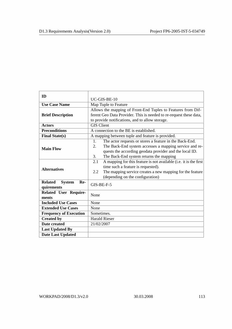
D1.3 Requirements Analysis(Version 2.0) Project FP6-2005-IST-5-034749
IDUC-GIS-BE-10
Use Case Name Map Tuple to Feature
Brief DescriptionAllows the mapping of Front-End Tuples to Features from Dif-ferent Geo Data Provider. This is needed to re-request these data,to provide notifications, and to allow storage.
Actors GIS ClientPreconditions A connection to the BE is established.Final State(s) A mapping between tuple and feature is provided.
Main Flow
1. The actor requests or stores a feature in the Back-End.2. The Back-End system accesses a mapping service and re-
quests the according geodata provider and the local ID.3. The Back-End system returns the mapping
Alternatives
2.1 A mapping for this feature is not available (i.e. it is the firsttime such a feature is requested).
2.2 The mapping service creates a new mapping for the feature(depending on the configuration)
Related System Re-quirements
GIS-BE-F-5
Related User Require-ments
None
Included Use Cases NoneExtended Use Cases NoneFrequency of Execution Sometimes.Created by Harald RieserDate created 21/02/2007Last Updated ByDate Last Updated
WORKPAD/2008/D1.3/v2.0 30.03.2008 113

4. USE CASE DESCRIPTIONS
IDUC-GIS-BE-11
Use Case Name Create Feature QueryBrief Description Creates a Feature Query from a Tuple request.Actors GIS ClientPreconditions A connection to the BE is established.Final State(s) A request to the geo datasource is provided.
Main Flow1. The actor requests or stores a feature in the Back-End.2. The Back-End system creates feature query for the feature.3. The Back-End system returns the query
Alternatives None.Related System Re-quirements
None
Related User Require-ments
None
Included Use Cases NoneExtended Use Cases NoneFrequency of Execution Sometimes.Created by Harald RieserDate created 21/02/2007Last Updated ByDate Last Updated
IDUC-GIS-BE-12
Use Case Name Create Map QueryBrief Description Creates a Map Query from a Tuple request.Actors GIS ClientPreconditions A connection to the BE is established.Final State(s) A request to the geo datasource is provided.
Main Flow1. The actor requests or stores a feature in the Back-End.2. The Back-End system creates feature query for the map.3. The Back-End system returns the query
Alternatives None.Related System Re-quirements
None
Related User Require-ments
None
Included Use Cases NoneExtended Use Cases NoneFrequency of Execution Sometimes.Created by Harald RieserDate created 21/02/2007Last Updated ByDate Last Updated
114 30.03.2008 WORKPAD/2008/D1.3/v2.0

D1.3 Requirements Analysis(Version 2.0) Project FP6-2005-IST-5-034749
IDUC-GIS-BE-13
Use Case Name Execute Map QueryBrief Description Executes a Map Request to the geo datasource.Actors GIS ClientPreconditions A connection to the BE is established.Final State(s) A list of features conforming to the query are returned.
Main Flow
1. The actor requests a map from the Back-End.2. The Back-End system executes the map-query on the geo
datasource.3. The geo datasource creates the map.4. The geo datasource the map to the Back-End system.3. The Back End system creates the map-tuple for the client.
Alternatives None.Related System Re-quirements
None
Related User Require-ments
None
Included Use Cases NoneExtended Use Cases NoneFrequency of Execution Sometimes.Created by Harald RieserDate created 21/02/2007Last Updated ByDate Last Updated
WORKPAD/2008/D1.3/v2.0 30.03.2008 115

4. USE CASE DESCRIPTIONS
4.8.2 P2P Data Integration System - Relevant Use Cases forthe GIS Back-End
The description of the P2P Data Integration System use casesrelevant for theGIS Back-End can be found in the section 4.9 (’Performing Query’, ’DefiningLocal Mappings’).
4.9 Peer-to-Peer Data Integration System
The Peer-to-Peer Data Integration System represents the WORKPAD’s Back-end designed as a peer-to-peer network provided with a Web Services platformwhich allows data exchange and integration. By plugging in the WORKPAD’sBack-end network, a back-office system qualifies a WORKPAD Back-endpeer. A peer is an information system which can act as data provider, con-sumer and integrator.Each peer exports its ontology, allows a rapid integration of a variety of datasources, both internal and external, by means of mappings from availablesources to the ontology. By mapping their ontologies the one into other, peersystems will achieve semantic integration without resorting on global ontolo-gies.The P2P Back-end system implements two kind of use cases:
UC-GIS-BE-6UC-GIS-BE-7UC-GIS-BE-8UC-GIS-BE-9UC-GIS-BE-10UC-GIS-BE-11UC-GIS-BE-12UC-GIS-BE-13• Modeling Use Cases• Knowledge related Peer Use Cases
The ’Modeling Use Cases’ describe user interactions for defining the peer’sontology and mappings toward local source and other Peer’s ontologies. The’Knowledge Peer related Use Cases’ describe interactions from Front-End de-vices and Back-end external systems for performing queries and managingnotifications.A peer is capable of answering conjunctive queries expressed in the alphabetof ontology terms and may also receive and forward notifications of relevantupdates that occur by other systems in the network.
116 30.03.2008 WORKPAD/2008/D1.3/v2.0

D1.3 Requirements Analysis(Version 2.0) Project FP6-2005-IST-5-034749
Figure 4.9: Use Cases of the Peer-to-Peer Data Integration System
WORKPAD/2008/D1.3/v2.0 30.03.2008 117

4. USE CASE DESCRIPTIONS
ID UC-DI-1Use Case Name Importing OntologyBrief Description Imports an ontology into the Knowledge Peer.Actors Knowledge EngineerPreconditions None.Final State(s) The Peer’s local ontology is set.
Main Flow
1. The actor imports the ontology trough the Peer’s dedicatedservice.
2. The System translates the ontology according to the inter-nal model and checks if that model is consistent.
3. The System sets the new ontology as local ontology.Alternatives None.Related System Re-quirements
DI-PTS-1, DI-U-2, DI-U-4, G-13
Related User Require-ments
B-16, C-1, G-5, G-27, G-32
Included Use Cases None.Extended Use Cases None.Frequency of Execution Sometimes.Created by Alessandro Faraotti, Berardino SalvatoreDate created 13/12/2007Last Updated ByDate Last Updated
118 30.03.2008 WORKPAD/2008/D1.3/v2.0

D1.3 Requirements Analysis(Version 2.0) Project FP6-2005-IST-5-034749
IDUC-DI-2
Use Case Name Defining OntologyBrief Description Definition of the intensional knowledge for a peer.Actors Knowledge EngineerPreconditions None.Final State(s) An ontology is defined and ready to be loaded on a peer.
Main Flow
1. The actor designs the ontology’s intensional layer as anUML Class Diagram using a Rich Client Platform.
2. The System validates the diagram according the DL in use.3. The model is saved and exported by the Knowledge Engi-
neer.Alternatives None.Related System Re-quirements
DI-PTS-1, DI-U-1, DI-U-2, DI-U-4, G-4, G-13
Related User Require-ments
B-16, B-17, C-1, G-5, G-27, G-32
Included Use Cases None.Extended Use Cases None.Frequency of Execution Sometimes.Created by Alessandro Faraotti, Berardino SalvatoreDate created 13/12/2007Last Updated ByDate Last Updated
WORKPAD/2008/D1.3/v2.0 30.03.2008 119
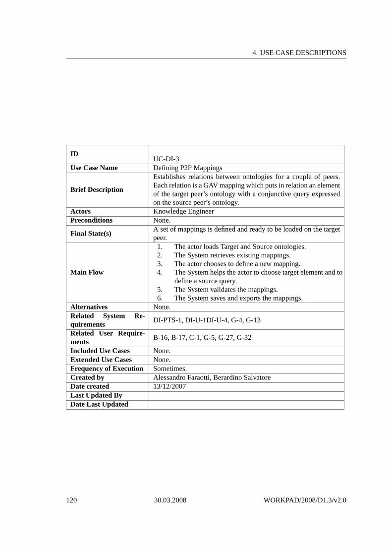
4. USE CASE DESCRIPTIONS
IDUC-DI-3
Use Case Name Defining P2P Mappings
Brief Description
Establishes relations between ontologies for a couple of peers.Each relation is a GAV mapping which puts in relation an elementof the target peer’s ontology with a conjunctive query expressedon the source peer’s ontology.
Actors Knowledge EngineerPreconditions None.
Final State(s)A set of mappings is defined and ready to be loaded on the targetpeer.
Main Flow
1. The actor loads Target and Source ontologies.2. The System retrieves existing mappings.3. The actor chooses to define a new mapping.4. The System helps the actor to choose target element and to
define a source query.5. The System validates the mappings.6. The System saves and exports the mappings.
Alternatives None.Related System Re-quirements
DI-PTS-1, DI-U-1DI-U-4, G-4, G-13
Related User Require-ments
B-16, B-17, C-1, G-5, G-27, G-32
Included Use Cases None.Extended Use Cases None.Frequency of Execution Sometimes.Created by Alessandro Faraotti, Berardino SalvatoreDate created 13/12/2007Last Updated ByDate Last Updated
120 30.03.2008 WORKPAD/2008/D1.3/v2.0

D1.3 Requirements Analysis(Version 2.0) Project FP6-2005-IST-5-034749
IDUC-DI-4
Use Case Name Import Mappings
Brief DescriptionImports local and P2P mappings. Local mappings are betweenPeer’s local ontology and sources. P2P mappings are beetwenPeer’s local ontology and other Peers’ ontologies.
Actors Knowledge Engineer, Database EngineerPreconditions Local ontology and sources are already imported.Final State(s) Mappings are loaded into the Peer.
Main Flow
1. The actor loads mappings on the Peer through the dedi-cated service.
2. The System validate each mapping.3. The System stores the mappings.
Alternatives None.Related System Re-quirements
DI-PTS-1, DI-U-4, G-13
Related User Require-ments
B-16, C-1, G-5, G-27, G-32
Included Use Cases None.Extended Use Cases None.Frequency of Execution Sometimes.Created by Alessandro Faraotti, Berardino SalvatoreDate created 13/12/2007Last Updated ByDate Last Updated
WORKPAD/2008/D1.3/v2.0 30.03.2008 121

4. USE CASE DESCRIPTIONS
IDUC-DI-5
Use Case Name Defining Local Mappings
Brief Description
Establishes relations between peer’s ontology and sources. Eachrelation is a GAV mapping which puts in relation an element ofthe target peer’s ontology with a conjunctive query expressed onthe source virtual relations.
Actors Knowledge Engineer, Database EngineerPreconditions None.
Final State(s)A set of local mappings is defined and ready to be loaded on thetarget peer.
Main Flow
1. The actor loads the local ontology.2. The actor chooses a source.3. The System retrieves existing mappings between local on-
tology and the selected source’s relations.4. The actor chooses to define a new mapping.5. The System helps the actor to choose a target element and
to define a source query.6. The System validates the mappings.7. The Systems saves and exports the mappings.
Alternatives None.Related System Re-quirements
DI-PTS-1, DI-U-1, DI-U-4, G-4, G-13
Related User Require-ments
B-16, B-17, C-1, G-5, G-8, G-27, G-32
Included Use Cases None.Extended Use Cases None.Frequency of Execution Sometimes.Created by Alessandro Faraotti, Berardino SalvatoreDate created 13/12/2007Last Updated ByDate Last Updated
122 30.03.2008 WORKPAD/2008/D1.3/v2.0

D1.3 Requirements Analysis(Version 2.0) Project FP6-2005-IST-5-034749
IDUC-DI-6
Use Case Name Defining Sources
Brief DescriptionDefinition of a set of sources for a peer. To define each source theDatabase Engineer has to specify how to access it and to definevirtual relations exported by the source.
Actors Database EngineerPreconditions None.Final State(s) A set of source is defined and ready to be loaded on a Peer.
Main Flow
1. The actor wants to add a new source.2. The actor provides source location informations (URL).3. The actor provides credentials for the interested peer.4. The System validates connection and access rights.5. The actpr explores the source’s schema and define virtual
relations; for each virtual relation he specify the query tobe performed on the source in order to fill it.
6. The System validates each virtual relation.7. The System saves and exports all the information about the
sources.Alternatives None.Related System Re-quirements
DI-PTS-1, DI-U-1, DI-U-3, DI-U-4, G-13, DI-F-1, B-5
Related User Require-ments
B-16, C-1, G-5, G-8, G-27, G-32
Included Use Cases None.Extended Use Cases None.Frequency of Execution Sometimes.Created by Alessandro Faraotti, Berardino SalvatoreDate created 13/12/2007Last Updated ByDate Last Updated
WORKPAD/2008/D1.3/v2.0 30.03.2008 123
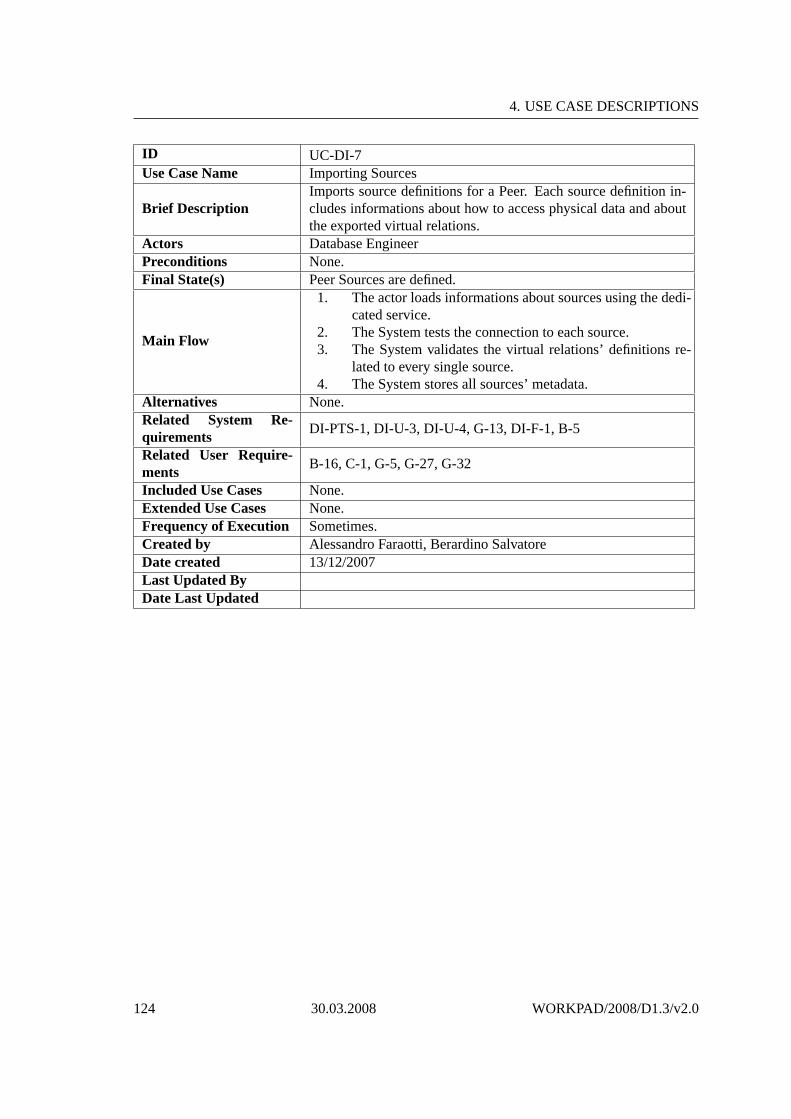
4. USE CASE DESCRIPTIONS
ID UC-DI-7Use Case Name Importing Sources
Brief DescriptionImports source definitions for a Peer. Each source definition in-cludes informations about how to access physical data and aboutthe exported virtual relations.
Actors Database EngineerPreconditions None.Final State(s) Peer Sources are defined.
Main Flow
1. The actor loads informations about sources using the dedi-cated service.
2. The System tests the connection to each source.3. The System validates the virtual relations’ definitions re-
lated to every single source.4. The System stores all sources’ metadata.
Alternatives None.Related System Re-quirements
DI-PTS-1, DI-U-3, DI-U-4, G-13, DI-F-1, B-5
Related User Require-ments
B-16, C-1, G-5, G-27, G-32
Included Use Cases None.Extended Use Cases None.Frequency of Execution Sometimes.Created by Alessandro Faraotti, Berardino SalvatoreDate created 13/12/2007Last Updated ByDate Last Updated
124 30.03.2008 WORKPAD/2008/D1.3/v2.0

D1.3 Requirements Analysis(Version 2.0) Project FP6-2005-IST-5-034749
IDUC-DI-8
Use Case Name Performing Query
Brief DescriptionPerforms a Conjunctive Query over the Peer-to-Peer Data In-tegtration System.
Actors Team MemberPreconditions Ontology, sources and mappings are already been defined.Final State(s) None.
Main Flow
1. The actor performs a Conjunctive Query using the dedi-cated service.
2. The System expands the query using the Reasoner.3. Expanded queries are unfolded over local sources and over
foreign ontologies.4. Local queries are executed over sources.5. P2P queries are performed over other peers.6. The System merges and returns the results.
Alternatives None.Related System Re-quirements
DI-F-1, DI-F-2, DI-F-3, DI-F-4, DI-PTS-2, DI-PTS-4, DI-PTS-5,DI-PTS-6, DI-PTS-7, DI-PTS-8,DI-D-1
Related User Require-ments
B-1, B-2, B-4, B-5, B-12, G-3, G-5, G-12, G-20, G-36, F-6
Included Use Cases None.Extended Use Cases None.Frequency of Execution Very often.Created by Alessandro Faraotti, Berardino SalvatoreDate created 13/12/2007Last Updated ByDate Last Updated
WORKPAD/2008/D1.3/v2.0 30.03.2008 125

4. USE CASE DESCRIPTIONS
IDUC-DI-9
Use Case Name Sub-Unsubscribing Query
Brief DescriptionManifests interest for information updates concerning a certainConjunctive Query.
Actors Team MemberPreconditions Ontology, source and mappings were already been defined.Final State(s) A subscription to a query is added or removed.
Main Flow
1. The actor uses subscribe service to add a subscription to aquery.
2. The System retrieves interested virtual relations and relatedinvolved physical data sources.
3. The System saves metadata and waits for data updates no-tifications.
Alternatives None.Related System Re-quirements
DI-F-5, DI-PTS-6, DI-PTS-8, DI-D-2
Related User Require-ments
B-12, B-13, G-12, G-20
Included Use Cases None.Extended Use Cases None.Frequency of Execution Often.Created by Alessandro Faraotti, Berardino SalvatoreDate created 13/12/2007Last Updated ByDate Last Updated
126 30.03.2008 WORKPAD/2008/D1.3/v2.0

D1.3 Requirements Analysis(Version 2.0) Project FP6-2005-IST-5-034749
IDUC-DI-10
Use Case Name Notifying UpdateBrief Description An External Process notify a source’s update to the system.Actors Team MemberPreconditions None.Final State(s) None.
Main Flow
1. The actor notifies a change in a source through the dedi-cated service.
2. The System retrieves the involved queries and the associ-ated client URIs.
3. The System creates a Pending Notification for each in-volved client.
4. Pending Notification are stored into the repository.Alternatives None.Related System Re-quirements
DI-F-5, DI-PTS-6, DI-D-2
Related User Require-ments
F-7, B-12, B-13, G-12
Included Use Cases None.Extended Use Cases UC-DI-10Frequency of Execution Very often.Created by Alessandro Faraotti, Berardino SalvatoreDate created 13/12/2007Last Updated ByDate Last Updated
WORKPAD/2008/D1.3/v2.0 30.03.2008 127

4. USE CASE DESCRIPTIONS
IDUC-DI-11
Use Case Name Notifying Subscriber
Brief DescriptionNotification about data changes are sent to subscribers when theTimer expires.
Actors Team MemberPreconditions There is a pending notification.Final State(s) The pending notification is removed.
Main Flow
1. The Timer is expired.2. The System extracts a Pending Notifications from the
repository.3. The System sends a notification to the appropriate user
through its Notification Endpoint.Alternatives None.Related System Re-quirements
DI-F-5, DI-PTS-6, DI-D-1, DI-D-2
Related User Require-ments
B-11, B-12, B-13, F-7, G-12,
Included Use Cases None.Extended Use Cases None.Frequency of Execution Very often.Created by Alessandro Faraotti, Berardino SalvatoreDate created 13/12/2007Last Updated ByDate Last Updated
128 30.03.2008 WORKPAD/2008/D1.3/v2.0

Chapter 5
Requirements
This section gives details about the requirements analysedin work-packageone and embodies the results of the second iteration in the RE process. Thesection is subdivided into three further parts:(i) the user requirements (Sec-tion 5.1),(ii) the system requirements (Section 5.2), and some relevant perfor-mance measure considerations (Section 5.3).
5.1 User Requirements
All of the user requirements listed in the following Sections 5.1.1, 5.1.2, 5.1.3,and 5.1.4 have been slightly reformulated–with respect to the first version ofDeliverable D1.3v1–to make the emphasis on theuserclearer. Some require-ments are due to the progress of the project considered as invalid accordingto newer insights. D1.3v1 collected requirements without separating betweenuser and system requirements. This separation is now conducted in D1.3v2.The user requirements listed here are mainly coming from theD1.3v1 doc-ument. The wording, however, was changed in order to reflect the fact thatwe want to make the separation between user and system requirements clear.Thus, most of the requirements of D1.3v1 were modified and notentirely re-cited. We short-list the user requirements in this section and for the details wereferred back to version 1. All the IDs remained the same in order to guaran-tee back-traceability. Significant changes are documentedand justified in thissection.In addition to the user requirements stemming from the D1.3v1, new user re-quirements could be gathered from the first user evaluation of the WORKPADcomponent prototypes based on online accessible mock-up presentations anda questionnaire. These new requirements are also listed subsequently. Detailsabout this user evaluation are described in the later deliverable D6.1.The user requirements are classified according to the categories: General (G),Communication (C), Back-end (B), and Front-end (F). In addition, a relationof each user requirement to one or more use cases is indicated. Whenever a
129

5. REQUIREMENTS
requirement has been modified regarding the initial specification, this is indi-cated by CHANGED or INVALID and the rationale is provided.
5.1.1 General User Requirements (G)
UC-DI-1UC-DI-2UC-DI-3UC-DI-4UC-DI-5UC-DI-6UC-DI-7UC-DI-8UC-DI-9UC-DI-10UC-DI-11G-1 INVALID : The user must be able to deploy WORKPAD services alsowhen the scale of a disaster goes across national bordersRationale:After careful analyses, we found a lot of issues (e.g., multilingualismor different political systems) whose solution is out of thescope of theproject WORKPAD. Hence, this requirement defined in D1.3v1 iscon-sidered as invalid.
G-2 INVALID : The user must be able to deploy WORKPAD services or in-formation resources at different levels (from local to EU level) and alsoacross borders.Rationale:This requirement defined in D1.3v1 is considered as invalid as a lot ofopen issues are out of the scope of the project WORKPAD.
G-3 The user must be able to access spatial as well as non-spatial informationthrough one platform.Related Use Cases:UC-GIS-BE-1, UC-DI-8
G-4 CHANGED: The WORKPAD system must ensure technical and semanticinteroperability.Rationale:This requirement defined in D1.3v1 is a system requirement and hencemoved to the corresponding Section 5.2.12 requirement G-4.
G-5 The user should be able to connect via the WORKPAD system totheEuropean Monitoring and Information Center.Related Use Cases:UC-DI-1, UC-DI-2, UC-DI-3, UC-DI-4, UC-DI-5, UC-DI-6, UC-DI-7
G-6 INVALID : The WORKPAD system should provide different levels of se-curity.Rationale:This requirement defined in D1.3v1 is considered as invalid as it is out ofthe scope of the project WORKPAD.
G-7 INVALID : For the user, bureaucracy should be decreased as much as pos-sible by using the WORKPAD system.Rationale:This requirement defined in D1.3v1 is considered as invalid as it is refinedin user requirement B-4 and system requirement DI-F-1.
G-8 The user must be sure that data confidentially of involvedorganizationsis taken into account.
130 30.03.2008 WORKPAD/2008/D1.3/v2.0

D1.3 Requirements Analysis(Version 2.0) Project FP6-2005-IST-5-034749
Related Use Cases:This requirement is not unambiguously relatable to use cases. Exampleswould be UC-DI-5, or UC-DI-6.
G-9 INVALID : The WORKPAD system must be built up upon standardizedtechnology.Rationale:This requirement defined in D1.3v1 is considered as invalid as it is toovague and cannot be measured accordingly. It is nevertheless one of thedesign goals of WORKPAD to emphasis on the deployment of open stan-dards (See Deliverables D2.1, D3.1, and D4.1 that describe adopted con-cepts and technologies).
G-10 INVALID : The WORKPAD system must use open architectures.Rationale:This requirement defined in D1.3v1 is considered as invalid.Reason isthe same as for requirement G-9.
G-11 The user must be able to exploit the WORKPAD system in all kinds ofdisasters (natural, technical and man-made).Related Use Cases:This requirement is not unambiguously relatable to use cases. It is anorthogonal non-functional requirement and hence, relevant for many usecases and system components.
G-12 The user must be able to access relevant data-sources ofdifferent organi-zations involved in the emergency management process through WORK-PAD.Related Use Cases:UC-DI-8, UC-DI-9, UC-DI-10
G-13 CHANGED: The WORKPAD components referring to geo-data shouldcomply to European initiatives like INSPIRE and GMES.Rationale:This requirement defined in D1.3v1 is a system requirement and hencemoved to the corresponding Section 5.2.12 requirement G-13.
G-14 The way the users interact with the WORKPAD system with respect tothe user interface should be exchangeable.Related Use Cases:This requirement is not unambiguously relatable to use cases. It is anorthogonal non-functional requirement and hence, relevant for many usecases and system components.
G-15 The user must be able to install new WORKPAD nodes (eitherFE or BE)within 4 hours.Related Use Cases:UC-MANET-3
G-16 By using the WORKPAD system, the user shall be able to improve theeffectiveness in her emergency management processes by 5 – 50%.Related Use Cases:
WORKPAD/2008/D1.3/v2.0 30.03.2008 131
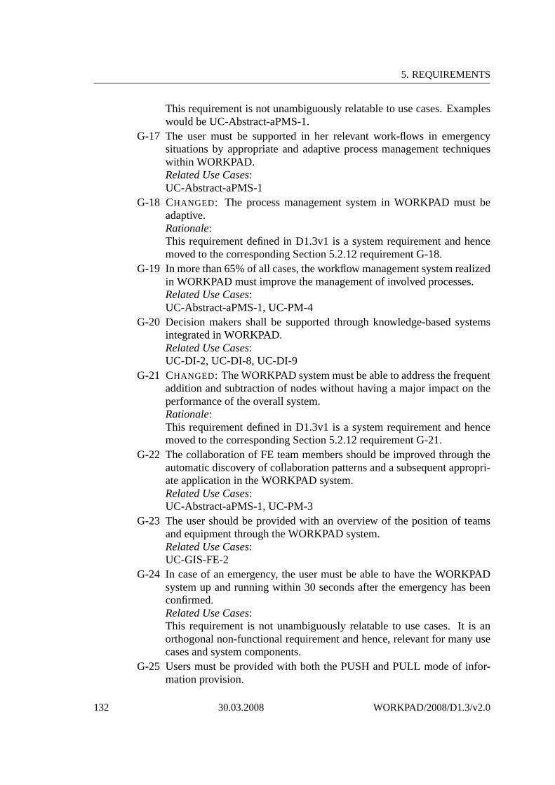
5. REQUIREMENTS
This requirement is not unambiguously relatable to use cases. Exampleswould be UC-Abstract-aPMS-1.
G-17 The user must be supported in her relevant work-flows in emergencysituations by appropriate and adaptive process managementtechniqueswithin WORKPAD.Related Use Cases:UC-Abstract-aPMS-1
G-18 CHANGED: The process management system in WORKPAD must beadaptive.Rationale:This requirement defined in D1.3v1 is a system requirement and hencemoved to the corresponding Section 5.2.12 requirement G-18.
G-19 In more than 65% of all cases, the workflow management system realizedin WORKPAD must improve the management of involved processes.Related Use Cases:UC-Abstract-aPMS-1, UC-PM-4
G-20 Decision makers shall be supported through knowledge-based systemsintegrated in WORKPAD.Related Use Cases:UC-DI-2, UC-DI-8, UC-DI-9
G-21 CHANGED: The WORKPAD system must be able to address the frequentaddition and subtraction of nodes without having a major impact on theperformance of the overall system.Rationale:This requirement defined in D1.3v1 is a system requirement and hencemoved to the corresponding Section 5.2.12 requirement G-21.
G-22 The collaboration of FE team members should be improvedthrough theautomatic discovery of collaboration patterns and a subsequent appropri-ate application in the WORKPAD system.Related Use Cases:UC-Abstract-aPMS-1, UC-PM-3
G-23 The user should be provided with an overview of the position of teamsand equipment through the WORKPAD system.Related Use Cases:UC-GIS-FE-2
G-24 In case of an emergency, the user must be able to have the WORKPADsystem up and running within 30 seconds after the emergency has beenconfirmed.Related Use Cases:This requirement is not unambiguously relatable to use cases. It is anorthogonal non-functional requirement and hence, relevant for many usecases and system components.
G-25 Users must be provided with both the PUSH and PULL mode ofinfor-mation provision.
132 30.03.2008 WORKPAD/2008/D1.3/v2.0

D1.3 Requirements Analysis(Version 2.0) Project FP6-2005-IST-5-034749
Related Use Cases:This requirement is not unambiguously relatable to use cases. Exampleswould be UC-GIS-FE-1, or UC-GIS-FE-2.
G-26 The user must be able to query user-specific and context-sensitive infor-mation from the WORKPAD system.Related Use Cases:UC-GIS-FE-10
G-27 Also users from external organizations (such as voluntary organizations)must be integrable into the WORKPAD system.Related Use Cases:UC-DI-1, UC-DI-2, UC-DI-3, UC-DI-4, UC-DI-5, UC-DI-6, UC-DI-7
G-28 The users shall be assisted in collective decision making processes byWORKPAD.Related Use Cases:UC-WLH-1, UC-WLH-2, UC-WLH-3
G-29 Usability issues shall be taken into account.Related Use Cases:This requirement is not unambiguously relatable to use cases. It is anorthogonal non-functional requirement and hence, relevant for many usecases and system components.
G-30 INVALID : Human-to-human interaction such as voice and data commu-nication shall be enabled in WORKPAD.Rationale:This requirement defined in D1.3v1 is considered as invalid as it is refinedin user requirement F-21 F-22.
G-31 The user shall be able to get (quasi) real-time and comprehensive infor-mation about the current status of the situation.Related Use Cases:UC-Abstract-aPMS-1, UC-Abstract-aPMS-2, UC-GIS-FE-2, UC-DI-11
G-32 By WORKPAD, the user should have the possibility to exploit variousintegrated, EU related initiatives in order to make use of the expertiseavailable.Related Use Cases:This requirement is not unambiguously relatable to use cases. Exampleswould be UC-DI-1, UC-DI-2, UC-DI-3, UC-DI-4, UC-DI-5, UC-DI-6,or UC-DI-7.
G-33 The user shall be confronted with a user interface as simple as possiblewhere the number of clicks to reach a certain goal is reduced to a mini-mum.Related Use Cases:This requirement is not unambiguously relatable to use cases. It is anorthogonal non-functional requirement and hence, relevant for many usecases and system components.
WORKPAD/2008/D1.3/v2.0 30.03.2008 133

5. REQUIREMENTS
G-34 The user should be able to get simple assistance such as ahelp guide ortool-tips.Related Use Cases:This requirement is not unambiguously relatable to use cases. It is anorthogonal non-functional requirement and hence, relevant for many usecases and system components.
G-35 The user must be notified about events (such as incoming messages, newtasks etc.) in an appropriate way (sound, vibration etc.).Related Use Cases:This requirement is not unambiguously relatable to use cases. It is anorthogonal non-functional requirement and hence, relevant for many usecases and system components.
G-36 The user should be able to query additional, external data such as, e.g.,weather forecasts.Related Use Cases:This requirement is not unambiguously relatable to use cases. Exampleswould be UC-DI-8.
G-37 The user shall be supported in her coordination activities by geographicdata.Related Use Cases:UC-GIS-FE-1, UC-GIS-FE-2, UC-GIS-FE-3
5.1.2 Communication (C)
C-1 By using WORKPAD, the user must be able to be connected betweendifferent organizations involved in an emergency.Related Use Cases:UC-DI-1, UC-DI-2, UC-DI-3, UC-DI-4, UC-DI-5, UC-DI-6, or UC-DI-7
C-2 The user must be able to transfer operational data also over low bandwidthnetworks.Related Use Cases:UC-MANET-1, UC-MANET-2
C-3 CHANGED: The WORKPAD system must have a self-organizing andself-healing network.Rationale:This requirement defined in D1.3v1 is a system requirement and hencemoved to the corresponding Section 5.2.12 requirement C-3.
C-4 The user’s communication must be guaranteed via fault-tolerant networkservices.Related Use Cases:UC-MANET-1, UC-MANET-2
C-5 CHANGED: The service quality of the network must be approximatelyequal when serving a range of 5 to 50 peers at the BE and 5 to 100 peers
134 30.03.2008 WORKPAD/2008/D1.3/v2.0

D1.3 Requirements Analysis(Version 2.0) Project FP6-2005-IST-5-034749
at the FE.Rationale:This requirement defined in D1.3v1 is a system requirement and hencemoved to the corresponding Section 5.2.12 requirement C-5.
C-6 The user must not notice dynamic joins or leaves of networknodes; in-stead the network must be able to (re-)configure itself.Related Use Cases:UC-MANET-1, UC-MANET-2
C-7 INVALID : The user must be provided with network security and trustmechanisms.Rationale:This requirement defined in D1.3v1 is considered as invalid as it is out ofthe scope of the project WORKPAD.
C-8 The user must have a network availability rate of more that90%.Related Use Cases:UC-MANET-1, UC-MANET-2
C-9 FE team members shall exhibit a rate of message loss less than 30% intheir MANET.Related Use Cases:UC-MANET-1, UC-MANET-2
C-10 When connecting from the FE to the BE, the user shall not encounter arate of message loss greater than 30%.Related Use Cases:UC-MANET-1, UC-MANET-2
C-11 CHANGED: Data loss through uneven network load shall be avoided.Rationale:This requirement defined in D1.3v1 is a system requirement and hencemoved to the corresponding Section 5.2.12 requirement C-11.
C-12 The user shall be able to configure the network concerningthe FE andFE/BE link regarding (dynamic, adaptive, and time-varying)QoS in orderto define different priorities for different types of traffic.Related Use Cases:UC-MANET-3
5.1.3 Back-End (B)
B-1 The users of the regional Civil Protection Department and of the organi-zations involved in an emergency must be able to request datastored inthe BE.Related Use Cases:UC-DI-8
B-2 Authorized users must be able to query diverse relevant information frominvolved organizations or institutions.
WORKPAD/2008/D1.3/v2.0 30.03.2008 135

5. REQUIREMENTS
Related Use Cases:UC-DI-8
B-3 INVALID : The BE must provide the possibility (to other WORKPAD en-tities) to access, modify and store data kept in the BE infrastructure.Rationale:This requirement defined in D1.3v1 is considered as invalid.The BE is anintegrated knowledge base that can be queried. Data cannot be stored tothe BE peers per se. This would violate the BE peer owner’s privacy andintegrity. It is, however, possible that organisations internally can accesstheir BE counterpart in to write data (c.f., the GIS-BE).
B-4 The user must be able to access various data sources integrated in the BEthrough a well-known interface.Related Use Cases:UC-DI-8
B-5 CHANGED: The user shall be able to exploit semantic query mechanisms.
Rationale:This requirement defined in D1.3v1 has been slightly improved regardingphrasing.Related Use Cases:UC-DI-8
B-6 CHANGED: In order to provide the required flexibility, the BE shall useaP2P-based integration of various data sources.Rationale:This requirement defined in D1.3v1 is a system requirement and hencemoved to the corresponding Section 5.2.12 requirement B-5.
B-7 INVALID : The BE must provide the infrastructure for applications to col-lect relevant data in order to model and support complex workflows.Rationale:This requirement defined in D1.3v1 is considered as invalid.The work-flow engine and related modeling tasks are entirely encapsulated withinthe FE. The BE can only support by providing relevant data.
B-8 CHANGED: The grid-based query engine of the BE must be scalable.Rationale:This requirement defined in D1.3v1 is a system requirement and hencemoved to the corresponding Section 5.2.12. It is transformed into thesystem requirement DI-PTS-3.
B-9 CHANGED: The query engine in the BE must realize an improvement of5 – 50 % (depending on the specific queries) over a similar traditionalsystem not optimized for emergency (i.e., real time) scenarios.Rationale:This requirement defined in D1.3v1 is a system requirement and hencemoved to the corresponding Section 5.2.12. It is transformed into thesystem requirement DI-PTS-4.
136 30.03.2008 WORKPAD/2008/D1.3/v2.0

D1.3 Requirements Analysis(Version 2.0) Project FP6-2005-IST-5-034749
B-10 CHANGED: The BE must enable the integration and exchange of infor-mation provided in variety of formats and belonging to different organi-zations.Rationale:This requirement defined in D1.3v1 is a system requirement and hencemoved to the corresponding Section 5.2.12. It is transformed into thesystem requirement DI-F-1.
B-11 Users must be able to get notifications about (generic) information up-dates at the inter-organizational level related to subscriptions.Related Use Cases:UC-DI-11
B-12 The user (e.g., a FE team member) must be supported in her coordinativeactivities through integrated information coming from BE sources.Related Use Cases:UC-DI-8, UC-DI-9, UC-DI-11
B-13 CHANGED: The user (e.g., FE team leader) must be able to (re)distributetasks according to a given process and according to given situations, whenrelevant events in the BE fire resulting in a change of state of knowledge.
Rationale:This requirement defined in D1.3v1 has been slightly improved regardingphrasing.Related Use Cases:UC-DI-9, UC-DI-11
B-14 CHANGED: The user must be able to query geographic data from the BE.
Rationale:This requirement defined in D1.3v1 has been slightly improved regardingphrasing.Related Use Cases:UC-GIS-BE-10
B-15 INVALID : Users should be provided with a security mechanisms withrespect to data access.Rationale:This requirement defined in D1.3v1 is considered as invalid as it is refinedin user requirement G-8.
B-16 The user should be provided with one single administration tool to man-age all the functionality of the BE.Related Use Cases:UC-DI-1, UC-DI-2, UC-DI-3, UC-DI-4, UC-DI-5, UC-DI-6, UC-DI-7
B-17 CHANGED: The user must be able to define ontologies for the informa-tion provided by her system and define mappings to other ontologies.Rationale:This is a new requirement which did not exist in D1.3v1. The source
WORKPAD/2008/D1.3/v2.0 30.03.2008 137

5. REQUIREMENTS
of the requirement is the mock-up based online usability evaluation byusers.Related Use Cases:UC-DI-2, UC-DI-3, UC-DI-5,
5.1.4 Front-End (F)
F-1 The users in FE teams must be able to electronically communicate withthe BE and request data.Related Use Cases:UC-MANET-1, UC-MANET-2
F-2 The users in FE teams must be able to deliver information to the BE.Related Use Cases:UC-GIS-FE-10,
F-3 The configurations of FE teams must be supported by appropriate com-munication means (here: establishment of mobile ad hoc networks(MANETs)).Related Use Cases:UC-MANET-3
F-4 FE users must be connected through communication paths among them-selves within the team and must additionally be connected tothe BE.Related Use Cases:UC-MANET-3
F-5 CHANGED: FE entities must be connected through communication pathswith other mobile teams for network redundancy reasons.Rationale:This requirement defined in D1.3v1 is a system requirement and hencemoved to the corresponding Section 5.2.12 requirement F-4.
F-6 The user must be able to retrieve data from the BE, to insertnew data atthe FE, and to transfer and store the data at the BE.Related Use Cases:UC-GIS-BE-1, UC-DI-8
F-7 The user must be supported by notification mechanisms.Related Use Cases:UC-aPMS-3, UC-aPMS-4, UC-DI-11
F-8 INVALID : The users in FE teams must be supported through a flexible andadaptive workflow management system which provides context-sensitiveinformation.Rationale:This requirement defined in D1.3v1 is considered as invalid as it is out ofthe scope of the project WORKPAD.
F-9 Information must be presented to the user in an appropriate, user-friendly(i.e. usable) way.
138 30.03.2008 WORKPAD/2008/D1.3/v2.0

D1.3 Requirements Analysis(Version 2.0) Project FP6-2005-IST-5-034749
Related Use Cases:This requirement is not unambiguously relatable to use cases. It is anorthogonal non-functional requirement and hence, relevant for many usecases and system components.
F-10 The user must be supported by applications including basic GIS function-alities.Related Use Cases:UC-GIS-FE-1, UC-LS-2, UC-MME-5
F-11 The user should be able to use the WORKPAD system not only on onehardware platform.Related Use Cases:This requirement is not unambiguously relatable to use cases. It is anorthogonal non-functional requirement and hence, relevant for many usecases and system components.
F-12 The user must be able to use FE devices and software as data input andoutput devices, necessarily also interacting with the BE.Related Use Cases:This requirement is not unambiguously relatable to use cases. Exampleswould be UC-GIS-FE-3. Basically, this requirement is valid for all FEcomponents providing a GUI as interface to the user.
F-13 Users in FE teams or entities shall be localizable.Related Use Cases:UC-CMMF-1, UC-CMMF-4
F-14 INVALID : The users in FE teams should be supported through navigationfunctionalities.Rationale:This requirement defined in D1.3v1 is considered as invalid as it is refinedin user requirement F-27.
F-15 INVALID : Redundant network paths must be provided especially at theFE in order to avoid possible disconnections.Rationale:This requirement defined in D1.3v1 is considered as invalid as it is refinedin user requirement F-4.
F-16 INVALID : The WORKPAD components should be energy efficient.Rationale:This requirement defined in D1.3v1 is considered as invalid.It has beendecided that this issue is out of scope of the project WORKPAD.
F-17 The user shall be able to install and exploit WORKPAD FE applicationson robust hardware.Related Use Cases:This requirement is not unambiguously relatable to use cases. It is anorthogonal non-functional requirement and hence, relevant for many usecases and system components.
WORKPAD/2008/D1.3/v2.0 30.03.2008 139

5. REQUIREMENTS
F-18 The user must be able to use WORKPAD applications also in astandalonemode.Related Use Cases:This requirement is not unambiguously relatable to use cases. It is anorthogonal non-functional requirement and hence, relevant for many usecases and system components.
F-19 In order to increase usability, one single tool should be provided to theuser for all necessary tasks.Related Use Cases:This requirement is not unambiguously relatable to use cases. It is anorthogonal non-functional requirement and hence, relevant for many usecases and system components.
F-20 The users of FE teams should be supported by the WORKPAD system incollaboration, data exchange, and the exploitation of distributed servicesand information when operating in the field.Related Use Cases:UC-LS-2, UC-Abstract-aPMS-1, UC-Abstract-aPMS-2, UC-GIS-FE-2,UC-GIS-FE-3
F-21 The user must be able to communicate with other team members via textmessages.Related Use Cases:UC-WLH-3
F-22 The user should be able to communicate with other team members viaaudio messages.Related Use Cases:UC-WLH-3
F-23 The user must be provided with geographic information in the form ofortho-photos enriched with vector data.Related Use Cases:UC-GIS-FE-1
F-24 The user must be provided with current positions of objects (e.g., vehi-cles, buildings) or persons (other team members) of interest.Related Use Cases:UC-GIS-FE-2
F-25 The user must be able to create, modify, or annotate points of interests ona digital map.Related Use Cases:UC-GIS-FE-1, UC-GIS-FE-3
F-26 The user must be able to distinguish different levels ofdanger by usingdifferent colour codes (e.g., for objects like areas, buildings etc. or alsopersons in danger).Related Use Cases:UC-GIS-FE-1
140 30.03.2008 WORKPAD/2008/D1.3/v2.0

D1.3 Requirements Analysis(Version 2.0) Project FP6-2005-IST-5-034749
F-27 The user should be able to get a simple routing functionality by choosingto points on a digital map.Related Use Cases:UC-GIS-FE-1
F-28 The user–when configuring the communication infrastructure–must beable to define workgroups, team member ID, and whether she is coor-dinator or not.Related Use Cases:UC-MANET-3
F-29 The user must be able to edit multimedia data such as changing brightnessof images etc.Related Use Cases:UC-MME-5
F-30 The user should be able to insert and store additional (meta) data regard-ing multimedia data.Related Use Cases:UC-MME-4
F-31 The user must be able to assess and electronically capture the on-sitesituation on a mobile device.Related Use Cases:UC-CE-3
F-32 The user must be able to share file among other members of her team.Related Use Cases:UC-LS-2
F-33 The user shall be able to transmit several files to more the one other userat a time.Related Use Cases:UC-LS-2
WORKPAD/2008/D1.3/v2.0 30.03.2008 141

5. REQUIREMENTS
5.2 System Requirements
The following section summarises the system requirements of the WORK-PAD system. For the system requirement descriptions in the next chapters astandardised template is used which is explained in Table 5.1.
ID ID of the requirementTitle A short title of the requirement giving an overview.Brief Description A more detailed description of the requirement.
ClassificationD-Data Related Requirement, F-Function/Feature Re-lated Requirement, U-Usability Requirement, PTS-Performance/Throughput/Security Requirement
SignificanceMust (This requirement must be provided.),Shall (This require-ment shall be provided.),Should (This requirement should beprovided.)
PriorityIndicates the priority in terms of an implementation of thisrequirement within the WORKPAD project:1-Mandatory, 2-Desirable, 3-Optional
Dependency Indicates a relation between requirements.
EvaluationThe evaluation of this requirement is done via Verification (Ver:system testing or system/software review) or Validation (Val):user/field test, user feedback).
Table 5.1: Template for System Requirements Description
5.2.1 Worklist Handler – WH
ID WH-F-1
TitleApplications must provide interfaces for the Worklist Handlercomponent.
Brief DescriptionSome applications, which use capabilites of the Worklist Handlermust provide interfaces for the Worklist Handler component.
Classification FSignificance MustPriority 1Dependency None.Evaluation Ver
142 30.03.2008 WORKPAD/2008/D1.3/v2.0

D1.3 Requirements Analysis(Version 2.0) Project FP6-2005-IST-5-034749
IDWH-F-2
TitleThe Worklist Handler component must be able to support DOM-based processing of documents.
Brief Description Some components depends on DOM-based processing.Classification FSignificance MustPriority 1Dependency None.Evaluation Ver
IDWH-F-3
TitleThe Worklist Handler component must provide an aPMS inter-face.
Brief Description My team component functions depends on aPMS.Classification FSignificance MustPriority 1Dependency None.Evaluation Ver
WORKPAD/2008/D1.3/v2.0 30.03.2008 143
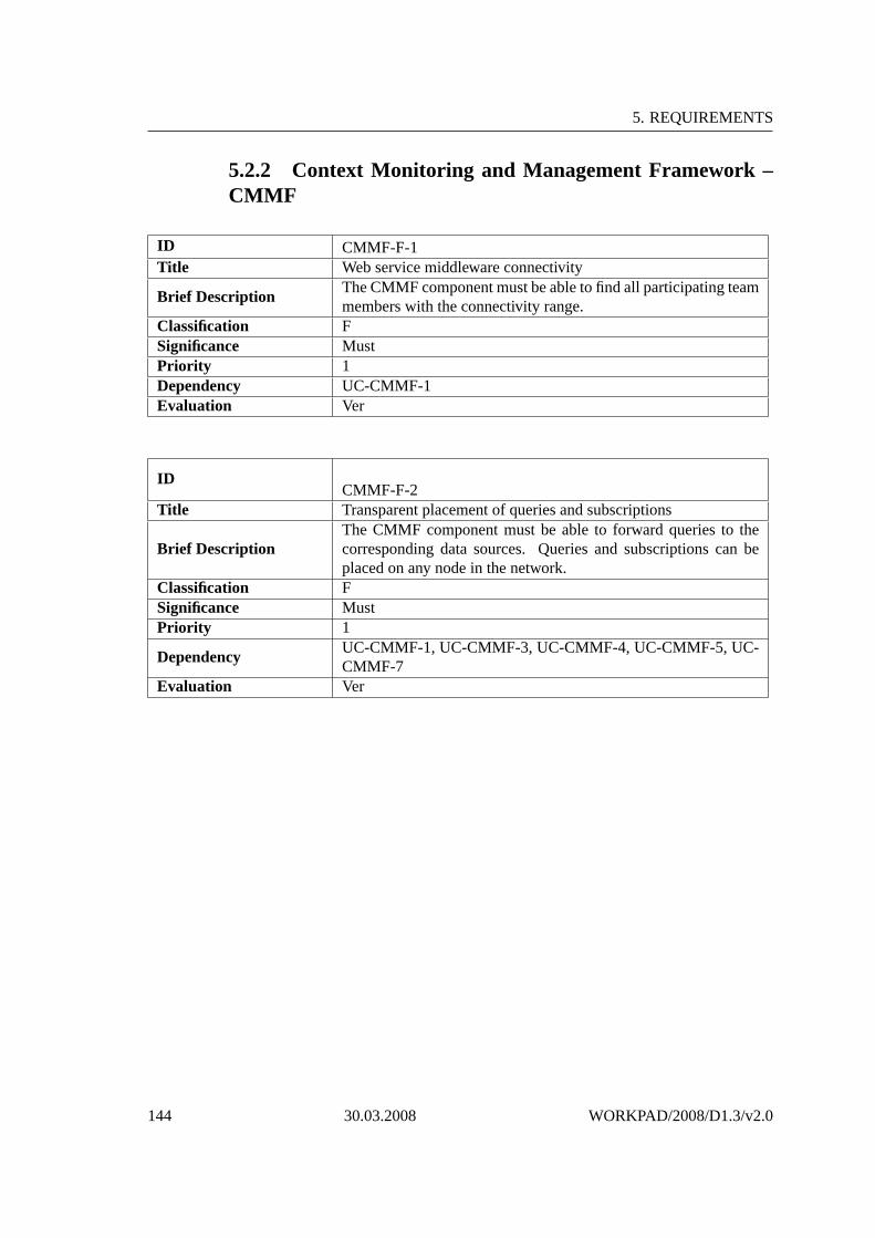
5. REQUIREMENTS
5.2.2 Context Monitoring and Management Framework –CMMF
ID CMMF-F-1Title Web service middleware connectivity
Brief DescriptionThe CMMF component must be able to find all participating teammembers with the connectivity range.
Classification FSignificance MustPriority 1Dependency UC-CMMF-1Evaluation Ver
IDCMMF-F-2
Title Transparent placement of queries and subscriptions
Brief DescriptionThe CMMF component must be able to forward queries to thecorresponding data sources. Queries and subscriptions can beplaced on any node in the network.
Classification FSignificance MustPriority 1
DependencyUC-CMMF-1, UC-CMMF-3, UC-CMMF-4, UC-CMMF-5, UC-CMMF-7
Evaluation Ver
144 30.03.2008 WORKPAD/2008/D1.3/v2.0

D1.3 Requirements Analysis(Version 2.0) Project FP6-2005-IST-5-034749
IDCMMF-F-3
Title Context can be read an manipulated by the team members.
Brief DescriptionThe CMMF component must be able to store various kinds ofcontext data and to provide this context data to all clients in thenetwork.
Classification FSignificance MustPriority 1
DependencyUC-CMMF-1, UC-CMMF-2, UC-CMMF-3, UC-CMMF-4, UC-CMMF-5, UC-CMMF-6, UC-CMMF-7
Evaluation Ver
IDCMMF-F-4
Title System must be able to detect and remove redundant information.
Brief DescriptionThe CMMF component must be able to detect and remove dupli-cate information.
Classification FSignificance MustPriority 1Dependency UC-CMMF-2, UC-CMMF-6Evaluation Ver
IDCMMF-F-5
TitleSystem must be able to detect and remove conflicting informa-tion.
Brief DescriptionThe CMMF component must be able to detect and resolve con-flicting information.
Classification FSignificance MustPriority 1Dependency UC-CMMF-2, UC-CMMF-6Evaluation Ver
IDCMMF-F-6
Title System must be able to merge information.
Brief DescriptionThe CMMF component must be able to merge information withthe existing information to represent the complete information.
Classification FSignificance MustPriority 1Dependency UC-CMMF-2, UC-CMMF-6Evaluation Ver
WORKPAD/2008/D1.3/v2.0 30.03.2008 145

5. REQUIREMENTS
5.2.3 The MANET Management
ID MANET-F-1
TitleWORKPAD devices must be able to set up WIFI connectionswith other devices in the team.
Brief DescriptionA MANET device can establish, manage and disconnect the com-munication with other MANET device within the same work-group through WiFi technology.
Classification FSignificance MustPriority 1Dependency UC-MANET-3Evaluation Ver
IDMANET-F-2
TitleThe MANET component must be able to support different Win-dows Platforms running on the WORKPAD devices.
Brief DescriptionThe PDA’s System Operative should be preferably a WindowsPlatform as Pocket PC 2003 or Windows Mobile 5.
Classification FSignificance ShallPriority 1Dependency UC-MANET-1, UC-MANET-2, UC-MANET-3Evaluation Ver
146 30.03.2008 WORKPAD/2008/D1.3/v2.0

D1.3 Requirements Analysis(Version 2.0) Project FP6-2005-IST-5-034749
IDMANET-F-3
TitleThe MANET component allows the WORKPAD applications tobe used in a standalone mode.
Brief DescriptionWorkpad applications should be able to work in indepent and au-tonomous way.
Classification FSignificance ShouldPriority 2Dependency UC-MANET-1, UC-MANET-2Evaluation Val
IDMANET-F-4
TitleThe MANET component must be able to assign unique numberswithin a workgroup.
Brief DescriptionEach team member has an identifier number, which can’t be du-plicated within the MANET or work-group.
Classification FSignificance ShouldPriority 2Dependency UC-MANET-3Evaluation Val
IDMANET-F-5
Title A MANET device must contain robust hardware.
Brief DescriptionThe MANET devices contain robust hardware that is able to sup-port all communications, data and services over it.
Classification FSignificance ShouldPriority 2Dependency UC-MANET-3Evaluation Ver
WORKPAD/2008/D1.3/v2.0 30.03.2008 147

5. REQUIREMENTS
IDMANET-F-6
Title
The MANET component shall provide communication mecha-nisms to higher level user applications to collaborate, exchangedata, and make use of services and information when operatingin the field.
Brief DescriptionThe MANET component shall provide communications manage-ment, data and information exchanges and distributed services ina secure mode among team members that work in the field.
Classification FSignificance ShallPriority 2Dependency UC-MANET-1, UC-MANET-2Evaluation Val
ID MANET-PTS-1Title The MANET component should be energy efficient.Brief Description An energy efficient compoment allows to save cost and autonomy.Classification PTSSignificance ShouldPriority 3Dependency UC-MANET-1, UC-MANET-2Evaluation Ver
IDMANET-PTS-2
TitleThe MANET component shall provide secure wireless commu-nication, intrustion detection, cryptography and protocol verifica-tion.
Brief Description
Security mechanisms are required to avoid intrusions in the com-munications, fake information inserted in the network, identitysupplanting, etc. The communications should be secure commu-nications.
Classification PTSSignificance ShouldPriority 2Dependency UC-MANET-1, UC-MANET-2Evaluation Val
148 30.03.2008 WORKPAD/2008/D1.3/v2.0

D1.3 Requirements Analysis(Version 2.0) Project FP6-2005-IST-5-034749
IDMANET-PTS-3
TitleThe MANET component shall provide secure wireless commu-nication, intrustion detection, cryptography and protocol verifica-tion.
Brief Description
Security mechanisms are required to avoid intrusions in the com-munications, fake information inserted in the network, identitysupplanting, etc. The communications should be secure commu-nications.
Classification PTSSignificance ShouldPriority 2Dependency UC-MANET-1, UC-MANET-2Evaluation Val
WORKPAD/2008/D1.3/v2.0 30.03.2008 149
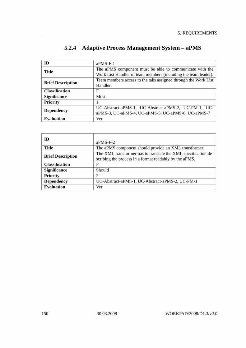
5. REQUIREMENTS
5.2.4 Adaptive Process Management System – aPMS
ID aPMS-F-1
TitleThe aPMS component must be able to communicate with theWork List Handler of team members (including the team leader).
Brief DescriptionTeam members access to the taks assigned through the Work ListHandler.
Classification FSignificance MustPriority 1
DependencyUC-Abstract-aPMS-1, UC-Abstract-aPMS-2, UC-PM-1, UC-aPMS-3, UC-aPMS-4, UC-aPMS-5, UC-aPMS-6, UC-aPMS-7
Evaluation Ver
IDaPMS-F-2
Title The aPMS component should provide an XML transformer.
Brief DescriptionThe XML transformer has to translate the XML specification de-scribing the process in a format readably by the aPMS.
Classification FSignificance ShouldPriority 2Dependency UC-Abstract-aPMS-1, UC-Abstract-aPMS-2, UC-PM-1Evaluation Ver
150 30.03.2008 WORKPAD/2008/D1.3/v2.0

D1.3 Requirements Analysis(Version 2.0) Project FP6-2005-IST-5-034749
IDaPMS-F-3
TitleThe aPMS component must be able to assign tasks without anyintervention of the team leader.
Brief DescriptionWhen a process is loaded into the aPMS engine, it has to assigntasks automatically, without any intervention of the team leader.
Classification FSignificance MustPriority 1Dependency UC-Abstract-aPMS-1, UC-Abstract-aPMS-2, UC-aPMS-7Evaluation Ver
ID aPMS-D-1
TitleThe data provided by the aPMS should be described in XML for-mat.
Brief Description
The XML language is a markup language allowing users to de-fine their own elements facilitating the sharing of structured dataacross different information systems exploiting a volatile connec-tion.
Classification DSignificance ShouldPriority 2Dependency UC-Abstract-aPMS-1Evaluation Ver
ID aPMS-PTS-1
TitleWhen a process is loaded into the aPMS engine, it shall start theassignation of the tasks after not more than 10 seconds.
Brief DescriptionThe algorithm running in the aPMS engine shall be able to startimmediately the assignation of tasks after the loading of a pro-cess.
Classification PTSSignificance ShallPriority 2Dependency UC-Abstract-aPMS-1, UC-aPMS-1Evaluation Ver
WORKPAD/2008/D1.3/v2.0 30.03.2008 151

5. REQUIREMENTS
ID aPMS-PTS-2
TitleThe aPMS component, as the whole P2P network, must be capa-ble to function even if some nodes of the network are not avail-able.
Brief DescriptionThe aPMS component must be able to adapt emergency manage-ment processes by postponing or skipping those tasks for whichno actor is available.
Classification PTSSignificance MustPriority 1Dependency UC-Abstract-aPMS-1, UC-Abstract-aPMS-2Evaluation Ver
ID aPMS-PTS-3Title Processes should not remain stalled for more than 30 seconds.
Brief DescriptionThe adaptive algorithm running into the aPMS engine shall beable to re-assign tasks, when a disconnection or a task failurehappens, as quickly as possible in order to fulfil the situation.
Classification PTSSignificance ShallPriority 2Dependency UC-Abstract-aPMS-1, UC-PM-1Evaluation Ver
152 30.03.2008 WORKPAD/2008/D1.3/v2.0

D1.3 Requirements Analysis(Version 2.0) Project FP6-2005-IST-5-034749
5.2.5 GIS Front-End – GIS-FE
ID GIS-FE-F-1
TitleThe GIS-FE component must be able to group geographic infor-mation to layers.
Brief DescriptionSuch groups could denote, for instance, streets, rivers, buildings,people etc.
Classification FSignificance MustPriority 1Dependency UC-GIS-FE-1Evaluation Val
IDGIS-FE-F-2
TitleThe GIS-FE component must provide the possibility to show orhide the geographic information.
Brief DescriptionGeographic information can be grouped to layers, where severallayers can be displayed at the same time.
Classification FSignificance MustPriority 1Dependency UC-GIS-FE-1Evaluation Val
WORKPAD/2008/D1.3/v2.0 30.03.2008 153

5. REQUIREMENTS
IDGIS-FE-F-3
TitleThe GIS-FE component must be able to distribute geographic in-formation to all reachable peers belonging to one peer group.
Brief DescriptionThe benefit of such a system is that processed information is ac-cessible to other peers in the network without requiring a centralunit.
Classification FSignificance MustPriority 1Dependency UC-GIS-FE-1Evaluation Ver
IDGIS-FE-F-4
TitleOne peer in the peer group must be able to persist data into theBE - possibly via a multi-hop path.
Brief Description Not every peer needs to have a direct link to the BE.Classification FSignificance MustPriority 1Dependency UC-GIS-FE-10Evaluation Ver
IDGIS-FE-F-5
TitleConnectivity between the peers within one peer group runningthe GIS FE application must be establishable.
Brief DescriptionThe GIS FE provides a basic peer group management to addressand set-up communication links to other peers over a MANET.
Classification FSignificance MustPriority 1Dependency UC-GIS-FE-10Evaluation Ver
IDGIS-FE-F-6
TitleThe GIS-FE component must provide the possibility to create andannotate specific points-of-interests (POI).
Brief Description It must be possible to modify and delete such POIs.Classification FSignificance MustPriority 1Dependency UC-GIS-FE-3Evaluation Ver
154 30.03.2008 WORKPAD/2008/D1.3/v2.0

D1.3 Requirements Analysis(Version 2.0) Project FP6-2005-IST-5-034749
IDGIS-FE-F-7
TitleThe GIS-FE component must provide appropriate interfaces tointeract with the underlying data model to add/delete/change geo-data (i.e., objects).
Brief DescriptionThe GIS FE system is basically separated into the necessary busi-ness logic and an (internal) data model.
Classification FSignificance MustPriority 1Dependency UC-GIS-FE-5, UC-GIS-FE-9, UC-GIS-FE-10Evaluation Ver
IDGIS-FE-F-8
TitleThe geography application should provide a minimum of threedifferent pre-defined zoom levels.
Brief DescriptionClassification FSignificance ShouldPriority 3Dependency UC-GIS-FE-1Evaluation Ver
WORKPAD/2008/D1.3/v2.0 30.03.2008 155

5. REQUIREMENTS
ID GIS-FE-PTS-1
TitleThe GIS-FE component must provide means to distribute datawithin the peer group.
Brief DescriptionInformation can be acquired or inserted at one peer and then needsto be distributed to all other peers in the peer group.
Classification PTSSignificance MustPriority 1Dependency UC-GIS-FE-11Evaluation Ver
IDGIS-FE-PTS-2
TitleThe GIS-FE component shall provide techniques to deal withsteady disconnections.
Brief DescriptionMobile environments are prone to frequent disconnections. Thecommunication infrastructure and appropriate distribution mech-anisms shall tackle this.
Classification PTSSignificance ShallPriority 2Dependency UC-GIS-FE-11Evaluation Ver
156 30.03.2008 WORKPAD/2008/D1.3/v2.0

D1.3 Requirements Analysis(Version 2.0) Project FP6-2005-IST-5-034749
IDGIS-FE-PTS-3
TitleA consistent data view (among all peers in one peer group) shallbe established after 5 seconds after an update.
Brief DescriptionDue to the distributed system architecture (P2P network) data willbe generated frequently and distributed. Hence, inconsistency be-tween data items is natural. This shall be resolved quickly.
Classification PTSSignificance ShallPriority 2Dependency UC-GIS-FE-11Evaluation Ver
WORKPAD/2008/D1.3/v2.0 30.03.2008 157

5. REQUIREMENTS
ID GIS-FE-U-1Title The GIS-FE component must be usable with a stylus.
Brief DescriptionPDAs seem to be appropriate platforms for WORKPAD scenar-ios. Hence, stylus-based interaction seems to be beneficial.
Classification USignificance MustPriority 1Dependency UC-GIS-FE-1, UC-GIS-FE-3, UC-GIS-FE-4, UC-GIS-FE-8Evaluation Val
IDGIS-FE-U-2
TitleThe GIS-FE component must provide standard map interactionfunctions such as pan, zoom, rotate, and load map.
Brief Description Minimally, standard map interaction functions are required.Classification USignificance MustPriority 1Dependency UC-GIS-FE-1, UC-GIS-FE-3, UC-GIS-FE-8Evaluation Val
IDGIS-FE-U-3
TitleThe GIS-FE component should additionally be usable by touch-ing the screen without any extra device.
Brief DescriptionTo provide more convenience, the interaction with the portabledevice should also be possible with bare fingers.
Classification USignificance ShouldPriority 3Dependency UC-GIS-FE-1, UC-GIS-FE-3,UC-GIS-FE-4, UC-GIS-FE-8Evaluation Val
158 30.03.2008 WORKPAD/2008/D1.3/v2.0

D1.3 Requirements Analysis(Version 2.0) Project FP6-2005-IST-5-034749
IDGIS-FE-U-4
TitleThe GIS-FE component must be able to present map-based, geo-feature-based and text data on the screen of a portable device.
Brief DescriptionIn the GIS FE, map-based data are enriched with geo-features(vector-based) and text (such as annotations).
Classification USignificance MustPriority 1Dependency UC-GIS-FE-1, UC-GIS-FE-2,UC-GIS-FE-3Evaluation Val
IDGIS-FE-U-5
TitleThe GIS-FE component should be able to present to geo-referenced photos.
Brief DescriptionIcons representing the presence of a geo-referenced photo shouldbe displayable. It should be possible to display that photo onscreen.
Classification USignificance ShouldPriority 3Dependency UC-GIS-FE-1, UC-GIS-FE-2,UC-GIS-FE-3Evaluation Val
IDGIS-FE-U-6
TitleThe geography application should display relevant longitude andlatitude coordinates, a scale, and the orientation.
Brief DescriptionClassification USignificance ShouldPriority 3Dependency UC-GIS-FE-1Evaluation Val
WORKPAD/2008/D1.3/v2.0 30.03.2008 159

5. REQUIREMENTS
ID GIS-FE-D-1
TitleThe GIS-FE component must be able to model and process map-based, geo-feature-based and text data on the screen of a portabledevice.
Brief DescriptionThe internal data model must be designed to be able to gathersuch information.
Classification DSignificance MustPriority 1Dependency UC-GIS-FE-1, UC-GIS-FE-2,UC-GIS-FE-3Evaluation Ver
IDGIS-FE-D-2
TitleThe GIS-FE component should be able to provide access to geo-referenced photos.
Brief Description Photos and their geo-reference should be storable.Classification DSignificance ShouldPriority 3Dependency UC-GIS-FE-1, UC-GIS-FE-2,UC-GIS-FE-3Evaluation Ver
IDGIS-FE-D-3
TitleThe GIS-FE component must be able to interface to and integratecontext data.
Brief DescriptionFor the GIS FE the most important context information is locationwhich must be provided.
Classification DSignificance MustPriority 1Dependency UC-GIS-FE-6Evaluation Ver
160 30.03.2008 WORKPAD/2008/D1.3/v2.0

D1.3 Requirements Analysis(Version 2.0) Project FP6-2005-IST-5-034749
IDGIS-FE-D-4
TitleThe GIS-FE component must use a data model approach that al-lows querying context data, distributing data to other peers over aMANET, and rendering it on the screen of a portable device.
Brief DescriptionThe data model must be flexible and extensible to address thesedifferent contexts of use.
Classification DSignificance MustPriority 1
DependencyUC-GIS-FE-1, UC-GIS-FE-2, UC-GIS-FE-3, UC-GIS-FE-6,UC-GIS-FE-11
Evaluation Ver
WORKPAD/2008/D1.3/v2.0 30.03.2008 161
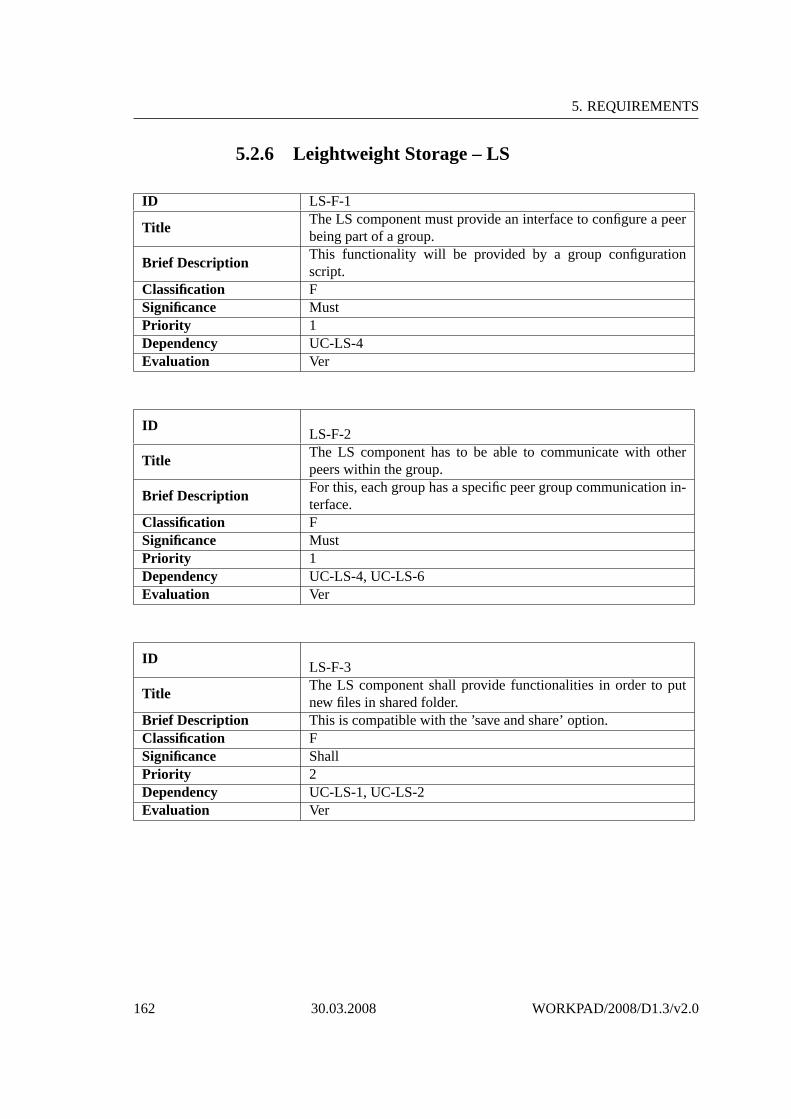
5. REQUIREMENTS
5.2.6 Leightweight Storage – LS
ID LS-F-1
TitleThe LS component must provide an interface to configure a peerbeing part of a group.
Brief DescriptionThis functionality will be provided by a group configurationscript.
Classification FSignificance MustPriority 1Dependency UC-LS-4Evaluation Ver
IDLS-F-2
TitleThe LS component has to be able to communicate with otherpeers within the group.
Brief DescriptionFor this, each group has a specific peer group communication in-terface.
Classification FSignificance MustPriority 1Dependency UC-LS-4, UC-LS-6Evaluation Ver
IDLS-F-3
TitleThe LS component shall provide functionalities in order to putnew files in shared folder.
Brief Description This is compatible with the ’save and share’ option.Classification FSignificance ShallPriority 2Dependency UC-LS-1, UC-LS-2Evaluation Ver
162 30.03.2008 WORKPAD/2008/D1.3/v2.0

D1.3 Requirements Analysis(Version 2.0) Project FP6-2005-IST-5-034749
IDLS-F-4
TitleThe LS component must implement a way to send shared files topeers within the group.
Brief DescriptionEach peer in a group must be reachable via a group address (sim-ilar to a multicast).
Classification FSignificance MustPriority 1Dependency UC-LS-5Evaluation Ver
IDLS-F-5
TitleThe LS component must provide a search functionality in orderto find useful data in other peers’ shared folders.
Brief Description A search dialog will be provided for doing so.Classification FSignificance MustPriority 1Dependency UC-LS-3Evaluation Ver
IDLS-F-6
TitleThe LS component must offer the opportunity to download filescoming from a search.
Brief Description All files returned from a query.Classification FSignificance MustPriority 1Dependency UC-LS-7Evaluation Ver
IDLS-F-7
TitleThe LS component shall notify other peers of any change on itsshared folder.
Brief DescriptionThis shall be accomplished in a transparent way without requiringexplicit user input.
Classification FSignificance ShallPriority 1Dependency UC-LS-3Evaluation Ver
WORKPAD/2008/D1.3/v2.0 30.03.2008 163

5. REQUIREMENTS
IDLS-F-8
TitleThe LS component should provide a connected peers browsingfunctionality.
Brief Description All connected peer should be displayable and browseable.Classification FSignificance ShouldPriority 3Dependency UC-LS-4Evaluation Ver
ID LS-D-1
TitleThe LS component should provide a folder to store shared files,e.g. files downloaded from other peers or downloadable fromthem.
Brief DescriptionThis folder can be defined also by default in a platform indepen-dent way.
Classification DSignificance ShouldPriority 3Dependency UC-LS-2Evaluation Ver
164 30.03.2008 WORKPAD/2008/D1.3/v2.0

D1.3 Requirements Analysis(Version 2.0) Project FP6-2005-IST-5-034749
5.2.7 Multimedia Editor – MME
ID MME-F-1
TitleThe MME component must be able to present images and videosin an appropriate way.
Brief Description
The application, which will be responsible for presenting imagesmust be 100 % compatible with used device. Such application isPhoto & Video, that runs on every OS Windows Mobile 5.0 andhigher.
Classification FSignificance MustPriority 1Dependency UC-MME-5Evaluation Val
IDMME-F-2
Title
The multimedia application must be able to provide functionali-ties such as open, save, close, delete, and rename a multimediafile; in addition further functionalities such as cropping, resizing,zooming, changing brightness, and rotating must be provided.
Brief Description
That means the multimedia application provides functionalityfor opening, saving, closing, deleting, and renaming multimediafiles; and some special functions like cropping, resizing, zoom-ing, changing brightness, and rotating.
Classification FSignificance MustPriority 1Dependency UC-MME-5Evaluation Val
WORKPAD/2008/D1.3/v2.0 30.03.2008 165

5. REQUIREMENTS
ID MME-D-1
TitleThe MME component must provide interfaces to the LS compo-nent.
Brief Description The interface is needed for sharing multimedia data.Classification DSignificance MustPriority 1Dependency UC-MME-1, UC-MME-2Evaluation Val
IDMME-D-2
Title The MME component must support standard image formats.
Brief DescriptionUsers need to work with images in various, but standard, formats,this must be available without problems.
Classification DSignificance MustPriority 1Dependency UC-MME-1, UC-MME-2, UC-MME-5,UC-MME-6Evaluation Val
IDMME-D-3
Title The device must have filesystem.Brief Description Multimedia application needs filesystem for storing files.Classification DSignificance MustPriority 1Dependency UC-MME-4, UC-MME-5,UC-MME-6Evaluation Ver
166 30.03.2008 WORKPAD/2008/D1.3/v2.0

D1.3 Requirements Analysis(Version 2.0) Project FP6-2005-IST-5-034749
5.2.8 Context Editor – CE
ID CE-F-1
TitleThe Context Editor must be able to support DOM-based process-ing of documents.
Brief Description That is crucial for processing data from/to XML documents.Classification FSignificance MustPriority 1Dependency UC-CE-10Evaluation Ver
IDCE-F-2
Title The Context Editor must support XMLHttpRequests.
Brief DescriptionThat is used for transfer XML data between client to server; Con-text Editor to CMMF.
Classification FSignificance MustPriority 1Dependency UC-CE-10Evaluation Ver
IDCE-F-3
Title The Context Editor must be able to execute XPATH queries.Brief Description That is needed for receiving relevant data from XML files.Classification FSignificance MustPriority 1Dependency UC-CE-10Evaluation Ver
WORKPAD/2008/D1.3/v2.0 30.03.2008 167

5. REQUIREMENTS
ID CE-D-1
TitleThe Context Editor must provide interfaces to the CMMF com-ponent.
Brief DescriptionIt must be available to transfer data from/to Context Editorto/from CMMF.
Classification DSignificance MustPriority 1Dependency UC-CE-10Evaluation Ver
168 30.03.2008 WORKPAD/2008/D1.3/v2.0

D1.3 Requirements Analysis(Version 2.0) Project FP6-2005-IST-5-034749
5.2.9 Process Miner – PM
ID PM-F-1Title The system must be able to handle inputs specified by the user.
Brief DescriptionThe process miner will handle inputs such as logs, processschemas and user-specific requirements.
Classification FSignificance MustPriority 1Dependency UC-PM-2, UC-PM-3, UC-PM-4Evaluation Ver
IDPM-F-2
Title Mining results must be stored.
Brief DescriptionThe Process Miner must be able to store mining results, such asperformance, failures and interaction, into a repository.
Classification FSignificance MustPriority 1Dependency UC-PM-2, UC-PM-3, UC-PM-4Evaluation Ver
IDPM-F-3
Title The system must be able to handle incomplete log information.Brief Description Log information for processes might not be complete.Classification FSignificance MustPriority 1Dependency UC-PM-2, UC-PM-3, UC-PM-4Evaluation Ver
WORKPAD/2008/D1.3/v2.0 30.03.2008 169

5. REQUIREMENTS
5.2.10 GIS Back-End – GIS-BE
ID GIS-BE-F-1
TitleThe GIS-BE component must provide means to exchange andconfigure different GIS servers (GIS datasources).
Brief DescriptionGIS systems use different interfaces and implementations (stan-dards) for data access. The system has to cope with these differentsystems.
Classification FSignificance MustPriority 1Dependency UC-GIS-BE-6Evaluation Ver
IDGIS-BE-F-2
TitleThe GIS-BE component must provide means to retrieve geo-graphic features.
Brief DescriptionThe system has to provide non-image data of the disaster region,like meta-information about buildings.
Classification FSignificance MustPriority 1Dependency UC-GIS-BE-5, UC-GIS-BE-7Evaluation Ver
170 30.03.2008 WORKPAD/2008/D1.3/v2.0

D1.3 Requirements Analysis(Version 2.0) Project FP6-2005-IST-5-034749
IDGIS-BE-F-3
TitleThe GIS-BE component must provide means to store geographicfeatures.
Brief Description
Changes may occur to geographical data during a disaster (forexample, a brige may collaps). The system has to be able to copewith changes gathered by teams during disasters, and has to allowthese changes to be stored in th correct DB.
Classification FSignificance MustPriority 1Dependency UC-GIS-BE-2Evaluation Ver
IDGIS-BE-F-4
TitleThe GIS-BE component should be able to provide notificationsabout changes in geographic features.
Brief Description
If a change occurs in the Geo-Database of one of the geo-dataproviders, these changes have to be propagated to all interestingparties. Therefor, a subscrition mechanism should be used fornotification of changes.
Classification FSignificance ShouldPriority 2Dependency UC-GIS-BE-3, UC-GIS-BE-4Evaluation Ver
IDGIS-BE-F-5
TitleThe GIS-BE component must uniquely identify geographic fea-tures.
Brief DescriptionIn order to access geographical features from different sourcesand to provide mapping to tuples, these feature have to beuniquely identified across all systems.
Classification FSignificance MustPriority 1Dependency UC-GIS-BE-9, UC-GIS-BE-10Evaluation Ver
WORKPAD/2008/D1.3/v2.0 30.03.2008 171

5. REQUIREMENTS
IDGIS-BE-F-6
TitleThe GIS-BE component must provide means to configure the GISdatasources to use.
Brief Description
Different sources (at least databases, the DI sub-system as wellas geodata providers (Geoservers) have been identified as possi-ble geo datasource for the Back-End. The system should providemeans to allow the configuration of these services.
Classification FSignificance MustPriority 1Dependency UC-GIS-BE-6Evaluation Ver
IDGIS-BE-F-7
TitleThe GIS-BE component must be able to integrate different GISdatasources.
Brief Description
Currently, GIS datasources are only integrated on a syntactic level(i.e. it is possible to access different GIS services using the sameprotocolls. By allowing semantic data integration of different GISservices, one can for example asure, that the concept of a ”street”is the same in these different services.
Classification FSignificance MustPriority 1Dependency UC-GIS-BE-6Evaluation Ver
IDGIS-BE-F-8
TitleThe GIS-BE component must be able to uniquely identify differ-ent features from different sources. The system must provide amapping to these sources.
Brief Description
In order to allow the backtracking of different features to differ-ent sources, features have to be uniquely identified accross thesystem. This may be done using an URN-schema including thesource of the feature.
Classification FSignificance MustPriority 1Dependency UC-GIS-BE-6Evaluation Ver
172 30.03.2008 WORKPAD/2008/D1.3/v2.0

D1.3 Requirements Analysis(Version 2.0) Project FP6-2005-IST-5-034749
IDGIS-BE-F-9
TitleThe GIS-BE component must provide means to retrieve geo-graphic maps.
Brief DescriptionIn addition to the ability to provide geogrpahic features, the Back-End system has to be able to provide an image represeantation ofthe disaster region.
Classification FSignificance MustPriority 1Dependency UC-GIS-BE-8Evaluation Ver
WORKPAD/2008/D1.3/v2.0 30.03.2008 173

5. REQUIREMENTS
5.2.11 P2P Data Integration – DI
ID DI-PTS-1
TitleThe P2P component should guarantee autonomy and flexibility ofparticipants of a P2P network.
Brief DescriptionThe network should be able to dynamically integrate and manage(new) peers.
Classification PTSSignificance ShouldPriority 2
DependencyUC-DI-1, UC-DI-2, UC-DI-3, UC-DI-4, UC-DI-5, UC-DI-6,UC-DI-7
Evaluation Ver
IDDI-PTS-2
TitleThe P2P component, as the whole p2p network, must be capableto function even if some nodes of the network are not available.
Brief DescriptionEach BE peer continue to provide services to its clients and toother nodes even if some other peers are unreachable.
Classification PTSSignificance MustPriority 1Dependency UC-DI-8Evaluation Ver
IDDI-PTS-3
Title The P2P component should be scalable of peer.
Brief DescriptionThe query answering should support a number of sources andpeers and give responses in a reasonable time.
Classification PTSSignificance ShouldPriority 2DependencyEvaluation Ver
174 30.03.2008 WORKPAD/2008/D1.3/v2.0

D1.3 Requirements Analysis(Version 2.0) Project FP6-2005-IST-5-034749
IDDI-PTS-4
TitleThe query engine must realize improvement with respect to tra-ditional systems.
Brief Description
The query engine must realize a 5-50 percent improvement withrespect to similar traditional systems that provide similar capa-bilities. In order to conduct the benchmarks similar traditionalsystem will be chosen, investigated and confronted with the re-sult of the WORKPAD assessments.
Classification PTSSignificance MustPriority 2Dependency UC-DI-8Evaluation Ver
IDDI-PTS-5
Title The P2P component should have secure access to the BE.
Brief DescriptionMission-critical data of various stakeholders may be used andtransferred. This data should be secured accordingly.
Classification PTSSignificance ShouldPriority 2Dependency UC-DI-8Evaluation Ver
IDDI-PTS-6
TitleThe P2P component must be available for the period of the emer-gency (ideally 24x7).
Brief Description N/AClassification PTSSignificance MustPriority 1Dependency UC-DI-8, UC-DI-9, UC-DI-11Evaluation Ver
IDDI-PTS-7
TitleThe P2P component must allow concurrent access form clients tothe query engine.
Brief Description Each peer must support concurrency in query answering.Classification PTSSignificance MustPriority 1Dependency UC-DI-8Evaluation Ver
WORKPAD/2008/D1.3/v2.0 30.03.2008 175

5. REQUIREMENTS
IDDI-PTS-8
Title The P2P component should preserve data integrity.
Brief DescriptionThe system should guarantee that data are identically maintainedduring any operation (such as query answering) in order to main-tain data consistency and correctness.
Classification PTSSignificance ShouldPriority 2Dependency UC-DI-8, UC-DI-9Evaluation Ver
176 30.03.2008 WORKPAD/2008/D1.3/v2.0

D1.3 Requirements Analysis(Version 2.0) Project FP6-2005-IST-5-034749
ID DI-F-1
TitleThe P2P component must be able to integrate heterogeneous datasources and provide them through a uniform interface.
Brief Description
BE must abstract logical and physical data models by hiding im-plementations of data providers. To alleviate information accessand to address interoperability, well-known interfaces must beprovided.
Classification FSignificance MustPriority 1Dependency UC-DI-6, UC-DI-7, UC-DI-8Evaluation Ver
IDDI-F-2
Title The P2P component must allow meaningful queries.
Brief DescriptionThe system must allow participants to perform meaningfulqueries to data by accessing own organization’s peer.
Classification FSignificance MustPriority 1Dependency UC-DI-8Evaluation Ver
WORKPAD/2008/D1.3/v2.0 30.03.2008 177

5. REQUIREMENTS
IDDI-F-3
Title The P2P component should support semantic query mechanism.
Brief DescriptionThe System should answer queries over knowledge using reason-ing and semantic integration.
Classification FSignificance ShouldPriority 2Dependency UC-DI-8Evaluation Ver
IDDI-F-4
TitleThe P2P component should support complex FE workflows byexposing a query interface over invoked data.
Brief DescriptionComplex workflows are integral part in emergency management.WORKPAD support adaptive process management and the BEshould support it providing access to needed data.
Classification FSignificance ShouldPriority 2Dependency UC-DI-8Evaluation Ver
IDDI-F-5
TitleThe P2P component must support notification of information up-dates to interested parties
Brief DescriptionPeers can announce their interest in specific data. As soon as therelevant events happen, the peers are notified.
Classification FSignificance MustPriority 1Dependency UC-DI-9, UC-DI-11Evaluation Ver
178 30.03.2008 WORKPAD/2008/D1.3/v2.0

D1.3 Requirements Analysis(Version 2.0) Project FP6-2005-IST-5-034749
ID DI-U-1
TitleThe P2P component must allow rapid configuration of a new nodeentering the network.
Brief DescriptionOnce the peer’s resources are defined, must be easy to plug thenew peer in the BE network.
Classification USignificance MustPriority 1Dependency UC-DI-2, UC-DI-3, UC-DI-5, UC-DI-6Evaluation Ver
IDDI-U-2
TitleThe P2P component should offer a graphical interface to modelknowledge through ontologies.
Brief DescriptionIn order to help to define peer’s own ontology and mappings to-ward defined sources and other peers, a usable graphical interfaceshould be provided.
Classification USignificance ShouldPriority 2Dependency UC-DI-1, UC-DI-2Evaluation Val
IDDI-U-3
Title The P2P component should aid the user to define sources.
Brief DescriptionIn order to facilitate the peer’s sources definition the systemshould permit the user to introspect the sources’ schemas.
Classification USignificance ShouldPriority 2Dependency UC-DI-6, UC-DI-7Evaluation Val
WORKPAD/2008/D1.3/v2.0 30.03.2008 179

5. REQUIREMENTS
IDDI-U-4
TitleA single administration tool should allows managing the BE P2Pnetwork.
Brief DescriptionIn order to improve usability and user-friendliness one single GUIshould be realized.
Classification USignificance ShouldPriority 2
DependencyUC-DI-1, UC-DI-2, UC-DI-3, UC-DI-4, UC-DI-5, UC-DI-6,UC-DI-7
Evaluation Val
180 30.03.2008 WORKPAD/2008/D1.3/v2.0

D1.3 Requirements Analysis(Version 2.0) Project FP6-2005-IST-5-034749
ID DI-D-1
TitleThe participants of the BE P2P network must be able to requestdata stored in the various peers of the BE.
Brief DescriptionThe BE must provide the possibility (to other WORKPAD enti-ties) to access data kept in the BE infrastructure.
Classification DSignificance MustPriority 1Dependency UC-DI-8, UC-DI-11Evaluation Ver
IDDI-D-2
TitleThe P2P component must be able to provide data of interest to theparticipant organizations.
Brief DescriptionThe participant organizations must be able to access the BE sys-tem knowledge in order to perform queries useful to retrieve dataof interest.
Classification DSignificance MustPriority 1Dependency UC-DI-8Evaluation Ver
WORKPAD/2008/D1.3/v2.0 30.03.2008 181
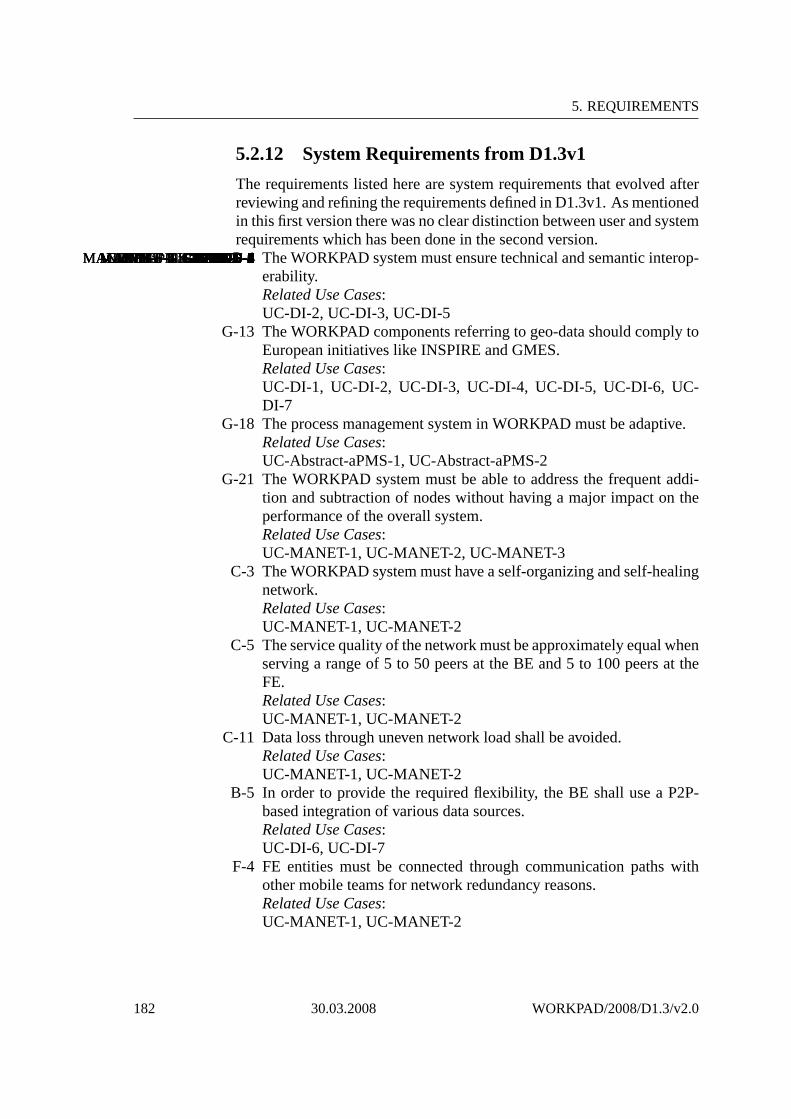
5. REQUIREMENTS
5.2.12 System Requirements from D1.3v1
The requirements listed here are system requirements that evolved afterreviewing and refining the requirements defined in D1.3v1. Asmentionedin this first version there was no clear distinction between user and systemrequirements which has been done in the second version.
WH-F-1WH-F-2WH-F-3CMMF-F-1CMMF-F-2CMMF-F-3CMMF-F-4CMMF-F-5CMMF-F-6MANET-F-1MANET-F-2MANET-F-3MANET-F-4MANET-F-5MANET-F-6MANET-PTS-1MANET-PTS-2MANET-PTS-3aPMS-F-1aPMS-F-2aPMS-F-3aPMS-D-1aPMS-PTS-1aPMS-PTS-2aPMS-PTS-3GIS-FE-F-1GIS-FE-F-2GIS-FE-F-3GIS-FE-F-4GIS-FE-F-5GIS-FE-F-6GIS-FE-F-7GIS-FE-F-8GIS-FE-PTS-1GIS-FE-PTS-2GIS-FE-PTS-3GIS-FE-U-1GIS-FE-U-2GIS-FE-U-3GIS-FE-U-4GIS-FE-U-5GIS-FE-U-6GIS-FE-D-1GIS-FE-D-2GIS-FE-D-3GIS-FE-D-4LS-F-1LS-F-2LS-F-3LS-F-4LS-F-5LS-F-6LS-F-7LS-F-8LS-D-1MME-F-1MME-F-2MME-D-1MME-D-2MME-D-3CE-F-1CE-F-2CE-F-3CE-D-1PM-F-1PM-F-2PM-F-3GIS-BE-F-1GIS-BE-F-2GIS-BE-F-3GIS-BE-F-4GIS-BE-F-5GIS-BE-F-6GIS-BE-F-7GIS-BE-F-8GIS-BE-F-9DI-PTS-1DI-PTS-2DI-PTS-3DI-PTS-4DI-PTS-5DI-PTS-6DI-PTS-7DI-PTS-8DI-F-1DI-F-2DI-F-3DI-F-4DI-F-5DI-U-1DI-U-2DI-U-3DI-U-4DI-D-1DI-D-2G-4 The WORKPAD system must ensure technical and semantic interop-erability.Related Use Cases:UC-DI-2, UC-DI-3, UC-DI-5
G-13 The WORKPAD components referring to geo-data should comply toEuropean initiatives like INSPIRE and GMES.Related Use Cases:UC-DI-1, UC-DI-2, UC-DI-3, UC-DI-4, UC-DI-5, UC-DI-6, UC-DI-7
G-18 The process management system in WORKPAD must be adaptive.Related Use Cases:UC-Abstract-aPMS-1, UC-Abstract-aPMS-2
G-21 The WORKPAD system must be able to address the frequent addi-tion and subtraction of nodes without having a major impact on theperformance of the overall system.Related Use Cases:UC-MANET-1, UC-MANET-2, UC-MANET-3
C-3 The WORKPAD system must have a self-organizing and self-healingnetwork.Related Use Cases:UC-MANET-1, UC-MANET-2
C-5 The service quality of the network must be approximately equal whenserving a range of 5 to 50 peers at the BE and 5 to 100 peers at theFE.Related Use Cases:UC-MANET-1, UC-MANET-2
C-11 Data loss through uneven network load shall be avoided.Related Use Cases:UC-MANET-1, UC-MANET-2
B-5 In order to provide the required flexibility, the BE shall use a P2P-based integration of various data sources.Related Use Cases:UC-DI-6, UC-DI-7
F-4 FE entities must be connected through communication paths withother mobile teams for network redundancy reasons.Related Use Cases:UC-MANET-1, UC-MANET-2
182 30.03.2008 WORKPAD/2008/D1.3/v2.0

D1.3 Requirements Analysis(Version 2.0) Project FP6-2005-IST-5-034749
5.3 Performance Considerations for WORK-PAD Components
Performance is a critical factor of software components andis related toa later acceptance of the users (cf. response time) of a particular soft-ware product. Because of this, in this section we consider andexamineperformance issues which are related to particular performance require-ments. In this deliverable D1.3v2 relevant performance measures are de-fined which are examined and evaluated in workpackage 5 and the laterdeliverable D5.2.
5.3.1 Objectives of the Performance Analysis
Figure 5.1 describes an overview of the WORKPAD system. Deliver-ables D2.1 and D3.1 describe in detail the functionalities of these compo-nents. One of the main issues is how to ensure that WORKPAD softwarecomponents will be able to respond to user requests in a timely manner,considering that WORKPAD components operate in ad-hoc networks ofmobile devices with constrained resources and require access to back-end data under a changing network. This concerns the performance issuefor WORKPAD. Since interactions between WORKPAD software com-ponents are complex and they span different execution environments, theperformance requirement and testing are complex as well. The objectiveof this performance requirement study is to identify major points whereperformance issues should be carefully examined, not only when design-ing WORKPAD components but also when testing performance of suchcomponents.To this end, our approach in understanding performance requirements andtesting is toA. identify and characterize the dependency among main components
by means of data flowsB. survey user performance perceptions on main tasksC. derive performance requirements, andD. generate test cases for testing the performance of WORKPADcom-
ponentsThe first three points will be discussed in this deliverable (D1.3 version2), while the last point will be developed in deliverable D5.2 in the contextof workpackage 5.
5.3.2 Main Component Dependencies and Data Flows
As described in D2.1 and D3.1, WORKPAD components are developedfrom different groups using different technologies (e.g.,Java and C#) andAPIs (e.g., Web services, socket-based). Interactions among components
WORKPAD/2008/D1.3/v2.0 30.03.2008 183

5. REQUIREMENTS
Figure 5.1: Overview of WORKPAD components
are based on different APIs and data representations. Table5.2 describesmajor data exchanged between components that are extractedfrom usecases. There are use cases which are hardly executed or are minor. Forsuch use cases, we choose not to include into Table 5.2.From Table 5.2 and use cases, we derive three main typical sizes of dataexchange between components, shown in Table 5.3.We use a graphG(N,E) whereN is a set of nodes representing compo-nents andE is a set of edges representing the data dependency betweencomponents. An edgee(ni, nj) ∈ E means that there is a data depen-dency between componentni and componentnj. Eache(ni, nj) will beassociated with data being exchanged between components. Figure 5.2presents major data flows in WORKPAD among components on devicesof team members and between components of WORKPAD front-end andback-end. We choose not to show the MANET and FE-BE Gateway aswe consider them at network level basically used by most components.By using information in this graph, we can generate test casesto test theperformance of main components in particular scenarios.
184 30.03.2008 WORKPAD/2008/D1.3/v2.0

D1.3
Requirem
entsA
nalysis(Version2.0)
ProjectF
P6-2005-IS
T-5-034749
From To Data Format Data size range (KB) API FrequencyaPMS TaskHandler specific 0.1-0.5 socket very oftenTaskHandler aPMS specific 0.1-0.5 socket very oftenInstant Messaging Instant Messaging text 0.1-1 socket very oftenInstant Messaging Instant Messaging audio 3.5 socket very oftenaPMS CMMF XML 0.2-1.5 Web services very oftenCMMF aPMS XML 5-200 Web services sometimesGISClient CMMF XML 0.1-5 Web services very oftenCMMF GISClient XML 5-200 Web services very oftenContext Editor CMFF XML 1-50 Web services very oftenGISServer GISClient XML 1-10 Web services sometimesGISClient GISServer XML 1-1024 Web services sometimesMultimedia Handler Lightweight Storage MM format 1-8096 local API sometimesLightweight Storage Lightweight Storage MM format 1-8096 socket sometimes
Table 5.2: Data exchange extracted from use cases and from inputs of users and developers fora team ranging from 5-20 memberswhere”very often” is about 30 transmissions/minute and”sometimes”is about 1 transmission/minute.
WO
RK
PA
D/2008/D
1.3/v2.030.03.2008
185

5. REQUIREMENTS
Type Range Componentssmall data size 0.1-2KB aPMS, CMMF, GISClient, Instant Messagingmedium data size 2-10KB CMMF, Instant Messaging,Context Editorlarge data size 10-8096KB CMMF, Lightweight Storage, Multimedia Handler,
GISClient, GISServer, DataIntegrator
Table 5.3: Typical sizes of exchanged data
5.3.3 Survey of Performance Perceptions from Usersand Developers
From data dependency between components and main types of data ex-change, we conduct a survey of performance perceptions fromthe userand developer. This survey is used to guide the testing of individual com-ponents and the WORKPAD system to meet the expectation of the userand developer with respect to performance. Although, user and developerexpectations are expressed for specific scenarios, we can also use the in-formation given by the user and developer for testing different scenariosas well, e.g., by using extrapolation techniques to derive new expectedperformance for new scenarios or by deriving expected performance forsubcomponents of a component in a scenario based on expectedperfor-mance of the component.Table 5.4 presents the expectation obtained from end-usersand develop-ers within WORKPAD.
5.3.4 Generating Test Cases
From data dependencies and flows, we generate test cases in workpack-age 5. Test cases are generated for testing individual data flows as wellas flows involved many components. For each test case, performanceevaluation conditions will be set based on the users’ and developers’ ex-pectations. Based on that, we will check whether expectations from theusers and developers will be met under certain conditions. Detailed testcases will be presented in deliverable D5.2.
186 30.03.2008 WORKPAD/2008/D1.3/v2.0

D1.3
Requirem
entsA
nalysis(Version2.0)
ProjectF
P6-2005-IS
T-5-034749
Actor Target component Tasks Scenarios Expected time/delay (s)Team member/leader Instant Messaging Send message 5-20 members 1-2Team member/leader Instant Messaging Send audio 5-20 members 10Team member/leaderLightweight Storage Submit data to the storage 5-20 members, 50KB 10Team member/leaderLightweight Storage Get a file from the storage 5-20 members, 50KB 10Team member/leaderGISClient Annotate information 5-20 members 2Team member/leaderGISClient Show/hide geoinformation 5-20 members 2Team member/leaderGISClient Display dynamic positions 5-20 members 2GISClient CMMF Get context information 5-20 members 0.5GISClient GISServer Get GIS Data 5-20 members 5GISClient GISServer Subscribe notification 5-20 members 5GISClient GISServer Execute feature query 5-20 members 3Context Editor CMMF Set context information 5-20 members 15
Table 5.4: Survey of expected performance of components from the end-user and the developer
WO
RK
PA
D/2008/D
1.3/v2.030.03.2008
187

5. REQUIREMENTS
SmartPeer
SmartPeer/Team Leader Device
Backend
ContextEditor
CMMF
GISClient
Knowledge Access TaskHandler
aPMS
Instant Messaging
Instant Messaging
Lightweight Storage
Lightweight Storage
Multimedia Handler
CMMFProcess
Design UI
Knowledge Access
GISServer DataIntegrator
Figure 5.2: Major dependencies and data flows in WORKPAD.
188 30.03.2008 WORKPAD/2008/D1.3/v2.0

Chapter 6
Summary
The deliverable D1.3 “Requirements Analysis” in its three versions is themain part of work-package one (Requirements Analysis) and addressesthe following main objectives:• Presenting the various use cases of the WORKPAD system.• Analysing and Defining the user requirements.• Analysing and Defining the system requirements.
This second version of D1.3, is based on the first version and reviewsand refines the initial requirements further. The first version was releasedearly in the project. At this stage requirements were gathered throughintensive user interaction and analysis of related works and relevant ini-tiatives (on EU and national levels). As a result, a catalog of requirementswas developed. However, no clear distinction between user and systemrequirements could be done at that stage. This distinction was specified inthis second version at hand. Naturally, as the user involvement was veryhigh most of the initial requirements were user requirements. In D1.3v2system requirements were additionally generated through adopting usecase analyses. In addition, considerations about initial performance mea-sures are presented in this report.The outcomes, which essentially are the user and systems requirements,serve as a basis and input for the next versions of this deliverable D1.3(version 3, due in month 30) and for further works in WORKPAD, espe-cially for the related work-packages on design and implementation. Therelated front-end and back-end architectures, such as described in deliv-erables D3.1, D4.1 and D5.1, have been devised taking into account suchrequirements. These requirements will be further refined with respect touser feedbacks as well as they will be leveraged against technical issuesduring the implementation.
189

Bibliography
[BS03] K. Bittner and I. Spence.Use Case Modelling. Pearson Ed-ucation, Inc, 2003.
[Cze08a] Czech Hydrometeorological Institute, 2008. Onlineavailablefrom http://www.chmi.cz/.
[Cze08b] Czech Ministry of Interior , 2008. Online available fromhttp://www.mvcr.cz.
[Cze08c] Czech Police Presidium, 2008. Online available fromhttp://www.mvcr.cz/policie/index.html.
[DFAB98] Alan Dix, Janet Finlay, Gregory D. Abowd, and RussellBeale.Human-Computer Interaction. Prentice Hall, 1998.
[Don06] Don Juan Carlos de Borbon. Real Decree 991/2006. The Or-ganic Basic Structure of the Interior Ministry of Spain, 2006.Signed Don Juan Carlos de Borbon by 8th of September.
[Eur98] European Parliament. Application of Open Network Pro-vision (ONP) to Voice Telephony and on Universal Ser-vice for Telecommunications in a Competitive Environment,1998. Article 7.2 of Directive 98/10/EC of the Council of26 February 1998, Published in the Official Journal L 101,01/04/1998, pp. 0024 - 0047.
[Gen08] General Directorate of Fire Rescue Brigades, 2008. Onlineavailable fromhttp://www.mvcr.cz/hasici/.
[JBR99] Ivar Jacobson, Grady Booch, and James Rumbaugh.TheUnified Software Development Process. Addison Wesley,1999.
[LPLC03] S. Lu, C. Paris, Vander K. Linden, and N. Colineau. Gener-ating uml diagrams from task models. InProc. of CHINZ’03,2003.
[Mai08] Main Well control Service, 2008. Online avail-able from http://www.mnd.cz/page.php?lang=cs&p=home.
[Min08a] Ministry of Foreign Affairs, 2008. Online available fromhttp://www.mzv.cz/.
[Min08b] Ministry of Health, 2008. Online available fromhttp://www.mzcr.cz/.
190

D1.3 Requirements Analysis(Version 2.0) Project FP6-2005-IST-5-034749
[Obr06] Ivan Obrusnik. Multi Hazard Warning Service in the CzechRepublic, 2006. Presented at the Central European DisasterPrevention Forum. Available fromhttp://www.chmi.cz/katastrofy/ceudip06.html.
[Sal75] Salzburger Landesregierung. Salzburger LandesgesetzblattNr. 3/1975, amended on 50/2006: Katastrophenhilfegesetz,1975.
[Sal97] Salzburger Landesregierung. Handbuch fuer den beho-erdlichen Einsatzstab. Praesidialabteilung, Referat Katastro-phenschutz, 1997.
[SS03] Jag Sodhi and Prince Sodhi.Managing IT System Require-ments. Management Concepts, 2003.
[Sut03] A. G. Sutcliffe. Scenario-based requirements engineering. InProceedings of the 11th IEEE International Conference onRequirements Engineering, pages 320–329. IEEE ComputerSociety, 2003.
[Tir06] Tiroler Landesregierung. Tiroler Landesgesetzblatt Nr.33/2006: Tiroler Katastrophenmanagementgesetz, 2006.
[Wie00] Karl Wiegers. Karl wiegers describes 10 requirements trapsto avoid.Software Testing and Quality Engineering Journal,2(1), 2000.
[Wie06] Karl Wiegers.More About Software Requirements: ThornyIssues and Practical Advice. Microsoft Press, 2006.
[WOR07a] WORPPAD Project Consortium. Deliverable D1.3: Require-ments and Conceptual Analysis (Version 1.0), 2007.
[WOR07b] WORPPAD Project Consortium. Deliverable D2.1: TheWORKPAD Architecture, 2007.
[WOR08a] WORPPAD Project Consortium. Deliverable D3.1: Archi-tecture and Detailed Design for the Front-end, 2008.
[WOR08b] WORPPAD Project Consortium. Deliverable D3.2: Ba-sic Algorithms, Methods and Techniques for the Front-end,2008.
[WOR08c] WORPPAD Project Consortium. Deliverable D4.1: Archi-tecture and Detailed Design for the Back-end, 2008.
[WOR08d] WORPPAD Project Consortium. Deliverable D4.2: Ba-sic Algorithms, Methods and Techniques for the Back-end,2008.
[WOR08e] WORPPAD Project Consortium. Deliverable D6.1: WORK-PAD Showcases Design and Implementation, 2008.
[WOR08f] WORPPAD Project Consortium. Deliverable D6.2: Reporton the Validation Activity, 2008.
WORKPAD/2008/D1.3/v2.0 30.03.2008 191

BIBLIOGRAPHY
[ZN03] P. Zelnicek and V. Neklapilova. Integrated rescue systemin the czech republic. International Journal of DisasterMedicine, 1(2):132–133, 2003.
192 30.03.2008 WORKPAD/2008/D1.3/v2.0