d1.2 state of the art · ats air traffic system bada base of aircraft data bwb blended wing body...
TRANSCRIPT

D1.2 State of the Art Runway and airport design, ATM procedures, aircraft
The Endless Runway project intends to design a circular runway that enables aircraft to always
operate at landing and take-off with headwind. In this document, existing work on circular runways
is reviewed: previous theoretical work is analyzed, and live trials of circular runway are mentioned.
Design elements and figures on conventional runways are given; current regulations and aircraft
physical considerations are identified. Future aspects of airport, aircraft and ATM developments are
addressed and the relevance to the endless runway outlined. Other alternatives to the straight
runway are presented.
Project Number 308292 Document Identification D1.2_WP1_Background Status Final Version 3.0 Date of Issue 11/04/2014
Authors M. Dupeyrat, S. Aubry, P. Schmollgruber, A. Remiro, S. Loth,
M. Vega Ramírez, H. Hesselink, R. Verbeek, J. Nibourg
Organisation ONERA, INTA, INSA, NLR, DLR

EC DG-RTD Contract: ACP2-GA-2012-308292- ENDLESS RUNWAY
Ref.: D1.2 The Endless Runway Background Version: 3.0
Date: 11/04/2014 Page 2/161
Public
D1.2 The Endless Runway Background
Document Change Log Version Author Date Affected Sections Description of Change
0.1 DLR, ONERA, INTA, NLR 11/09/2012 All Creation of document (merging of documents)
0.2 DLR 15/09/2012 All Reordering sections review of original D1.2 part
0.3 DLR 15/09/2012 All Version for review 0.4 ONERA (S. Aubry) 27/09/2012 All Review comments incorportated 1.0 NLR 30/09/2012 All Version for delivery to EC 1.1 ONERA 31/10/2012 All Including peer review comments
by ONERA management 2.0 NLR 13/11/2012 All Version 2.0 for delivery to EC 2.1 NLR 18/02/2014 6.1 Review from EC + final meeting 3.0 NLR 11/04/2014 All Version 3.0 for delivery to EC
Document Distribution Organisation Name EC Ivan Konaktchiev NLR Henk Hesselink
Carl Welman René Verbeek Joyce Nibourg
DLR Steffen Loth ONERA Maud Dupeyrat
Sébastien Aubry Peter Schmollgruber
INTA Francisco Mugñoz Sanz María Antonia Vega Ramírez Albert Remiro
ILOT Marián Jez
Review and Approval of the Document Organisation and Persons Responsible for Review
Version provided for review Date
DLR (Steffen Loth) 0.3 18/09/2012 NLR (Henk Hesselink) 0.4 18/09/2012 ONERA (Muriel Brunet : ONERA management, Jean Hermetz : ONERA management, Maud Dupeyrat, Sébastien Aubry)
1.0 30/09/2012
ONERA (Maud Dupeyrat) NLR (Henk Hesselink)
2.0 13/11/2012
Organisation Responsible for Approval Name of person approving the document Date
NLR Henk Hesselink (Project Coordinator) 11/04/2014
EC DG-RTD Contract: ACP2-GA-2012-308292- ENDLESS RUNWAY
Ref.: D1.2 The Endless Runway Background Version: 3.0
Date: 11/04/2014 Page 3/161
Public
D1.2 The Endless Runway Background
Table of Contents Document Change Log 2 Document Distribution 2 Review and Approval of the Document 2 Table of Contents 3 Acronyms 6 Definitions 9
1 Introduction 12 2 Background on circular runways 13
2.1 History of the concept 13 2.1.1 Popular Science Monthly and Backus concepts (1919-1921) 13 2.1.2 Winans and Tempest concepts (1955-1957) 13 2.1.3 U.S. Navy concept (1960-1965) 15 2.1.4 Final thoughts 16
2.2 Various designs proposals 17 2.2.1 Backus landing station for aircraft using a circular trackway 17 2.2.2 Conrey’s simple circular runway 18 2.2.3 Bary’s circular runway 20 2.2.4 Bary’s circular runways with three straight segments 21 2.2.5 Bary’s circular runway with straight inlet runways 23 2.2.6 Scelze’s coupled circular runways 26
2.3 Circular runways initiatives 27 2.3.1 Take-off and landing live trials on circular runways 28 2.3.2 Human factors 31
2.3.2.1 Pilots 31 2.3.2.2 Passengers 32
2.3.2.2.1 In flight 32 2.3.2.2.2 On ground 34
2.4 Physical theory 34 2.4.1 In-flight 34 2.4.2 On-ground 36
2.4.2.1 With friction 37 2.4.2.2 Without friction 38
3 Alternative runway designs 42 3.1 The airport/runway at sea 42 3.2 Airports with runways in many directions 45
4 Vision of the Air Transport System of the future 48 4.1 Demand for air travel 50 4.2 Research agenda’s 50 4.3 Technology 51
5 Background on Airport Design 53 5.1 Airport design considerations 53
5.1.1 Infrastructure aspects – general overview 53 5.1.2 Access to the airport 55
5.1.2.1 Single mode transportation 56 5.1.2.2 Intermodal transport 58
5.2 Runway characteristics and regulations 59 5.2.1 Runway orientation 59 5.2.2 Runway systems and airport capacity 61 5.2.3 Runway sizing 64
5.2.3.1 Runway length 64

EC DG-RTD Contract: ACP2-GA-2012-308292- ENDLESS RUNWAY
Ref.: D1.2 The Endless Runway Background Version: 3.0
Date: 11/04/2014 Page 4/161
Public
D1.2 The Endless Runway Background
5.2.3.2 Declared distances 66 5.2.3.3 Runway width 67
5.2.4 Runway safety areas and protection zones 68 5.2.4.1 Runway safety area 68 5.2.4.2 Runway protection zones 69 5.2.4.3 Runway dimensions overview 74
5.2.5 Maximum runway slope 74 5.2.6 Transversal runway profile 75 5.2.7 Roadway characteristics and contamination risks 76
5.3 Navigation aids for runway operations 77 5.4 Environmental and societal considerations 80
5.4.1 Noise 81 5.4.2 Water quality 85 5.4.3 Wildlife 85 5.4.4 Air pollution 85 5.4.5 Third party risk 86 5.4.6 Future Environmental Aspects 87
5.5 Innovative Airport Concepts 89 5.5.1 Futuristic architecture proposals 90 5.5.2 Airside and landside innovations 93
5.5.2.1 Airside innovations 93 5.5.2.2 Landside innovations 94
6 Background on ATM procedures 95 6.1 TMA and airports operations 95
6.1.1 Descent and Climb Operations 96 6.1.2 Final approach 97
6.1.2.1 Instrument Landing System (ILS) 97 6.1.2.2 Microwave Landing System (MLS) 98 6.1.2.3 Ground Based Augmentation Systems (GBAS) 100
6.1.3 Operating constraints for take-off and landing 100 6.1.3.1 Landing load and vertical speed 101 6.1.3.2 Low visibility conditions 101 6.1.3.3 Wind limitations 101
6.1.4 Missed approach /Go-around 102 6.1.5 Vertical takeoff and landing 102 6.1.6 Performance based navigation (PBN) 103 6.1.7 Multiple/flexible threshold operations 105
6.2 Future ATM system 106 6.2.1 Initiatives 106
6.2.1.1 SESAR 107 6.2.1.2 CAA/UK Airspace of tomorrow 108 6.2.1.3 Strategic Research Agenda SRA 109 6.2.1.4 ACARE Vision 2050 110
6.2.2 Airspace structures 110 6.2.2.1 4D-Trajectories 112 6.2.2.2 Free Flight / Self-separation 113 6.2.2.3 Non controlled airspace 114
6.2.3 Systems 115 6.2.3.1 New runway management systems 115 6.2.3.2 Overarching airport management system 116
6.2.4 Automation 117 6.2.4.1 Interoperability and human machine interface 118 6.2.4.2 Automated air traffic management 119
EC DG-RTD Contract: ACP2-GA-2012-308292- ENDLESS RUNWAY
Ref.: D1.2 The Endless Runway Background Version: 3.0
Date: 11/04/2014 Page 5/161
Public
D1.2 The Endless Runway Background
6.2.4.3 Automated aircraft 119 7 Background on aircraft 121
7.1 Aircraft characteristics 121 7.2 The commercial aircraft fleet 125
7.2.1 Aircraft fleet categories 125 7.2.2 Evolution of the Aircraft Fleet 128 7.2.3 Evolution of aircraft configurations 129 7.2.4 New technology infusion into current configurations 129 7.2.5 Innovative configurations 131
7.3 New scenarios 132 7.3.1 Personal Air Transport 132 7.3.2 Small commercial Air Transportation 133
8 Conclusion 135 8.1 Runway construction and airport design 135 8.2 ATM procedures 136 8.3 Aircraft 136 8.4 Overall conclusions 137
9 References 138 Appendix A Classification codes and design standards 142 Appendix B Acoustics measurement 143 Appendix C Regulations 145
Appendix C.1 Organisations for regulations 145 Appendix C.2 Basic regulation 147 Appendix C.3 Regulation on aerodromes, air traffic management and air navigation services 148 Appendix C.4 Regulation related to runway pavement 149
Appendix D Intermediate computation 152 Appendix D.1 Equations of the circular banked track with friction 152 Appendix D.2 Resolution of the primitive for the computing of Ymax 153
Appendix E Airport passenger traffic statistics 155 Appendix E.1 World 155 Appendix E.2 United Kingdom 156 Appendix E.3 Spain 157
Appendix F Aeronautical charts 159
EC DG-RTD Contract: ACP2-GA-2012-308292- ENDLESS RUNWAY
Ref.: D1.2 The Endless Runway Background Version: 3.0
Date: 11/04/2014 Page 6/161
Public
D1.2 The Endless Runway Background
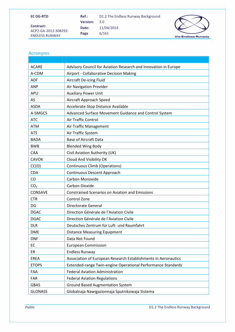
Acronyms ACARE Advisory Council for Aviation Research and Innovation in Europe A-CDM Airport - Collaborative Decision Making ADF Aircraft De-icing Fluid ANP Air Navigation Provider APU Auxiliary Power Unit AS Aircraft Approach Speed ASDA Accelerate-Stop Distance Available A-SMGCS Advanced Surface Movement Guidance and Control System ATC Air Traffic Control ATM Air Traffic Management ATS Air Traffic System BADA Base of Aircraft Data BWB Blended Wing Body CAA Civil Aviation Authority (UK) CAVOK Cloud And Visibility OK CC(O) Continuous Climb (Operations) CDA Continuous Descent Approach CO Carbon Monoxide CO2 Carbon Dioxide CONSAVE Constrained Scenarios on Aviation and Emissions CTR Control Zone DG Directorate General DGAC Direction Générale de l’Aviation Civile DGAC Direction Générale de l’Aviation Civile DLR Deutsches Zentrum für Luft- und Raumfahrt DME Distance Measuring Equipment DNF Data Not Found EC European Commission ER Endless Runway EREA Association of European Research Establishments in Aeronautics ETOPS Extended-range Twin-engine Operational Performance Standards FAA Federal Aviation Administration FAR Federal Aviation Regulations GBAS Ground Based Augmentation System GLONASS Globalnaja Nawigazionnaja Sputnikowaja Sistema
EC DG-RTD Contract: ACP2-GA-2012-308292- ENDLESS RUNWAY
Ref.: D1.2 The Endless Runway Background Version: 3.0
Date: 11/04/2014 Page 7/161
Public
D1.2 The Endless Runway Background
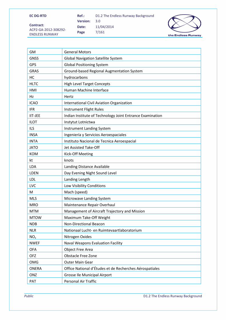
GM General Motors GNSS Global Navigation Satellite System GPS Global Positioning System GRAS Ground-based Regional Augmentation System HC hydrocarbons HLTC High Level Target Concepts HMI Human Machine Interface Hz Hertz ICAO International Civil Aviation Organization IFR Instrument Flight Rules IIT-JEE Indian Institute of Technology Joint Entrance Examination ILOT Instytut Lotnictwa ILS Instrument Landing System INSA Ingeniería y Servicios Aeroespaciales INTA Instituto Nacional de Tecnica Aeroespacial JATO Jet Assisted Take-Off KOM Kick-Off Meeting kt knots LDA Landing Distance Available LDEN Day Evening Night Sound Level LDL Landing Length LVC Low Visibility Conditions M Mach (speed) MLS Microwave Landing System MRO Maintenance Repair Overhaul MTM Management of Aircraft Trajectory and Mission MTOW Maximum Take-Off Weight NDB Non-Directional Beacon NLR Nationaal Lucht- en Ruimtevaartlaboratorium NOx Nitrogen Oxides NWEF Naval Weapons Evaluation Facility OFA Object Free Area OFZ Obstacle Free Zone OMG Outer Main Gear ONERA Office National d’Études et de Recherches Aérospatiales ONZ Grosse Ile Municipal Airport PAT Personal Air Traffic
EC DG-RTD Contract: ACP2-GA-2012-308292- ENDLESS RUNWAY
Ref.: D1.2 The Endless Runway Background Version: 3.0
Date: 11/04/2014 Page 8/161
Public
D1.2 The Endless Runway Background
PBN Performance Based Navigation PM Particulate Matter QFU Aviation Q-code for Magnetic Heading of a Runway RESA Runway End Safety Area RFID Radio-Frequency Identification RFL Requested Flight Level / Required Field Length RNAV Radar Navigation RNP Required Navigation Performance RSA Runway Safety Area RVR Runway Visual Range RW Runway SBAS Satellite Based Augmentation System SEL Sound Exposure Level SESAR Single European Sky ATM Research SID Standard Instrument Departure SMAN Surface Manager SOx Sulphur Oxides SRA Strategic Research Agenda STAC Service Technique de l’Aviation Civile STAR Standard Arrival Routes SWIM System Wide Information Management SWY Stopway TMA Terminal Manoeuvring Area TOD Top Of Descent TODA Take-Off Distance Available TOL Take-Off Length TOR Take-Off Run TORA Take-Off Run Available UAS Unmanned Aircraft System UK United Kingdom US United States USAF United States Air Force USN United States Navy VFR Visual Flight Rules VOC Volatile Organic Compounds VOR VHF Omnidirectional Range WS Wing Span
EC DG-RTD Contract: ACP2-GA-2012-308292- ENDLESS RUNWAY
Ref.: D1.2 The Endless Runway Background Version: 3.0
Date: 11/04/2014 Page 9/161
Public
D1.2 The Endless Runway Background
Definitions
Inner transitional surface
The inner transitional surface is similar to the transitional surface but closer to the runway. Its limits comprise
on one hand, an upper edge located in the plane of the inner horizontal surface and, on the other hand, a
lower edge beginning at the end of the inner approach surface and extending down the side of the inner
approach surface to the inner edge of that surface, from there along the strip parallel to the runway centre
line to the inner edge of the balked landing surface and from there up the side of the balked landing surface to
the point where the side intersects the inner horizontal surface.
The inner approach surface is defined as a rectangular portion of the approach surface immediately preceding
the threshold. Its limits comprise:
• An inner edge coincident with the location of the inner edge of the approach surface but of its own
specified length.
• Two sides originating at the ends of the inner edge and extending parallel to the vertical plane
containing the centre line of the runway.
• An outer edge parallel to the inner edge.
Approach surface
The approach surface consists of an inclined plane or combination of planes preceding the threshold. The
elevation of the inner edge shall be equal to the elevation of the mid-point of the threshold. Its slope shall be
measured in the vertical plane containing the centre line of the runway and shall continue containing the
centre line of any lateral offset or curved ground track. Its limits comprise:
• An inner edge of specified length, horizontal and perpendicular to the extended centre line of the
runway and located at a specified distance before the threshold.
• Two sides originating at the ends of the inner edge and diverging uniformly at a specified rate from
the extended centre line of the runway.
• An outer edge parallel to the inner edge.
• The above surfaces shall be varied when lateral offset, offset or curved approaches are utilized,
specifically, two sides originating at the ends of the inner edge and diverging uniformly at a specified
rate from the extended centre line of the lateral offset, offset or curved ground track.
Balked landing surface
The balked landing surface consists of an inclined plane located at a specified distance after the threshold,
extending between the inner transitional surface. Its elevation shall be equal to the elevation of the runway
centre line at the location of the inner edge. Its slope shall be measured in the vertical plane containing the
centre line of the runway. Its limits comprise:
EC DG-RTD Contract: ACP2-GA-2012-308292- ENDLESS RUNWAY
Ref.: D1.2 The Endless Runway Background Version: 3.0
Date: 11/04/2014 Page 10/161
Public
D1.2 The Endless Runway Background
• An inner edge horizontal and perpendicular to the centre line of the runway and located at a specified
distance after the threshold.
• Two sides originating at the ends of the inner edge and diverging uniformly at a specified rate from
the vertical plane containing the centre line of the runway.
• An outer edge parallel to the inner edge and located in the plane of the inner horizontal surface.
Conical surface
The conical surface is defined as a surface sloping upwards and outwards from the periphery of the inner
horizontal surface. The limits of the conical surface comprise on one hand, a lower edge coincident with the
periphery of the inner horizontal surface and, on the other hand, an upper edge located at a specific height
above the inner horizontal surface. Its slope shall be measured in a vertical plane perpendicular to the
periphery of the inner horizontal surface.
Inner horizontal surface
The inner horizontal surface is located in a horizontal plane above an aerodrome and its environs. Its radius
shall be measured from a reference point or points established for such purpose. Its height shall be measured
above an elevation datum established for such purpose.
Take-off climb surface
The take-off climb surface is an inclined plane or other specified surface beyond the end of a runway or
clearway. Its elevation shall be equal to the highest point on the extended runway centre line between the end
of the runway and the inner edge, except that when a clearway is provided the elevation shall be equal to the
highest point on the ground on the centre line of the clearway. In the case of a straight take-off flight path, the
slope of the take-off climb surface shall be measured in the vertical plane containing the centre line of the
runway. Regarding a take-off path involving a turn, the take-off climb surface shall be a complex surface
containing the horizontal normals to its centre line, and the slope of the centre line shall be the same as that
for a straight take-off flight path. Its limits comprise:
• An inner edge horizontal and perpendicular to the centre line of the runway and located either at a
specified distance beyond the end of the runway or at the end of the clearway when such is provided
and its length exceeds the specified distance.
• Two sides originating at the ends of the inner edge, diverging uniformly at a specified rate from the
take-off track to a specified final width and continuing thereafter at that width for the remainder of
the length of the take-off climb surface.
• An outer edge horizontal and perpendicular to the specified take-off track.
Clearway A clearway (CWY) is a rectangular area, whose width must be at least 150 m (according to ICAO recommendations), beginning at the end of the runway and centred on the runway’s extended centreline, over which an airplane can make the initial portion of its flight on take-off.

EC DG-RTD Contract: ACP2-GA-2012-308292- ENDLESS RUNWAY
Ref.: D1.2 The Endless Runway Background Version: 3.0
Date: 11/04/2014 Page 11/161
Public
D1.2 The Endless Runway Background
Stopway A stopway (SWY) is a rectangular area, at least as wide as the runway, beginning at the end of it and centred on its extended centreline, which has been prepared as a suitable area where an aircraft can be stopped in the case of an aborted take-off without suffering structural damage. TORA The TORA (Take-Off Run Available) is the length of runway declared available and suitable for the ground run of an aircraft taking off. TODA The TODA (Take-Off Distance Available) is the length of the take-off run available (TORA) plus the length of the existing clearway, if any. The TODA is greater than the maximum distance between TOD1 and TOD2, with:
• TOD1 (Figure 1): 115% of the distance needed by the aircraft to reach a height of 35 ft (10.7m) with all engines assumed available throughout.
Figure 1 TOD1 calculation
• TOD2 (Figure 2): distance, from the start of the take-off run, needed for the aircraft to attain an altitude of 35 ft (10.7 m) if it continues to take-off when one engine fails.
Figure 2 TOD2 calculation
ASDA The ASDA (Accelerate-Stop Distance Available) is the length of the take-off run available (TORA) plus the length of the existing stopway, if any. LDA The LDA (Landing Distance Available) is the length of the runway declared available and suitable for the ground run of an aircraft landing. For turbine-powered aircraft, the aircraft must be able to stop within at most 60% of the landing length of the runway (LDA). It is assumed that the aircraft flies over the threshold of the runway at a height of 50 ft (15 m).
All engines
All engines One engine failed
TOD2
TOD1
EC DG-RTD Contract: ACP2-GA-2012-308292- ENDLESS RUNWAY
Ref.: D1.2 The Endless Runway Background Version: 3.0
Date: 11/04/2014 Page 12/161
Public
D1.2 The Endless Runway Background
1 Introduction The Endless Runway project aims at building a concept of runway of circular shape that enables aircraft to
always operate with headwind at landing and take-off. The runway is called “endless“, as runway overruns
cannot occur since the runway has no end. The airport terminals with all aircraft, passenger, baggage, and
cargo facilities are located within the circle, making the airport more compact than a conventional airport of
equal dimensions.
Wind direction, wind speed, and visibility conditions are the major factors in the decision of air traffic control
to use a certain runway configuration. Tailwind and crosswind components determine whether runways can
be used or not, and low visibility limits the use of dependent runways. Imposed direction of the runways
results in a dependency to the wind direction, and to the fact that aircraft have to use the same approach
path, resulting in the need for wake turbulence separation. The Endless Runway operates a concept consisting
of a circular runway that will allow take-off in any direction and landing from any direction, thus making the
airport operations independent of wind direction and speed.
In this document, elements concerned with the design and operation of the Endless Runway are explored.
Chapter 2 explores earlier work on circular runways. Theoretical work is analysed in detail and experiences
from live trials are noted down. Chapter 3 then analyses which other alternatives exist to the current straight
runways, which mostly have the same motivation for their construction: independency from the wind
direction.
Chapters 4 to 7 describe specific elements with regard to current and future operations. Chapter 4 gives an
overview on visions of the air transport system of the future. Chapter 5 focuses on runway and airport design,
including capacity, environmental and accessibility considerations, and chapter 6 gives details of relevant Air
Traffic Management (ATM) procedures, specifically for landing and take-off. Chapter 7 then introduces some
considerations on aircraft candidates to operations on circular tracks.
Finally, chapter Appendix C provides an overview of relevant current regulations on the construction and
operations of runways.

EC DG-RTD Contract: ACP2-GA-2012-308292- ENDLESS RUNWAY
Ref.: D1.2 The Endless Runway Background Version: 3.0
Date: 11/04/2014 Page 13/161
Public
D1.2 The Endless Runway Background
2 Background on circular runways The idea of a circular runway is not new: since the early days of aviation, people discuss and experiment new
ways of take-off and landing, including the circular runway. This chapter provides an overview of earlier work
on the subject.
2.1 History of the concept An analysis of early work done on circular runways is conducted based on initial research performed during the
project preparation [1], on U.S. Navy study [18], [19], on expired patents on circular runways [11], [12], [13],
[14], [17], and related scientific press articles [1] to [10]. A summary of the evolution of the concept from 1919
to nowadays is provided, mostly based on articles [1], [3], [4], [5], [6], [7], [8], [9], [10] and on the research
done during writing of the project proposal [1]. This section will give a high level overview of concepts; the
following sections will describe the patents and ideas in more detail.
2.1.1 Popular Science Monthly and Backus concepts (1919-1921)
In 1919, a circular track appears for the first time
in the press, in the “Popular Science Monthly”
newspaper [1]. The problem in these days was to
find a way to take off and land in or near big cities
such as New York with skyscrapers of different
heights. An idea was found to construct a circular
runway on top of the skyscrapers, without cutting
off light and air from the streets below. A banked
circular track, made of iron, supported by several
buildings, seemed to be a solution to solve this
accessibility problem. Aircraft would circulate
clockwise and always take off and land in
headwind conditions following a spiral trajectory.
A special shifting signal would distinctly indicate
the area which is parallel to the wind and opposite
to the circling plane direction. Aircraft would move
on the roof of one of the buildings, where the
track would continue inside with a lift.
Figure 3 Circular track in Manhattan, 1919
In 1921, a first circular runway is patented by P.J. Backus [46]. He proposes a flat and small circular trackway,
which was adapted to light aircraft of that time.
2.1.2 Winans and Tempest concepts (1955-1957)
In 1955, the idea of a circular runway emerged again [3]. Inspired by tethered models and by a stuntman
named Jean Roche who had demonstrated circular take-off in 1938, Dr. John Gibson Winans, a professor of

EC DG-RTD Contract: ACP2-GA-2012-308292- ENDLESS RUNWAY
Ref.: D1.2 The Endless Runway Background Version: 3.0
Date: 11/04/2014 Page 14/161
Public
D1.2 The Endless Runway Background
physics at the University of Wisconsin and passionate about aviation, foresaw the advantages of such a
concept: aircraft roll-out and overrun would be avoided thanks to the “infinite” length of a circular runway.
This advantage was considered especially valuable in emergency situation (engine failure or iced-up wings),
during landing and take-off.
In 1957, a refined design of the circular runway was proposed by Sir H. Tempest [4]. The problem at hand was
the future evolution of jet aircraft whose speed was expected to increase more and more, causing straight
runways to be longer and longer. Subsequent problem was the size of major airports. Indeed, their growth was
limited by the land available, the cost of the land, and the necessary expenses for building and maintaining
them. Finding new free sites near major cities or extending aerodromes raised the same concerns. Such
constraints lead to the circular runway concept (see Figure 4): with a 914 meters diameter, the runway would
measure 2,870 meters and the surface of such an airport would be of about 0.66 km2 (to be compared with
the 12 km2 from London Airport at the time). Thanks to the “endless” runway, the run on the runway could be
extended, longer than its actual length, accommodating aircraft take-off and landing runs as long as needed to
reach take-off speed or full stop.
Figure 4 Perspective view of the circular runway airport, 1957
Figure 5 Section view of the circular runway, 1957
The concept foresaw a steeply banked runway to accommodate aircraft even at very high speed (see Figure 5).
The vertical banking on the outer edge was proposed for safety reason, to prevent runway excursion. A
specific approach procedure was proposed: aircraft arriving over the airport would lose height in a spiral glide

EC DG-RTD Contract: ACP2-GA-2012-308292- ENDLESS RUNWAY
Ref.: D1.2 The Endless Runway Background Version: 3.0
Date: 11/04/2014 Page 15/161
Public
D1.2 The Endless Runway Background
directly over the runway throughout the landing, preventing landing undershoot or overshoot. The visibility of
the runway and the proximity of the control tower during the approach (457 meters) were seen as useful
assets for the pilot especially in bad weather condition.
2.1.3 U.S. Navy concept (1960-1965)
In 1960, Navy Pilot Lt. Cmdr. James R. Conrey from the U.S. Navy seriously thought of the circular runway,
having in mind the ability to land in any wind condition. He put his results on paper and won a U.S. patent [11].
After his death in a plane accident, a project dedicated to the circular runway was launched by the U.S. Navy.
In 1965, Officer Commander Lloyd Smith published a technical report on circular runways [18], which
theoretical results are described in detail in paragraph 2.3.1.
The airport design (see Figure 6) consists of a main runway in the form of a banked track constituting the
perimeter of the airport. At the centre of the circle is the control tower (N) housing radar and navigation aids.
It is surrounded by an open parking and gardens (M), themselves encircled by a ring-shaped passenger
terminal building (L). The entire outer wall of the terminal faces the runway. It provides a maximum of parking
and loading positions for planes (K). The parking and loading area is connected with the runway by taxiways for
departing aircraft (I) and high speed turn-off ramps for arriving aircraft (H), 24.4 meters wide and arranged like
spokes on a wheel. Finally, a roadway (J) passes under the airport for passengers’ access to the terminal
building.
Figure 6 Circular runway airport design,US Navy report
The circular runway, to accommodate aircraft with broad speed ranges (e.g. up to 151 kt), would need to be 98
meters wide. It would be about 9,400 meters long, which corresponds to a diameter of about 3,000 meters.
N
A – 1600 meters radius B – 1582 meters radius C – 1567 meters radius D – 1543 meters radius E – 1519 meters radius F – 1509 meters radius G – Radial markers 305 meters apart H – High speed turn-off I – Taxi out for departure J – Auto access (under runway and ramp) K – Aircraft parking and loading ramp L – Airport terminal building M – Open park and gardens N – Control tower radar and navigation aids

EC DG-RTD Contract: ACP2-GA-2012-308292- ENDLESS RUNWAY
Ref.: D1.2 The Endless Runway Background Version: 3.0
Date: 11/04/2014 Page 16/161
Public
D1.2 The Endless Runway Background
In operation, three or more aircraft could take off simultaneously, which would leave more than 3,050 meters
separation between each plane. In low wind conditions, aircraft could then depart in three different directions.
For landing, incoming planes could land at a high frequency on one predetermined touchdown point.
In an article from the NewScientist Magazine [10], the possibility to have an even bigger runway (18,300
meters in circumference that is to say 5,800 meters diameter) is mentioned, which would allow six aircraft to
operate on the runway simultaneously. Each aircraft would still have about 3,050 meters margin for take-off,
as on conventional straight runways.
Actually, the wheel-shaped airport was foreseen for both civilian and military use, with a diameter ranging
from 1,200 to 6,100 meters for the largest international airports. It must be noted there that, below a certain
radius, the g force becomes so large that more lift is needed to take off, which requires a higher speed, which
again increases the g force.
The dilution of the cross-wind problem, the gain in land use compared to a comparable conventional airport
(one-third saved space), and the unlimited runway available for take-off and landing were already known from
previous circular runway designers. Even more advantages were foreseen by the U.S. Navy [7]. From the safety
side, one can mention the inherent stable tracking feature, the maximum runway access for the crash crews,
and the possibility to make flameout and dead-stick1 approaches. Unlimited flexibility in approach and
departure corridors, minimum required taxi distance, rapid aircraft departures and arrivals, optimum low
visibility procedures would increase airport capacity. Considering efficiency, the optimum control tower
position (unobstructed view of every portion of the runway), installation of navigation aids in the control
tower, and passenger access to and from aircraft from the centre building complex were other assets from this
design. Compactness derived in the building complex would have a positive effect on land use, cost, and
efficiency. From the environmental perspective, noise abatement procedures could be defined thanks to the
runway’s lateral geometry. For military purposes, fragmentation by enemies would require a plurality of well-
placed craters before making the runway unusable.
Interest to the concept was even expressed by aviation authorities in Sydney, Australia, in 1965 [6].
2.1.4 Final thoughts
One of the reasons why the circular runway remained at experimental level was probably the cost of such a
runway and the need for new procedures and techniques. Construction costs would be higher than for
capacity-equivalent conventional runways because of the requirement for precise banking of the runway and
for larger runway width (98 meters instead of maximum 60 meters) and length (10,000 meters versus
maximum 4,000 meters). Another reason was that the design studies of these concepts study did not involve
1 A flameout refers to the failure of a jet engine caused by the extinction of the flame in the combustion chamber. A deadstick landing is a type of forced landing when an aircraft loses all of its propulsive power and is forced to land (Wikipedia)
EC DG-RTD Contract: ACP2-GA-2012-308292- ENDLESS RUNWAY
Ref.: D1.2 The Endless Runway Background Version: 3.0
Date: 11/04/2014 Page 17/161
Public
D1.2 The Endless Runway Background
devising new landing techniques and procedures, which are necessary for implementation in the air traffic
environment.
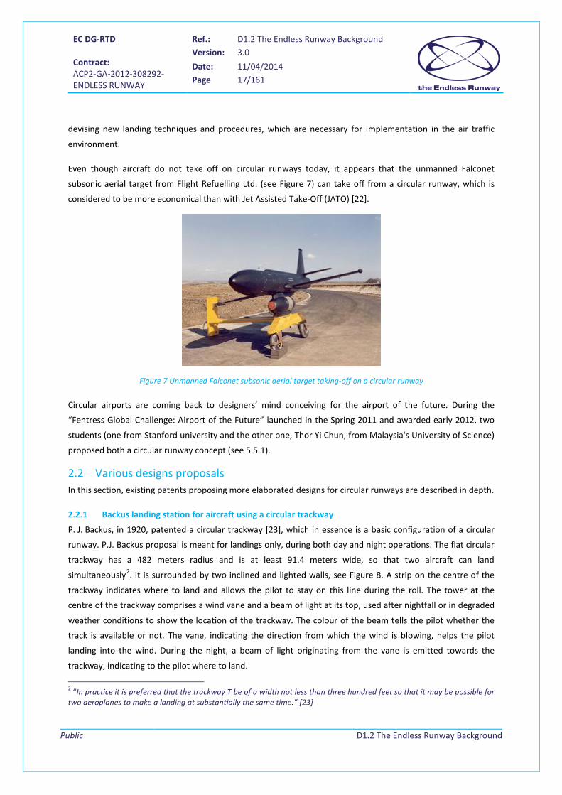
Even though aircraft do not take off on circular runways today, it appears that the unmanned Falconet
subsonic aerial target from Flight Refuelling Ltd. (see Figure 7) can take off from a circular runway, which is
considered to be more economical than with Jet Assisted Take-Off (JATO) [22].
Figure 7 Unmanned Falconet subsonic aerial target taking-off on a circular runway
Circular airports are coming back to designers’ mind conceiving for the airport of the future. During the
“Fentress Global Challenge: Airport of the Future” launched in the Spring 2011 and awarded early 2012, two
students (one from Stanford university and the other one, Thor Yi Chun, from Malaysia's University of Science)
proposed both a circular runway concept (see 5.5.1).
2.2 Various designs proposals In this section, existing patents proposing more elaborated designs for circular runways are described in depth.
2.2.1 Backus landing station for aircraft using a circular trackway
P. J. Backus, in 1920, patented a circular trackway [23], which in essence is a basic configuration of a circular
runway. P.J. Backus proposal is meant for landings only, during both day and night operations. The flat circular
trackway has a 482 meters radius and is at least 91.4 meters wide, so that two aircraft can land
simultaneously2. It is surrounded by two inclined and lighted walls, see Figure 8. A strip on the centre of the
trackway indicates where to land and allows the pilot to stay on this line during the roll. The tower at the
centre of the trackway comprises a wind vane and a beam of light at its top, used after nightfall or in degraded
weather conditions to show the location of the trackway. The colour of the beam tells the pilot whether the
track is available or not. The vane, indicating the direction from which the wind is blowing, helps the pilot
landing into the wind. During the night, a beam of light originating from the vane is emitted towards the
trackway, indicating to the pilot where to land.
2 “In practice it is preferred that the trackway T be of a width not less than three hundred feet so that it may be possible for two aeroplanes to make a landing at substantially the same time.” [23]
EC DG-RTD Contract: ACP2-GA-2012-308292- ENDLESS RUNWAY
Ref.: D1.2 The Endless Runway Background Version: 3.0
Date: 11/04/2014 Page 18/161
Public
D1.2 The Endless Runway Background
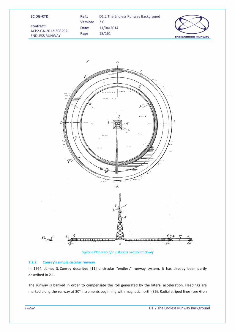
Figure 8 Plan view of P.J. Backus circular trackway
2.2.2 Conrey’s simple circular runway
In 1964, James S. Conrey describes [11] a circular “endless” runway system. It has already been partly
described in 2.1.
The runway is banked in order to compensate the roll generated by the lateral acceleration. Headings are
marked along the runway at 30° increments beginning with magnetic north (36). Radial striped lines (see G on
EC DG-RTD Contract: ACP2-GA-2012-308292- ENDLESS RUNWAY
Ref.: D1.2 The Endless Runway Background Version: 3.0
Date: 11/04/2014 Page 19/161
Public
D1.2 The Endless Runway Background
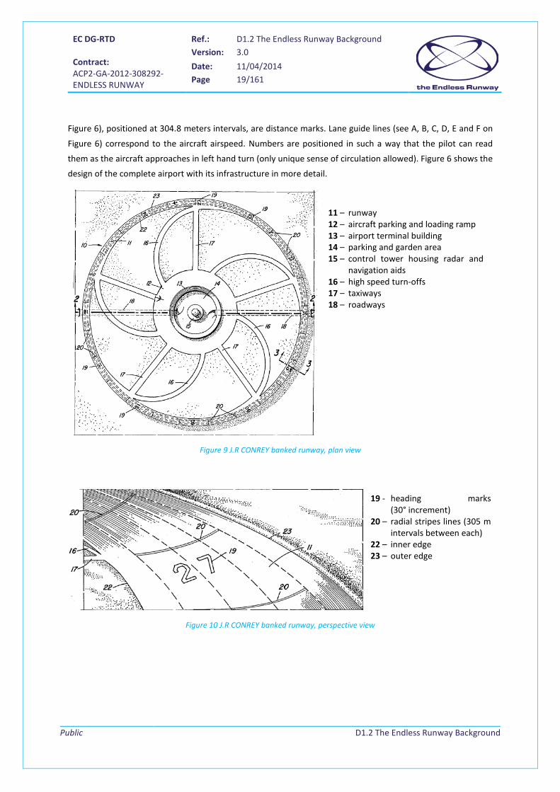
Figure 6), positioned at 304.8 meters intervals, are distance marks. Lane guide lines (see A, B, C, D, E and F on
Figure 6) correspond to the aircraft airspeed. Numbers are positioned in such a way that the pilot can read
them as the aircraft approaches in left hand turn (only unique sense of circulation allowed). Figure 6 shows the
design of the complete airport with its infrastructure in more detail.
Figure 9 J.R CONREY banked runway, plan view
Figure 10 J.R CONREY banked runway, perspective view
19 - heading marks (30° increment)
20 – radial stripes lines (305 m intervals between each)
22 – inner edge 23 – outer edge
11 – runway 12 – aircraft parking and loading ramp 13 – airport terminal building 14 – parking and garden area 15 – control tower housing radar and
navigation aids 16 – high speed turn-offs 17 – taxiways 18 – roadways

EC DG-RTD Contract: ACP2-GA-2012-308292- ENDLESS RUNWAY
Ref.: D1.2 The Endless Runway Background Version: 3.0
Date: 11/04/2014 Page 20/161
Public
D1.2 The Endless Runway Background
Figure 11 J.R CONREY banked runway, enlarged sectional view
The infrastructure involves a network of taxiways aimed at connecting the airport building at the centre of the
circle with the runway. The arrival taxiways (high speed exits) are curved while the departure taxiways are
straight lines. High speed exits are banked at 1.5° to the left in the left hand motion. They are approximately
24.4 meters wide.
2.2.3 Bary’s circular runway
In 1965, Woldmar Bary patented a Closed track airport [12] which only brings few updates to the previous one:
it describes take-offs and landings in headwind conditions using a sloped runway.
Figure 12 A. Woldemar Bary's closed track airport plan and sectional views
11 – Ring area (182 hectares) 12 – complex of buildings (control tower, hangars, baggage storage and freight storage facilities, waiting rooms for passengers, etc.) and cars parking 15 – circular runway (457 m to 914 m radius, 61 m to 91 m width, bank angle increasing from 0,15 to 0,2 m per m) 16 – hard surface (paving) 18 – outer peripheral portion of the runway (18 m height and 30° bank angle) 20 – aircraft 22 – apron (emergency surface) 24 – ramp (for emergency only, gradual slope) 31, 32 – tunnels for pedestrian, cars; trucks, buses, other small vehicles 34 – roads 36 – circles at the end of the roads for turnarounds 41-48 – sections of the runway identified by different colour paving 51-58 – Signs identifying each runway sections 62, 64 – runway circles marking

EC DG-RTD Contract: ACP2-GA-2012-308292- ENDLESS RUNWAY
Ref.: D1.2 The Endless Runway Background Version: 3.0
Date: 11/04/2014 Page 21/161
Public
D1.2 The Endless Runway Background
The “ring-track” might be a circle, an ellipse, or an oval, the circular shape being the preferred one, as depicted
on Figure 12. A particularity of this patent is that occasional and emergency passage of extra-large vehicles
(including aircraft) is enabled through a tractor towing over the track banking (see legend 24 in Figure 12).
Only one aircraft at a time can use the runway.
For landing, the aircraft is first guided towards the runway on a straight path with a kind of ancient ILS, a
conventional blind landing electronic apparatus. Then the pilot circles in the air over the track and makes
appropriate use of rudder and ailerons to give the aircraft the right bank angle before landing. He lands at the
slowest possible speed, facing the wind, on the appropriate runway section and radial as instructed by ATC. He
then rolls the aircraft following a spiral course towards the inside of the runway, circling as many times as
needed, decreasing speed with sole use of wing flaps and regular wheel brakes. Flaps control is also used to
obtain the required anti-centrifugal force. Radar guidance with an on-board display is used for landing roll.
Take-off operation starts with the aircraft entering the runway at any convenient point from the inside ring
area. Radar guidance with an on-board display is used for take-off roll. The pilot accelerates the aircraft, rolling
for as many track loops as necessary to reach the decision speed. He then manages to reach the appropriate
runway section and radial as instructed by ATC, where he faces the wind and from where he can accelerate
until Vr and takes off.
The advantages of the circular runway foreseen by W. A. Bary are the reduction of airport land-use, the
proximity to the area to be served, the longest life of aircraft systems such as engines and wheels, and a
reduction of the noise print of the airport, due to slower aircraft accelerations and decelerations. Added value
of the “infinite” runway is mentioned for high-altitudes airports, where take-offs are longer and landings
faster.
2.2.4 Bary’s circular runways with three straight segments
In 1967, Woldemar A. Bary designed a Closed track airport with straight runways for instrument landing and
take-off [14] which is proposed as an improvement of his previous patent 3173634 (see 2.2.3). It is composed
of several straight runways included as chords of arcs of the circular shaped track (which can be a circle, as on
Figure 13, an ellipse or any other variation). These chords are to be used at the end of the take-off and at the
beginning of the landing, in order to be able to make straight instrument landings. Moreover, transition from a
straight to a curved run will be easier for landing than adopting the proper banking in flight. Indeed, the pilot
will have a few seconds, depending on the aircraft speed, to properly find the exact point of landing. Similar
reasoning applies for take-off.

EC DG-RTD Contract: ACP2-GA-2012-308292- ENDLESS RUNWAY
Ref.: D1.2 The Endless Runway Background Version: 3.0
Date: 11/04/2014 Page 22/161
Public
D1.2 The Endless Runway Background
Figure 13 Closed track airport with straight runways for instrument landing and take-off plan view
The three chordal tracks are located symmetrically on a triangular pattern in accordance with prevailing winds
or other local requirements. Their length is such that 𝐿𝑐ℎ𝑜𝑟𝑑𝑠 ≤ √2𝑅.
Figure 14 Closed track airport with straight runways for instrument landing and take-off enlarged sectional views
10 – airport (260 hectares) 12 – curved banked and paved closed track airstrip (bank from 0° to 30° corresponding to a 50 feet outwards elevation, width 250 feet, outside diameter 5000 feet) 18 – ramp for aircraft towing along the ground 21-23 – straight and level chordal tracks (2000 feet long and 100 to 200 feet wide) 25 – arcuate section of the inner ring track 34 – row of concealed radar reflectors 40, 42, 44 – course of a landing aircraft 50 – aircraft in approach 60 – inner ring 61-63 – pavilions of debarkation 65 – aircraft parked on pavillons 61, 62 and 63 67 – hangars 69 – roadways 70 – tunnel under the track 75 – control tower Around 75 – 3 parking lots 72 – tangent course
16 – hump 30 – descending aircraft (maximum 7° slope) 45°

EC DG-RTD Contract: ACP2-GA-2012-308292- ENDLESS RUNWAY
Ref.: D1.2 The Endless Runway Background Version: 3.0
Date: 11/04/2014 Page 23/161
Public
D1.2 The Endless Runway Background
As depicted on Figure 14, the bank angle follows a parabolic shape of 61 meters (200 ft.) and becomes flat on
its inner part for 15 meters (50 ft.). Aircraft can be towed over the hump in emergency situations, thanks to
the slow slope of the dedicated ramp.
The track’s bank angle, also called here superelevation3 S, is given by the following formula borrowed from
highway engineering formulas (see [15] and [16]):
𝑆 =𝑉2
𝑔 ∙ 𝑅− 𝐹
where: V = design speed (e. g. 65 m∙s-1) g = gravity (9.81 m∙s-2) R = radius of the track curve F = side friction coefficient (e. g. 0.12)
For aircraft characteristics in the 60’s, this meant that S was equal to 17.5 %.
During landing, the aircraft approaches the airport on a straight course with an angle of descent lower than 7°.
The pilot follows the instructions from the control tower and flies towards the assigned chordal track, which
mainly depends on the wind. Note that the risk of overshooting the runway landing point is taken into account
through a margin of length given to the straight chordal track.
For departure, the aircraft leaves its parking area and enters either the curved track or the straight strip at the
nearest to the pavilion point, in order to lower taxiing time. Then it accelerates slowly on the endless track,
doing as many loops as necessary, until it reaches its decision speed. It then takes off into the wind, either
along a tangent course or from a straight track.
Again, as in the previous patent, during the roll on the circular part of the runway, flaps, rudder, and aileron
are used to compensate centrifugal forces.
2.2.5 Bary’s circular runway with straight inlet runways
Bary’s concept of endless runway is further explored in a closed track airport with inlet runways for straight
instrument landings [13]. The previous patents suffered from the fact that the straight portion of the runway
was limited in length and that there was some constraint on descent rate due to the height of the hump, which
was considered an obstacle with a safety risks. The new patent can be applied to partially closed tracks.
In this new concept, straight level portions of runways are added outside the ring and join a flat portion of the
circular track. A small number (1, 2 or 3) of touchdown points are allowed for landing, each associated with its
own ILS.
3 This lateral slope of the track is known in civil engineering for highways as the “superelevation”.

EC DG-RTD Contract: ACP2-GA-2012-308292- ENDLESS RUNWAY
Ref.: D1.2 The Endless Runway Background Version: 3.0
Date: 11/04/2014 Page 24/161
Public
D1.2 The Endless Runway Background
Figure 15 Closed track airport with three tangential runways for straight instrument landings plan view
Figure 16 Closed track airport with three tangential runways for straight instrument landings plan view
version 2
10, 10a, 10b, 10c, 10d – airport 12, 12a, 12b, 12c, 12d – land track 16 – curved runway (bank from 0° to 30° corresponding to a 40 feet outwards elevation) 21-23, 21a-22a, 21b, 21c-23c, 21d-22d – tangential runways 26-28, 26a-27a, 26b, 26c-28c, 26d-27d – curved sections (radius: 2500 feet) 31-33, 31a-32a, 31b, 31c-33c, 31d-32d – straight sections joining curved sections, 1000 feet in length (transition part: the bank of the track changes progressively along its length in accordance with conventional railroads and highway engineering practice) 50, 50a, 50b, 50c, 50d – control tower on top of the administration building 52, 52a, 52b, 52c, 52d – debarkation pavilions 54, 54a, 54b, 54c, 54d –roadway 56, 56a, 56b, 56c, 56d - parking area 58, 58a, 58b, 58c, 58d – hangars 60, 60a, 60b, 60c, 60d – connecting roadways 63-64, 63c-64c – roads 66, 66a, 66b, 66c, 66d – tunnel 70 - start of a straight runway portion 74 – possible aircraft path 76 – unpaved area
Upon arrival, aircraft land on one of the straight inlet (depending on e.g. wind considerations) and roll up to
the curved and banked runway portion where they slow down until they reach their taxiing speed and head
towards the inner part of the circle. W.A. Bary mentions that landing into the wind is not so important any
more with the circular runway as the ground run can be as long as needed on the infinite track.
For departures, the take-off run is made along a curved section. Once decision speed is reached, the aircraft
can take off, either on a curved or on a straight section, at a point into the wind, if desired. Indeed, as take-off
is not carried out using instruments, taking-off from a straight section is not necessary.
EC DG-RTD Contract: ACP2-GA-2012-308292- ENDLESS RUNWAY
Ref.: D1.2 The Endless Runway Background Version: 3.0
Date: 11/04/2014 Page 25/161
Public
D1.2 The Endless Runway Background
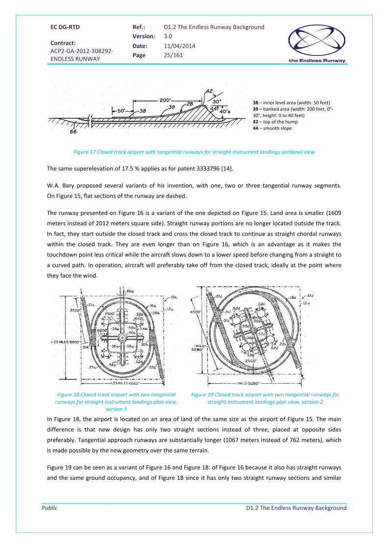
38 – inner level area (width: 50 feet) 39 – banked area (width: 200 feet, 0°-30°, height: 0 to 40 feet) 42 – top of the hump 44 – smooth slope
Figure 17 Closed track airport with tangential runways for straight instrument landings sectional view
The same superelevation of 17.5 % applies as for patent 3333796 [14].
W.A. Bary proposed several variants of his invention, with one, two or three tangential runway segments.
On Figure 15, flat sections of the runway are dashed.
The runway presented on Figure 16 is a variant of the one depicted on Figure 15. Land area is smaller (1609
meters instead of 2012 meters square side). Straight runway portions are no longer located outside the track.
In fact, they start outside the closed track and cross the closed track to continue as straight chordal runways
within the closed track. They are even longer than on Figure 16, which is an advantage as it makes the
touchdown point less critical while the aircraft slows down to a lower speed before changing from a straight to
a curved path. In operation, aircraft will preferably take off from the closed track, ideally at the point where
they face the wind.
Figure 18 Closed track airport with two tangential
runways for straight instrument landings plan view, version 1
Figure 19 Closed track airport with two tangential runways for straight instrument landings plan view, version 2
In Figure 18, the airport is located on an area of land of the same size as the airport of Figure 15. The main
difference is that new design has only two straight sections instead of three, placed at opposite sides
preferably. Tangential approach runways are substantially longer (1067 meters instead of 762 meters), which
is made possible by the new geometry over the same terrain.
Figure 19 can be seen as a variant of Figure 16 and Figure 18: of Figure 16 because it also has straight runways
and the same ground occupancy, and of Figure 18 since it has only two straight runway sections and similar

EC DG-RTD Contract: ACP2-GA-2012-308292- ENDLESS RUNWAY
Ref.: D1.2 The Endless Runway Background Version: 3.0
Date: 11/04/2014 Page 26/161
Public
D1.2 The Endless Runway Background
terminal facilities placement. This new geometry allows the straight sections to be longer than in Figure 16, as
they can extend further outside the closed track.
Figure 20 Closed track airport with one tangential runway for straight instrument landings plan view
Figure 20 is similar to Figure 15 and Figure 18 except that it has only one approach runway. In this design, the
different shape of the track provides for a different arrangement of the pavilion and hangar complex.
2.2.6 Scelze’s coupled circular runways
In 1972, Robert Scelze describes [17] a couple of adjacent circular tracks oriented clockwise (for the runway)
and counter-clockwise (for the taxiway), with three straight segments in the middle of the circle. The author
aims at giving an endless length of runway for take-off and landing, preserving straight into the wind portions
of runway for critical part of these manoeuvers. He considers that if this invention was standardized for many
airports in the world, this would simplify pilots’ training since there would be a unique type of airport layout.
Of course, classical advantages from the circular runway are mentioned (reduced land use, improved airport
capacity, elimination of cross wind for landings and take-offs…).
Buildings, parking, storage, etc., are built on the area outside of circular stripe 6. On this airport, there is no
obstruction and the ground infrastructures are level, contrary to previous patents where the track is banked.
For departure, aircraft taxiing takes place on circular runway 9 in a counter clockwise direction. The
acceleration run for take-off starts on runway 10 in a clockwise direction and then continues turning onto one
of operational runways C, L or R. Control would be done by the pilots themselves, departing aircraft being able
to see approaching aircraft.
When landing, the pilot aligns the aircraft with the appropriate operational straight runways, using the
heading markings (see 12 on Figure 21), the circles (17) and bulls eye circle (19). The touchdown takes place
EC DG-RTD Contract: ACP2-GA-2012-308292- ENDLESS RUNWAY
Ref.: D1.2 The Endless Runway Background Version: 3.0
Date: 11/04/2014 Page 27/161
Public
D1.2 The Endless Runway Background
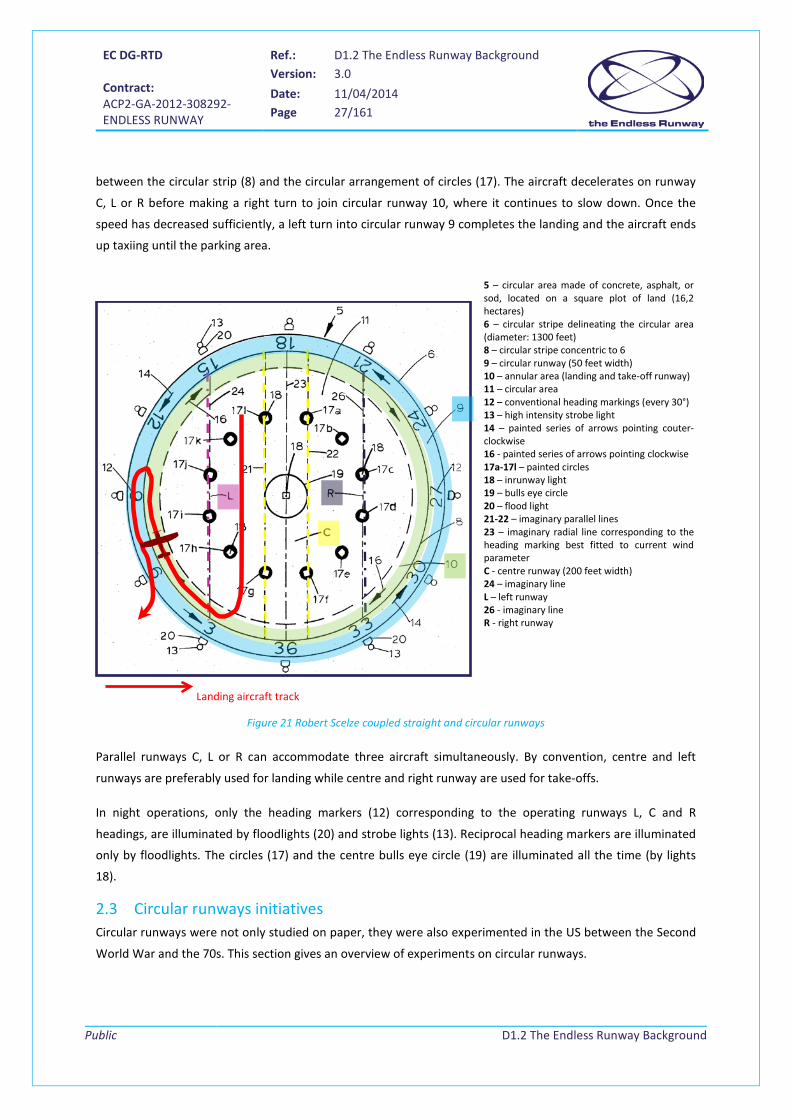
between the circular strip (8) and the circular arrangement of circles (17). The aircraft decelerates on runway
C, L or R before making a right turn to join circular runway 10, where it continues to slow down. Once the
speed has decreased sufficiently, a left turn into circular runway 9 completes the landing and the aircraft ends
up taxiing until the parking area.
Figure 21 Robert Scelze coupled straight and circular runways
Parallel runways C, L or R can accommodate three aircraft simultaneously. By convention, centre and left
runways are preferably used for landing while centre and right runway are used for take-offs.
In night operations, only the heading markers (12) corresponding to the operating runways L, C and R
headings, are illuminated by floodlights (20) and strobe lights (13). Reciprocal heading markers are illuminated
only by floodlights. The circles (17) and the centre bulls eye circle (19) are illuminated all the time (by lights
18).
2.3 Circular runways initiatives Circular runways were not only studied on paper, they were also experimented in the US between the Second
World War and the 70s. This section gives an overview of experiments on circular runways.
5 – circular area made of concrete, asphalt, or sod, located on a square plot of land (16,2 hectares) 6 – circular stripe delineating the circular area (diameter: 1300 feet) 8 – circular stripe concentric to 6 9 – circular runway (50 feet width) 10 – annular area (landing and take-off runway) 11 – circular area 12 – conventional heading markings (every 30°) 13 – high intensity strobe light 14 – painted series of arrows pointing couter-clockwise 16 - painted series of arrows pointing clockwise 17a-17l – painted circles 18 – inrunway light 19 – bulls eye circle 20 – flood light 21-22 – imaginary parallel lines 23 – imaginary radial line corresponding to the heading marking best fitted to current wind parameter C - centre runway (200 feet width) 24 – imaginary line L – left runway 26 - imaginary line R - right runway
Landing aircraft track

EC DG-RTD Contract: ACP2-GA-2012-308292- ENDLESS RUNWAY
Ref.: D1.2 The Endless Runway Background Version: 3.0
Date: 11/04/2014 Page 28/161
Public
D1.2 The Endless Runway Background
2.3.1 Take-off and landing live trials on circular runways
In 1938, circular flat take-off was demonstrated as a stunt by a certain Jean Roche in Riverdale airfield,
Maryland. A hub, a spindle, and a release gear were used [3].
During the Second World War, endless runways were used for training purposes to practice cross wind and
back wind landings. On the other hand, it was also possible to avoid crosswind by using an appropriate runway
segment. These airports were not circular, but rather consisted of "regular straight runways laid out in a
pattern where the end of one runway would connect with the next runway at about a 45 degrees angle" [21].
Circular flat take-off was first tested on ice the 21st of March 1955 on Lake Kegonsa, Wisconsin, with a light
aircraft, the Ercoupe [3].
Figure 22 Ercoupe aircraft used for circular take-off on frozen lake, 1955
This required special equipment: a spindle and a hub were attached to a steel barrel frozen into the ice and
guyed solidly. A double strand of woven nylon, 400’ long, led to a quick-release fixture under a wing of the
aircraft. Even though the aircraft left the ground after sweeping just part way round the circle, the first four
tries were failures, as the rope broke before a controlled release was made. Following take-off trials were
successful, but is has to be noted that landing was out of scope of this trial.
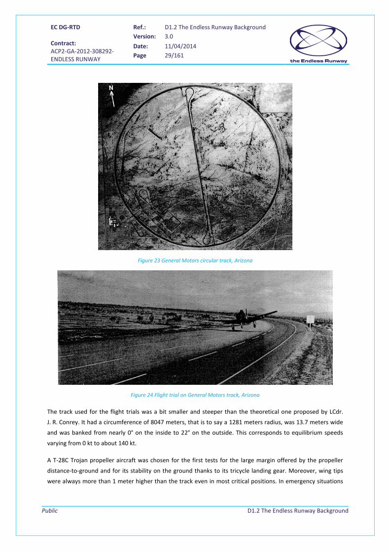
In 1964 and 1965, tests were undertaken at the General Motors Desert Proving Grounds track near Mesa,
Arizona, on a circular banked track, after an agreement between the NWEF (Naval Weapons Evaluation
Facility) and General Motors [19].
EC DG-RTD Contract: ACP2-GA-2012-308292- ENDLESS RUNWAY
Ref.: D1.2 The Endless Runway Background Version: 3.0
Date: 11/04/2014 Page 29/161
Public
D1.2 The Endless Runway Background
Figure 23 General Motors circular track, Arizona
Figure 24 Flight trial on General Motors track, Arizona
The track used for the flight trials was a bit smaller and steeper than the theoretical one proposed by LCdr.
J. R. Conrey. It had a circumference of 8047 meters, that is to say a 1281 meters radius, was 13.7 meters wide
and was banked from nearly 0° on the inside to 22° on the outside. This corresponds to equilibrium speeds
varying from 0 kt to about 140 kt.
A T-28C Trojan propeller aircraft was chosen for the first tests for the large margin offered by the propeller
distance-to-ground and for its stability on the ground thanks to its tricycle landing gear. Moreover, wing tips
were always more than 1 meter higher than the track even in most critical positions. In emergency situations

EC DG-RTD Contract: ACP2-GA-2012-308292- ENDLESS RUNWAY
Ref.: D1.2 The Endless Runway Background Version: 3.0
Date: 11/04/2014 Page 30/161
Public
D1.2 The Endless Runway Background
(flat tire and collapsed landing gear), wing tips would still not touch the ground with a margin of a few
centimetres.
Figure 25 T-28C aircraft
The first flight tests were conducted on March 7, 1964 with three test pilots with various aviation backgrounds.
A crash crew, a mobile tower crew, and a crash helicopter crew were present for safety purposes. To cover the
event, a movie-camera equipped helicopter, a high-speed Chevrolet carrying a movie camera, and a
photograph on the terrain provided recordings. Initial weather conditions were a 6 kt headwind. Then, wind
varied in direction and intensity up to 12 kt crosswind gusts. After a short adaptation time, pilots reported
good aircraft stability during take-off and landings and little influence of the surface wind on angle of bank,
control forces, and control displacement.
Following these first flights, successful landings and take-offs with propeller and jet planes of varied types
were made by seven different pilots from the NWEF Kirkland air force base between 1964 and 1965 on the
General Motors track [5], [9]. Four aircraft were used: a T-28 trainer, an A-4B jet (Figure 26), an A-1E single
engine propeller plane (Figure 27) and a C-54 transport aircraft (Figure 28), the largest one, which had roughly
the size of an Airbus 319. Pilots accomplished the landing by approaching the runway with a 15 degree bank
angle; the left wing facing the centre of the circle.

EC DG-RTD Contract: ACP2-GA-2012-308292- ENDLESS RUNWAY
Ref.: D1.2 The Endless Runway Background Version: 3.0
Date: 11/04/2014 Page 31/161
Public
D1.2 The Endless Runway Background
Figure 26 A-4B aircraft Figure 27 A-1E aircraft
Figure 28 C-54 aircraft
According to some veterans, circular runways were also used in Mansfield, North Louisiana, in the 70's [21].
2.3.2 Human factors
2.3.2.1 Pilots
Pilots’ first feeling when landing on the GM circular track [18] was that they were “flying into a hole” [19], even
though this impression disappeared after a few landings. This impression was due to the particular shape of
the GM track, which was much narrower and more steeply curved in cross-section than the theoretical ideal
circular runway.
Moreover, it was hard for them to keep the aircraft banked on ground, as they experienced a tendency to level
the wings as on a straight runway and an aircraft bank angle lower than the track bank angle caused the
aircraft to drift slightly to the outside of the track.
When the pilots made their first landings, they tended to touch down first with one wheel and then the other,
which could be quite dangerous on a conventional straight runway. They realized it when watching the movies

EC DG-RTD Contract: ACP2-GA-2012-308292- ENDLESS RUNWAY
Ref.: D1.2 The Endless Runway Background Version: 3.0
Date: 11/04/2014 Page 32/161
Public
D1.2 The Endless Runway Background
of the flights, since they did not feel it at all during the landings. Indeed, the circular runway tended to correct
smoothly pilots’ errors.
It was also reported that positioning the aircraft over a constant speed circle was easy when the speed was
painted on the track. Otherwise, aligning the aircraft on the imaginary circle corresponding to its groundspeed
relied mostly on pilot’s judgement, which revealed not to be obvious at the beginning of the practice. This
showed the importance to have a clear marking on the runway, for instance with colour-coded lines, even
though it appeared that experience helped a lot regarding this matter. Landing too far out of the optimum
circle was more comfortable and required less control displacement than landing too far inside of the circle.
After a few trials, pilots mastered the knack and they reported an exceptional lateral stability, the aircraft
would easily find its natural line corresponding to its speed on the runway [5]. The stability was such that cross
winds were no more a factor, removing the constraint to take off and land with headwind. Margins for errors
regarding landing speed, point of touchdown, or degree of bank was not that critical as the runway tended to
correct them. This shared perception by different pilots on different aircraft in being confident in the safety of
the circular runway.
A minimum briefing and training seems important to prepare the pilots to operate on a circular runway. For US
Navy Commander Smith, training for a commercial pilot could be done in about five minutes or one approach
[8]. Less radically, practicing constant speed “touch-and-go” in an arc and performing roll-out with a constant
speed rather than slowing down were found to be good preparation exercises. Circling around the track also
allowed pilots to get the feeling of the circular runway. Knowledge of the physical factors of the test area
(dimensions, possible track obstacles, etc.) was also an asset. Finally, assisting to or participating as a
passenger to operations on a circular runway would also give useful information to the pilots.
2.3.2.2 Passengers
2.3.2.2.1 In flight
Any force applied to an aircraft to deflect its flight from a straight line produces a stress on its structure. The
amount of this force is the load factor. Loading conditions can be due to gusts, manoeuvres, and landings. In
aerodynamics, the load factor is the ratio of the apparent weight created by the acceleration to the gross
weight of the aircraft created by gravity. It is measured in g, the acceleration of gravity (g ≈ 9, 81 m·s-2).
In straight level flight, the load factor is equal to 1. Any time the aircraft speed changes (in value or direction),
there are positive or negative acceleration forces applied to the aircraft and felt by its occupants.
- During climb and descent, the load factor is almost equal to 1 due to the low climb and descent
slopes.
- In a constant altitude turn, the acceleration consecutive to the modification of the trajectory
corresponds to an inertial force. Drag is compensated by thrust and is not represented in the
following diagram.
EC DG-RTD Contract: ACP2-GA-2012-308292- ENDLESS RUNWAY
Ref.: D1.2 The Endless Runway Background Version: 3.0
Date: 11/04/2014 Page 33/161
Public
D1.2 The Endless Runway Background
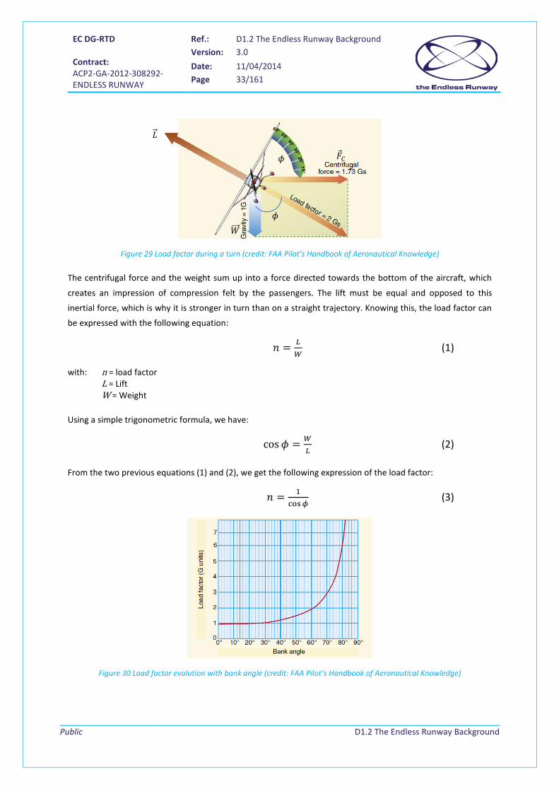
Figure 29 Load factor during a turn (credit: FAA Pilot’s Handbook of Aeronautical Knowledge)
The centrifugal force and the weight sum up into a force directed towards the bottom of the aircraft, which
creates an impression of compression felt by the passengers. The lift must be equal and opposed to this
inertial force, which is why it is stronger in turn than on a straight trajectory. Knowing this, the load factor can
be expressed with the following equation:
𝑛 = 𝐿𝑊
(1)
with: n = load factor L = Lift W = Weight
Using a simple trigonometric formula, we have:
cos𝜙 = 𝑊𝐿
(2)
From the two previous equations (1) and (2), we get the following expression of the load factor:
𝑛 = 1cos𝜙
(3)
Figure 30 Load factor evolution with bank angle (credit: FAA Pilot’s Handbook of Aeronautical Knowledge)
𝜙
𝑊���⃗
𝐿�⃗
𝜙 �⃗�𝐶

EC DG-RTD Contract: ACP2-GA-2012-308292- ENDLESS RUNWAY
Ref.: D1.2 The Endless Runway Background Version: 3.0
Date: 11/04/2014 Page 34/161
Public
D1.2 The Endless Runway Background
Bank angle Load factor Lift increase 0° 1 g 0 %
30° 1,15 g 15 %
45° 1,4 g 40 %
60° 2 g 100 %
Table 1 Bank angle versus load factor and lift increase
According to flight manuals, from a structural standpoint, standard aircraft have a limit load factor varying
between +3.8 g and -1.52 g. For acrobatics aircraft, values can range from +6 g to -3 g. The aircraft structure
must be capable of supporting 1.5 times the limit load factors without failure.
Load factors become significant as the bank increases beyond 45°. The approximate maximum bank angle for
general aviation aircraft is 60°, which corresponds to a load factor of 2 g.
A load factor limit is not only imposed by the aircraft structure, but also by the passengers. A passenger
subject to a load factor of 3 g would be pressed down into the seat with a force equal to three time his or her
weight.
2.3.2.2.2 On ground
Trains are designed so that passengers do not sustain a lateral acceleration higher than 1,2 m/s2, which
corresponds to 0,23 g. And a sportive car like the Pagani Zonea F Clubsport has a maximum lateral acceleration
of 1,4 g.
The value of the jerk should be considered as well.
2.4 Physical theory First equations related to the circular runway are detailed in this section (based on [18], [24], [25], [43]). First
estimates of circle radius and bank angles depending on aircraft speeds are given for a circular runway, based
on U.S. Navy hypothesis [18]. This will be refined in next deliverable, the operational concept of the Endless
Runway, where actual aircraft data will be considered.
As a first step, we will sum up the forces which apply to the aircraft without considering the wind and
assuming that the aircraft has a constant speed.
2.4.1 In-flight
Before landing on the circular runway or just after take-off, the aircraft is in-flight, with a bank angle as close as
possible as the bank angle of the runway at the point it took-off from or is about to land.
EC DG-RTD Contract: ACP2-GA-2012-308292- ENDLESS RUNWAY
Ref.: D1.2 The Endless Runway Background Version: 3.0
Date: 11/04/2014 Page 35/161
Public
D1.2 The Endless Runway Background
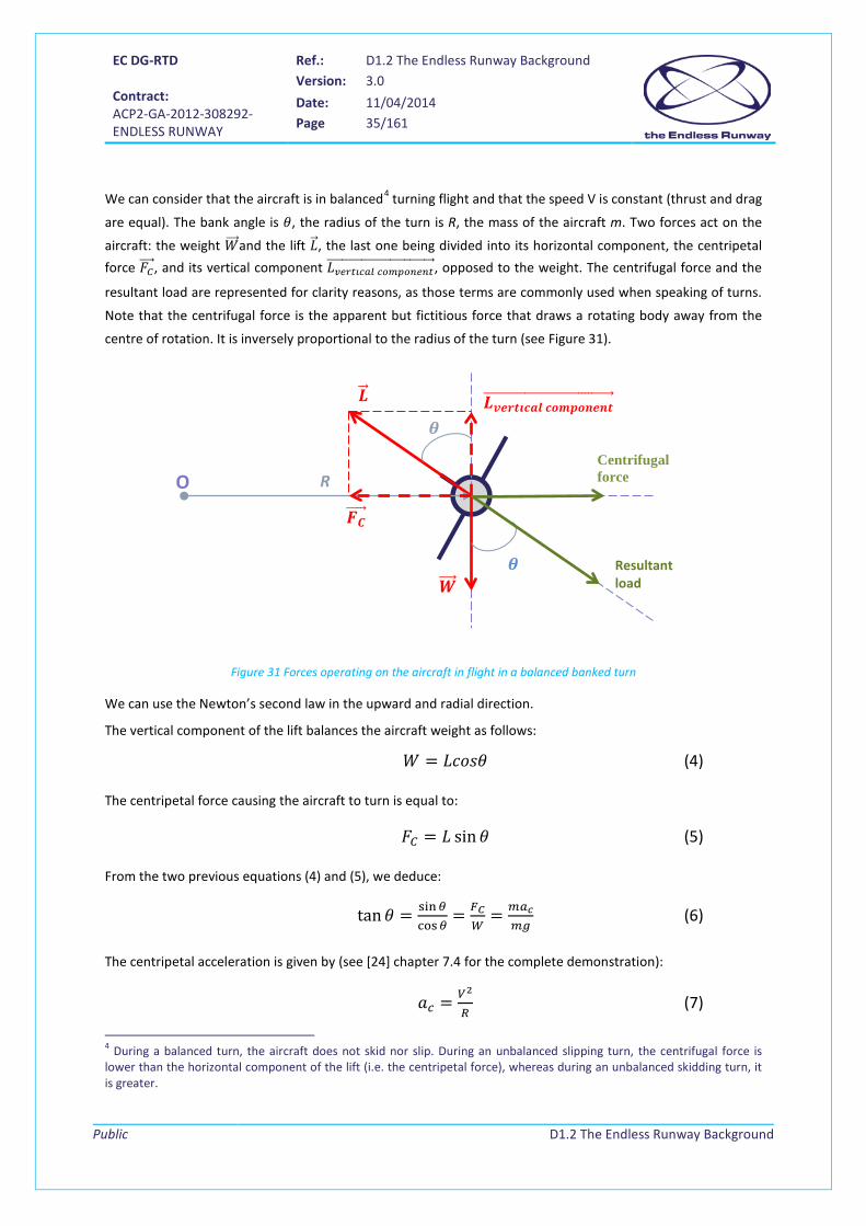
We can consider that the aircraft is in balanced4 turning flight and that the speed V is constant (thrust and drag
are equal). The bank angle is 𝜃, the radius of the turn is R, the mass of the aircraft m. Two forces act on the
aircraft: the weight 𝑊���⃗ and the lift 𝐿�⃗ , the last one being divided into its horizontal component, the centripetal force 𝐹𝐶����⃗ , and its vertical component 𝐿𝑣𝑒𝑟𝑡𝚤𝑐𝑎𝑙 𝑐𝑜𝑚𝑝𝑜𝑛𝑒𝑛𝑡������������������������������������⃗ , opposed to the weight. The centrifugal force and the
resultant load are represented for clarity reasons, as those terms are commonly used when speaking of turns.
Note that the centrifugal force is the apparent but fictitious force that draws a rotating body away from the
centre of rotation. It is inversely proportional to the radius of the turn (see Figure 31).
Figure 31 Forces operating on the aircraft in flight in a balanced banked turn
We can use the Newton’s second law in the upward and radial direction.
The vertical component of the lift balances the aircraft weight as follows:
𝑊 = 𝐿𝑐𝑜𝑠𝜃 (4)
The centripetal force causing the aircraft to turn is equal to:
𝐹𝐶 = 𝐿 sin𝜃 (5)
From the two previous equations (4) and (5), we deduce:
tan𝜃 = sin𝜃cos𝜃
= 𝐹𝐶𝑊
= 𝑚𝑎𝑐𝑚𝑔
(6)
The centripetal acceleration is given by (see [24] chapter 7.4 for the complete demonstration):
𝑎𝑐 = 𝑉2
𝑅 (7)
4 During a balanced turn, the aircraft does not skid nor slip. During an unbalanced slipping turn, the centrifugal force is lower than the horizontal component of the lift (i.e. the centripetal force), whereas during an unbalanced skidding turn, it is greater.
Centrifugal force
Resultant load
R O
𝑳𝒗𝒗𝒗𝒗𝒗𝒗𝒗𝒗 𝒗𝒄𝒄𝒄𝒄𝒄𝒗𝒄𝒗�������������������������������������⃗
𝜽
𝜽
𝑳��⃗
𝑾����⃗
𝑭𝑪����⃗

EC DG-RTD Contract: ACP2-GA-2012-308292- ENDLESS RUNWAY
Ref.: D1.2 The Endless Runway Background Version: 3.0
Date: 11/04/2014 Page 36/161
Public
D1.2 The Endless Runway Background
Therefore, the centripetal force is equal to:
𝐹𝐶 = 𝑚𝑎𝑐 = 𝑚𝑉2
𝑅 (8)
Knowing that:
𝑊 = 𝑚𝑔 (9)
with g the gravitational acceleration, we conclude from (6), (8) and (9):
tan𝜃 = 𝐹𝐶𝑊
= 𝑉2
𝑔𝑅 (10)
The value of the lift L is given by the following aerodynamic equation:
𝐿 = 𝐶𝐿𝜌𝑉2𝑆2
(11)
where 𝜌 is the density of the air (dependent on the altitude), 𝑉 is the true airspeed of the aircraft, 𝑆 is the wing
area and 𝐶𝐿 is the coefficient of lift. 𝐶𝐿 depends, amongst others, on the angle of attack.
Considering that the angle of attack is constant during approach in equation (11), equation (4) becomes:
𝑊 = 𝐶𝐿𝑎𝑝𝑝𝜌𝑉2𝑆2
𝑐𝑜𝑠𝜃 (12)
or:
𝑉2 = 𝑊𝐾1𝑐𝑜𝑠𝜃
(13)
with 𝐾1 =𝐶𝐿𝑎𝑝𝑝𝜌𝑆
2
Combining equations (10) and (13), we get:
𝑠𝑖𝑛𝜃 = 𝑡𝑎𝑛𝜃 · 𝑐𝑜𝑠𝜃 = 𝑉2
𝑔𝑅× 𝑊
𝐾1𝑉2= 𝑊
𝐾1𝑔𝑅 (14)
𝜃 = arcsin � 𝑊𝐾1𝑔𝑅
� (15)
2.4.2 On-ground
For equilibrium, the centrifugal force must be counteracted either by lateral friction developed between the
aircraft tyres and the runway surface alone, by the inward slope of the runway5 surface alone, or partially by
friction and partially by superelevation while the weight of the vehicle is balanced by the road reaction force
on the vehicle. Here the runway is banked to minimize the wearing out of the tyres due to friction.
5 This slope of the track is known in civil engineering for highways as the “superelevation”.
EC DG-RTD Contract: ACP2-GA-2012-308292- ENDLESS RUNWAY
Ref.: D1.2 The Endless Runway Background Version: 3.0
Date: 11/04/2014 Page 37/161
Public
D1.2 The Endless Runway Background
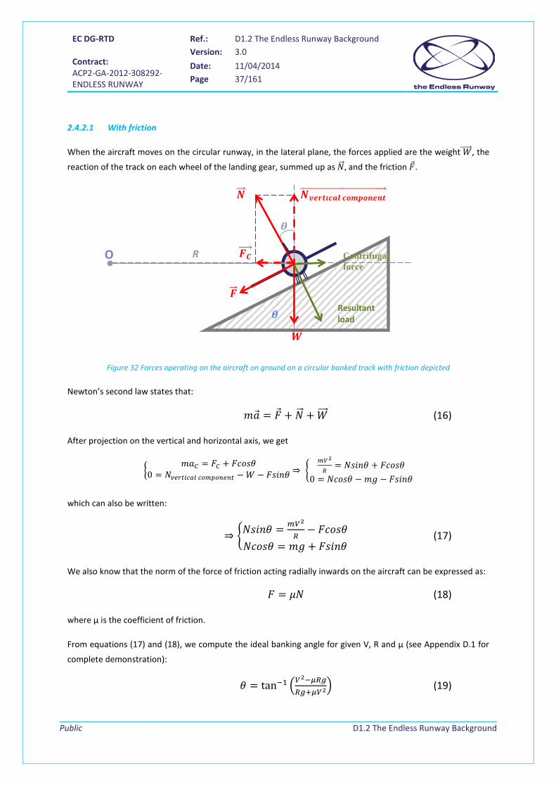
2.4.2.1 With friction
When the aircraft moves on the circular runway, in the lateral plane, the forces applied are the weight 𝑊�����⃗ , the
reaction of the track on each wheel of the landing gear, summed up as 𝑁��⃗ , and the friction �⃗�.
Figure 32 Forces operating on the aircraft on ground on a circular banked track with friction depicted
Newton’s second law states that:
𝑚�⃗� = �⃗� + 𝑁��⃗ + 𝑊���⃗ (16)
After projection on the vertical and horizontal axis, we get
�𝑚𝑎𝐶 = 𝐹𝐶 + 𝐹𝑐𝑜𝑠𝜃
0 = 𝑁𝑣𝑒𝑟𝑡𝑖𝑐𝑎𝑙 𝑐𝑜𝑚𝑝𝑜𝑛𝑒𝑛𝑡 − 𝑊 − 𝐹𝑠𝑖𝑛𝜃 ⇒ �𝑚𝑉2
𝑅= 𝑁𝑠𝑖𝑛𝜃 + 𝐹𝑐𝑜𝑠𝜃
0 = 𝑁𝑐𝑜𝑠𝜃 − 𝑚𝑔 − 𝐹𝑠𝑖𝑛𝜃
which can also be written:
⇒ �𝑁𝑠𝑖𝑛𝜃 = 𝑚𝑉2
𝑅− 𝐹𝑐𝑜𝑠𝜃
𝑁𝑐𝑜𝑠𝜃 = 𝑚𝑔 + 𝐹𝑠𝑖𝑛𝜃 (17)
We also know that the norm of the force of friction acting radially inwards on the aircraft can be expressed as:
𝐹 = 𝜇𝑁 (18)
where µ is the coefficient of friction.
From equations (17) and (18), we compute the ideal banking angle for given V, R and µ (see Appendix D.1 for
complete demonstration):
𝜃 = tan−1 �𝑉2−𝜇𝑅𝑔
𝑅𝑔+𝜇𝑉2� (19)
Centrifugal force
Resultant load
R O
𝑵𝒗𝒗𝒗𝒗𝒗𝒗𝒗𝒗 𝒗𝒄𝒄𝒄𝒄𝒄𝒗𝒄𝒗��������������������������������������⃗
𝜽
𝜽
𝑵��⃗
𝑾����⃗
𝑭𝑪����⃗
𝑭��⃗
EC DG-RTD Contract: ACP2-GA-2012-308292- ENDLESS RUNWAY
Ref.: D1.2 The Endless Runway Background Version: 3.0
Date: 11/04/2014 Page 38/161
Public
D1.2 The Endless Runway Background
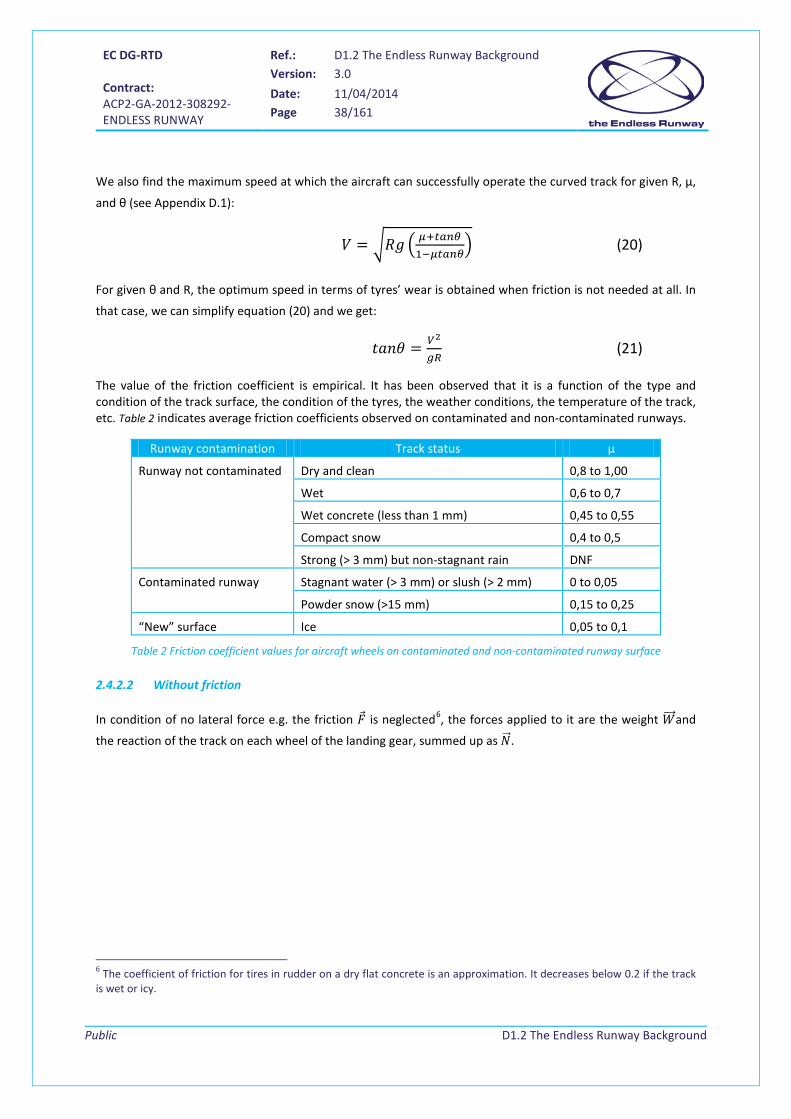
We also find the maximum speed at which the aircraft can successfully operate the curved track for given R, µ,
and θ (see Appendix D.1):
𝑉 = �𝑅𝑔 � 𝜇+𝑡𝑎𝑛𝜃1−𝜇𝑡𝑎𝑛𝜃
� (20)
For given θ and R, the optimum speed in terms of tyres’ wear is obtained when friction is not needed at all. In
that case, we can simplify equation (20) and we get:
𝑡𝑎𝑛𝜃 = 𝑉2
𝑔𝑅 (21)
The value of the friction coefficient is empirical. It has been observed that it is a function of the type and condition of the track surface, the condition of the tyres, the weather conditions, the temperature of the track, etc. Table 2 indicates average friction coefficients observed on contaminated and non-contaminated runways.
Runway contamination Track status µ
Runway not contaminated Dry and clean 0,8 to 1,00
Wet 0,6 to 0,7
Wet concrete (less than 1 mm) 0,45 to 0,55
Compact snow 0,4 to 0,5
Strong (> 3 mm) but non-stagnant rain DNF
Contaminated runway Stagnant water (> 3 mm) or slush (> 2 mm) 0 to 0,05
Powder snow (>15 mm) 0,15 to 0,25
“New” surface Ice 0,05 to 0,1
Table 2 Friction coefficient values for aircraft wheels on contaminated and non-contaminated runway surface
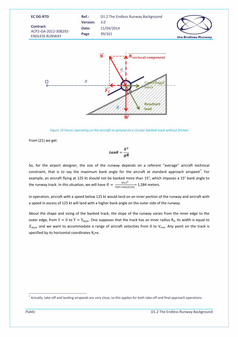
2.4.2.2 Without friction
In condition of no lateral force e.g. the friction �⃗� is neglected6, the forces applied to it are the weight 𝑊���⃗ and
the reaction of the track on each wheel of the landing gear, summed up as 𝑁��⃗ .
6 The coefficient of friction for tires in rudder on a dry flat concrete is an approximation. It decreases below 0.2 if the track is wet or icy.
EC DG-RTD Contract: ACP2-GA-2012-308292- ENDLESS RUNWAY
Ref.: D1.2 The Endless Runway Background Version: 3.0
Date: 11/04/2014 Page 39/161
Public
D1.2 The Endless Runway Background
Figure 33 Forces operating on the aircraft on ground on a circular banked track without friction
From (21) we get:
𝒗𝒗𝒄𝜽 =𝑽𝟐
𝒈𝑹
So, for the airport designer, the size of the runway depends on a referent “average” aircraft technical
constraint, that is to say the maximum bank angle for the aircraft at standard approach airspeed7. For
example, an aircraft flying at 125 kt should not be banked more than 15°, which imposes a 15° bank angle to
the runway track. In this situation, we will have 𝑅 = 64,32
9,81×tan (0,26)= 1,584 meters.
In operation, aircraft with a speed below 125 kt would land on an inner portion of the runway and aircraft with
a speed in excess of 125 kt will land with a higher bank angle on the outer side of the runway.
About the shape and sizing of the banked track, the slope of the runway varies from the inner edge to the
outer edge, from Y = 0 to Y = Ymax. One supposes that the track has an inner radius R0, its width is equal to
𝑋𝑚𝑎𝑥 and we want to accommodate a range of aircraft velocities from 0 to Vmax. Any point on the track is
specified by its horizontal coordinates R0+x.
7 Actually, take-off and landing airspeeds are very close, so this applies for both take-off and final approach operations.
Centrifugal force
Resultant load
R O
𝑵𝒗𝒗𝒗𝒗𝒗𝒗𝒗𝒗 𝒗𝒄𝒄𝒄𝒄𝒄𝒗𝒄𝒗��������������������������������������⃗
𝜽
𝜽
𝑵��⃗
𝑾����⃗
𝑭𝑪����⃗

EC DG-RTD Contract: ACP2-GA-2012-308292- ENDLESS RUNWAY
Ref.: D1.2 The Endless Runway Background Version: 3.0
Date: 11/04/2014 Page 40/161
Public
D1.2 The Endless Runway Background
Figure 34 Graph representing the banked track
As it can be seen from the previous chart, we have the following relationship between Y and X:
𝑡𝑎𝑛 𝜃 = 𝑑𝑦𝑑𝑥
(22)
From equation (21), we deduce:
𝑑𝑦𝑑𝑥
= 𝑉2
𝑔(𝑅0+𝑥) (23)
[18] assumes that 𝑉 = 𝑓(𝑥) = 𝐾𝑥, with K being a constant, and the previous expression can be integrated as
follows:
𝑦 =1𝑔𝑅0
�(𝐾𝑥)2
�1 + 𝑥𝑅0�
𝑋
0𝑑𝑥
The resolution of this integral is detailed in Appendix D.2.
Finally:
𝑲 = 𝑽𝒄𝒗𝒙
𝑾𝒗𝒖𝒄𝒘𝒗𝒚
𝒀𝒄𝒗𝒙 = 𝑲𝟐𝑹𝟎
𝟐
𝒈�𝟏𝟐𝑿𝟐
𝑹𝟎𝟐 −
𝑿𝑹𝟎
+ 𝐥𝐧 �𝟏 + 𝑿𝑹𝟎��
(24)
For a runway 91 meters wide with R0=1,509 meters and a maximum aircraft landing speed of 150 kt, we find:
𝐾 =150 × 0,5144444
91= 0,84
𝑌𝑚𝑎𝑥 = 0,842(1509)2
9,81�12
×912
15092−
911509
+ ln �1 +91
1509�� = 11,7 𝑚

EC DG-RTD Contract: ACP2-GA-2012-308292- ENDLESS RUNWAY
Ref.: D1.2 The Endless Runway Background Version: 3.0
Date: 11/04/2014 Page 41/161
Public
D1.2 The Endless Runway Background
The cross-section of the slope between R0 and R0+ Wrunway is decided by the designer. In [18], with R0=1,509 m
and Wrunway=91 m, it was decided that the slope would begin with a 1.5° on the inside at about R0 (inducing
friction at null speed) and the slope would increase with 2 degrees each 7.62 meters during the first 38.1
meters. Then, the remaining part of the slope would increase more slowly: 1.5° every further 7.62 meters. This
is depicted on Figure 35:
Figure 35 J.R Conrey banked runway, section view
The ground speed corresponding to each radius and slope is found using equations given above.

EC DG-RTD Contract: ACP2-GA-2012-308292- ENDLESS RUNWAY
Ref.: D1.2 The Endless Runway Background Version: 3.0
Date: 11/04/2014 Page 42/161
Public
D1.2 The Endless Runway Background
3 Alternative runway designs A circular runway, as proposed in the Endless Runway, is not the only attempt to change the airport
conventional design with one or more fixed, straight runways. In the past, several alternatives were presented
and still, in airport design, innovations alternative runway operations are proposed. One may note that the
preoccupations are the same for these other designs than for the Endless Runway: independency to the wind,
reduction of the space occupied, accessibility of the terminal building and decrease of the environmental
impact.
This chapter will present alternative runway designs in section 3.1 and will continue to present some
innovative ideas on airport design in general in section 3.2. Finally, the vision on the air transport system from
several groups will be presented.
3.1 The airport/runway at sea Aircraft carriers, currently solely in operation for military use, can be regarded as floating runways. Most of the
aircraft that use the deck are small fighter aircraft that allow for dedicated means like a catapult for take-off
and the use of arrester cables for landing as the forces on the aircraft and crew can be stressed significantly. In
Figure 36, a Rafale M is about to touch down on an aircraft carrier: the hook that will catch the arrester cable is
clearly visible. Dedicated means to protect the ship and its crew, like a jet blast deflector, are necessary and
special cranes or elevators will bring the aircraft to a lower deck for parking. Occasionally, other aircraft, like
helicopters and transport aircraft (Figure 37) use the carriers as well.
Figure 36 Rafale M landing on an aircraft carrier Figure 37 USAF / USN C17 carrier landing
Aircraft carriers are too short to be operated as basis for civil aircraft. One concept that would allow civil
aircraft use is the dedicated development of runways that float on the water. The first written concept of a
floating runway is a concept that was filed for a patent in 1931 from Clarence W. King [30] (see Figure 38).

EC DG-RTD Contract: ACP2-GA-2012-308292- ENDLESS RUNWAY
Ref.: D1.2 The Endless Runway Background Version: 3.0
Date: 11/04/2014 Page 43/161
Public
D1.2 The Endless Runway Background
Figure 38 Floating runway construction from Clarence W. King (1931)
Following this, several patents were filed on floating runways [33], [34], [35] or even floating airports [31],
[32], all focusing on the construction that can easily be disassembled when, for example, the weather requires
so (in case of expected storms). Some of the patents mention the fact that the runway or airport can be moved
or rotated in any desired direction relative to the water to align runways with the prevailing winds and
minimize the wind’s impact on its stability. Some structures can be easily detached and transported [37], or
even submersed when not in use [38]. Interesting also is the “ship to platform transformer” [39], where a ship
can be transformed from a vessel into a floating platform that can be used as a forward mobile air basis. The
list of patents referenced is not complete, but the mentioned ones give a good overview of ideas.
The idea of floating and rotating runways is still alive and recent intiatives include a “cruise home port”, which
is a floatable seaport and the floating airport from the out-of-the-box study [82] as can be seen in Figure 39,
Figure 40, and Figure 41.
Figure 39 Cruise home port top view Figure 40 Cruise home port with aircraft and ships

EC DG-RTD Contract: ACP2-GA-2012-308292- ENDLESS RUNWAY
Ref.: D1.2 The Endless Runway Background Version: 3.0
Date: 11/04/2014 Page 44/161
Public
D1.2 The Endless Runway Background
Figure 41 Floating airport from the Out-of-the-Box study
An airport with rotating runways inside the structure to allow landing in all wind directions was also thought of
(see Figure 42).
Figure 42 Airport in the sea with rotating runways
A conceptually easier idea consists of using the water as a landing surface for the aircraft with the airport
infrastructure built on land. If the water surface is large enough, the aircraft is able to land in any direction,
depending on the wind conditions. Water aircraft already use the principle, where in current practice small
aircraft can float to a quay and where for larger aircraft, the infrastructure for (de-)boarding and other aircraft
servicing is transported to the aircraft. One concept presents aircraft landing on a large water surface in any
direction and then floating to the land where docking facilities are present, like the one presented in the Out-
of-the-Box study [82] in Figure 43.
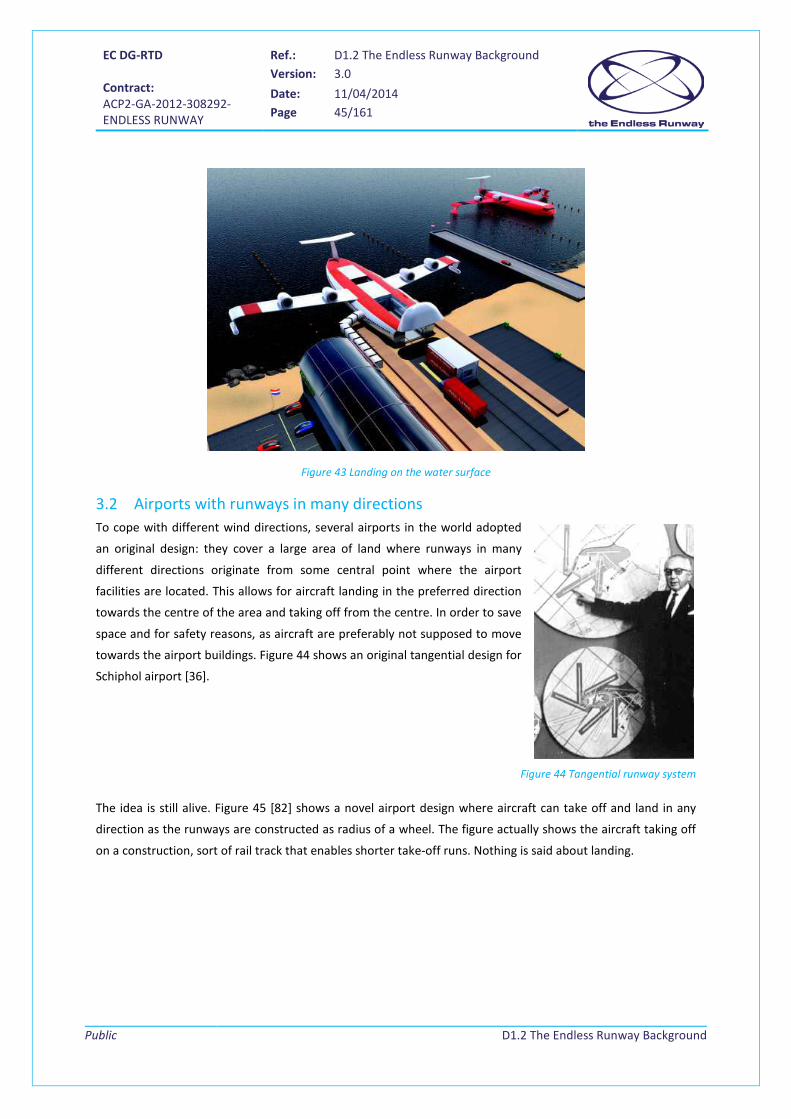
EC DG-RTD Contract: ACP2-GA-2012-308292- ENDLESS RUNWAY
Ref.: D1.2 The Endless Runway Background Version: 3.0
Date: 11/04/2014 Page 45/161
Public
D1.2 The Endless Runway Background
Figure 43 Landing on the water surface
3.2 Airports with runways in many directions To cope with different wind directions, several airports in the world adopted
an original design: they cover a large area of land where runways in many
different directions originate from some central point where the airport
facilities are located. This allows for aircraft landing in the preferred direction
towards the centre of the area and taking off from the centre. In order to save
space and for safety reasons, as aircraft are preferably not supposed to move
towards the airport buildings. Figure 44 shows an original tangential design for
Schiphol airport [36].
Figure 44 Tangential runway system
The idea is still alive. Figure 45 [82] shows a novel airport design where aircraft can take off and land in any
direction as the runways are constructed as radius of a wheel. The figure actually shows the aircraft taking off
on a construction, sort of rail track that enables shorter take-off runs. Nothing is said about landing.
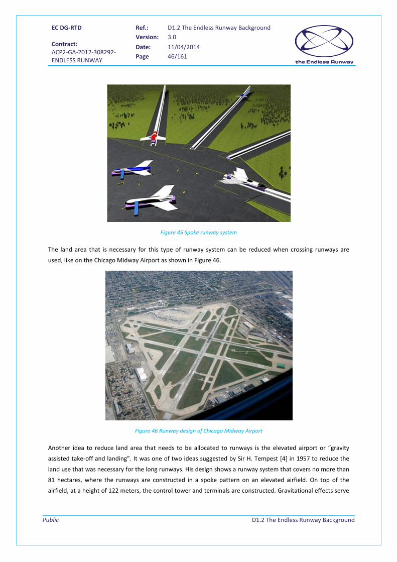
EC DG-RTD Contract: ACP2-GA-2012-308292- ENDLESS RUNWAY
Ref.: D1.2 The Endless Runway Background Version: 3.0
Date: 11/04/2014 Page 46/161
Public
D1.2 The Endless Runway Background
Figure 45 Spoke runway system
The land area that is necessary for this type of runway system can be reduced when crossing runways are
used, like on the Chicago Midway Airport as shown in Figure 46.
Figure 46 Runway design of Chicago Midway Airport
Another idea to reduce land area that needs to be allocated to runways is the elevated airport or “gravity
assisted take-off and landing”. It was one of two ideas suggested by Sir H. Tempest [4] in 1957 to reduce the
land use that was necessary for the long runways. His design shows a runway system that covers no more than
81 hectares, where the runways are constructed in a spoke pattern on an elevated airfield. On top of the
airfield, at a height of 122 meters, the control tower and terminals are constructed. Gravitational effects serve
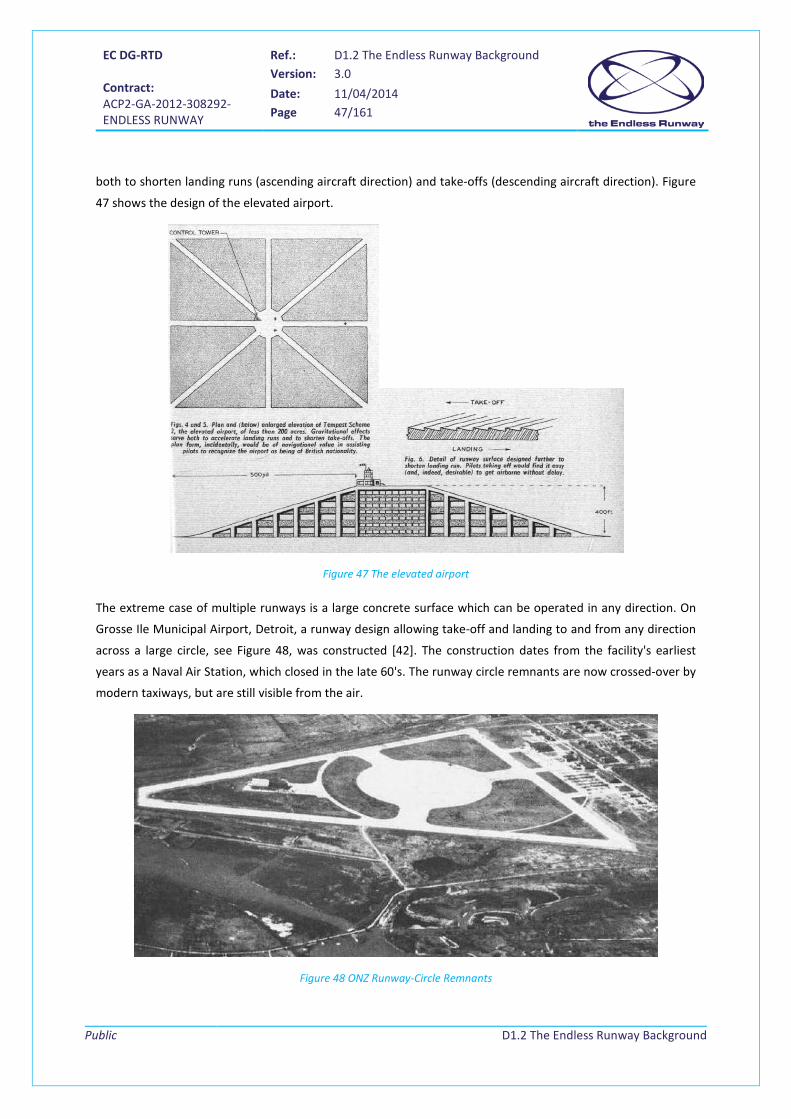
EC DG-RTD Contract: ACP2-GA-2012-308292- ENDLESS RUNWAY
Ref.: D1.2 The Endless Runway Background Version: 3.0
Date: 11/04/2014 Page 47/161
Public
D1.2 The Endless Runway Background
both to shorten landing runs (ascending aircraft direction) and take-offs (descending aircraft direction). Figure
47 shows the design of the elevated airport.
Figure 47 The elevated airport
The extreme case of multiple runways is a large concrete surface which can be operated in any direction. On
Grosse Ile Municipal Airport, Detroit, a runway design allowing take-off and landing to and from any direction
across a large circle, see Figure 48, was constructed [42]. The construction dates from the facility's earliest
years as a Naval Air Station, which closed in the late 60's. The runway circle remnants are now crossed-over by
modern taxiways, but are still visible from the air.
Figure 48 ONZ Runway-Circle Remnants

EC DG-RTD Contract: ACP2-GA-2012-308292- ENDLESS RUNWAY
Ref.: D1.2 The Endless Runway Background Version: 3.0
Date: 11/04/2014 Page 48/161
Public
D1.2 The Endless Runway Background
4 Vision of the Air Transport System of the future In order to analyse the different aspects of the Endless Runway, that is a prospective project that may not
emerge before 2050, it is first important to investigate what the future of air transport will look like and in
what direction travel, aircraft, and airport developments will evolve. In this chapter, a general vision on air
transport and ATM is provided. A good starting point is [70], on which the text of this chapter is largely based.
For this vision, the following sources have been consulted:
• the Vision and second Strategic Research Agenda of the Advisory Council for Aeronautics Research in
Europe (ACARE8) [71] [72] [73]
• the Vision and Phase 2 studies of the Association of European Research Establishments in Aeronautics
(EREA9) [63] [65]
• the Flightpath 2050 Vision document of the High Level Group on Aviation Research of the European
Commission (DG for Research and Innovation, DG for Mobility and Transport) [66]
ACARE presents, through the work of a “group of personalities”, the avionics research agenda for Europe, by
identifying challenges and opportunities for research and technology development. The EREA study, funded by
the Association of European Research Establishments in Aeronautics (EREA), aimed at providing to the
European aeronautical community the vision of the European research centres on the Air Transport System
(ATS) of the far future by the year 2050. In Phase 1 of the study, the vision of EREA is presented, based on the
four CONSAVE (Constrained Scenarios on Aviation and Emissions scenarios) of the ATS 2050 [74]. Phase 2, built
on these four scenarios, aims to further investigate the technical options identified in phase 1. The four
scenarios, see Figure 49 to Figure 52, are defined as follows:
• The scenario “Unlimited Skies” (ULS) represents a world that is not fundamentally constrained by
energy availability: the world is not governed by shortages, and as a consequence, aviation undergoes
explosive growth, with the development of many different types of aircraft.
• The scenario “Regulatory Push & Pull” (RPP), places emphasis on the public interest through a series
of constraints and regulations. These constraints are primarily in terms of energy (both the cost and
availability of fossil fuels becomes a deterrent) and the environment. This is a world dominated by
electricity largely produced by nuclear plants but also by wind and solar power and any other
technology using a natural resource in ecological fashion.
• The scenario “Down to Earth” (DTE), presenting a radical situation, reflects a political commitment to
eliminate fossil fuels usage. These fuels are not necessarily depleted, but society has decided to stop
tapping nature, and to freeze the remaining reserves as they are.
8 ACARE presents, through the work of a “group of personalities”, the avionics research agenda for Europe, by identifying challenges and opportunities for research and technology development. 9 The EREA study, funded by the Association of European Research Establishments in Aeronautics (EREA), aimed at providing to the European aeronautical community the vision of the European research centres on the Air Transport System (ATS) of the far future by the year 2050.

EC DG-RTD Contract: ACP2-GA-2012-308292- ENDLESS RUNWAY
Ref.: D1.2 The Endless Runway Background Version: 3.0
Date: 11/04/2014 Page 49/161
Public
D1.2 The Endless Runway Background
• The scenario Fractured World (FW), offers a brand-new geopolitical vision. The world has been
divided into very distinct blocs following major political and economic crises, partly caused by in-
equality in relation to the consequences of global warming and access to energy.
Figure 49 Scenario: Unlimited Skies
Figure 50 Scenario: Regulatory Push Pull
Figure 51 Scenario: Down to Earth
Figure 52 Scenario: Fractured World
The FlightPath 2050 study starts out by emphasizing the importance of European (and global) air transport. Air
transport not only ensures suitable mobility of passengers and freight, more interestingly the study also
stresses that aviation is a vital facilitator of (European and global) integration and cohesion by providing
essential transport links, generating a balance of trade and thereby wealth and economic growth.

EC DG-RTD Contract: ACP2-GA-2012-308292- ENDLESS RUNWAY
Ref.: D1.2 The Endless Runway Background Version: 3.0
Date: 11/04/2014 Page 50/161
Public
D1.2 The Endless Runway Background
4.1 Demand for air travel Regarding the demand for air travel, all studies assume that demand will grow towards 2050. The FlightPath
study expects that air traffic itself will grow accordingly, from 2.5 billion passengers in 2011 to 16 billion
passengers in 2050. Following Airbus’ Global market forecast 2010-2029, it is further stated that:
“World-wide traffic is predicted to grow at a rate of close at 4-5% per year with even higher growth
rates in the Middle East and Asia”
The ACARE study is less concrete in its estimates, but also anticipates a future growth of both air travel
demand and supply. About demand:
“With changing demographics and increased urbanisation, society towards 2050 will need more long-
range transport to connect markets and people. Passenger travel will increase with growth in business
and social-related mobility (dependent on the population being able to afford air travel). This
continuing growth in demand will bring increased challenges for dealing with mass transportation and
congestion of infrastructure.”
And regarding expected growth:
“The growth of air traffic over the past 50 years has been spectacular, and will continue in the future,
particularly in the growing markets of the Far East.”
4.2 Research agenda’s The ACARE Strategic Research Agenda (SRA) has outlined a number of goals to meet the demands of the
future. In the SRA 1 [71], the basis of nearly all aeronautical research programmes in Europe is provided, with a
focus on five challenges for aeronautical technology development: quality and affordability, environment,
safety, efficiency of the Air Transport System, and security. The more recent SRA 2 identifies - based on SRA1 -
six high level target concepts (HLTCs) for European aeronautical research:
1) a highly customer oriented air transport system,
2) a highly efficient air transport system,
3) a highly cost efficient air transport system,
4) an ultra-green air transportation system,
5) an ultra-secure air transport system,
6) 22nd century,
Just as well, FlightPath 2050 is in its vision document concrete about its goals, which can be summarized as
follows:
With respect to capacity/punctuality:

EC DG-RTD Contract: ACP2-GA-2012-308292- ENDLESS RUNWAY
Ref.: D1.2 The Endless Runway Background Version: 3.0
Date: 11/04/2014 Page 51/161
Public
D1.2 The Endless Runway Background
• 90% of travellers within Europe can complete their journey, door-to-door within 4 hours.
• Flights arrive within 1 minute of the planned arrival time regardless of weather conditions.
• An air traffic management system is in place that provides a range of services to handle at least 25
million flights a year.
With respect to the environment (reference is the year 2000):
• In 2050 technologies and procedures are available to allow a 75% reduction in CO2 emissions per
passenger kilometre to support a 90% reduction in NOx emissions.
• The perceived noise emission of flying aircraft is reduced by 65%.
• Aircraft movements are emission-free when taxiing.
• Air vehicles are designed and manufactured to be recyclable.
With respect to safety:
• Overall, the European air transport system has less than one accident per ten million commercial
aircraft flights.
• For specific operations, such as search and rescue, the aim is to reduce the number of accidents by
80% compared to 2000 taking into account increasing traffic.
4.3 Technology The Overall Air Transport system will have to cover future requirements and adapt the technology accordingly.
Therefore three levels are described in [67] that are summarized in Table 3
Technology adaption level Desciption Integration of Air Transport in the wider
transportation system
The role of air transport and the integration with other modes
of transport have to cope with the goals of [66]
Integrated Air Transport system Integrate all elements of air transport into one system that has
to be developed and improved as a whole
Develop individual elements In addition to the overall system, each element has to be
developed and improved in its own direction to address
specific and more detailed requirements.
Table 3 Technology adaption levels based on ACARE
The following four main blocks are identified by [67].
• airport
• air vehicle (including the power plant)
• air traffic management (ATM) system
• airline and operations, including maintenance, repair and overhaul (MRO) & training

EC DG-RTD Contract: ACP2-GA-2012-308292- ENDLESS RUNWAY
Ref.: D1.2 The Endless Runway Background Version: 3.0
Date: 11/04/2014 Page 52/161
Public
D1.2 The Endless Runway Background
The following chapters in this document will take the information of this chapter as a basis to further elaborate
aspects of the Endless Runway, concerning the airport design (chapter 5), ATM procedures (chapter 6), and
aircraft design (chapter 7).
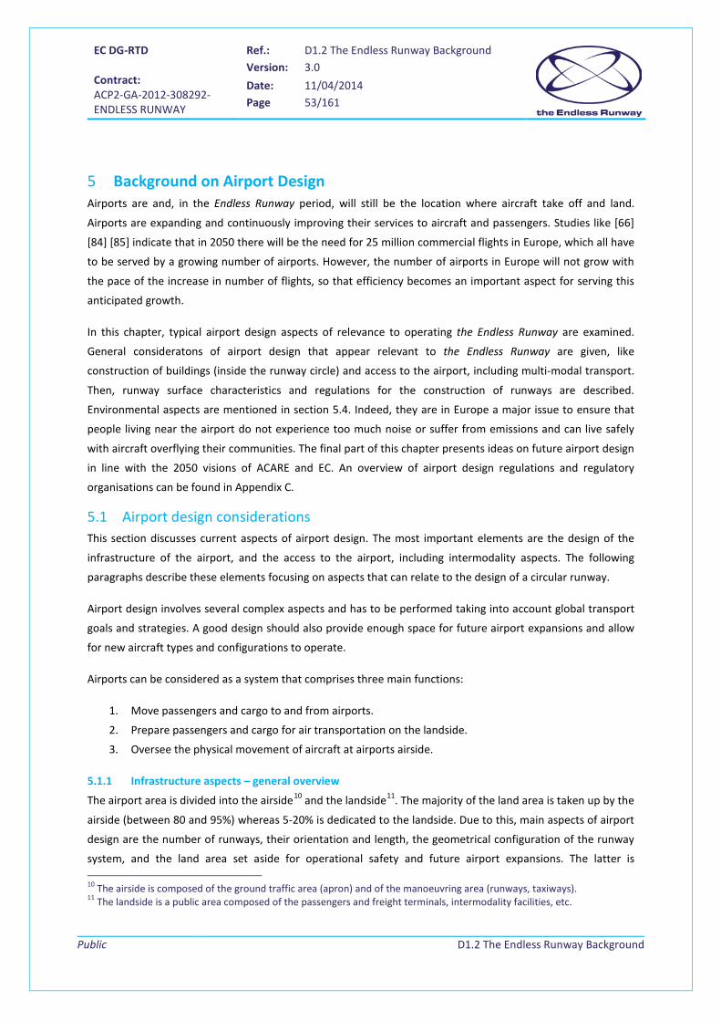
EC DG-RTD Contract: ACP2-GA-2012-308292- ENDLESS RUNWAY
Ref.: D1.2 The Endless Runway Background Version: 3.0
Date: 11/04/2014 Page 53/161
Public
D1.2 The Endless Runway Background
5 Background on Airport Design Airports are and, in the Endless Runway period, will still be the location where aircraft take off and land.
Airports are expanding and continuously improving their services to aircraft and passengers. Studies like [66]
[84] [85] indicate that in 2050 there will be the need for 25 million commercial flights in Europe, which all have
to be served by a growing number of airports. However, the number of airports in Europe will not grow with
the pace of the increase in number of flights, so that efficiency becomes an important aspect for serving this
anticipated growth.
In this chapter, typical airport design aspects of relevance to operating the Endless Runway are examined.
General consideratons of airport design that appear relevant to the Endless Runway are given, like
construction of buildings (inside the runway circle) and access to the airport, including multi-modal transport.
Then, runway surface characteristics and regulations for the construction of runways are described.
Environmental aspects are mentioned in section 5.4. Indeed, they are in Europe a major issue to ensure that
people living near the airport do not experience too much noise or suffer from emissions and can live safely
with aircraft overflying their communities. The final part of this chapter presents ideas on future airport design
in line with the 2050 visions of ACARE and EC. An overview of airport design regulations and regulatory
organisations can be found in Appendix C.
5.1 Airport design considerations This section discusses current aspects of airport design. The most important elements are the design of the
infrastructure of the airport, and the access to the airport, including intermodality aspects. The following
paragraphs describe these elements focusing on aspects that can relate to the design of a circular runway.
Airport design involves several complex aspects and has to be performed taking into account global transport
goals and strategies. A good design should also provide enough space for future airport expansions and allow
for new aircraft types and configurations to operate.
Airports can be considered as a system that comprises three main functions:
1. Move passengers and cargo to and from airports.
2. Prepare passengers and cargo for air transportation on the landside.
3. Oversee the physical movement of aircraft at airports airside.
5.1.1 Infrastructure aspects – general overview
The airport area is divided into the airside10 and the landside11. The majority of the land area is taken up by the
airside (between 80 and 95%) whereas 5-20% is dedicated to the landside. Due to this, main aspects of airport
design are the number of runways, their orientation and length, the geometrical configuration of the runway
system, and the land area set aside for operational safety and future airport expansions. The latter is 10 The airside is composed of the ground traffic area (apron) and of the manoeuvring area (runways, taxiways). 11 The landside is a public area composed of the passengers and freight terminals, intermodality facilities, etc.

EC DG-RTD Contract: ACP2-GA-2012-308292- ENDLESS RUNWAY
Ref.: D1.2 The Endless Runway Background Version: 3.0
Date: 11/04/2014 Page 54/161
Public
D1.2 The Endless Runway Background
important because of the trend of reconfiguring or expanding existing airports rather than building new ones.
The current airport runways, taxiways, and aprons must accommodate new and larger types of aircraft.
Changes must be made at the lowest expense. Thus long-range planning is absolutely essential. Moreover, the
airport designer must also take into account the interactions between the different airport subsystems
(runways, taxiways, landside buildings, etc.).
Safety also influences enormously the design process. Two organizations, the FAA (for the United States) and
ICAO (specifically, Annex 14 [26]) have a considerable importance in this respect. These two organizations have
similar design standards. Additionally, Annex 14 is supplemented by the ICAO Aerodrome Design Manual [28]
and, in the United Stated, by the FAA Advisory Circular 150/5300-13 [44].
For the airport design process, the following factors have to be taken into account:
• Geography • Location • History • Hydrology and Geology • Communication network • Meteorology
Meteorological factors need to be taken into account for the selection of an appropriate location when
designing an airport. They have huge influence on the runway orientation and they strongly influence airport
operations.
The main facilities to build are:
Airside Terminal Area Other facilities devoted to parallel activities
• Runways • Taxiways • Parking areas
• Passenger and Baggage management facilities
• Airliners facilities • Government facilities • Commercial areas
• Meteorological services • Control Tower • Fuel supply area • Hangars and garages • Platform vehicles parking
areas • Police and Emergency services • Ambulance and medical
services • Electric power station and
water supply • Cargo management area • Industrial and commercial area
The layout of airports until now follows a traditional set-up, as explained in Figure 53, which has been in use
since the beginning of aviation. Passengers and goods are collected at terminal buildings, runways are
connected to these terminals via (often long) taxiways, and passengers are transferred to the aircraft via gates
in the terminal building. At some airports passengers are transferred to the planes on the apron by buses
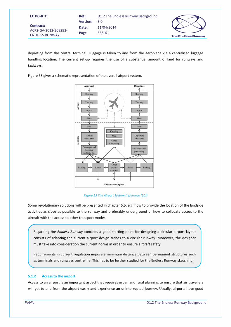
EC DG-RTD Contract: ACP2-GA-2012-308292- ENDLESS RUNWAY
Ref.: D1.2 The Endless Runway Background Version: 3.0
Date: 11/04/2014 Page 55/161
Public
D1.2 The Endless Runway Background
departing from the central terminal. Luggage is taken to and from the aeroplane via a centralised luggage
handling location. The current set-up requires the use of a substantial amount of land for runways and
taxiways.
Figure 53 gives a schematic representation of the overall airport system.
Figure 53 The Airport System (reference [50])
Some revolutionary solutions will be presented in chapter 5.5, e.g. how to provide the location of the landside
activities as close as possible to the runway and preferably underground or how to collocate access to the
aircraft with the access to other transport modes.
5.1.2 Access to the airport
Access to an airport is an important aspect that requires urban and rural planning to ensure that air travellers
will get to and from the airport easily and experience an uninterrupted journey. Usually, airports have good
Regarding the Endless Runway concept, a good starting point for designing a circular airport layout
consists of adapting the current airport design trends to a circular runway. Moreover, the designer
must take into consideration the current norms in order to ensure aircraft safety.
Requirements in current regulation impose a minimum distance between permanent structures such
as terminals and runways centreline. This has to be further studied for the Endless Runway sketching.

EC DG-RTD Contract: ACP2-GA-2012-308292- ENDLESS RUNWAY
Ref.: D1.2 The Endless Runway Background Version: 3.0
Date: 11/04/2014 Page 56/161
Public
D1.2 The Endless Runway Background
road access, although the construction of roads is a planning problem in itself as the large airside area of the
airport must be avoided. Larger airports have road tunnels passing under taxiways and runways.
Access by public transportation is becoming more important as roads tend to get congested.
An intermodal transport system is an integrated system where different transport means including ground, air,
and maritime transport are connected within a network where the users easily change from one to another
from the beginning to the end of their travel, enabling in this way efficient and uninterrupted goods and
persons transport.
5.1.2.1 Single mode transportation
Ground access places an important role in the current planning and airport design because it can constrain its
growth. Main access to the airport is done by car and by bus. Nowadays European and North American
airports are making an effort to reduce automobile traffic and promote public transportation. Some airports,
Boston/Logan for instance, try to restrict the parking space available in order to reduce the number of trips to
the airport. This measure has backfired because some people now drive the passengers to the airport,
employing two trips instead of one. Moreover public transportation is sometimes not convenient, which is
especially the case for families with lots of luggage and children who live far away from public transportation
facilities. However, due to public pressure, airport operators are investing in the creation of public
transportation access to airports. The most used public transportation intermodal links are: rail links, bus-train
links and airport-ferry connections. Many airports have extended underground, tram, and rail services to
provide travellers with a reliable way to access airports, preventing unnecessary traffic jams on the roads to
the airport. Many large cities use their bus network to complement the rail link. Some airports, Kansai to Kobe
for instance, are connected with ferries. Other ones, like Hong Kong International, provide ferry services to
several piers in the Pearl River Delta.
Table 4 shows the distribution of different transport modes to access the major European airports.
Ground access to the Endless Runway will need special consideration as any traveller from and to the
airport buildings, located inside the circle, will need to pass the runway ring.

EC DG-RTD Contract: ACP2-GA-2012-308292- ENDLESS RUNWAY
Ref.: D1.2 The Endless Runway Background Version: 3.0
Date: 11/04/2014 Page 57/161
Public
D1.2 The Endless Runway Background
Airport Car (%) Taxi (%) Bus (%) Train (%) Other (%) Amsterdam 52 13 6 25 4 Berlin/Tegel 34 45 17 - -
Brussels 55 20 - 25 - Köln 64 22 11 - 3
Düsseldorf 65 19 2 14 - Frankfurt 56 12 3 29 - Geneva 35 21 10 34 -
Hamburg 52 36 8 - 4 London/Gatwick 55 9 12 24 -
London/Heathrow 46 20 13 20 1 London/Stansted 69 8 10 12 1
Manchester 66 22 4 8 - Munich 43 8 7 42 -
Paris/CDG 54 14 9 23 - Paris/Orly 60 16 18 6 -
Zurich 29 8 29 34 -
Table 4 Transportation distribution in major European airports (source: Ingeniería Aeroportuaria; MGC)
People-mover systems or APMs (Automated People Movers) can assist the distribution of passengers between
different points inside an airport without walking excessively. As these systems can be very expensive, airport
operators must determine their viability. APMs have various common characteristics:
• Automated
• Designed for people
• Confined to special-purpose guideways reserved for their use
• Generally run as trains of 2 or 3 vehicles
• Operated horizontally (though there are exceptions, such as the system at Kuala
Lumpur/International, which drops two levels from boarding areas into a tunnel under the taxiways).
Figure 54 APM in London Heathrow airport
Figure 55 APM connecting Terminal 4 with Terminal 4S at
Madrid/Barajas ([55])

EC DG-RTD Contract: ACP2-GA-2012-308292- ENDLESS RUNWAY
Ref.: D1.2 The Endless Runway Background Version: 3.0
Date: 11/04/2014 Page 58/161
Public
D1.2 The Endless Runway Background
Various systems (examples are Figure 54 and Figure 55) have been developed depending on the distance
between two points. Systems longer than 600 meters use vehicles, consisting of a rubber-tired self-propelled
system. For shorter distances and simple routes, cable-driven systems are used, which are cheaper than the
former ones. There are roughly 30 APM systems currently in use worldwide.
5.1.2.2 Intermodal transport
In 2050 it is envisaged that the European Transport System will be integrated within a complete logistic
transport chain as part of a global aviation system completely interconnected.
Intermodality will play a main role in European future transport. It is
reflected in [99] and explained by the European Commission Vice President
responsible for Transport, Siim Kallas in [100]. He mentions that the aim of
the future transport system is to create a Single European Transport Area
with more competition and a fully integrated transport network that links
the different transport modes. The action cannot be delayed because
infrastructure takes many years to plan and build, and trains, planes, and
ships last for decades. Therefore, choices from today will determine the
shape of transport in 2050. For this reason, current revolutionary
initiatives, such as the Endless Runway, intend to transform Europe’s
current transport systems. These initiatives are expected in order to
achieve a fully integrated Single European Transport Area by 2050.
Figure 56 An integrated European Transport System in 2050
Cooperative systems, based on exchanges of information and communication between vehicles and also with
the road infrastructure, are developing rapidly. Interoperability between potential cooperative applications in
is the next challenge to reach a coherent and open system architecture [103].
By 2050, air transport systems will be thoroughly integrated with other transport modes and will well connect
the airport to the rest of the world, in order to meet the growing demand for travel [66].
Access to the airport buildings needs to be ensured for all transportation modes: cars, buses, trains,
and automated people movers. Cars and buses access to the buildings inside the circle should remain
limited. This is why they might have access to remote parking areas and bus stations, served by APMs.
Underground infrastructures appear as a good option for access to the buildings inside the circular
runway.
EC DG-RTD Contract: ACP2-GA-2012-308292- ENDLESS RUNWAY
Ref.: D1.2 The Endless Runway Background Version: 3.0
Date: 11/04/2014 Page 59/161
Public
D1.2 The Endless Runway Background
In the forthcoming years, European ground infrastructure will be in place for all airspace users. It will comprise
major hubs, secondary airports, vertiports, and heliports, all of them being seamlessly connected within a
multimodal transport system [66].
Interconnections within this network will be provided by multimodal transport, including high-speed trains for
the national or international network, trains, subways, tramways or suburban trains at regional airports,
electric ground vehicles, environmentally friendly ships, or even air-buses. A major goal for the future
intermodal transport system is to reduce dependence on the automobile as the major mode of ground
transportation and increase the use of public transport, especially in the context of the future air transport
system. To do so, one should have in mind that the Door to door journey has the user comfort as main driver.
Underground railway stations built below terminals reduce the need for private cars and limit the
environmental footprint. In 2050 the airport will be connected to a railway station integrated with the
landside. High Speed train for the national or international network will be available in all continental hubs as
well as secondary airports. Subway, tramway, or suburban train for the regional airport connected to the
nearby cities centers will be available.
5.2 Runway characteristics and regulations The construction of a circular runway will require the application of the same rules and regulations as are in
place in current runway construction, although some aspects will require further investigation and will need to
change. An obvious example is the proposed bank angle in the Endless Runway, something currently not
allowed, even more, not advisable when operating a straight runway track. Just as well, runway signs like the
runway number indicated on the strip’s surface will not be possible when on the Endless runway any position
of the runway can be used to land on.
The following sections give an overview of aspects of runway construction.
5.2.1 Runway orientation
Runways should ideally be aligned with the prevailing wind, to allow take-off and landing with headwind12. The
most critical wind in terms of safety is crosswind, especially for smaller aircraft with narrow landing gears. 12 Aircraft can also take-off and land with tail wind below a certain limit.
A move in airport access can be observed nowadays. Transport by car shall no longer be the major
means to arrive at the airport. A train station shall connect the airport to nearby cities and other
regional airports. High speed trains shall serve locations (cities and airports) further away.
The Endless Runway airport layout would have as one of the main requirements the connection with
the other transport means mentioned above, and the facilitation of the direct transfer from those
transports to the airport.

EC DG-RTD Contract: ACP2-GA-2012-308292- ENDLESS RUNWAY
Ref.: D1.2 The Endless Runway Background Version: 3.0
Date: 11/04/2014 Page 60/161
Public
D1.2 The Endless Runway Background
Wind considerations influence both the orientation and the number of runways. In fact, according to ICAO, any
runway should reach a 95% of wind coverage. If it is not possible, an additional crosswind runway should be
considered to bring the combined wind coverage of the two runways to at least 95%.
For information, the theoretical runway utilization rate is defined statistically as the ratio between the number
of observations where crosswind is below a certain rate (e.g. 26 kt) over the total number of observations
during a relevant timeframe (yearly or more specific period) on the closest meteorological station.
A wind rose is established to analyse wind data. Each concentric circle corresponds to a wind speed (m/s or kt)
and each radial line corresponds to the wind direction (°).
Figure 57 Determination of runway direction be wind rose analysis
On this wind rose, a crosswind template is drawn in red, see Figure 57. The spacing allowed (maximum
crosswind limit in the example: 7 m/s) determines the width of this crosswind template. The numbers in blue
represent the number of observations with a crosswind above the crosswind limit. Summed-up and divided by
the total number of observations and converted in a percentage, it should be below 5%.
The theoretical runway utilisation rate needs then to be confronted to other limiting factors, among others:
• Environmental constraints (noise)
• Topography of the aerodrome (pressure altitude) and of the surroundings (obstacles)

EC DG-RTD Contract: ACP2-GA-2012-308292- ENDLESS RUNWAY
Ref.: D1.2 The Endless Runway Background Version: 3.0
Date: 11/04/2014 Page 61/161
Public
D1.2 The Endless Runway Background
• Surrounding air traffic airways, especially if there are close aerodromes
• Aircraft performances
In terms of marking ([51]), every runway is designated by one tenth of its magnetic azimuth in the direction of
operations rounded to the nearest 10º. For example, a runway with a magnetic azimuth of 253º is marked 25,
and the other end (in the reverse direction) 07 (see Figure 58). Both side runways ends differ by 18, that is to
say, 180 º. If there are two parallel runways, the letters R (right) and L (left) are added. In case there are three
parallel runways, letters R, L and C are utilized (both ends are designated R and L, and the central runway is
named C). In the case of four parallel runways, the designations RR and LL are used for the outer runways.
Figure 58: Example of runway orientation: runway 07/25 [110]
Aircraft manufacturers provide for each aircraft a take-off run (TOR), a take-off distance (TOD) and a landing
distance for non-standard conditions. Airport designers must look at those published performances to
establish an optimal runway distance (runway + stopway + clearway).
5.2.2 Runway systems and airport capacity
Airport capacity is determined by the capacity of the terminal airspace, the runway system, the taxiway
system, the apron/gate area, the terminals and the access system. Each of these elements has to be carefully
considered by the airport designer, since the lowest capacity of these systems will determine the airport
capacity. For example, environmental restrictions and passenger delay are limiting capacity factors.
Obviously, runway orientation is for the construction of the Endless Runway not an issue. Still, the
location of the circular runway will need to be considered in relation to neighboring cities and the
prevailing wind conditions, so that the city will not be overflown during most of the time. Just as well,
the prevailing winds will determine where most aircraft will be originating from during landing and
need to be considered for the stopping distances and therefore for the construction of (high speed)
runway exits.
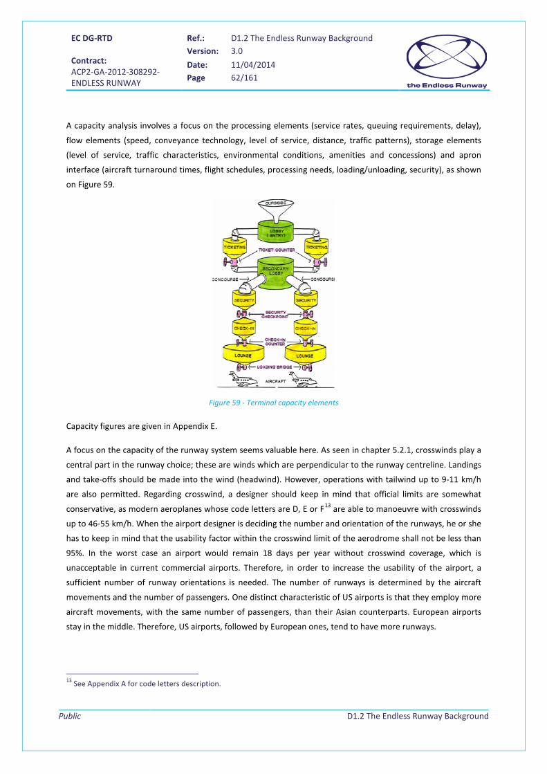
EC DG-RTD Contract: ACP2-GA-2012-308292- ENDLESS RUNWAY
Ref.: D1.2 The Endless Runway Background Version: 3.0
Date: 11/04/2014 Page 62/161
Public
D1.2 The Endless Runway Background
A capacity analysis involves a focus on the processing elements (service rates, queuing requirements, delay),
flow elements (speed, conveyance technology, level of service, distance, traffic patterns), storage elements
(level of service, traffic characteristics, environmental conditions, amenities and concessions) and apron
interface (aircraft turnaround times, flight schedules, processing needs, loading/unloading, security), as shown
on Figure 59.
Figure 59 - Terminal capacity elements
Capacity figures are given in Appendix E.
A focus on the capacity of the runway system seems valuable here. As seen in chapter 5.2.1, crosswinds play a
central part in the runway choice; these are winds which are perpendicular to the runway centreline. Landings
and take-offs should be made into the wind (headwind). However, operations with tailwind up to 9-11 km/h
are also permitted. Regarding crosswind, a designer should keep in mind that official limits are somewhat
conservative, as modern aeroplanes whose code letters are D, E or F13 are able to manoeuvre with crosswinds
up to 46-55 km/h. When the airport designer is deciding the number and orientation of the runways, he or she
has to keep in mind that the usability factor within the crosswind limit of the aerodrome shall not be less than
95%. In the worst case an airport would remain 18 days per year without crosswind coverage, which is
unacceptable in current commercial airports. Therefore, in order to increase the usability of the airport, a
sufficient number of runway orientations is needed. The number of runways is determined by the aircraft
movements and the number of passengers. One distinct characteristic of US airports is that they employ more
aircraft movements, with the same number of passengers, than their Asian counterparts. European airports
stay in the middle. Therefore, US airports, followed by European ones, tend to have more runways.
13 See Appendix A for code letters description.

EC DG-RTD Contract: ACP2-GA-2012-308292- ENDLESS RUNWAY
Ref.: D1.2 The Endless Runway Background Version: 3.0
Date: 11/04/2014 Page 63/161
Public
D1.2 The Endless Runway Background
Major airports usually have two parallel runways. Depending on the separation between them they are called
close, medium-spaced or independent parallel runways.
• The first type, close parallel runways, consists of those whose centreline separations are less than 762
m. If two aircraft operate in both runways under IFR (Instrument Flight Rules) the movements of
these two must be carefully coordinated. According to the ICAO and FAA, parallel operations of no
more than 214 m can be conducted in VFR, although the larger the aeroplanes the more distance
between them must be considered.
• The second case, medium-spaced parallel runways, also called segregated parallel operations, use a
runway for departures and the other one for arrivals. This runway system is used often. Nevertheless
it must be kept in mind that these movements are not independent and thus must be somehow
coordinated.
• Regarding independent parallel runways, their separation varies depending on the airport and on the
country. Separations greater than 1035 m, 1310 m and 1525 m are found. In this case simultaneous
operations do not need to be coordinated.
When operated under IFR, the independent parallel runways generate more capacity than the other two.
However, when operated under VFR (Visual Flight Rules) and good weather conditions, close and medium-
spaced runways may be able to obtain similar capacity than an independent pair.
There is usually enough space between independent parallel runways for the development of landside facilities
between them. Examples of this configuration include some of the busiest airports around the globe: Munich,
Singapore, Beijing, Hong Kong, Seoul/Incheon and Athens/Venizelos. The main advantages are: efficient use of
the area between runways, proximity between passenger and cargo buildings for both runways, better airfield
traffic circulation and an ability to isolate the airport’s landside from the surroundings. Nevertheless, some
issues can arise due to connecting landside facilities with highways or railways for accessing the airport. In this
case, an extensive taxiway system, including bridges (for example, in Munich) must be developed. Another
disadvantage consists of the difficult expansion of landside facilities due to not having sufficient space
between both runways (London/Heathrow is an example of that). In order to give a sizing estimation, an
airport with two parallel runways of 4 km length separated by no less than 1525 m would need 11 million m2,
or roughly 5 km by 2.2 km, which is not huge.
A “staggered” configuration (one threshold is farther along the central axis of the runway than the other one)
is used with independent parallel runways to provide additional separation between two aircraft operating
simultaneously. The main disadvantage of this configuration is that it needs more land area. Thus, land
acquisition costs are higher.
A combination of independent and close parallel runways may occur in some of the biggest airports, such as
Paris/Charles de Gaulle, Atlanta and Los Angeles /International, which receive more than 50 million passengers
annually. The complex of two pairs of close parallel runways separated by passenger buildings in the middle,
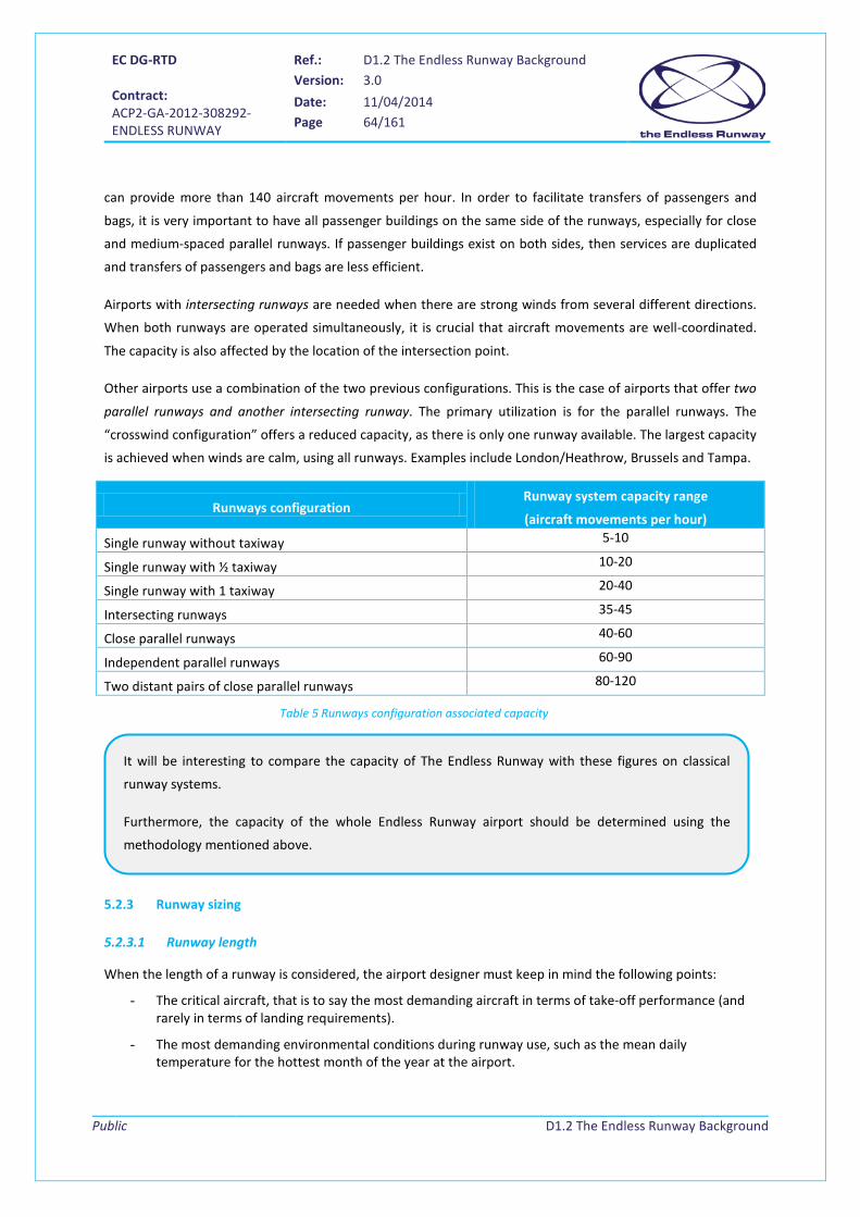
EC DG-RTD Contract: ACP2-GA-2012-308292- ENDLESS RUNWAY
Ref.: D1.2 The Endless Runway Background Version: 3.0
Date: 11/04/2014 Page 64/161
Public
D1.2 The Endless Runway Background
can provide more than 140 aircraft movements per hour. In order to facilitate transfers of passengers and
bags, it is very important to have all passenger buildings on the same side of the runways, especially for close
and medium-spaced parallel runways. If passenger buildings exist on both sides, then services are duplicated
and transfers of passengers and bags are less efficient.
Airports with intersecting runways are needed when there are strong winds from several different directions.
When both runways are operated simultaneously, it is crucial that aircraft movements are well-coordinated.
The capacity is also affected by the location of the intersection point.
Other airports use a combination of the two previous configurations. This is the case of airports that offer two
parallel runways and another intersecting runway. The primary utilization is for the parallel runways. The
“crosswind configuration” offers a reduced capacity, as there is only one runway available. The largest capacity
is achieved when winds are calm, using all runways. Examples include London/Heathrow, Brussels and Tampa.
Runways configuration Runway system capacity range
(aircraft movements per hour)
Single runway without taxiway 5-10
Single runway with ½ taxiway 10-20
Single runway with 1 taxiway 20-40
Intersecting runways 35-45
Close parallel runways 40-60
Independent parallel runways 60-90
Two distant pairs of close parallel runways 80-120
5.2.3 Runway sizing
5.2.3.1 Runway length
When the length of a runway is considered, the airport designer must keep in mind the following points:
- The critical aircraft, that is to say the most demanding aircraft in terms of take-off performance (and rarely in terms of landing requirements).
- The most demanding environmental conditions during runway use, such as the mean daily temperature for the hottest month of the year at the airport.
Table 5 Runways configuration associated capacity
It will be interesting to compare the capacity of The Endless Runway with these figures on classical
runway systems.
Furthermore, the capacity of the whole Endless Runway airport should be determined using the
methodology mentioned above.
EC DG-RTD Contract: ACP2-GA-2012-308292- ENDLESS RUNWAY
Ref.: D1.2 The Endless Runway Background Version: 3.0
Date: 11/04/2014 Page 65/161
Public
D1.2 The Endless Runway Background
- The obstacles that the aircraft needs to overfly with a 35 feet vertical margin [49].
Aircraft manufacturers provide for each aircraft a take-off run (TOR), a take-off distance (TOD) and a landing
distance for non-standard conditions. Airport designers must look at those published performances to
establish an optimal runway distance (runway + stopway + clearway).
Since published aircraft performance is given for standard conditions of temperature (15°C), pressure (sea
level), slope (null), a dry runway and in absence of wind, some correction factors need to be applied.
The aircraft flight manuals provide through dedicated charts the different landing and take-off lengths,
depending on temperature, slope and altitude. If the designer doesn’t have the manuals, the following
formulas are used to estimate the corrections needed [51]:
𝐹𝑎 = 1 +0.07𝑎300
𝐹𝑡 = 1 + 0.01(𝑡𝑟 − 𝑡𝑠ℎ)
𝐹𝑆 = 1 + 0.1𝑠
where: Fa = correction in altitude Ft = correction as a function of temperature Fs = correction as a function of slope a = altitude tr = reference temperature tsh = corresponding standard atmosphere to every altitude s = slope
If 𝐹𝑎 × 𝐹𝑠 × 𝐹𝑡 > 1.35, the preceding formulas are not applicable and a specific study must be done.
Therefore, once the take-off and landing lengths are known, the final runway length will be the largest
between the take-off and the landing length with the corrections Ft, Fs and Fa applied.
As an example, let’s suppose that the take-off and landing lengths in standard conditions are 1,550 m and
1,700 m. The altitude of the airport is 500 m, its effective slope 0.5%, the reference temperature is 23°C and
the reference temperature at sea level 15°C.
𝐹𝑎 = 1 +0.07𝑎300
= 1 +0.07 × 500
300= 1.117
𝐹𝑡 = 1 + 0.01(𝑡𝑟 − 𝑡𝑠ℎ) = 1 + 0.01 × (23 − 15) = 1.08
𝐹𝑆 = 1 + 0.1𝑠 = 1 + 0.1 × 0.5 = 1.05
The validity of the formulas is established since 𝐹𝑎 × 𝐹𝑠 × 𝐹𝑡 = 1.08 × 1.05 × 1.117 = 1.27 < 1.35.
Thus, we get:

EC DG-RTD Contract: ACP2-GA-2012-308292- ENDLESS RUNWAY
Ref.: D1.2 The Endless Runway Background Version: 3.0
Date: 11/04/2014 Page 66/161
Public
D1.2 The Endless Runway Background
Take-off length = 1550 × 1.08 × 1.05 × 1.117 = 1963 𝑚
Landing length = 1700 × 1.05 × 1.117 = 1994 𝑚
Therefore, runway length= max(1963, 1994) = 1994 𝑚.
Table 6 Runway lengths for different aircraft categories
gives an overview of necessary runway lengths for different aircraft categories.
Aircraft category Runway length (m) Regional jets and many short-range flights (up to 2000 km) 2,000
Short-to-medium-range flights (3000 km) 2,300
Medium range flights (4500 km) 2,700
Longer range flights (9000 km) 3,200
All range flights (11500-13100 km) 3,500-4,000
Table 6 Runway lengths for different aircraft categories
5.2.3.2 Declared distances
Airports declare four runway distances to the attention of the airspace users: the TORA (Take-Off Run
Available), the TODA (Take-Off Distance Available), the ASDA (Accelerate-Stop Distance Available) and the LDA
(Landing Distance Available) [51], see Figure 60 and the Definitions chapter.
Figure 60 Runway declared distances
Runway length in relation to the necessary take-off and landing length is no issue on the Endless
Runway (as the name says). For separation issues, the above given figures are important and need to be
considered.
Runway Stopway Clearway
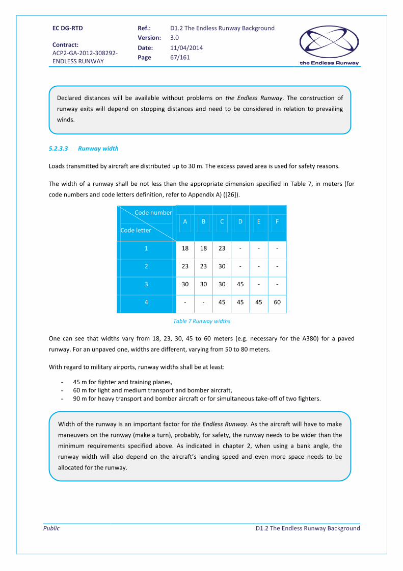
EC DG-RTD Contract: ACP2-GA-2012-308292- ENDLESS RUNWAY
Ref.: D1.2 The Endless Runway Background Version: 3.0
Date: 11/04/2014 Page 67/161
Public
D1.2 The Endless Runway Background
5.2.3.3 Runway width
Loads transmitted by aircraft are distributed up to 30 m. The excess paved area is used for safety reasons.
The width of a runway shall be not less than the appropriate dimension specified in Table 7, in meters (for
code numbers and code letters definition, refer to Appendix A) ([26]).
Code number
Code letter A B C D E F
1 18 18 23 - - -
2 23 23 30 - - -
3 30 30 30 45 - -
4 - - 45 45 45 60
Table 7 Runway widths
One can see that widths vary from 18, 23, 30, 45 to 60 meters (e.g. necessary for the A380) for a paved
runway. For an unpaved one, widths are different, varying from 50 to 80 meters.
With regard to military airports, runway widths shall be at least:
- 45 m for fighter and training planes, - 60 m for light and medium transport and bomber aircraft, - 90 m for heavy transport and bomber aircraft or for simultaneous take-off of two fighters.
Declared distances will be available without problems on the Endless Runway. The construction of
runway exits will depend on stopping distances and need to be considered in relation to prevailing
winds.
Width of the runway is an important factor for the Endless Runway. As the aircraft will have to make
maneuvers on the runway (make a turn), probably, for safety, the runway needs to be wider than the
minimum requirements specified above. As indicated in chapter 2, when using a bank angle, the
runway width will also depend on the aircraft’s landing speed and even more space needs to be
allocated for the runway.

EC DG-RTD Contract: ACP2-GA-2012-308292- ENDLESS RUNWAY
Ref.: D1.2 The Endless Runway Background Version: 3.0
Date: 11/04/2014 Page 68/161
Public
D1.2 The Endless Runway Background
5.2.4 Runway safety areas and protection zones
5.2.4.1 Runway safety area
The runway safety area (RSA) includes (see Figure 61 and Table 8): the structural pavement, runway shoulders,
runway blast pads, and stopways. An object situated on a runway end safety area which may endanger
aeroplanes shall be regarded as an obstacle and shall, as far as practical, be removed.
Figure 61 Runway Safety Area
RSA length from the end
of the runway strip
RSA
width
RSA
longitudinal slope
RSA
transversal slope
120 m for aerodrome codes 1 and 2 At least twice that of
the associated runway. <5% downward <5% upward or
downward 240 m for aerodrome codes 3 and 4
Table 8 Runway Safety Area characteristics
A shoulder is defined by the ICAO as an area adjacent to the edge of a pavement so prepared as to provide a
transition between the pavement and the adjacent surface. It shall be capable, in the event of an aeroplane
running off the runway, of supporting the aeroplane without inducing structural damage to the aeroplane and
to supporting ground. Although a turf may be enough, it is recommended that the runway shoulders are
paved, mainly for runways that accommodate code letter C and above (see Appendix A for ICAO codes).
Letters E and F usually require paved shoulders.
Runway shoulders shall be provided in the following conditions:
1. Runway with code letters D or E and whose width is less than 60 m. 2. Runway with code F.

EC DG-RTD Contract: ACP2-GA-2012-308292- ENDLESS RUNWAY
Ref.: D1.2 The Endless Runway Background Version: 3.0
Date: 11/04/2014 Page 69/161
Public
D1.2 The Endless Runway Background
As far as width is concerned, they extend symmetrically on each side of the runway so that the overall width of
it and its shoulders is not less than:
3. 60 m for code letters D and E. 4. 75 m for code letter F.
Another characteristic of a runway shoulder is that its transverse slope shall not exceed 2.5% and the surface of it that abuts the runway shall be flush with the surface of the runway.
The goal of a blast pad is to protect the runway against the damage made by jet blasts. They should extend
across the full length of the runway and its shoulders.
5.2.4.2 Runway protection zones
According to FAA, the obstacle free-zone (OFZ) (see Figure 62) is aimed at providing clearance protection for
aircraft landing or taking off and for missed approaches. It is centred above the runway and extends to 45 m
above the established airport elevation. It is subdivided into three parts:
1. Runway OFZ: the airspace above a surface centred on the runway centreline. 2. Inner-approach OFZ: centred on the extended runway centreline and applicable only to runways with
an approach lighting system. 3. Inner- transitional OFZ: the airspace above the surfaces located on the outer edges of the runway OFZ
and the inner-approach OFZ.
Runway blast pads will not be necessary for operations on the Endless Runway as behind the aircraft,
there will always be more runway. Possibly, however, the runway safety area can be prone to jet
blast, as the aircraft is making a turn, creating jet blast over the runway shoulder, see figure below.
Shoulders and runway safety areas around the circle should also be taken into account, especially on
the inner part of the circle.
Take off direction
Jet blast
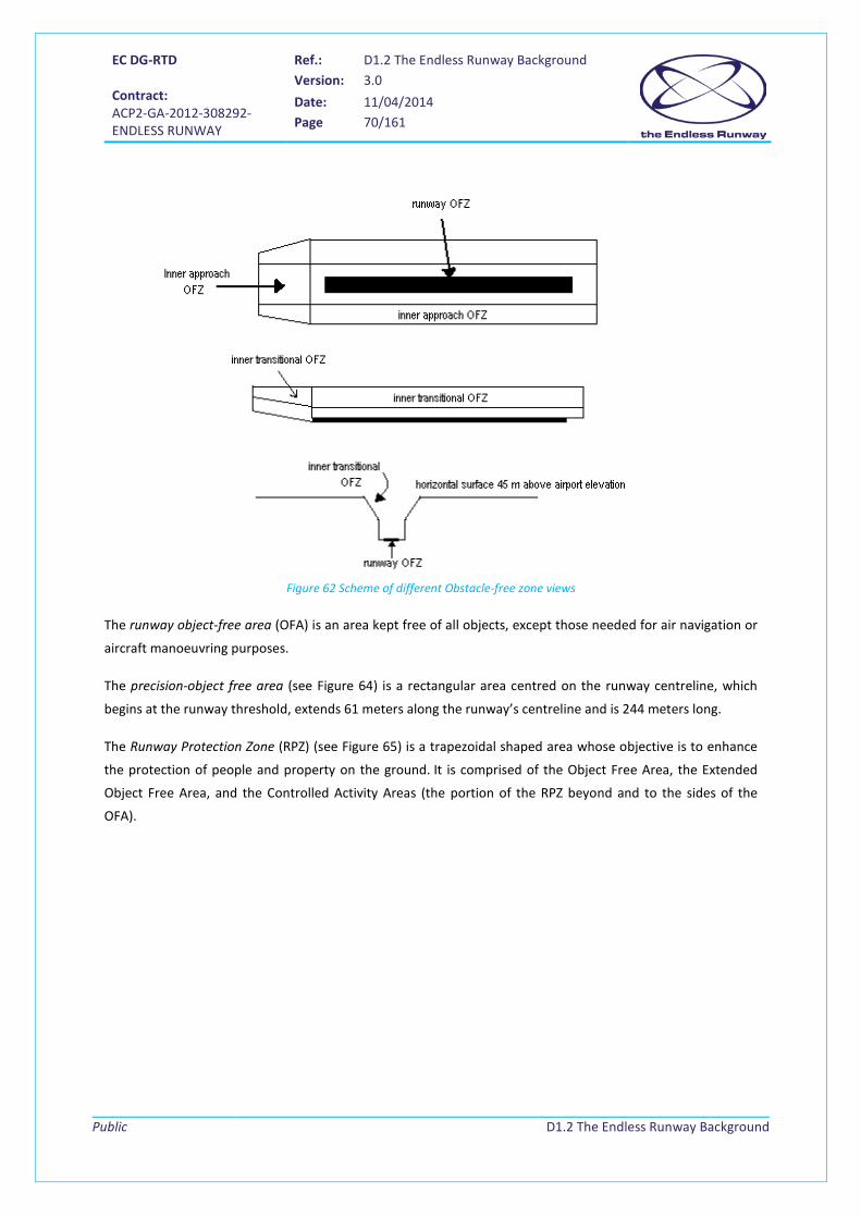
EC DG-RTD Contract: ACP2-GA-2012-308292- ENDLESS RUNWAY
Ref.: D1.2 The Endless Runway Background Version: 3.0
Date: 11/04/2014 Page 70/161
Public
D1.2 The Endless Runway Background
Figure 62 Scheme of different Obstacle-free zone views
The runway object-free area (OFA) is an area kept free of all objects, except those needed for air navigation or
aircraft manoeuvring purposes.
The precision-object free area (see Figure 64) is a rectangular area centred on the runway centreline, which
begins at the runway threshold, extends 61 meters along the runway’s centreline and is 244 meters long.
The Runway Protection Zone (RPZ) (see Figure 65) is a trapezoidal shaped area whose objective is to enhance
the protection of people and property on the ground. It is comprised of the Object Free Area, the Extended
Object Free Area, and the Controlled Activity Areas (the portion of the RPZ beyond and to the sides of the
OFA).

EC DG-RTD Contract: ACP2-GA-2012-308292- ENDLESS RUNWAY
Ref.: D1.2 The Endless Runway Background Version: 3.0
Date: 11/04/2014 Page 71/161
Public
D1.2 The Endless Runway Background
Figure 64 Scheme of POFZ, FAA annex 16Z
Figure 65 Scheme of RPZ
According to ICAO, obstacle limitation surfaces define the limits to which objects may project into the airspace.
They comprise the following (for more details, go to the Definitions chapter):
1. Transitional surface
2. Inner transitional surface
3. Inner approach surface
4. Approach surface
5. Balked landing surface
6. Conical surface
7. Inner horizontal surface
8. Take-off climb surface

EC DG-RTD Contract: ACP2-GA-2012-308292- ENDLESS RUNWAY
Ref.: D1.2 The Endless Runway Background Version: 3.0
Date: 11/04/2014 Page 72/161
Public
D1.2 The Endless Runway Background
Figure 66 Obstacle limitation surfaces: inner transitional, inner approach and balked landing (Source: ICAO[26])
Figure 67 Obstacle limitation surfaces (Source: ICAO [26])
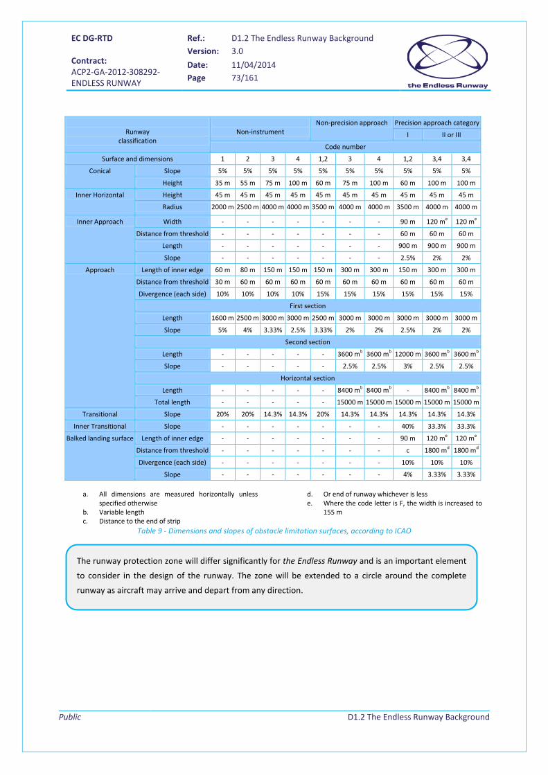
EC DG-RTD Contract: ACP2-GA-2012-308292- ENDLESS RUNWAY
Ref.: D1.2 The Endless Runway Background Version: 3.0
Date: 11/04/2014 Page 73/161
Public
D1.2 The Endless Runway Background
Runway
classification
Non-instrument
Non-precision approach Precision approach category
I II or III
Code number
Surface and dimensions 1 2 3 4 1,2 3 4 1,2 3,4 3,4
Conical Slope 5% 5% 5% 5% 5% 5% 5% 5% 5% 5%
Height 35 m 55 m 75 m 100 m 60 m 75 m 100 m 60 m 100 m 100 m
Inner Horizontal Height 45 m 45 m 45 m 45 m 45 m 45 m 45 m 45 m 45 m 45 m
Radius 2000 m 2500 m 4000 m 4000 m 3500 m 4000 m 4000 m 3500 m 4000 m 4000 m
Inner Approach Width - - - - - - - 90 m 120 me 120 me
Distance from threshold - - - - - - - 60 m 60 m 60 m
Length - - - - - - - 900 m 900 m 900 m
Slope - - - - - - - 2.5% 2% 2%
Approach Length of inner edge 60 m 80 m 150 m 150 m 150 m 300 m 300 m 150 m 300 m 300 m
Distance from threshold 30 m 60 m 60 m 60 m 60 m 60 m 60 m 60 m 60 m 60 m
Divergence (each side) 10% 10% 10% 10% 15% 15% 15% 15% 15% 15%
First section
Length 1600 m 2500 m 3000 m 3000 m 2500 m 3000 m 3000 m 3000 m 3000 m 3000 m
Slope 5% 4% 3.33% 2.5% 3.33% 2% 2% 2.5% 2% 2%
Second section
Length - - - - - 3600 mb 3600 mb 12000 m 3600 mb 3600 mb
Slope - - - - - 2.5% 2.5% 3% 2.5% 2.5%
Horizontal section
Length - - - - - 8400 mb 8400 mb - 8400 mb 8400 mb
Total length - - - - - 15000 m 15000 m 15000 m 15000 m 15000 m
Transitional Slope 20% 20% 14.3% 14.3% 20% 14.3% 14.3% 14.3% 14.3% 14.3%
Inner Transitional Slope - - - - - - - 40% 33.3% 33.3%
Balked landing surface Length of inner edge - - - - - - - 90 m 120 me 120 me
Distance from threshold - - - - - - - c 1800 md 1800 md
Divergence (each side) - - - - - - - 10% 10% 10%
Slope - - - - - - - 4% 3.33% 3.33%
a. All dimensions are measured horizontally unless specified otherwise
b. Variable length c. Distance to the end of strip
d. Or end of runway whichever is less e. Where the code letter is F, the width is increased to
155 m
Table 9 - Dimensions and slopes of obstacle limitation surfaces, according to ICAO
The runway protection zone will differ significantly for the Endless Runway and is an important element
to consider in the design of the runway. The zone will be extended to a circle around the complete
runway as aircraft may arrive and depart from any direction.

EC DG-RTD Contract: ACP2-GA-2012-308292- ENDLESS RUNWAY
Ref.: D1.2 The Endless Runway Background Version: 3.0
Date: 11/04/2014 Page 74/161
Public
D1.2 The Endless Runway Background
5.2.4.3 Runway dimensions overview
In Table 10, an overview of the runway dimensions and the dimensions of the runway safety area and runway
object-free area is given. The figures refer to lengths which begin at each runway end, when a stopway is not
provided; if not, they begin at the stopway end.
Aircraft design group I II III IV V VI
Runway width 30 m 30 m 30 m 45 m 45 m 60 m Runway shoulder width 3 m 3 m 6 m 7.5 m 10.5 m 12 m Runway blast pad width 36 m 36 m 42 m 60 m 66 m 84 m Runway blast pad length 30 m 45 m 60 m 60 m 120 m 30 m Runway safety area width 150 m Runway safety area width beyond RW end 300 m Obstacle-free zone width 120 m Obstacle-free zone length beyond RW end 60 m Runway object-free area 240 m Runway object-free area length beyond RW end 300 m
Table 10 Dimensional standards for runways (source: FAA)
5.2.5 Maximum runway slope
On one hand ([51]), according to FAA standards, for categories C, D and E, the maximum longitudinal grade
allowed is ±1.5%. Nevertheless a ±0.8% grade may not be exceeded in the first and last quarter of the runway
length. At the same time, the maximum allowable grade change is ±1.5%. The longitudinal grades applied to a
runway should be applied to the entire runway safety area (RSA).
On the other hand, according to ICAO Annex 14 [26], longitudinal slope changes allowed are summarized in
the following table for ICAO code element 1.
Code number 1, 2 Code number 3 Code number 4
Max-Min elevation centre line/runway length 2% 1% 1%
Longitudinal slope along any point 2% 1.5%14 1.25%15
Slope change between 2 consecutive slopes 2% 1.5% 1.5%
Transition to one slope to another 0.4% per 30 m16 0.2% per 30 m17 0.1% per 30 m18
Table 11 ICAO longitudinal runway slope
14 except that for the first and last quarter of the length of the runway, in case of precision approaches Category II and III, the longitudinal slope shall not exceed 0.8%. 15 except that for the first and last quarter of the length of the runway the longitudinal slope shall not exceed 0.8%. 16 a curved surface with minimum radius of curvature of 7500 m 17 a curved surface with minimum radius of curvature of 15000 m 18 a curved surface with minimum radius of curvature of 30000 m

EC DG-RTD Contract: ACP2-GA-2012-308292- ENDLESS RUNWAY
Ref.: D1.2 The Endless Runway Background Version: 3.0
Date: 11/04/2014 Page 75/161
Public
D1.2 The Endless Runway Background
Where slope changes cannot be avoided, they shall be such that there will be an unobstructed line of sight
from:
• Any point 1.5 m above a runway to all other points 1.5 m above the runway within a distance of at
least half the length of the runway where the code letter is A.
• Any point 2 m above a runway to all other points 2 m above the runway within a distance of at least
half the length of the runway where the code letter is B.
• Any point 3 m above a runway to all other points 3 m above the runway within a distance of at least
half the length of the runway where the code letter is C, D, E or F.
5.2.6 Transversal runway profile
According to FAA [51], for airport categories C and D, the runway or taxiway grades shall not exceed 1% to
1.5%, the grades for shoulders 1.5% to 5% and the rest of the runway or taxiway safety area shall not exceed
1.5% to 3%.
As far as ICAO is concerned [26], the transverse slope shall be:
• 2% for code letters A and B.
• 1.5% for code letters C, D, E and F.
It has to be mentioned that, in any event, the transverse slope shall not exceed 1.5% or 2%, as applicable, nor
be less than 1% except at runway or taxiway intersections where flatter slopes may be necessary. Besides, the
slope on each side of the centre line shall be symmetrical. It shall be substantially the same throughout the
length of a runway except at an intersection with another runway or taxiway where an even transition shall be
provided taking account the need or adequate drainage.
Apart from the proposed bank angle on the Endless Runway, the area for constructing the runway is
larger than for straight runways of three to four kilometers. The consequence of this may be that a
slope is necessary. The same regulations as given in this section will apply for the Endless Runway.
The designer has to take into account the force 𝑊𝑠𝑖𝑛Φ (with φ: runway longitudinal slope angle and W: aircraft weight), especially for large aircraft. Given that slopes are small, 𝑊𝑠𝑖𝑛Φ~WΦ.
Aircraft performance along the circle must be as even as possible. Therefore there shall not be
significant slope variations along the circle (in opposed areas). For this, the surface where the
circular runway is located should not be inclined.
EC DG-RTD Contract: ACP2-GA-2012-308292- ENDLESS RUNWAY
Ref.: D1.2 The Endless Runway Background Version: 3.0
Date: 11/04/2014 Page 76/161
Public
D1.2 The Endless Runway Background
5.2.7 Roadway characteristics and contamination risks
The choice for the concrete to use as material for pavement is generally the easiest and cheapest solution with
low-maintenance on the market. The accumulated cost of a given pavement consists of the execution,
maintenance and repair costs [26]. The first one is easy to estimate when a construction project is planned.
Nevertheless, the time elapsed between the writing of the project plan and the actual start of building works
can alter the estimated cost because of inflation. Maintenance costs are more difficult to estimate because the
analysis is based on statistics of similar airports. Once the construction work is done it is possible to predict,
with some error, the maintenance costs for the future. The repair costs are even more difficult to estimate
because they depend on the characteristics of aircraft, which are in constant evolution.
The pavements can be classified under three types: rigid, flexible and semi-rigid.
• The first one, rigid, is made of concrete whose bending capacity is limited. Sometimes supporting
materials are provided under the concrete such as cement, lime, and ashes. The fabrication of
concrete is slow and expensive. The concrete joints constitute the critical part and its material is also
very expensive. Fissures are the main enemies of this pavement. They can appear due to bending
originated by loads or temperature gradients between both sides or when a block of concrete slides
from its base.
• The second one, flexible, can absorb the loads applied, recovering totally or partially from them.
When the elastic limit is surpassed, permanent deformation or fracture can appear. They are made
basically of granular layers of asphalt or tar and sometimes resins, lime, cement, vinyl, or rubber in
order to improve certain characteristics. Its main advantage is its adaptability to every type of ground
and its simple repair. However, flexible pavements offer little resistance to aviation fuel. High
temperatures can soften the material, which can alter the runway slope. De-icing substances can also
affect its performance.
• The semi-rigid ones are a mixture of the previous two. Nowadays their costs are similar. Indeed, on
one hand, petroleum is the raw material of flexible pavements. Therefore, it must be imported in
most countries. The rising prices of oil are making flexible pavements more expensive. On the other
hand, production costs of concrete are decreasing.
A transversal runway profile will be necessary when a bank angle is applied. Obviously, the rules given
above will not apply. Particular points of interest for the Endless Runway are the points of entry and
exit to the banked runway and, if designed so, runway crossings. Points of entry should be flat or have
a slight slope. The maximum slope for a given aircraft should be reached at the point of lift-off or
touch-down. If crossings were projected, the distance between aircraft landing gear and belly should
be sufficient.

EC DG-RTD Contract: ACP2-GA-2012-308292- ENDLESS RUNWAY
Ref.: D1.2 The Endless Runway Background Version: 3.0
Date: 11/04/2014 Page 77/161
Public
D1.2 The Endless Runway Background
Regarding runway contamination, the runway surface is sensitive to precipitation (e.g. rain, snow), which can
impede runway operations in such a way that the runway friction may be reduced. A smaller runway friction
coefficient during heavy rain restricts crosswind and tailwind operations (see 2.4.2.1). In these cases, no tail
wind and a cross wind limit of 5 to 10 kt are allowed.
5.3 Navigation aids for runway operations ICAO classifies the visual navigation aids for runway operations into five groups [26]:
1. Indicators and signalization devices: These indicators give information about wind direction (Figure
68), landing direction (Figure 69), light signals (red, green and white signal using Morse, also known as
Aldis Lamp), signal areas. The last one consists of a square flat surface whose sides measure at least 9
m. It is recommended that this area is visible from any point over 10º over the horizon, seen from 300
m high. These signals can be applied when the airport does not have a control tower or the aircraft
are not equipped with a radio. Therefore, they are only required when it is desired to communicate
with planes with visual terrestrial signals.
Figure 68 Wind direction indicator (reference [56]) Figure 69 Landing direction indicator (reference [57])
2. Markers: they consist of painted surfaces on the airfield, like the runway numbers (see Figure 70).
For application to the Endless Runway, costs for pavement material will be considerably higher than for
the construction of a conventional straight runway, due to the larger width and length of the runway
and to its particular profile if banked. The best type of pavement to use should be determined further
in the project, considering the aircraft categories using the runway.
Runway contamination should be considered as the friction coefficient has an importance for the
stability of the aircraft on the banked track.
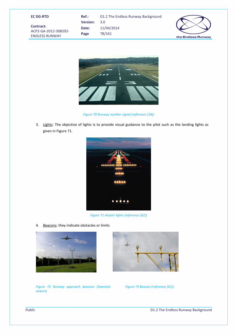
EC DG-RTD Contract: ACP2-GA-2012-308292- ENDLESS RUNWAY
Ref.: D1.2 The Endless Runway Background Version: 3.0
Date: 11/04/2014 Page 78/161
Public
D1.2 The Endless Runway Background
Figure 70 Runway number signal (reference [58])
3. Lights: The objective of lights is to provide visual guidance to the pilot such as the landing lights as
given in Figure 71.
Figure 71 Airport lights (reference [62])
4. Beacons: they indicate obstacles or limits
Figure 72 Runway approach beacons (Stansted airport)
Figure 73 Beacon (reference [61])
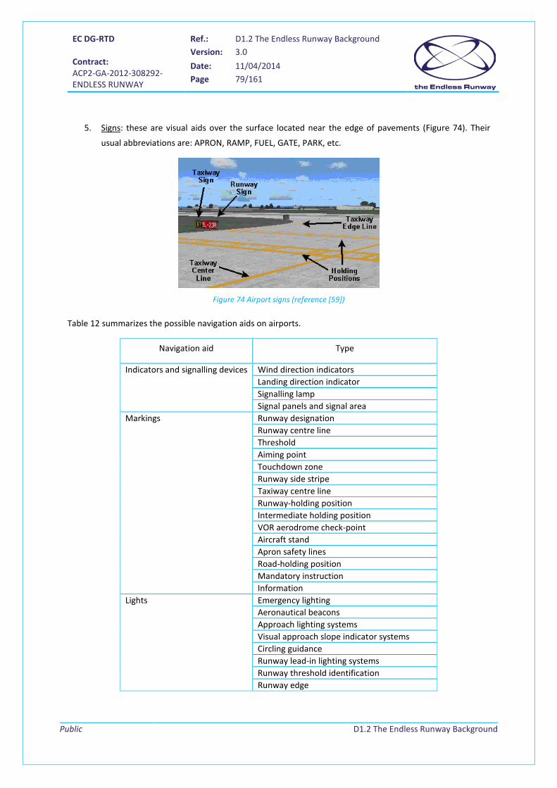
EC DG-RTD Contract: ACP2-GA-2012-308292- ENDLESS RUNWAY
Ref.: D1.2 The Endless Runway Background Version: 3.0
Date: 11/04/2014 Page 79/161
Public
D1.2 The Endless Runway Background
5. Signs: these are visual aids over the surface located near the edge of pavements (Figure 74). Their
usual abbreviations are: APRON, RAMP, FUEL, GATE, PARK, etc.
Figure 74 Airport signs (reference [59])
Table 12 summarizes the possible navigation aids on airports.
Navigation aid Type
Indicators and signalling devices Wind direction indicators Landing direction indicator Signalling lamp Signal panels and signal area
Markings Runway designation Runway centre line Threshold Aiming point Touchdown zone Runway side stripe Taxiway centre line Runway-holding position Intermediate holding position VOR aerodrome check-point Aircraft stand Apron safety lines Road-holding position Mandatory instruction Information
Lights Emergency lighting Aeronautical beacons Approach lighting systems Visual approach slope indicator systems Circling guidance Runway lead-in lighting systems Runway threshold identification Runway edge

EC DG-RTD Contract: ACP2-GA-2012-308292- ENDLESS RUNWAY
Ref.: D1.2 The Endless Runway Background Version: 3.0
Date: 11/04/2014 Page 80/161
Public
D1.2 The Endless Runway Background
Runway threshold and wing bar Runway end Runway centre line Runway touchdown zone Stopway Taxiway centre line Taxiway edge Stop bars Intermediate holding position De/anti-icing facility exit Runway guard Apron floodlighting Visual docking guidance Aircraft stand manoeuvring guidance lights Road-holding position light
Signs Mandatory instruction Information VOR aerodrome check-point Aerodrome identification Aircraft stand identification Road-holding position
Markers Unpaved runway edge Stopway edge Edge markers for snow-covered runways Taxiway edge Taxiway centre line Unpaved taxiway edge Boundary
Table 12 Airport visual navigation aids
5.4 Environmental and societal considerations Nowadays society is highly concerned about the environmental impact of airports. The growth of the main
cities around the world has led to an increase of the number of people exposed to airport environmental
Runway navigation visual aids will be an important aspect to consider when a circular runway will be
actually constructed. Some elements, like landing signals, will not be relevant as the aircraft can land
anywhere in the circle. Other elements will need reconsideration, e.g. beacons and the runway entry
sign that indicates the runway orientation. As the Endless Runway will have several entries, the
orientation will need to be indicated at the entry. Besides, as aircraft will certainly not take off in the
direction of the entry because it will accelerate over the circle for some time before taking off, a
digital signal showing the expected takeoff direction would be useful. The air traffic controller would
introduce certain aircraft parameters, such as MTW, aircraft model, etc., and this new visual aid
would calculate the takeoff direction.
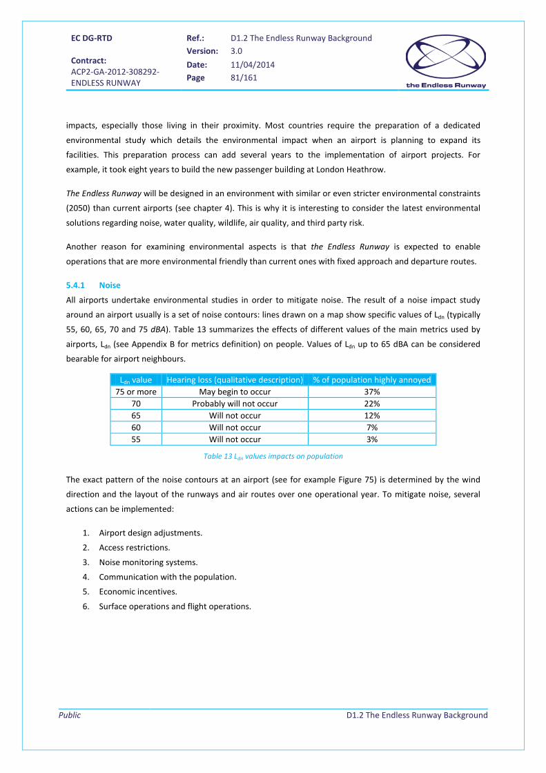
EC DG-RTD Contract: ACP2-GA-2012-308292- ENDLESS RUNWAY
Ref.: D1.2 The Endless Runway Background Version: 3.0
Date: 11/04/2014 Page 81/161
Public
D1.2 The Endless Runway Background
impacts, especially those living in their proximity. Most countries require the preparation of a dedicated
environmental study which details the environmental impact when an airport is planning to expand its
facilities. This preparation process can add several years to the implementation of airport projects. For
example, it took eight years to build the new passenger building at London Heathrow.
The Endless Runway will be designed in an environment with similar or even stricter environmental constraints
(2050) than current airports (see chapter 4). This is why it is interesting to consider the latest environmental
solutions regarding noise, water quality, wildlife, air quality, and third party risk.
Another reason for examining environmental aspects is that the Endless Runway is expected to enable
operations that are more environmental friendly than current ones with fixed approach and departure routes.
5.4.1 Noise
All airports undertake environmental studies in order to mitigate noise. The result of a noise impact study
around an airport usually is a set of noise contours: lines drawn on a map show specific values of Ldn (typically
55, 60, 65, 70 and 75 dBA). Table 13 summarizes the effects of different values of the main metrics used by
airports, Ldn (see Appendix B for metrics definition) on people. Values of Ldn up to 65 dBA can be considered
bearable for airport neighbours.
Ldn value Hearing loss (qualitative description) % of population highly annoyed 75 or more May begin to occur 37%
70 Probably will not occur 22% 65 Will not occur 12% 60 Will not occur 7% 55 Will not occur 3%
Table 13 Ldn values impacts on population
The exact pattern of the noise contours at an airport (see for example Figure 75) is determined by the wind
direction and the layout of the runways and air routes over one operational year. To mitigate noise, several
actions can be implemented:
1. Airport design adjustments.
2. Access restrictions.
3. Noise monitoring systems.
4. Communication with the population.
5. Economic incentives.
6. Surface operations and flight operations.

EC DG-RTD Contract: ACP2-GA-2012-308292- ENDLESS RUNWAY
Ref.: D1.2 The Endless Runway Background Version: 3.0
Date: 11/04/2014 Page 82/161
Public
D1.2 The Endless Runway Background
Figure 75 Noise contours at Amsterdam Airport Schiphol (source: NLR)
Airport design adjustments
Firstly, several airport design adjustments can be implemented in order to reduce noise. Runways can be
constructed so that the noise contours lead to as few as possible people experiencing nuisance. One source of
noise is the propagation of noise through the ground, which is depending on surface characteristics, as shown
on Figure 76.
Figure 76 Noise propagation through the ground (source: NLR)
Measures for noise reduction can be implemented in the ground infrastructure as well. The first option is
constructing well-placed high-speed runway exits that prevent the use of reverse thrust on landing. The
second one is the construction of new runways, taxiways, and buildings which are located further from

EC DG-RTD Contract: ACP2-GA-2012-308292- ENDLESS RUNWAY
Ref.: D1.2 The Endless Runway Background Version: 3.0
Date: 11/04/2014 Page 83/161
Public
D1.2 The Endless Runway Background
neighbouring communities. The third one is to put sound barriers, such as buildings or other structures at
strategic points at the airport periphery. For instance, Miami/International built a noise wall 669 meters long
and 6-9 meters high. Another example of a noise wall is depicted in Figure 77.
Figure 77 Inflatable noise wall proposed at Amsterdam Airport Schiphol (source: [63])
The fourth measure consists of displacing runway thresholds. This allows aircraft to fly over neighbouring
communities at a higher altitude both on approach and take-off.
Access restriction
By not allowing access to the airport to certain aircraft types or to restrain aircraft movements to specific times
of the day (preventing night operations), noise can be reduced. According to Annex 16 [27], an aircraft cannot
exceed certain levels of noise. Subsonic transport aircraft can be designated as Chapter 1, 2 and 3. Chapter 1
aircraft no longer operate in developed countries and chapter 2 aircraft have been phased out as of 1 April
2002 in the majority of developed countries. Therefore, nowadays fleets from developed countries should be
operating in Chapter 3.
Noise monitoring
Noise monitoring systems have become habitual for airports in developed countries. These consists of a series
of remote sensors/microphones (usually 10 or more) spread out at strategic points at the airport. The outputs
from sensors are transmitted to a central computing and reporting system. This computer also receives aircraft
operations data from the air traffic management system. Both noise and aircraft operations information is
correlated, so that aircraft producing excessive noise can be detected. Noise monitoring data can also be used
to improve noise estimation models.

EC DG-RTD Contract: ACP2-GA-2012-308292- ENDLESS RUNWAY
Ref.: D1.2 The Endless Runway Background Version: 3.0
Date: 11/04/2014 Page 84/161
Public
D1.2 The Endless Runway Background
Communication with population
Nuisance can be regulated by setting up a good communication with the population. Noise nuisance is a
subjective measure. Every individual will experience aircraft related noise in a different way. Every airport will
have a telephone or internet desk where noise complaints can be submitted. Most airports are looking for a
good relationship with their “neighbours” through informing them of measures they intend to take towards
avoiding noise nuisance and through agreements, which can be enforced through political measures.
Economic incentives
Economic incentives can be implemented, on one hand, noise-related landing fees and, on the other hand,
penalties for violating noise limits. The first incentive is effective in the long-term, as it motivates airlines to
purchase quiet aeroplanes. The second one can be considered a short-term incentive. A few major airports
have a system of fines for the airlines which deviate substantially from noise restrictions.
Operational restrictions
A growing number of airports are imposing measures in surface and flight operations in order to reduce noise.
Regarding surface operations, some airports restrict engine test-running and reverse-thrust during night-time.
Another possibility consists of limiting the number of taxiing aircraft, especially at times of air traffic
congestion. For flight operations, two measures can be adopted: noise reduction procedures on landing and
take-off and preferential runway systems. The first one consists of establishing arrival and departure flight
paths, STARs and SIDs, over uninhabited or less populated areas. New procedures, like Continuous Descent
Approaches (CDA) and Continuous Climbs (CC) are defined that will allow aircraft to perform more noise
and/or emissions friendly operations. Just as well, Performance Based Navigation (PBN) can be used to fly a
specified route more exactly, giving the possibility to avoid populated areas. In the second one, noise
abatement takes place thanks to an adequate runway choice, in other words, choosing runways in a way that
minimizes noise.
Noise considerations will be an important aspect, when developing the operational concept for the
Endless Runway. Noise contours will not follow the runway directions, but will go in any direction,
where the overall contour will reflect the yearly prevailing wind.
Contrary to current day noise considerations, people will not live “under” the arrival or departure
route, but anywhere near the airport, where aircraft can fly in and out.
One aspect is the land use of the airport operating an Endless Runway. As the airport will be smaller
in size, the noise footprint will be smaller as well. As the total generated noise will not decrease, the
noise volume will have a different shape with peaks all around the runway.
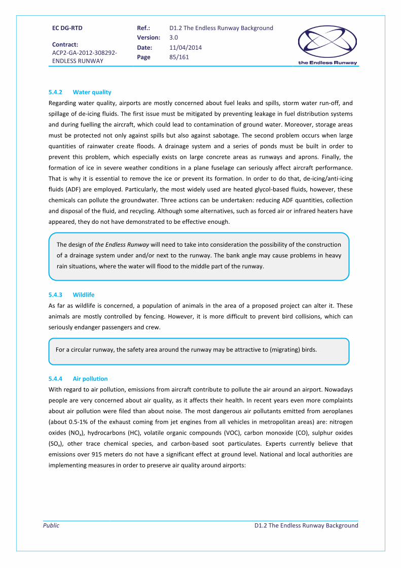
EC DG-RTD Contract: ACP2-GA-2012-308292- ENDLESS RUNWAY
Ref.: D1.2 The Endless Runway Background Version: 3.0
Date: 11/04/2014 Page 85/161
Public
D1.2 The Endless Runway Background
5.4.2 Water quality
Regarding water quality, airports are mostly concerned about fuel leaks and spills, storm water run-off, and
spillage of de-icing fluids. The first issue must be mitigated by preventing leakage in fuel distribution systems
and during fuelling the aircraft, which could lead to contamination of ground water. Moreover, storage areas
must be protected not only against spills but also against sabotage. The second problem occurs when large
quantities of rainwater create floods. A drainage system and a series of ponds must be built in order to
prevent this problem, which especially exists on large concrete areas as runways and aprons. Finally, the
formation of ice in severe weather conditions in a plane fuselage can seriously affect aircraft performance.
That is why it is essential to remove the ice or prevent its formation. In order to do that, de-icing/anti-icing
fluids (ADF) are employed. Particularly, the most widely used are heated glycol-based fluids, however, these
chemicals can pollute the groundwater. Three actions can be undertaken: reducing ADF quantities, collection
and disposal of the fluid, and recycling. Although some alternatives, such as forced air or infrared heaters have
appeared, they do not have demonstrated to be effective enough.
5.4.3 Wildlife
As far as wildlife is concerned, a population of animals in the area of a proposed project can alter it. These
animals are mostly controlled by fencing. However, it is more difficult to prevent bird collisions, which can
seriously endanger passengers and crew.
5.4.4 Air pollution
With regard to air pollution, emissions from aircraft contribute to pollute the air around an airport. Nowadays
people are very concerned about air quality, as it affects their health. In recent years even more complaints
about air pollution were filed than about noise. The most dangerous air pollutants emitted from aeroplanes
(about 0.5-1% of the exhaust coming from jet engines from all vehicles in metropolitan areas) are: nitrogen
oxides (NOx), hydrocarbons (HC), volatile organic compounds (VOC), carbon monoxide (CO), sulphur oxides
(SOx), other trace chemical species, and carbon-based soot particulates. Experts currently believe that
emissions over 915 meters do not have a significant effect at ground level. National and local authorities are
implementing measures in order to preserve air quality around airports:
The design of the Endless Runway will need to take into consideration the possibility of the construction
of a drainage system under and/or next to the runway. The bank angle may cause problems in heavy
rain situations, where the water will flood to the middle part of the runway.
For a circular runway, the safety area around the runway may be attractive to (migrating) birds.

EC DG-RTD Contract: ACP2-GA-2012-308292- ENDLESS RUNWAY
Ref.: D1.2 The Endless Runway Background Version: 3.0
Date: 11/04/2014 Page 86/161
Public
D1.2 The Endless Runway Background
• Firstly, by monitoring air quality at and around an airport.
• Secondly, by modifying aircraft operations, for example, through an airport design aimed at reducing
taxiing distances, reducing the use of APU units when the plane is next to the terminal, and through
installing central power units via passenger buildings. Finally, restrictions can be placed on engine run-
ups at night-time.
• Thirdly, a reduction of delays and aeroplanes taxiing can abate air pollution. The maximum departure
rate is reached at a certain number of aircraft taxiing out. Having more aeroplanes taxiing out, that
will have to wait in a long queue in front of the runway, only contributes to increased emissions.
• Finally, imposing emission-based landing fees has become another effective measure.
5.4.5 Third party risk
Third party risk is the probability that one person or that a group of persons permanently residing at a
particular location, suffers fatal injuries as a direct result of a single aircraft accident on or near its position. As
most accidents on conventional runways occur during take-off and landing (Figure 78), the areas just before
and after runways are the most sensitive for third parties. A further division of runway accidents is given in
Figure 79.
Figure 78 Percentage of fatal accidents by phase of flight (source: NLR)
Similar to the consideration made with noise, the air quality of the area around the airport will
significantly change (possibly more spread) with operations in all possible directions on the Endless
Runway. On the other hand, higher concentration of pollutants might be experienced at the center of
the circle due to concentrated taxiing operations and to the presence of the wall constituted by the
banked track.

EC DG-RTD Contract: ACP2-GA-2012-308292- ENDLESS RUNWAY
Ref.: D1.2 The Endless Runway Background Version: 3.0
Date: 11/04/2014 Page 87/161
Public
D1.2 The Endless Runway Background
Figure 79 Types of runway incidents and accidents (source: NLR)
To mitigate third party risk around airports, usually regulation exists that prevents communities, organisations,
or individuals to build real estate within high risk areas. These areas are defined based on risk models that
indicate the risk of fatal accidents per year at a certain location. In areas where this risk is 10-5 or higher, no
building activities are allowed at all; in areas where the risk is 10-6, only limited activities are allowed, e.g.
industrial activities, but definitely no schools or hospitals should be present. In several countries, like the
Netherlands, Germany, Great Britain, and Italy, regulations are enforced by law.
5.4.6 Future Environmental Aspects
As explained in 5.4, the growth of the main cities around the world has led to an increase of the number of
people exposed to airport noise, especially those living in the proximity of them.
Clean Sky European aeronautical research program [104] remarks that air transport's contribution to climate
change represents 2% of human-induced CO2 emissions (where the total of all transport sources contributes to
12%). All flights together produce 628,000,000 tonnes of CO2 yearly. Emissions will increase; it is estimated
In the Endless Runway, aircraft will not fly arrival and departure patterns, instead, they can operate
anywhere around the airport, leading to a significant change in the third party risk areas. Models will
need to be modified in order to enable calculations for circular runways.
Runway overshoots will not be possible any longer on an Endless Runway.
The risk of runway undershoots will still exist.
The risk of runway veer-off accidents will need to be investigated further. From the early trials on
banked circular runways, it showed that the increasing bank angle causes the aircraft to
“automatically” correct pilot errors for going too fast or too slow on a particular part of the track, so
that veer-off accidents to the outside of the circle might be reduced.
EC DG-RTD Contract: ACP2-GA-2012-308292- ENDLESS RUNWAY
Ref.: D1.2 The Endless Runway Background Version: 3.0
Date: 11/04/2014 Page 88/161
Public
D1.2 The Endless Runway Background
that the equivalent of 1,300 new international airports will be required worldwide by 2050 with a doubling in
the commercial aircraft fleet.
Therefore, the major aviation challenge is to meet the predicted growth in demand for air travel (increasing 4-
5% per annum over the next 20 years) but to do so in a way that ensures minimum impact on the
environment.
Aviation industry in Europe has long recognised this challenge. As a consequence, in 2001, the Advisory Council
for Aeronautical Research in Europe (ACARE) [67] established the following targets for 2020 (compared to
2000):
• Reduce fuel consumption and CO2 emissions by 50% per passenger kilometre • Reduce NOx emissions by 80% • Reduce perceived noise by 50% • Make substantial progress in reducing the environmental impact of the manufacture,
maintenance, and disposal of aircraft and related products
In addition, ACARE has identified the main contributors to achieving the above targets. The predicted
contributions to the 50% CO2 emissions reduction target are:
• Efficient aircraft: 20-25% • Efficient engines: 15-20% • Improved air traffic management: 5-10%
Going beyond these objectives and with 2020 now not far off in terms of civil aircraft development cycles
(typically 10 - 15 years), ACARE has been evaluating the progress towards the 2020 targets and conducted a
consultation process to identify priorities for a new vision for 2050 [73]. It is clear that these longer term
targets will be at least as demanding as the ACARE 2020 targets and it is widely accepted that to achieve these
longer term aims there will need to be a significant step change in the technologies of future aircraft as well as
operational changes.
According to [66], in 2050, it is envisaged that the effect of aviation on the atmosphere is fully understood. A
reduction on aviation’s impact on citizens and the environment is needed, and aviation has an important role
to play in reducing noise as well as greenhouse gas emissions, regardless of traffic growth. Biofuels and
hydrogen are gaining increased attention by factors as oil price increasing and concern over greenhouse gas
emissions from fossil fuels. This new generation of alternative fuels should be compatible with new generation
of aircraft and with those existing conventional aircraft.
The Endless Runway concept should take into account this alternative fuels, specially the Hydrogen, in
order to include specific safe facilities for its storage.

EC DG-RTD Contract: ACP2-GA-2012-308292- ENDLESS RUNWAY
Ref.: D1.2 The Endless Runway Background Version: 3.0
Date: 11/04/2014 Page 89/161
Public
D1.2 The Endless Runway Background
EREA ATS 2050 [65] presents as one of the principal challenges for future Air Transport the environment issue.
A dramatic reduction of chemical emissions (CO2, NOx) and perceived external noise is necessary. Using
alternative energies on both aircraft and ground support equipment could lead to a positive environmental
impact. Besides improving the air vehicles, new and intelligent ways of energy efficient and climate neutral
facility management concepts need to be implemented. With an efficient integration with intermodal
transport in place, some of the current environmental issues can be solved. The headline figure is the aim to
reduce carbon emissions generated by Europe’s transport system by 50% by 2050.
The Clean Sky program has recently published the Clean Sky Technology Evaluator [105], a tool that will help
inform the members and external stakeholders of the Clean Sky program and will help guide decisions for
future optimization of research efforts. Within this evaluator it is explained how to address airport
environmental concern. Noise nuisance and increasingly local air-quality issues are contained within the wider
airport surroundings.
Research in energy generation and storage is currently developed by several groups. The Aero-Loop concept
[41] for instance, tries to contribute to this environmental challenge by using the battery panels located under
the runway. These battery panels are intended to utilize the centrifugal force of the aircraft on the runway to
generate electricity.
5.5 Innovative Airport Concepts Aspects that have to be taken into account for airport design for the future are listed in ACARE, Strategic
Research Agenda, volume 2, 2004 [73], where it is noticed that step changes are needed in several areas,
amongst which:
• Advanced airport design to enhance efficiency and capacity, including advanced pavement.
• Ground transportation interfaces and integration.
• Aircraft ground movement management and optimization, including automatic taxiing and extension
of flight management to mission management (i.e. from gate-to-gate).
• Airport operations and maintenance:
o Next generation passenger, luggage and cargo systems - utilizing RFID (Radio-Frequency
Identification) and biometrics.
o Ticketing/boarding pass/immigration improvements.
• Aircraft integration and support services:
o Ground power.
o Fuel, food and waste.
The Endless Runway concept will have highly ambitious environmental goals when selecting the most
promising concept. Airport general layout should present benefits compared to conventional airport
layout with respect to aircraft noise and emissions.
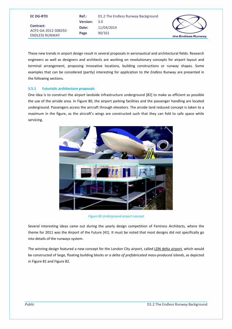
EC DG-RTD Contract: ACP2-GA-2012-308292- ENDLESS RUNWAY
Ref.: D1.2 The Endless Runway Background Version: 3.0
Date: 11/04/2014 Page 90/161
Public
D1.2 The Endless Runway Background
These new trends in airport design result in several proposals in aeronautical and architectural fields. Research
engineers as well as designers and architects are working on revolutionary concepts for airport layout and
terminal arrangement, proposing innovative locations, building constructions or runway shapes. Some
examples that can be considered (partly) interesting for application to the Endless Runway are presented in
the following sections.
5.5.1 Futuristic architecture proposals
One idea is to construct the airport landside infrastructure underground [82] to make as efficient as possible
the use of the airside area. In Figure 80, the airport parking facilities and the passenger handling are located
underground. Passengers access the aircraft through elevators. The airside land reduced concept is taken to a
maximum in the figure, as the aircraft’s wings are constructed such that they can fold to safe space while
servicing.
Figure 80 Underground airport concept
Several interesting ideas came out during the yearly design competition of Fentress Architects, where the
theme for 2011 was the Airport of the Future [41]. It must be noted that most designs did not specifically go
into details of the runways system.
The winning design featured a new concept for the London City airport, called LDN delta airport, which would
be constructed of large, floating building blocks or a delta of prefabricated mass-produced islands, as depicted
in Figure 81 and Figure 82.

EC DG-RTD Contract: ACP2-GA-2012-308292- ENDLESS RUNWAY
Ref.: D1.2 The Endless Runway Background Version: 3.0
Date: 11/04/2014 Page 91/161
Public
D1.2 The Endless Runway Background
Figure 81 Airport of building blocks
Figure 82 LDN Delta Airport, Oliver Andrew, London South Bank University
The LDN islands would be situated in the Thames Estuary, upstream from London. The airport would ease the
overcrowding of the surrounding airports as there are no cars, highways, nor check-in desks, since it is served
solely via public transportation. Flight information (including departure time and assigned gate) is provided

EC DG-RTD Contract: ACP2-GA-2012-308292- ENDLESS RUNWAY
Ref.: D1.2 The Endless Runway Background Version: 3.0
Date: 11/04/2014 Page 92/161
Public
D1.2 The Endless Runway Background
through passengers' cell phones. The airport supports vertical take-off with hypersonic jets capable of flying at
the edge of space, lifting off from purpose-built landing pads, and using the tidal currents to run on total
sustainable power.
The Aero-Loop’s concept (see Figure 83 and Figure 84) aims at creating an environmentally friendly platform
for future transportation which optimizes performance and energy consumption to achieve self-sustainability
while acquiring as minimal space as possible. The proposed runway is in the form of a continuous loop. Aircraft
move along the track for few rounds before lift-off/ landing, thus reducing land usage. In fact, this
revolutionary concept is in line with the Endless Runway concept.
Figure 83 Aero-Loop, Thor Yi Chun, University of Science of Malaysia
Figure 84: Aero loop take-off and landing concept

EC DG-RTD Contract: ACP2-GA-2012-308292- ENDLESS RUNWAY
Ref.: D1.2 The Endless Runway Background Version: 3.0
Date: 11/04/2014 Page 93/161
Public
D1.2 The Endless Runway Background
5.5.2 Airside and landside innovations
New technologies and revolutionary approaches for both airside and landside shall be implemented in order to
achieve the goals presented for the far future 2050, as presented in chapters 4 and 5.4.6.
New aircraft configurations, described in chapter 7 of this document, will probably require adaptations of
runway dimensions. Runway geometry can evolve to provide service under all wind conditions, as in the
Endless Runway concept.
New operations such as automatic taxiing and servicing will also influence the airport arrangement.
On the landside, a more passenger-oriented airport is envisaged to radically change the current terminals.
Finally, future transport intermodality will directly influence the interface between airport and other transport
means.
New airport designs shall help facing these challenges.
5.5.2.1 Airside innovations
With respect to the airport airside, apart from those characteristics related to number, orientation, and
configuration of runways as well as usual criteria used for airside design, other factors have to be taken into
account for future airports.
Section 5.1 and 5.2 explain that runways are designed based, amongst others, on expected traffic demand and
on environmental design considerations. As explained in [65], real or actual capacity is usually lower than
declared capacity because of weather restrictions and dependencies between runways. This is why current
trends in airport runway operations optimize the use of the existing runway system through:
• Improved planning resulting from SESAR trajectory-based operations.
• Increased use of noise abatement operations.
• Capacity increases from better understanding of wake-vortices, enabling reduced separation and new
approach procedures.
In order to avoid nuisance for inhabitants of surrounding communities and to safe space, new visions
regarding the location of runways and their orientation appear:
• Runways separated from the airport: remote runways, possibly in the sea.
• Large surfaces enabling runway operations from any direction.
• Double deck runways used for land use saving.
• Airports in the sky (cruiser – feeder concept).
• Design of a large circle as runway that would enable operations from any direction.
This latter idea is the one that is taken as a base for the development of the Endless Runway concept.

EC DG-RTD Contract: ACP2-GA-2012-308292- ENDLESS RUNWAY
Ref.: D1.2 The Endless Runway Background Version: 3.0
Date: 11/04/2014 Page 94/161
Public
D1.2 The Endless Runway Background
5.5.2.2 Landside innovations
The airport landside is not just the physical interface for passengers, baggage, and cargo between surface and
air transport. It is also the interface between the air transport service providers (airlines, airports etc.) and the
end users – the passengers.
As stated in [65], future landside infrastructure and services must focus on passenger’s needs and comfort.
This document also states that airport terminals in the future will be much less time-consuming for the
passenger. As time needed in processing steps and especially waiting time is perceived uncomfortable by the
users, those times should be reduced to a large extent. This could be achieved by reducing the number of
process steps or by changing their quality, duration, or even location. Automation and wireless technologies
will strongly support this development. The travel process will be hassle-free, smooth, and free of disruptions.
Terminals will be without queues as process steps, which need to remain at the airport, will develop to be
more sophisticated and provide more capacity. The time required for processes between arrival at the airport
and boarding the aircraft will not exceed 15 minutes for short-haul flights and 30 minutes for long-haul flights.
To achieve this, one very important area of development is the security check which nowadays often causes
too much hassle. Future systems will support a secure and thorough screening on the move without
interrupting the flow, ensuring full security with maximum freedom of movement together with minimal
intrusiveness.
Airport terminals will have short walking distances for passengers. Moving walkways and individual automated
guided vehicle systems will serve passengers to cover long distances conveniently and fast where needed – not
just between different terminals but also within large terminals. Baggage will be cared for at an earliest
possible stage. This might be via pick up services at home or at the hotel prior to departure as well as through
city center baggage drop off stations, baggage check-in in the train to the airport, or via postal / parcel
services. Baggage and passenger flow thus might be uncoupled to some extent. Also shopping might develop
into a more virtual direction where goods can be selected at home prior to travel or in the aircraft while flying
and delivery will be at the destination airport or even back at home via parcel services.
Regarding the Endless Runway concept, the terminal buildings are proposed to be constructed in the
centre of the circle, which leads to a more compact terminal that would reduce the space needed. In
addition, this would ease access to boarding areas reducing the distances for passengers and
consequently making the process less time consuming.
EC DG-RTD Contract: ACP2-GA-2012-308292- ENDLESS RUNWAY
Ref.: D1.2 The Endless Runway Background Version: 3.0
Date: 11/04/2014 Page 95/161
Public
D1.2 The Endless Runway Background
6 Background on ATM procedures This chapter provides information on ATM procedures and on the ATM system. The aim of air traffic control is
to organise and guide the traffic in the air and on ground. For The Endless Runway project, the most important
are the procedures around the runway.
The first part of the chapter gives an overview of the current TMA and airport operations. Starting with the
transition from the cruise phase, down to the final approach to the threshold with a possible go-around,
procedures and commonly used systems are described briefly. As the final approach to the Endless Runway
needs to be redesigned, additional attention is paid to the current situation here. In addition, some topics
relevant for actual developments that have direct relation to the Endless Runway are addressed.
The second part of the chapter is looking into the future of ATM. Short term initiatives from EUROCONTROL
and the CAA are mentioned as well as the main programme for the future ATM in Europe SESAR. New
concepts like 4D-trajectories and free flight are presented and some developments in systems highlighted.
Finally automation is looked at as this might become one of the most relevant part future air traffic, enabling
ATM actors to become managers rather than operators.
6.1 TMA and airports operations In the Terminal Manoeuvring Area (TMA) and Control Zone (CTR), aircraft climb and descent between the
airport surface and the air routes. Climbing and descending traffic, but also passing over flights, are safely
separated by air traffic control. ATC uses standard inbound (STARs) and outbound routes (SIDs), radar
vectoring, flight level separation, speed control, tromboning19, and procedures to separate traffic.
To assist the pilot in approaching the runway, special navigation equipment is available. The most commonly
used is ILS (Instrument Landing System), but alternatives are available using MLS (Microwave Landing System),
and GPS (Global Positioning System). Furthermore, modern navigation equipment also allows for precise
navigation throughout the TMA using RNAV (Area Navigation).
In terms of fuel consumption, the most efficient inbound and outbound trajectories are the Continuous
Descent Approach (CDA) and Continuous Climb Operations (CCO). In case an aircraft is not able to perform a
nominal landing, it has to perform a missed approach or balked20 landing. In case an aircraft has a non-nominal
departure the aircraft can choose to go-around and return to the airport.
Because of the very different layout of the Endless Runway it is expected that current operations, procedures
and systems might have to change. Therefore an overview on the relevant phases of arriving and departing
aircraft is given.
19 Tromboning consists of adjusting the moment an aircraft turns to base to intercept the final approach path. 20 A balked landing is a very late missed approach.

EC DG-RTD Contract: ACP2-GA-2012-308292- ENDLESS RUNWAY
Ref.: D1.2 The Endless Runway Background Version: 3.0
Date: 11/04/2014 Page 96/161
Public
D1.2 The Endless Runway Background
6.1.1 Descent and Climb Operations
Aircraft are assigned standard departure routes (SIDs) when taking off from a specific runway towards a
specific TMA exit point (see Figure 108). The exit points connect to the ATS routes. The SIDs allow the aircraft
to exit the TMA at the desired exit point and to climb without any further restrictions out of the TMA. The SIDs
are positioned mostly in such a way that aircraft are separated from other traffic flows including descending
traffic. The air traffic controller does not need to instruct the pilot about the specifics of the departure route to
follow, as all the waypoints are known for each specific SID. Aircraft following the same SID will need some
time separation as they could otherwise overtake each other. This time separation is normally provided by the
runway controller. The waypoints of a SID are linked directly to navigational beacons VORs/DMEs/NDBs or can
be based on virtual waypoints by applying RNAV.
Also, for the approach a pilot can use navigational beacons like VORs/DMEs/NDBs to navigate his or her
aircraft towards the final approach. The air traffic controller can actively separate inbound and outbound
traffic flows by using radar vectoring, flight level, and speed control. With radar vectoring, aircraft can be put
in the right sequence and separation between subsequent aircraft can be established very fast. The easiest
way of separating traffic is by using vertical separation. Indeed, by keeping traffic at different flight levels
aircraft can be separated safely without the need to precisely know the positions of aircraft in the TMA. For
aircraft following the same route, speed control is also used to control the separation between subsequent
aircraft. By coupling the speeds of subsequent aircraft, the controller ensures that aircraft will not overtake
each other. Furthermore, the approach controller can influence the time between subsequent aircraft on final
approach by adjusting the moment an aircraft is turning to base to intercept the final approach path. This is
called tromboning. Another alternative is the use of RNAV routes towards the final approach. These RNAV
routes are like SIDs separated from other inbound and outbound traffic flows. With RNAV routes the aircraft
can precisely calculate the optimal approach profile to the runway. This is not possible with radar vectoring
where the controller dictates the approach profile.
Coming from the cruise phase of flight on high altitude, aircraft start their descent towards the destination
airport. The optimal approach for a flight is the Continuous Descent Operation (CDO). During the CDO a flight
will make an approach using (near-)idle thrust setting, thereby saving fuel. At the ILS intercept altitude the
aircraft will level off, and intercept the ILS localizer signal and then the ILS glideslope. From that point on a
regular final approach is flown. The CDO complicates the TMA operations as the aircraft must be given more
freedom in their vertical profile. As a result of this controllers will increase separation between subsequent
aircraft. Consequently full CDOs are currently applied only in low capacity situations, for instance during night
operation. The counterpart of the CDO is the Continuous Climb Operation (CCO). Here the aircraft can choose
the optimal climb profile for a climb towards the ATS routes.
EC DG-RTD Contract: ACP2-GA-2012-308292- ENDLESS RUNWAY
Ref.: D1.2 The Endless Runway Background Version: 3.0
Date: 11/04/2014 Page 97/161
Public
D1.2 The Endless Runway Background
6.1.2 Final approach
The final approach allows the flight crew to align with the runway centreline and to stabilize the aircraft for
landing. For the latter, the aircraft must be configured with the corresponding landing configuration (flaps,
gear, etc.), and the corresponding landing speed.
The landing system will guide the aircraft to the touchdown point and even along the runway during the roll-
out phase. The most commonly used equipment for landing is the Instrument Landing System (ILS). An
alternative system is MLS (Microwave Landing System), which allows curved landing approaches, but MLS is
rarely available or used at airports. Another alternative is GPS which, in conjunction with a ground-based
augmentation (GBAS) or space-based augmentation (SBSAS) enables Cat I approaches.
6.1.2.1 Instrument Landing System (ILS)
The ILS has a glide path and localizer antenna and gives lateral and vertical guidance to the aircraft. Because of
the used technology a straight path to the threshold is defined which is typically around 10NM long and has a
glide path of 3° (see Appendix F, Figure 109).
As traffic will not follow the same routes to the Endless Runway the separation of traffic will be limited
to lateral and vertical separation. Speed control will not be necessary to separate traffic in the TMA.
The approach controller for the Endless Runway must have methods to separate the traffic correctly.
These methods must not necessarily be tromboning, and can take advantage of the circular nature of
the Endless Runway.
In the current TMA a CDO can be flown until the aircraft has intercepted the ILS. From that point on a
regular final approach is flown where the aircraft is stabilized for touchdown at a single touchdown
point. For the Endless Runway the touchdown point can be moved. Stabilizing for touchdown on the
Endless Runway can be expected to be easier as the touchdown point can be moved. Therefore a CDO
until touchdown can be considered for the Endless Runway.
The landing navigation systems ILS and MLS are geared towards singular touchdown points. For the
Endless Runway a landing navigation system will be needed that is not fixed to this single touchdown
point. It is therefore recommended to have a landing navigation system that is independent from the
chosen touchdown point, and that can handle all visibility conditions. Currently, such a landing
navigation system is not available, but we expect that future Satellite Navigation Systems with local
area augmentation can provide the needed flexibility, reliability, and accuracy.

EC DG-RTD Contract: ACP2-GA-2012-308292- ENDLESS RUNWAY
Ref.: D1.2 The Endless Runway Background Version: 3.0
Date: 11/04/2014 Page 98/161
Public
D1.2 The Endless Runway Background
Lateral Guidance
Vertical Guidance
Final Approach PathGlide Path Antenna
Localizer Antenna
Figure 85 ILS systematic view
Dependent on the technical equipment (ground and on-board) and the skills of the air crew it can be applied
even up to zero visibility conditions using an automatic landing system, based on radio signals. The system is
categorized by:
Category Minimum Decision Height (DH)
Minimum Runway Visual Range (RVR)
Visibility
I 60m (200 feet) 550m 800m
II 30m (100 feet) 350m
IIIA 30m (100 feet) 200m
IIIB 15m (50 feet) 50m
IIIC No DH Limitation No RVR Limitation
Table 14 ILS categories ([106])
Besides a marker beacon, which is often used as an additional checkpoint during the approach, large airports
provide a medium- or high-intensity approach light systems to allow operations in almost all visibility
conditions. The lights support the transition from the instrument phase to the visual phase, where the pilot
aligns the aircraft with the runway centreline.
6.1.2.2 Microwave Landing System (MLS)
The Microwave Landing System is more advanced than the ILS and was intended to replace it. It has some clear
advantages over ILS that are (in some cases) also relevant for the Endless Runway:
For the Endless Runway ILS procedures are not applicable anymore. Curved approaches are needed
which cannot be supported by the ILS system. Even more, the dynamical definition of touchdown
points makes it almost impossible to provide the relevant radio signals and visual guidance.

EC DG-RTD Contract: ACP2-GA-2012-308292- ENDLESS RUNWAY
Ref.: D1.2 The Endless Runway Background Version: 3.0
Date: 11/04/2014 Page 99/161
Public
D1.2 The Endless Runway Background
• Antennas are much smaller
• They can be placed anywhere in the airport area and the signal will be corrected electronically
(ILS localizer generally has to be at the end of the runway)
• Uses only one frequency for different signals (congestion of the available frequencies was minimized)
• Improved accuracy
• The system covers a wider approach area (lateral and vertical)
• Smaller protection (critical and sensitive) areas
Slow Aircraft Approach
Curved Approach
High Speed Approach
Segmented Approach
Runway
Streching Approach
Figure 86 MLS approach with path stretching
However, ILS is still the most commonly used navigation aid for Cat I/II/III conditions. FAA opted long ago for
GPS augmented solutions to replace ILS. MLS is installed at some European airports (e.g. London Heathrow), in
conjunction with existing ILS, but few aircraft are equipped with a Multi-Mode Receiver required to use MLS.
Considering its advantages and capabilities, MLS could be a suitable landing system to be used in
conjunction with an Endless Runway. However, aircraft equipped with MLS remain scarce.

EC DG-RTD Contract: ACP2-GA-2012-308292- ENDLESS RUNWAY
Ref.: D1.2 The Endless Runway Background Version: 3.0
Date: 11/04/2014 Page 100/161
Public
D1.2 The Endless Runway Background
6.1.2.3 Ground Based Augmentation Systems (GBAS)
With the availability of satellite based navigation solutions, navigational ground infrastructure is becoming less
important. The Global navigation Satellite System (GNSS) uses positioning satellites each of them sending their
current position and time information. Any receiver of these signals that has information of at least four
satellites can calculate its 3D position. GBAS is being developed (currently only Cat I capability is commercially
available) was to eventually cater for all weather operations, i.e. up to Cat III conditions. For GBAS, the
correction signals are transmitted by a ground station hence ground-based augmentation.
Figure 87 GBAS system principle
Besides the additional position and correction data, the ground station sends predefined approach paths to
the aircraft. Therefore, topographic limitations are a lesser problem as compared to ILS. GPS based systems do
not have a sensitive areas which is an important advantage over ILS and MLS systems where aircraft are not
allowed to be present in these areas during the final approach of subsequent aircraft. On the other hand
GNSS-based systems are more susceptible to radio interference and (un-)intentional jamming.
6.1.3 Operating constraints for take-off and landing
This chapter summarizes constraints that need to be considered when defining the Endless Runway concept
and procedures. This list is not exhaustive, additional constraints may be found when working on specific
thematic areas in the course of the project.
GBAS could be one of the enablers for the landing procedure to the Endless Runway.

EC DG-RTD Contract: ACP2-GA-2012-308292- ENDLESS RUNWAY
Ref.: D1.2 The Endless Runway Background Version: 3.0
Date: 11/04/2014 Page 101/161
Public
D1.2 The Endless Runway Background
6.1.3.1 Landing load and vertical speed
Some constraints due to airworthiness standards need to be taken into account when designing the operations
on the circular runway. In FAR 25.473 (Structural design limitations for landing gear, large aircraft), §25.473
“Landing load conditions and assumptions”, it is mentioned that: “For the landing conditions […] the aircraft is
assumed to contact the ground […] with a limit descent velocity of 10 fps at the design landing weight (the
maximum weight for landing conditions at maximum descent velocity), and with a limit descent velocity of 6
fps at the design take-off weight (the maximum weight for landing conditions at a reduced descent velocity).”
6.1.3.2 Low visibility conditions
Low visibility conditions reduce the runway capacity, according to local criteria and the availability of ILS
equipment. Low visibility conditions are divided into different categories, like the conditions given in Table 15
as applicable for Amsterdam Airport Schiphol (LVC = Low Visibility Conditions; RVR = Runway Visual Range):
Visibility condition Criteria CAVOK (Cloud And Visibility OK) >= 5000m
Marginal visibility visibility < 5000 m and/or cloud base < 305 m LVC phase A 550 m <= RVR <= 1500 m and/or 61 m <= cloud base <= 91 m LVC phase B 350 m <= RVR < 550 m and/or cloud base < 61 m LVC phase C 200 <= RVR < 350 m
LVC phase C+D possibility of RVR < 200 m
Table 15 Low visibility conditions
Marginal visibility and LVC limit the runway operations in such a way that no intersection take-offs are
allowed, runway crossings are avoided as much as possible, non-essential traffic is not allowed, combinations
of crossing runways is avoided, and separation is increased.
6.1.3.3 Wind limitations
Weather aspects that have an influence on runway operations are first of all the wind speed and direction.
Limitations on head wind and crosswind conditions are defined in accordance to local procedures as
recommended according to the information provided in [26], paragraph 3.1.3:
These vertical speed limits should be considered when designing the Endless Runway specific
procedures.
Low Visibility Conditions will have to be considered when describing the concept of operations of the
Endless Runway.

EC DG-RTD Contract: ACP2-GA-2012-308292- ENDLESS RUNWAY
Ref.: D1.2 The Endless Runway Background Version: 3.0
Date: 11/04/2014 Page 102/161
Public
D1.2 The Endless Runway Background
Landing or take-off is, in normal circumstances, precluded when crosswind component exceeds:
• 37 km/h (20 kt) for aeroplanes with reference field length >1500m except when poor runway braking
action owing to an insufficient longitudinal coefficient of friction is experienced with some frequency,
in which case the maximum crosswind component is 24 km/h (13 kt).
• 24 km/h (13 kt) for aeroplanes with reference field length between 1200m and 1500m.
• 19 km/h (10 kt) for aeroplanes with reference field length <1200m
6.1.4 Missed approach /Go-around
In case of traffic conflicts or because of non-optimal landing conditions, a pilot or controller can decide to
perform a missed approach or even a balked landing. The pilot will not land, but continue the flight along the
runway centre line climbing to the Missed Approach altitude. There, the pilot will follow a standard route
towards an approach fix, or will be vectored by the approach controller for a new approach. A missed
approach procedure can even be applied after the aircraft has touched the runway. This is called a go-around.
6.1.5 Vertical takeoff and landing
In 2050 it is expected, that vertical takeoff and landing procedures are in place for new types of air vehicles.
Besides the helicopters a number of new personal air transport vehicles that do not need long runways to
take-off and land will be available. With an increasing number of these vehicles and of the corresponding
number of flights, special procedures need to be developed to ensure a safe operation.
Implementing curved approach and departure profiles leads to more complexity when integrating vertical
operating vehicles. While it is relatively easy to separate them from the normal traffic nowadays (because of
the straight finals) approach paths will cross much more in the future.
This may impact the radius of the circular runway; the higher it will be, the less high crosswinds may
occur during landing or take-off. Computations taking into account the wind speed range, landing and
take-off distances, and runway radius, will be necessary to optimize the design of the Endless Runway.
In relation to the Endless Runway project this will be an important issue to consider. Aircraft make
missed approaches at current runways due to being not stable for the landing, mechanical issues or
due to other traffic. For the Endless Runway missed approaches can still be expected. So for the
Endless Runway new missed approach procedures must be designed. This missed approach procedure
could take advantage of the circular nature of the runway.

EC DG-RTD Contract: ACP2-GA-2012-308292- ENDLESS RUNWAY
Ref.: D1.2 The Endless Runway Background Version: 3.0
Date: 11/04/2014 Page 103/161
Public
D1.2 The Endless Runway Background
6.1.6 Performance based navigation (PBN)
Performance based navigation (PBN) is one of the enablers for future ATM concepts and can offer operational
benefits in terms of capacity, flight efficiency and environment (noise). With PBN, there will be a shift from the
sensor-based to a performance-based navigation. PBN specifies that aircraft systems performance
requirements have to be defined in terms of accuracy, integrity, availability, continuity, and functionality
required for the proposed operations.
The first step was the implementation of Area Navigation (RNAV), where aircraft have on board systems that
can calculate any course between two points. With RNAV procedures there is no need to fly over ground based
navigational aids. Since RNAV uses predefined waypoints to define a route it enables flexibility in designing
routes thus it allows to optimise airspace usage (e.g. RNAV approach chart Appendix F Figure 110). PBN
prescribes so-called navigation specifications for each phase of flight. For RNAV5 the aircraft should remain
within +/- 5 NM of the intended flight path (and for RNAV1 this is +/- 1 NM for 95% of the flight time.
PBN specificies two categories: RNAV and RNP. In addition to RNAV systems that can achieve the required
accuracy, RNP systems also provide on-board performance monitoring and alerting. With these improvements
of integrity, closer routing and spacing is possible. With the naming convention of RNP the required
performance specification for procedures or airspace sectors is described.
For the approach phase (initial to final or even missed approach) A-RNP and RNP APCH have been defined with
a required accuracy of 1NM for all phases and 0.3 NM for the final approach segment. A special category called
RNP AR APCH (authorization required) is defined in the ICAO DOC 9913 (Manual on Performance Based
Navigation).
Within RNP APCH two subcategories are defined (see figure below) depending on whether vertical guidance is
provided or not. These are non-precision (2D) and approach with vertical guidance (3D) called APV.
The Endless Runway has to take vertical take offs and landings into account and allow these types of
operation on the airport.

EC DG-RTD Contract: ACP2-GA-2012-308292- ENDLESS RUNWAY
Ref.: D1.2 The Endless Runway Background Version: 3.0
Date: 11/04/2014 Page 104/161
Public
D1.2 The Endless Runway Background
Vertical requirements differ depending on the type of approach and required landing minima. For so-called
APV-I operations the navigation system should be able to provide a vertical navigation accuracy of at least 20
metres. For ILS Cat I, a vertical accuracy of at least 6 metres is required. A detailed description on the limits on
this procedure can be found in [108].
In [102] a timeline is described for the gradual transition towards full PBN operations. As presented in Figure
88 this transition should be finished in 2025.

EC DG-RTD Contract: ACP2-GA-2012-308292- ENDLESS RUNWAY
Ref.: D1.2 The Endless Runway Background Version: 3.0
Date: 11/04/2014 Page 105/161
Public
D1.2 The Endless Runway Background
Figure 88 Timeline for transitioning to PBN / RNP operations [102]
6.1.7 Multiple/flexible threshold operations
With direct relation to the Endless Runway the use of multiple/flexible thresholds was also identified by [72].
In the nearer future this might be related to conventional runway layouts in combination with short takeoff
and landing procedures or multiple approach angles and the use of more than one threshold on one runway.
In a first trial phase a system was implemented in Frankfurt between 1999 and 2004 with an additional
displaced threshold on runway 25L. The new threshold was called 26L and was set up about 1.500m from the
original 25L threshold. With the also existing parallel runway 25R, three thresholds were available. A full
approach lighting system was installed for threshold 26l also.
In relation to the Endless Runway, performance based navigation and in particular RNP AR APCH could
be the basis to enable approach and potentially landing operations on the circular runway. At the
moment, ICAO PANS-OPS requirements (Doc 8168) for instrument flight procedures do not cater for
non-straight runways. Low visibility operations (Cat I) would require SBAS (e.g. EGNOS/WAAS) and
GBAS is expected to achieve Cat II/III operational capability within 5 years.

EC DG-RTD Contract: ACP2-GA-2012-308292- ENDLESS RUNWAY
Ref.: D1.2 The Endless Runway Background Version: 3.0
Date: 11/04/2014 Page 106/161
Public
D1.2 The Endless Runway Background
Figure 89 HALS/DTOP system at Frankfurt airport
In combination with this a new procedure called HALS/DTOP was introduced and tested. The first phase HALS
(high approach landing system) was using runway 25R and 26L and was intended to familiarize the pilots and
controllers with the operations. In the second phase DTOP (Dual Threshold Operation), all three thresholds of
the two runways were operational. The main focus on this operation was to avoid wake vortexes because of
the different approach paths and therefore a capacity gain. After a number of trials the system was removed
completely. The expected benefits could not be achieved and the workload for pilots and controllers was
slightly higher. Even if the system is not operational anymore, it showed that multiple thresholds are possible
on straight runways also.
6.2 Future ATM system There are two major programs in place for the definition of the future in ATM. While the NextGen programme
is concentrating on the US, the main initiative for the future ATM in Europe is the Single European Sky ATM
Research Programme (SESAR). As both are developing new standards in parallel, an agreement on
interoperability was reached by the European and American authorities.
6.2.1 Initiatives
This section provides an overview of programs for the modernization of the air transport system.
For the Endless Runway, using multiple thresholds is essential and one of the most beneficial points.
With only one resource available a high capacity can only be achieved with flexible touchdown and
departure points and simultaneous operations on the circle.

EC DG-RTD Contract: ACP2-GA-2012-308292- ENDLESS RUNWAY
Ref.: D1.2 The Endless Runway Background Version: 3.0
Date: 11/04/2014 Page 107/161
Public
D1.2 The Endless Runway Background
6.2.1.1 SESAR
The SESAR (Single European Sky ATM Research) programme has the goal of modernising the European Air
Traffic Management. Launched by the European Community it will combine technological, operational as well
as economic and regulatory aspects to harmonize and coordinate all relevant research and development
activities.
Based on the Single European Sky (SES) legislation it is intended to tackle safety and capacity needs but also
look for environmental and financial issues of the future ATM system.
One of the main achievements is the cooperation and involvement of all stakeholders in ATM. Separated into
Consortium Members and associated partners this includes Industry, Airspace Users, Air Navigation Service
Providers (ANSPs), Airport Operators and the Supply Industry (European and non-European), safety regulators,
military organisations, staff associations (including pilots, controllers and engineers) and research centres and
EUROCONTROL.
SESAR is separated in three phases
• Definition phase (2004-2008):
ATM master plan defining the content, the development and deployment plans of the next
generation of ATM systems.
• Development phase (2008-2013):
Produces the required new generation of technological systems and components as defined in the
definition phase.
• Deployment phase (2014-2020):
Large-scale production and implementation of the new air traffic management infrastructure.
As SESAR is setting the standards and technologies for the next years it has to be taken into account when
defining the concept for the Endless Runway. Some of the needs and technological changes already identified
by SESAR are directly related to the Endless Runway.
Already in the near future there will be significant changes in the general operation within the ATM system. In
SESAR [76] it is stated that:
“The ATM Concept of Operations for 2020 represents a paradigm shift from an airspace based
environment to a trajectory-based environment”.
Following this, the Endless Runway-concept will go even further and needs to adapt and extend some of the
already identified changes in operation and structures.
The following changes of ATM operation are already addressed by SESAR and might be relevant for the Endless
Runway.

EC DG-RTD Contract: ACP2-GA-2012-308292- ENDLESS RUNWAY
Ref.: D1.2 The Endless Runway Background Version: 3.0
Date: 11/04/2014 Page 108/161
Public
D1.2 The Endless Runway Background
• Trajectory Management - introducing a new approach to airspace design and management
• Collaborative planning continuously reflected in the Network Operations Plan
• Integrated Airport operations contributing to capacity gains
• New separation modes to allow for increased capacity
• System Wide Information Management – integrating all ATM business related data
• Humans central in the future European ATM system as managers and decision makers
6.2.1.2 CAA/UK Airspace of tomorrow
Taking SESAR as a base the CAA already defined in much more detail the future airspace for the UK. Within
[79], [80] and [81] a modernized airspace concept is presented with clear steps in concepts and technology
development to cope with the expected need of change. Even if this is prepared specifically for the UK, most of
the issues are similar in the rest of Europe and even in the US.
In relation to the expected benefits a number of potential technologies and concepts are setup in [80], see
Figure 90.
The Endless Runway concept for 2050 will need to extend the concept of a more flexible airspace,
which is already foreseen enroute, also to the approach and departure routes and to the use of the
airport ground resources (runway and taxiway system).
As the Endless Runway could lead to a more complex (simultaneous) use of resources a much more
intense collaborative planning might be necessary.
Optimised wind operations and flexible routing can lead to significant capacity gains and reduced
environmental problems. While conventional runways have to be closed in certain crosswind
conditions, the Endless Runway can provide at least two take-off and touchdown points and hereby a
minimum number of flights.
Complete new ways of separation have to be in place. As lateral spacing might not be relevant
anymore (no straight approach paths), safe ways of staggered separation with free choice of routing
and curved paths will have to be possible.
The role of ATC controllers is expected to change even more as the complexity of the Endless Runway
might lead to a work-overload. Therefore humans might be even more responsible for managing and
supervising the operation instead of actively control airspace users.

EC DG-RTD Contract: ACP2-GA-2012-308292- ENDLESS RUNWAY
Ref.: D1.2 The Endless Runway Background Version: 3.0
Date: 11/04/2014 Page 109/161
Public
D1.2 The Endless Runway Background
Figure 90 Potential technologies and concept for the UK Airspace in 2030 [80]
6.2.1.3 Strategic Research Agenda SRA
Looking into the Strategic Research Agenda 2 (SRA2) [72], a number of research fields seem to be relevant for
the future transport system. Based on the High Level Target Concept (HLTC) and the sector a tabular form
presents technologies that are proposed for the future. In relation to Airport and Air Traffic Management
(including the airspace around airports) the following elements can be found describing new structures,
systems, and procedures.
• Dynamic and collaborative (civil and military) airspace management, strategic and collaborative traffic
allocation
• Self-separated take offs and landing.
• Multiple/flexible threshold operations.
• Aircraft/VTOL simultaneous non interfering approaches and departures
• New runway management systems.
• Overarching airport management system (capacity, arrival, etc.)
Some of the mentioned technologies in the Strategic Research Agenda will be relevant for application to
the Endless Runway.
EC DG-RTD Contract: ACP2-GA-2012-308292- ENDLESS RUNWAY
Ref.: D1.2 The Endless Runway Background Version: 3.0
Date: 11/04/2014 Page 110/161
Public
D1.2 The Endless Runway Background
6.2.1.4 ACARE Vision 2050
In 2000 a European Vision on Air Transport to the year 2020 was launched by the European Commission.
ACARE, which was formatted on this base, produced 2 SRAs and an ADDENDUM: 2008 which provided major
challenges and High level targets. With new and even bigger challenges in the future a need for a new vision
beyond 2020 was identified. Therefore ACARE setup the “AERONAUTICS AND AIR TRANSPORT: BEYOND VISION
2020 (TOWARDS 2050)” [73]. Aspects of Society, Economy, Environment but also technology and operation are
addressed in the vision. Besides others some key ATM concepts and capabilities are mentioned that need to be
developed:
• 4D planning and flight execution to fully manage and optimise aircraft mission in time and space.
• Increased aircraft autonomy through topics such as airborne self-separation, to enable aircraft to
effectively interact with other aircraft
• Enhanced airspace management to maximise the efficiency and availability of airspace.
• The role of the human operator will be critical for a period, but in the timeframe under review it is
likely that automation will take over and enhance safety, performance and cost, subject to major
issues of social acceptance and technology.
• Key enablers will need to be developed in the fields of communication, navigation and surveillance.
6.2.2 Airspace structures
Because of the anticipated continuous growth of air travel (see 4.1), the current airspace structures could be
the limiting factor to reach the strategic goals of the visions for 2050. To overcome these restrictions the
future airspace is expected to be different from today. There will be a change from the rigid route structure
system of today towards a more flexible use of the available airspace resources. There are already some new
short and medium timeframe concepts developed to restructure the airspace especially in very congested
areas as Europe or the US.
EUROCONTROL introduced the “The 2015 Airspace concept & Strategy for the ECAC Area & Key Enablers” [83]
which describes an intermediate step for the near future in line with the SESAR ATM Target concept for 2020+.
With more complexity and diversity of future aircraft types (see chapter 7) a much more flexible and adaptable
airspace is envisaged to meet the most important requirements in terms of safety, capacity, efficiency, and
environmental aspects. According to the concept the airspace will be used on the basis of defined
performance targets that respect these requirements. Because of the dependencies between them a tradeoff
has to be found. This will result in a strategy of the configuration and use of the airspace which is defined in
[83] as an airspace configuration. It is stated that the changes are not only limited to en-route (ATS routes and
ATC sectors) but also to the terminal area and the overall management of the airspace. Therefore four streams
Some of the mentioned technologies in the ACARE Vision 2050 are relevant for application to the Endless
Runway.
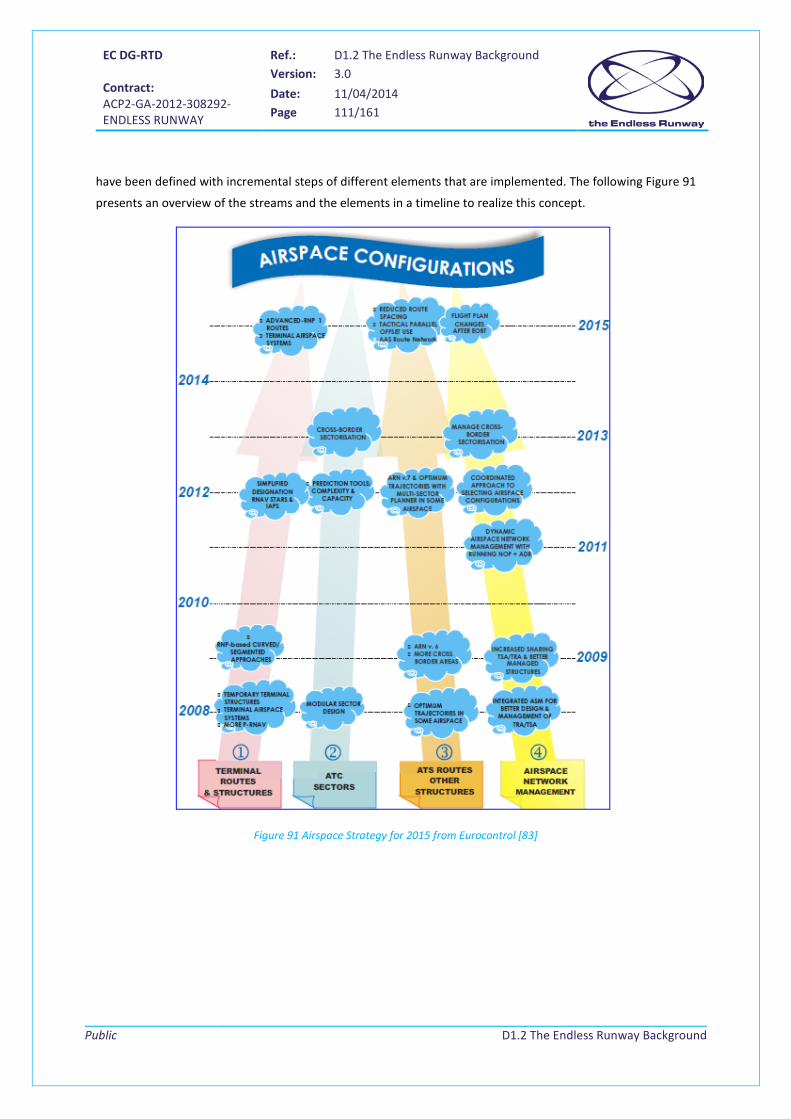
EC DG-RTD Contract: ACP2-GA-2012-308292- ENDLESS RUNWAY
Ref.: D1.2 The Endless Runway Background Version: 3.0
Date: 11/04/2014 Page 111/161
Public
D1.2 The Endless Runway Background
have been defined with incremental steps of different elements that are implemented. The following Figure 91
presents an overview of the streams and the elements in a timeline to realize this concept.
Figure 91 Airspace Strategy for 2015 from Eurocontrol [83]
EC DG-RTD Contract: ACP2-GA-2012-308292- ENDLESS RUNWAY
Ref.: D1.2 The Endless Runway Background Version: 3.0
Date: 11/04/2014 Page 112/161
Public
D1.2 The Endless Runway Background
6.2.2.1 4D-Trajectories
One of the key elements in the future transport is the implementation of a full 4D-operation. That means that
there will be a 4D-trajectory in place for each flight, which replaces the current ICAO flight plan structures.
Besides the three spatial dimensions, time is included as the fourth.
One of the problems with a 4D-trajectory is the missing capability to ensure the compliance of the aircraft to
its trajectory from the ground. In today’s environment, airborne and ground systems use trajectory data for
different purposes (flight plan vs. support tools), which leads to discrepancies in the trajectory. Those are
solved in the tactical phase between the air crew and the controllers. To overcome these problems, the
advanced 4D-contract concept introduces the idea that the responsibility of the compliance is transferred from
the ground to the aircraft.
A 4D-contract can be represented as a time dimension moving along with a three-dimensional airspace tube
assigned to each aircraft by the ATM system and/or negotiated by the aircraft themselves. All aircraft must
stay within their assigned 4D-volumes (i.e. respect their contracts) for the entire duration of the flight, so that
they are free of conflicts with other aircraft. If this is not possible, a new 4D-contract has to be negotiated.
During all phases of a flight, information about actual and planned positions in space and time are available
and exchanged with all concerned air and ground systems. This opens the possibility of coordinating flights and
negotiating flight profiles between airspace users and air traffic management leading to more predictability
and optimised usage of the available resources. One of the key issues will be to ensure safety with this new
approach of operation. Not only high accurate planning will be needed but also the capability of the respective
systems to follow the coordinated profile. Therefore big evolution in automation and flight management
systems is needed.
The 4D-contract is one of the main pillars of the SESAR program, which is currently implemented and will see
its implementation as of 2020. In the early application of the program, probably concessions will need to be
made with respect to full implementation of the 4D-contract, specifically in phases of the flight where
In stream 1 “Terminal Routes & Structures“, the following elements are mentioned that have a very
close relation to the Endless Runway project already. The concept can build on these steps that
should be in place in the near to mid-term future:
• Flexible Terminal Airspace Systems
• Flexible Placement of Terminal routes
• P-RNAV Temporary Terminal structures
• Enhanced navigation performance

EC DG-RTD Contract: ACP2-GA-2012-308292- ENDLESS RUNWAY
Ref.: D1.2 The Endless Runway Background Version: 3.0
Date: 11/04/2014 Page 113/161
Public
D1.2 The Endless Runway Background
sequences of aircraft need to be made under high demand (arrival management, departure management) and
tactical intervention cannot always be avoided.
6.2.2.2 Free Flight / Self-separation
"Free Flight" is defined in [77]:
"... as a safe and efficient flight operating capability under instrument flight rules in which the operators have
greater flexibility in selecting their path and speed. Air traffic restrictions are limited in extent and duration and
are only imposed to ensure separation, to preclude exceeding airport capacity, and to prevent unauthorized
flight through special use airspace".
Free Flight defines a concept where airspace users are not restricted to fixed routes and airway systems but
can choose their route themselves. This includes direct routing from departure to destination, the choice of
altitudes and speeds, and even considerations on weather and other hazards. Expectations are that the
concept leads to much more capacity in the airspace system. The main focus of the work in this area was the
en-route phase and originally addressed to low density traffic. In [78] an approach was taken to show that the
implementation of a free flight concept is also possible in a high density environment. Different simulations
showed that “…the distributed Free Flight ATM concept features a safety and airspace capacity that is
magnitudes higher than the current en-route ATM system…”. Looking into 2050 and taking [78] as a base, the
free flight concept could be implemented in the whole airspace also including very high density areas around
airports.
One of the key factors of the free-flight-concept is the transfer of responsibilities from air traffic controllers to
the airborne side. The role of the air traffic controller would change to safety monitoring and managing too
crowded airspace. Therefore concepts of self-separation were introduced where the aircraft is responsible to
maintain the minimum separation according to the regulations. The actual concept defines a protected zone
(that should never be penetrated) and an alert zone (when penetrated interventions and action are required).
With respect to the Endless Runway the 4D-trajectory concept needs to be in place to fully
coordinate airport operations. It will be necessary to agree on the usage of the runway in real time
with highly accurate information about the planned approach/departure path, touchdown points
and runway entry/exit operation to utilize the resources on a maximum.
Application of the full 4D-contract to the Endless Runway implies that the complete flight is planned
in advance and that the exact moment of take-off and landing is known some time before the flight
(or before the event actually happens – longer flights may be planned for landing while they are
already airborne). This implies that the take-off and touch down points need to be known in
advance.

EC DG-RTD Contract: ACP2-GA-2012-308292- ENDLESS RUNWAY
Ref.: D1.2 The Endless Runway Background Version: 3.0
Date: 11/04/2014 Page 114/161
Public
D1.2 The Endless Runway Background
Advanced airborne self-separation systems will include detection, prevention, and solution of potential conflict
situations.
Based on the expected growth of the number of movements and the increased complexity of the operations
the traffic has to be a kind of self-coordinated. The concept of free flight and self-separation will be extended
to the critical phases of takeoff and landing. With the availability of high performance networks and the
concept of 4D-contracts, coordination between the airspace users is possible. This leads to highly dynamic
lateral and vertical flight paths that have to be followed very precisely. One of the main challenges will be the
coordination between different types of airspace users, different approach and takeoff procedures, and
profiles.
6.2.2.3 Non controlled airspace
In terms of future airspace and air traffic control, different possibilities are conceivable.
It is envisaged that there will be much more unscheduled traffic in the future. Personal air transport (PAT),
business charters, or even unmanned aircraft systems (UAS) are part of the system with non-scheduled flight-
plans and no trajectory information available. Define special airspace dedicated to these operations is contrary
to the goal of using and optimizing the airspace as a whole. Numerous non-scheduled operations would
actually lead to an uncontrolled airspace with monitored and controlled areas. To allow safe operation under
these circumstances, all air vehicles will need to be equipped with standard systems that can assure that mid-
air collisions and traffic jams near airports are avoided.
In contrast, the full availability of 4D-contracts also for PAT is concluded in the project PPLANE. Here
operations with a preplanned flight plan and a coordinated 4D-trajectory is taken as a base and has to be
available. All airspace users flying under 4D-contract, there would only be controlled airspace.
As the Endless Runway gives possibilities of dynamic takeoff and touchdown directions, airspace users
could define their flight profile from departure to arrival on their own preferences and with a minimum
of restrictions. From that perspective, the free flight context should be further examined.
With respect to the Endless Runway the requirements for Advanced airborne self-separation systems
might be much higher than today. Even if highly precise 4D-trajectories are available and can be used
for early coordination, short term conflict management is critical in the vicinity of an airport.
EC DG-RTD Contract: ACP2-GA-2012-308292- ENDLESS RUNWAY
Ref.: D1.2 The Endless Runway Background Version: 3.0
Date: 11/04/2014 Page 115/161
Public
D1.2 The Endless Runway Background
6.2.3 Systems
6.2.3.1 New runway management systems
In the US some research in the field of System Oriented Runway Management (SORM) has been conducted by
FAA and NASA. In [107] a first approach to dynamically configuration management of runways and the
coordination of arrival and departure flows is been presented.
Runway management today follows the physical structure/layout of the runways and weather conditions. It is
a reactive process based on experience and without support systems. With increasing complexity of the
runway system, the responsible personal won’t be able to evaluate all possible combination in terms of
optimization anymore. In addition the choice of the configuration could be an impact not only on the runway
system itself but also on the surrounding airspace and the airport surface usage.
The SORM concept provides three capabilities:
• SRCM: Strategic Runway Configuration Management
• TRCM Tactical Runway Configuration Management
• CADRS: Combined Arrival/Departure Runway Scheduling
Strategic and tactical modules are separated using different algorithms as the time horizon and the level of
uncertainty are different. In [107] the following definitions of the capabilities are used:
While the Runway configuration management is “…the process of designating active runways, monitoring the
active runway configuration for suitability given existing factors, and predicting future configuration changes”,
the Combined Arrival/Departure Runway Scheduling is “…the process by which arrivals and departures are
assigned runways based on local (airport) and NAS goals through the effective distribution of arrival and
departure traffic across active runways in conjunction with effective scheduling of traffic on those runways”.
It is obvious that these systems have a direct link to the airspace and airport surface operations. Therefore a
data exchange and direct connection between these systems has to be established. It is also mentioned in
[107] that “SORM will also provide information useful to future envisioned functions such as Dynamic Airspace
Configuration (DAC).”
A choice between these two airspace structures (an uncontrolled airspace with monitored and
controlled areas or a fully controlled airspace) should be done when designing the Endless Runway
operations.
EC DG-RTD Contract: ACP2-GA-2012-308292- ENDLESS RUNWAY
Ref.: D1.2 The Endless Runway Background Version: 3.0
Date: 11/04/2014 Page 116/161
Public
D1.2 The Endless Runway Background
6.2.3.2 Overarching airport management system
In the future, airports will need to be coordinated as a whole considering every aspect of the operation.
With A-CDM, a first collaborative decision making process is introduced that will be much more important in
the future. Ideas like Total Airport Management 21(TAM) are in line with the performance based approach of
the future ATM and will support the integration of all aspects of air transport. Instead of point to point
communications and messages exchange a tailored information sharing and coordinated decision finding is
needed. In combination with more interaction on local and regional level, much more system integration and
advanced support tools are needed for the stakeholders.
A number of support and management systems will be in place to plan and optimize the traffic at and around
airports. Arrival and Departure manger will coordinate queuing and spacing of the airspace users in the
terminal area. Surface management systems (SMAN) are responsible for taxi operations and turnaround
management systems will link the ground based operations with the gate to gate profile. All systems are
interconnected with the SWIM network and have access to all relevant information at any time.
With highly dynamic change of the airport system (dynamic touchdown points) and a flexible airspace and
ground operations, high performance requirements for the systems are needed. Arrival and departure
managers have to be very flexible taking into account actual and predicted weather data. As there is a direct
impact on runway entry and exit points as well as on the timing, the surface management systems should have
a high performance. Predictable On/Off block times are necessary to optimize the taxi operations.
21 Total Airport Management defines a concept of performance driven airport operations. Based on a collaborative decision making process involving all stakeholders at the airport, an optimized usage of available resources is achieved (see also http://www.eurocontrol.int/eec/public/standard_page/EEC_News_2006_3_TAM.html).
Having only one runway in the Endless Runway concept, an optimized use of this resource is essential.
Allowing the simultaneous use of runway sections needs a high level of coordination and optimization,
keeping safety on the highest level. The highly dynamic and flexible operation of the runway requires
new automation and support systems. As the SORM concept covers some of the required functions
like tactical and strategic runway management, it could be an approach to enable the dynamic
utilization of the limited runway resource.
Information management related to A-CDM, TAM, and SWIM will be implemented at airports, offering
the possibility to be used for optimization of traffic in planning and information management. This will
be essential for the operation of The Endless runway, as a high degree of system support will be
needed and the data exchange between the systems will be essential to coordinate the different areas
of operation.
EC DG-RTD Contract: ACP2-GA-2012-308292- ENDLESS RUNWAY
Ref.: D1.2 The Endless Runway Background Version: 3.0
Date: 11/04/2014 Page 117/161
Public
D1.2 The Endless Runway Background
6.2.4 Automation
Several studies have been performed to investigate the future air transport system and to create a view on
flying in the year 2050. This chapter focuses on their vision towards automation.
EREA, in its 2050 vision documents [63] [65], explains why automation should and will play an increasingly
important role in the future air transport system, where full automation represents the ultimate evolution:
“The ever more complex air transport system facing more and more ambitious goals is naturally
evolving towards automation.”
A question is what the final level of automation will be, if it exists. The EREA phase 2 study report explicitly
questions full automation, in a chapter called “Towards Full Automation?”.
EC [66] does not foresee drastic changes towards fully automated systems. Pilots and air traffic controllers will
still play an - albeit modest – role. The report does however foresee a changing role: from aircraft and air
traffic control being operated by pilots and controllers towards giving them a role as strategic managers and
hands-off supervisors, only intervening when necessary.
Just as well ACARE [67] is critical about the feasibility of fully automated passenger flights. ACARE raises
questions about the flexibility of a fully automated system, its ability to handle unscheduled traffic and older
aircraft, the means to transfer control between ground stations, and the liabilities in case of accidents.
Fully in line with this, the vision that is produced in the Airport 2050 project [68] believes that automation will
become more of a commonplace, where automated task performance will not be restricted to solve simple
and restricted tasks at limited terrains only. However, despite everything, it will remain important for humans
to have some degree of ‘control’ in the things they do.
All studies towards the future of automation of the air transport system oppose against a fully autonomous
ATM/ATS system in the year 2050. They all do foresee a different role for the human operator, who will
become more a flight manager who makes strategic decisions, checks correct performance of the system, and
only intervenes if the system is about to make mistakes.
Several theoretical models exist that describe different consecutive levels of automation, where a simple and
easy to explain model has been set up by Parasurman, Sherican, and Wickes [69]. They describe four stages of
information processing within which each level of automation may exist: information acquisition, information
analysis, decision/action selection, and action implementation:
1. Information Acquisition. The first stage involves the acquisition, registration, and position of multiple
information sources similar to that of humans’ initial sensory processing.
2. Information Analysis. The second stage refers to conscious perception, selective attention, cognition,
and the manipulation of processed information.
EC DG-RTD Contract: ACP2-GA-2012-308292- ENDLESS RUNWAY
Ref.: D1.2 The Endless Runway Background Version: 3.0
Date: 11/04/2014 Page 118/161
Public
D1.2 The Endless Runway Background
3. Decision and Action Selection. Next, automation can make decisions based on information acquisition,
analysis, and integration.
4. Action Implementation. Finally, automation may execute forms of action.
It can be concluded that neither one of the mentioned studies foresees that in the 2050 timeframe level 4
automation will have been reached for the major stakeholders in the air transport system.
The following sections describe the three elements that were identified in [65] and assess the necessities,
possibilities, and opportunities of automation for the Endless Runway.
6.2.4.1 Interoperability and human machine interface
One of the main aspects of future automation is that the current trend of data gathering and information
provision will continue. Aircraft will be able to communicate with each other and interoperability between
systems will become more important but also more a standard feature of any information processing system.
Information will be automatically gathered from the source that has the best information and information
transfer from one device to another will be performed without delay or explicit actions from an operator. This
also means that information from different sources will be fused automatically without informing the end user
of the fact that the information has been collected from different sources.
A new generation of HMIs for managers will be developed, corresponding to the new, monitoring/managing
human role in the automated system. This type of HMI should be designed by continuously deciding which
information not to present, removing not relevant data for the user. In a highly automated system, selection of
this user available information is a relevant issue to be studied, considering the suitability of showing
information that he or she is allowed or is not allowed to act on. The end user on the ground and in the aircraft
will get more natural or intuitive user interfaces, both for providing as for receiving information through a
confluence of human and computer.
To represent the interest of all aviation stakeholders, the system will use the principle of collaborative decision
making. As the system will be oriented towards a globally optimal solution, each stakeholder will take part in
the collective decision process by inputting his own criterion. It is likely that several tasks that currently exist
and work in separation will be combined into one decision making tasks, e.g. the tasks of traffic management
and flight management may be combined. Eventually, the ground planning centres will take charge of
calculating and assigning new optimised contracts to ensure the global ATM solution remains optimised and
safe for the duration of each flight.
For the application of automation to the Endless Runway, we may assume therefore, that automation
play a major role until level 3, where the system can automatically make decisions, but the operation
remains in command.
EC DG-RTD Contract: ACP2-GA-2012-308292- ENDLESS RUNWAY
Ref.: D1.2 The Endless Runway Background Version: 3.0
Date: 11/04/2014 Page 119/161
Public
D1.2 The Endless Runway Background
6.2.4.2 Automated air traffic management
The transition towards automated ATM has been on-going for several years. Airspace sectors are bigger, direct
routing is replacing strict airways, and controllers are supported by 4D-planning tools in order to increase
efficiency, predictability, and throughput. This transition will continue, ultimately resulting in a shift from a
human decision maker supported by assistance systems towards advanced automated decision systems
managed by a human. Challenges are found on the human-machine interface (HMI) level and legal issues.
Situational awareness needs to be complete under all weather conditions, including low visibility. If aircraft
arrive and depart from several directions simultaneously and no standard routes are applied, good situational
awareness for ATM will be a major issue.
6.2.4.3 Automated aircraft
Aircraft will be responsible for monitoring their commitment with the 4D contract agreed with the ground
ATM centre. In the case where it is impossible to fulfil the contract or in emergency situation, the aircraft will
be able to dynamically update its planning and will negotiate the new trajectory with the ground ATM centre.
Thus, aircraft will have to collect and manage information on other air traffic, weather, communications,
navigation and surveillance infrastructure status, airports, terrain, and obstacles and continuously check
subsystem status to perform real-time evaluations of their capacities and performance limitations.
It is not expected that before 2050 on-board pilots are replaced by remote pilots, and particularly not for
passenger transport. Part of the traffic may, however, be remotely piloted, especially small aircraft with non-
A ground based user interface for the Endless Runway will have to be built on new principles with
respect to current air traffic controller interfaces. Aircraft will not fly standard routes and will not
follow a predefined height profile any longer. Instead, aircraft may fly in or originate from different
directions. Research on an appropriate human machine interface will need to be performed to ensure
that the end user has a good situational awareness at any moment, and has the ability to intervene
when necessary and solve problems the computer is not able to solve. It will be essential that humans
still get a good overview of a situation, specifically in emergency handling.
No operational concept for the Endless Runway has been defined yet, but it can be easily imagined
that the concept is more complex for a controller to handle as the aircraft will not always fly the same
routes towards the runways. Depending on the concept, aircraft might even fly towards the runway
from different directions at the same time. Automation will be necessary to advise exactly where to
land, while ensuring separation with other traffic.

EC DG-RTD Contract: ACP2-GA-2012-308292- ENDLESS RUNWAY
Ref.: D1.2 The Endless Runway Background Version: 3.0
Date: 11/04/2014 Page 120/161
Public
D1.2 The Endless Runway Background
transport tasks (surveillance, search-and-rescue, crop dusters). Large remotely piloted aircraft will appear as
cargo transport aircraft first.
The role of the pilot will, similar to the one of the air traffic controller, shift towards a monitoring role in the
operation instead of taking active actions and command over the aircraft.
For operating the Endless Runway, aircraft will be able to determine automatically their optimized
flight profile including descent profiles into approach zones with significant glide slopes, flown with
engines at idle to limit consumption and noise. Pilots need to have a good situational awareness with
respect to their performance within the 4D trajectory and their expected take-off and landing routes.
Specifically as they will not fly standard routes, pilots will still need to know whether the route they fly
and the take-off and landing run they perform are conflict free.
EC DG-RTD Contract: ACP2-GA-2012-308292- ENDLESS RUNWAY
Ref.: D1.2 The Endless Runway Background Version: 3.0
Date: 11/04/2014 Page 121/161
Public
D1.2 The Endless Runway Background
7 Background on aircraft This chapter will provide an overview of aircraft related aspect to the application of the Endless Runway.
As indicated in several studies [66] [84] [85], the demand for air travel is continuously growing and in 2050,
there will be about 16 billion passengers annually (in 2011, there are about 2.5 passengers annually). In
Europe, this increase translates to 25 million of commercial flights. With the goal of reducing the number of
aircraft accidents or incidents [66], future aircraft will then have to further improve their reliability and safety
level. In addition, the more and more stringent requirements on noise and emissions [67] will lead to
important modifications regarding aircraft. In this section, the objective is then to present possible aircraft that
would take-off and land on an Endless Runway.
However, in order to limit the categories of aircraft to be investigated, it is important to make some
considerations: to take-off and land safely on a circular runway requires a complete control of the aircraft
attitude and speed. It would then be preferable to perform these critical segments of the mission in an
automated manner. General aviation aircraft generally used for leisure and driven by low cost requirements
would certainly be reluctant to integrate the necessary onboard equipment. This category of aircraft is
therefore not considered in the following fleet assessment. Regarding the business jet category, prospective
studies [65] indicate that future airplanes would fly supersonic. A consequence of this change is that the low
speed handling of the vehicle will be a true challenge. In addition, because of the associated configuration,
takeoff and landing speeds will be high. It is thus considered that business jets would not be the primary
customers for circular runways because of a higher risk. As for military aircraft, reliable information on the
characteristics of potential future vehicles is not available.
For these reasons, this deliverable concentrates on the evolution of the commercial fleet and presents its
associated future airplanes. Where data on business jets and military aircraft is found, it is presented
nonetheless. This chapter also identifies airframes that are evolutions of the current configurations as well as
revolutionary ones, characterized by a real discontinuity with today’s shapes. To conclude, new missions
foreseen for 2050 and their specific planes are presented.
7.1 Aircraft characteristics The circular runway sizing is dictated by aircraft requirements. The foreseen use of the Endless Runway airport
(e.g. commercial or military operations, manned or unmanned aircraft), and the operational and geometrical
characteristics of the design22 aircraft to be accommodated, will dictate the shape and the sizing of the
runway.
22 Design aircraft or critical aircraft = aircraft most demanding on airport design that operates at least 500 annual operations on the airport. There can be more than one design aircraft for one airport.
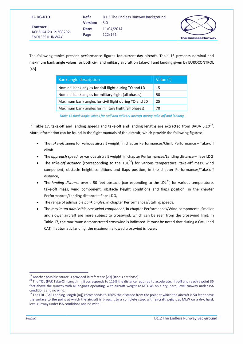
EC DG-RTD Contract: ACP2-GA-2012-308292- ENDLESS RUNWAY
Ref.: D1.2 The Endless Runway Background Version: 3.0
Date: 11/04/2014 Page 122/161
Public
D1.2 The Endless Runway Background
The following tables present performance figures for current-day aircraft. Table 16 presents nominal and
maximum bank angle values for both civil and military aircraft on take-off and landing given by EUROCONTROL
[48].
Bank angle description Value (°)
Nominal bank angles for civil flight during TO and LD 15
Nominal bank angles for military flight (all phases) 50
Maximum bank angles for civil flight during TO and LD 25
Maximum bank angles for military flight (all phases) 70
Table 16 Bank angle values for civil and military aircraft during take-off and landing
In Table 17, take-off and landing speeds and take-off and landing lengths are extracted from BADA 3.1023.
More information can be found in the flight manuals of the aircraft, which provide the following figures:
• The take-off speed for various aircraft weight, in chapter Performances/Climb Performance – Take-off
climb
• The approach speed for various aircraft weight, in chapter Performances/Landing distance – flaps LDG
• The take-off distance (corresponding to the TOL24) for various temperature, take-off mass, wind
component, obstacle height conditions and flaps position, in the chapter Performances/Take-off
distance,
• The landing distance over a 50 feet obstacle (corresponding to the LDL25) for various temperature,
take-off mass, wind component, obstacle height conditions and flaps position, in the chapter
Performances/Landing distance – flaps LDG,
• The range of admissible bank angles, in chapter Performances/Stalling speeds,
• The maximum admissible crosswind component, in chapter Performances/Wind components. Smaller
and slower aircraft are more subject to crosswind, which can be seen from the crosswind limit. In
Table 17, the maximum demonstrated crosswind is indicated. It must be noted that during a Cat II and
CAT III automatic landing, the maximum allowed crosswind is lower.
23 Another possible source is provided in reference [29] (Jane’s database). 24 The TOL (FAR Take-Off Length [m]) corresponds to 115% the distance required to accelerate, lift-off and reach a point 35 feet above the runway with all engines operating, with aircraft weight at MTOW, on a dry, hard, level runway under ISA conditions and no wind. 25 The LDL (FAR Landing Length [m]) corresponds to 166% the distance from the point at which the aircraft is 50 feet above the surface to the point at which the aircraft is brought to a complete stop, with aircraft weight at MLW on a dry, hard, level runway under ISA conditions and no wind.

EC DG-RTD Contract: ACP2-GA-2012-308292- ENDLESS RUNWAY
Ref.: D1.2 The Endless Runway Background Version: 3.0
Date: 11/04/2014 Page 123/161
Public
D1.2 The Endless Runway Background
Aircraft type Aircraft description ICAO code
Engine type
Take
-off
spee
d (k
t)
Land
ing
spee
d (k
t)
Take
-off
dist
ance
(m)
Land
ing
dist
ance
(m)
Max
ban
k an
gle
(°)26
Max
cro
ssw
ind
(kt)
Large Boeing B737-300/CFM56-3B-1 Engines27
B733 Jet 157 143 2,160 1,500 30° 31-35
Medium-sized Airbus A320-232 / V2527-A5 Engines27
A322 Jet 151 137 2,190 1,440 30° 2928-3829
Regional Saab SF340B/CT7-9B Engines27
SF34 Turbo- prop
128 105 1,271 1,049 30° 35
Business jet Dassault FALCON 20/CF700-2D-227
FA20 Jet 138 129 1,450 985 30° 23
Military Fighter Rockwell B-1 Lancer (Bomber) 27
B1 Jet 250 220 2,270 1,660 60° DNF30
General aviation (leisure aircraft)
Diamond DA 4031 DA40 Jet 54-67 58-73 170 638 60° 20
Table 17 Today's aircraft TO and LDL performances and crosswind limitations
In civil engineering, for roads construction, the stopping distance in a tight turn is increased since braking is
less energetic (ref [47]). When the turn radius is lower than 5 times the speed of the vehicle, expressed in
km/hour, the stopping distance is increased by 25%. We can assume this will apply to aircraft decelerating on a
circular runway as well.
Figure 92 Geometrical constraints on a banked runway
Another aspect to look at when investigating the sectional shape of the track is the wingspan and the height of
the wingtips of the aircraft when on the curved banked track. Indeed, wing tips should never touch the runway
during the aircraft roll, take-off, and landing. A certain clearance should be adopted (e.g. 1.8 meter clearance
26 As given by the flight manuals in chapter Performances/Stalling speeds. 27 Data source: BADA 3.1. 28 Crosswind during take-off. 29 Crosswind with gusts. 30 Data Not Found 31 Data source: Airplane flight manual DA 40

EC DG-RTD Contract: ACP2-GA-2012-308292- ENDLESS RUNWAY
Ref.: D1.2 The Endless Runway Background Version: 3.0
Date: 11/04/2014 Page 124/161
Public
D1.2 The Endless Runway Background
between wingtips and ground). Reciprocally, this requirement should also be considered when designing new
aircraft adapted to the circular runway. Wingspan and wingtips height over horizontal ground are given for the
aircraft previously notified:
Aircraft type Aircraft description ICAO code Wingtips height (m) Wingspan (m)
Large Boeing B737-300/ CFM56-3B-1 Engines
B733 3 29
Medium-sized Airbus A320-232/ V2527-A5 Engine
A322 3.7 34
Regional Saab SF340B/ CT7-9B Engines
SF34 2.5 21.4
Business jet Dassault FALCON 20/ CF700-2D-2
FA20 1.5 20
Military Fighter Rockwell B-1 Lancer (Bomber)
B1 3.6 Extended: 41.8 m Swept: 24.1 m
General aviation (leisure aircraft)
Diamond DA 40 DA40 0.73 11.9
Table 18 Today's aircraft geometrical characteristics
Finally, aircraft turning radius should be considered. Aircraft turn by using their nose landing gear. Only newer
large aircraft have the capability of swivelling the main gear when making sharp turns, which reduces the
turning radius. This information will play a large role in the design of the connection between the circular
runway and the taxiways, and between the taxiways themselves.
Figure 93 Aircraft wheel track and wheelbase
wheel track
wheelbase
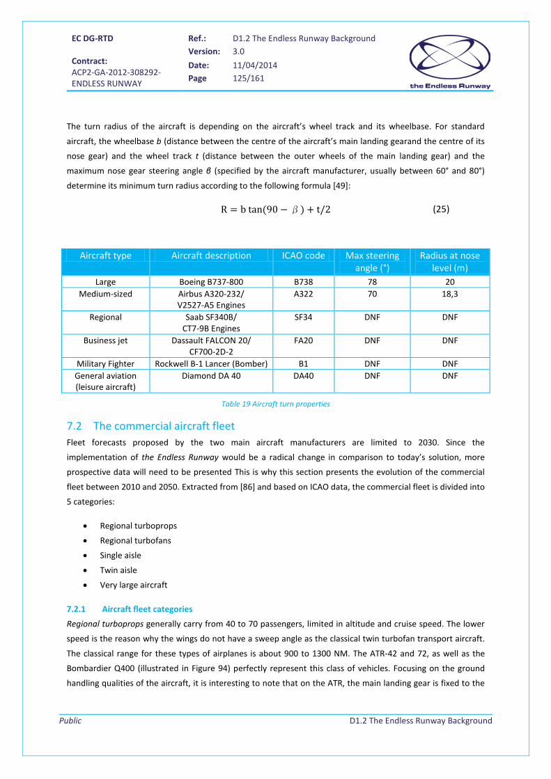
EC DG-RTD Contract: ACP2-GA-2012-308292- ENDLESS RUNWAY
Ref.: D1.2 The Endless Runway Background Version: 3.0
Date: 11/04/2014 Page 125/161
Public
D1.2 The Endless Runway Background
The turn radius of the aircraft is depending on the aircraft’s wheel track and its wheelbase. For standard
aircraft, the wheelbase b (distance between the centre of the aircraft’s main landing gearand the centre of its
nose gear) and the wheel track t (distance between the outer wheels of the main landing gear) and the
maximum nose gear steering angle β (specified by the aircraft manufacturer, usually between 60° and 80°)
determine its minimum turn radius according to the following formula [49]:
R = b tan (90 −β) + t/2 (25)
Aircraft type Aircraft description ICAO code Max steering angle (°)
Radius at nose level (m)
Large Boeing B737-800 B738 78 20 Medium-sized Airbus A320-232/
V2527-A5 Engines A322 70 18,3
Regional Saab SF340B/ CT7-9B Engines
SF34 DNF DNF
Business jet Dassault FALCON 20/ CF700-2D-2
FA20 DNF DNF
Military Fighter Rockwell B-1 Lancer (Bomber) B1 DNF DNF General aviation (leisure aircraft)
Diamond DA 40 DA40 DNF DNF
Table 19 Aircraft turn properties
7.2 The commercial aircraft fleet Fleet forecasts proposed by the two main aircraft manufacturers are limited to 2030. Since the
implementation of the Endless Runway would be a radical change in comparison to today’s solution, more
prospective data will need to be presented This is why this section presents the evolution of the commercial
fleet between 2010 and 2050. Extracted from [86] and based on ICAO data, the commercial fleet is divided into
5 categories:
• Regional turboprops
• Regional turbofans
• Single aisle
• Twin aisle
• Very large aircraft
7.2.1 Aircraft fleet categories
Regional turboprops generally carry from 40 to 70 passengers, limited in altitude and cruise speed. The lower
speed is the reason why the wings do not have a sweep angle as the classical twin turbofan transport aircraft.
The classical range for these types of airplanes is about 900 to 1300 NM. The ATR-42 and 72, as well as the
Bombardier Q400 (illustrated in Figure 94) perfectly represent this class of vehicles. Focusing on the ground
handling qualities of the aircraft, it is interesting to note that on the ATR, the main landing gear is fixed to the
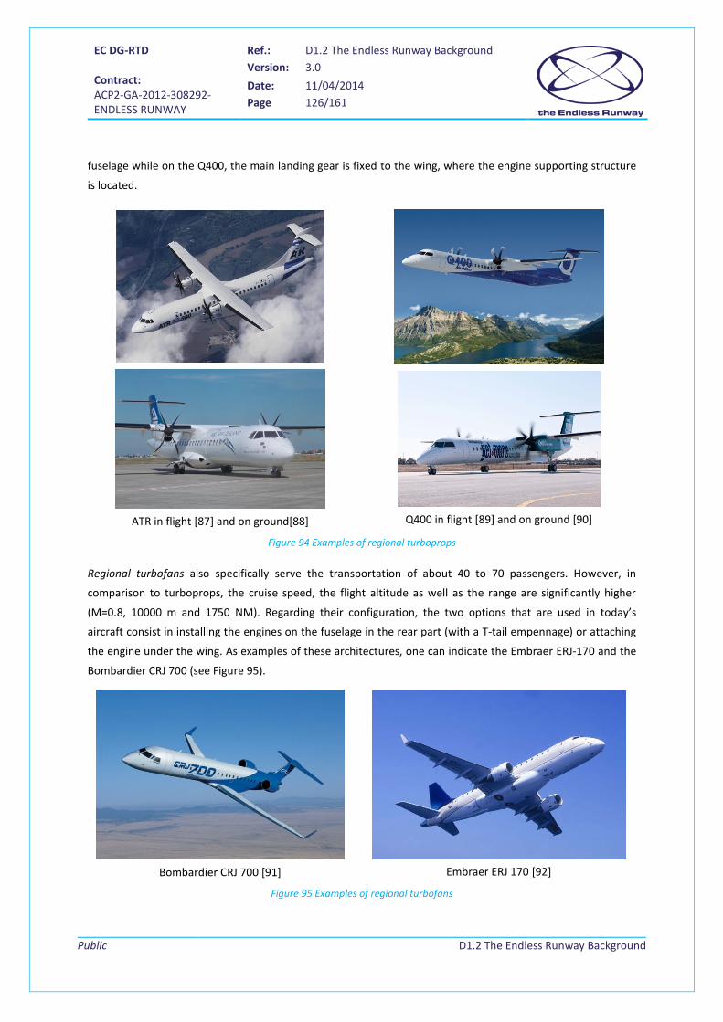
EC DG-RTD Contract: ACP2-GA-2012-308292- ENDLESS RUNWAY
Ref.: D1.2 The Endless Runway Background Version: 3.0
Date: 11/04/2014 Page 126/161
Public
D1.2 The Endless Runway Background
fuselage while on the Q400, the main landing gear is fixed to the wing, where the engine supporting structure
is located.
ATR in flight [87] and on ground[88]
Q400 in flight [89] and on ground [90]
Figure 94 Examples of regional turboprops
Regional turbofans also specifically serve the transportation of about 40 to 70 passengers. However, in
comparison to turboprops, the cruise speed, the flight altitude as well as the range are significantly higher
(M=0.8, 10000 m and 1750 NM). Regarding their configuration, the two options that are used in today’s
aircraft consist in installing the engines on the fuselage in the rear part (with a T-tail empennage) or attaching
the engine under the wing. As examples of these architectures, one can indicate the Embraer ERJ-170 and the
Bombardier CRJ 700 (see Figure 95).
Bombardier CRJ 700 [91]
Embraer ERJ 170 [92]
Figure 95 Examples of regional turbofans

EC DG-RTD Contract: ACP2-GA-2012-308292- ENDLESS RUNWAY
Ref.: D1.2 The Endless Runway Background Version: 3.0
Date: 11/04/2014 Page 127/161
Public
D1.2 The Endless Runway Background
Single aisle aircraft form an important group of aircraft in the commercial fleet. Passenger capacity ranges
from 100 to 200 and the available range enables to cover key routes at the national and international (within
Europe) level. Given its size, this category of aircraft is fundamental to the aeronautics industry economy.
Usually, a basic aircraft is produced and subsequently, derived versions are studied to accommodate the right
number of passengers (A318 and A321 are derived versions of the A320). The success of the Airbus A320 and
the Boeing B737 families led to the development of enhanced versions called A320 NEO and B737 MAX (see
illustrations in Figure 96). From an external point of view, the new airdraft can be recognized by the new
“sharklets” installed on A320 NEO and the innovative winglets on the B737 MAX (both on the wing tips).
Airbus A320 NEO [93]
Boeing B737 MAX [94]
Figure 96 Examples of Single Aisle Aircraft
For intercontinental flights, industry proposes twin aisle aircraft that have a capacity from 250 to 350
passengers. The cruise speed is around M=0.84 and the range extends 5000 NM for the basic versions. Other
versions have been produced in a second step with the objective of extending significantly the possible flight
distance. Once equipped with 4 engines, aircraft of this category are now converging to a two-engines
configuration that is compliant with the ETOPS rules (Extended-range Twin-engine Operational Performance
Standards). The latest products in this category are the Boeing B787 (already in service) and the Airbus A350
XWB set for a first flight in 2013 (see Figure 97).
Boeing B787 [94]
Airbus A350 XWB [93]
Figure 97 Examples of Twin Aisle Aircraft
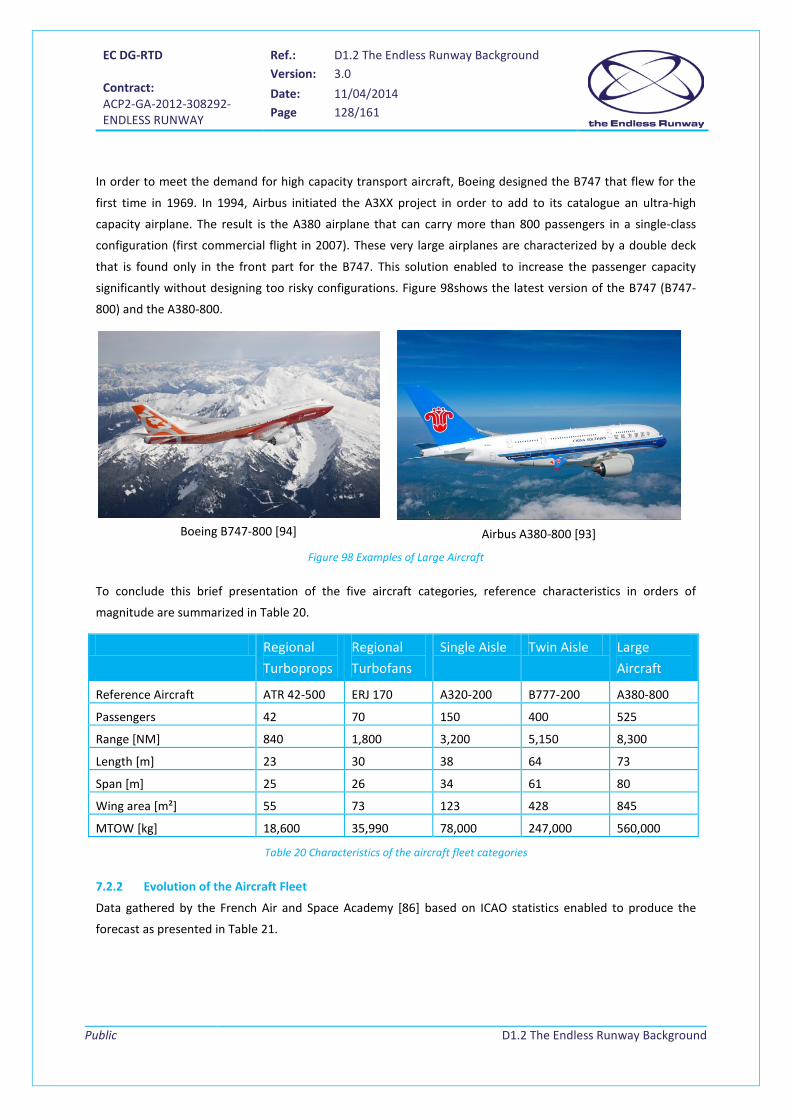
EC DG-RTD Contract: ACP2-GA-2012-308292- ENDLESS RUNWAY
Ref.: D1.2 The Endless Runway Background Version: 3.0
Date: 11/04/2014 Page 128/161
Public
D1.2 The Endless Runway Background
In order to meet the demand for high capacity transport aircraft, Boeing designed the B747 that flew for the
first time in 1969. In 1994, Airbus initiated the A3XX project in order to add to its catalogue an ultra-high
capacity airplane. The result is the A380 airplane that can carry more than 800 passengers in a single-class
configuration (first commercial flight in 2007). These very large airplanes are characterized by a double deck
that is found only in the front part for the B747. This solution enabled to increase the passenger capacity
significantly without designing too risky configurations. Figure 98shows the latest version of the B747 (B747-
800) and the A380-800.
Boeing B747-800 [94]
Airbus A380-800 [93]
Figure 98 Examples of Large Aircraft
To conclude this brief presentation of the five aircraft categories, reference characteristics in orders of
magnitude are summarized in Table 20.
Regional Turboprops
Regional Turbofans
Single Aisle Twin Aisle Large Aircraft
Reference Aircraft ATR 42-500 ERJ 170 A320-200 B777-200 A380-800
Passengers 42 70 150 400 525
Range [NM] 840 1,800 3,200 5,150 8,300
Length [m] 23 30 38 64 73
Span [m] 25 26 34 61 80
Wing area [m²] 55 73 123 428 845
MTOW [kg] 18,600 35,990 78,000 247,000 560,000
Table 20 Characteristics of the aircraft fleet categories
7.2.2 Evolution of the Aircraft Fleet
Data gathered by the French Air and Space Academy [86] based on ICAO statistics enabled to produce the
forecast as presented in Table 21.
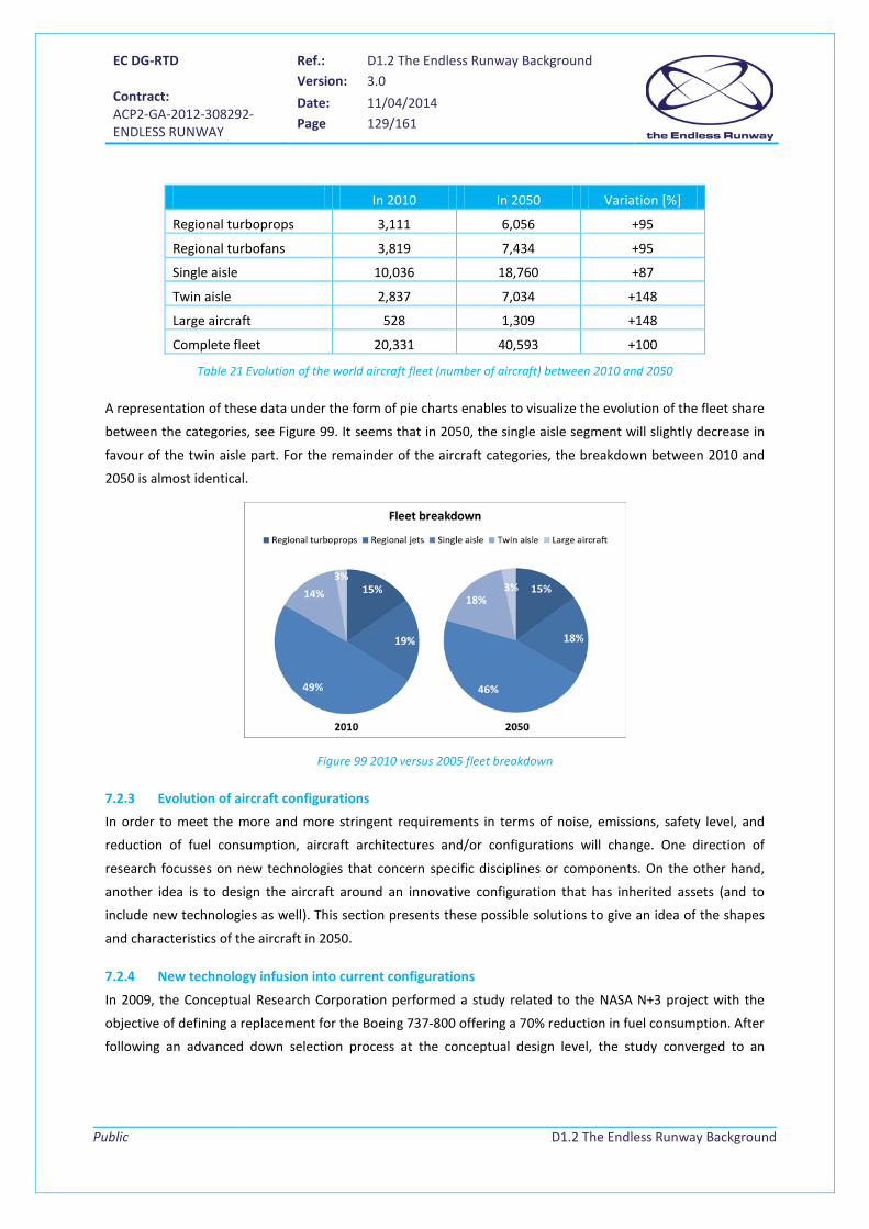
EC DG-RTD Contract: ACP2-GA-2012-308292- ENDLESS RUNWAY
Ref.: D1.2 The Endless Runway Background Version: 3.0
Date: 11/04/2014 Page 129/161
Public
D1.2 The Endless Runway Background
In 2010 In 2050 Variation [%]
Regional turboprops 3,111 6,056 +95
Regional turbofans 3,819 7,434 +95
Single aisle 10,036 18,760 +87
Twin aisle 2,837 7,034 +148
Large aircraft 528 1,309 +148
Complete fleet 20,331 40,593 +100
Table 21 Evolution of the world aircraft fleet (number of aircraft) between 2010 and 2050
A representation of these data under the form of pie charts enables to visualize the evolution of the fleet share
between the categories, see Figure 99. It seems that in 2050, the single aisle segment will slightly decrease in
favour of the twin aisle part. For the remainder of the aircraft categories, the breakdown between 2010 and
2050 is almost identical.
Figure 99 2010 versus 2005 fleet breakdown
7.2.3 Evolution of aircraft configurations
In order to meet the more and more stringent requirements in terms of noise, emissions, safety level, and
reduction of fuel consumption, aircraft architectures and/or configurations will change. One direction of
research focusses on new technologies that concern specific disciplines or components. On the other hand,
another idea is to design the aircraft around an innovative configuration that has inherited assets (and to
include new technologies as well). This section presents these possible solutions to give an idea of the shapes
and characteristics of the aircraft in 2050.
7.2.4 New technology infusion into current configurations
In 2009, the Conceptual Research Corporation performed a study related to the NASA N+3 project with the
objective of defining a replacement for the Boeing 737-800 offering a 70% reduction in fuel consumption. After
following an advanced down selection process at the conceptual design level, the study converged to an

EC DG-RTD Contract: ACP2-GA-2012-308292- ENDLESS RUNWAY
Ref.: D1.2 The Endless Runway Background Version: 3.0
Date: 11/04/2014 Page 130/161
Public
D1.2 The Endless Runway Background
evolved configuration based on specific technologies [95] of open rotors for the propulsion system, active
aeroelastic wings, advanced composites, and flight controls.
The integration of these technologies results in the design of an Open Rotor Tailless Aircraft (ORTA) with
retractable canards and chin rudder capable of transporting 180 passengers over 2800 NM (at a speed of
M=0.7). Regarding the fuel burn, the new design provides a 60% reduction. In Figure 100, it is possible to
observe the high aspect ratio wing (15 vs. 9.45 for the B737-800) that clearly favours the fuel consumption.
Figure 100 Possible single aisle aircraft in 2050 (ORTA) [94]
Within the same NASA Project, Boeing performed its own research called SUGAR (Subsonic Ultra Green
Aircraft Research) regarding single aisle aircraft to enter into service in 2035. In this paragraph, it is decided to
present the SUGAR Volt, a possible future aircraft using a hybrid engine (batteries + fuel). As for the vehicle
defined by the Conceptual Research Corporation, the SUGAR Volt airplane aims to fly at a speed of M=0.7 and
it relies on an important number of new technologies [96]. The following figure illustrates this new aircraft
concept that reaches also a reduction of 60% in fuel consumption (for a 900 NM mission):
Necessary Technology developments
Hybrid Engine Technology
Engine / airframe acoustics
Advanced Engine Technology
Alternative Fuels
Aerodynamics
Advanced subsystems
Structural concepts
Structural materials
High Span Strut Braced Wing
Figure 101 Possible single aisle aircraft with hybrid engines in 2050 (SUGAR Volt) [94]

EC DG-RTD Contract: ACP2-GA-2012-308292- ENDLESS RUNWAY
Ref.: D1.2 The Endless Runway Background Version: 3.0
Date: 11/04/2014 Page 131/161
Public
D1.2 The Endless Runway Background
The European counterparts of the programs described in this section, like the CleanSky program, have been
mentioned before in this document.
7.2.5 Innovative configurations
For aircraft designers, another option to improve the performances of an airplane is the exploration of radical
configurations that have important potential benefits. A well-known innovative architecture is the Blended
Wing Body (BWB) or Hybrid Wing Body (HWB). It is an evolution of the “Flying wing” concept to better
accommodate the payload without sacrificing the aerodynamic efficiency [65]. This aerodynamic efficiency is
indeed the key advantage of the BWB: the lift over drag ratio can go up to 27 (today’s aircraft have efficiency
about 18).
In [96], Boeing designs a BWB based on the requirements of a single aisle typical configuration. The resulting
aircraft, called SUGAR Ray, providing a gain of 43% in the fuel consumption (for a 900 NM mission) compared
to current-day aircraft configurations, is illustrated in Figure 102(data correspond to the turbofan version).
Figure 102 The SUGAR Ray concept
For comparison of these advanced concepts with today’s aircraft, Table 22 specifies the aircraft characteristics.
2010 2010 2050 2050 2050 Reference Aircraft A320-200 B737-800 ORTA SUGAR Volt SUGAR Ray
Passengers 150 180 180 154 154
Design Range [NM] 3,200 2,800 2,800 3,500 3,500
Length [m] 38 40 38 40 24
Span [m] 34 36 35 61 55
Wing area [m²] 123 125 82 139 385
MTOW [kg] 78,000 79,000 79,000 70,260 78,290
Table 22 Aircraft characteristics (2010 vs. 2050)

EC DG-RTD Contract: ACP2-GA-2012-308292- ENDLESS RUNWAY
Ref.: D1.2 The Endless Runway Background Version: 3.0
Date: 11/04/2014 Page 132/161
Public
D1.2 The Endless Runway Background
This chart clearly indicates that the trend for future aircraft is to increase the wing span. In this manner, the
aspect ratio is higher and the overall aerodynamic efficiency is better. However, it is obvious that ground
operations would more complex (future concepts proposed by Boeing include indeed a folding system to
reduce the area covered by the airplane on the ground). Although exact characteristics of these aircraft are not
yet known, this particular change in the geometry of the future aircraft might be a limiting parameter in the
definition of the Endless Runway concept with banked tracks.
7.3 New scenarios In addition to the classical missions that are covered by the five aircraft categories identified earlier in the
paragraph, recent studies [97] [98] present innovative missions that correspond to a new type of aircraft. In
the Endless Runway, it is interesting to consider these new missions early in the project to really widen the
concept exploration.
7.3.1 Personal Air Transport
Several initiatives exist for the development of personal air vehicles, ranging from aircraft that will need to be
flown by pilots until fully autonomous flying personal tansport means. One of the most futuristic concepts is
developed in the PPLANE (Personal Plane) project. In the PPLANE project [97], the objective is to investigate
the possibility to perform a fully automated mission between small airports with aircraft that would be able to
transport 4 to 6 passengers on board (operated by a remote ground pilot) over a distance of 300 NM at a
speed of M=0.4. The PPlane project is a direct follow up study to Out-of-the-Box project that aimed to identify
potential new concepts and technologies for future personal air transport. This new type of mission is
expected to increase personal mobility, reduce issues related to traffic congestion, and offer access to isolated
areas that cannot be reached through ground transports. A PPLANE can also be part of an intermodal
transport network. Figure 103 illustrates the typical mission of a Personal Air Vehicle with the different links
between the aircraft and the ground to achieve the automated flight.
Figure 103 PPLANE mission profile
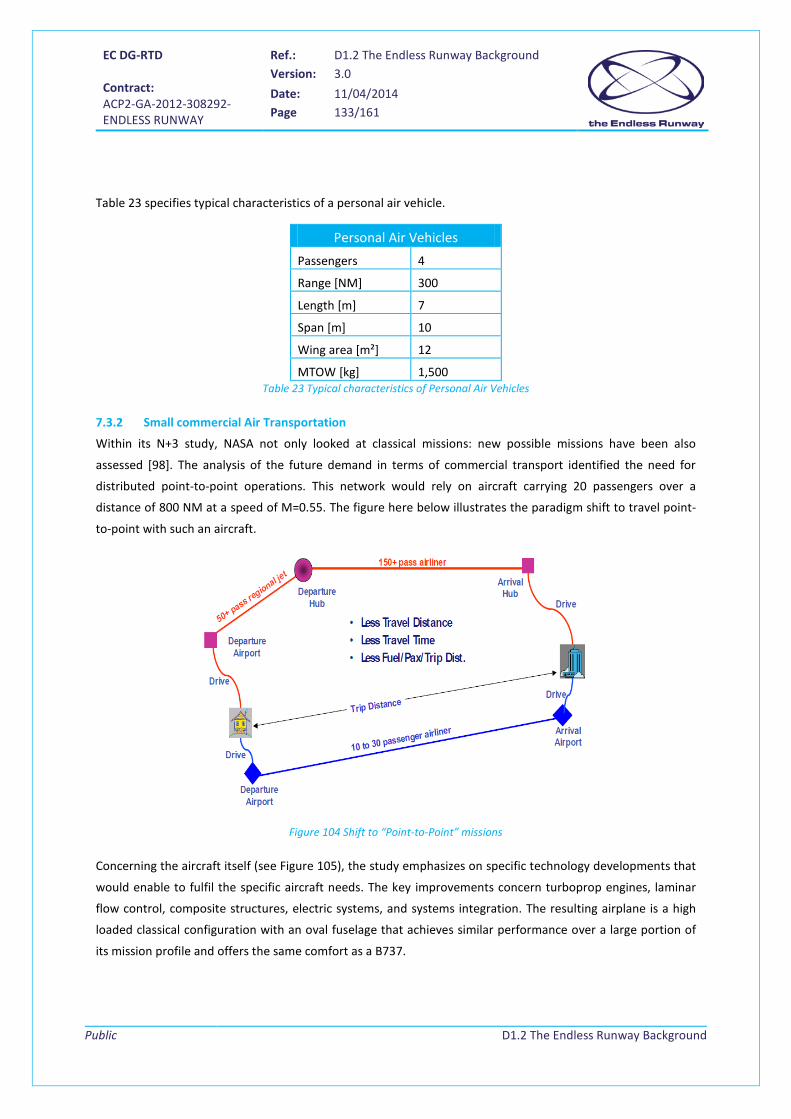
EC DG-RTD Contract: ACP2-GA-2012-308292- ENDLESS RUNWAY
Ref.: D1.2 The Endless Runway Background Version: 3.0
Date: 11/04/2014 Page 133/161
Public
D1.2 The Endless Runway Background
Table 23 specifies typical characteristics of a personal air vehicle.
Table 23 Typical characteristics of Personal Air Vehicles
7.3.2 Small commercial Air Transportation
Within its N+3 study, NASA not only looked at classical missions: new possible missions have been also
assessed [98]. The analysis of the future demand in terms of commercial transport identified the need for
distributed point-to-point operations. This network would rely on aircraft carrying 20 passengers over a
distance of 800 NM at a speed of M=0.55. The figure here below illustrates the paradigm shift to travel point-
to-point with such an aircraft.
Figure 104 Shift to “Point-to-Point” missions
Concerning the aircraft itself (see Figure 105), the study emphasizes on specific technology developments that
would enable to fulfil the specific aircraft needs. The key improvements concern turboprop engines, laminar
flow control, composite structures, electric systems, and systems integration. The resulting airplane is a high
loaded classical configuration with an oval fuselage that achieves similar performance over a large portion of
its mission profile and offers the same comfort as a B737.
Personal Air Vehicles Passengers 4
Range [NM] 300
Length [m] 7
Span [m] 10
Wing area [m²] 12
MTOW [kg] 1,500

EC DG-RTD Contract: ACP2-GA-2012-308292- ENDLESS RUNWAY
Ref.: D1.2 The Endless Runway Background Version: 3.0
Date: 11/04/2014 Page 134/161
Public
D1.2 The Endless Runway Background
2050
Reference Aircraft GE SCTA
Passengers 20
Range [NM] 800
Length [m] 14.7
Span [m] 16.2
Wing area [m²] 18.9
MTOW [kg] 6651
Figure 105 Characteristics of a 2050 Small Commercial Transport Aircraft (SCTA) [98]

EC DG-RTD Contract: ACP2-GA-2012-308292- ENDLESS RUNWAY
Ref.: D1.2 The Endless Runway Background Version: 3.0
Date: 11/04/2014 Page 135/161
Public
D1.2 The Endless Runway Background
8 Conclusion This document has provided an overview of aspects related to a possible circular runway. The document has
described earlier work (theoretical and practical), and aspects related to the construction of runways and the
airport infrastructure, ATM procedures, and aircraft design. Emerging and innovative airport concepts and
future air transport have been described in order to set up a framework for the Endless Runway.
The circular runway is not a completely new idea. The first reference to a circular runway track was found in a
publication from 1919, where a sky-based runway would support commuters travelling to their office buildings
in New York. The first trials with a circular take-off were performed as stunts in 1938. The idea of using a
circular runway became popular in patent claims in the sixties, when several concepts, constructions, and add-
ons were filed as patents. The US Navy performed operational trials with landing on a circular track, from
which extensive reports can be found. The idea was abandoned at that time, as aircraft and ATM procedures
were not available for installation and implementation of circular runways in a large scale. However, the idea
of the Endless Runway appears every now and then in ATM literature and airport design studies as an
interesting solution to solving the cross- and tailwind issues during landing and take-off, where just as well,
airport operations can be performed more efficiently with a circular runway track around an optimised airport
terminal building construction.
The three major aspects of the Endless Runway are:
• The construction of the runway and design of terminal buildings inside the ring.
• The application of existing or the development of new ATM procedures.
• Aircraft design aspects.
8.1 Runway construction and airport design The construction of the runway surface for the Endless Runway will focus on the necessary dimensions of the
runway, i.e. the diameter of the circle, the width of the runway, and the needed bank angle (if any). Current
regulations for runway identification and marking will have to be modified for the Endless Runway. Especially,
performing a landing using visual and navigation aids will be different from current day practice.
The majority of the airport infrastructure will be constructed inside the circular runway track, thus setting
requirements to the size of the circle. It will need to cover all facilities necessary for aircraft taxiing, parking,
and servicing. The terminal buildings will need to be constructed to allow passengers, luggage, and cargo
handling in the same ways as it takes place at airports nowadays. Special attention will need to be paid to the
access to the airport, as passengers, crew, and service handlers will always have to cross the runway circle at
some point. A trend is observed towards multi-modal airport access through the use of train and automated
people mover systems. Emergency situations in which aircraft and passengers might need to get easily outside
the circle should be considered as well.
EC DG-RTD Contract: ACP2-GA-2012-308292- ENDLESS RUNWAY
Ref.: D1.2 The Endless Runway Background Version: 3.0
Date: 11/04/2014 Page 136/161
Public
D1.2 The Endless Runway Background
One major aspect for further research is the consideration of the environmental and the societal impact of the
Endless Runway. Aircraft noise, CO2 and NOx emissions, and third party risk will not be concentrated along
existing runway arrival and departure routes, but will be spread over the whole terminal manoeuvring area
around the airport. This diffusion may have a positive impact over currently overflown populations, but it may
be regarded negative as well as more people will experience nuisance. Procedures may need to be established
to avoid overflying heavily populated areas.
8.2 ATM procedures The first things that will require attention are descent and climb manoeuvres. Routes for flying in and out the
airport will not be fixed any longer. Aircraft will fly in from and out to any direction as the runway threshold is
not a fixed position. Landing systems will need further exploration as aircraft will not necessary approach the
Endless Runway in a straight line; MLS and GPS systems are better suited for operation.
A concept for landing at different positions on one runway is already in use at airports where they operate the
displaced threshold procedure. This procedure allows aircraft to land at different positions on one runway,
avoiding wake turbulence, hence enabling shorter separation and providing more capacity. This procedure is
interesting for further research as the idea of operating multiple thresholds at one runway can be used in the
operational concept of the Endless Runway.
The current development in ATM, implemented in the SESAR program, is the application of 4D trajectories.
Aircraft will fly assigned routes in space and time and negotiate these routes in advance. Together with
planning systems for arrival and departure management, and good ground operations planning, this will allow
efficient operations on the circular runway. Aircraft will be able to automatically determine their optimised
flight profile, using continuous descent approaches and continuous climb operations. Good planning is also
necessary for the pilots’ and air traffic controllers’ situational awareness, who will both need a good overview
of the traffic situation in a newly developed HMI.
8.3 Aircraft Neither aircraft configurations nor the aircraft fleet composition are expected to change significantly over the
next decades. Although several new aircraft types are proposed (BWB and personal air vehicles) from which
the characteristics are not yet fully known, it will suffice to use existing aircraft parameters for the evaluation
of accessibility of aircraft to the Endless Runway. Important aspects concerning the aircraft configuration are
the wing tip and engine clearance from the bank angle of the runway. This must still apply in case of incidents,
like flat tires. Aircraft turn radius and allowed bank angle must allow them to operate the Endless Runway.
For the comfort of passengers, the centrifugal forces must not exceed values that will cause them to feel
uncomfortable.
Trials from the sixties have demonstrated that the circular runway track is forgiving in such that it tends to
correct pilot errors when landing too high with a slow speed or too low with a high speed on the banked track.
The aircraft will “sweep” to the right position in the track. Just as well, if the aircraft reaches the track with

EC DG-RTD Contract: ACP2-GA-2012-308292- ENDLESS RUNWAY
Ref.: D1.2 The Endless Runway Background Version: 3.0
Date: 11/04/2014 Page 137/161
Public
D1.2 The Endless Runway Background
only the outer landing gear wheel first, the aircraft will be able to maintain position and finish the landing
without problems.
8.4 Overall conclusions In the research to the state of the art on circular runways and associated airport and aircraft design and
considering ATM procedures, no real show stoppers have been found for the Endless Runway project.
Obviously, many questions will need to be answered in the course of the project. Which circle size will allow
sufficient building activity inside the circle? How will passengers and airport personnel get access to the
infrastructure inside the circle? What is the best bank angle? How should aircraft approach the runway? How
to indicate the runway threshold (touchdown point) to the pilot? How to avoid overflying densely crowded
areas? What equipment will be necessary? Etc.
The results of the literature survey in this document are promising and suggest that a circular runway can be
developed with current and expected technology. Today’s aircraft characteristics allow to take off and land
with speeds and low altitude bank angles compatible with the operation on a circular track. The Endless
Runway fits in future concepts that specify improved planning of operations, new navigation equipment, and
intermodal transport.
One or more operational concepts will need to be developed and further evaluated to define exact ways of
working with the Endless Runway.
EC DG-RTD Contract: ACP2-GA-2012-308292- ENDLESS RUNWAY
Ref.: D1.2 The Endless Runway Background Version: 3.0
Date: 11/04/2014 Page 138/161
Public
D1.2 The Endless Runway Background
9 References [1] Description of Work – The Endless Runway, version 1.1, June 20th, 2012 [2] Roosts for City Airplane : Would This Circular Track Solve the Landing Problem?, in Popular Science,
June 1919 [3] Circular Take-off, in Time Magazine, March 1955 [4] Jet-age Runway Problem Solved?, FLIGHT, Dec 1957 [5] Navy Tests Design for Airport With Circular, Banked Runway, The Milwaukee Journal, Dec 1965 [6] Circular Runway concept, The age, Dec 1965 [7] New Directions, in Time Magazine, December 1965 [8] U.S. Navy Ends Tests on Revolutionary New Airport Concept, The telegraph, Dec 1965 [9] Coming: Airports Shaped Like Wheels?, Popular Science, June 1966 [10] Circular runways for airport?, NewScientist Magazine issue 2578, Nov. 2006 [11] US Patent 3157374, Airport Design, James S. Conrey, Nov 1964 [12] US Patent 3173634, Closed Track Airport, A. Woldemar, March 1965 [13] US Patent 3325124, Closed Track Airport with Inlet Runway for Straight Instrument Landings, A.
Woldemar, June 1967 [14] US Patent 3333796, Closed Track Airport with Straight Runways for Instrument Landing and Take-off, A.
Woldemar, August 1967 [15] Translation curves for highways, United States. Bureau of Public Roads, Joseph Barnett, U.S. Govt. Print
Off., 1938 [16] Concrete pavement manual, Portland Cement Association, 1955 [17] US Patent 3701501, Two Circular Runways, Robert G. Scelze, Oct 1972 [18] “The circular Runway” report, U.S. Navy, Apr 1965 [19] Landings on a Round Runway!, Naval Aviation News, March 1965 [20] Circular Airport Runways and Other Neat Solutions for "Airport of the Future" Design Comp, Core 77
Design Magazine and resource, 22 Feb 2012 [21] Circular Runway at ONZ, How Does It Work?, airliners.net forum, Sept 2006 [22] UK aerial targets, Chris Davis, July 24, 2008 [23] US Patent 1388319, Peter James Backus, Landing Station for Aircraft, Filing date Dec. 27, 1920, Issue
date Aug. 23, 1921 [24] College Physics, Raymond A. Serway, Jerry S. Faughn,Chris Vuille, Cengage Learning, Jan 2011 [25] Course in Physics for IIT-JEE, Tata McGraw, Hill Education, 2011 [26] ICAO Annex 14, Volume I, Aerodrome design and operations [27] ICAO Annex 16, Environmental Protection, Volume I, Aircraft Noise [28] ICAO 9157 – Aerodrome Design Manual [29] Jane’s database (http://jawa.janes.com/public/jawa/index.shtml) [30] US Patent 1854336, Clarence W. King, Floating Landing Stage, Filing date Feb. 10. 1931, Issue date Apr.
19, 1932 [31] US Patent 2430178, Selby H. Kurfiss et. Al., Floating Airplane Field, Filing date Mar 9, 1946, Issue date
Nov. 4 1947 [32] US Patent 5398635, Durando, A.R. and H.M. Weiss, Floating Airport, Filing date Nov. 18, 1993, Issue
date Mar. 21, 1995

EC DG-RTD Contract: ACP2-GA-2012-308292- ENDLESS RUNWAY
Ref.: D1.2 The Endless Runway Background Version: 3.0
Date: 11/04/2014 Page 139/161
Public
D1.2 The Endless Runway Background
[33] US Patent 5588387, Wentworth J. Tellington, Floating Platform, Filing date Mar. 14, 1995, Issue date Dec. 31, 1996
[34] US Patent 5906171, Per Herbert Kristensen et.al, Floating Runway, Filing date Sept. 24, 1997, Issue date May 25, 1999
[35] US Patent 6651578, Patrick H. Gorman, Floating Structures, Filing Date Mar. 27, 2002, Issue date Nov. 25, 2003
[36] Foundations for the development of the airport Schiphol – report issued by the commission for studying the extension of the airport Schiphol, chairman: U.F.M. Dellaert.
[37] US Patent 2342773, Samual K. Wellman, Landing Platform for Airplanes, March 28, 1942 [38] US Patent 2399611, E.R. Armstrong et. Al, Submersible Seadrome, Filing date May 14, 1942, Issue date
May 7, 1946. [39] US Patent 6341573, Jon Buck, Ship to Platform Transformer, Filing date Mar 9, 2001, Issue date Jan. 29,
2002. [40] US Patent 5368257, Harry E. Novinger,Variable One Way Airport, Filing date Jan. 13, 1993, Issue date
Nov. 29, 1994 [41] “Thinking ahead”, FENTRESS ARCHITECTS, Airport World, April-May 2012 [42] http://wikimapia.org/9385276/ONZ-Runway-Circle-Remants [43] Pilot’s handbook of aeronautical knowledge (chapters 4, 5, 13 and 16), FAA, FAA-H-8083-25ª, 2008 [44] Advisory_Circular 150/5300-13 Airport Design, FAA, 30/12/2011 [45] Instruction technique sur les aérodromes civils, DGAC-STAC (Service Technique de l’Aviation Civile),
01/03/2002 [46] US Patent 1,388,319, P.J. Backus, Landing Station for aircraft, Filing date Dec. 27 1920, Issue date Auf
23, 1921 [47] Comprendre les principaux paramètres de conception géométrique des routes, Service d’Etudes
Techniques des Routes et Autoroutes, issue date January 2006 [48] User Manual for the Base of aircraft Data (BADA), revision 3.10, EEC Technical/Scientific Report No.
12/04/10-45, April 2012 [49] Planning and design of airports, Robert Horonjeff, fifth edition [50] Ashford, N., H. Stanton, and C. More, Airport Operations, McGraw-Hill Education publications, ISBN
7980070030770, 1997 [51] Airport Systems: Planning, Design, and Management, Richard de Neufville, Amedeo Odoni, 2002 [52] Apuntes Edificación y Equipos Aeroportuarios, A. París Loreiro (Publicaciones ETSIA UPM) [53] http://en.wikipedia.org/wiki/Intermodal_passenger_transport [54] La Actividad Aeroportuaria y el Medio Ambiente; Sebastián Delgado Moya, Marcos García Cruzado,
Mario García Galludo, José Mª Guillamón Viamonte, Manuel Recuerdo López, Carlos San Martín Castaño
[55] http://ionelberdin.com/2011/05/visita-a-la-t4-del-aeropuerto-de-madrid-barajas/ [56] Wind director indicator: http://www.pasionporvolar.com/blog/ayudas-visuales-en-los-aeropuertos-
senalizaciones [57] Landing direction indicator: http://www.pasionporvolar.com/blog/ayudas-visuales-en-los-aeropuertos-
senalizaciones [58] Runway number signal: http://www.pasionporvolar.com/blog/ayudas-visuales-en-los-aeropuertos-
senalizaciones [59] Airport signs: http://www.topskills.com/fsbooks_pim.htm
EC DG-RTD Contract: ACP2-GA-2012-308292- ENDLESS RUNWAY
Ref.: D1.2 The Endless Runway Background Version: 3.0
Date: 11/04/2014 Page 140/161
Public
D1.2 The Endless Runway Background
[60] Runway beacons: http://www.grupocecom.es/es/el_grupo/en_portada/12-cecom_suministra_el_material_de_ayudas_visuales_en_el_aeropuerto_de_castellon
[61] Runway beacon (Barcelona): http://www.l4ado.com/masinfo_foto.asp?idfoto=371 [62] Airport lights: http://iknowifeel.blogspot.com.es/2012/05/airport-lights.html
[63] Amsterdam Airport Schiphol, Create a Barrier of Silence, results of the design contest, www.schiphol.nl/ontwerpwedstrijd
[64] EREA vision for the future – Towards the future generation of Air Transport System, Publisher: Association of European Research Establishments in Aeronautics, P.O.Box 90502, 1059 CM Amsterdam, October 2010
[65] EREA ATS 2050 Phase 2, From Air Transport system 2050 Vision to Planning for Research and Innovation, published by the Association of European Research Establishments in Aeronautics, May 2012.
[66] Flightpath 2050, Europe’s Vision for Aviation Report of the High Level Group on Aviation Research, EUROPEAN COMMISSION, Directorate-General for Research and Innovation, Directorate General for Mobility and Transport, Luxembourg: Publications Office of the European Union, 2011, ISBN 978-92-79-19724-6, doi 10.2777/50266, © European Union, 2011
[67] ACARE (Advisory Council for Aeronautics Research in Europe), Aeronautics and Air Transport: Beyond Vision 2020 (Towards 2050), Background Document, Issued: June 2010
[68] Airport2050, Vision 2050, Deliverable D2-1-1, November 2011 [69] Parasuraman R., T.B. Sheridan, and C.D. Wickens, A model for types and levels of human interaction
with automation, IEEE Transactions on Systems, Man & Cybernetics, 2000, vol.30, pp.286-297. ISSN 0018-9472.
[70] Leeuwen, P. van, A Vision on the Air Transport System of 2050, version 1.0, Amsterdam, January 2012, NLR-TR-2012-202
[71] ACARE, Strategic Research Agenda, volume 1, 2004 [72] ACARE, Strategic Research Agenda, volume 2, 2004 [73] ACARE, Aeronautics and Air Transport: Beyond Vision 2020 (Towards 2050), Background Document,
Issued: June 2010 [74] Berghof, R. et.al., CONSAVE 2050 Final Technical Report, July 2005, G4MA-CT-2002-04013 [75] ACARE, Meeting Societies Needs and Winning Global Leadership, January 2001 [76] SESAR D3 [77] RTCA, Report of the Radio Technical Commission for Aeronautics (RTCA) Board ofDirectors' Select
Committee on Free Flight, 1995 [78] J.M. Hoekstra et all, Free Flight in a Crowded Airspace?, 3rd USA/Europe Air Traffic Management R&D
Seminar Napoli, June 2000 [79] Airspace for Tomorrow, “Developing the United Kingdom’s airspace arrangements in a safe, sustainable
and efficient way “, CAA (UK), 2009 [80] Airspace for Tomorrow-2, “Modernising the United Kingdom’s airspace arrangements in a safe,
sustainable and efficient way”, CAA, 2009 [81] Airspace for Tomorrow-3, “Modernising the United Kingdom’s airspace arrangement in a safe,
sustainable and efficient way”, CAA, 2009 [82] European Commission, Out Of The Box Ideas about the future of air transport Part 2, 2007

EC DG-RTD Contract: ACP2-GA-2012-308292- ENDLESS RUNWAY
Ref.: D1.2 The Endless Runway Background Version: 3.0
Date: 11/04/2014 Page 141/161
Public
D1.2 The Endless Runway Background
[83] THE 2015 AIRSPACE CONCEPT & STRATEGY FOR THE ECAC AREA& KEY ENABLERS, Eurocontrol, 28.02.2008, Edition 2.0
[84] “Global Market Forecast” by Airbus [85] “Global Market Outlook” by Boeing [86] “Comment volerons-nous en 2050”, Air and Space Academy, 2011 [87] Website: http://www.atraircraft.com/ [88] Website: http://www.aviationadvertiser.com.au/ [89] Website: http://q400nextgen.com/ [90] Website: http://flyingphotosmagazinenews.blogspot.fr [91] Website: http://crjnextgen.com/en/ [92] Website: http://www.embraercommercialjets.com/ [93] Website: http://www.airbus.com/ [94] Website: http://www.boeing.com/ [95] “Advanced Technology Subsonic Transport Study, N+3 Technologies and Design Concepts”, Daniel P.
Raymer, Conceptual Research Corporation, 2011 [96] “NASA N+3 Subsonic Ultra Green Aircraft Research SUGAR Final Review”, Marty Bradley, April 2010 [97] Website: http://www.pplane-project.org/
[98] “N+3 Small Commercial Efficient & Quiet Air Transportation for Year 2030-2035”, NASA Contract
NNC08CA85C, GE/Cessna/Georgia Tech Team, Final Report, Marty Bradley, April 2010 [99] WHITE PAPER Roadmap to a Single European Transport Area – Towards a competitive and resource
efficient transport system [100] http://www.airport-business.com/2011/06/transport-2050-infrastructure-drives-mobility/# [101] ICAO, Doc 9613, Performance-based Navigation (PBN) Manual, 2008. ISBN 978-92-9231-198-8 [102] Walter Shawlee, “RNP: The World of Required Navigation Performance”, Avionics News Jan 08 [103] http://www.ertico.com/ [104] http://www.cleansky.eu/content/homepage/aviation-environment [105] Skyline special edition: First Technology Evaluator Assessment [106] ICAO Annex 10, Aeronautical Telecommunications, Volume I, Radio Navigation aids, 5th edition, July
1996 [107] Gary W. Lohr et all, System Oriented Runway Management: A Research Update; 9th USA/Europe Air
Traffic Management R&D Seminar, Berlin, 2011 [108] ICAO, Doc 9905, Required Navigation Performance Authorization Required (RNP AR) Procedure Design
Manual, 2009. ISBN 978-92-9194-382-1 [109] EASA Website; http://easa.europa.eu/atm/total-system-approach.html [110] Aircraft Maintenance Engineering article:
http://aircraftmaintenanceengineering.webs.com/apps/blog/show/4688560-ba-passengers-tried-to-halt-777-take-off-after-taxiing-error-

EC DG-RTD Contract: ACP2-GA-2012-308292- ENDLESS RUNWAY
Ref.: D1.2 The Endless Runway Background Version: 3.0
Date: 11/04/2014 Page 142/161
Public
D1.2 The Endless Runway Background
Appendix A Classification codes and design standards ICAO and the FAA have developed two-element referent codes for each airport, which are shown in the
following tables:
ICAO FAA
ICAO code element 1 Code
number Aeroplane reference field length
(RFL) 1 RFL < 800 m 2 800 m ≤ RFL < 120 m 3 1200 m ≤ RFL < 1800 m 4 1800 m ≤ RFL
FAA code element 1 Aircraft
approach category Aircraft
approach speed (AS) in knots A AS < 91 B 91 ≤ AS < 121 C 121 ≤ AS < 141 D 141 ≤ AS < 166 E 166 ≤ AS
Table 24 ICAO code number [26] Table 25 FAA aircraft approach category letter
ICAO code element 2
Code letter
Aircraft wing span (WS)
Outer main gear heel span (OMG)
A WS < 15 m OMG < 4.5 m B 15 m ≤ WS < 24 m 4.5 m ≤ OMG < 6 m C 24 m ≤ WS < 36 m 6 m ≤ OMG < 9 m D 36 m ≤ WS < 52 m 9 m ≤ OMG < 14 m E 52 m ≤ WS < 65 m 9 m ≤ OMG < 14 m F 65 m ≤ WS < 80 m 14 m ≤ OMG < 16 m
FAA code element 2 Aircra t
design group Aircraft
wing span (WS) I S < 15 m II 15 m ≤ WS < 24 m II 24 m ≤ WS < 36 m IV 36 m ≤ WS < 52 m V 52 m ≤ WS < 65 m VI 65 m ≤ WS < 80 m
Table 26 ICAO code letter [26] Table 27 FAA aircraft design group number
The majority of commercial airports have ICAO code number 4 where the RFL of the most demanding aircraft
is usually greater than 1,800 m. The second ICAO element is determined by the most demanding characteristic,
usually the wing span. Usually the combinations for commercial airports are 4-D, 4-E and 4-F. Combination 4-C
can be found for airports whose largest aeroplane is a B-737 or an A320.
It should be noted that reference code elements 2 for ICAO and FAA are exactly the same. This reference
code 2 is what actually determines the geometrical design standards, as the wingspan shows aircraft size.

EC DG-RTD Contract: ACP2-GA-2012-308292- ENDLESS RUNWAY
Ref.: D1.2 The Endless Runway Background Version: 3.0
Date: 11/04/2014 Page 143/161
Public
D1.2 The Endless Runway Background
Appendix B Acoustics measurement This section is aimed to provide some technical aspects about noise.
For most practical purposes, nowadays, the physics of noise is well understood. Sound is defined as a
mechanical wave that is an oscillation of pressure transmitted through a solid, liquid or gas, composed of
frequencies within the range of hearing and of a level sufficiently strong to be heard, or the sensation
stimulated in organs of hearing by such vibrations. When we hear an unwanted sound with little, if any,
information content, then we call that sound noise.
Experts have observed that the human ear perceives changes of sound nonlinearly. That is why a logarithmic
scale for measuring noise is used. The unit of measurement is called decibel, denoted as dB. The sound
pressure levels for the human ear are in the range of 0 to 120 dB. While the first value is barely perceptible,
the second one can even cause pain to the human ear. This logarithmic scale can lead to some
misinterpretations. For example, an increase from 90 dB to 100 dB does not imply an increase of 10% in sound
pressure level, but a doubling of sound level. Not only measuring the sound pressure level is important, but
also the frequency of the sound. The human ear can perceive frequencies ranging from 16 to 16000 Hz.
Nevertheless it is most sensitive in the range of 2000 to 4000 Hz. In order to capture the sensitivity of the
human ear to different frequencies, the A-weighted scale is used, whose units are denoted as dBA. This
adjustment is used in measurements of noise in airports. It adds 2-3 dB to the range between 2000 to 4000 Hz
and subtracts a few dB from sounds outside this range.
Regarding airport noise measurement, two approaches are used. On one hand, single-event measures
associated with a single aircraft movement. On the other hand, cumulative measures, which consider the
cumulative effect of many movements.
The most commonly used single-event measures of airport noise are Lmax and SEL. The former is defined as the
maximum sound level reached during the amount of time T (typically range from 10 s to minutes). The latter
stands for Sound Exposure Level and takes into consideration all the noise readings during the duration T of a
noise event to produce a single estimate of the total sound exposure associated with the event. Therefore, its
objective is to measure the total noise impact of an event on a listener. SEL will always have a higher value
than Lmax. Any readings that are 10 dBA or less than Lmax are usually left out in the calculation of SEL due to the
logarithmic scale used. In practice, in order to calculate their values, the readings of noise sensors are used.
That is why one must work with discrete values Li instead of a continuous function L(t). Their mathematical
definitions are the following:
iNilTt LtLL ≤≤≤≤ →= max)(max0max
∆→
= ∑∫
=
N
i
LT
tL
tdtSELi
1
100
10)(
10·log1010·log10

EC DG-RTD Contract: ACP2-GA-2012-308292- ENDLESS RUNWAY
Ref.: D1.2 The Endless Runway Background Version: 3.0
Date: 11/04/2014 Page 144/161
Public
D1.2 The Endless Runway Background
The two most important cumulative measures are the equivalent noise level (Leq) and the Day-night average
sound level (Ldn). Their mathematical definitions are the following:
= ∑
=
M
j
SEL
eq
j
TL
1
10101·log10
4.491010·log10101086400
1·log101
1010
1
10
1
1010
1
10 −
+≈
+= ∑∑∑∑
=
+
==
+
=
K
k
SELJ
j
SELK
k
SELJ
j
SEL
dn
kJkJ
L
These measures are used to estimate the impact of the loudness of the individual noise events and its
frequency. Leq consists of a generic cumulative measure. The problem with measuring cumulative effects is the
inability to differentiate between a scenario where there is just one event which generates severe noise from
another scenario where several events generate moderate noise. Ldn is becoming the most used measure in
analyses of airport environmental impacts. It is the standard measure for the FAA and is more adjusted for
night-time noise.
For information, ICAO has set up a committee, the Committee on Aviation Environmental Protection, in charge
of reducing the impact of engine emissions. One of ICAO’s annexes, the Annex 16 [27], is related to the
environmental protection. It consists of 5 parts, 6 appendixes and 4 annexes. Part 1 poses several definitions
related to aircraft. Part 2 (10 chapters) discusses aircraft homologation with regard to noise. Part 3 expounds
noise measurement for surveillance. Part 4 covers noise evaluation in airports. Part 5 treats the distinct
operational procedures in order to mitigate noise.

EC DG-RTD Contract: ACP2-GA-2012-308292- ENDLESS RUNWAY
Ref.: D1.2 The Endless Runway Background Version: 3.0
Date: 11/04/2014 Page 145/161
Public
D1.2 The Endless Runway Background
Appendix C Regulations With the presented state of the art and future technology and operation in the previous chapters, it has to be
kept in mind that the political and regulatory framework has to be in place also to be prepared for the future.
Aviation in general is one of these fields that are highly regulated. There are different areas where aviation
regulations apply:
• Safety/airworthiness
o operations
o personnel
o airports
o air traffic management
• economic handling
o airport charges
o ATS charges
o slot allocation
o passenger rights
• airspace organization
• interoperability
• security
• environment
Appendix C.1 Organisations for regulations The International Civil Aviation Organization (ICAO) is an agency of the United Nations that promotes the safe
and orderly development of international civil aviation throughout the world. It sets standards and regulations
for aviation safety, security, efficiency and regularity, as well as for aviation environmental protection. The
Convention on International Civil Aviation (Chicago Convention) (ICAO Doc 7300) is the base for international
air transport. In addition to the convention itself a number of annexes describe different aspects of air
transport that need to be harmonized and regulated. Some of the Annexes that could be relevant for the
concept of the Endless Runway are listed below
• Annex 1: Personnel Licensing
• Annex 2: Rules of the Air
• Annex 6: Operation of Aircraft
• Annex 8: Airworthiness of Aircraft
• Annex 14: Aerodromes
• Annex 16: Environmental Protection
States that signed the convention transfer the regulations and standards into national law. Some difficulties
may show up during the process, such as:

EC DG-RTD Contract: ACP2-GA-2012-308292- ENDLESS RUNWAY
Ref.: D1.2 The Endless Runway Background Version: 3.0
Date: 11/04/2014 Page 146/161
Public
D1.2 The Endless Runway Background
• Often takes some time
• Requires a lot of effort
• Leads sometimes to different interpretations
• Results in differently treated recommendations
To overcome these problems, within Europe, the Joint Aviation Authorities (JAA) was founded to harmonize
the regulations in Europe. The Joint Aviation Requirements (JAR) provided by the JAA are a set of basic rules to
achieve a high level of safety in European aviation. These requirements are produced in cooperation to
provide common safety regulatory standards and procedures, which have to be achieved by the members
authorities. In 2009 functions of the JAA where taken over by the European Aviation Safety Agency (EASA).
Contrary to JAA, which is an associated body, EASA is a European agency with regulatory and executive tasks.
As safety/airworthiness is one of the key factors that need to be addressed in relation to the Endless Runway
concept, some background information is presented in the next chapter.
With respect to air traffic regulations, great changes are envisaged to be accomplished for the future air
transportation. Radical changes in air transport would need to be accompanied by changes in legislation.
Transition to this new regulation would be linked to the development of certain key technologies, for instance
those related to detect and avoid functionalities in a medium term scope or communications, navigation,
guidance and control advances that will allow 4D contract operations in a long term future, but also to social
acceptance of full automated air transport.
As described earlier in this document, full automation of air transport is the ultimate evolution. In this
scenario, the human role, human-machine authority sharing, and distribution of responsibilities are critical
issues that would have to be regulated in addition to airworthiness and operational requirements. The
evolution on air regulations will take a gradual transition, from short term operations legislation, restricted
mainly by today’s lack of critical technology, to evolving in a medium term future to SESAR ATM 2020 and from
there to the 2050 and beyond future air transport.
Unmanned Aircraft Systems (UAS) integration into non segregated airspace legislation evolution could serve as
a guideline for fully automated air transportation system regulation of the future, where a great diversity of
future airspace users would operate in an adaptable and flexible airspace.
As an initial step for UAS operations in non-segregated airspace, they must be able to demonstrate compliance
with the airspace separation procedures and collision avoidance requirements. This implies that unmanned
aircraft must be able to operate in accordance with the rules of the air as presented in ICAO Annex 2 and the
various rules and procedures relating to Air traffic Management presented in ICAO Document 4444 PANS ATM
and other national, regional, and international documents relating to air traffic management requirements.
Unmanned aircraft will also be required to meet the ATC requirements currently being developed by SESAR
and NextGen.

EC DG-RTD Contract: ACP2-GA-2012-308292- ENDLESS RUNWAY
Ref.: D1.2 The Endless Runway Background Version: 3.0
Date: 11/04/2014 Page 147/161
Public
D1.2 The Endless Runway Background
Appendix C.2 Basic regulation In Europe the European Aviation Safety Agency (EASA) is the central agency in the field of civilian aviation
safety. The (EC) No 216/2008 regulation is the “Basic regulation on common rules in the field of civil aviation
and establishing a European Aviation Safety Agency”. It includes
Figure 106 EASA Regulations Structure
“One of the main objectives of the basic regulation is to establish and maintain a high uniform level of civil
aviation safety and environmental compatibility. The Community system gives legal certainty as one single set
of requirements will be adopted and implemented at the same time by all 31 EASA Member States (27 EU plus
Norway, Iceland, Switzerland and Liechtenstein). These requirements are directly applicable and replace
national law without creating an additional layer of legislation.” [109]
Based on the basic regulations, the following regulation documents are relevant for the Endless Runway:
Airworthiness
The part of airworthiness is subdivided into the initial and continuing phase. Therefore two regulations are
relevant for the aspects of
Airworthiness & Environmental Certification Implementing Rules
• Commission Regulation (EU) No 748/2012 of 03/08/2012 laying down implementing rules for the
airworthiness and environmental certification of aircraft and related products, parts and appliances,
as well as for the certification of design and production organisations
Continuing Airworthiness Implementing Rules
• Commission Regulation (EU) No 593/2012 of 05/07/2012 amending Regulation (EC) No 2042/2003 on
the continuing airworthiness of aircraft and aeronautical products, parts and appliances, and on the
approval of organisations and personnel involved in these tasks
Basic Regulation (EC) No 216/2008
Airworthiness
Initial Airworthiness
Continuing Airworthiness
Flight Standards
Air Crew
ATM / ANS
Air Traffic Controllers' Licensing
ATM /ANS Oversight
ANS Providers
AUR and ACAS II
EC DG-RTD Contract: ACP2-GA-2012-308292- ENDLESS RUNWAY
Ref.: D1.2 The Endless Runway Background Version: 3.0
Date: 11/04/2014 Page 148/161
Public
D1.2 The Endless Runway Background
• Commission Regulation (EC) 2042/2003 of 20/11/2003 on the continuing airworthiness of aircraft and
aeronautical products, parts and appliances, and on the approval of organisations and personnel
involved in these tasks
Air Crew
• Commission Regulation (EU) No 1178/2011 of 03/11/2011 laying down technical requirements and
administrative procedures related to civil aviation aircrew pursuant to Regulation (EC) No 216/2008 of
the European Parliament and of the Council. (OJ L 311, 25/11/2011, p.1-193)
• Commission Regulation (EU) No 290/2012 of 30/03/2012 amending Regulation (EU) No 1178/2011
laying down technical requirements and administrative procedures related to civil aviation aircrew
pursuant to Regulation (EC) No 216/2008 of the European Parliament and of the Council (OJ L 100,
5.4.2012, p.1-56)
ATM/ANS Implementing Rules
Air Traffic Controllers' Licensing
• Commission Regulation (EC) No 805/2011 of 10/08/2011 laying down detailed rules for air traffic
controllers’ licences and certain certificates pursuant to Regulation (EC) No 216/2008 of the European
Parliament and of the Council
ATM/ANS Oversight
• Commission Implementing Regulation (EU) No 1034/2011 of 17/10/2011 on safety oversight in air
traffic management and air navigation services and amending Regulation (EU) No 691/2010
ANS Providers
• Commission Implementing Regulation (EU) No 1035/2011 of 17/10/2011 laying down common
requirements for the provision of air navigation services and amending Regulations (EC) No 482/2008
and (EU) No 691/2010
AUR and ACAS II
• Commission Implementing Regulation (EU) No 1332/2011 of 16/12/2011 laying down common
airspace usage requirements and operating procedures for airborne collision avoidance
Appendix C.3 Regulation on aerodromes, air traffic management and air navigation services
In the field of ATM/ANS, the regulation (EC) No 1108/2009 has amended Regulation (EC) No 216/2008 in the
field of aerodromes, air traffic management and air navigation services. Here a “Total system approach and
performance-based rulemaking is foreseen. Seeing aviation as one network of different elements (products,
EC DG-RTD Contract: ACP2-GA-2012-308292- ENDLESS RUNWAY
Ref.: D1.2 The Endless Runway Background Version: 3.0
Date: 11/04/2014 Page 149/161
Public
D1.2 The Endless Runway Background
operators, crews, and aerodromes, ATM, ANS), the total system approach ensures that uniformity is achieved
and conflicting requirements and confused regulations are avoided.
Currently there are some rulemaking groups working on Notices of Proposed Amendments (NPAs) that will
form the base for future legislatives. For aerodromes these are:
• ADR.001 - Requirements for aerodrome operator organisations and oversight authorities
• ADR.002 - Requirements for aerodrome operations
• ADR.003 - Requirements for aerodrome design
After public comments these NPAs will lead to Accompanying Means of Compliance (AMC), Certification
Specifications (CS) and Guidance Material (GM) that will be included in a formal “Opinion”, which will be then
transferred into a legislative proposal.
Appendix C.4 Regulation related to runway pavement ICAO established a system, ACN-PCN, which gives a magnitude of the strains transmitted to the pavement and
what it is capable of supporting. The ACN (Aircraft Classification Number) is a number which indicates the
relative effect of an aircraft on a pavement, for a given subgrade strength. The PCN (Pavement Classification
Number) consists of a number which shows the pavement strength. The designer must keep in mind that a
direct relationship between their element codes and the actual loads over pavements and landing gears does
not exist. Aircraft manufacturers give information about the ACN (Aircraft classification number) of their
aeroplanes. An airport with a given PCN should not be used by aircraft with an ACN higher. However,
operations with an ACN 10% higher than the PCN can be authorised for flexible pavements. In the case of rigid
pavements this percentage decreases until 5%. These operations with an excessive ACN cannot exceed 5% of
the total airport operations.
In order to figure out the PCN, the following information is given:
1) PCN number 2) Pavement type:
- R = Rigid - F = Flexible
3) Subgrade strength category:
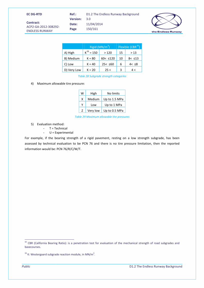
EC DG-RTD Contract: ACP2-GA-2012-308292- ENDLESS RUNWAY
Ref.: D1.2 The Endless Runway Background Version: 3.0
Date: 11/04/2014 Page 150/161
Public
D1.2 The Endless Runway Background
Rigid (MN/m3) Flexible (CBR32)
A) High K33 = 150 > 120 15 > 13
B) Medium K = 80 60< ≤120 10 8< ≤13
C) Low K = 40 25< ≤60 6 4< ≤8
D) Very Low K = 20 25 < 3 4 <
Table 28 Subgrade strength categories
4) Maximum allowable tire pressure:
W High No limits
X Medium Up to 1.5 MPa
Y Low Up to 1 MPa
Z Very low Up to 0.5 MPa
Table 29 Maximum allowable tire pressures
5) Evaluation method: - T = Technical - U = Experimental
For example, if the bearing strength of a rigid pavement, resting on a low strength subgrade, has been
assessed by technical evaluation to be PCN 76 and there is no tire pressure limitation, then the reported
information would be: PCN 76/R/C/W/T.
32 CBR (California Bearing Ratio): is a penetration test for evaluation of the mechanical strength of road subgrades and basecourses. 33 K: Westergaard subgrade reaction module, in MN/m3.
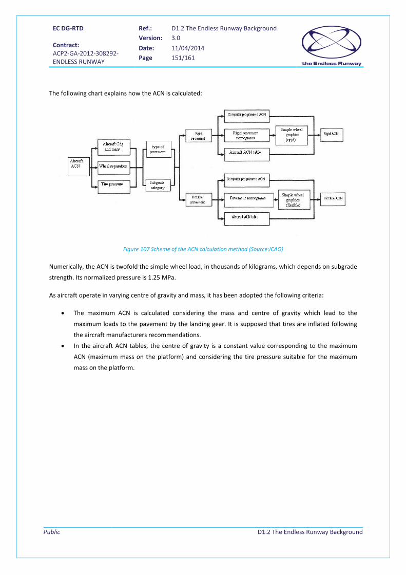
EC DG-RTD Contract: ACP2-GA-2012-308292- ENDLESS RUNWAY
Ref.: D1.2 The Endless Runway Background Version: 3.0
Date: 11/04/2014 Page 151/161
Public
D1.2 The Endless Runway Background
The following chart explains how the ACN is calculated:
Figure 107 Scheme of the ACN calculation method (Source:ICAO)
Numerically, the ACN is twofold the simple wheel load, in thousands of kilograms, which depends on subgrade
strength. Its normalized pressure is 1.25 MPa.
As aircraft operate in varying centre of gravity and mass, it has been adopted the following criteria:
• The maximum ACN is calculated considering the mass and centre of gravity which lead to the
maximum loads to the pavement by the landing gear. It is supposed that tires are inflated following
the aircraft manufacturers recommendations.
• In the aircraft ACN tables, the centre of gravity is a constant value corresponding to the maximum
ACN (maximum mass on the platform) and considering the tire pressure suitable for the maximum
mass on the platform.

EC DG-RTD Contract: ACP2-GA-2012-308292- ENDLESS RUNWAY
Ref.: D1.2 The Endless Runway Background Version: 3.0
Date: 11/04/2014 Page 152/161
Public
D1.2 The Endless Runway Background
Appendix D Intermediate computation
Appendix D.1 Equations of the circular banked track with friction The system to be solved is the following:
�𝑁𝑠𝑖𝑛𝜃 = 𝑚𝑉2
𝑅− 𝐹𝑐𝑜𝑠𝜃
𝑁𝑐𝑜𝑠𝜃 = 𝑚𝑔 + 𝐹𝑠𝑖𝑛𝜃𝐹 = 𝜇𝑁
(26)(27)(28)
We are looking for an expression of tanθ as a function of V, µ and R, and for an expression of V as a function of
R, µ and tanθ.
Multiplying equation (26) by R, we get:
𝑅𝑁𝑠𝑖𝑛𝜃 = 𝑚𝑉2 − 𝑅𝐹𝑐𝑜𝑠𝜃
Combined with equation (28), we obtain:
𝑅𝑁𝑠𝑖𝑛𝜃 = 𝑚𝑉2 − 𝑅𝜇𝑁𝑐𝑜𝑠𝜃
Using equation (27), previous equation becomes:
𝑅𝑁𝑠𝑖𝑛𝜃 = 𝑚𝑉2 − 𝑅𝜇(𝑚𝑔 + 𝐹𝑠𝑖𝑛𝜃)
⇒ 𝑅(𝑁 + 𝜇𝐹)𝑠𝑖𝑛𝜃 = 𝑚𝑉2 − 𝜇𝑅𝑔𝑚
⇒ 𝑠𝑖𝑛𝜃 = 𝑚(𝑉2−𝜇𝑅𝑔)𝑅(𝑁+𝜇𝐹) (29)
We proceed in a similar way with equation (29) combined with equations (29) and (28) :
𝑁𝑐𝑜𝑠𝜃 = 𝑚𝑔 + 𝜇𝑁𝑠𝑖𝑛𝜃 = 𝑚𝑔 + 𝜇 �𝑚𝑉2
𝑅− 𝐹𝑐𝑜𝑠𝜃�
Multiplying previous equation by R, we get:
𝑁𝑅𝑐𝑜𝑠𝜃 = 𝑅𝑚𝑔 + 𝜇𝑚𝑉2 − 𝑅𝜇𝐹𝑐𝑜𝑠𝜃
⇒ 𝑅(𝑁 + 𝜇𝐹)𝑐𝑜𝑠𝜃 = 𝑚(𝑅𝑔 + 𝜇𝑉2)
⇒ 𝑐𝑜𝑠𝜃 = 𝑚(𝑅𝑔+𝜇𝑉2)𝑅(𝑁+𝜇𝐹) (30)
Considering that cos 𝜃 ≠ 0 (𝜃 ≠ 𝜋2
[𝜋]), we divide (29) by (30):

EC DG-RTD Contract: ACP2-GA-2012-308292- ENDLESS RUNWAY
Ref.: D1.2 The Endless Runway Background Version: 3.0
Date: 11/04/2014 Page 153/161
Public
D1.2 The Endless Runway Background
𝑡𝑎𝑛𝜃 = 𝑠𝑖𝑛𝜃𝑐𝑜𝑠𝜃
= 𝑉2−𝜇𝑅𝑔
𝑅𝑔+𝜇𝑉2 (31)
In order to obtain the expression of V, we proceed by multiplying (31) by 𝑅𝑔 + 𝜇𝑉2.
(31) ⇒ 𝑅𝑔𝑡𝑎𝑛𝜃 + 𝜇𝑉2𝑡𝑎𝑛𝜃 = 𝑉2 − 𝜇𝑅𝑔
⇒ 𝑅𝑔(𝑡𝑎𝑛𝜃 + 𝜇) = 𝑉2(1 − 𝜇𝑡𝑎𝑛𝜃)
Considering that 1 − 𝜇𝑡𝑎𝑛𝜃 ≠ 0, we finally get:
𝑉2 = 𝑅𝑔 (𝑡𝑎𝑛𝜃+𝜇)(1−𝜇𝑡𝑎𝑛𝜃)
(32)
Appendix D.2 Resolution of the primitive for the computing of Ymax We want to integrate the following function between 0 and X:
𝑦 =1𝑔𝑅0
�(𝐾𝑥)2
�1 + 𝑥𝑅0�
𝑋
0𝑑𝑥
We can rewrite it:
𝑦 =𝐾2
𝑔𝑅0�
𝑥2
�1 + 𝑥𝑅0�
𝑋
0𝑑𝑥
Let’s transform it into an easy-to-solve integral.
We have:
𝑥2
�1 + 𝑥𝑅0�
= 𝑅02� 𝑥𝑅0
�2
1 + 𝑥𝑅0
= 𝑅02�� 𝑥𝑅0
+ 1�2− 2𝑥𝑅0
− 1�
1 + 𝑥𝑅0
= 𝑅02��1 + 𝑥
𝑅0�2− 2 � 𝑥𝑅0
+ 1� + 1�
1 + 𝑥𝑅0
= 𝑅02 ��1 +𝑥𝑅0� − 2 +
1
� 𝑥𝑅0+ 1�
�
A change of variable u = 1 + 𝑥𝑅0
allows to easily compute a primitive of 1+ 𝑥𝑅0
.
𝑑𝑢 = 𝑑𝑡/𝑅0 ⟹ 𝑑𝑡 = 𝑅0𝑑𝑢
��1 +𝑥𝑅0� 𝑑𝑥 = �𝑢𝑅0𝑑𝑢 = 𝑅0
𝑢2
2+ 𝐾1 = 𝑅0
�1 + 𝑥𝑅0�2
2+ 𝐾1
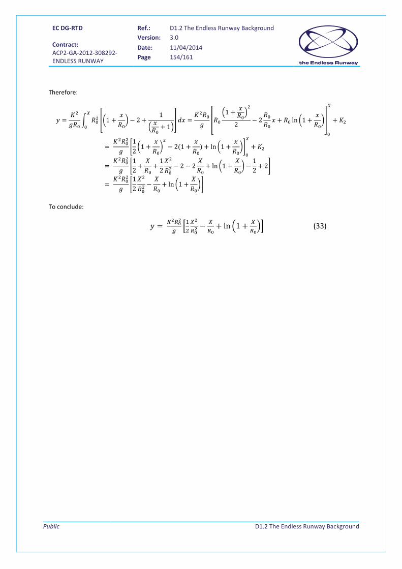
EC DG-RTD Contract: ACP2-GA-2012-308292- ENDLESS RUNWAY
Ref.: D1.2 The Endless Runway Background Version: 3.0
Date: 11/04/2014 Page 154/161
Public
D1.2 The Endless Runway Background
Therefore:
𝑦 =𝐾2
𝑔𝑅0� 𝑅02 ��1 +
𝑥𝑅0� − 2 +
1
� 𝑥𝑅0+ 1�
�𝑋
0𝑑𝑥 =
𝐾2𝑅0𝑔
�𝑅0�1 + 𝑥
𝑅0�2
2− 2
𝑅0𝑅0𝑥 + 𝑅0 ln �1 +
𝑥𝑅0��
0
𝑋
+ 𝐾2
= 𝐾2𝑅02
𝑔�12�1 +
𝑥𝑅0�2− 2(1 +
𝑥𝑅0
) + ln �1 +𝑥𝑅0��
0
𝑋
+ 𝐾2
= 𝐾2𝑅02
𝑔�12
+𝑋𝑅0
+12𝑋2
𝑅02− 2 − 2
𝑋𝑅0
+ ln �1 +𝑋𝑅0� −
12
+ 2�
= 𝐾2𝑅02
𝑔�12𝑋2
𝑅02−𝑋𝑅0
+ ln �1 +𝑋𝑅0��
To conclude:
𝑦 = 𝐾2𝑅02
𝑔�12𝑋2
𝑅02− 𝑋
𝑅0+ ln �1 + 𝑋
𝑅0�� (33)
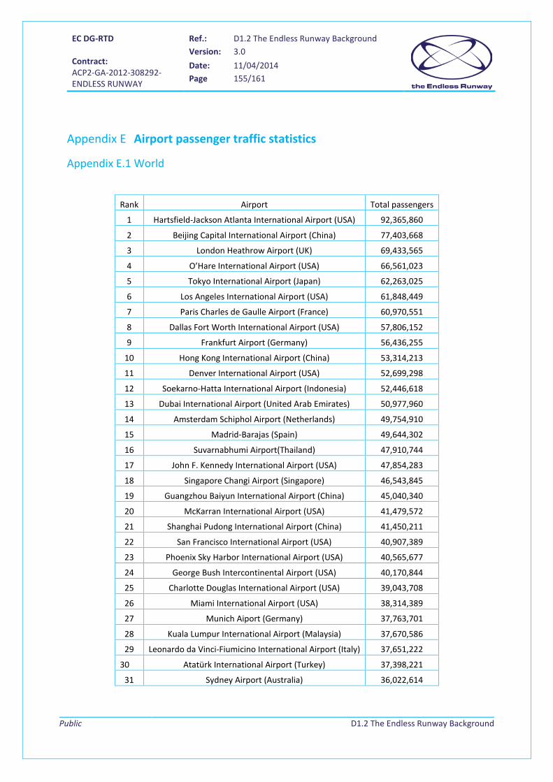
EC DG-RTD Contract: ACP2-GA-2012-308292- ENDLESS RUNWAY
Ref.: D1.2 The Endless Runway Background Version: 3.0
Date: 11/04/2014 Page 155/161
Public
D1.2 The Endless Runway Background
Appendix E Airport passenger traffic statistics
Appendix E.1 World
Rank Airport Total passengers
1 Hartsfield-Jackson Atlanta International Airport (USA) 92,365,860
2 Beijing Capital International Airport (China) 77,403,668
3 London Heathrow Airport (UK) 69,433,565
4 O’Hare International Airport (USA) 66,561,023
5 Tokyo International Airport (Japan) 62,263,025
6 Los Angeles International Airport (USA) 61,848,449
7 Paris Charles de Gaulle Airport (France) 60,970,551
8 Dallas Fort Worth International Airport (USA) 57,806,152
9 Frankfurt Airport (Germany) 56,436,255
10 Hong Kong International Airport (China) 53,314,213
11 Denver International Airport (USA) 52,699,298
12 Soekarno-Hatta International Airport (Indonesia) 52,446,618
13 Dubai International Airport (United Arab Emirates) 50,977,960
14 Amsterdam Schiphol Airport (Netherlands) 49,754,910
15 Madrid-Barajas (Spain) 49,644,302
16 Suvarnabhumi Airport(Thailand) 47,910,744
17 John F. Kennedy International Airport (USA) 47,854,283
18 Singapore Changi Airport (Singapore) 46,543,845
19 Guangzhou Baiyun International Airport (China) 45,040,340
20 McKarran International Airport (USA) 41,479,572
21 Shanghai Pudong International Airport (China) 41,450,211
22 San Francisco International Airport (USA) 40,907,389
23 Phoenix Sky Harbor International Airport (USA) 40,565,677
24 George Bush Intercontinental Airport (USA) 40,170,844
25 Charlotte Douglas International Airport (USA) 39,043,708
26 Miami International Airport (USA) 38,314,389
27 Munich Aiport (Germany) 37,763,701
28 Kuala Lumpur International Airport (Malaysia) 37,670,586
29 Leonardo da Vinci-Fiumicino International Airport (Italy) 37,651,222
30 Atatürk International Airport (Turkey) 37,398,221
31 Sydney Airport (Australia) 36,022,614
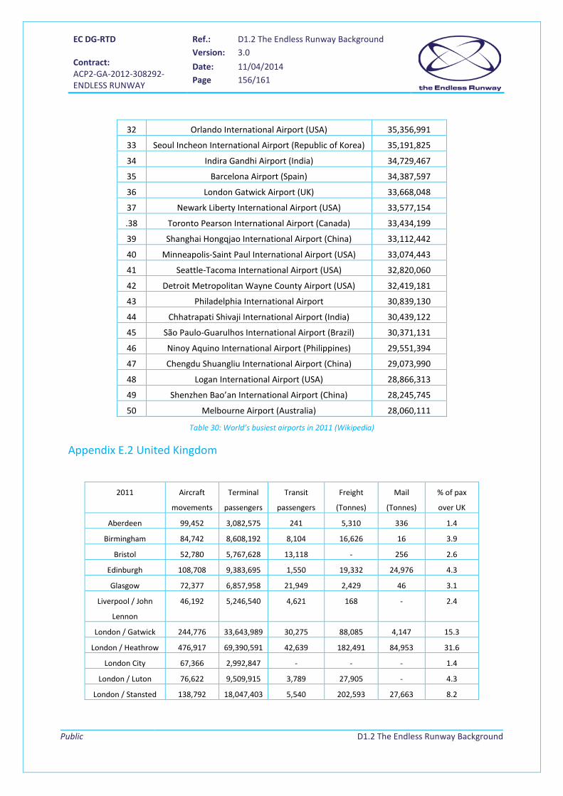
EC DG-RTD Contract: ACP2-GA-2012-308292- ENDLESS RUNWAY
Ref.: D1.2 The Endless Runway Background Version: 3.0
Date: 11/04/2014 Page 156/161
Public
D1.2 The Endless Runway Background
32 Orlando International Airport (USA) 35,356,991
33 Seoul Incheon International Airport (Republic of Korea) 35,191,825
34 Indira Gandhi Airport (India) 34,729,467
35 Barcelona Airport (Spain) 34,387,597
36 London Gatwick Airport (UK) 33,668,048
37 Newark Liberty International Airport (USA) 33,577,154
.38 Toronto Pearson International Airport (Canada) 33,434,199
39 Shanghai Hongqjao International Airport (China) 33,112,442
40 Minneapolis-Saint Paul International Airport (USA) 33,074,443
41 Seattle-Tacoma International Airport (USA) 32,820,060
42 Detroit Metropolitan Wayne County Airport (USA) 32,419,181
43 Philadelphia International Airport 30,839,130
44 Chhatrapati Shivaji International Airport (India) 30,439,122
45 São Paulo-Guarulhos International Airport (Brazil) 30,371,131
46 Ninoy Aquino International Airport (Philippines) 29,551,394
47 Chengdu Shuangliu International Airport (China) 29,073,990
48 Logan International Airport (USA) 28,866,313
49 Shenzhen Bao’an International Airport (China) 28,245,745
50 Melbourne Airport (Australia) 28,060,111
Table 30: World’s busiest airports in 2011 (Wikipedia)
Appendix E.2 United Kingdom
2011 Aircraft
movements
Terminal
passengers
Transit
passengers
Freight
(Tonnes)
(Tonnes)
% of pax
over UK
Aberdeen 99,452 3,082,575 241 5,310 336 1.4
Birmingham 84,742 8,608,192 8,104 16,626 16 3.9
Bristol 52,780 5,767,628 13,118 - 256 2.6
Edinburgh 108,708 9,383,695 1,550 19,332 24,976 4.3
Glasgow 72,377 6,857,958 21,949 2,429 46 3.1
Liverpool / John
Lennon
46,192 5,246,540 4,621 168 - 2.4
London / Gatwick 244,776 33,643,989 30,275 88,085 4,147 15.3
London / Heathrow 476,917 69,390,591 42,639 182,491 84,953 31.6
London City 67,366 2,992,847 - - - 1.4
London / Luton 76,622 9,509,915 3,789 27,905 - 4.3
London / Stansted 138,792 18,047,403 5,540 202,593 27,663 8.2

EC DG-RTD Contract: ACP2-GA-2012-308292- ENDLESS RUNWAY
Ref.: D1.2 The Endless Runway Background Version: 3.0
Date: 11/04/2014 Page 157/161
Public
D1.2 The Endless Runway Background
Manchester 158,262 18,806,655 86,101 107,415 1,125 8.6
Newcastle 45,121 4,336,304 9,966 3,059 8,553 2.0
Southampton 41,280 1,761,971 115 132 - 0.8
Table 31: Airport traffic in UK in 2011. All data belongs to international airports34
Appendix E.3 Spain AENA (“Aeropuertos Españoles y Navegación Aérea”), the organization in charge of civil airports and civil
navigation in Spain, currently manages 49 airports. The Economic European Community classifies 33 of them
as international. AENA distributes the different airports into eight categories:
• Hubs (Madrid and Barcelona)
• Big Insular Airports (Palma de Mallorca, Gran Canaria, Tenerife Norte, Tenerife Sur)
• Regional Airports (Málaga, Alicante, Bilbao, Santiago, Sevilla, Valencia)
• Medium Insular Airports (Ibiza, Menorca, Fuerteventura, Lanzarote)
• Small Airports (peninsular airports with less than 600,000 passengers annually)
• Small Insular Airports (Gomera, Hierro, La Palma, Melilla)
• Other airports (general aviation, airbases, training centres)
The following table shows the annual passengers for the different types in 2011:
Airport type Airport Passengers
Hubs Madrid/Barajas 49,671,270
Barcelona/El Prat 34,398,226
Big
Insular
Airports
Palma de Mallorca 22,726,707
Gran Canaria 10,538,829
Tenerife Norte 4,095,103
Tenerife Sur 8,656,487
Regional
Airports
Málaga/Costa del Sol 12,823,117
Alicante 9,913,731
Valencia 4,979,511
Sevilla 4,959,359
Bilbao 4,046,172
Santiago 2,464,330
Medium
Insular
Airports
Ibiza 5,643,180
Lanzarote 5,543,744
Fuerteventura 4,948,018
Menorca 2,576,200
34 Source : http://www.caa.co.uk/default.aspx?catid=80&pagetype=88&sglid=3&fld=2011Annual
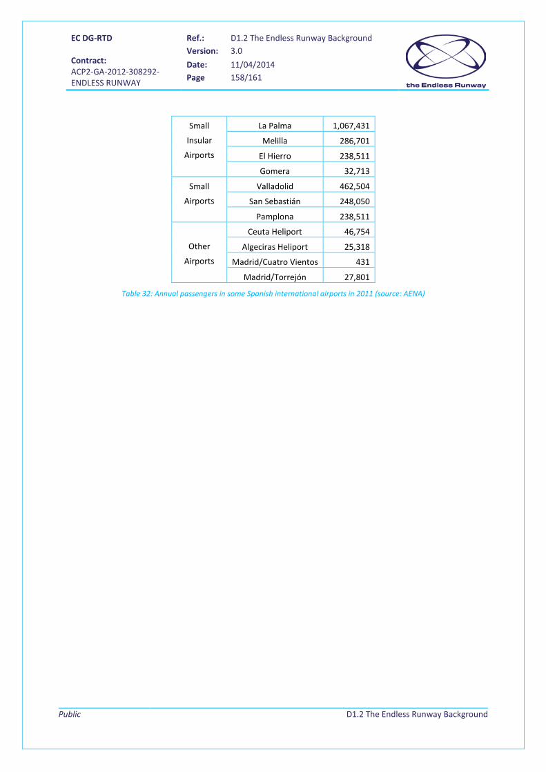
EC DG-RTD Contract: ACP2-GA-2012-308292- ENDLESS RUNWAY
Ref.: D1.2 The Endless Runway Background Version: 3.0
Date: 11/04/2014 Page 158/161
Public
D1.2 The Endless Runway Background
Small
Insular
Airports
La Palma 1,067,431
Melilla 286,701
El Hierro 238,511
Gomera 32,713
Small
Airports
Valladolid 462,504
San Sebastián 248,050
Pamplona 238,511
Other
Airports
Ceuta Heliport 46,754
Algeciras Heliport 25,318
Madrid/Cuatro Vientos 431
Madrid/Torrejón 27,801
Table 32: Annual passengers in some Spanish international airports in 2011 (source: AENA)

EC DG-RTD Contract: ACP2-GA-2012-308292- ENDLESS RUNWAY
Ref.: D1.2 The Endless Runway Background Version: 3.0
Date: 11/04/2014 Page 159/161
Public
D1.2 The Endless Runway Background
Appendix F Aeronautical charts Departure chart
Figure 108 Departure chart for SID (AIP Hamburg, Germany)
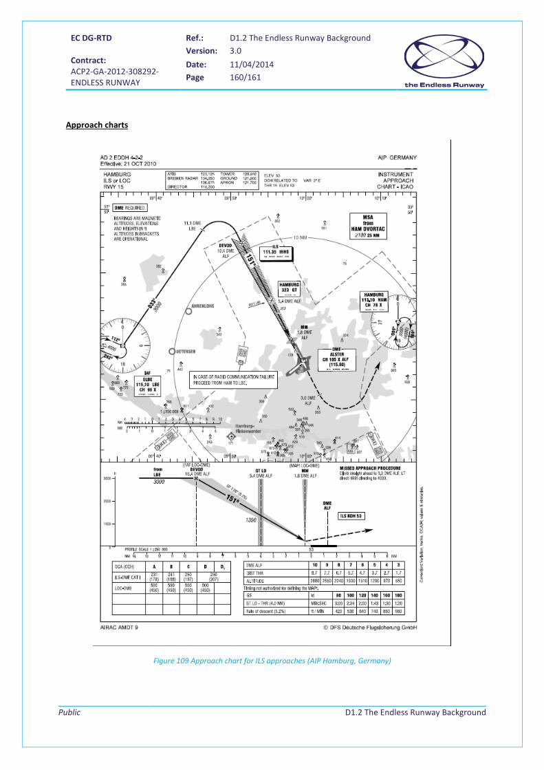
EC DG-RTD Contract: ACP2-GA-2012-308292- ENDLESS RUNWAY
Ref.: D1.2 The Endless Runway Background Version: 3.0
Date: 11/04/2014 Page 160/161
Public
D1.2 The Endless Runway Background
Approach charts
Figure 109 Approach chart for ILS approaches (AIP Hamburg, Germany)
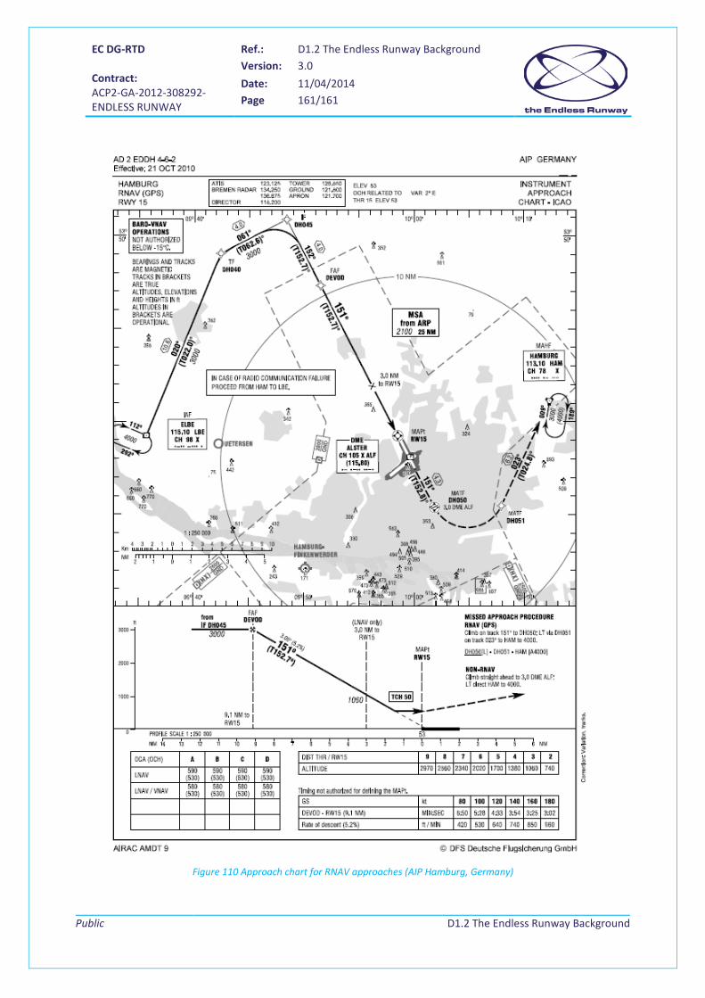
EC DG-RTD Contract: ACP2-GA-2012-308292- ENDLESS RUNWAY
Ref.: D1.2 The Endless Runway Background Version: 3.0
Date: 11/04/2014 Page 161/161
Public
D1.2 The Endless Runway Background
Figure 110 Approach chart for RNAV approaches (AIP Hamburg, Germany)