d-statcom with positive-sequence admittance and ... on industrial electronics, vol.60,no.4,april2013...
TRANSCRIPT

IEEE TRANSACTIONS ON INDUSTRIAL ELECTRONICS, VOL. 60, NO. 4, APRIL 2013 1417
D-STATCOM With Positive-Sequence Admittanceand Negative-Sequence Conductance to MitigateVoltage Fluctuations in High-Level Penetration
of Distributed-Generation SystemsTzung-Lin Lee, Member, IEEE, Shang-Hung Hu, Student Member, IEEE, and Yu-Hung Chan
Abstract—Voltage fluctuations resulting from variable outputpower of renewable energy sources are strictly challenging powerquality in distributed-generation systems. This paper presentsa control method for distributed static synchronous compen-sator (D-STATCOM) to alleviate variation of both positive- andnegative-sequence voltages. The D-STATCOM simultaneouslyoperates as fundamental positive-sequence admittance and fun-damental negative-sequence conductance to restore the positive-sequence voltage to the nominal value as well as reduce thenegative-sequence voltage to an allowable level. Both admittanceand conductance are dynamically tuned to improve voltage-regulation performances in response to load changes and powervariation of renewable sources. A proportional–resonant currentregulator with selectively harmonic compensation is realized tocontrol the fundamental current of the D-STATCOM as well asreduce the harmonic current, which could be an advantage inpractical applications due to high voltage distortion in low-voltagemicrogrids. Voltage-regulation performances are discussed fordifferent D-STATCOM locations as well as different D-STATCOMcurrents. Computer simulations and laboratory tests validateeffectiveness.
Index Terms—Distributed STATCOM (D-STATCOM), micro-grid, voltage fluctuations, voltage imbalance.
I. INTRODUCTION
G LOBAL concerns about the environment and fossil fuelscontinue to advance the development of renewable en-
ergy systems, such as wind turbines, photovoltaics, fuel cells,etc. The microgrid concept was proposed to intelligently coor-dinate various renewable energy sources (RESs) into distribu-tion networks for both grid-connected and islanding operations[1], [2]. Increasing the use of RESs could help relieve networkcongestion, reduce system losses, and defer infrastructure in-vestments. These issues have received much attention recently,and numerous projects have been commissioned to demonstrateand evaluate functionality of microgrids by worldwide researchorganizations, for example, Consortium for Electric Reliability
Manuscript received February 23, 2011; revised May 6, 2011 and July 27,2011; accepted August 12, 2011. Date of publication August 30, 2011; date ofcurrent version November 22, 2012. This work was supported by the NationalScience Council of Taiwan under Grant NSC 99-3113-P-214-001.
The authors are with the Department of Electrical Engineering, National SunYat-Sen University, Kaohsiung 80424, Taiwan (e-mail: [email protected]; [email protected]; [email protected]).
Color versions of one or more of the figures in this paper are available onlineat http://ieeexplore.ieee.org.
Digital Object Identifier 10.1109/TIE.2011.2166233
Technology Solutions [3] and New Energy and Industrial Tech-nology Development Organization [4].
Conventionally, voltage fluctuations in the power systemmainly result from impedance of transmission lines, loadingtypes, and uneven distribution of single-phase loads. Thescenarios become much severer in the low-voltage microgridsystem due to reverse power flow contributed by distributedgenerations (DGs) in either three- or single-phase connec-tion [5]. Voltage fluctuations cause system losses, capacityreduction, transformer overloading, and motor overheating, andeven results in output limitation of DGs, nuisance tripping ofprotected devices, and malfunction of sensitive equipment.According to IEEE Std 1547.2-2008 [6], voltage fluctuationsare limited to ±5% as RESs are paralleled to low-voltage sys-tems. Voltage imbalance measured by %Unbalance or %VUFkept below 2.0%–3.0% is acceptable for both manufacturesand utility, where %Unbalance and %VUF are defined asthe percentage of maximum deviation from the average valueand the ratio of the negative-sequence voltage to the positive-sequence voltage, respectively [7]. Therefore, voltage regula-tion is absolutely needed to allow more DGs to join grid-connected operation.
Voltage regulation in the power system could be realized byusing an on-load tap changer (OLTC) or a static VAR compen-sator (SVC) at substations, and a step voltage regulator or aswitched capacitor on feeders. With the help of the so-calledoptimal or intelligent control on all devices, the voltage profilecould be improved on a real-time base [8], [9]. Thanks to theadvancement of semiconductor technologies, voltage-source-converter-based solutions, such as static synchronous com-pensator (STATCOM), unified power flow controller (UPFC),distributed STATCOM (D-STATCOM), and active power fil-ter (APF), become viable in practical applications [10]–[14].STATCOM technology has been extensively studied and devel-oped in transmission systems to regulate voltage by adjustingits reactive power into the power system, whereas UPFC wasdesigned to control real- and reactive-power flows between twosubstations. On the other hand, D-STATCOM and APF aresuitable for power quality improvement of the distributed powersystem, such as harmonic compensation, harmonic damping,and reactive-power compensation.
A D-STATCOM for compensating voltage fluctuations ofload bus was presented [15]. In this paper, voltage regulation
0278-0046/$26.00 © 2011 IEEE

1418 IEEE TRANSACTIONS ON INDUSTRIAL ELECTRONICS, VOL. 60, NO. 4, APRIL 2013
Fig. 1. Simplified Thévenin equivalent circuit of the DG system.
was conducted by injecting reactive current into the utility.However, regulation performances may suffer from controllingerror due to either imbalanced voltage or harmonic distor-tion. In [16], fundamental positive- and negative-sequencecurrents were separately controlled to improve the voltage-regulation performances of the D-STATCOM. However,negative-sequence compensation may not work properly as theimbalanced source is nearby. A harmonic damping active filterwas proposed to restore the voltage swell due to distributed gen-erators [17]. However, discussions were limited in controllingpositive-sequence voltage only. The concept of inverter-basedRESs with functionality of VAr supporting was presented to ac-complish voltage regulation locally [18]–[22]. Although RESsare currently not allowed to actively regulate the voltage at thepoint of common coupling (PCC) by IEEE Std 1547.2-2008,this operation may be viable in the future because supplyingreactive power by customers with tariff reimbursement willbenefit the utility for reducing equipment investment as well[23]–[25].
Compensating voltage fluctuations in DG systems by aD-STATCOM was presented in [26]. In this paper, we presentextended simulations and discussions as well as experimentalverification. The proposed D-STATCOM realizes positive-sequence admittance and negative-sequence conductanceto regulate positive-sequence voltage as well as suppressnegative-sequence voltage. Both positive-sequence admittanceand negative-sequence conductance are dynamically adjustedaccording to positive-sequence voltage deviation andimbalanced-voltage percentage. Therefore, voltage qualitycan be maintained at an allowable level in case of variationof DGs or loads. A proportional–resonant (PR) currentregulator with selective harmonic compensation [27], [28]is implemented to control the fundamental current of theD-STATCOM as well as reduce harmonic current due tohigh voltage distortion in low-voltage networks. Theoreticalanalysis of voltage regulation with supporting results fromsimulations and experiments validates the proposed approach.
II. VOLTAGE VARIATION IN THE DG SYSTEM
Voltage fluctuations resulting from reverse power flow con-tributed by DGs have been reported [4], [5], [29]. In this section,a simplified Thévenin equivalent circuit of the DG systemshown in Fig. 1 is established to address this phenomenon.Source voltage Ep is assumed to contain a positive-sequencecomponent only, and line impedance is assumed to be equalto Z = R + jXL for both positive and negative sequences.Positive-sequence current IGp represents the equivalent realpower supplied from the distributed generator or consumed by
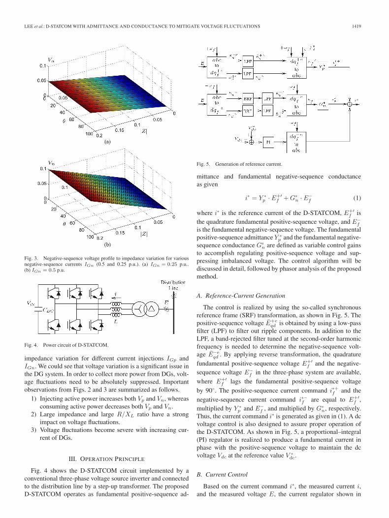
Fig. 2. Positive-sequence voltage profile to impedance variation for variousIGp [1.0, 0.5, −0.5, and −1.0 per unit (p.u.)]. (a) IGp = 0.5 p.u.. (b) IGp =1.0 p.u.. (c) IGp = −0.5 p.u.. (d) IGp = −1.0 p.u..
the load, while negative-sequence current IGn is contributed bya single-phase generator or load. Figs. 2 and 3 show positive-sequence voltage Vp and negative-sequence voltage Vn with
LEE et al.: D-STATCOM WITH ADMITTANCE AND CONDUCTANCE TO MITIGATE VOLTAGE FLUCTUATIONS 1419
Fig. 3. Negative-sequence voltage profile to impedance variation for variousnegative-sequence currents IGn (0.5 and 0.25 p.u.). (a) IGn = 0.25 p.u..(b) IGn = 0.5 p.u.
Fig. 4. Power circuit of D-STATCOM.
impedance variation for different current injections IGp andIGn. We could see that voltage variation is a significant issue inthe DG system. In order to collect more power from DGs, volt-age fluctuations need to be absolutely suppressed. Importantobservations from Figs. 2 and 3 are summarized as follows.
1) Injecting active power increases both Vp and Vn, whereasconsuming active power decreases both Vp and Vn.
2) Large impedance and large R/XL ratio have a strongimpact on voltage fluctuations.
3) Voltage fluctuations become severe with increasing cur-rent of DGs.
III. OPERATION PRINCIPLE
Fig. 4 shows the D-STATCOM circuit implemented by aconventional three-phase voltage source inverter and connectedto the distribution line by a step-up transformer. The proposedD-STATCOM operates as fundamental positive-sequence ad-
Fig. 5. Generation of reference current.
mittance and fundamental negative-sequence conductanceas given
i∗ = Y ∗p · E+′
f + G∗n · E−
f (1)
where i∗ is the reference current of the D-STATCOM, E+′f is
the quadrature fundamental positive-sequence voltage, and E−f
is the fundamental negative-sequence voltage. The fundamentalpositive-sequence admittance Y ∗
p and the fundamental negative-sequence conductance G∗
n are defined as variable control gainsto accomplish regulating positive-sequence voltage and sup-pressing imbalanced voltage. The control algorithm will bediscussed in detail, followed by phasor analysis of the proposedmethod.
A. Reference-Current Generation
The control is realized by using the so-called synchronousreference frame (SRF) transformation, as shown in Fig. 5. Thepositive-sequence voltage E+e
qd is obtained by using a low-passfilter (LPF) to filter out ripple components. In addition to theLPF, a band-rejected filter tuned at the second-order harmonicfrequency is needed to determine the negative-sequence volt-age E−e
qd . By applying reverse transformation, the quadrature
fundamental positive-sequence voltage E+′f and the negative-
sequence voltage E−f in the three-phase system are available,
where E+′f lags the fundamental positive-sequence voltage
by 90◦. The positive-sequence current command i∗+f and the
negative-sequence current command i∗−f are equal to E+′f ,
multiplied by Y ∗p and E−
f , and multiplied by G∗n, respectively.
Thus, the current command i∗ is generated as given in (1). A dcvoltage control is also designed to assure proper operation ofthe D-STATCOM. As shown in Fig. 5, a proportional–integral(PI) regulator is realized to produce a fundamental current inphase with the positive-sequence voltage to maintain the dcvoltage Vdc at the reference value V ∗
dc.
B. Current Control
Based on the current command i∗, the measured current i,and the measured voltage E, the current regulator shown in

1420 IEEE TRANSACTIONS ON INDUSTRIAL ELECTRONICS, VOL. 60, NO. 4, APRIL 2013
Fig. 6. Current control.
Fig. 7. Current-loop block diagram.
Fig. 8. Tuning control of Y ∗p and G∗
n.
Fig. 6 produces the voltage command v∗ for space vectorpulsewidth modulation (PWM) control of the inverter. Thetransfer functions Hf (s) and Hh(s) are defined as
Hf (s) = kp +2Ki,fξωfs
s2 + 2ξωfs + ω2f
Hh(s) =∑
h
2Ki,hξωhs
s2 + 2ξωhs + ω2h
(2)
where kp represents a proportional gain; ωf and Ki,f arethe fundamental frequency and its integral gain, respectively;and ωh and Ki,h represent the harmonic frequency and itsintegral gain, respectively. The current regulation is tuned withdamping ratio ξ to introduce a narrow gain peak centered atthe fundamental frequency for fundamental current trackingand also to produce various narrow gain peaks at the harmonicfrequencies to reduce current distortion. The current-loop blockdiagram is shown in Fig. 7, in which digital signal processingdelay and PWM delay are considered. T represents a samplingperiod. Accordingly, current-tracking capability and current-loop stability can be simply evaluated by using Bode plots ofopen- and closed-loop transfer functions. Further discussionson current control are provided in the simulation section.
C. Tuning Control
Fig. 8 shows the tuning control of both Y ∗p and G∗
n. |E+f |
and |E−f | are defined as (3). They can be approximately cal-
culated by using LPFs and SQRT operation, where LPFs aredesigned with cutoff frequency ωc = 10 Hz to filter out ripple
Fig. 9. Thévenin equivalent circuit with the D-STATCOM compensatingpositive-sequence current ICp and negative-sequence current ICn.
components in the calculation. Then, a PI regulator is realizedto generate Y ∗
p to maintain |E+f | at the nominal value |E+
f |∗.Similarly, imbalanced voltage could be suppressed and main-tained at an allowable level by controlling G∗
n. In this paper, weadopt %VUF (percentage of voltage imbalance factor) to assessthe level of imbalanced voltage. It is defined as the ratio of thenegative-sequence voltage to the positive-sequence voltage andis expressed in (4)
∣∣∣E+f
∣∣∣ =
√∫ t+T
t
(E+e
q (t)2 + E+ed (t)2
)T
dt
∣∣∣E−f
∣∣∣ =
√∫ t+T
t
(E−e
q (t)2 + E−ed (t)2
)T
dt (3)
%VUF =
∣∣∣E−f
∣∣∣∣∣∣E+f
∣∣∣ · 100%. (4)
Basically, there are three control loops in the proposedmethod. The bandwidth of the current control loop is thehighest one, which is dependent on the switching frequency ofthe inverter. The tuning loops of both admittance and conduc-tance are to generate the current commands to improve powerquality, so their bandwidths are lower than that of the currentloop. In practice, their PI parameters are tuned to control bothadmittance and conductance with suitable transient response aswell as zero steady-state error. On the other hand, the voltageon the dc capacitor will fluctuate due to inverter losses andconductance for suppressing imbalanced voltage. The lower thedc capacitance, the larger fluctuation will happen. Generally,due to large capacitance, the bandwidth of dc voltage control islowest in the system.
D. Phasor Analysis
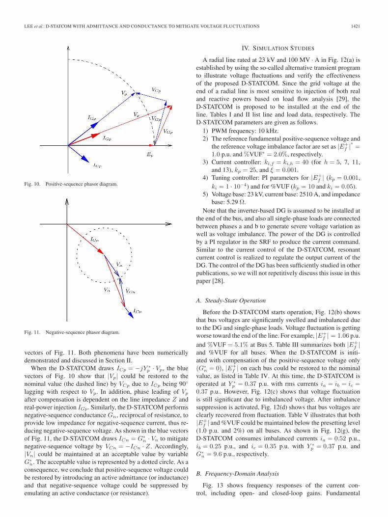
In this section, D-STATCOM operation will be discussedbased on phasor analysis [12]. Fig. 9 shows the Théveninequivalent circuit with the proposed D-STATCOM compensat-ing positive-sequence current ICp as well as negative-sequencecurrent ICn. Before the D-STATCOM starts operation, positive-sequence voltage is swelled up, as shown in the red vectors ofFig. 10. |Vp| is obviously larger than |Ep|. This results fromthe voltage drop VGp on line impedance Z = R + jXL whenIGp is injected into the grid. On the other hand, the negative-sequence current IGn flowing on the line impedance Z causesthe negative-sequence voltage drop Vn, as shown in the red
LEE et al.: D-STATCOM WITH ADMITTANCE AND CONDUCTANCE TO MITIGATE VOLTAGE FLUCTUATIONS 1421
Fig. 10. Positive-sequence phasor diagram.
Fig. 11. Negative-sequence phasor diagram.
vectors of Fig. 11. Both phenomena have been numericallydemonstrated and discussed in Section II.
When the D-STATCOM draws ICp = −jY ∗p · Vp, the blue
vectors of Fig. 10 show that |Vp| could be restored to thenominal value (the dashed line) by VCp due to ICp being 90◦
lagging with respect to Vp. In addition, phase leading of Vp
after compensation is dependent on the line impedance Z andreal-power injection IGp. Similarly, the D-STATCOM performsnegative-sequence conductance Gn, reciprocal of resistance, toprovide low impedance for negative-sequence current, thus re-ducing negative-sequence voltage. As shown in the blue vectorsof Fig. 11, the D-STATCOM draws ICn = G∗
n · Vn to mitigatenegative-sequence voltage by VCn = −ICn · Z. Accordingly,|Vn| could be maintained at an acceptable value by variableG∗
n. The acceptable value is represented by a dotted circle. As aconsequence, we conclude that positive-sequence voltage couldbe restored by introducing an active admittance (or inductance)and that negative-sequence voltage could be suppressed byemulating an active conductance (or resistance).
IV. SIMULATION STUDIES
A radial line rated at 23 kV and 100 MV · A in Fig. 12(a) isestablished by using the so-called alternative transient programto illustrate voltage fluctuations and verify the effectivenessof the proposed D-STATCOM. Since the grid voltage at theend of a radial line is most sensitive to injection of both realand reactive powers based on load flow analysis [29], theD-STATCOM is proposed to be installed at the end of theline. Tables I and II list line and load data, respectively. TheD-STATCOM parameters are given as follows.
1) PWM frequency: 10 kHz.2) The reference fundamental positive-sequence voltage and
the reference voltage imbalance factor are set as |E+f |∗ =
1.0 p.u. and %VUF∗ = 2.0%, respectively.3) Current controller: ki,f = ki,h = 40 (for h = 5, 7, 11,
and 13), kp = 25, and ξ = 0.001.4) Tuning controller: PI parameters for |E+
f | (kp = 0.001,ki = 1 · 10−4) and for %VUF (kp = 10 and ki = 0.05).
5) Voltage base: 23 kV, current base: 2510 A, and impedancebase: 5.29 Ω.
Note that the inverter-based DG is assumed to be installed atthe end of the bus, and also all single-phase loads are connectedbetween phases a and b to generate severe voltage variation aswell as voltage imbalance. The power of the DG is controlledby a PI regulator in the SRF to produce the current command.Similar to the current control of the D-STATCOM, resonantcurrent control is realized to regulate the output current of theDG. The control of the DG has been sufficiently studied in otherpublications, so we will not repetitively discuss this issue in thispaper [28].
A. Steady-State Operation
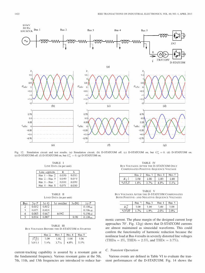
Before the D-STATCOM starts operation, Fig. 12(b) showsthat bus voltages are significantly swelled and imbalanced dueto the DG and single-phase loads. Voltage fluctuation is gettingworse toward the end of the line. For example, |E+
f | = 1.06 p.u.
and %VUF = 5.1% at Bus 5. Table III summarizes both |E+f |
and %VUF for all buses. When the D-STATCOM is initi-ated with compensation of the positive-sequence voltage only(G∗
n = 0), |E+f | on each bus could be restored to the nominal
value, as listed in Table IV. At this time, the D-STATCOM isoperated at Y ∗
p = 0.37 p.u. with rms currents ia = ib = ic =0.37 p.u.. However, Fig. 12(c) shows that voltage fluctuationis still significant due to imbalanced voltage. After imbalancesuppression is activated, Fig. 12(d) shows that bus voltages areclearly recovered from fluctuation. Table V illustrates that both|E+
f | and %VUF could be maintained below the presetting level(1.0 p.u. and 2%) on all buses. As shown in Fig. 12(g), theD-STATCOM consumes imbalanced currents ia = 0.52 p.u.,ib = 0.25 p.u., and ic = 0.35 p.u. with Y ∗
p = 0.37 p.u. andG∗
n = 9.6 p.u., respectively.
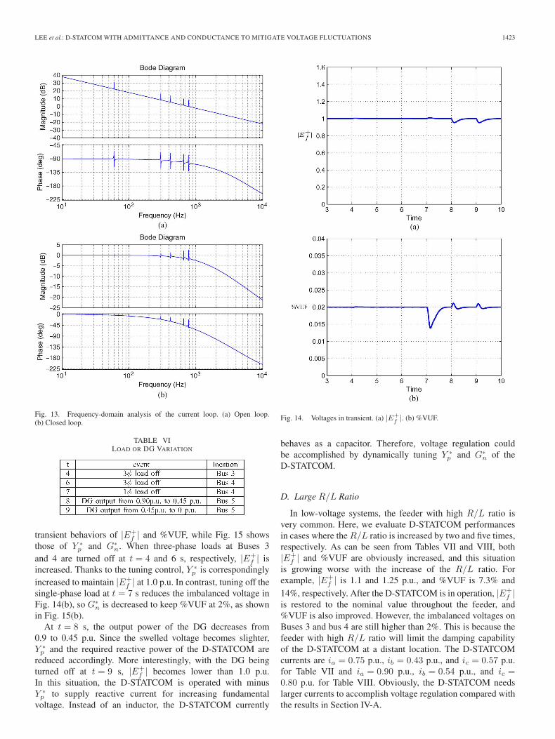
B. Frequency-Domain Analysis
Fig. 13 shows frequency responses of the current con-trol, including open- and closed-loop gains. Fundamental
1422 IEEE TRANSACTIONS ON INDUSTRIAL ELECTRONICS, VOL. 60, NO. 4, APRIL 2013
Fig. 12. Simulation circuit and test results. (a) Simulation circuit. (b) D-STATCOM off. (c) D-STATCOM on, but G∗n = 0. (d) D-STATCOM on.
(e) D-STATCOM off. (f) D-STATCOM on, but G∗n = 0. (g) D-STATCOM on.
TABLE ILINE DATA (in per unit)
TABLE IILOAD DATA (in per unit)
TABLE IIIBUS VOLTAGES BEFORE THE D-STATCOM IS STARTED
current-tracking capability is assured by a resonant gain atthe fundamental frequency. Various resonant gains at the 5th,7th, 11th, and 13th frequencies are introduced to reduce har-
TABLE IVBUS VOLTAGES AFTER THE D-STATCOM ONLY
COMPENSATES POSITIVE-SEQUENCE VOLTAGE
TABLE VBUS VOLTAGES AFTER THE D-STATCOM COMPENSATES
BOTH POSITIVE- AND NEGATIVE-SEQUENCE VOLTAGES
monic current. The phase margin of the designed current loopapproaches 70◦. Fig. 12(g) shows that D-STATCOM currentsare almost maintained as sinusoidal waveforms. This couldconfirm the functionality of harmonic reduction because thenonlinear load at Bus 4 results in severely distorted line voltages(THDa = 3%, THDb = 2.5%, and THDc = 3.7%).
C. Transient Operation
Various events are defined in Table VI to evaluate the tran-sient performances of the D-STATCOM. Fig. 14 shows the
LEE et al.: D-STATCOM WITH ADMITTANCE AND CONDUCTANCE TO MITIGATE VOLTAGE FLUCTUATIONS 1423
Fig. 13. Frequency-domain analysis of the current loop. (a) Open loop.(b) Closed loop.
TABLE VILOAD OR DG VARIATION
transient behaviors of |E+f | and %VUF, while Fig. 15 shows
those of Y ∗p and G∗
n. When three-phase loads at Buses 3and 4 are turned off at t = 4 and 6 s, respectively, |E+
f | isincreased. Thanks to the tuning control, Y ∗
p is correspondinglyincreased to maintain |E+
f | at 1.0 p.u. In contrast, tuning off thesingle-phase load at t = 7 s reduces the imbalanced voltage inFig. 14(b), so G∗
n is decreased to keep %VUF at 2%, as shownin Fig. 15(b).
At t = 8 s, the output power of the DG decreases from0.9 to 0.45 p.u. Since the swelled voltage becomes slighter,Y ∗
p and the required reactive power of the D-STATCOM arereduced accordingly. More interestingly, with the DG beingturned off at t = 9 s, |E+
f | becomes lower than 1.0 p.u.In this situation, the D-STATCOM is operated with minusY ∗
p to supply reactive current for increasing fundamentalvoltage. Instead of an inductor, the D-STATCOM currently
Fig. 14. Voltages in transient. (a) |E+f|. (b) %VUF.
behaves as a capacitor. Therefore, voltage regulation couldbe accomplished by dynamically tuning Y ∗
p and G∗n of the
D-STATCOM.
D. Large R/L Ratio
In low-voltage systems, the feeder with high R/L ratio isvery common. Here, we evaluate D-STATCOM performancesin cases where the R/L ratio is increased by two and five times,respectively. As can be seen from Tables VII and VIII, both|E+
f | and %VUF are obviously increased, and this situationis growing worse with the increase of the R/L ratio. Forexample, |E+
f | is 1.1 and 1.25 p.u., and %VUF is 7.3% and
14%, respectively. After the D-STATCOM is in operation, |E+f |
is restored to the nominal value throughout the feeder, and%VUF is also improved. However, the imbalanced voltages onBuses 3 and bus 4 are still higher than 2%. This is because thefeeder with high R/L ratio will limit the damping capabilityof the D-STATCOM at a distant location. The D-STATCOMcurrents are ia = 0.75 p.u., ib = 0.43 p.u., and ic = 0.57 p.u.for Table VII and ia = 0.90 p.u., ib = 0.54 p.u., and ic =0.80 p.u. for Table VIII. Obviously, the D-STATCOM needslarger currents to accomplish voltage regulation compared withthe results in Section IV-A.

1424 IEEE TRANSACTIONS ON INDUSTRIAL ELECTRONICS, VOL. 60, NO. 4, APRIL 2013
Fig. 15. D-STATCOM commands in transient. (a) Y ∗p . (b) G∗
n.
TABLE VIIR/L RATIO IS INCREASED BY TWO TIMES
TABLE VIIIR/L RATIO IS INCREASED BY FIVE TIMES
V. DISCUSSIONS
A. D-STATCOM Location
In this section, voltage-regulation performances are eval-uated considering the D-STATCOM at different locations.Fig. 16 shows |E+
f | and %VUF when the D-STATCOM isdeployed at Buses 2, 3, 4, and 5, respectively. At the installationpoint, both |E+
f | and %VUF can be clearly maintained at1.0 p.u. and 2%, respectively. Regulating performances onthe left side of the installation point are better than those on
Fig. 16. |E+f| and %VUF at all buses when the D-STATCOM is deployed at
Buses 2, 3, 4, and 5, respectively. (a) |E+f|. (b) %VUF.
the right side. Installing the D-STATCOM at the end of theline provides the best performances of voltage regulation onthe entire line, while voltage fluctuations could not receivemuch improvement if the D-STATCOM is closed to the voltagesource. This result absolutely complies with other studies [29],[30]. Note that imbalance suppression is no longer needed(G∗
n = 0) when the D-STATCOM is located at Bus 2 due to%VUF lower than 2%.
B. D-STATCOM Current
We will concentrate on the required D-STATCOM currentfor various levels of |E+
f |∗ and %VUF∗. For convenience, per-centage positive-sequence voltage derivation %PVD∗ is definedas (5). Thus, both positive-sequence current Ip and negative-sequence current In could be displayed in the same figure
%PVD∗ = %∣∣∣E+
f
∣∣∣∗ − 100%. (5)
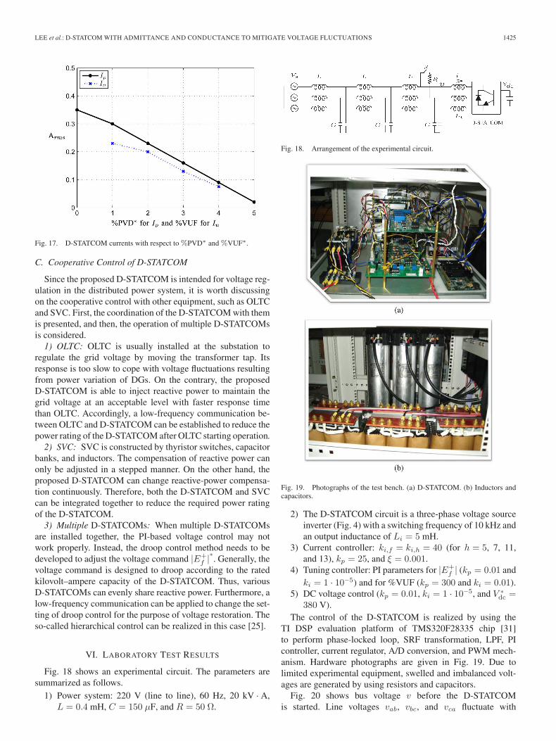
Fig. 17 shows D-STATCOM currents for %PVD∗ and %VUF∗
in the range of 0%–5%. Larger Ip and In are required tocomply with the stricter standards of %PVD∗ and %VUF∗. Thisresult could help estimate the required current rating of theD-STATCOM to reduce voltage fluctuations being up to acertain level for a given feeder.
LEE et al.: D-STATCOM WITH ADMITTANCE AND CONDUCTANCE TO MITIGATE VOLTAGE FLUCTUATIONS 1425
Fig. 17. D-STATCOM currents with respect to %PVD∗ and %VUF∗.
C. Cooperative Control of D-STATCOM
Since the proposed D-STATCOM is intended for voltage reg-ulation in the distributed power system, it is worth discussingon the cooperative control with other equipment, such as OLTCand SVC. First, the coordination of the D-STATCOM with themis presented, and then, the operation of multiple D-STATCOMsis considered.
1) OLTC: OLTC is usually installed at the substation toregulate the grid voltage by moving the transformer tap. Itsresponse is too slow to cope with voltage fluctuations resultingfrom power variation of DGs. On the contrary, the proposedD-STATCOM is able to inject reactive power to maintain thegrid voltage at an acceptable level with faster response timethan OLTC. Accordingly, a low-frequency communication be-tween OLTC and D-STATCOM can be established to reduce thepower rating of the D-STATCOM after OLTC starting operation.
2) SVC: SVC is constructed by thyristor switches, capacitorbanks, and inductors. The compensation of reactive power canonly be adjusted in a stepped manner. On the other hand, theproposed D-STATCOM can change reactive-power compensa-tion continuously. Therefore, both the D-STATCOM and SVCcan be integrated together to reduce the required power ratingof the D-STATCOM.
3) Multiple D-STATCOMs: When multiple D-STATCOMsare installed together, the PI-based voltage control may notwork properly. Instead, the droop control method needs to bedeveloped to adjust the voltage command |E+
f |∗. Generally, thevoltage command is designed to droop according to the ratedkilovolt–ampere capacity of the D-STATCOM. Thus, variousD-STATCOMs can evenly share reactive power. Furthermore, alow-frequency communication can be applied to change the set-ting of droop control for the purpose of voltage restoration. Theso-called hierarchical control can be realized in this case [25].
VI. LABORATORY TEST RESULTS
Fig. 18 shows an experimental circuit. The parameters aresummarized as follows.
1) Power system: 220 V (line to line), 60 Hz, 20 kV · A,L = 0.4 mH, C = 150 μF, and R = 50 Ω.
Fig. 18. Arrangement of the experimental circuit.
Fig. 19. Photographs of the test bench. (a) D-STATCOM. (b) Inductors andcapacitors.
2) The D-STATCOM circuit is a three-phase voltage sourceinverter (Fig. 4) with a switching frequency of 10 kHz andan output inductance of Li = 5 mH.
3) Current controller: ki,f = ki,h = 40 (for h = 5, 7, 11,and 13), kp = 25, and ξ = 0.001.
4) Tuning controller: PI parameters for |E+f | (kp = 0.01 and
ki = 1 · 10−5) and for %VUF (kp = 300 and ki = 0.01).5) DC voltage control (kp = 0.01, ki = 1 · 10−5, and V ∗
dc =380 V).
The control of the D-STATCOM is realized by using theTI DSP evaluation platform of TMS320F28335 chip [31]to perform phase-locked loop, SRF transformation, LPF, PIcontroller, current regulator, A/D conversion, and PWM mech-anism. Hardware photographs are given in Fig. 19. Due tolimited experimental equipment, swelled and imbalanced volt-ages are generated by using resistors and capacitors.
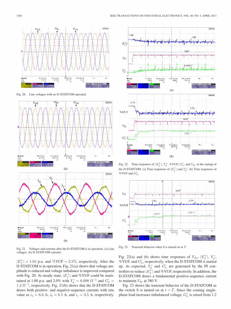
Fig. 20 shows bus voltage v before the D-STATCOMis started. Line voltages vab, vbc, and vca fluctuate with
1426 IEEE TRANSACTIONS ON INDUSTRIAL ELECTRONICS, VOL. 60, NO. 4, APRIL 2013
Fig. 20. Line voltages with no D-STATCOM operated.
Fig. 21. Voltages and currents after the D-STATCOM is in operation. (a) Linevoltages. (b) D-STATCOM currents.
|E+f | = 1.04 p.u. and %VUF = 2.5%, respectively. After the
D-STATCOM is in operation, Fig. 21(a) shows that voltage am-plitude is reduced and voltage imbalance is improved comparedwith Fig. 20. At steady state, |E+
f | and %VUF could be main-tained at 1.00 p.u. and 2.0% with Y ∗
p = 0.098 Ω−1 and G∗n =
1.2 Ω−1, respectively. Fig. 21(b) shows that the D-STATCOMdraws both positive- and negative-sequence currents with rmsvalue as ia = 6.6 A, ib = 8.5 A, and ic = 3.5 A, respectively.
Fig. 22. Time responses of |E+f|, Y ∗
p , %VUF, G∗n, and Vdc in the startup of
the D-STATCOM. (a) Time responses of |E+f| and Y ∗
p . (b) Time responses of%VUF and G∗
n.
Fig. 23. Transient behavior when S is turned on at T .
Fig. 22(a) and (b) shows time responses of Vdc, |E+f |, Y ∗
p ,%VUF, and G∗
n, respectively, when the D-STATCOM is startedup. As expected, Y ∗
p and G∗n are generated by the PI con-
trollers to reduce |E+f | and %VUF, respectively. In addition, the
D-STATCOM draws a fundamental positive-sequence currentto maintain Vdc at 380 V.
Fig. 23 shows the transient behavior of the D-STATCOM asthe switch S is turned on at t = T . Since the coming single-phase load increases imbalanced voltage, G∗
n is raised from 1.2
LEE et al.: D-STATCOM WITH ADMITTANCE AND CONDUCTANCE TO MITIGATE VOLTAGE FLUCTUATIONS 1427
to 1.7 Ω−1 to maintain %VUF at 2%. The dc voltage Vdc alsoshows tight regulation at 380 V in the switching moment. Notethat |E+
f | and Y ∗p are almost not changed due to slight variation
of the load in this test.
VII. CONCLUSION
This paper has presented a control method of theD-STATCOM to alleviate voltage fluctuations in high-levelpenetration of DG systems. Together with positive-sequenceadmittance to recover the positive-sequence voltage, negative-sequence conductance is implemented to cooperatively improveimbalanced voltage. A tuning control is designed to dynami-cally adjust admittance as well as conductance commands tomaintain both positive- and negative-sequence voltages at anallowable level in response to power variation of DGs or loads.
Extended discussions on the relationship between theD-STATCOM current and its voltage regulation have beenpresented. The D-STATCOM is controlled by separately ad-justing admittance and conductance, and the compromise be-tween the D-STATCOM rating and the required improvementon power quality can be accomplished. The voltage-regulationperformances of the D-STATCOM deployed at different loca-tions have also been investigated. The termination–installationD-STATCOM is the best option to suppress voltage fluctu-ations. However, practical installation of the D-STATCOMmight be dependent on the DG location and the loading profile,as well as on the feeder configuration. For example, largeclusters of current-controlled DGs are usually connected at theend of the lateral in the distributed power system. The proposedD-STATCOM can be installed at the same location to mitigatevoltage fluctuations, so more DGs can be allowed online.
Finally, the cooperative control of the D-STATCOM has beendiscussed. By establishing a low-frequency communication, theD-STATCOM can work together with both OLTC and SVCto regulate the grid voltage. Thus, the rated kilovolt–amperecapacity of the D-STATCOM can be significantly reduced.In addition, multiple D-STATCOMs are able to cooperativelyprovide reactive-power compensation under the help of the so-called droop control. Various D-STATCOMs can evenly shareworkload according to their kilovolt–ampere rating.
REFERENCES
[1] R. Lasseter, “Microgrids,” in Proc. IEEE Power Eng. Soc. Winter Meeting,2002, pp. 305–308.
[2] F. Katiraei, R. Iravani, N. Hatziargyriou, and A. Dimeas, “Microgridsmanagement,” IEEE Power Energy Mag., vol. 6, no. 3, pp. 54–65,May/Jun. 2008.
[3] Consortium for Electric Reliability Technology Solutions (CERTS),US2010. [Online]. Available: http://certs.lbl.gov/
[4] Department of the New Energy and Industrial Technology De-velopment Organization (NEDO), Japan, 2010. [Online]. Available:http://www.nedo.go.jp/english/index.html
[5] C. L. Masters, “Voltage rise: The big issue when connecting embeddedgeneration to long 11 kV overhead lines,” Inst. Elect. Eng. Power Eng. J.,vol. 16, no. 1, pp. 5–12, Feb. 2002.
[6] IEEE Standard for Interconnecting Distributed Resources With ElectricPower Systems, IEEE Std. 1547.2-2008, 2008.
[7] A. V. Jouanne and B. Banerjee, “Assessment of voltage unbalance,” IEEETrans. Power Del., vol. 16, no. 4, pp. 782–790, Oct. 2001.
[8] T. Senjyu, Y. Miyazato, A. Yona, N. Urasaki, and T. Funabashi, “Optimaldistribution voltage control and coordination with distributed generation,”IEEE Trans. Power Del., vol. 23, no. 2, pp. 1236–1242, Apr. 2008.
[9] D. Westermann and M. Kratz, “A real-time development platform for thenext generation of power system control functions,” IEEE Trans. Ind.Electron., vol. 57, no. 4, pp. 1159–1166, Apr. 2010.
[10] L. Gyugyi, “A unified power flow control concept for flexible ac trans-mission systems,” Proc. Inst. Elect. Eng., vol. 139, no. 4, pp. 323–331,Jul. 1992.
[11] C. Schauder, M. Gernhardt, E. Stacey, T. Lemak, L. Gyugyi, T. Cease,and A. Edris, “Development of a ±100 MVAr static condenser for voltagecontrol of transmission systems,” IEEE Trans. Power Del., vol. 10, no. 3,pp. 1486–1496, Aug. 1995.
[12] N. G. Hingorani and L. Gyugyi, Understanding FACTS: Concepts andTechnology of Flexible AC Transmission Systems. New York: Wiley,1999.
[13] H. Akagi, “Active harmonic filters,” Proc. IEEE, vol. 93, no. 12, pp. 2128–2141, Dec. 2005.
[14] R. Gupta, A. Ghosh, and A. Joshi, “Multiband hysteresis modulation andswitching characterization for sliding-mode-controlled cascaded multi-level inverter,” IEEE Trans. Ind. Electron., vol. 57, no. 7, pp. 2344–2353,Jul. 2010.
[15] P. S. Sensarma, K. R. Padiyar, and V. Ramanarayanan, “Analysis andperformance evaluation of a distribution STATCOM for compensatingvoltage fluctuations,” IEEE Trans. Power Del., vol. 16, no. 2, pp. 259–264, Apr. 2001.
[16] E. Twining, M. J. Newman, P. C. Loh, and D. G. Holmes, “Voltagecompensation in weak distribution networks using a D-STATCOM,” inProc. IEEE PEDS, 2003, pp. 178–183.
[17] H. Fujita and H. Akagi, “Voltage-regulation performance of a shunt activefilter intended for installation on a power distribution system,” IEEETrans. Power Electron., vol. 22, no. 3, pp. 1046–1053, May 2007.
[18] T.-L. Lee and P.-T. Cheng, “Design of a new cooperative harmonic filter-ing strategy for distributed generation interface converters in an islandingnetwork,” IEEE Trans. Power Electron., vol. 42, no. 5, pp. 1301–1309,Sep. 2007.
[19] Y.-R. Mohamed and E. El-Saadany, “A control scheme for PWM voltage-source distributed-generation inverters for fast load-voltage regulation andeffective mitigation of unbalanced voltage disturbances,” IEEE Trans. Ind.Electron., vol. 55, no. 5, pp. 2072–2084, May 2008.
[20] P. Carvalho, P. Correia, and L. Ferreira, “Distributed reactive power gen-eration control for voltage rise mitigation in distribution networks,” IEEETrans. Power Syst., vol. 23, no. 2, pp. 766–772, May 2008.
[21] P.-T. Cheng, C.-A. Chen, T.-L. Lee, and S.-Y. Kuo, “A cooperative imbal-ance compensation method for distributed-generation interface convert-ers,” IEEE Trans. Ind. Appl., vol. 45, no. 2, pp. 805–815, Mar./Apr. 2009.
[22] D. De and V. Ramanarayanan, “Decentralized parallel operation of in-verters sharing unbalanced and nonlinear loads,” IEEE Trans. PowerElectron., vol. 25, no. 12, pp. 3015–3025, Dec. 2010.
[23] C. Tufon, A. Isemonger, B. Kirby, J. Kueck, and F. Li, “A tariff for reactivepower,” in Proc. IEEE PSCE, 2009, pp. 1–7.
[24] B. Kroposki, C. Pink, R. DeBlasio, H. Thomas, M. Simoes, and P. Sen,“Benefits of power electronic interfaces for distributed energy systems,”IEEE Trans. Energy Convers., vol. 25, no. 3, pp. 901–908, Sep. 2010.
[25] J. M. Guerrero, J. C. Vasquez, J. Matas, L. G. de Vicuna, and M. Castilla,“Hierarchical control of droop-controlled ac and dc microgrids—Ageneral approach toward standardization,” IEEE Trans. Ind. Electron.,vol. 58, no. 1, pp. 158–172, Jan. 2011.
[26] T.-L. Lee, S.-H. Hu, and Y.-H. Chan, “Design of D-STATCOM for voltageregulation in microgrids,” in Proc. IEEE Energy Convers. Congr. Expo.,2010, pp. 3456–3463.
[27] D. N. Zmood and D. G. Holmes, “Stationary frame current regulationof PWM inverters with zero steady-state error,” IEEE Trans. PowerElectron., vol. 18, no. 3, pp. 814–822, May 2003.
[28] F. Blaabjerg, R. Teodorescu, M. Liserre, and A. V. Timbus, “Overviewof control and grid synchronization for distributed power generationsystems,” IEEE Trans. Ind. Electron., vol. 53, no. 5, pp. 1398–1409,Oct. 2006.
[29] E. Demirok, D. Sera, R. Teodorescu, P. Rodriguez, and U. Borup, “Eval-uation of the voltage support strategies for the low voltage grid connectedPV generators,” in Proc. IEEE Energy Convers. Congr. Expo., 2010,pp. 710–717.
[30] G. Azevedo, P. Rodriguez, J. Rocabert, M. Cavalcanti, and F. Neves,“Voltage quality improvement of microgrids under islanding mode,” inProc. IEEE Energy Convers. Congr. Expo., 2010, pp. 3169–3173.
[31] Website of Texas Instruments, 2010. [Online]. Available: http://www.ti.com/

1428 IEEE TRANSACTIONS ON INDUSTRIAL ELECTRONICS, VOL. 60, NO. 4, APRIL 2013
Tzung-Lin Lee (S’04–M’08) received the B.S. de-gree in electrical engineering from Chung YuanChristian University, Taoyuan, Taiwan, in 1993, theM.S. degree in electrical engineering from NationalChung Cheng University, Chiayi, Taiwan, in 1995,and the Ph.D. degree in electrical engineering fromNational Tsing Hua University, Hsinchu, Taiwan,in 2007.
From 1997 to 2001, he was with the MicrowaveDepartment, Electronics Research and Service Or-ganization, Industrial Technology Research Institute,
Hsinchu. He began his teaching career in Chang Gung University, Taoyuan,in September 2007. Since August 2008, he has been with the Department ofElectrical Engineering, National Sun Yat-Sen University, Kaohsiung, Taiwan,where he is currently an Assistant Professor. His research interests are in utilityapplications of power electronics, such as active power filters and microgrids.
Shang-Hung Hu (S’10) received the B.S. degreein electrical engineering from the National TaiwanUniversity of Science and Technology, Taipei, Tai-wan, in 2008 and the M.S. degree in electricalengineering from National Sun Yat-Sen University,Kaohsiung, Taiwan, in 2010, where he is currentlyworking toward the Ph.D. degree in the Departmentof Electrical Engineering.
His recent research includes active power filtersand inverter controls in microgrids.
Yu-Hung Chan received the B.S. degree in electricalengineering from Feng Chia University, Taichung,Taiwan, in 2009 and the M.S. degree in electricalengineering from National Sun Yat-Sen University,Kaohsiung, Taiwan, in 2011.
He is currently with the Department of Elec-trical Engineering, National Sun Yat-Sen Univer-sity, Kaohsiung. His research interests include activepower filters and inverter controls.