d-series™ lcd control panels - imagine … or any part thereof, in any form, by any method, for...
TRANSCRIPT
Reference
D-Series™ LCD Control Panels 9-April-2014
For Panels: Single Automation Bus Panel (ACP-1)
CPU Change Over Panel (CPU-1)
16-Button LCD Control Panel (CP-LCD-16)
Revision: Release

D-Series™ LCD Control Panels Reference
Publication Information © 2014 Imagine Communications Corp. Proprietary and Confidential.
Imagine Communications considers this document and its contents to be proprietary and confidential. Except for making a reasonable number of copies for your own internal use, you may not reproduce this publication, or any part thereof, in any form, by any method, for any purpose, or in any language other than English without the written consent of Imagine Communications. All others uses are illegal.
This publication is designed to assist in the use of the product as it exists on the date of publication of this manual, and may not reflect the product at the current time or an unknown time in the future. This publication does not in any way warrant description accuracy or guarantee the use for the product to which it refers. Imagine Communications reserves the right, without notice to make such changes in equipment, design, specifications, components, or documentation as progress may warrant to improve the performance of the product.
Trademarks Product names and other brands (such as ADC™, D-Series™, Nexio®, Nexio® Insight, Nexio® Motion, PowerSmart®, Versio™) are trademarks or trade names of Imagine Communications or its subsidiaries. Microsoft® and Windows® are registered trademarks of Microsoft Corporation. All other trademarks and trade names are the property of their respective companies.
Contact Information Imagine Communications has office locations around the world. For domestic and international location and contact information see: http://www.imaginecommunications.com/contact-us/
Support Contact Information For domestic and international support contact information see:
Support Contacts: http://www.imaginecommunications.com/services/technical-support/
eCustomer Portal: http://support.imaginecommunications.com
© 2014 Imagine Communications Corp. Proprietary and Confidential 9-April-2014 | Page 2 of 41

D-Series™ LCD Control Panels
Reference Contents
Contents
About this Manual ................................................................................................. 6
Audience ................................................................................................................................................... 6
Measurement Standards .......................................................................................................................... 6
Product Unpacking Notes ......................................................................................................................... 6
WEEE and RoHS Compliance .................................................................................................................... 6
Single Bus Automation Control Panel (ACP-1) ........................................................ 8
About the panel ........................................................................................................................................ 8
Specifications ....................................................................................................................................... 9
The Single Bus Control Front Panel .......................................................................................................... 9
Control Buttons .................................................................................................................................. 10
Front Panel LED Display ...................................................................................................................... 12
Communication Troubleshooting ...................................................................................................... 13
Change Over Control Panel (CPU-1) ..................................................................... 14
About the panel ...................................................................................................................................... 14
Specifications ..................................................................................................................................... 15
The CPU-1 Changeover Front Panel ....................................................................................................... 15
LCD Buttons ........................................................................................................................................ 16
Status LEDs ......................................................................................................................................... 17
Communication Troubleshooting ...................................................................................................... 17
16-Button LCD Control Panel (CP-LCD16) ............................................................. 18
About the panel ...................................................................................................................................... 18
Specifications ..................................................................................................................................... 18
The CP-LCD Front Panel .......................................................................................................................... 19
LCD Selector Buttons .......................................................................................................................... 20
© 2014 Imagine Communications Corp. Proprietary and Confidential 9-April-2014 | Page 3 of 41

D-Series™ LCD Control Panels
Reference Contents
Communication Troubleshooting ...................................................................................................... 20
The Back Panel ..................................................................................................... 21
Common Back Panel Layout ................................................................................................................... 21
Connectors/Ports/Dipswitches/LEDs ................................................................................................. 21
Diagnostics .............................................................................................................................................. 23
LCD Displays ....................................................................................................................................... 23
Rear Panel LEDs .................................................................................................................................. 23
Diagnostic Console Serial Port ........................................................................................................... 23
Panel Setup .......................................................................................................... 25
Factory Presets ....................................................................................................................................... 25
Panel Type Settings ............................................................................................................................ 25
Default Communications Port Settings .............................................................................................. 25
Link Postions ....................................................................................................................................... 25
Default SW3 DIP Switch Settings ........................................................................................................ 26
Required Connections ............................................................................................................................ 26
CPU ChangeOver Panel ...................................................................................................................... 27
16 button DAP and the Single Bus Control Panel ............................................................................... 27
Making Connection ................................................................................................................................. 27
Power Connection .............................................................................................................................. 27
GPI Connections ................................................................................................................................. 27
Ethernet Port ...................................................................................................................................... 28
RS-422 Serial Ports A and B ................................................................................................................ 28
Diagnostics Port .................................................................................................................................. 29
RS-232 Serial Port ............................................................................................................................... 29
USB Ports A and B ............................................................................................................................... 30
Cabling .................................................................................................................................................... 30
Unit Replacement ................................................................................................ 31
Notice to the Original Purchaser ............................................................................................................ 31
To Return a Unit ..................................................................................................................................... 31
To Order a New or Replacement Unit .................................................................................................... 32
© 2014 Imagine Communications Corp. Proprietary and Confidential 9-April-2014 | Page 4 of 41

D-Series™ LCD Control Panels
Reference Contents
Reference: Upgrading Firmware .......................................................................... 33
About Upgrading Panel Firmware .......................................................................................................... 33
Upgrading Firmware via Serial Connection ........................................................................................ 33
Upgrading Firmware via TCP/IP Connection ...................................................................................... 34
Network Related U-Boot Environment Variables ................................................................................... 35
To Change Environment Settings ....................................................................................................... 35
About Rear Panel DIP Switch SW3 Settings ....................................................................................... 36
To Run the New Firmware ...................................................................................................................... 38
Reference: Jumpers ............................................................................................. 39
Internal Jumper Settings ......................................................................................................................... 39
JP5 Active Serial Ports ........................................................................................................................ 39
J7 Control Panel Configuration........................................................................................................... 39
Rarely Used Jumpers .......................................................................................................................... 40
© 2014 Imagine Communications Corp. Proprietary and Confidential 9-April-2014 | Page 5 of 41

D-Series™ LCD Control Panels
Reference About this Manual
About this Manual
Audience This manual is intended as a general reference and for use by engineers or technicians when installing professional automation computers.
Measurement Standards The following measurement standards are used in this manual:
Rack Unit (RU) is an Imperial standard measurement for device height. (While also seen as U.) [1RU = 44.45mm = 1.75 inches]
19” Rack Standard is an international standard for racking width. [19” Rackmount standard = 482.6mm]
Other measures for in-document conversion: (1m = 3.281ft), (0.3048m = 1ft), (25.4mm = 1in), (1kg = 2.205lb)
Website for length & weight conversions: http://www.convert-me.com/en/convert
Product Unpacking Notes Thoroughly inspect all articles immediately upon receipt. Any damage discovered should be cause for a damage claim against the carrier.
WEEE and RoHS Compliance Panels addressed in this document are WEEE and RoHS Compliant. This includes compliance with Electrical and Electronic Equipment (WEEE) and Restriction on Hazardous Substances (RoHS) (Combined WEEE/RoHS) requirements now mandated in Europe, and being adopted in other parts of the world.
• Restriction of Hazardous Substances Directive (RoHS) 2002/95/EC mandates: Recycling of devices at end of life and the elimination or reduction of a list of hazardous substances. This includes six key hazardous materials typically used in the manufacture of various types of electronic and electrical equipment: Lead, Mercury, Cadmium,
© 2014 Imagine Communications Corp. Proprietary and Confidential 9-April-2014 | Page 6 of 41

D-Series™ LCD Control Panels
Reference About this Manual
Hexavalent chromium (chromium VI or Cr6+), Polybrominated biphenyls (PBB), and Polybrominated diphenyl ether (PBDE)
• Waste Electrical and Electronic Equipment Directive (WEEE Directive) 2002/96/EC sets collection, recycling and recovery targets for all types of electrical goods. The directive imposes the responsibility for the disposal of waste electrical and electronic equipment (WEEE) on the manufacturers of such equipment. The companies are compelled to use the collected waste in an ecological-friendly manner, either by ecological disposal or by reuse/refurbishment of the collected WEEE. Under WEEE "Users of electrical and electronic equipment from private households should have the possibility of returning WEEE at least free of charge"
© 2014 Imagine Communications Corp. Proprietary and Confidential 9-April-2014 | Page 7 of 41

D-Series™ LCD Control Panels
Reference Single Bus Automation Control Panel (ACP-1)
Single Bus Automation Control Panel (ACP-1)
About the panel A Single Bus Automation Control Panel (ACP-1) is a 1 RU panel with 11 LCD buttons and 8 front panel status LEDs that provides the primary user interface for manual control of a single automated transmission channel. It is designed for stations that need or want the capability of single channel intervention from a dedicated control panel.
Configurable backlit LCD buttons are used to display the channel applications
Buttons and schedule warning lights provide additional control and status information for the assigned channel
When an automation workstation switches between channels, the panel control functions follow the channel being viewed
Features The Single Bus Automation Control Panel enables greater operational freedom through the following features:
Automatically presents status information on the currently assigned channel
Reduces space required for equipment, particularly when the operator is dedicated to single-channel control
Provides direct control of manual channel execution, such as Take and Hold, as well as inserting captions, running logos, voice-overs, etc.
Allows direct intervention for failure recovery
Offers fast, unambiguous button access over the conventional keyboard and mouse
Provides immediate feedback to the operator’s actions
Functions The Single Bus Automation Control Panel provides an operator with the following functions:
Transmission control button standard functions include: Take, Hold, Cue, Pretake, Skip, and Default for the main event.
© 2014 Imagine Communications Corp. Proprietary and Confidential 9-April-2014 | Page 8 of 41

D-Series™ LCD Control Panels
Reference Single Bus Automation Control Panel (ACP-1)
Schedule error lights provide warnings of several error states that may be present in a channel and are an excellent status overview – schedule/time, source conflict, item not available, source not available, data error, back-up error, source error, hold/manual.
Five station-defined button functions depend on system-specific configuration and allow for operations such as inserting captions, running logos and voice-overs.
Specifications The following table provides a brief list of specifications for a Single Bus Automation Control Panel (ACP-1).
Specification Description
Size Height: 1RU Width: 19” Rackmount standard Depth: 140mm
Weight 1.23kg
Power Requirements 12v DC Power supply: 12v power brick ( www.xppower.com model AEL 15US12 )
The Power supply has a 1.3M cable with 2.1mm jack that plugs directly into the panel. The Power Brick has an IEC power connector.
A 5-pin Phoenix power connector is provided for connecting – if required - to an old style dual redundant PSU125.
Current Quiescent current is in the region of 350ma
Cabling A null modem cable is provided for direct connection to a PC RS232 COM port, but USB cables can also be used. RS 422 connections are available via RJ45 sockets for connecting CPU-1 changeover panels to automation computers.
Typical Location Transmission control area connected to the workstation computers.
Mounting Requirements Standard 19” rackmount and no special mounting requirements.
The Single Bus Control Front Panel The Single Bus Automation Control Panel is used to select, control, and display the status for a single bus/channel. Groups of pushbuttons and indicators form the operator interface.
The front panel of a Single Bus Control Panel is comprised of two functional sections:
© 2014 Imagine Communications Corp. Proprietary and Confidential 9-April-2014 | Page 9 of 41
D-Series™ LCD Control Panels
Reference Single Bus Automation Control Panel (ACP-1)
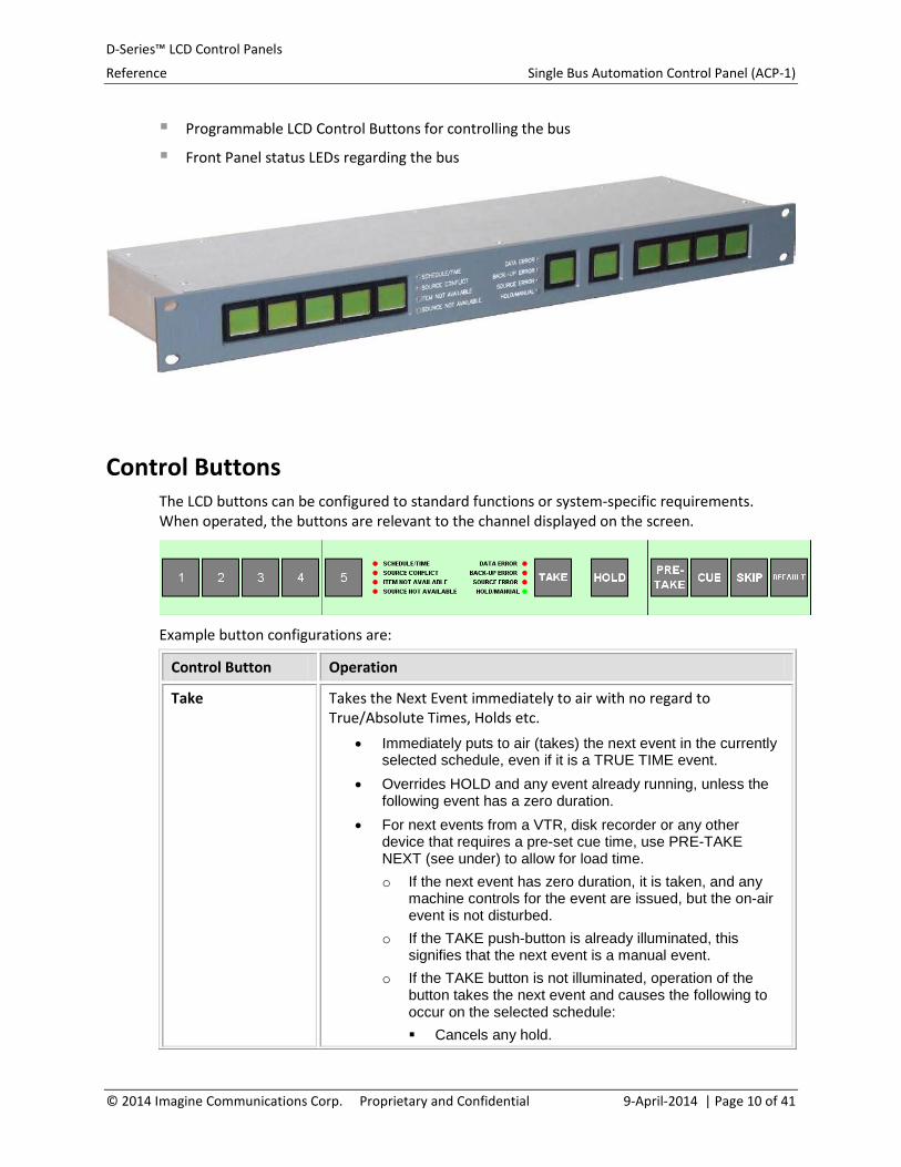
Programmable LCD Control Buttons for controlling the bus
Front Panel status LEDs regarding the bus
Control Buttons The LCD buttons can be configured to standard functions or system-specific requirements. When operated, the buttons are relevant to the channel displayed on the screen.
Example button configurations are:
Control Button Operation
Take Takes the Next Event immediately to air with no regard to True/Absolute Times, Holds etc.
• Immediately puts to air (takes) the next event in the currently selected schedule, even if it is a TRUE TIME event.
• Overrides HOLD and any event already running, unless the following event has a zero duration.
• For next events from a VTR, disk recorder or any other device that requires a pre-set cue time, use PRE-TAKE NEXT (see under) to allow for load time. o If the next event has zero duration, it is taken, and any
machine controls for the event are issued, but the on-air event is not disturbed.
o If the TAKE push-button is already illuminated, this signifies that the next event is a manual event.
o If the TAKE button is not illuminated, operation of the button takes the next event and causes the following to occur on the selected schedule: Cancels any hold.
© 2014 Imagine Communications Corp. Proprietary and Confidential 9-April-2014 | Page 10 of 41

D-Series™ LCD Control Panels
Reference Single Bus Automation Control Panel (ACP-1)
Control Button Operation
Terminates the on-air event, unless the next event has zero duration.
The current event’s countdown timer changes to the Pretake time (e.g. 10 seconds) and counts down.
If the next switching event in the schedule is a true-time event, it is taken.
If the schedule is empty, the default event for the schedule is taken.
Hold Stops the duration countdown and the Next Event is not taken to air. • Holds the on-air duration and does not count down,
preventing the next item in the schedule from being broadcast i.e. it holds the selected schedule. Maintains the current source until the button is released, or a TAKE occurs to re-start the schedule.
• Toggles on and off, with light displayed when a selected bus is in the HOLD condition. An example of use would be to HOLD a logo on-screen if the next on-air event was not ready.
PreTake Cues the next item and Takes it in a preset countdown time. The time is configured to allow the slowest device in your system time enough to cue correctly.
• If the PRETAKE NEXT button is not illuminated, operation of the button takes the next event and causes the following to occur on the selected schedule. o Cancels any hold. o Terminates the on-air event, unless the next event has a
zero duration. o Takes the next switching event in the schedule, even if it
is a true-time event. o If the schedule is empty, the default event for the
schedule is taken. • If the next event has zero duration, it is taken, and any
machine controls for the event are issued, but the on-air event is not disturbed.
• If the PRETAKE NEXT push-button is illuminated, this signifies that the next event is a manual event.
Cue Forces the item in the Next Event line to cue.
Skip Causes the next Commercial Break to be skipped. The break is not transmitted; it is just placed in the As-Run Log with the time that the Skip command was issued.
Default Puts the Default Event to air and stops the Schedule.
‘Blank’ buttons (1- The operations of these blank buttons are station-defined.
© 2014 Imagine Communications Corp. Proprietary and Confidential 9-April-2014 | Page 11 of 41

D-Series™ LCD Control Panels
Reference Single Bus Automation Control Panel (ACP-1)
Control Button Operation
5)
Front Panel LED Display Provides warnings of several Error Flags that may be present on a bus/channel informing the operator exactly what needs correction. It provides an overview of the channel to identify status information such as:
Schedule errors in timing, source etc.
Warnings also appear in the event in the schedule and at the bottom of the screen in red.
Warnings Action
Schedule Time Indicates a schedule timing error in the current or an upcoming scheduled event. This is likely due to an overlap in the scheduled times for several upcoming events.
Select the bus for display to determine the cause of the problem.
Source Conflict Indicates one or more events coming up in the schedule have a source that is also scheduled at the same time on another bus. Select the schedule for display to determine the cause of the problem.
Item Not Available
Indicates an upcoming scheduled item/event is not currently available on the designated playback source for that event.
Select the bus for display to determine the cause of the problem.
Source Not Available
Indicates one or more events are coming up for the bus that has a source that is not available, either because the source is not ready or it has not been reloaded.
Select the bus for display to determine the cause of the problem.
Data Error Indicates one or more events coming up in the schedule contain a Data Error, a Schedule Error, or a Source Conflict Error.
Select the schedule for display to determine the cause of the problem. Operation Details
• To enable the alarming of default events, the DATA ERROR indicator is illuminated if the default event is taken, and the flag is set in the Schedule specification table.
• For presentation schedules, the DATA ERROR indicator is illuminated when the number of events remaining in the
© 2014 Imagine Communications Corp. Proprietary and Confidential 9-April-2014 | Page 12 of 41

D-Series™ LCD Control Panels
Reference Single Bus Automation Control Panel (ACP-1)
Warnings Action
schedule for the schedule is less than the minimum number allowed.
Backup Error Indicates the backup source assigned for the current or an upcoming event is unavailable.
Select the bus for display to determine the cause of the problem.
Source Error Indicates the playback source for the current or an upcoming event is not available. Select the bus for display to determine the cause of the problem.
Hold/Manual The HOLD indicator shows one of two possible conditions: • The schedule is in HOLD mode, i.e. a numeric on-air duration is
not counting down and the next true-time event will not be taken. • The on-air event for the schedule has ‘MAN’ in its Duration field,
i.e. the operator is expected to terminate it manually by using the TAKE push-button.
Operation Details • The HOLD push-button toggles the selected schedule between
hold and normal modes. This LED is illuminated if the selected schedule is in HOLD mode.
• If a schedule is in HOLD mode, the computer stops counting down a numeric duration and does not switch true-time events.
• The TAKE push-button cancels the hold mode.
Communication Troubleshooting If no host computer is actively communicating with the control panel controller, the panel enters an inactive state. The first LCD button displays a bitmap indicating that there are no communications against a red background, all other LCD buttons are dark, and the front panel LEDs are off.
© 2014 Imagine Communications Corp. Proprietary and Confidential 9-April-2014 | Page 13 of 41

D-Series™ LCD Control Panels
Reference Change Over Control Panel (CPU-1)
Change Over Control Panel (CPU-1)
About the panel D-Series automation is renowned for its reliability. One of the reasons we can make this claim is because of our system’s redundancy. Dual-redundant automation computers equal automatic, seamless, and transparent changeover of control from the on-air computer to the back-up computer.
Dual-redundancy allows:
Automatic Changeover. If the backup computer detects a problem with the active computer, the backup/standby computer automatically takes control without affecting the running schedules.
Manual Changeover. This enables system maintenance or software updates to occur without impact to ongoing operations.
Main/Standby Computers: Dual redundant automation pairs consist of a Main and a Backup/Standby computer. If the Main computer fails, the Standby changes state to become the Main computer.
Features The CPU Changeover Panel offers the following features:
In the event of a failure, the automation software automatically performs the changeover between the computers. The Changeover Panel indicates the system state (Automatic or Manual) and the status of the on-air computer via LEDs.
Simplifies computer maintenance and system upgrading while maintaining on-air capability. With the push of a button the panel can set for manual switchover to allow maintenance and upgrade work on one of the computers.
Designed specifically for the multi-channel playout environment.
Fast, unambiguous button access over the conventional keyboard and mouse.
Enables direct user access and provides immediate feedback to the operator’s actions.
Functions The CPU Changeover Panel provides an operator with the following functions:
ARM: This function is the electronic equivalent of the shroud over a hardware button to prevent accidental engagement. It must be selected first to ‘arm’ a button.
© 2014 Imagine Communications Corp. Proprietary and Confidential 9-April-2014 | Page 14 of 41

D-Series™ LCD Control Panels
Reference Change Over Control Panel (CPU-1)
CPU Switchover: This function provides system state and selection between Automatic / Manual switchover modes.
CPU Selection: This function allows the operator to manually select Main / Standby computers.
Status LEDs display the current status of both computers.
Specifications The following table provides a brief list of specifications for the CPU Changeover Panel (CPU-1).
Specification Description
Size Height: 1RU Width: 19” Rackmount standard Depth: 140mm
Weight 1.23kg
Power Requirements 12v DC
Power supply: 12v power brick ( www.xppower.com model AEL 15US12 )
The Power supply has a 1.3M cable with 2.1mm jack that plugs directly into the panel. The Power Brick has an IEC power connector. A 5 pin Phoenix power connector is provided for anyone wishing to connect to an old style dual redundant PSU125.
Current Quiescent current is in the region of 350ma
Cabling RS 422 connections are available via RJ45 sockets (new SMS type pinout) for connecting CPU-1 changeover panels to both automation computers.
Typical Location Equipment room near the automation servers.
Mounting Requirements Standard 19” rackmount and no special mounting requirements.
The CPU-1 Changeover Front Panel The CPU-1 Changeover panel comes standard with our dual-redundant computers. This 1 RU panel with 5 LCD buttons and 6 front panel status LEDs displays the system state and CPU status, and provides fast, easy control over which computer is on-air.
Dedicated panel buttons provide system state and selection of Automatic / Manual Failover modes and Main / Standby computers.
© 2014 Imagine Communications Corp. Proprietary and Confidential 9-April-2014 | Page 15 of 41

D-Series™ LCD Control Panels
Reference Change Over Control Panel (CPU-1)
Status LEDs to display the current status of both computers to enable informed decision-making.
LCD Buttons Front Panel LCD buttons allow an operator to perform, as required, CPU Switchover between Manual and Automation operations and select a computer as main or standby.
The ARM function (ARM LCD button) is the electronic equivalent of the shroud over a hardware button. It must be selected first to ‘arm’ a button.
Button presses are only reported if they occur during the live period after pressing the ARM button. (The ARM button switches from green to amber during the live period).
CPU Switchover functions (MAN / AUTO LCD buttons) provide system state and selection between Automatic / Manual switchover modes. • The lit button (MAN or AUTO) indicates the current system status (Manual or
Automatic).
• The operator can select between Automatic and Manual Failover by simple button presses. (The system should always be set to Automatic, unless there are maintenance or upgrade needs on the Automation pair.)
The system should always be set to Automatic, unless there are maintenance or upgrade needs on the Automation pair.)
The system should only be placed in Manual Changeover Mode when engineers are working on the system, such as when performing a live system upgrade or PC maintenance in order to prevent the occurrence of unwanted change-over switches.
CPU Selection functions (CPU 1 / CPU 2 LCD buttons) allow the operator to manually select Main / Standby computers. • The lit button indicates the computer (CPU 1 or CPU 2) currently designated as main.
© 2014 Imagine Communications Corp. Proprietary and Confidential 9-April-2014 | Page 16 of 41

D-Series™ LCD Control Panels
Reference Change Over Control Panel (CPU-1)
• Switching Main/Standby computers is normally performed (in conjunction with
switching to Manual Changeover) to allow for maintenance on one of the automation pair computers.
LCD Button Background Colors
Button When Turned ON When Turned OFF
ARM Amber Green
MAN Amber Green
AUTO Amber Green
CPU1 Amber Red (failed) or Green (standby)
CPU2 Amber Red (failed) or Green (standby)
Status LEDs Status LEDs display the current status of both computers.
CPU FAIL: A red light indicates automation computer failure.
CLOCK FAIL: The computer can run from an external clock (default setting) or an internal clock (backup). The LEDs indicate the status of the external clock and which clock is being used.
STANDBY: A green light indicates this computer is currently designated as the ‘standby’ computer.
Communication Troubleshooting The CPU-1 panel communicates with two host computers using the RS-422 connections on ports 1 and 2, and reports button presses to both serial ports.
If no host computer is actively communicating with the control panel controller, the panel enters an inactive state. The first LCD button displays a bitmap indicating that there are no communications against a red background, all other LCD buttons are dark, and the front panel LEDs are off.
© 2014 Imagine Communications Corp. Proprietary and Confidential 9-April-2014 | Page 17 of 41

D-Series™ LCD Control Panels
Reference 16-Button LCD Control Panel (CP-LCD16)
16-Button LCD Control Panel (CP-LCD16)
About the panel The 16-Button LCD Control Panel (CP-LCD16) is a 1 RU panel designed specifically to enhance the D-Series automation software controlling multiple-channel playout. With panels containing 16 buttons, the CP-LCD16 can be programmed to provide a range of functions. Most commonly used when breakdowns or other failures occur, each button on the 16-button LCD panel can call up actions needed in a hurry. For example, a button can cut back to Network or a backup cart machine with a ready spot reel (breaktape). Or a button can be configured to display a full-screen apology slide or trigger a caption for missing audio.
This panel can be used for a number of different functions (bus selection, bus bank selection, direct access, etc.) depending on how it is configured when connected to DALstation.
Features The CP-LCD16 Panel offers the following features:
• An array of configurable, backlit LCD buttons that call up actions depending upon the system’s configuration.
• Configurable emergency functionality for each specific working environment. • The 16-button configuration complements automation software functions. Typically, the
button colors are configured as: Green (Available), Amber (Active), and Red (Alarm Condition).
Functions The CP-LCD16 Panel provides an operator with the following functions:
• Panels can be used to select monitors or switch between Main and Reserve paths, etc. • Each button’s functionality, such as controlling captions, can be called up via a
DALstation workstation for review.
• For manual control of a master control switcher (vision mixer), an LCD button can be programmed to enter semi-automatic mode. This mode gives the operator automation-assisted, manual control.
Specifications The following table provides a brief list of specifications for the CP-LCD16 Panel.
© 2014 Imagine Communications Corp. Proprietary and Confidential 9-April-2014 | Page 18 of 41

D-Series™ LCD Control Panels
Reference 16-Button LCD Control Panel (CP-LCD16)
Specification Description
Size Height: 1RU Width: 19” Rackmount standard
Depth: 140mm
Weight 1.23kg
Power Requirements 12v DC
Power supply: 12v power brick ( www.xppower.com model AEL 15US12 )
The Power supply has a 1.3M cable with 2.1mm jack that plugs directly into the panel. The Power Brick has an IEC power connector. A 5 pin Phoenix power connector is provided for anyone wishing to connect to an old style dual redundant PSU125.
Current Quiescent current is in the region of 350ma
Cabling A null modem cable is provided for direct connection to a PC RS232 COM port, but USB cables can also be used. RS 422 connections are available via RJ45 sockets (new SMS type pinout) for connecting CPU-1 changeover panels to automation computers.
Typical Location Transmission control area connected to the workstation computers.
Mounting Requirements Standard 19” rackmount and no special mounting requirements.
The CP-LCD Front Panel The LCD Control Panel gives operators a choice in controlling automation environments by providing unambiguous button control in addition to conventional keyboard and mouse operations.
© 2014 Imagine Communications Corp. Proprietary and Confidential 9-April-2014 | Page 19 of 41

D-Series™ LCD Control Panels
Reference 16-Button LCD Control Panel (CP-LCD16)
CP-LCD-16 panel front
LCD Selector Buttons The programmable LCD buttons allow an operator to call up predefined actions depending upon the system’s configuration, such as controlling captions, selecting monitors, switching between Main and Reserve paths, or actioning defined emergency functionality.
Pressing an LCD pushbutton illuminates the pushbutton to indicate it is ‘selected.’
LCD Button Colors Bus Selector buttons are illuminated to show several states, such as:
Green: The button operation is unselected and available.
Amber: The button operation is selected.
Red: An alarm condition exists on the defined function.
Communication Troubleshooting If no host computer is actively communicating with the control panel controller, the panel enters an inactive state. The first LCD button displays a bitmap indicating that there are no communications against a red background, all other LCD buttons are dark, and the front panel LEDs are off.
© 2014 Imagine Communications Corp. Proprietary and Confidential 9-April-2014 | Page 20 of 41

D-Series™ LCD Control Panels
Reference The Back Panel
The Back Panel
Common Back Panel Layout New D-Series Control Panels share the same back panel configuration.
Connectors/Ports/Dipswitches/LEDs The back panel layout is listed below in order presented - from left to right - on the above graphic:
Power Connectors 5-pin Phoenix connector and an alternate 2.1mm concentric power connector. One of these must be connected to supply +12v DC.
General Purpose Inputs and Outputs Two 25-pin connectors provide 16 general purpose inputs and 16 general purpose outputs, respectively, that can be controlled by the software communicating with the control panel (e.g. DALstation).
Example Use: GPI triggers accepted from DALstation based on looking at the event audio information can drive an external audio monitor that switches for MONO, STEREO, AC3 based on the GPIs.
Note: GPIO functionality is only available on the ACP-1 Single bus panel and the CP-LCD16 16 Button panel.
Ethernet Port An RJ-45 connector provides a standard 10/100 Mbs Ethernet connection.
Note: With the initial release of these panels, the only supported use for the network connection is for downloading new firmware via the boot loader.
© 2014 Imagine Communications Corp. Proprietary and Confidential 9-April-2014 | Page 21 of 41

D-Series™ LCD Control Panels
Reference The Back Panel
RS-422 Serial Ports A and B Two RJ-45 connectors (labeled RS-422-A and RS-422-B) provide RS-422 serial connections for communications between the control panel and a controller application (such as DALstation). The baud rate for these ports is determined by the DIP switch settings selected on the Rear Panel DIP Switch SW3.
Diagnostics Port An RS-232 serial connection via the rear mounted DB-9M connector is used for diagnostics and software download.
The baud rate for this serial port is fixed at 57600 baud, 8 data bits, no parity, and one stop bit. It is used during software development, for downloading new firmware, and may be useful for diagnosing some software problems.
Low level communication problems generate diagnostic messages on the diagnostic serial port. Although the diagnostic port is unlikely to be connected during normal operation, these messages provide more detailed information than is possible using the rear panel LEDs.
RS-232 Serial Port An RS-232 serial connection via the rear mounted DB-9M connector is used for communications between the control panel and a controller application (such as DAL-station). The baud rate for this port is determined by the DIP switch settings selected on the Rear Panel DIP Switch SW3.
Note: Depending on the setting of jumper JP5, either the RS-232 serial port or the USB port B (USB to serial converter) will be active, but never both.
USB Ports A and B Two USB type ports A and B provide a connection to internal USB to serial port converters. These are used to provide a virtual serial connection between the control panel and a controller application (such as DALstation) when no serial port is available on the PC.
Note: Depending on the setting of jumper JP5, either the RS-232 serial port or the USB port B (USB to serial converter) will be active, but never both.
DIP Switch SW3 Rear Panel DIP Switch SW3 configures control panel behavior. These dipswitches normally come preset by the factory, but can be used to configure frequently changed options.
Diagnostic LEDs Eight (8) diagnostic LEDs on the rear panel provide feedback on the state of communications with the controller(s) and confirmation of panel power usage. They are used to help diagnose communication problems. (See Diagnostics below.)
© 2014 Imagine Communications Corp. Proprietary and Confidential 9-April-2014 | Page 22 of 41

D-Series™ LCD Control Panels
Reference The Back Panel
Diagnostics Diagnostics are available to monitor panel start-up, pane communications and control panel firmware operations. The control panel application provides diagnostic information via several channels: the LCD buttons, the rear panel LEDs, and the diagnostic serial port.
LCD Displays When the control panel is first started, it takes about 12 seconds to boot. Once the control panel application starts, the leftmost LCD button display shows the text “’xxx’ Panel” against a bright green background.
Whenever the control panel has not received a message from a controller application (such as DALstation) for more than 5 seconds, the leftmost LCD button displays “No Comm” against a bright red background (this text is overlaid by a circle with a diagonal bar flashing once a second).
Rear Panel LEDs Eight (8) diagnostic LEDs on the rear panel provide feedback on the state of communications with the controller(s) and confirmation of panel power usage.
The first four LEDs are used to show activity on the serial ports the control panel uses to communicate with a controller. Each time the control panel processes a message from the controller (i.e. a valid LCD Protocol command is received on a serial port), the corresponding LED flashes.
The fifth LED is reserved for indicating a valid LCD Protocol command is received via a TCP connection.
LED number Meaning
1 Receive activity on RS-422-A
2 Receive activity on RS-422-B
3 Receive activity on RS-232 or USB-B
4 Receive activity on USB-A
# The remaining diagnostic LEDs do not have a function assigned.
Diagnostic Console Serial Port The RS-232 diagnostics serial port provides information from all components of the control panel firmware:
1. At boot time, it displays diagnostics from the boot loader. It can also be used to issue interactive commands to the boot loader console when the rear panel DIP switch is set so the boot loader remains in interactive console mode.
© 2014 Imagine Communications Corp. Proprietary and Confidential 9-April-2014 | Page 23 of 41

D-Series™ LCD Control Panels
Reference The Back Panel
2. While the operating system boots, it displays console messages from the embedded
operating system uClinux.
3. Once the control panel application starts, it displays the application version and configuration information. During operation, the details of any communication errors that occur between the control panel and a controlling application (such as DALstation), are displayed on the diagnostic port.
Note: Normal communications do not generate any diagnostic output.
© 2014 Imagine Communications Corp. Proprietary and Confidential 9-April-2014 | Page 24 of 41

D-Series™ LCD Control Panels
Reference Panel Setup
Panel Setup
Factory Presets The control panels are configured at the factory for immediate use and changes will only be necessary if the customer requires settings other than the default (e.g. running the RS422 ports without terminations).
Panel Type Settings The type of panel is set by links on the 8x2 row jumper header J7 as follows:-
LCD-16 - no links fitted
ACP-1 - link fitted to 1st position only
CPU-1 - link fitted to 2nd position only
Default Communications Port Settings The default communications ports for each panel type is as follows:-
LCD-16 - RS232 or USB
ACP-1 - RS232 or USB
CPU-1 - dual RS422 ports
Link Postions All the links available on the Control Panel are shown in the following figure:
© 2014 Imagine Communications Corp. Proprietary and Confidential 9-April-2014 | Page 25 of 41

D-Series™ LCD Control Panels
Reference Panel Setup
Default SW3 DIP Switch Settings The default settings for the rear mounted DIP switch pack SW3 are shown below. SW3/7 & 8 should be UP (ON or CLOSED) for the panel software to run normally. These 2 switch sections are only ever set differently when new software is to be downloaded.
Baud Rate Settings To change the baud rate of the communications port then change SW3/5 & 6 as per the table below, but the default at 36,400 is with these 2 DOWN ( OFF or OPEN ).
SW3-5 SW3-6 Baud Rate
Open Open 38400 (only baud rate supported by DALstation)
Closed Open 9600
Open Closed 19200
Closed Closed 115200
Required Connections This section addresses the differences encountered when connecting control panels.
© 2014 Imagine Communications Corp. Proprietary and Confidential 9-April-2014 | Page 26 of 41

D-Series™ LCD Control Panels
Reference Panel Setup
CPU ChangeOver Panel Connect the CPU C/O panel to serial ports on both automation computers using the 2x RJ45 sockets which are the RS422 connections.
16 button DAP and the Single Bus Control Panel The 16 button DAP, and the Single Bus Control Panel both connect to a workstation using either:
The supplied NULL modem cable connected to the RS232 port on the control panel and to the DALstation’s COM1 RS232 port
OR
The USB socket on the control panel and a USB port on the DALstation
Making Connection The RS-232 serial port and built-in USB to serial port adapters mean that workstation computers won’t need an RS-422 capable serial card (or protocol adapter) to communicate with a CPC6800-based control panel.
Power Connection All panels provide a 2.1mm concentric power connector and (alternate) a Phoenix 5-pin type Power connector. One of these must be connected to supply +12v DC.
All panels provide a 12v power brick ( www.xppower.com model AEL 15US12 ) and a 1.3M cable with 2.1mm power jack that plugs directly into the panel. The power brick has an IEC power connector.
The (alternate) Phoenix 5-pin type connector has the same shell and cover as a standard 15-way D-type, but is specifically intended for power use (each pin is rated at 8A). This connector is provided for anyone wishing to connect to an old style dual redundant PSU125.
GPI Connections Two rear mounted DB-25 connectors provide 16 general purpose inputs and 16 general purpose outputs that can be controlled by the software communicating with the control panel (e.g. DALstation).
Example Use: GPI triggers accepted from DALstation based on looking at the event audio information can drive an external audio monitor that switches for MONO, STEREO, AC3 based on the GPIs.
© 2014 Imagine Communications Corp. Proprietary and Confidential 9-April-2014 | Page 27 of 41

D-Series™ LCD Control Panels
Reference Panel Setup
General Purpose Outputs A 25-pin female connector provides 16 general purpose outputs that can be controlled by the software communicating with the control panel.
Outputs 1-8 are connected to pins 1-8
Outputs 9-16 are connected to pins 18-25
All other pins are connected to ground.
General Purpose Inputs A 25-pin male connector provides 16 general purpose inputs whose states are reported to the software communicating with the control panel.
Inputs 1-8 are connected to pins 1-8,
Inputs 9-16 are connected to pins 18-25
All other pins are connected to ground.
Ethernet Port An RJ-45 connector provides a standard 10/100 Mbs Ethernet connection.
Note: As of version 1.0, the only supported use for the network connection is for downloading new firmware via the boot loader.
RS-422 Serial Ports A and B A dual RJ-45 connector provides two RS-422 serial connections for communications between the control panel and a controller application (such as DALstation). The baud rate for these ports is determined by the DIP switch settings selected on the Rear Panel DIP Switch SW3. For details see SW3- 5 and SW3-6: Serial Port Baud Rate.
The following UARTs are available for communications with external devices:
Port A provides an RS-422 connection via the rear mounted RJ45 connector U16.
Port B provides as an RS-422 connections via the rear mounted RJ45 connector U17.
RS-422 Pinouts The following are pinouts of the RS422 connectors:
1 – Rx+
2 – Rx-
3 – Tx+
6 – Tx-
© 2014 Imagine Communications Corp. Proprietary and Confidential 9-April-2014 | Page 28 of 41

D-Series™ LCD Control Panels
Reference Panel Setup
Diagnostics Port A 9-pin male D-Series connector provides an RS-232 serial connection for diagnostic output.
The baud rate for this serial port is fixed at 57600 baud, 8 data bits, no parity, and one stop bit. It is used during software development, for downloading new firmware, and may be useful for diagnosing some software problems. For details see SW3- 5 and SW3-6: Serial Port Baud Rate.
Low level communication problems generate diagnostic messages on the diagnostic serial port. Although the diagnostic port is unlikely to be connected during normal operation, these messages provide more detailed information than is possible using the rear panel LEDs.
Note: An Ethernet MAC address can be written to the serial EEPROM via the serial diagnostic port so that this address can be configured before CPC6800-based panels are shipped.
Pin Assignments The serial port uses the same pin assignments as a standard PC serial port, but only Rx, Tx and GND are connected (pins 2, 3 and 7). A standard NULL modem cable that swaps Tx and Rx is required for connection to a PC serial port. A Null Modem cable is supplied.
Null Modem Cable DB-9 connectors on both ends
RS-232 Serial Port A 9-pin male D-Series connector (J10) provides an RS-232 serial connection for communications between the control panel and a controller application (such as DAL-station). The baud rate for this port is also determined by the DIP switch settings described in section Rear Panel DIP Switch SW3.
Note: Depending on the setting of jumper JP5, either the RS-232 serial port or USB port B (USB to serial converter) will be active (but never both). For details see JP5 Active Serial Ports.
Pin Assignments The serial port uses the same pin assignments as a standard PC serial port, but only Rx, Tx and GND are connected (pins 2, 3 and 7). A standard NULL modem cable is that swaps Tx and Rx is required for connection to a PC serial port. A Null Modem is supplied.
© 2014 Imagine Communications Corp. Proprietary and Confidential 9-April-2014 | Page 29 of 41

D-Series™ LCD Control Panels
Reference Panel Setup
Null Modem Cable DB-9 connectors on both ends
USB Ports A and B The two USB type B ports provide a connection to internal USB to serial port converters. These are used to provide a virtual serial connection between the control panel and a controller application (such as DALstation) when no serial port is available on the PC.
No setup is necessary for USB port A.
Depending on the panel type, either the RS-232 serial port or USB port B will be active (but never both). For details see section JP5 Active Serial Ports.
Cabling A null modem cable is provided for direct connection to a PC RS232 COM port, but USB cables can also be used. RS 422 connections are available via RJ45 sockets for connecting CPU-1 changeover panels to automation computers.
© 2014 Imagine Communications Corp. Proprietary and Confidential 9-April-2014 | Page 30 of 41

D-Series™ LCD Control Panels
Reference Unit Replacement
Unit Replacement
Notice to the Original Purchaser If this unit fails under normal use, and the unit is within the Standard Warranty period and/or is covered under a valid Support Contract with Imagine Communications, and Imagine Communications determines - in its sole discretion - that the product is defective, and provided that the purchaser returns the product, properly packaged and freight prepaid to Imagine Communications, Imagine Communications will - at its option - repair or replace the product.
No warranty is implied or expressed as to the suitability of this product for a particular usage and Imagine Communications is not liable for any special, indirect, or consequential damages, however caused.
To Return a Unit Follow this procedure when returning a defective unit for replacement.
Stage Action
1 Contact your Imagine Communications Representative to report the problem.
2 Get an RMA number (Return Materials Authorization) for the unit from Imagine Communications.
3 Request the proper “ship to” address:
The Americas Europe, Asia, Africa
Imagine Communications Automation
9800 S. Meridian Blvd Englewood, CO 80112 USA Ph +1 303 476 5000
Imagine Communications Automation
Eskdale Road Winnersh Triangle Reading, Berkshire England RG41 5TS
Ph +44 (0) 118 9648189
4 Repackage the unit and Ship To: the Imagine Communications office designated in stage 3.
5 Imagine Communications will, at its option, repair or replace the product.
© 2014 Imagine Communications Corp. Proprietary and Confidential 9-April-2014 | Page 31 of 41
D-Series™ LCD Control Panels
Reference Unit Replacement
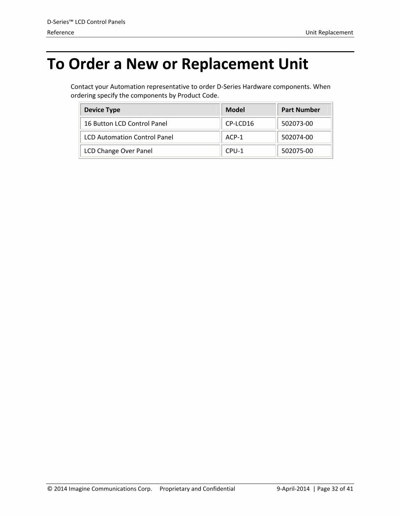
To Order a New or Replacement Unit Contact your Automation representative to order D-Series Hardware components. When ordering specify the components by Product Code.
Device Type Model Part Number
16 Button LCD Control Panel CP-LCD16 502073-00
LCD Automation Control Panel ACP-1 502074-00
LCD Change Over Panel CPU-1 502075-00
© 2014 Imagine Communications Corp. Proprietary and Confidential 9-April-2014 | Page 32 of 41

D-Series™ LCD Control Panels
Reference Reference: Upgrading Firmware
Reference: Upgrading Firmware
About Upgrading Panel Firmware CPC6800-based panels come from the manufacture with their firmware already installed. However, there may be situations that require the firmware to be upgraded on the panel. For field operations there are two ways to do this:
via a Serial Connection
via a TCP/IP Connection. (This is method is faster than the Serial approach and the one most like to be used in the field.)
The Serial and Ethernet methods both use the U-Boot boot loader to perform the upgrade.
Upgrading Firmware via Serial Connection A new version of the firmware can be uploaded to the CPC6800 card over a serial connection. This is significantly slower than using the TCP/IP connection. The terminal emulator program must support binary file transfer using the kermit protocol (such as the Hyperterminal program supplied with most Windows versions).
To Upload new Firmware (Serial)
This procedure assumes the board already has the appropriate version of U-Boot installed.
1. Copy the U-Boot package file cpc6800.pkg (which contains the O/S, file-system and control panel application) to the directory accessible by the terminal emulator.
2. Boot the CPC6800 board to the U-Boot serial download mode.
3. Set switches 7 and 8 of DIP switch 3 to closed/up and open/down respectively, to configure U-Boot for upgrade via serial download.
4. Connect the NULL modem cable and start the terminal emulator program configured for 57600 baud, 8 data bits, no parity, and 1 stop bit.
5. Reset the CPC6800 board (by pressing pushbutton SW1 or cycling power).
The terminal emulator should show the basic U-Boot prompt: U-Boot 1.3.0 (Jul 9 2009 - 16:21:42) Harris CPC6800 - Bootloader Revision 1.0
CPU: Freescale Coldfire MCF5282 (PIN: 20 REV: 01) Reset: External Board: Harris CPC6800 Mode: Test
© 2014 Imagine Communications Corp. Proprietary and Confidential 9-April-2014 | Page 33 of 41

D-Series™ LCD Control Panels
Reference Reference: Upgrading Firmware
DRAM: 16 MB FLASH: 4 MB In: serial
Out: serial Err: serial Net: FEC0 ## Ready for binary (kermit) download to 0x00A00000 at 57600 bps...
6. Start the binary file transfer using kermit mode in the terminal emulator.
• For Hyperterminal invoke the “Send File” dialog with the menu command “Transfer|Send File...”,
• Select the cpc6800.pkg file and protocol “Kermit”, and press the “Send” button).
The file transfer starts (it takes approximately 30 minutes). When the file transfer completes, U-boot copies the package file to flash ROM (This takes an additional 10 minutes). Do not remove power or reset the controller until it reports it is done.
7. Set DIP switch SW3 to the default settings for normal operation (1-6 open/down, switches 7-8 closed/up) and reboot to run the newly downloaded firmware.
Upgrading Firmware via TCP/IP Connection If a TFTP server is available, a new version of the firmware can be uploaded to the CPC6800 card over the Ethernet connection. This is much faster than using a serial connection.
To Upload new Firmware (TCP/IP)
This procedure assumes the board already has the appropriate version of U-Boot installed.
1. Copy the U-Boot package file cpc6800.pkg (which contains the O/S, file-system and control panel application) to the directory served by the TFTP server.
2. Boot the CPC6800 board to the U-Boot console
3. Set switches 7 and 8 of DIP switch 3 to open (down) and closed (up) respectively, to configure U-Boot to wait at the console.
4. Connect the NULL modem cable and start the terminal emulator program configured for 57600 baud, 8 data bits, no parity, and 1 stop bit.
5. Reset the CPC6800 board (by pressing pushbutton SW1 or cycling power).
The terminal emulator should show the basic U-Boot prompt: U-Boot 1.3.0 (Jul 9 2009 - 16:21:42) Harris CPC6800 - Bootloader Revision 1.0 CPU: Freescale Coldfire MCF5282 (PIN: 20 REV: 01) Reset: Power On Low Voltage Board: Harris CPC6800 Mode: Debug
© 2014 Imagine Communications Corp. Proprietary and Confidential 9-April-2014 | Page 34 of 41

D-Series™ LCD Control Panels
Reference Reference: Upgrading Firmware
DRAM: 16 MB FLASH: 4 MB In: serial Out: serial Err: serial Net: FEC0 ->
Network Related U-Boot Environment Variables
There are a number of U-Boot environment variables related to networking. They default to the following values:
NOTE: Currently a support engineer is unlikely to need to change the other U-Boot environmental variables.
Variable Default Description
ethaddr none This must be set to a unique value for each board when U-Boot is installed (see section Setting Ethernet Address under Installing Firmware on New Board). If not set TCP/IP networking will not function.
ipaddr 192.168.101.2 IP address of CPC6800 controller
netmask 255.255.255.0 IP subnet mask for network
gatewayip 192.168.101.1 IP address of gateway (forwards packets to other subnets)
serverip 192.168.101.1 IP address of TFTP server
To Change Environment Settings If these settings are not appropriate, they can be changed with a setenv command (remember to issue a saveenv if the new settings should be permanent).
1. First transfer the package file to the CPC6800 RAM with the command
-> tftpboot $ramaddr cpc6800.pkg Using FEC0 device TFTP from server 192.168.101.1; our IP address is 192.168.101.2 Filename 'cpc6800.pkg'.
© 2014 Imagine Communications Corp. Proprietary and Confidential 9-April-2014 | Page 35 of 41

D-Series™ LCD Control Panels
Reference Reference: Upgrading Firmware
Load address: 0xa00000 Loading: ######################################################## ######################################################## ######################################################## ######################################################## ######################################################## ############################################################################################################# done Bytes transferred = 2253892 (226444 hex) ->
Transferring the file to RAM only takes a few seconds on a typical network. Note: If the CPC6800 is connected to an Ethernet switch, it may block network traffic to the CPC6800 for the first 20-30 seconds after U-Boot starts up.
2. Next, copy the program from RAM to flash ROM with the command
-> run program ................................... done Un-Protected 35 sectors ................................... done Erased 35 sectors Copy to Flash... done ->
This takes approximately 10 minutes. This uses the U-Boot run command to invoke the commands specified in the environment variable program, which copies the just downloaded package file to flash.
IMPORTANT: Do not remove power or reset the controller until it reports it is done.
3. Set DIP switch SW3 to the default settings for normal operation (1-6 open/down, switches 7-8 closed/up) and reboot to run the newly downloaded firmware.
About Rear Panel DIP Switch SW3 Settings The rear panel DIP switch SW3 are easily accessible to end users. They provide 8 bits of configuration that are used to configure serial port baud rate and boot loader operation.
DIP switch SW3 are normally set for normal operation at 38400 baud: switches 1-6 open/down, switches 7-8 closed/up. Control Panel units are typically shipped with the DIP switch in this position once firmware has been installed.
SW3- 1 thru 4: Default Setting Switches 1-4 do not have an assigned function. However, they should be left in the open position as this is the default setting for new functionality assigned to these switches in future firmware releases.
Open = Down
© 2014 Imagine Communications Corp. Proprietary and Confidential 9-April-2014 | Page 36 of 41

D-Series™ LCD Control Panels
Reference Reference: Upgrading Firmware
Closed = Up
SW3-1 SW3-2 SW3-3 SW3-4 Description
Open Open Open Open Default settings for future functionality.
SW3- 5 and SW3-6: Serial Port Baud Rate Switches SW3-5 and SW3-6 control the baud rate used on the serial ports for communicating with a controlling application.
Open = Down
Closed = Up
Note: The setting on switches 5 and 6 does not affect the baud rate used on the diagnostics serial port (which is always 57600 baud). They only affect the ports used to communicate with a controller application.
SW3-5 SW3-6 Baud Rate
Closed Open 9600
Open Closed 19200
Open Open 38400 (the only baud rate supported by DALstation)
Closed Closed 115200
SW3- 7 and SW3-8: Boot loader Operation The rightmost two switches (7 and 8) control the operation of the boot loader.
Open = Down
Closed = Up
SW3-7 SW3-8 Mode Description
Open Open Serial Download to RAM
Used during software development. Similar to Serial download mode, except the downloaded application is simply executed from RAM without first saving a copy in flash ROM.
Closed Open Serial Download Boot loader waits for an application package file to be serially downloaded using Kermit protocol, and then writes it to flash ROM.
Open Closed Boot Loader Console
Used during software development, or to upload new firmware via an Ethernet
© 2014 Imagine Communications Corp. Proprietary and Confidential 9-April-2014 | Page 37 of 41

D-Series™ LCD Control Panels
Reference Reference: Upgrading Firmware
SW3-7 SW3-8 Mode Description
TCP/IP connection. Boot loader waits for commands over the serial console.
Closed Closed Normal Normal operation. Boot loader runs OS and application image from flash ROM.
To Run the New Firmware After the new firmware is copied to RAM (using the tftpboot command), the new firmware image can be run directly from RAM without first copying it to flash ROM with the command:
bootm $ramaddr
The firmware saved in flash remains unchanged, and the controller reverts to running it the next time it is booted with DIP switch SW3 configured for normal operation. This is useful for testing new firmware versions.
© 2014 Imagine Communications Corp. Proprietary and Confidential 9-April-2014 | Page 38 of 41

D-Series™ LCD Control Panels
Reference Reference: Jumpers
Reference: Jumpers
Internal Jumper Settings The internal configuration jumpers provide for configuration that is less accessible to end users. They are typically set at the time a panel is manufactured and installed, and are not normally changed by the end user.
JP5 Active Serial Ports This configuration jumper must be set appropriately to match the intended use of the CPC6800 based panel.
Jumper JP5 configures whether the third serial port is connected to the RS-232 connector (J10) or the second USB/Serial converter (USB-B or J22). JP5 is located just in front of the mounting screw between the RS-232 connection (J10) and the USB connectors.
Normally JP5 is set with the rearmost pins shorted to select the RS-232 connection. This configuration gives maximum flexibility in connecting a single controller to the panel: either of the two RS-422 ports, the RS-232 port or the USB-A connection may be used.
CPU-1 panel Note: The change-over panel (CPU-1) communicates with two controllers (CPU1 and CPU2), so it makes more sense to set JP5 to select the USB connection: this provides a pair of RS-422 ports and a pair of USB connections for the two controllers that communicate with a CPU-1 panel.
JP5 Pins Shorted Third Serial Port Uses
rearmost two pins RS-232
front most two pins USB-B
no connection does not function
J7 Control Panel Configuration This configuration jumper is set appropriately to match the intended use of the CPC6800 based panel.
IMPORTANT: If J7 is configured with an unsupported setting, the panel will configure itself as an LCD16 panel (to provide some minimal functionality).
Header J7 is a 16-pin header located near the top right hand corner of the board. It provides 8 bits of configuration information to the firmware (similar to DIP switch SW3), but this
© 2014 Imagine Communications Corp. Proprietary and Confidential 9-April-2014 | Page 39 of 41

D-Series™ LCD Control Panels
Reference Reference: Jumpers
information is less convenient to change (since this means opening the control panel chassis). A short can be installed across each of the 8 pairs of pins.
The setting of J7 is reported by the firmware on the RS-232 diagnostic console port as a hexadecimal value (so it is possible to determine the setting of J7 without opening the chassis). Each pair of pins defines a binary bit: 0 if open, 1 if shorted. The leftmost pins 1 and 2 are bit 0 (as hex 0x01), and the rightmost pins 15 and 16 are bit 7 (as hex 0x80).
The LCD16 panel should have no pins shorted on J7 (diagnostics report J7=0x00 at start-up).
The ACP-1 panel should have pins 1 and 2 shorted on J7 (diagnostics report J7=0x01 at start-up).
The CPU-1 panel should have pins 3 and 4 shorted on J7 (diagnostics report J7=0x02 at start-up).
The LCD32 panel should have pins 1 and 2, 3 and 4 shorted on J7 (diagnostics report J7=0x03 at start-up). (This panel is not yet available.)
The setting configured on header J7 configures the firmware for different hardware variants of the control panel.
J7 Jumper Settings Hex Value Configuration
ːːːːːːːː (i.e. no shorts) 0x00 LCD16
Sːːːːːːː (pins 1&2 shorted) 0x01 ACP-1
ːSːːːːːː (pins 3&4 shorted) 0x02 CPU-1
SSːːːːːː (pins 1&2, 3&4 shorted) 0x03 LCD32
(This panel is not yet available.)
Any other setting 0x04 – 0xFF Not Currently used
Note: Future releases of the control panel firmware will likely recognize additional J7 configurations for future control panel configurations.
Rarely Used Jumpers Leave the remaining configuration jumpers in their factory default positions unless there is a specific reason to change them. For completeness of information they are listed below in the order they are found on the controller board, going from left to right (with the board oriented so the silkscreen legends read normally).
JP6: Related to expansion panel (leave unconnected).
JP18: Configures how the BDM port (J1) reset signal is connected to the MCF5882 microprocessor (to RSTI or TCLK). It should be configured with the two pins closest to front edge of board shorted.
JP4: Configures whether Ethernet PHY chip interrupt is connected to IRQ6 of MCF5882 microprocessor (leave unconnected).
© 2014 Imagine Communications Corp. Proprietary and Confidential 9-April-2014 | Page 40 of 41

D-Series™ LCD Control Panels
Reference Reference: Jumpers
JP3: Configures serial EEPROM U14 for either read/write or read-only operation (leave unconnected). The EEPROM is used to store the Ethernet MAC address assigned at the time of manufacture (once this is written, JP3 is moved to disable writes).
JP20: Set state of RCON. Configure with pins shorted together (RCON low).
JP21: Set state of JTAG EN. Configure with pins shorted together (JTAG EN low).
JP1: Configures whether RS-422-A port operates full-duplex (able to receive while transmitting). Configure with two rightmost pins shorted together.
JP9: If shorted, connects a120 Ω terminating resistor across receive the lines of the top RS-422 port (RS-422-A). Leave open (no terminating resistor).
JP17: Configures pin assignment of Oxtel quad UART 16C954 (U2). Leave open.
JP2: Configures whether RS-422-B port operates full-duplex (able to receive while transmitting). Configure with two rightmost pins shorted together.
JP10: If shorted, connects a120 Ω terminating resistor across receive the lines of the lower RS-422 port (RS-422-B). Leave open (no terminating resistor).
JP19: Affects addressing. Leave pins shorted together.
JP7: Configures the serial clock rate used with the LCD buttons. JP7 is located near the top right corner of the board (to the right of J7). Short the pins to select the slow clock (1.84 MHz), or leave them open to select the fast clock (3.68 MHz). Leave configured for fast clock (open).
© 2014 Imagine Communications Corp. Proprietary and Confidential 9-April-2014 | Page 41 of 41