d-r gas field products mos compressor
TRANSCRIPT
© C
opyr
ight
201
1
D-R Gas Field ProductsMOS CompressorJan 2, 2013
[Revision: January 2011]
Gary Tas
Global Sales Manager
Gas Field Products - Dresser-Rand

© C
opyr
ight
201
1
Safe Harbor Disclosure
Some of the information contained in this document contains "forward-looking statements". In many cases, you can identify forward-looking statements by terminology such as "may," "will," "should," "expects," "plans," "anticipates," "believes," "estimates," "predicts," "potential," or "continue," or the negative of such terms and other comparable terminology. These forward-looking statements are only predictions and as such inherently included risks and uncertainties. Actual events or results may differ materially as a result of risks facing Dresser-Rand Company (D-R) or actual results differing from the assumptions underlying such statements. These forward-looking statements are made only as of the date of this presentation, and D-R undertakes no obligation to update or revise the forward-looking statements, whether as a result of new information, future events or otherwise. All forward-looking statements are expressly qualified in their entirety by the "Risk Factors" and other cautionary statements included in D-R's annual, quarterly and special reports, proxy statements and other public filings with the Securities and Exchange Commission and other factors not known to D-R. Your decision to remain and receive the information about to be presented to you shall constitute your unconditional acceptance to the foregoing.

© C
opyr
ight
201
1
Gas Field Product Business Unit Overview
© C
opyr
ight
201
1
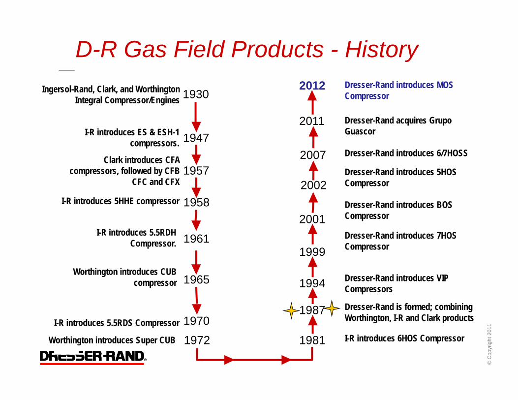
D-R Gas Field Products - History
1930Ingersol-Rand, Clark, and Worthington Integral Compressor/Engines
1947I-R introduces ES & ESH-1 compressors.
1957Clark introduces CFA
compressors, followed by CFB CFC and CFX
1958
1961
1965
1972 1981
1987
I-R introduces 5HHE compressor
I-R introduces 5.5RDH Compressor.
I-R introduces 5.5RDS Compressor
1994
1999
2001
1970
2002
2007
Worthington introduces CUB compressor
Worthington introduces Super CUB I-R introduces 6HOS Compressor
Dresser-Rand is formed; combining Worthington, I-R and Clark products
Dresser-Rand introduces VIP Compressors
Dresser-Rand introduces 7HOS Compressor
Dresser-Rand introduces BOS Compressor
Dresser-Rand introduces 5HOS Compressor
2011
Dresser-Rand introduces 6/7HOSS
Dresser-Rand acquires GrupoGuascor
2012 Dresser-Rand introduces MOS Compressor

© C
opyr
ight
201
1
How Do We Go to Market?
Compressor is “Heart” of Compressor Package Integral to Selection of Driver & Package Equipment
D-R Can Provide Budgetary Estimates & Performance Directly to End Users & EPCs
Network of Authorized Packagers & Distributors Packagers Serve as Technically & Commercially Prime Party
for Firm Quotations
List of Authorized Packagers is Available and Can Be Provided at Request
© C
opyr
ight
201
1
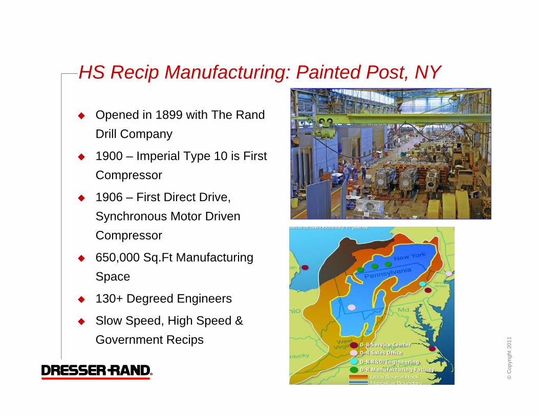
HS Recip Manufacturing: Painted Post, NY
Opened in 1899 with The Rand Drill Company
1900 – Imperial Type 10 is First Compressor
1906 – First Direct Drive, Synchronous Motor Driven Compressor
650,000 Sq.Ft Manufacturing Space
130+ Degreed Engineers
Slow Speed, High Speed & Government Recips

© C
opyr
ight
201
1
Painted Post: Engineering & Testing Capabilities

© C
opyr
ight
201
1
MOS – Product Review
0
2000
4000
6000
8000
10000
12000
0
10,000
20,000
30,000
40,000
50,000
60,000
70,000
80,000
90,000
100,000
A-VIP B-VIP C-VIP MOS HOS HOSS BOS
Hor
sepo
wer
MA
CC
RL
(lbf)
Rod LoadHorsepower

© C
opyr
ight
201
1
MOS: Medium Oilfield Service Compressor
STROKES 5" (127mm) 6" (152.4 mm) 7" (177.8 mm)
THROWS 2 4 6 2 4 6 2 4 6
RATED BHP 1950 3900 4200 1800 3600 4320 1700 3400 4440
Rated kW 1454 2908 3132 1342 2685 3221 1268 2535 3311
RATED SPEED 1500 1200 1000
MACCRL (T OR C) 45,000 LBF (200,170 N)
MACGL (T OR C) 54,000 LBF (240,204 N)

© C
opyr
ight
201
1
Dresser-Rand Frame & Gear Design
Frame Extensions are ribbed to increase rigidity. Frames are
engineered to resist twisting due to gas loading
Frame Extension Side Walls carry load to bearing saddles, which are the stiffest
sections of the frame.
Frame Extensions are integral to frame. This increase rigidity and removes a possible failure joint.
Forged, high-strength alloy steel crankshaft. 2 & 4 Throw have
counterweights designed to minimize horizontal forces & moments.

© C
opyr
ight
201
1
MOS Frame: Designed for Reliability Frame Extensions are Integrally Cast to MB Saddles
Full Floating Crosshead Pins
Precision Bearings
Low Crankshaft Centerline

© C
opyr
ight
201
1
MOS F&G: Designed for Maintainability
Multiple Frame Top Access Doors Lighter & Easier to Handle
Frame Extension Windows on both Sides Access for Two Mechanics
Spin-on Oil Filter
External Oil Pump Relief Valve

© C
opyr
ight
201
1
MOS Compressor: Designed for Efficiency
Benefits of a Longer Stroke Higher Piston Displacement & Lower Clearances @ Equivalent Bore
Cylinders
Higher Volumetric Efficiencies
Higher Cylinder Capacity
Three Strokes: Better Match for Wider Range of Drivers
5” Stroke1400 RPM CAT 3500 Series
6” StrokeGE Waukesha VHP Series
6 Pole – 60 Hz Electric Motors
7” StrokeCAT 3600 & GE 275GL Series Engines
8 Pole – 60 Hz Electric Motors6 Pole – 50 HZ Electric Drives

© C
opyr
ight
201
1
MOS Cylinder Overview Two Cylinder Models Available
Gas Cooled – Low Pressure Water Jacketed – High Pressure Bore Sizes up to 20.50” (HOS Cylinders Available for Larger Bores)
0
500
1000
1500
2000
2500
3000
Cyl
inde
r MAW
P (P
SI)
Cylinder Bore Sizes (in)
Gas Cooled - LPWater Jacketed - HP

© C
opyr
ight
201
1
MOS: Designed for Adaptability Cylinders are Broken into 6 “Classes” Based on Bore Diameter
Each Class has Identical External Cylinder Dimensions
15.00 11.50 8.50 6.5020.50 17.50 14.00 10.50 8.00 6.0019.00 16.25 13.00 9.50 7.50 5.75
12.25 9.00 7.00 4.75
MOS‐B
6‐900#MOS‐A
6‐900#MOS‐F
10-300# MOS‐E
10-300# MOS‐D
8-400# MOS‐C
8-600#
© C
opyr
ight
201
1
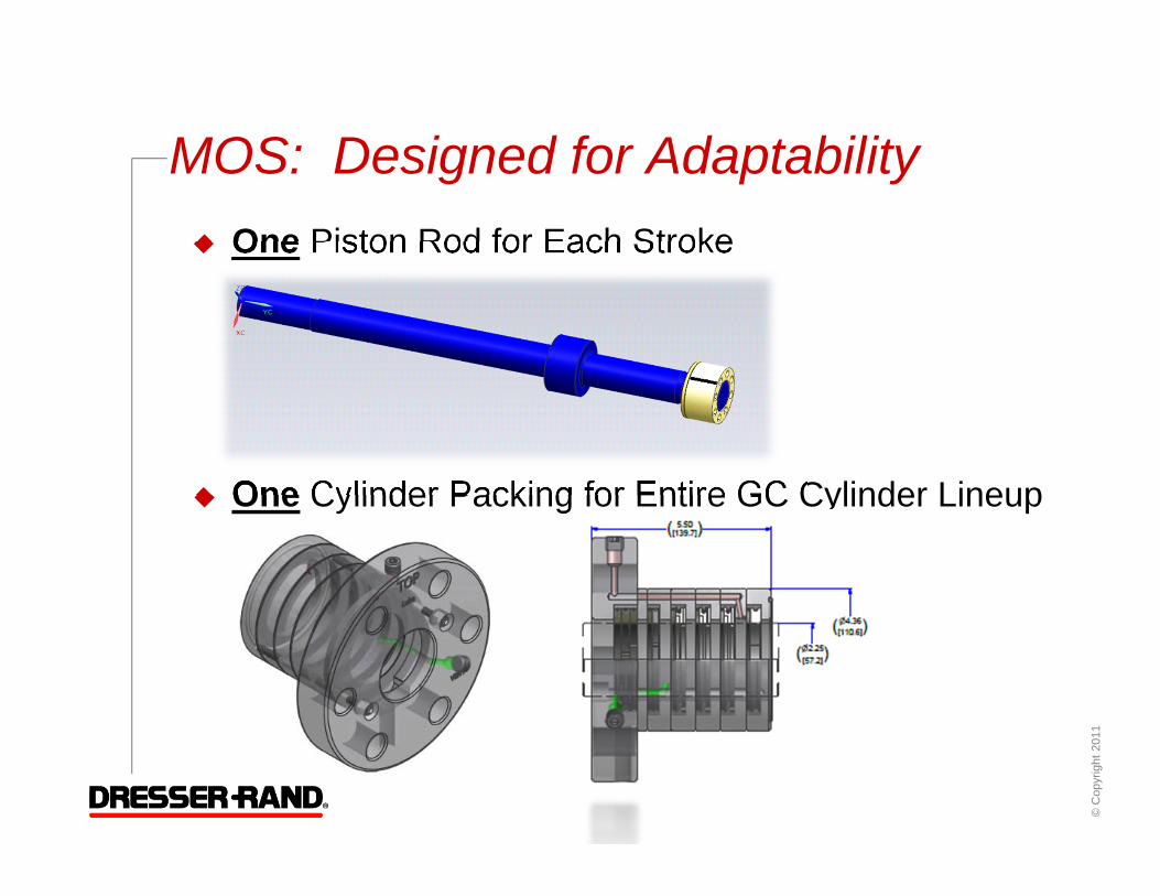
MOS: Designed for Adaptability One Piston Rod for Each Stroke
One Cylinder Packing for Entire GC Cylinder Lineup

© C
opyr
ight
201
1
MOS Cylinders: Designed for Maintainability
Supernut™ piston nut only requires ½” drive wrench
“Conventional” Style Cylinder. No special tools required
Two Dist. Pc. Windows for easy access to Packing

© C
opyr
ight
201
1
MOS – Designed for Efficiency: Fugitive Emissions Control
Hoerbiger’s Balanced Cap Design: Introduced in 2010
70% Reduction in Fugitive Emissions due to Leakage
Reduction in Rod Temperature
Exponential Increase in Ring Life
Improved Static Seaing: Seals While Unit is Shutdown
Emissions Control Ring
© C
opyr
ight
201
1
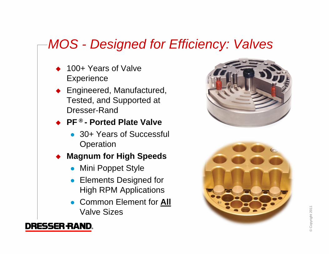
MOS - Designed for Efficiency: Valves
100+ Years of Valve Experience
Engineered, Manufactured, Tested, and Supported at Dresser-Rand
PF ® - Ported Plate Valve 30+ Years of Successful
Operation Magnum for High Speeds
Mini Poppet Style Elements Designed for
High RPM Applications Common Element for All
Valve Sizes
© C
opyr
ight
201
1
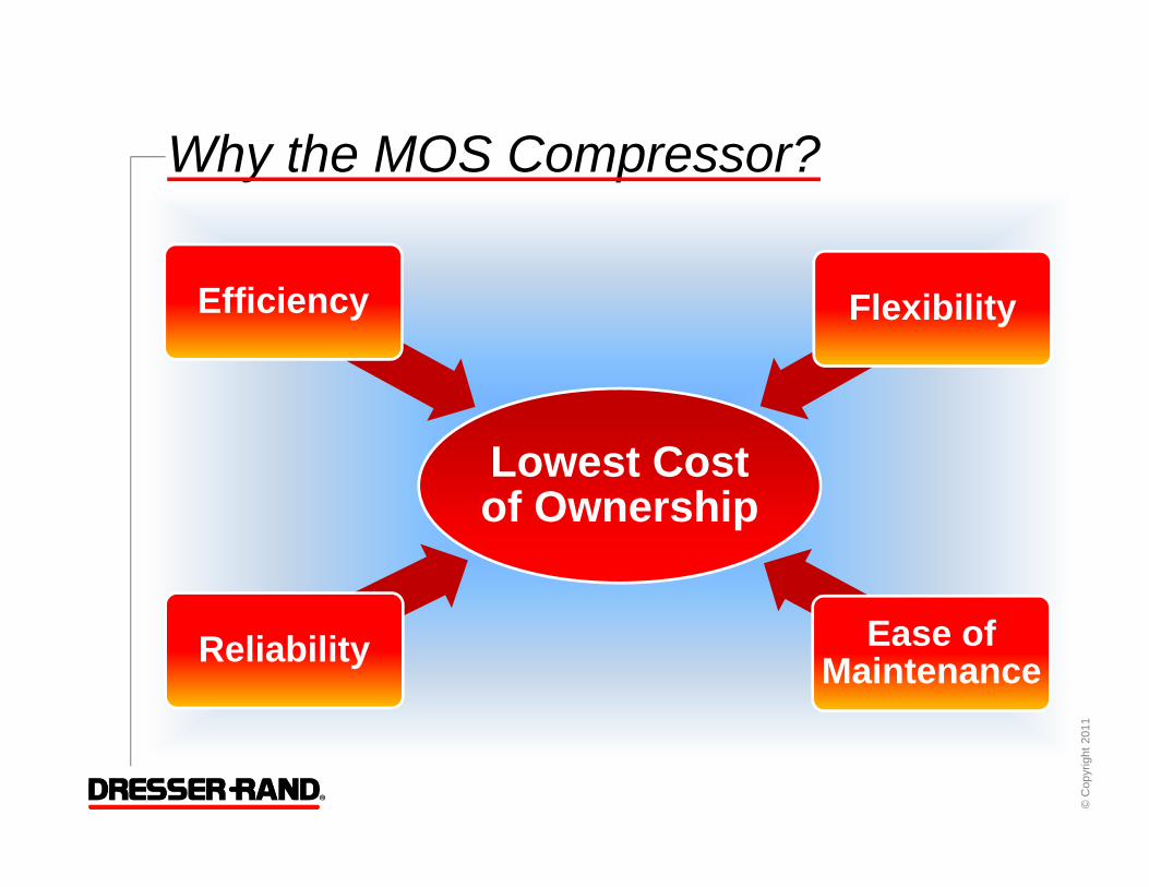
Why the MOS Compressor?
Lowest Cost of Ownership
Reliability
Efficiency Flexibility
Ease of Maintenance