d-r compressor cell rit senior design team p13458 systems design review
TRANSCRIPT

D-R Compressor Cell
RIT Senior Design Team P13458
Systems Design Review

Agenda
Project Introduction Desired Outcome Project Description & Motivation Customer Needs
Systems Design Specifications Concept selection process Systems architecture Concept discussion
Next steps Risk Management Plan Work Breakdown Structure

Desired OutcomeBased on the following specifications and proposed concepts:
Come to a decision on which design to pursue for the remainder of MSD I and MSD II Gain any feedback, recommendations, and direction
Discussion of next steps for detailed design, test, prototyping, etc.

Project Summary Overall goal of project:
Transform the fixed material position assembly process for the gas application reciprocating compressors into a flowing cell layout
Specific Task: Create the material handling system that will allow the
assembly to travel through this cell and will support the lean manufacturing initiatives this project is pursuing
Note: A consultant has created a conceptual design of the process flow through this cell.

Motivations Prepare for a projected increase in demand for
their newly released MOS compressor Break into separable compressor market share
Increase their on-time delivery rating from 35% to 95%
Proposed Productivity/Volume Increase: 150%
Create a safer environment for the operators (no overhead cranes)

Current & Proposed LayoutBuild
Future Flow
Line
The
Mov
e
Test
Paint
Wash
Sub-Assy

Future Layout

Customer Needs
TitlePriority
MultiplierDescription
Safety & Ergonomics
3 Capacity to prevent work-related injury
Cost 2 Upfront Purchase/Installation Cost (capital investment)
Transportability 2 Ease of Motion
Current Capability
1 Compatibility with current facilities
Scale 3 Impact of installation, no monuments allowed
Guidance 2 Ability to remain inline
Flexibility 3 Capacity for systems integration
Maintenance 2 Operational Cost, Frequency of Repairs, Repair Costs
Returnability 2 Ability to return empty fixture to beginning of the line
Ease of Use 2Minimize worker frustration, encourage proper use of the system
Key for Priority Multiplier:1 It would be nice2 Should be incorporated3 Must have, absolutely
necessary

Systems Design Discussion

Specifications
Eng MetricsTarget Value Marginal Value Dir
Safety & Ergonomics
Purchase and Install
CostEase of Motion
Compatable with Facility
Minimize installation
impactGuidance to
remain in lineCapacity for integration Ease of Use
Repair and operation
cost Returnability to startCost per cart $5,000 $10,000 - X X XPeople to move 1 3 - X X X XTime to move 5min 20min - X X XUnits moved 6 1 + X XTime to setup move 0min 10min -Sick bay size 4 2 + X X X X XTime to return 10min 30min - XCart Weight 1500lb 2500lb - X X X XNumber of Carts 18 12 + X X X XForce to move 100lb 500lb + X X X XStays in Line 3ft 5ft + X X XCart Height 18" 16-20" 0 X XPower Sources Required 1 2 - X XStopping distance 5ft 10ft - X XForce to stop 0lb 500lb - XWeight per cart 15T 10T + X X
Customer needsMetric Value

Concept Selection

Concept Selection Translational Motion
Wheeled Cart Industrial casters connected to a frame construct
Air Skids Air bearings connected to a frame construct
Rails are no longer being considered Propulsion
Powered Hand Cart Battery/Electric Air powered
Systems Architecture
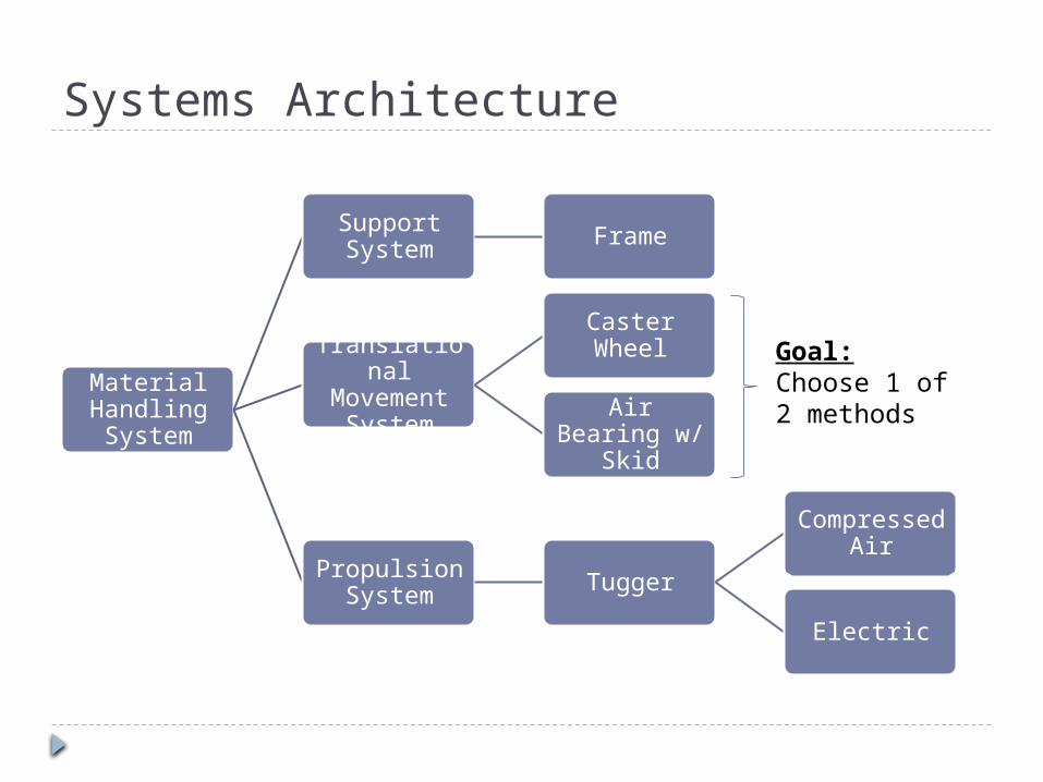
Material Handling System
Support System Frame
Translational Movement
System
Caster Wheel
Air Bearing w/ Skid
Propulsion System Tugger
Compressed Air
Electric
Goal:Choose 1 of 2 methods

Center of GravityDiffering cylinder sizes and loading patterns allow for a range of C.G. locations.
These varying locations must be accounted for in order to avoid hazardous loading conditions.
The maximum CG envelope for the HOS and MOS models from all loading scenarios is shown in red.
The frame design must take into account a factor of safety. This safe CG envelope is shown in yellow.
The frame architecture must support the compressor from outside of the CG envelope.

Support System - Frame Overview A36 Steel square tubing and plate Frame will rest on four wheels or two air skids 90” Long, 30” wide- outside CG envelope Two carts for 2 and 4 throw, three carts for 6-
throw
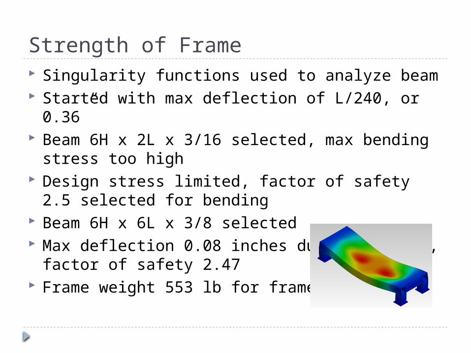
Strength of Frame Singularity functions used to analyze beam Started with max deflection of L/240, or 0.36” Beam 6H x 2L x 3/16 selected, max bending
stress too high Design stress limited, factor of safety 2.5 selected
for bending Beam 6H x 6L x 3/8 selected Max deflection 0.08 inches due to bending, factor
of safety 2.47 Frame weight 553 lb for frame

Frame Design
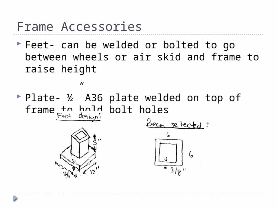
Frame Accessories Feet- can be welded or bolted to go between
wheels or air skid and frame to raise height
Plate- ½” A36 plate welded on top of frame to hold bolt holes

Materials Needed 20 feet 6x6x3/8 steel - $571 4x8x1/2 A36 sheet - $499
Source: metalsdepot.com

Caster Wheel Technology
Swivel Casters
Fixed Casters

Pros & Cons
Pros
Ability to integrate with existing facilities
Ease of movement No power
requirements Low maintenance Cost effective
Cons
Floor surface must be well maintained
Low load capacity with respect to size
Difficulty in directional control
Time intensive directional abilities
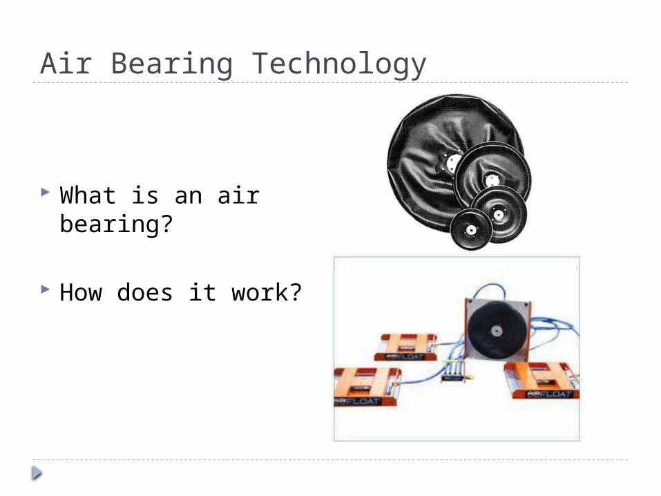
Air Bearing Technology
What is an air bearing?
How does it work?

Pros & Cons
Pros
Ability to integrate with existing facilities
High load carrying capacity
Omni-directional movement
Ease of movement Low power requirements
Cons
Floor surface must be flat, crack free, and well maintained
More costly than conventional wheels and casters
Requires a physical line of air to be connected during movement
Requires an independent system to control movement
Requires employee training
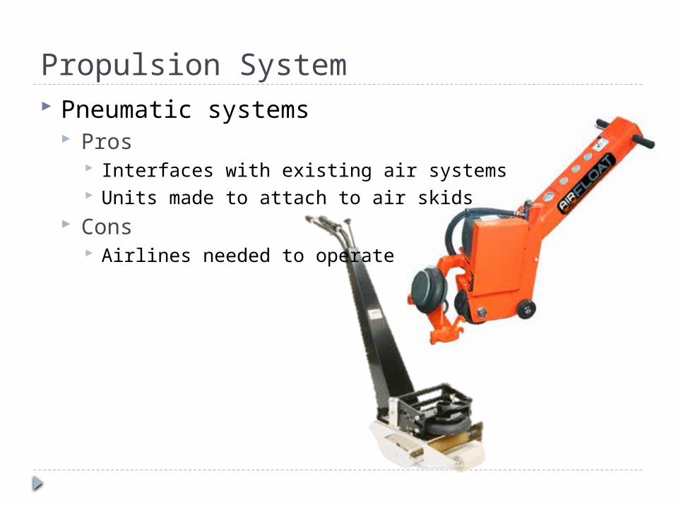
Pneumatic systems Pros
Interfaces with existing air systems Units made to attach to air skids
Cons Airlines needed to operate
Propulsion System

Propulsion Systems Battery powered systems
Pros No airlines needed Can be modified to work with either concept
Cons Need to determine hookup system to cart design Limited battery life

Risk AssessmentID Risk Items Effect Cause Likelihood Severity Importance Action to Minimize Risk
1Supplier Information
delay/unavailableProject delay
Unavailable information, provided information is incomplete, we did not
request the right information
3 2 6Try to find alternate suppliers, be
more specific and constant communication.
2 Room reserve conflictMeeting delay and
unprofessionalPoor communication and bad
Planning3 2 6
Early room reservation and good communication.
3Client contact unavailability
delay project progressSchedule conflict, poor
management and staffi ng changes
2 2 4Early notification/planning and good
communication
4 Falling SickAdditional tasks required to complete by available work
forceFlu, diseases and virus 2 2 4
Vaccination, adequate rest and update teammate with updated
work
Qty
Likelihood scale: Severity scale: Importance Scale: Prevent 4
1 This cause is unlikely ‐to happen
1 The impact on the project ‐is very minor. We will still meet needs on time within budget, but it will cause
This is determined by the product of importance and severity multipliers
Reduce 3
2 This cause could ‐conceivably happen
2 The impact on the project ‐is noticeable.We will deliver reduced functionality, go over budget or fail to meet some of our Engineering Specifications
Transfer 3
3 This cause is very ‐likely to happen
3 The impact on the project ‐is severe.We will not be able to deliver anything, or what we deliver will not meet the customer's needs
Accept 2Accept Low importance risks may not justify any action at all. If
they happen, you simply accept the consequences.
Color CodeRating KeysPrevent Action will be taken to prevent the cause(s) from
occurring in the first place.
Reduce Action will be taken to reduce the likelihood of the cause and/or the severity of the effect on the project, should
the cause occur
Transfer Action will be taken to transfer the risk to something else. Insurance is an example of this. You purchase an
insurance policy that contractually binds an insurance company to pay for your loss in the event of accident. This transfers the financial consequences of the accident to someone else. Your
car is still a wreck, of course.

Project PlanDetailed Design through MSD I and beginning of MSD II.
How far with testing, prototyping, and building should we plan for based on needs and resources?

Additional Questions Do you have any suggestions on lifting ideas
without use of an overhead crane that would integrate with our design?
(For D-R) Do we need to design to incorporate the HOSS models?