d btl5-t1 p-s86-s103 0102 - balluffusa.balluff.com/manuals/btl...
TRANSCRIPT

PROFIBUS-DP
BTL5-T1_ _-M/U_ _ _ _-P-S 86/S 103
Technical DescriptionUser's Guide
english
Balluff GmbHSchurwaldstrasse 973765 Neuhausen a.d.F.GermanyPhone +49 (0) 71 58/1 73-0Fax +49 (0) 71 58/50 10Servicehotline +49 (0) 71 58/1 73-3 70E-Mail: [email protected]://www.balluff.dehttp://www.balluff.dehttp://www.balluff.dehttp://www.balluff.dehttp://www.balluff.de
BTL5-T1_ _-M/U_ _ _ _-P-S 86/S 103Micropulse Linear Transducer – Profile Housing
2 english
Read this manual before installingand operating the Micropulse Trans-ducer.
1.1 Proper application
The BTL5 Micropulse transducer isintended to be installed in a ma-chine or system. Together with aPROFIBUS Master it comprises aposition measuring system and mayonly be used for this purpose.
Unauthorized modifications andnon-permitted usage will result inthe loss of warranty and liabilityclaims.
1.2 Qualified personnel
This guide is intended for special-ized personnel who will perform theinstallation and setup of the system.
1.3 Use and inspection
The relevant safety regulations mustbe followed when using the trans-
1 Safety Advisory
ducer system. In particular, stepsmust be taken to ensure that shouldthe transducer system becomedefective no hazards to persons orproperty can result. This includesthe installation of additional safetylimit switches, emergency shutoffswitches and maintaining the per-missible ambient conditions.
1.4 Scope
This guide applies to the modelBTL5-T1...P... Micropulse trans-ducer.
An overview of the various modelscan be found in Section 6 Versions(indicated on part label) on page 11.
Note: For special versions, whichare indicated by an -SA_ _ _ des-ignation in the part number, othertechnical data may apply (affect-ing calibration, wiring, dimensionsetc.).
Table of Contents
1 Safety Advisory ..................... 21.1 Proper application .................. 21.2 Qualified personnel ................ 21.3 Use and inspection ................ 21.4 Scope ..................................... 2
2 Function andcharacteristics ...................... 3
2.1 Characteristics ....................... 32.2 Function ................................. 32.3 Available stroke lengths
and magnets .......................... 32.4 Using multiple magnets ......... 3
3 Installation ............................ 43.1 Transducer installation ........... 43.2 Floating magnets .................... 63.3 Captive magnets .................... 7
4 Wiring .................................... 84.1 With S 86 connector .............. 94.2 WIth S 103 connector .......... 10
5 Startup ................................. 115.1 Check connections .............. 115.2 Turning on the system .......... 115.3 Check output values ............ 115.4 Check functionality .............. 115.5 Fault conditions .................... 115.6 Noise elimination .................. 11
6 Versions (indicated onpart label) ............................ 11
7 Configuration ...................... 127.1 Default settings .................... 127.2 Presets ................................. 127.3 Configuration with
COM PROFIBUS .................. 127.4 Configuring using Step7 ...... 167.5 General configuration
notes .................................... 207.6 Parameter data ..................... 217.7 I/O configuration .................. 237.8 Diagnostic data .................... 23
8 Technical Data .................... 258.1 Dimensions, weights,
ambient conditions............... 258.2 Supply voltage (external) ...... 258.3 Control signals ..................... 258.4 Connection to the
processor ............................. 258.5 Included in shipment ............ 258.6 Magnets ............................... 258.7 Accessories .......................... 25
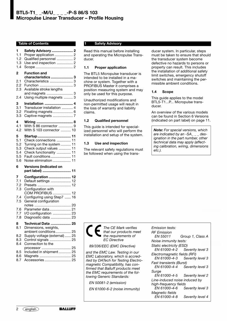
Emission tests:RF Emission
EN 55011 Group 1, Class ANoise immunity tests:Static electricity (ESD)
EN 61000-4-2 Severity level 3Electromagnetic fields (RFI)
EN 61000-4-3 Severity level 3Fast transients (Burst)
EN 61000-4-4 Severity level 3Surge
EN 61000-4-5 Severity level 2Line-induced noise induced byhigh-frequency fields
EN 61000-4-6 Severity level 3Magnetic fields
EN 61000-4-8 Severity level 4
The CE Mark verifiesthat our products meetthe requirements ofEC Directive
89/336/EEC (EMC Directive)
and the EMC Law. Testing in ourEMC Laboratory, which is accred-ited by DATech for Testing Electro-magnetic Compatibility, has con-firmed that Balluff products meetthe EMC requirements of the fol-lowing Generic Standards:
EN 50081-2 (emission)
EN 61000-6-2 (noise immunity)

BTL5-T1_ _-M/U_ _ _ _-P-S 86/S 103Micropulse Linear Transducer – Profile Housing
3english
2.1 Characteristics– High data reliability: output data
are checked in the µC for validityand plausibility.
– Up to 4 positions can be pro-cessed
– Definable working strokes– Absolute output signal– High resolution, repeatability and
linearity– Insensitive to shock, vibration,
contamination and noise– Cable length between transducer
and controller up to 1200 m– Configuration using Step7,
COM-PROFIBUS, WinDP, orother configuration softwarer
– Protected to IP 67 per IEC 529– DIP switches for address setting
The following patents have beengranted in connection with thisproduct:US Patent 5 923 164Apparatus and Method for Auto-matically Tuning the Gain of anAmplifier
2.2 Function
The transducer contains a tubularwaveguide enclosed by an extrudedaluminum housing. A magnet at-tached to the moving member ofthe machine is moved across thetop of the housing and its positionconstantly updated.
The magnet defines the measuredposition on the waveguide. An inter-nally generated INIT pulse interactswith the magnetic field of the mag-net to generate a magnetostrictivetorsional wave in the waveguidewhich propagates at ultrasonicspeed.
The torsional wave arriving at theend of the waveguide is absorbedin the damping zone. The wavearriving at the beginning of thewaveguide creates an electricalsignal in the coil surrounding thewaveguide. The propagation time ofthe wave is used to determine theposition to a resolution of 5 µm.This takes place with high precisionand repeatability at the selectedresolution within the measuringrange indicated as the nominalstroke length.
2 Function and characteristics
Notch on upper housing side marksstart of measuring range
Current magnetposition
Movingmember
Micropulse transducer
Fig. 2-1: Basic configuration
Con
nect
or
Dam
pin
g zo
ne
On both ends of the nominal strokelength is an area which provides anunreliable signal, but which may beentered.
The electrical connection betweenthe transducer, the processor/con-troller and the power supply is via acable, which depending on the ver-sion is either fixed or connectedusing a female connector.
Dimensions for installing theMicropulse transducer and for themagnets and control arm are foundon pages 4 to 7.
2.3 Available stroke lengthsand magnets
To provide for optimum fit in anyapplication, a wide range of stan-dard stroke lengths and magnets invarious form factors are available.Magnets and control arms musttherefore be ordered separately.
The following nominal strokelengths are available:
stroke lengths[mm]
increments[mm]
50 ... 1000 50
1000 ... 2000 100
2000 ... 4000 250
Other stroke lengths on request.
2.4 Using multiple magnets
A minimum spacing of L > 65 mmmust be maintained:
Machine
Nominal stroke =Measuring range
Fig. 2-2: Spacing between magnets
BTL5-T1_ _-M/U_ _ _ _-P-S 86/S 103Micropulse Linear Transducer – Profile Housing
4 english
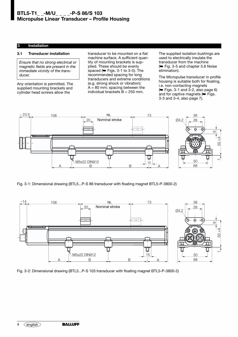
3.1 Transducer installation
Ensure that no strong electrical ormagnetic fields are present in theimmediate vicinity of the trans-ducer.
Any orientation is permitted. Thesupplied mounting brackets andcylinder head screws allow the
3 Installation
transducer to be mounted on a flatmachine surface. A sufficient quan-tity of mounting brackets is sup-plied. These should be evenlyspaced ( Figs. 3-1 to 3-5). Therecommended spacing for longtransducers and extreme conditions(e.g. strong shock or vibration):A = 80 mm; spacing between theindividual brackets B = 250 mm.
The supplied isolation bushings areused to electrically insulate thetransducer from the machine( Fig. 3-5 and chapter 5.6 Noiseelimination).
The Micropulse transducer in profilehousing is suitable both for floating,i.e. non-contacting magnets( Figs. 3-1 and 3-2, also page 6)and for captive magnets ( Figs.3-3 and 3-4, also page 7).
NL
NL
Fig. 3-1: Dimensional drawing (BTL5...P-S 86 transducer with floating magnet BTL5-P-3800-2)
Nominal stroke
Fig. 3-2: Dimensional drawing (BTL5...P-S 103 transducer with floating magnet BTL5-P-3800-2)
Nominal stroke
BTL5-T1_ _-M/U_ _ _ _-P-S 86/S 103Micropulse Linear Transducer – Profile Housing
5english
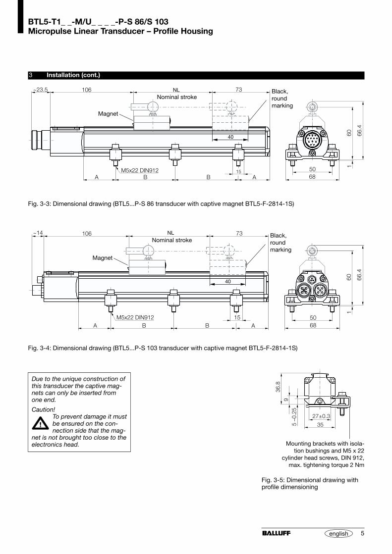
3 Installation (cont.)
Magnet
NL
Magnet
NL
Due to the unique construction ofthis transducer the captive mag-nets can only be inserted fromone end.
Caution!To prevent damage it mustbe ensured on the con-nection side that the mag-
net is not brought too close to theelectronics head.
Nominal stroke
Fig. 3-5: Dimensional drawing withprofile dimensioning
Nominal stroke
Fig. 3-3: Dimensional drawing (BTL5...P-S 86 transducer with captive magnet BTL5-F-2814-1S)
Fig. 3-4: Dimensional drawing (BTL5...P-S 103 transducer with captive magnet BTL5-F-2814-1S)
Mounting brackets with isola-tion bushings and M5 x 22
cylinder head screws, DIN 912,max. tightening torque 2 Nm
Black,roundmarking
Black,roundmarking
BTL5-T1_ _-M/U_ _ _ _-P-S 86/S 103Micropulse Linear Transducer – Profile Housing
6 english
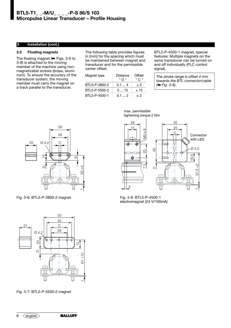
Fig. 3-6: BTL5-P-3800-2 magnet
Fig. 3-7: BTL5-P-5500-2 magnet
3 Installation (cont.)
BTL5-P-4500-1 magnet, specialfeatures: Multiple magnets on thesame transducer can be turned onand off individually (PLC controlsignal).
The stroke range is offset 4 mmtowards the BTL connector/cable( Fig. 3-8).
3.2 Floating magnets
The floating magnet ( Figs. 3-6 to3-8) is attached to the movingmember of the machine using non-magnetizable screws (brass, alumi-num). To ensure the accuracy of thetransducer system, the movingmember must carry the magnet ona track parallel to the transducer.
The following table provides figuresin [mm] for the spacing which mustbe maintained between magnet andtransducer and for the permissiblecenter offset:
Magnet type Distance" D "
Offset" C "
BTL5-P-3800-2 0.1 ... 4 ± 2
BTL5-P-5500-2 5 ... 15 ± 15
BTL5-P-4500-1 0.1 ... 2 ± 2
Connectorwith LED
max. permissibletightening torque 2 Nm
Fig. 3-8: BTL5-P-4500-1electromagnet (24 V/100mA)
BTL5-T1_ _-M/U_ _ _ _-P-S 86/S 103Micropulse Linear Transducer – Profile Housing
7english
3 Installation (cont.)
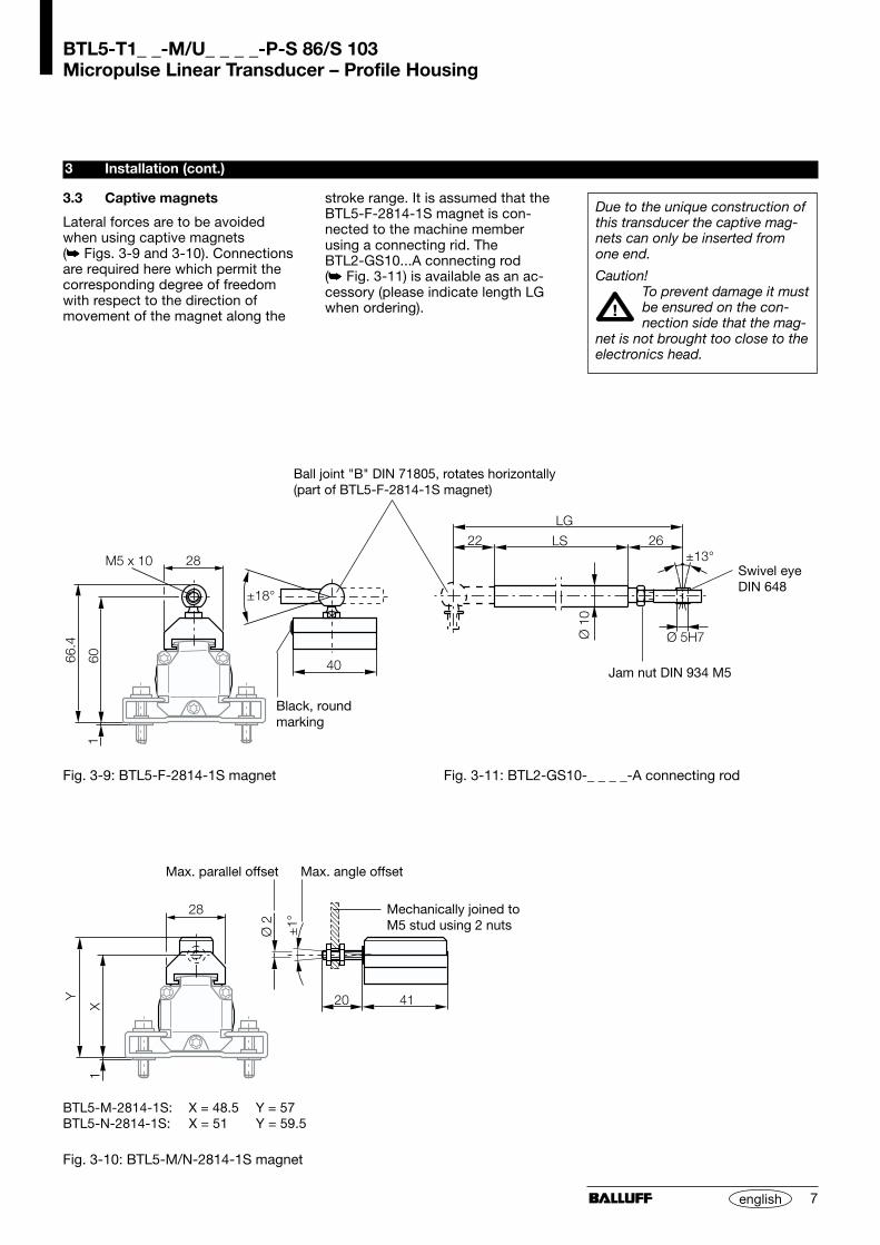
3.3 Captive magnets
Lateral forces are to be avoidedwhen using captive magnets( Figs. 3-9 and 3-10). Connectionsare required here which permit thecorresponding degree of freedomwith respect to the direction ofmovement of the magnet along the
Black, roundmarking
Fig. 3-10: BTL5-M/N-2814-1S magnet
Mechanically joined toM5 stud using 2 nuts
Max. angle offsetMax. parallel offset
stroke range. It is assumed that theBTL5-F-2814-1S magnet is con-nected to the machine memberusing a connecting rid. TheBTL2-GS10...A connecting rod( Fig. 3-11) is available as an ac-cessory (please indicate length LGwhen ordering).
Due to the unique construction ofthis transducer the captive mag-nets can only be inserted fromone end.
Caution!To prevent damage it mustbe ensured on the con-nection side that the mag-
net is not brought too close to theelectronics head.
Ball joint "B" DIN 71805, rotates horizontally(part of BTL5-F-2814-1S magnet)
BTL5-M-2814-1S: X = 48.5 Y = 57BTL5-N-2814-1S: X = 51 Y = 59.5
Fig. 3-11: BTL2-GS10-_ _ _ _-A connecting rod
Jam nut DIN 934 M5
Swivel eyeDIN 648
Fig. 3-9: BTL5-F-2814-1S magnet

BTL5-T1_ _-M/U_ _ _ _-P-S 86/S 103Micropulse Linear Transducer – Profile Housing
8 english
4 Wiring
Note the following when makingelectrical connections:
System and control cabi-net must be at the sameground potential.
To ensure the electromagneticcompatibility (EMC) which Balluffwarrants with the CE Mark, thefollowing instructions must bestrictly followed.
BTL transducer and the proces-sor/control must be connectedusing shielded cable.
Shielding: Copper filamentbraided, 80% coverage.
The shield must be tied to theconnector housing in the BKSconnector ( Fig. 4-4 or Figs.4-8, 4-9, and 4-11); see instruc-tions accompanying the connec-tor.
The cable shield must begrounded on the control side, i.e.,connected to the protectionground.
The Profibus bus line should berouted according to thePROFIBUS Technical Guidelines,Assembly Guideline PROFIBUS-DP/FMS.
Pin assignments can be found in Table 4-2 or in Tables 4-3and 4-4.
When routing the cable between thetransducer, controller and powersupply, avoid proximity to high volt-age lines to prevent noise coupling.
Especially critical is inductive noisecaused by AC harmonics (e.g. fromphase-control devices), againstwhich the cable shield provides onlylimited protection.
The signal is sent to the controllerover the PROFIBUS-DP interface.
Max. cable length of the intire field-bus: 1200 m.
The transmission speed is a func-tion of cable length. EN 50170 isthe reference for the values given in Table 4-1.
Cable length Baud rate [kbps]< 100 m 12,000< 200 m 1,500< 400 m 900
< 1000 m 187.5< 1200 m 93.7 / 19.2 / 9.6
Table 4-1:Baud rate vs. cable length
The bus must be terminated at bothends as per EN 50170. Fig. 4-1or Fig. 4-6.
The BTL5-T provides the optionof assigning the station addressusing DIP switches. For additionalinformation see Section 7 Con-figuration.
BTL5-T1_ _-M/U_ _ _ _-P-S 86/S 103Micropulse Linear Transducer – Profile Housing
9english
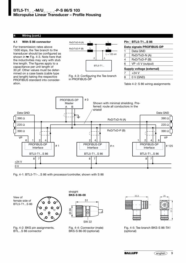
Fig. 4-1: BTL5-T1-...S 86 with processor/controller, shown with S 86
Pin BTL5-T1...S 86
Data signals PROFIBUS-DP1 Data GND2 RxD/TxD-N (A)4 RxD/TxD-P (B)6 VP +5 V (output)
Supply voltage (external)7 +24 V8 0 V (GND)
Table 4-2: S 86 wiring assignments
Fig. 4-2: BKS pin assignments,BTL...S 86 connector
View offemale side ofBTL5-T1...S 86
Fig. 4-3: Configuring the Tee branchin PROFIBUS-DP
1
7 7 7
12 2
A B
24 4 4
RxD/TxD-P (B)
RxD/TxD-N (A)
BTL5-T1...S 86 BTL5-T1...S 86
PROFIBUS-DPMaster
BTL5-T1...S 86
Data GND Data GND
VP VP6
8 8 8
6
390 Ω 390 Ω
390 Ω 390 Ω
220 Ω 220 Ω
+24 V
0 V
# 1 # 125PROFIBUS-DPInterface
PROFIBUS-DPInterface
PROFIBUS-DPInterface
# 0
# n
4 Wiring (cont.)
4.1 With S 86 connector
For transmission rates above1500 kbps, the Tee branch to thetransducer should be configured asshown in Fig. 4-3. Note here thatthe inductivities may vary with stubline length. The figures apply to acapacitance per unit length of30 pF. Other values must be deter-mined on a case basis (cable typeand length) taking the respectivePROFIBUS standard into consider-ation.
Fig. 4-4: Connector (male)BKS-S 86-00 (optional)
straightBKS-S 86-00
Fig. 4-5: Tee branch BKS-S 86-TA1(optional)
Shown with minimal shielding. Pre-ferred: route all conductors in theshield!

BTL5-T1_ _-M/U_ _ _ _-P-S 86/S 103Micropulse Linear Transducer – Profile Housing
10 english
4 Wiring (cont.)
Pin BTL5-T1...S 103
Data signals PROFIBUS-DPBus In / Bus Out
1 VP +5 V (output)2 RxD/TxD-N (A)
3 Data GND4 RxD/TxD-P (B)5 ShieldTable 4-3: Pin assignments, S 103connector
Fig. 4-7: Pin assignments BKS,BTL...S 103 connector
View of male/female side of theBTL5-T1...S 103
4.2 WIth S 103 connector
The connections for supply voltage,Bus In and Bus Out are on separateconnectors in this version.
Fig. 4-6: BTL5-T1-...S 103 with processor/controller, shown with S 103
Fig. 4-11: Connector (male)BKS-S 105-00 (optional)
Pin BTL5-T1...S 103
Supply voltage (external)Power
1 +24 V3 0 V (GND)4 ShieldTable 4-4: Pin assignments, S 103connector
Fig. 4-8: Connector (female)BKS-S 103-00 (optional)
BKS-S103/GS103-CP-...
BKS-S48-15-CP-...
Bus
ter
min
atio
n co
n-ne
ctor
for
IP 6
7 re
-q
uire
d!
(female) (male)
Power(male)
Fig. 4-12: Bus termination resistor(resistors built-in) BKS-S 105-R01(optional)
Fig. 4-9: Connector (female)BKS-S 48-15-CP-__ (optional)
Fig. 4-10: PROFIBUS cable (male/female)BKS-S103/GS103-CP-__ (optional)
BTL5-T1_ _-M/U_ _ _ _-P-S 86/S 103Micropulse Linear Transducer – Profile Housing
11english
5 Startup
5.1 Check connections
Although the connections are polar-ity reversal protected, componentscan be damaged by improper con-nections and overvoltage. Beforeyou apply power, check the con-nections carefully.
5.2 Turning on the system
Note that the system may executeuncontrolled movements when firstturned on or when the transducer ispart of a closed-loop system whoseparameters have not yet been set.Therefore make sure that no haz-ards could result from these situa-tions.
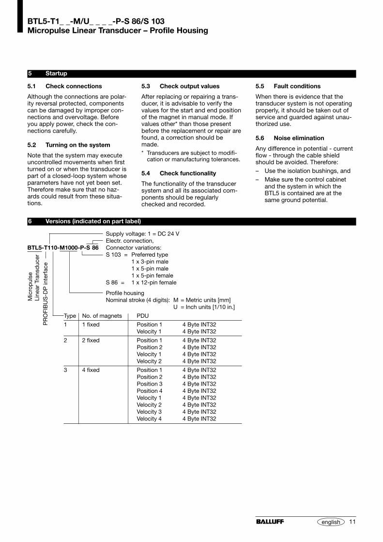
6 Versions (indicated on part label)
Supply voltage: 1 = DC 24 VElectr. connection,
BTL5-T110-M1000-P-S 86 Connector variations:S 103 = Preferred type
1 x 3-pin male1 x 5-pin male1 x 5-pin female
S 86 = 1 x 12-pin female
Profile housingNominal stroke (4 digits): M = Metric units [mm]
U = Inch units [1/10 in.]
Type No. of magnets PDU
1 1 fixed Position 1 4 Byte INT32Velocity 1 4 Byte INT32
2 2 fixed Position 1 4 Byte INT32Position 2 4 Byte INT32Velocity 1 4 Byte INT32Velocity 2 4 Byte INT32
3 4 fixed Position 1 4 Byte INT32Position 2 4 Byte INT32Position 3 4 Byte INT32Position 4 4 Byte INT32Velocity 1 4 Byte INT32Velocity 2 4 Byte INT32Velocity 3 4 Byte INT32Velocity 4 4 Byte INT32
Mic
rop
ulse
Line
ar T
rans
duc
erP
RO
FIB
US
-DP
inte
rfac
e
5.3 Check output values
After replacing or repairing a trans-ducer, it is advisable to verify thevalues for the start and end positionof the magnet in manual mode. Ifvalues other* than those presentbefore the replacement or repair arefound, a correction should bemade.* Transducers are subject to modifi-
cation or manufacturing tolerances.
5.4 Check functionality
The functionality of the transducersystem and all its associated com-ponents should be regularlychecked and recorded.
5.5 Fault conditions
When there is evidence that thetransducer system is not operatingproperly, it should be taken out ofservice and guarded against unau-thorized use.
5.6 Noise elimination
Any difference in potential - currentflow - through the cable shieldshould be avoided. Therefore:– Use the isolation bushings, and– Make sure the control cabinet
and the system in which theBTL5 is contained are at thesame ground potential.
BTL5-T1_ _-M/U_ _ _ _-P-S 86/S 103Micropulse Linear Transducer – Profile Housing
12 english
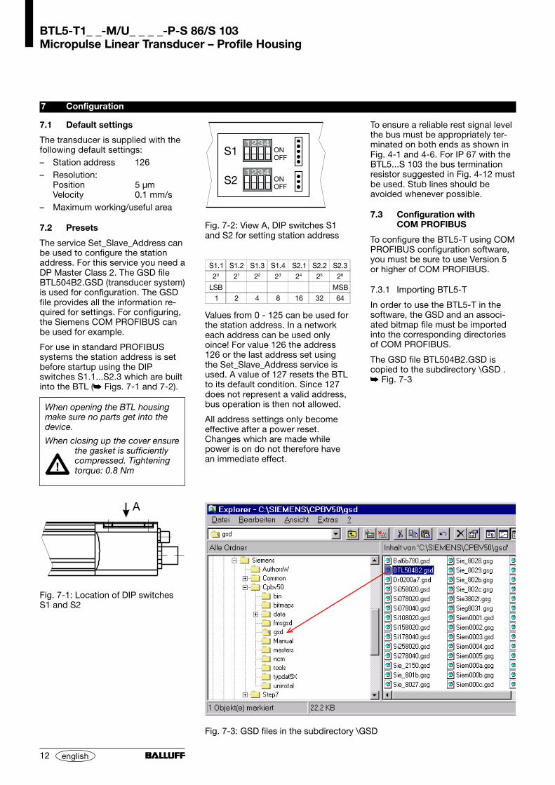
7 Configuration
Fig. 7-2: View A, DIP switches S1and S2 for setting station address
Fig. 7-1: Location of DIP switchesS1 and S2
7.1 Default settings
The transducer is supplied with thefollowing default settings:– Station address 126– Resolution:
Position 5 µmVelocity 0.1 mm/s
– Maximum working/useful area
7.2 Presets
The service Set_Slave_Address canbe used to configure the stationaddress. For this service you need aDP Master Class 2. The GSD fileBTL504B2.GSD (transducer system)is used for configuration. The GSDfile provides all the information re-quired for settings. For configuring,the Siemens COM PROFIBUS canbe used for example.
For use in standard PROFIBUSsystems the station address is setbefore startup using the DIPswitches S1.1...S2.3 which are builtinto the BTL ( Figs. 7-1 and 7-2).
When opening the BTL housingmake sure no parts get into thedevice.
When closing up the cover ensurethe gasket is sufficientlycompressed. Tighteningtorque: 0.8 Nm
Fig. 7-3: GSD files in the subdirectory \GSD
S1.1 S1.2 S1.3 S1.4 S2.1 S2.2 S2.3
20 21 22 23 24 25 26
LSB MSB
1 2 4 8 16 32 64
Values from 0 - 125 can be used forthe station address. In a networkeach address can be used onlyoince! For value 126 the address126 or the last address set usingthe Set_Slave_Address service isused. A value of 127 resets the BTLto its default condition. Since 127does not represent a valid address,bus operation is then not allowed.
All address settings only becomeeffective after a power reset.Changes which are made whilepower is on do not therefore havean immediate effect.
To ensure a reliable rest signal levelthe bus must be appropriately ter-minated on both ends as shown inFig. 4-1 and 4-6. For IP 67 with theBTL5...S 103 the bus terminationresistor suggested in Fig. 4-12 mustbe used. Stub lines should beavoided whenever possible.
7.3 Configuration withCOM PROFIBUS
To configure the BTL5-T using COMPROFIBUS configuration software,you must be sure to use Version 5or higher of COM PROFIBUS.
7.3.1 Importing BTL5-T
In order to use the BTL5-T in thesoftware, the GSD and an associ-ated bitmap file must be importedinto the corresponding directoriesof COM PROFIBUS.
The GSD file BTL504B2.GSD iscopied to the subdirectory \GSD . Fig. 7-3

BTL5-T1_ _-M/U_ _ _ _-P-S 86/S 103Micropulse Linear Transducer – Profile Housing
13english
7 Configuration (cont.)
The bitmap file BTL04B2N.DIB mustbe copied to the subdirectory\BITMAPS. Fig. 7-4
7.3.2 Parameterizing the BTL
After starting COM PROFIBUS theBTL5-T is located in directory\DP-SLAVE\ENCODER\LINEARunder the name BTL5-T (...) and isinserted into the network configura-tion using Drag&Drop. Fig. 7-5
Double clicking on the BTL iconopens the 'Slave Properties' menufor the BTL. Fig. 7-6
Fig. 7-4: Bitmap files in subdirectory \DIB
Fig. 7-5: Adding BTL5-T to the network using Drag&Drop
BTL5-T1_ _-M/U_ _ _ _-P-S 86/S 103Micropulse Linear Transducer – Profile Housing
14 english
7 Configuration (cont.)
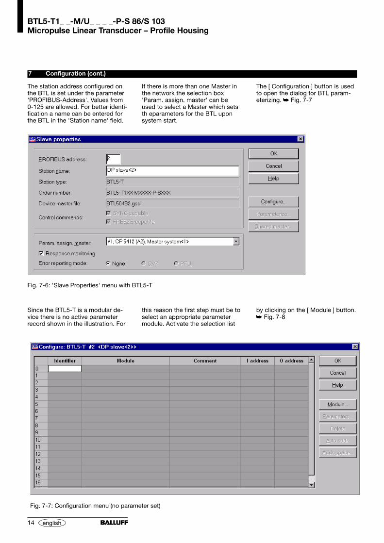
The station address configured onthe BTL is set under the parameter'PROFIBUS-Address'. Values from0-125 are allowed. For better identi-fication a name can be entered forthe BTL in the 'Station name' field.
Fig. 7-6: 'Slave Properties' menu with BTL5-T
Fig. 7-7: Configuration menu (no parameter set)
If there is more than one Master inthe network the selection box'Param. assign. master' can beused to select a Master which setsth eparameters for the BTL uponsystem start.
The [ Configuration ] button is usedto open the dialog for BTL param-eterizing. Fig. 7-7
Since the BTL5-T is a modular de-vice there is no active parameterrecord shown in the illustration. For
this reason the first step must be toselect an appropriate parametermodule. Activate the selection list
by clicking on the [ Module ] button. Fig. 7-8

BTL5-T1_ _-M/U_ _ _ _-P-S 86/S 103Micropulse Linear Transducer – Profile Housing
15english
7 Configuration (cont.)
Double clicking on the desired mod-ule adds it to the configurationtable. Since the BTL is a single-module device, only one modulecan be selected at a time. If a mod-ule was selected previously, theexisting module must be deletedbefore making another selection. Fig. 7-9
Clicking on the [ Parameter ] buttonopens the dialog for device param-eterizing. Fig. 7-10
Fig. 7-8: Module selection
Fig. 7-9: Configuration menu (with parameter data)
BTL5-T1_ _-M/U_ _ _ _-P-S 86/S 103Micropulse Linear Transducer – Profile Housing
16 english
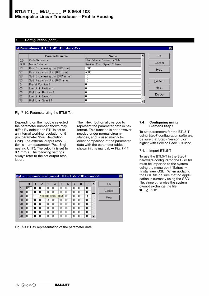
Depending on the module selectedthe parameter number shown maydiffer. By default the BTL is set toan internal working resolution of 5µm (parameter 'Pos. RevolutionUnit'). The external output resolu-tion is 1 µm (parameter 'Pos. Engi-neering Unit'). The velocity is set to0.1 mm/s. The following settingsalways refer to the set output reso-lution.
7 Configuration (cont.)
Fig. 7-10: Parameterizing the BTL5-T...
The [ Hex ] button allows you torepresent the parameter data in hexformat. This function is not howeverneeded under normal circum-stances, and is used mainly fordirect comparison of the parameterdata with the parameter tablesshown in this manual. Fig. 7-11
7.4 Configuring usingSiemens Step7
To set parameters for the BTL5-Tusing Step7 configuration software,be sure that Step7 Version 5 orhigher with Service Pack 3 is used.
7.4.1 Import BTL5-T
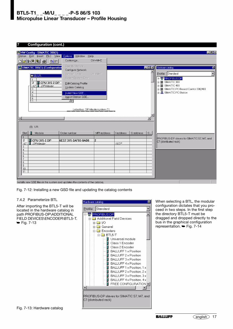
To use the BTL5-T in the Step7hardware configurator, the GSD filemust be imported to the systemusing the menu point 'Extras' 'Install new GSD'. When updatingthe GSD file be sure that no appli-cation is currently using the GSDfile, since otherwise the systemcannot exchange the file. Fig. 7-12
Fig. 7-11: Hex representation of the parameter data
BTL5-T1_ _-M/U_ _ _ _-P-S 86/S 103Micropulse Linear Transducer – Profile Housing
17english
7.4.2 Parameterize BTL
After importing the BTL5-T will belocated in the hardware catalog inpath PROFIBUS-DP\ADDITIONALFIELD DEVICES\ENCODER\BTL5-T. Fig. 7-13
7 Configuration (cont.)
Fig. 7-12: Installing a new GSD file and updating the catalog contents
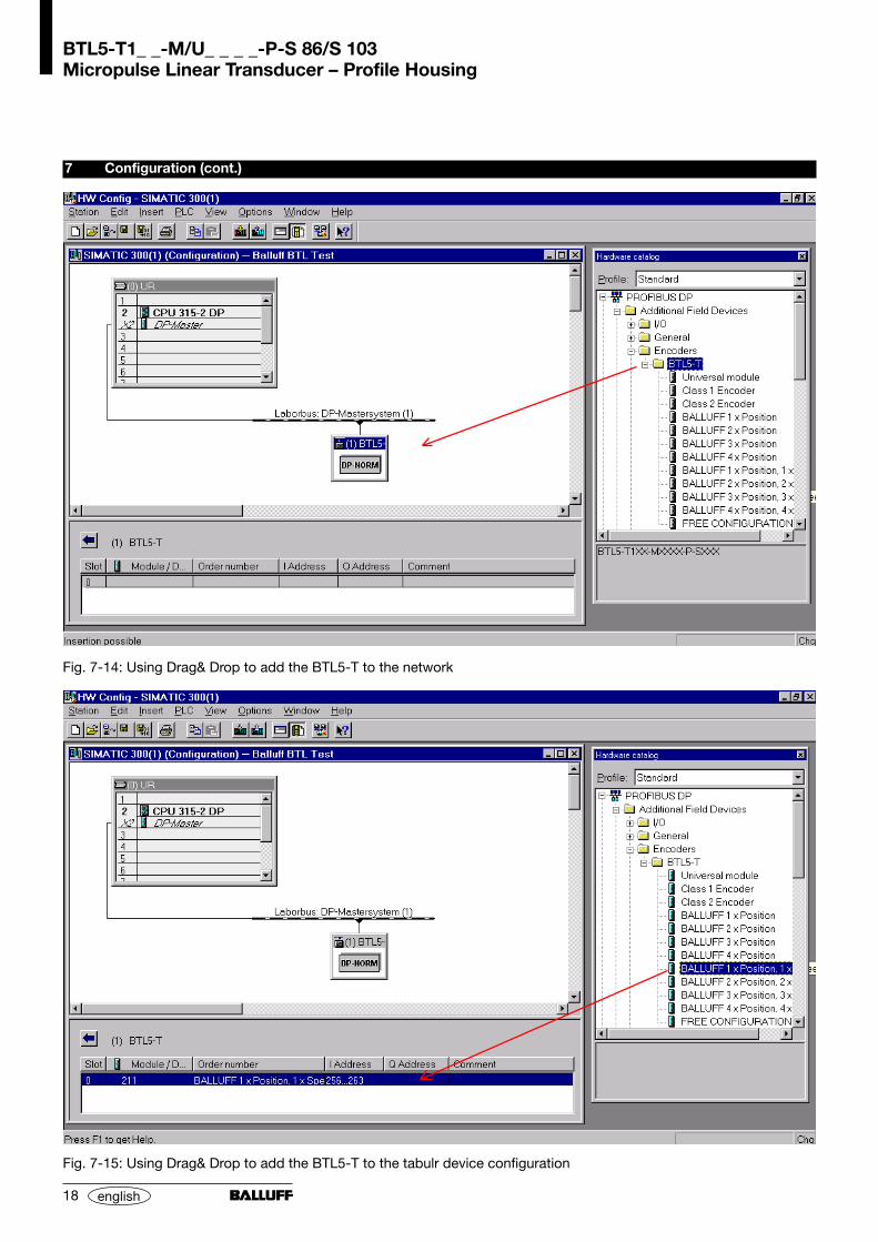
When selecting a BTL, the modularconfiguration dictates that you pro-ceed in two steps. In the first stepthe directory BTL5-T must bedragged and dropped directly to thebus in the graphical configurationrepresentation. Fig. 7-14
Fig. 7-13: Hardware catalog
BTL5-T1_ _-M/U_ _ _ _-P-S 86/S 103Micropulse Linear Transducer – Profile Housing
18 english
7 Configuration (cont.)
Fig. 7-14: Using Drag& Drop to add the BTL5-T to the network
Fig. 7-15: Using Drag& Drop to add the BTL5-T to the tabulr device configuration
BTL5-T1_ _-M/U_ _ _ _-P-S 86/S 103Micropulse Linear Transducer – Profile Housing
19english
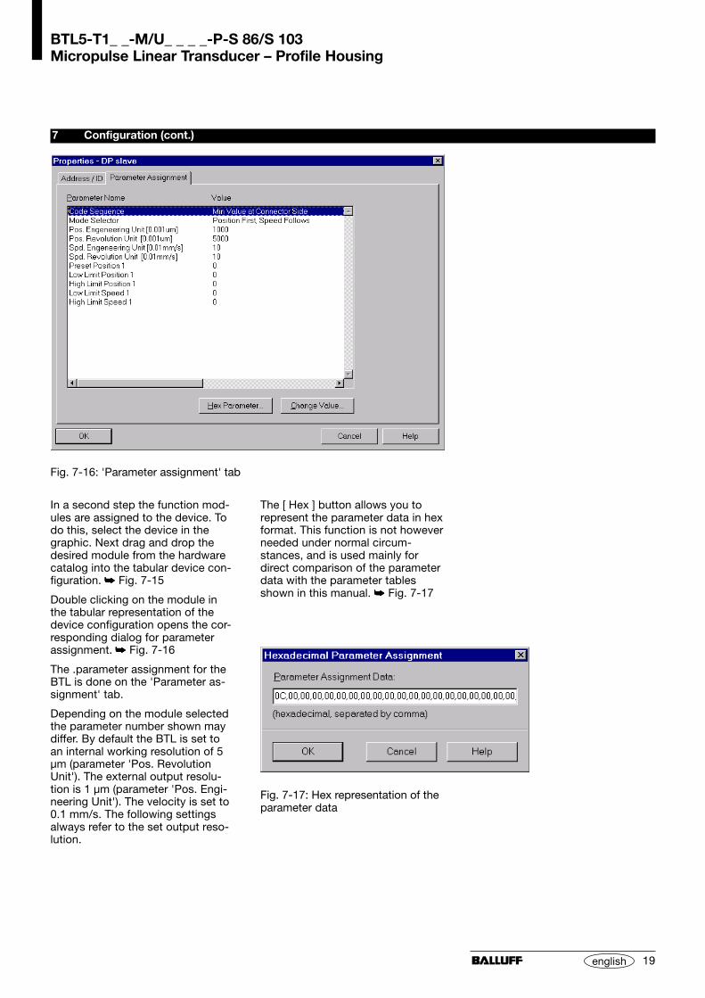
In a second step the function mod-ules are assigned to the device. Todo this, select the device in thegraphic. Next drag and drop thedesired module from the hardwarecatalog into the tabular device con-figuration. Fig. 7-15
Double clicking on the module inthe tabular representation of thedevice configuration opens the cor-responding dialog for parameterassignment. Fig. 7-16
The .parameter assignment for theBTL is done on the 'Parameter as-signment' tab.
Depending on the module selectedthe parameter number shown maydiffer. By default the BTL is set toan internal working resolution of 5µm (parameter 'Pos. RevolutionUnit'). The external output resolu-tion is 1 µm (parameter 'Pos. Engi-neering Unit'). The velocity is set to0.1 mm/s. The following settingsalways refer to the set output reso-lution.
7 Configuration (cont.)
Fig. 7-16: 'Parameter assignment' tab
Fig. 7-17: Hex representation of theparameter data
The [ Hex ] button allows you torepresent the parameter data in hexformat. This function is not howeverneeded under normal circum-stances, and is used mainly fordirect comparison of the parameterdata with the parameter tablesshown in this manual. Fig. 7-17
BTL5-T1_ _-M/U_ _ _ _-P-S 86/S 103Micropulse Linear Transducer – Profile Housing
20 english
7.5 General configurationnotes
If you have problems during startupor configuration of the BTL5-T,check the following points:– The device address used in the
configuration system must agreewith the address set on the BTL.
– The module must be selected toconform with the BTL used. If indoubt, check the BTL part num-ber.
– Depending on the parameterassignment you have performed,both the number and the formatof the output values may vary.
7 Configuration (cont.)
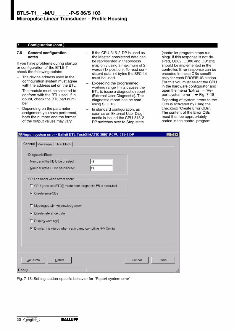
– If the CPU-315-2-DP is used asthe Master, consistend data canbe represented in theprocessmap only using a maximum of 2words (1x position). To read con-sistent data >4 bytes the SFC 14must be used.
– Exceeding the programmedworking range limits causes theBTL to issue a diagnostic report(External User Diagnostic). Thisdiagnostic report can be readusing SFC 13.
– In standard configuration, assoon as an External User Diag-nostic is issued the CPU-315-2-DP switches over to Stop state
(controller program stops run-ning). If this response is not de-sired, OB82, OB86 and OB1212should be implemented in thecontroller. Error response can beencoded in these OBs specifi-cally for each PROFIBUS station.For this you must select the CPUin the hardware configurator andopen the menu 'Extras' 'Re-port system error' . Fig. 7-18Reporting of system errors to theOBs is activated by using thecheckbox 'Create Error OBs'.The content of the Error OBsmust then be appropriatelycoded in the control program.
Fig. 7-18: Setting station-specific behavior for "Report system error'

BTL5-T1_ _-M/U_ _ _ _-P-S 86/S 103Micropulse Linear Transducer – Profile Housing
21english
7 Configuration (cont.)
Octet No. Name Type Description
Standard Encoder Class 1
1 Operation_mode BYTE Bit 0 Code Sequence0 = Lower position values at connector side1 = Higher position values at connector side
Bit 1 Class 2 functionality0 = Disable1 = Enable
Bit 2 Commissioning Diagnostics0 = Disable, No work and speed area monitoring1 = Enable
Bit 3 Scaling Function0 = Disabled, Output resolution always 5 µm1 = Enabled
Bit 4-7 Reserved
Standard Encoder Class22-5 Measuring_Units_Per_Revolution UINT32 Reserved (Class 2)
6-9 Total_Measuring_Range UINT32 Reserved (Class 2)
10-17 Not Defined BYTE Reserved
Balluff Extension18 Mode_Selector BYTE Bit 0-1 Data mapping
0x00 Position first, Speed follows
0x01 Position/Speed alternate
0x02 Speed first, Position follows
Bit 4-7 Max. number of expected magnets, respectively usedmagnets
Resolution Settings19-22 Position_Engineering_Unit UINT32 LSB in steps of 0.001 µm
Default Value = 0x3E8 → 1µm engineering resolution
23-26 Position_Resolution UINT32 LSB in steps of 0.001 µmDefault Value = 0x1388 → 5 µm measurement resolution
27-30 Speed_Engineering_Unit UINT32 LSB in steps of 0.01 mm/sDefault Value = 0x0A → 0.1 mm/s engineering resolution
31-34 Speed_Resolution UINT32 LSB in steps of 0.01 mm/sDefault Value = 0x0A → 0.1 mm/s measurement resolution
Table 7-1a: Parameter data
7.6 Parameter data
BTL5-T1_ _-M/U_ _ _ _-P-S 86/S 103Micropulse Linear Transducer – Profile Housing
22 english
7 Configuration (cont.)
Octet No. Name Type Description
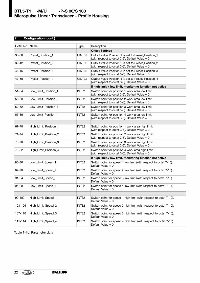
Offset Settings
35-38 Preset_Position_1 UINT32 Output value Position 1 is set to Preset_Position_1(with respect to octet 3-6). Default Value = 0
39-42 Preset_Position_2 UINT32 Output value Position 2 is set to Preset_Position_2(with respect to octet 3-6). Default Value = 0
43-46 Preset_Position_3 UINT32 Output value Position 3 is set to Preset_Position_3(with respect to octet 3-6). Default Value = 0
47-50 Preset_Position_4 UINT32 Output value Position 4 is set to Preset_Position_4(with respect to octet 3-6). Default Value = 0
If high limit = low limit, monitoring function not active
51-54 Low_Limit_Position_1 INT32 Switch point for position 1 work area low limit(with respect to octet 3-6). Default Value = 0
55-58 Low_Limit_Position_2 INT32 Switch point for position 2 work area low limit(with respect to octet 3-6). Default Value = 0
59-62 Low_Limit_Position_3 INT32 Switch point for position 3 work area low limit(with respect to octet 3-6). Default Value = 0
63-66 Low_Limit_Position_4 INT32 Switch point for position 4 work area low limit(with respect to octet 3-6). Default Value = 0
67-70 High_Limit_Position_1 INT32 Switch point for position 1 work area high limit(with respect to octet 3-6). Default Value = 0
71-74 High_Limit_Position_2 INT32 Switch point for position 2 work area high limit(with respect to octet 3-6). Default Value = 0
75-78 High_Limit_Position_3 INT32 Switch point for position 3 work area high limit(with respect to octet 3-6). Default Value = 0
79-82 High_Limit_Position_4 INT32 Switch point for position 4 work area high limit(with respect to octet 3-6). Default Value = 0
If high limit = low limit, monitoring function not active83-86 Low_Limit_Speed_1 INT32 Switch point for speed 1 low limit (with respect to octet 7-10).
Default Value = 0
87-90 Low_Limit_Speed_2 INT32 Switch point for speed 2 low limit (with respect to octet 7-10).Default Value = 0
91-94 Low_Limit_Speed_3 INT32 Switch point for speed 3 low limit (with respect to octet 7-10).Default Value = 0
95-98 Low_Limit_Speed_4 INT32 Switch point for speed 4 low limit (with respect to octet 7-10).Default Value = 0
99-102 High_Limit_Speed_1 INT32 Switch point for speed 1 high limit (with respect to octet 7-10).Default Value = 0
103-106 High_Limit_Speed_2 INT32 Switch point for speed 2 high limit (with respect to octet 7-10).Default Value = 0
107-110 High_Limit_Speed_3 INT32 Switch point for speed 3 high limit (with respect to octet 7-10).Default Value = 0
111-114 High_Limit_Speed_4 INT32 Switch point for speed 4 high limit (with respect to octet 7-10).Default Value = 0
Table 7-1b: Parameter data

BTL5-T1_ _-M/U_ _ _ _-P-S 86/S 103Micropulse Linear Transducer – Profile Housing
23english
7 Configuration (cont.)
Function Data Description
Cfg 0xD1 In 4 BYTE 2 WORDs ofinput dataConsistencyPosition 1
Cfg 0xD3 In 4 BYTE 4 BYTE 4 WORDs ofinput dataConsistency
Position 1 Position 2
Position 1 Speed 1
Speed 1 Position 1
Cfg 0xD5 In 4 BYTE 4 BYTE 4 BYTE 6 WORDs ofinput dataConsistency
Position 1 Position 2 Position 3
Speed 1 Speed 2 Speed 3
Cfg 0xD7 In 4 BYTE 4 BYTE 4 BYTE 4 BYTE 8 WORDs ofinput dataConsistency
Position 1 Position 2 Position 3 Position 4
Position 1 Speed 1 Position 2 Speed 2
Speed 1 Speed 2 Speed 3 Speed 4
Cfg 0xDB In 4 BYTE 4 BYTE 4 BYTE 4 BYTE 4 BYTE 4 BYTE 12 WORDs ofinput dataConsistency
Position 1 Speed 1 Position 2 Speed 2 Position 3 Speed 3
Position 1 Position 2 Position 3 Speed 1 Speed 2 Speed 3
Speed 1 Speed 2 Speed 3 Position 1 Position 2 Position 3
Cfg 9xDF In 4 BYTE 4 BYTE 4 BYTE 4 BYTE 4 BYTE 4 BYTE 4 BYTE 4 BYTE 16 WORDs ofinput dataConsistency
Position 1 Speed 1 Position 2 Speed 2 Position 3 Speed 3 Position 4 Speed 4
Position 1 Position 2 Position 3 Position 4 Speed 1 Speed 2 Speed 3 Speed 4
Speed 1 Speed 2 Speed 3 Speed 4 Position 1 Position 2 Position 3 Position 4
Table 7-2: I/O configuration
7.7 I/O configuration
7.8 Diagnostic data
Octet No. Name Type Description
1-6 PROFIBUS_Standard_Diagnostic OCTET
Encoder Class 1
7 Extended_Diagnostic_Header BYTE Length of the dianostics including the header byte
8 Alarms BYTE Bit 0 Position Error
0 = No1 = Yes
Bit 1 Supply Voltage Error
Bit 2 Current too high Error
Bit 3 Commissioning Diagnostics
Bit 4 Memory Error
Bit 5-7 Reserved
Table 7-3a: Diagnostic data
The number of I/O data is specifiedby the I/O configuration. The data
contents can be specified in theparameter data (Mode_Selector).
7 Configuration (cont.)
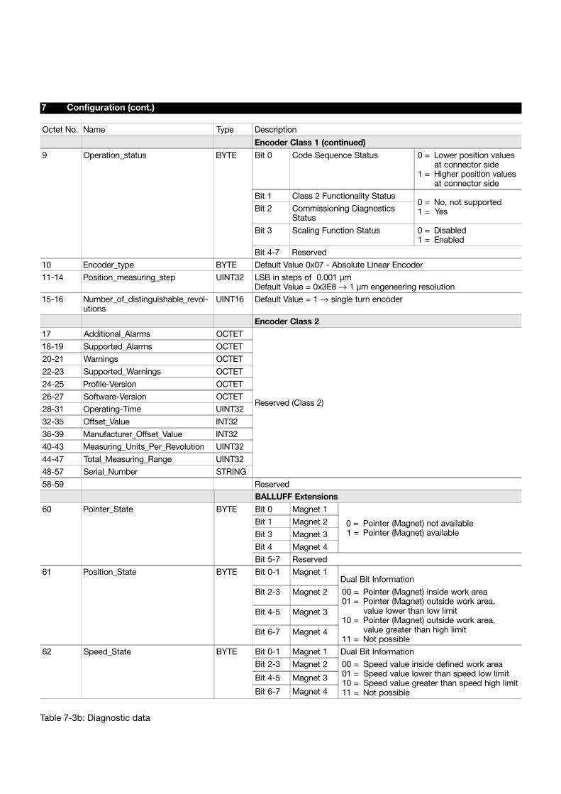
Table 7-3b: Diagnostic data
Octet No. Name Type Description
Encoder Class 1 (continued)
9 Operation_status BYTE Bit 0 Code Sequence Status 0 =
1 =
Lower position valuesat connector sideHigher position valuesat connector side
Bit 1 Class 2 Functionality Status0 =1 =
No, not supportedYesBit 2 Commissioning Diagnostics
Status
Bit 3 Scaling Function Status 0 =1 =
DisabledEnabled
Bit 4-7 Reserved
10 Encoder_type BYTE Default Value 0x07 - Absolute Linear Encoder
11-14 Position_measuring_step UINT32 LSB in steps of 0.001 µmDefault Value = 0x3E8 → 1 µm engeneering resolution
15-16 Number_of_distinguishable_revol-utions
UINT16 Default Value = 1 → single turn encoder
Encoder Class 217 Additional_Alarms OCTET
Reserved (Class 2)
18-19 Supported_Alarms OCTET
20-21 Warnings OCTET
22-23 Supported_Warnings OCTET
24-25 Profile-Version OCTET
26-27 Software-Version OCTET
28-31 Operating-Time UINT32
32-35 Offset_Value INT32
36-39 Manufacturer_Offset_Value INT32
40-43 Measuring_Units_Per_Revolution UINT32
44-47 Total_Measuring_Range UINT32
48-57 Serial_Number STRING
58-59 ReservedBALLUFF Extensions
60 Pointer_State BYTE Bit 0 Magnet 1
0 =1 =
Pointer (Magnet) not availablePointer (Magnet) available
Bit 1 Magnet 2
Bit 3 Magnet 3
Bit 4 Magnet 4
Bit 5-7 Reserved
61 Position_State BYTE Bit 0-1 Magnet 1Dual Bit Information
Bit 2-3 Magnet 2 00 =01 =
10 =
11 =
Pointer (Magnet) inside work areaPointer (Magnet) outside work area,value lower than low limitPointer (Magnet) outside work area,value greater than high limitNot possible
Bit 4-5 Magnet 3
Bit 6-7 Magnet 4
62 Speed_State BYTE Bit 0-1 Magnet 1 Dual Bit Information
Bit 2-3 Magnet 2 00 =01 =10 =11 =
Speed value inside defined work areaSpeed value lower than speed low limitSpeed value greater than speed high limitNot possible
Bit 4-5 Magnet 3
Bit 6-7 Magnet 4
Resolution, selectablein steps of 5 µmVelocity, selectablein steps of 0.1 mm/s
Sampling rate fStandard = 1 kHz
Non-linearity ± 30 µmHysteresis < 1 LSBRepeatability < 2 LSB(resolution + hysteresis)Temperature coefficient< (6 µm + 5 ppm * nominal length)/KShock loading 100 g/6 msper IEC 68-2-27 1
Vibration 12 g, 10 to 2000 Hzper IEC 68-2-6 1
1 Individual specifications as perBalluff factory standard
8.1 Dimensions, weights,ambient conditions
Nominal length < 4000 mmDimensions pages 4 and 5Weight approx. 1.4 kg/mHousing anodized aluminumHousing attachmentMounting clamps with isolationbushings and screwsOperating temp. –40 °C to +85 °CHumidity < 90%, non-condensingProtection class per IEC 529 IP 67when closed up
8.2 Supply voltage (external)
Regulated supply voltageBTL5-_1... DC 20 to 28 VRipple < 0.5 Vpp
Current draw 2 < 130 mAInrush < 3 A/0.5 msPolarity reversal protection built-inOvervoltage protectionTranszorb diodesElectric strengthGND to housing 500 V2 depending on load on VP (repeater,
bus terminator)
8.3 Control signals
RxD/TxD-N, RxD/TxD-P, Data GNDper EN 50170
8 Technical Data
The following are typical values at DC 24 V and 25 °C. Fully operational after power-up, with full accuracy after warm-up. Values are with BTL5-P-3800-2, BTL5-P-4500-1 or BTL5-P-5500-2 magnet held at a constant offset from thetransducer or with captive magnet BTL5-F/M/N-2814-1S (see magnet section for exceptions):
8.4 Connection to theprocessor
Cable Fig. 4-1 bzw. 4-6Twisted-pair, shielded.Max. fieldbus length 1200 m
8.5 Included in shipment
Transducer (with mounting brack-ets, isolation bushings and screws,not incl. magnet) Fig. 3-1 or 3-4GSD file 3.5" floppy
8.6 Magnets(order separately)
Spacing, offset and installation pages 6 and 7
Operating temp. –40 °C to +85 °C
BTL5-P-3800-2 Fig. 3-6Weight approx. 12 gHousing plasticBTL5-F-2814-1S Fig. 3-9Weight approx. 28 gHousing plasticBTL5-M-2814-1S Fig. 3-10Weight approx. 32 gHousing anodized aluminumContact surface plasticBTL5-N-2814-1S Fig. 3-10Weight approx. 35 gHousing anodized aluminumContact surface plastic
BTL5-P-3800-2 andBTL5-F/M/N-2814-1S:
The indicated non-linearity of± 30 µm is valid when the magnetis guided accurately at a constantvertical distance from the trans-ducer within the permissible dis-tance "D".
BTL5-P-5500-2 Fig. 3-7Weight approx. 40 gHousing plasticBTL5-P-4500-1 Fig. 3-8Weight approx. 90 gHousing plasticOperating temp. –40 °C to +60 °C
BTL5-P5500-2 andBTL5-P-4500-1:Recommended resolution
20 µm and aboveNon-linearity < ± 100 µm
The indicated non-linearity of< ± 100 µm is valid when themagnet is guided accurately at aconstant vertical distance fromthe transducer within the permis-sible distance "D".
Control arm (optional)BTL2-GS10-_ _ _ _-AAluminum, dimensions Fig. 3-11Various standard lengths LG avail-able (please specify when ordering)
8.7 Accessories (optional)
8.7.1 ... for BTL5...S 86
Connector BKS-S86-00Dimensions Fig. 4-4
Tee branch BKS-S86-TA1Dimensions Fig. 4-5
8.7.2 ... for BTL5...S 103
For PROFIBUS connections:
Connector BKS-S103-00Dimensions Fig. 4-8
Connector BKS-S105-00Dimensions Fig. 4-9
Cable with connectorBKS-S103/GS103-CP-_ _ _Lengths: 00.3; 02.0; 05.0; 10.0 m
Termination resistorBKS-S105-R01 Fig. 4-12
For power supply:
Cable with connectorBKS-S48-15-CP-_ _Lengths: 02; 05; 10 m
Nr.
817
118
E •
Ed
ition
010
2; s
pec
ifica
tions
sub
ject
to
chan
ges
with
out
notic
e •
Rep
lace
s ed
ition
000
7.