d 5.3 report on compilation for...
TRANSCRIPT

Project Number 288008
D 5.3 Report on Compilation for Time-Predictability
Version 1.027 June 2013
Final
Public Distribution
Vienna University of Technology, Technical University of Denmark,AbsInt Angewandte Informatik, University of York
Project Partners: AbsInt Angewandte Informatik, Eindhoven University of Technology, GMVISSkysoft, Intecs, Technical University of Denmark, The Open Group, University ofYork, Vienna University of Technology
Every effort has been made to ensure that all statements and information contained herein are accurate, however thePartners accept no liability for any error or omission in the same.
© 2013 Copyright in this document remains vested in the T-CREST Project Partners.
D 5.3 Report on Compilation for Time-Predictability
Project Partner Contact Information
AbsInt Angewandte Informatik Eindhoven University of TechnologyChristian Ferdinand Kees GoossensScience Park 1 Potentiaal PT 9.3466123 Saarbrücken, Germany Den Dolech 2Tel: +49 681 383600 5612 AZ Eindhoven, The NetherlandsFax: +49 681 3836020E-mail: [email protected] E-mail: [email protected]
GMVIS Skysoft IntecsJoão Baptista Silvia MazziniAv. D. Joao II, Torre Fernao Magalhaes, 7 Via Forti trav. A5 Ospedaletto1998-025 Lisbon, Portugal 56121 Pisa, ItalyTel: +351 21 382 9366 Tel: +39 050 965 7513E-mail: [email protected] E-mail: [email protected]
Technical University of Denmark The Open GroupMartin Schoeberl Scott HansenRichard Petersens Plads Avenue du Parc de Woluwe 562800 Lyngby, Denmark 1160 Brussels, BelgiumTel: +45 45 25 37 43 Tel: +32 2 675 1136Fax: +45 45 93 00 74 Fax: +32 2 675 7721E-mail: [email protected] E-mail: [email protected]
University of York Vienna University of TechnologyNeil Audsley Peter PuschnerDeramore Lane Treitlstrasse 3York YO10 5GH, United Kingdom 1040 Vienna, AustriaTel: +44 1904 325 500 Tel: +43 1 58801 18227
Fax: +43 1 58801 918227E-mail: [email protected] E-mail: [email protected]
Page ii Version 1.0Confidentiality: Public Distribution
27 June 2013
D 5.3 Report on Compilation for Time-Predictability
Contents
1 Introduction 2
2 Explicit Control of Patmos Components 3
2.1 Method Cache . . . . . . . . . . . . . . . . . . . . . . . . . . . . . . . . . . . . . . 3
2.1.1 Method Cache Background . . . . . . . . . . . . . . . . . . . . . . . . . . . 3
2.1.2 Function Splitting Foundations . . . . . . . . . . . . . . . . . . . . . . . . . 4
2.1.3 Function Splitting . . . . . . . . . . . . . . . . . . . . . . . . . . . . . . . 4
2.1.4 Future Directions . . . . . . . . . . . . . . . . . . . . . . . . . . . . . . . . 8
2.2 Stack Cache . . . . . . . . . . . . . . . . . . . . . . . . . . . . . . . . . . . . . . . 8
2.2.1 Future Directions . . . . . . . . . . . . . . . . . . . . . . . . . . . . . . . . 10
2.3 Data Scratchpad Memory (SPM) . . . . . . . . . . . . . . . . . . . . . . . . . . . . 11
2.3.1 Constant Latency . . . . . . . . . . . . . . . . . . . . . . . . . . . . . . . . 11
2.3.2 Accessing the SPM . . . . . . . . . . . . . . . . . . . . . . . . . . . . . . . 11
2.3.3 DMA Controller . . . . . . . . . . . . . . . . . . . . . . . . . . . . . . . . 11
2.3.4 SPM as a Replacement for Cache . . . . . . . . . . . . . . . . . . . . . . . 12
2.3.5 SPM Alongside Cache . . . . . . . . . . . . . . . . . . . . . . . . . . . . . 13
2.3.6 Modifying Programs to use SPM . . . . . . . . . . . . . . . . . . . . . . . . 14
2.3.7 Limitations . . . . . . . . . . . . . . . . . . . . . . . . . . . . . . . . . . . 15
2.3.8 SPM Buffer API . . . . . . . . . . . . . . . . . . . . . . . . . . . . . . . . 15
2.3.9 Address Space Attributes . . . . . . . . . . . . . . . . . . . . . . . . . . . . 16
2.4 Code Generation for VLIW . . . . . . . . . . . . . . . . . . . . . . . . . . . . . . . 17
3 Single-Path Code Generation 19
3.1 Overview . . . . . . . . . . . . . . . . . . . . . . . . . . . . . . . . . . . . . . . . 20
3.2 Control Dependence Analysis . . . . . . . . . . . . . . . . . . . . . . . . . . . . . 20
3.3 Single-Path Scopes and the Single-Path Scope Tree . . . . . . . . . . . . . . . . . . 23
3.4 Single-Path Loops . . . . . . . . . . . . . . . . . . . . . . . . . . . . . . . . . . . . 25
3.4.1 If-conversion of Loops . . . . . . . . . . . . . . . . . . . . . . . . . . . . . 25
3.4.2 Input-data Independent Iteration Count . . . . . . . . . . . . . . . . . . . . 26
3.5 Predicate Register Allocation . . . . . . . . . . . . . . . . . . . . . . . . . . . . . . 27
3.6 Linearisation of the Control-Flow Graph . . . . . . . . . . . . . . . . . . . . . . . . 28
3.7 Future Directions . . . . . . . . . . . . . . . . . . . . . . . . . . . . . . . . . . . . 30
27 June 2013 Version 1.0Confidentiality: Public Distribution
Page iii

D 5.3 Report on Compilation for Time-Predictability
4 Integration of Compiler and WCET Analysis 334.1 Compilation Flow and Preservation of Meta-Information . . . . . . . . . . . . . . . 33
4.2 Information Exchange Language and the Platin Tool Kit . . . . . . . . . . . . . . . 35
4.3 AbsInt aiT Integration . . . . . . . . . . . . . . . . . . . . . . . . . . . . . . . . . . 35
4.4 Example . . . . . . . . . . . . . . . . . . . . . . . . . . . . . . . . . . . . . . . . . 36
4.5 Future Directions . . . . . . . . . . . . . . . . . . . . . . . . . . . . . . . . . . . . 37
5 Requirements 415.1 Industrial Requirements . . . . . . . . . . . . . . . . . . . . . . . . . . . . . . . . . 41
5.2 Technology Requirements . . . . . . . . . . . . . . . . . . . . . . . . . . . . . . . 43
6 Conclusion 44
Page iv Version 1.0Confidentiality: Public Distribution
27 June 2013
D 5.3 Report on Compilation for Time-Predictability
Document Control
Version Status Date0.1 First outline. 15 March 20130.2 Sections about stack cache
and method cache.28 May 2013
0.3 Description of single-pathtransformation.
31 May 2013
0.4 Description of WCETanalysis integration and SPM
support.
5 June 2013
0.5 Pre-final version, requestingpartner comments.
11 June 2013
1.0 Final version 27 June 2013
27 June 2013 Version 1.0Confidentiality: Public Distribution
Page v

D 5.3 Report on Compilation for Time-Predictability
Page vi Version 1.0Confidentiality: Public Distribution
27 June 2013

D 5.3 Report on Compilation for Time-Predictability
Executive Summary
This document describes the deliverable D5.3 Report on Compilation for Time-Predictability of workpackage 5 of the T-CREST project, due 21 months after project start as stated in the Description ofWork. The deliverable comprises the documentation about compiler technologies used to generatetime-predictable code, such as realisation of single-path code generation, patterns for code gener-ation, and explicit control of Patmos components. We present the single-path code transformationalgorithm and the function splitter algorithm that have been implemented in the compiler. This reportalso discusses how the compiler generates code for the time-predictable stack cache and how the toolchain supports the WCET analysis by transforming and generating code annotations.
27 June 2013 Version 1.0Confidentiality: Public Distribution
Page 1
D 5.3 Report on Compilation for Time-Predictability
1 Introduction
For real-time applications, it is important to be able to derive the worst-case execution time (WCET)of the involved tasks in order to be able to analyse the timing behaviour and to guarantee safe opera-tion of the whole system A worst-case analysis must not only consider the timing-relevant propertiesof the application code itself, but also of the whole platform on which the application is executed. Theplatform consists of several components: a processor core, memory controller and on-chip memories,but also an operating system and system libraries, all of which affect the execution time. The binaryexecutable that needs to be analysed is generally not written by hand but generated by a compiler.
As discussed in previous reports, features designed to improve the average case performance oftraditional hardware platforms impose a number of problems upon the WCET analysis, leading tohigh pessimism of WCET bounds. Dynamic behaviour of both the software and the hardware incombination with large hardware state spaces leads to a state explosion, making it infeasible to trackall possible states of the system under analysis. The timing of operations may depend on the hardwarestate though. The absence of precise state information therefore makes a precise timing analysis ofsuch operations impossible. In the T-CREST project our goal is to develop a platform that not onlyenables a WCET analysis to yield tight WCET bounds but also delivers a high performance.
However, it is not sufficient to improve just a single component of existing application platformsin order to achieve both a time-predictability and high performance. Instead, all components ofthe platform must be designed to be predictable and need to play together to reach that goal. InT-CREST, we therefore envision a platform, where amongst others the compiler, the processor, thememory hierarchy and the WCET analysis are tightly integrated.
In this report we focus on the compiler that generates code for the T-CREST platform and highlightboth the code generation strategies as well as the interaction with the Patmos processor, the memoryhierarchy and the WCET analysis.
We tackle the problem of the large hardware state space by giving the software explicit control overthe hardware state of the processor. This makes the timing of operations far less dependent on thehistory of previous operations, but requires the compiler to generate code that actually controls thehardware in an efficient way. In turn, this enables new hardware designs that can profit from thehigh-level view of the compiler, such as the stack cache or the method cache.
As an approach to reduce the dynamic behaviour of the application software, we implemented asingle-path code transformation pass in the compiler. This allows the compiler to eliminate inputdependent control flow in the application, and thus effectively removes any timing variability of thereal-time tasks from normal application code.
Finally, we improve the WCET analysis precision by providing compiler-internal information to theWCET analysis that is lost after code generation by traditional compilers. We developed a set of toolsthat transform flow information and pass information between the WCET analysis and the compiler.
The rest of the document is structured as following: Section 2 shows how the compiler generates codeto explicitly control the Patmos hardware, specifically the method cache and stack cache, the scratchpad, as well as code generation for the VLIW architecture. In Section 3 we present the single-pathcode generation algorithm that has been implemented into the Patmos compiler. Section 4 describesthe integration of the compiler and the WCET analysis. Section 5 contains a list of the requirements
Page 2 Version 1.0Confidentiality: Public Distribution
27 June 2013
D 5.3 Report on Compilation for Time-Predictability
identified in the early project phase, and describes how they are addressed at the current state. Weconclude this report in Section 6.
2 Explicit Control of Patmos Components
Generating efficient time-predictable code requires a hardware that is time-predictable and providesmechanisms to control the hardware state, as well as a compiler that emits code that controls the hard-ware state in a deterministic way. The tight interaction between the code generated by the compilerand the hardware together with the high-level view on the application of the compiler enables moreadvanced ways of hardware state control, such as caching whole stack frames or function regions.
Precise cache prediction is important for time-predictability due to the high miss penalties, especiallyon a multi-core setup where the available memory bandwidth is shared by many cores. The Patmosprocessor provides a number of different, specialised local memories, which enable high memorythroughput by making use of efficient DMA-controlled burst transfers, but require support from thecompiler. Those local memories are the stack cache (for caching stack frames), the method cache (forcaching instructions) and the scratchpad memory (to keep frequently used data local to the processor),as well as an LRU data cache that can be bypassed. The individual local memories have already beenpresented in previous reports. In the following sections we will describe how the compiler generatescode to control those memories.
Furthermore, Patmos features a fully predicated VLIW architecture, for which the compiler mustschedule instructions statically. Instead of dynamic branch prediction and out-of-order execution, thecompiler performs static scheduling and makes use of speculative execution of code.
2.1 Method Cache
In contrast to traditional instruction caches, the method cache does not manage individual instructionwords, but holds entire blocks of code of variable size, e.g., an entire function. The size of thesecode blocks is limited by the size of the method cache. The compiler thus has to ensure that all codeblocks that will be processed by the method cache fit into the cache. In other words, large functionsand sometimes even basic blocks within functions have to be split.
We thus implemented a splitting strategy (briefly mentioned in the previous deliverable D5.2 [24])that exploits graph theoretical properties of the compiler intermediate representation – namely thecontrol-flow graph.
2.1.1 Method Cache Background
The method cache, similar to a standard cache, loads code blocks as needed during the execution of aprogram. In contrast to a standard cache, however, the cache accesses are guaranteed to be hits exceptfor specific branch (brcf), call (call) and return (ret) instructions. When executing on of theseinstructions, the method cache is queried whether the code block at the target address is availablein the cache. If this is the case, the execution continues without interruption at the beginning of the
27 June 2013 Version 1.0Confidentiality: Public Distribution
Page 3
D 5.3 Report on Compilation for Time-Predictability
target code block within the method cache. In the other case, the method cache starts loading therespective code block (potentially evicting other code blocks) and stalls the processor pipeline untilthe entire code block has been loaded. The execution then continues as before.
It is important to note that the transfer from one code block into another is only possible to thebeginning of the target block, due to the design of the branch and call instructions.
2.1.2 Function Splitting Foundations
The function splitting operates on a compiler intermediate representation called the control-flowgraph. Since our approach exploits some graph theoretical properties of this representation we startby giving a few basic definitions:
Control-flow Graphs: The control-flow graph (CFG) is a compiler intermediate representation,where nodes in the graph represent so-called basic blocks and edges the potential flow of execution ofthe program at runtime from one basic block to another. A basic block is a sequences of instructionssuch that whenever the first instruction in the sequence executes all other instructions execute as well,i.e., the sequence does not contain branches except at its very end (accounting for branch delay slots).Furthermore, only the first instruction of as basic block is the target of branches, i.e., when a basicblock is executed all its instruction execute. We assume that the CFG of a function has a unique entrypoint, the so-called root node.
Dominator: A node u in the CFG dominates another node v, when all paths from the CFG’s rootnode to v go through u. Node u is then called a dominator.
Strongly Connected Component: A strongly connected component (SCC) is a subset of nodes inthe CFG such that a path exists from every node in the subset to every other node in the subset. TheCFG can be decomposed into its strongly connected components. We then call an SCC trivial whenit represents a single node without a self-cycle. All other forms of SCCs are called non-trivial.
Loop Header: We call a node a loop header, when it is part of a non-trivial SCC and a path existsthat leads from the CFG’s root to the node without passing through any other node in the same SCC.Note that several loop headers may exist within an SCC. An SCC that has a unique loop header iscalled a natural loop, all other forms of SCCs are called non-natural loops. A CFG is called reduciblewhen all SCCs are natural loops.
Back Edge: A back edge is an edge leading from a node within an SCC to one of the SCC’s loopheaders.
2.1.3 Function Splitting
We can now model the function splitting problem as a partitioning problem on the control-flow graphof a function. The graph has to be partitioned into subsets, that we call regions, such that:
• The total code size of each region is smaller than the size of the method cache.• Each region has a distinguished node, the region header.• The source and destination of CFG edges are either both in the same region or the destination
node is a region header.
Page 4 Version 1.0Confidentiality: Public Distribution
27 June 2013
D 5.3 Report on Compilation for Time-Predictability
BB0
BB1 BB2
BB3 BB4
BB5
(a) Original CFG
BB0
BB1 BB2
BB3 BB4
BB5
(b) Regions of the CFG
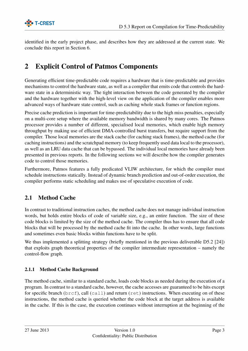
Figure 1: A simple control-flow graph and a possible partitioning into three regions.
Example 1. Consider, for example, control-flow graph and its partitioning into three regions depictedin Figure 1. The first partition consists of the region header BB0 and basic blocks BB1, BB2, andBB4. The other two regions are singletons, consisting only of their region headers BB3 and BB5respectively. Note that all control-flow edges from one region into another always lead to the regionheader of the destination region.
It follows from these properties that a region header has to dominate all the other nodes within theregion.
Lemma 1. For every valid partitioning of a function’s CFG into regions, the region headers domi-nates all nodes of their respective region.
Acyclic CFGs: Using this Lemma, we can easily solve the partitioning problem using a simpletopological graph traversal on acyclic CFGs. The traversal starts with the CFG’s root node, whichby definition has to be a region header. During the traversal we grow regions as much as possibleby adding the newly visited nodes. Whenever a node is visited, all its predecessors in the CFG havealready been assigned to a region. We thus can decide locally whether the node can be added to theregion (a region grows) or whether the node has to become a region header on its own. The node canbe added to an existing region if:
• All predecessors are member of the same region• and the region’s size does not exceed the size of the method cache when adding the node.
Note that in certain cases additional branches have to be inserted into the program in order to ensurethe proper transition between two distinct regions. This bookkeeping can be easily integrated withthe approach from above.
Example 2. Considering a method cache with 4 words in size and the acyclic CFG of Figure 1,where all basic blocks are assumed to be 1 word in size, the splitting algorithm from above proceedsas follows. The CFG’s root node BB0 is visited first, its region thus for now has size 1. We thenvisit BB1. As it fits into the region of its unique predecessor BB0, that region grows to size 2 byadding BB1 to it. Next, BB2 is visited, which can again be added to the region of BB0, which bynow has grown to size 3. The algorithm then visits BB4, which has two predecessors. Both of themare assigned to the same region. The region furthermore is of size 3, which means we still can grow
27 June 2013 Version 1.0Confidentiality: Public Distribution
Page 5

D 5.3 Report on Compilation for Time-Predictability
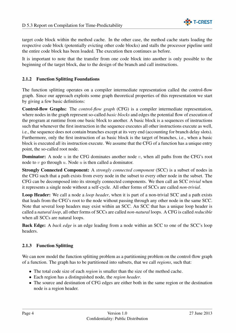
the region by adding BB4 without exceeding the size of the method cache. However, the region nowoccupies the entire method cache and cannot grow any further. Consequently, BB3 cannot be addedto the region. The basic block is thus marked as the region header of a second region. The last CFGnode visited by the algorithm is BB5. This node has two predecessors in the CFG, both of which areassigned to different regions, it is thus impossible to grow any of the two regions. BB5 thus becomesa region header of a third region.
Reducible CFGs: The approach from above cannot be applied to cyclic CFGs, since it cannot beassured for nodes within an SCC that all predecessors have been assigned to a region. However, inreducible CFGs the loop headers of all SCCs dominate the nodes within their respective SCCs. Thisproperty can be exploited to extend the approach from above:
Lemma 2. The loop header of an SCC has to be a region header unless all nodes in its SCC aremember of the same region.
We can now extend the approach from before by making case distinctions for loop headers duringthe traversal. However, before the traversal starts we remove all back edges from the CFG. Forregular nodes the traversal remains unchanged as before. For loop headers, we first check whetherthe predecessors of the loop header are all in the same region. If this is not the case the loop headerhas to become a region header and the traversal continues as usual. If all predecessors are withinthe same region we check whether the region can be grown. This time, however, we not only checkwhether adding the loop header alone results in a valid region. Instead, we check whether all thenodes in the loop header’s SCC can be added at once. If this is the case, all nodes of the SCC areadded to the region and skipped by when they are visited during the topological traversal.
Example 3. Considering again a method cache of size 4 and the reducible CFG of Figure 2, whereall basic blocks are assumed to be 1 word in size. The CFG is similar to that of the previous example,with the sole difference that a reducible loop exists containing the loop header BB1 and a regularblock BB3.
In order to apply our algorithm all back edges have to be removed. In this example the only backedge leads from BB3 to BB1. Its removal results in the same CFG as for the original example –where BB1 still remains a loop header for the algorithm.
The algorithm then processes the nodes of the CFG as before. First, the root node BB0 is visited,resulting in the creation of a new region of size 1. Then the loop header BB1 is visited. However,instead of simply growing the region by simply adding the node, the whole SCC associated with thenode has to be considered, i.e., both BB1 and BB3. Indeed, growing the region is possible and thetwo nodes are added to BB0’s region. The resulting region size is 3. Then, BB2 is visited and againadded to the region, which by now occupies the whole method cache. Consequently, a new regionsare formed when visiting BB4 and BB5.
Irreducible CFGs: The approach from above cannot be applied to irreducible CFGs since multipleloop headers may exist for one SCC. However, a lemma similar to Lemma 2 can be stated for loopheaders of non-natural loops.
Lemma 3. The loop headers of an SCC have to be region headers unless all nodes in the SCC aremember of the same region.
Page 6 Version 1.0Confidentiality: Public Distribution
27 June 2013
D 5.3 Report on Compilation for Time-Predictability
BB0
BB1 BB2
BB3 BB4
BB5
(a) Original CFG
BB0
BB1 BB2
BB3 BB4
BB5
(b) Regions of the CFG
Figure 2: A reducible control-flow graph and a possible partitioning into three regions.
The basic idea is to transform the CFG in such a way that all non-natural loops become naturalloops. Carrying this transformation out in a way that preserves the program’s original semantics,usually leads to an exponential increase in the size of the CFG [7] and would not be applicable in thecontext of the function splitting problem. We can, however, apply a simpler transformation that onlypreserves dominance [22]. Once the irreducible CFG has been transformed into a reducible one, weapply the algorithm from above. Note that the transformation is not applied to the program’s originalCFG but to a copy that is only used for the purpose of computing the partitioning into regions andthat is discarded afterward.
The CFG is iteratively transformed as follows:
1. The CFG is decomposed into its SCCs.
2. All back edges are removed from the graph.
3. For all non-natural SCCs, an artificial loop header is created and all edges leading to/from anyof the original loop headers are redirected to this new loop header.
4. This process is repeated until the CFG decomposes into trivial SCCs only.
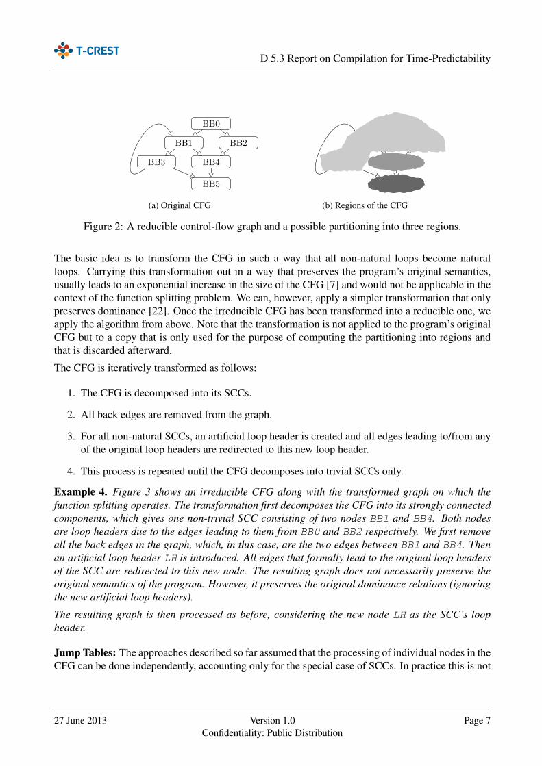
Example 4. Figure 3 shows an irreducible CFG along with the transformed graph on which thefunction splitting operates. The transformation first decomposes the CFG into its strongly connectedcomponents, which gives one non-trivial SCC consisting of two nodes BB1 and BB4. Both nodesare loop headers due to the edges leading to them from BB0 and BB2 respectively. We first removeall the back edges in the graph, which, in this case, are the two edges between BB1 and BB4. Thenan artificial loop header LH is introduced. All edges that formally lead to the original loop headersof the SCC are redirected to this new node. The resulting graph does not necessarily preserve theoriginal semantics of the program. However, it preserves the original dominance relations (ignoringthe new artificial loop headers).
The resulting graph is then processed as before, considering the new node LH as the SCC’s loopheader.
Jump Tables: The approaches described so far assumed that the processing of individual nodes in theCFG can be done independently, accounting only for the special case of SCCs. In practice this is not
27 June 2013 Version 1.0Confidentiality: Public Distribution
Page 7

D 5.3 Report on Compilation for Time-Predictability
BB0
BB1 BB2
BB3 BB4
BB5
(a) Original CFG
BB0
LH
BB1
BB2
BB3
BB4
BB5
(b) Transformed CFG
Figure 3: An irreducible control-flow graph and the transformed reducible graph used during functionsplitting.
always the case. The C switch statement, for instance, is often translated to an indirect branch usinga jump table. The jump table holds the addresses of the potential branch targets, which are indexedby the argument to the switch. The problem here is that the region partitioning is constrained bythe content of the branch table. We cannot decide independently for each target whether they shouldbe region headers of not, since this depends on a single instruction – the indirect branch. We can onlydecide whether all successors of the indirect branch become region headers or none.
We can again solve this problem by a simple transformation of the CFG that exploits the similaritybetween the constraints imposed by SCCs in the CFG and indirect branches. Both impose a choicebetween all or nothing. The idea here is to make the dependence between the nodes depending ona single branch instruction explicit by introducing artificial CFG edges that connects all the nodespotentially targeted by an indirect branch, effectively turning these nodes into an SCC. We can thenapply the strategy for reducible or irreducible graphs described before.
2.1.4 Future Directions
The function splitting algorithm presented above is a heuristic that may or may not provide optimalsolutions. It would be interesting to study the theoretical properties of the problem in more detailand investigate whether simple optimal algorithms can be found. As can be easily verified by theexamples given above, the ordering in which the nodes are visited has a large impact on the result-ing partitioning into regions. Improved strategies that determine good (or even the best) orderingsare needed, in particular, when the worst-case execution time should be optimised while splittingfunctions.
2.2 Stack Cache
A central feature of the Patmos processor is its stack cache [1], which allows to allocate the stackframe of functions partially or as a whole to a dedicated cache. The cache is organised as a circularbuffer that allows to allocate and free space in a first-in/first-out (FIFO) order. The hardware auto-matically manages spilling and filling data to/from main memory as needed. Our experiments [1, 24]show that a simple allocation strategy already leads to a considerable shift in the number and transfer
Page 8 Version 1.0Confidentiality: Public Distribution
27 June 2013
D 5.3 Report on Compilation for Time-Predictability
volume of data accesses. In some cases as much as 75% of the memory accesses are handled by thestack cache.
In addition to the allocation of data to the stack cache, the placement of instructions to manage theallocated space on the stack cache is relevant. The current model assumes three basic operationson the stack cache [10]: reserving space on the stack cache (sres), freeing space on the stackcache (sfree), and ensuring the availability of data in the stack cache (sens). These instructionsare generated automatically by the compiler, and thus are potential candidates for optimisations. Inaddition, bookkeeping instructions to save and restore the stack cache state before and after a threador task switch have been added to the instruction set of the Patmos processor. These are intendedfor system software, such as library and operating system code, and thus are not managed by thecompiler. We thus limit the remaining discussion on the three basic operations (sres, sfree, andsens).
The stack cache is mainly used to provide temporary memory space to hold the stack frames offunctions. The stack frame is mostly used to hold function-local variables and spill slots, whichare generated by the compiler’s register allocation phase. Since stack frames are associated with afunction, they are created during the execution of a program whenever a function is entered and aredestroyed whenever the execution returns from the function. The first action thus typically is to createthe function’s stack frame on the stack cache, while the last action is to free the function’s stack frameon the stack cache. While executing a function, it might well be that other functions are called andthat these functions similarly allocate space on the stack cache. The corresponding allocations mightoccupy a large portion of the stack cache and thus cause the stack frames of the calling function tobe spilled to main memory. When the execution now returns to the calling function, it has to beensured that the calling function’s stack frame is readily available in the stack cache. This is doneby placing ensure instructions (sens) after every call instruction, since it is not known staticallywhether executing a call causes spilling or not.
Definition 1. We denote by stack cache occupancy (or short occupancy) the amount of space allo-cated on the stack cache at the entry of a given function.
Considering the simple placement strategy of the stack management instructions described in theprevious paragraph, it becomes immediately apparent that the occupancy at the entry of a functiondepends on the calls that finally lead to the invocation of the function. This means that the occupancydepends on the nesting of the program’s functions and requires a context-sensitive program analysis.This is particularly relevant when the worst-case spilling behaviour of the reserve instructions of aprogram needs to be analysed.
Definition 2. We denote by stack cache displacement (or short displacement) the amount of dataspilled from the stack cache during the execution of a call.
In contrast to the stack cache occupancy, the displacement is independent of the nesting of functionsthat lead to the execution of the call instruction. It only depends on the nesting of the called functionsand thus does not require a context-sensitive program analysis.
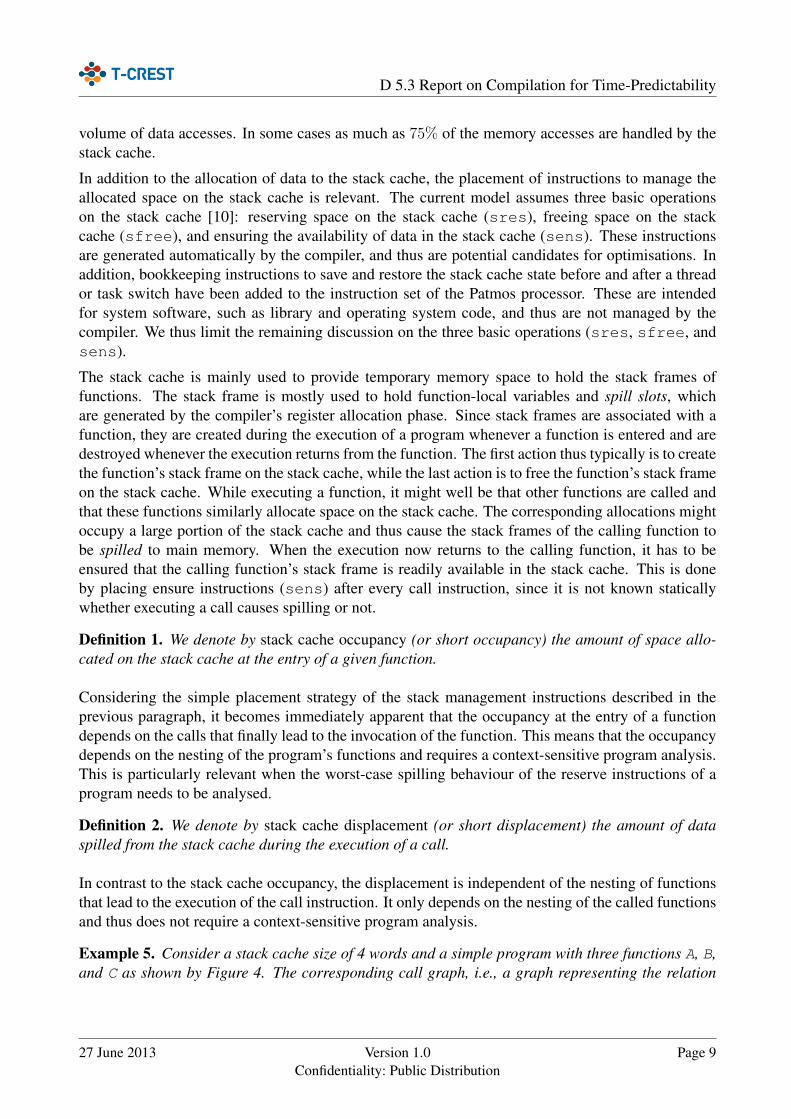
Example 5. Consider a stack cache size of 4 words and a simple program with three functions A, B,and C as shown by Figure 4. The corresponding call graph, i.e., a graph representing the relation
27 June 2013 Version 1.0Confidentiality: Public Distribution
Page 9

D 5.3 Report on Compilation for Time-Predictability
(1) func A() {(2) sres 2;(3) B();(4) sens 2;(5) C();(6) sens 2(7) sfree 2;(8) }
(a) Code of A
(1) func B() {(2) sres 3;(3) C();(4) sens 3(5) C();(6) sens 3(7) sfree 3;(8) }
(b) Code of B
(1) func C() {(2) sres 2;(3) sfree 2;(4) }
(c) Code of C
A()
B()
C()
(d) Call Graph
Figure 4: A simple program consisting of three functions and their calling relations.
between functions calling each other, is shown in Figure 4d. Function C is called from three different
contexts. The first context is A(3)−→B
(3)−→C, i.e., function A calls B on line 3, which in turn calls C on
line 3. The second context is similar A(3)−→B
(5)−→C and refers to call of B to C in line 5 instead of 3.
The last context is simply A(5)−→C.
The stack cache occupancy at the entry of C varies for all three context, and can be either 4, 3, or 2for the three context respectively. Note the difference between first context (calling C on line 3 of B)and the second (calling C on line 5). When the first call executes, a part of A’s stack data is alreadyevicted to the main memory and C’s reserve will evict all of A’s data as well as one word of B’s stackframe. When the execution reaches the second call all the data of A remains evicted, while all 3blocks of B where reloaded by the ensure instruction on line 4.
The displacement of C, on the other hand, is 2 for all three calling contexts.
2.2.1 Future Directions
When we take a closer look at the previous example (Ex. 5) we notice that not all ensure instructionsare needed for the correct execution of the program. The ensure on line 6 of function A, for instance,is useless, as we know that A’s stack frame is completely loaded back into the stack cache on line 4and remains present even during the execution of C.
We have developed an optimisation that eliminates ensure instructions, which cause most of theoverhead (code size, additional execution cycles) related to the stack cache. The key observationto perform such an optimisation is that the amount of data loaded by an ensure can be bounded byexamining the maximum stack cache displacement on the program paths between the ensure and itscorresponding reserve operation. We will describe this optimisation in deliverable D5.4.
The concepts of stack cache occupancy and stack cache displacement are highly related to the prob-lem of analysing the worst-case behaviour of the stack cache within a WCET analysis tool (such asaiT). We currently work on formulating an efficient analysis using these concepts that can be usedfor both improved compiler optimisations and better WCET analysis.
Page 10 Version 1.0Confidentiality: Public Distribution
27 June 2013

D 5.3 Report on Compilation for Time-Predictability
2.3 Data Scratchpad Memory (SPM)
A Scratchpad memory (SPM) provides a time-predictable way to store instructions and data [15]. AnSPM is a local memory that is closely coupled with a CPU.
SPMs are commonly found within microcontrollers, such as the Atmel AVR [3] or MicrochipPIC [16] series, where they may be the only form of RAM. They may also be found within largerCPUs such as Cell [12] where external RAM is also available.
An SPM implements constant-latency access to a small amount of private RAM, local to a singleCPU. This memory may be shared by all applications running on that CPU. Typical SPM sizes aresimilar to level 1 (L1) cache sizes, i.e. 2Kb to 16Kb [18].
2.3.1 Constant Latency
“Constant-latency” means that every access requires the same length of time to serve, regardless ofthe address [4]. This is unlike a cache, where the latency of each access depends on previously-usedaddresses. In some respects, SPMs are an ideal memory technology for embedded real-time systems,because any load or store operation targeting the SPM is guaranteed to have a constant executiontime [18]. This simplifies WCET analysis, because there is no need to analytically classify each loadoperation as “hit”, “miss”, “first miss” and so on [25]. All SPM accesses can be classifieed as “hits”.
Typical access latencies are a single CPU clock cycle for loads and stores, as SPMs are typicallysmall and placed near the CPU [25].
2.3.2 Accessing the SPM
In many systems, the SPM is mapped to a specific range of physical memory addresses. Loads andstores using these addresses are routed to the SPM. However, another option is to introduce typedloads and stores where a part of each instruction opcode indicates the type of memory to be used.This simplifies WCET analysis because it is easy to determine if an access will be routed to the SPM.Patmos uses typed loads and stores to distinguish between accesses that will be handled by the stackcache, by the data cache and by the SPM.
2.3.3 DMA Controller
Sometimes, an SPM is accompanied by a direct memory access (DMA) controller [28]. The purposeof this hardware device is to implement high-speed copy operations between the external memoryand the SPM. This is used to load the SPM with code and data as required, and to copy modifieddata back to the external memory. The same functionality is possible using software (e.g. memcpy)but the DMA controller is likely to be faster because it can take full advantage of bus and memorycapabilities such as burst transactions. Bursts allow more than one word to be sent together, reducingthe overhead of large transfers.
Within the Patmos architecture, the data SPM will be paired with a suitable DMA controller. TheDMA controller will operate as a co-processor, i.e. in parallel with the CPU. It will be controlled by
27 June 2013 Version 1.0Confidentiality: Public Distribution
Page 11

D 5.3 Report on Compilation for Time-Predictability
program instructions which initiate transfers between SPM and external memory, and which wait forthe current transfer to complete. The DMA controller will support a maximum of one transfer at atime, as multiple transfers are not useful in this context.
2.3.4 SPM as a Replacement for Cache
SPMs have disadvantages which have limited their uptake within larger embedded systems.
Each application is forced to take an active role in memory management, statically reserving partsof the SPM for variables [23]. Static allocation is practical for small microcontroller applications(thousands of lines of code) but not for larger applications (millions of lines of code) as an SPM isgenerally too small to store all of the variables required. In this case, some paging or overlay schemeis required to share the limited space between various parts of an application [8, 9].
The need for a paging scheme is a source of many practical problems. In order to make use of thetime-predictability advantage of an SPM, paging cannot be a reactive process that is triggered byloads and stores within the program. Instead, it must occur at predetermined points such as methodcalls and returns. Some of the major issues are:
1. Determining the best places to carry out paging (partitioning) is a complex optimisation prob-lem. It requires detailed information about the program’s use of data, and finding optimalsolutions may require exhaustive searches. The problem may be simplified by reducing thedegrees of available freedom, e.g. only partitioning the program at method call/return bound-aries, but this will mean that the SPM and memory bandwidth are not used to the greatest effect.Unfortunately, partitioning techniques do not scale well, or are limited to simplified programrepresentations such as trees [28].
2. It is necessary to carry out some form of analysis to be sure that data is only accessed when itis “paged in”, i.e. present in the SPM. This is a difficult problem if dynamic data structures areused [9].
3. Programs have to be modified to page themselves in and out of the SPM. This requires the useof self-modifying code when using an instruction SPM.
4. If multiple applications share the same areas of an SPM, the real-time operating system (RTOS)must be able to save and restore the SPM state used by each application [27].
Together, these issues limit the usefulness of an SPM as a cache replacement. The complex WCETanalysis required for a cache is replaced by equally complex analysis for the partitioning problem,and the WCET might be increased by the paging process and by inefficiencies in partitioning.
Therefore, the T-CREST project does not solely rely on an SPM. Patmos has a conventional datacache, a method cache, and a stack cache in addition to an SPM. The challenge is to use the SPMalongside these in order to reduce application WCETs.
Page 12 Version 1.0Confidentiality: Public Distribution
27 June 2013
D 5.3 Report on Compilation for Time-Predictability
2.3.5 SPM Alongside Cache
In the Patmos architecture, the main purpose of the SPM is to reduce pressure on the data cache. Themethod cache provides dedicated local storage for instructions (Section 2.1) while local variables arestored in the stack cache (Section 2.2). The remaining data is stored by default in the data cache, butmay be placed in the SPM instead.
The SPM can improve both predictability and performance when leveraged for common code pat-terns that interact suboptimally with a data cache. The general form of each pattern is an iterationthrough linear arrays in which some data is loaded or stored, a pattern typically found within matrixtransformations, filters, compression algorithms and sort/search algorithms [26]. In each case, thearrays are assumed to be larger than the SPM size. A simple example is:
for (i = 0; i < N; i++) {load(array[i]);
}
but more general forms are possible, for example where multiple arrays are used:
for (i = 0; i < N; i++) {load(array1[i]);load(array2[i]);load(array3[i]);
}
and where loads and stores are mixed:
for (i = 0; i < N; i++) {store(array2[i], load(array1[i]) + load(array2[i]));
}
and where the step is not constant:
for (i = j = 0; i < N; i++, j++) {load(array1[j]);if (load(array2[i])) j++;
}
Using a data cache, each of these patterns will execute quite efficiently. The data cache dividesmemory space into blocks, and once any part of a block is accessed, the whole block is loaded intocache. Therefore, an access to array1[0] is likely to fetch array1[1] into the cache, speedingsubsequent iterations until the end of the block is reached. WCET analysis can account for thisbehaviour by avoiding the assumption that all loads are misses. However, there is still one miss perblock.
An SPM and DMA controller can be used to handle the code patterns even more efficiently byavoiding this blocking. This is done by copying data using the DMA controller while the CPU is
27 June 2013 Version 1.0Confidentiality: Public Distribution
Page 13
D 5.3 Report on Compilation for Time-Predictability
running the code. If this is arranged correctly, the CPU never needs to wait for the DMA operationto complete, as data is always available on time.
Furthermore, the SPM handles store operations more efficiently. For time-predictability reasons, thedata cache has a write-through policy, meaning that each stored word is immediately committed toexternal memory. This is not an efficient use of memory bandwidth because the words are writtenone at a time. The combination of an SPM and a DMA controller allows multiple words to be copiedto the external memory in a burst.
Together, these benefits will (1) reduce the memory bandwidth required, because the memory bus isused more efficiently, and (2) reduce the WCET of the application, because blocking time is reducedor eliminated.
2.3.6 Modifying Programs to use SPM
The code patterns listed in section 2.3.5 are accelerated by buffering each load/store operation usingthe SPM. In this section, the buffering process is described for the following example:
for (i = 0; i < N; i++) {load(array[i]);
}
Assume that the SPM can contain up to 2M array elements, where 2M < N. Take two areas of SPMspace, each of size M, and label them A and B.
The CPU should process area A while area B is filled with data. Then the roles are exchanged. TheCPU processes area B while area A is filled. The example is rewritten as follows:
start DMA copy: array[0..M-1] -> Afor (i = 0; i < N; ) {
start DMA copy: array[i+M..i+2M-1] -> Bfor (j = 0; (j < M) && (i < N); j++, i++) {
load(A[i]);}start DMA copy: array[i+M..i+2M-1] -> Afor (j = 0; (j < M) && (i < N); j++, i++) {
load(B[i]);}
}
The DMA controller only processes one transfer at a time, so each start DMA operation waits forthe previous transfer to finish. Provided that each DMA copy takes less time than each inner forloop, the CPU will never be forced to wait.
There is a minor inefficiency in that some of the data copied into the SPM will not be used (upto 2M-1 elements at the end of the array). This may be avoided by introducing conditions for thestart DMA operations to bound copies at array[N-1]. These conditions are omitted for clarity.
Page 14 Version 1.0Confidentiality: Public Distribution
27 June 2013

D 5.3 Report on Compilation for Time-Predictability
The example generalises for all of the code patterns listed in section 2.3.5. If multiple arrays areinvolved, the SPM must be further subdivided. If store operations are involved, the DMA copies runin the opposite direction, i.e.:
start DMA copy: A -> array[i..i+M-1]
Arrays may be accessed by both load and store operations. In this case, DMA copies are required inboth directions. These are also required if the store operation does not write to every array element.Otherwise, any skipped elements become undefined when written to the external memory.
2.3.7 Limitations
The scheme described above has two important limitations, which apply irrespective of the codepattern that is used.
Firstly, the presence of store operations leads to the possibility of incorrect code behaviour if arraysoverlap in memory. If arrays overlap, multiple copies of a single array element might exist withinthe SPM, and a store operation will only update one copy. There are elaborate schemes to avoidthis aliasing problem [25], but they have not been shown to be practical. Ultimately, it must be theprogrammer’s responsibility to avoid the possibility of overlapping when using the SPM and DMAcontroller.
Secondly, after modifications are applied, the code pattern forms a critical section requiring dedicatedaccess to the SPM resource. It is possible to save and restore the SPM state across preemptions, thusavoiding the creation of a critical section, but another elaborate scheme is required to do this [27],again of limited practicality.
2.3.8 SPM Buffer API
The code pattern modifications could be applied by the compiler, acting on the intermediate repre-sentation of the application. However, this process would be directed by the programmer, specifyingthe arrays to be stored in the SPM. Without hints from the programmer, the compiler might allocateSPM space too eagerly, perhaps modifying loops where the SPM is not appropriate, e.g. because thearray is very small, or because arrays overlap. It might miss opportunities for the use of the SPM byfailing to recognise code patterns.
Given that this degree of programmer involvement is required in any case, the modifications maybe implemented using inlined C functions, with the advantage that no compiler modifications areneeded.
Programs are modified by including a header file ("buffer.h"). Inline functions are then calledto (1) initialise each buffer, (2) consume/produce elements, and (3) finalise operations on that buffer:
SPM_BFE_Buffer buf;spm_bfe_init(&buf, array, A, M);for (i = 0; i < N; i++) {
27 June 2013 Version 1.0Confidentiality: Public Distribution
Page 15

D 5.3 Report on Compilation for Time-Predictability
load(spm_bfe_consume(&buf));}spm_bfe_finish(&buf);
Each buffer is automatically managed by the spm_∗ functions. The programmer need only spec-ify the location A and the size M of the available SPM space, the source/destination array,and provide a handle (buf). Transfers from external memory are handled by functions namedspm_bfe_∗ (bfe = buffer from external memory). Transfers to external memory are handled byfunctions named spm_bte_∗ (buffer to external memory).
Within the T-CREST project, a proof-of-concept implementation of this API has already been com-pleted. The API has been used to implement an SPM version of the Merge Sort algorithm. MergeSort is an example of an external sort, meaning that it is suitable for sorting data that is too large to fitin memory. In this case, the unsorted data is too large to fit in the SPM, so it is fetched from externalmemory via the buffer API.
2.3.9 Address Space Attributes
Since Patmos uses typed loads to access the SPM, the compiler has to know statically for everymemory access which memory type will be accessed. Since in T-CREST the SPM is managed bythe programmer, it is the programmer’s task to tell the compiler about memory accesses to the SPM.We use the address_space attribute to mark pointers into the SPM. The newlib based libcimplementation for Patmos defines a _SPM macro that can be used to prefix the type of all pointersinto the SPM. This is in line with the specification for named address spaces in the Technical Reporton Embedded C [11].
Example 6. Figure 5 shows a sample program that uses the SPM on Patmos. It defines a structurespm_ptrs_t that contains three pointers to data structures in the SPM. The main function placesan instance of that structure at the beginning of the SPM and initializes it. Then the function createsa new data structure data in global memory using malloc and fills it with some data. Then thefunction uses the spm_copy_from_ext provided by the SPM API to transfer the data from globalmemory to the SPM, and then calls the custom spm_merge function, which merges two input listsinto a single output list directly on the SPM. Note that the first argument of the spm_merge functionis a pointer into the SPM and thus needs to be marked as such. Also note that the programmer onlyneeds to specify at the declaration of a pointer that it uses the SPM, not at every actual memoryaccess, as this is done by the compiler based on the type of the pointers.
The address space is part of the type of a pointer, therefore the compiler can check that pointers todifferent memories are not mixed. Otherwise this would lead to incorrect code, as the compiler wouldthen generate loads and stores to the main memory to access data on the SPM, or vice versa.
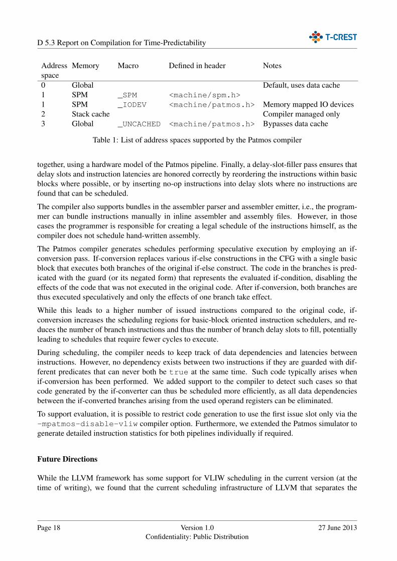
In addition to the SPM, accessing the global memory without data cache can also be controlled viaaddress spaces. IO mapped devices are also accessed with loads and stores to the SPM, but to supportfuture design changes the libc library defines a separate _IODEV macro for IO devices. Table 1gives an overview of the supported address spaces.
Page 16 Version 1.0Confidentiality: Public Distribution
27 June 2013

D 5.3 Report on Compilation for Time-Predictability
#include <machine/spm.h>
#define INPUT_ELEMS 10
typedef struct {_SPM int *input_A;_SPM int *input_B;_SPM int *output;
} spm_ptrs_t;
void spm_merge(_SPM spm_ptrs_t *ptrs, size_t size) {size_t a = 0, b = 0;_SPM int* input_A = ptrs->input_A, *input_B = ptrs->input_B;
// merge pre-sorted lists input_A and input_B into output listfor (size_t i = 0; i < 2*size; i++) {ptrs->output[i] = (input_A[a] < input_B[b]) ? input_A[a++] : input_B[b++];
}}
int main(int argc, char** argv) {_SPM spm_ptrs_t *ptrs = SPM_BASE;ptrs->input_A = (_SPM int*) SPM_BASE + sizeof(spm_ptrs_t);ptrs->input_B = (_SPM int*) SPM_BASE + sizeof(spm_ptrs_t) + INPUT_ELEMS*sizeof(int);ptrs->output = (_SPM int*) SPM_BASE + sizeof(spm_ptrs_t) + 2*INPUT_ELEMS*sizeof(int);
// produce some values into *dataint *data = (int*) malloc(2 * INPUT_ELEMS * sizeof(int) );int *tmp = data;for (int i = 0; i < INPUT_ELEMS; i++) *tmp++ = i * 2;for (int i = 0; i < INPUT_ELEMS; i++) *tmp++ = i * 3;
// copy data to SPM and call spm_mergespm_copy_from_ext(ptrs->input_A, data, INPUT_ELEMS*sizeof(int));spm_copy_from_ext(ptrs->input_B, data + INPUT_ELEMS, INPUT_ELEMS*sizeof(int));spm_merge(ptrs, INPUT_ELEMS);
return 0;}
Figure 5: A short example program demonstrating the use of SPM pointers
2.4 Code Generation for VLIW
Patmos employs two ALU function units to increase the instruction level parallelism (ILP). Patmosuses a Very Large Instruction Word (VLIW) architecture with no interlocking, where operations arestatically assigned to the function units. While this significantly reduces the complexity of a pipelineanalysis for the WCET analysis in contrast to dynamic instruction scheduling on an out-of-orderarchitecture, it now falls to the compiler to generate a static schedule that maximises the hardwareutilization. Since Patmos does not dynamically check for hazards between most instructions, thecompiler must also ensure that the instruction schedule respects the latencies of the individual in-structions, as well as the delay slots of control flow instructions and the limitations imposed by thehardware on which operations can be bundled to a single VLIW instruction.
We used the VLIW scheduling support provided by the LLVM 3.2 framework to implement schedul-ing for Patmos. A pre-register-allocation (pre-RA) scheduling pass orders instructions at machineinstruction level so that consecutive instructions honor the hardware restrictions for instruction bun-dles. A separate pass after register allocation decides on which instructions are actually bundled
27 June 2013 Version 1.0Confidentiality: Public Distribution
Page 17
D 5.3 Report on Compilation for Time-Predictability
Addressspace
Memory Macro Defined in header Notes
0 Global Default, uses data cache1 SPM _SPM <machine/spm.h>1 SPM _IODEV <machine/patmos.h> Memory mapped IO devices2 Stack cache Compiler managed only3 Global _UNCACHED <machine/patmos.h> Bypasses data cache
Table 1: List of address spaces supported by the Patmos compiler
together, using a hardware model of the Patmos pipeline. Finally, a delay-slot-filler pass ensures thatdelay slots and instruction latencies are honored correctly by reordering the instructions within basicblocks where possible, or by inserting no-op instructions into delay slots where no instructions arefound that can be scheduled.
The compiler also supports bundles in the assembler parser and assembler emitter, i.e., the program-mer can bundle instructions manually in inline assembler and assembly files. However, in thosecases the programmer is responsible for creating a legal schedule of the instructions himself, as thecompiler does not schedule hand-written assembly.
The Patmos compiler generates schedules performing speculative execution by employing an if-conversion pass. If-conversion replaces various if-else constructions in the CFG with a single basicblock that executes both branches of the original if-else construct. The code in the branches is pred-icated with the guard (or its negated form) that represents the evaluated if-condition, disabling theeffects of the code that was not executed in the original code. After if-conversion, both branches arethus executed speculatively and only the effects of one branch take effect.
While this leads to a higher number of issued instructions compared to the original code, if-conversion increases the scheduling regions for basic-block oriented instruction schedulers, and re-duces the number of branch instructions and thus the number of branch delay slots to fill, potentiallyleading to schedules that require fewer cycles to execute.
During scheduling, the compiler needs to keep track of data dependencies and latencies betweeninstructions. However, no dependency exists between two instructions if they are guarded with dif-ferent predicates that can never both be true at the same time. Such code typically arises whenif-conversion has been performed. We added support to the compiler to detect such cases so thatcode generated by the if-converter can thus be scheduled more efficiently, as all data dependenciesbetween the if-converted branches arising from the used operand registers can be eliminated.
To support evaluation, it is possible to restrict code generation to use the first issue slot only via the-mpatmos-disable-vliw compiler option. Furthermore, we extended the Patmos simulator togenerate detailed instruction statistics for both pipelines individually if required.
Future Directions
While the LLVM framework has some support for VLIW scheduling in the current version (at thetime of writing), we found that the current scheduling infrastructure of LLVM that separates the
Page 18 Version 1.0Confidentiality: Public Distribution
27 June 2013
D 5.3 Report on Compilation for Time-Predictability
instruction scheduling into several passes leads to sub-optimal schedules and to scheduler implemen-tations that are very hard to maintain. We are therefore currently implementing a new scheduler thatintegrates delay-slot filling, creation of instruction bundles and latency driven scheduling into a singlescheduler pass that uses a standard bottom-up list scheduling strategy.
This new scheduler will not only be able to create better instruction schedules, but also enables usto implement more advanced and new scheduling strategies. We plan to integrate the if-converterand the single-path pass with the instruction scheduler to improve the quality of the generated sched-ules. Furthermore we plan to investigate into global code scheduling strategies (across basic blockboundaries) that optimise the instruction schedule for a low WCET.
3 Single-Path Code Generation
Given a piece of code, we can identify three factors that determine its actual execution time:
• The hardware on which the code is to run• The sequence of instructions• The context in which the code is executed (execution history, input values)
In the hardware domain, the architecture of the Patmos processor provides means to make the pro-cessor timing independent of the execution context. As for the software, we devise a code-generationstrategy that ensures that the sequence of instructions executed during a program execution are in-sensitive to the values of input variables.
By making the execution time of a piece of code independent from input values, we address oneaspect of time-predictability: stability. Following the notions defined in D1.1, stability is a measurefor the variability of the system timing behaviour. Regarding code execution times [21, 13], a stablesystem exposes a minimal difference between worst-case and best-case execution time. Hence, onecould make reasonable predictions for the execution time of every execution by the knowledge of asingle execution.
The idea behind the single-path transformation is to generate code that follows the same executiontrace for whatever input data is received. The single-path transformation is a code generation strategythat extends the idea of if-conversion [2] to transform branching code into code with a single trace.Input-data dependent branching code is replaced by code that uses predicated instructions to controlthe semantics of the executed code. Loops are treated in a similar way: Loops with input-datadependent iteration conditions are transformed into loops for which the number of iterations is knownat compile time, again using predicated instructions to preserve program semantics.
While the single-path conversion was described by Puschner et al. [20] on a high-level programrepresentation, this document describes the transformation on the language-independent CFG leveland its implementation targeting the Patmos processor ISA, which has been integrated into the LLVMcompiler backend for Patmos.
27 June 2013 Version 1.0Confidentiality: Public Distribution
Page 19
D 5.3 Report on Compilation for Time-Predictability
3.1 Overview
The single-path transformation is performed late in the code generation process: after register allo-cation, prologue-epilogue insertion, and control-flow optimisations, and before the final schedulingpass. At this stage, the transformation pass operates on the control-flow graph of a machine function,where the order of the basic blocks in the memory is already defined.
The LLVM framework provides only minimal generic support for predicated instructions. Mostimportant passes, like register allocation and instruction scheduling, are unaware of predication. Per-forming the single-path conversion at that late point in the code generation phase seems adequate asthe control-flow graph remains unmodified subsequently and the pseudo instructions introduced byregister allocation (e.g. register copies) are already expanded.
As a consequence, care must be taken that temporary registers and stack slots required as additionalstorage for predicate registers and newly introduced loop counters are reserved and available duringthe transformation, and this has to be ensured before register allocation (reserve registers) resp. beforeprologue-epilogue insertion (reserve stack slots). In the following, we describe the main transforma-tion pass and mention steps that required preparation in an earlier phase explicitly.
3.2 Control Dependence Analysis
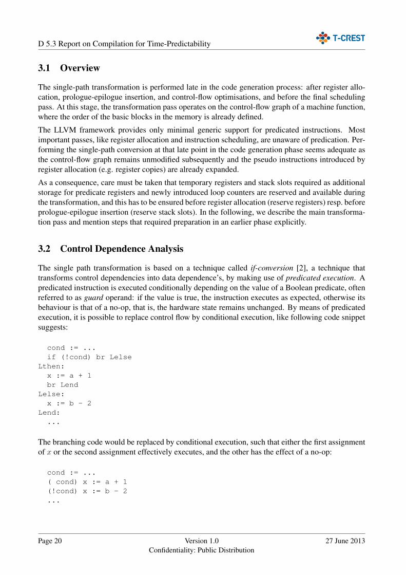
The single path transformation is based on a technique called if-conversion [2], a technique thattransforms control dependencies into data dependence’s, by making use of predicated execution. Apredicated instruction is executed conditionally depending on the value of a Boolean predicate, oftenreferred to as guard operand: if the value is true, the instruction executes as expected, otherwise itsbehaviour is that of a no-op, that is, the hardware state remains unchanged. By means of predicatedexecution, it is possible to replace control flow by conditional execution, like following code snippetsuggests:
cond := ...if (!cond) br Lelse
Lthen:x := a + 1br Lend
Lelse:x := b - 2
Lend:...
The branching code would be replaced by conditional execution, such that either the first assignmentof x or the second assignment effectively executes, and the other has the effect of a no-op:
cond := ...( cond) x := a + 1(!cond) x := b - 2...
Page 20 Version 1.0Confidentiality: Public Distribution
27 June 2013
D 5.3 Report on Compilation for Time-Predictability
The CFG allowing two possible execution paths, each containing a different assignment of x, istransformed to a CFG with a linear sequence of instructions containing both assignments of x, whereonly one of the two assignments is enabled by the guard.
The single-path transformation extends this conversion to whole functions (and programs). Ourtransformation algorithm is based on the RK algorithm [17], which converts the CFG of an innermostloop to a linear sequence of predicated basic blocks.
A basic concept of this algorithm is the concept of control dependence. Informally, if the branchat the end of basic block BBX determines whether basic block BBY is executed, BBY is controldependent on that branch.
Given a CFG G = 〈V,E〉, the control dependence function maps basic blocks V to control depen-dencies C,
CD : V → 2C
such that for any block v ∈ V , CD(v) is the set of its control dependencies. Each control dependencec ∈ C is denoted as ±w with w ∈ V and +w denoting the true edge (i.e., the edge taken when thebranch condition at the end of block w evaluates to true) leaving block w and −w for the false edge:
CD(v) ≡ {±w ∈ C | v is control dependent on ±w}
Block v is executed if and only if the branch condition or its negation corresponding to one controldependence c ∈ CD(v) is satisfied. The control dependence function induces a partitioning on thenodes of the CFG into equivalence classes:
v ∼ w ⇔ CD(v) = CD(w)
Semantically, if v ∼ w, then on every execution path v is executed if and only if w is executed. Toeach of the equivalence classes a unique predicate is assigned, and the set of predicates is denoted asP .
Given the control dependence function CD, the set of vertices V (basic blocks) of a CFG, and theset of predicates P , the RK algorithm computes two functions R and K that determine (1) whichpredicate is assigned to each basic block, and (2) where each of the predicates is defined.
Function R : V → P assigns to each basic block v ∈ V a predicate p ∈ P , such that v is enabledif and only if p is true. p is true when a control dependence c ∈ CD(v) is satisfied. K : P →range(CD) maps each p ∈ P to the corresponding set of control dependencies.
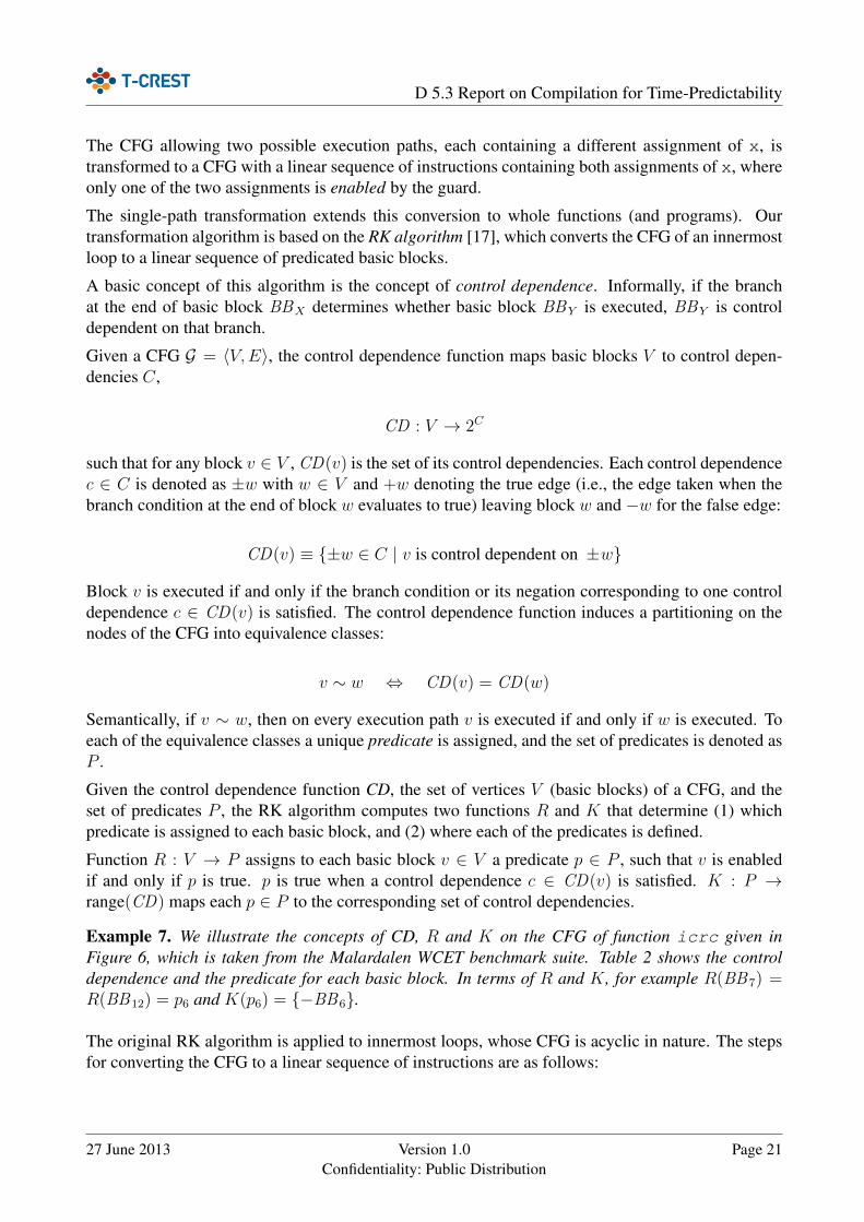
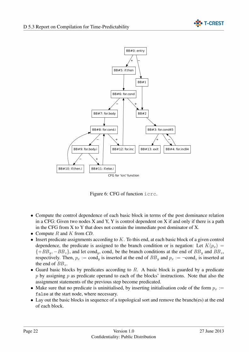
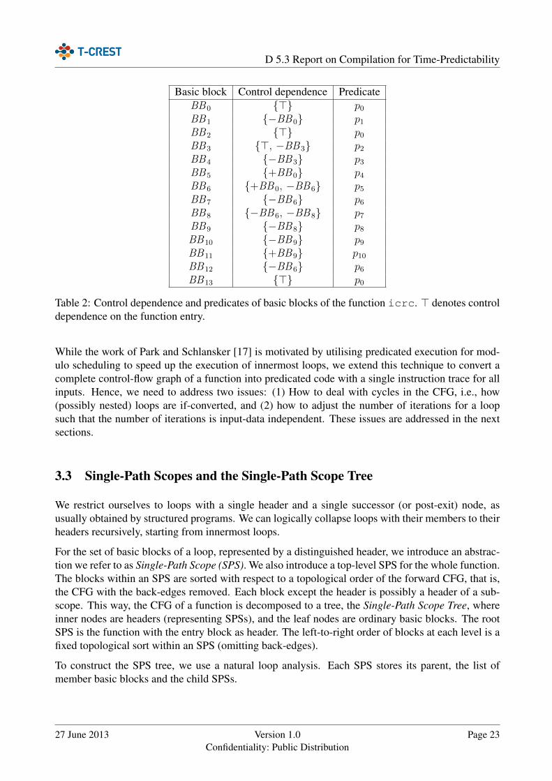
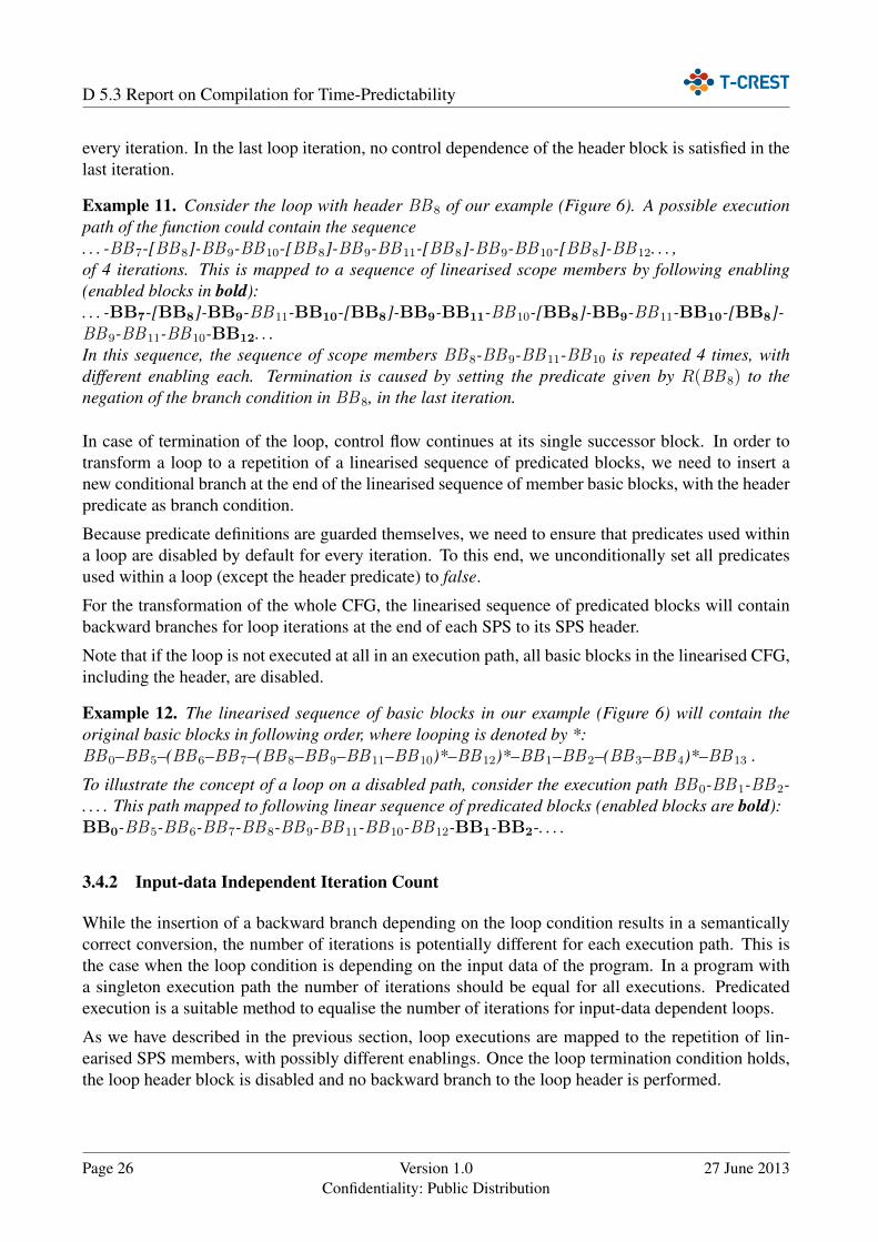
Example 7. We illustrate the concepts of CD, R and K on the CFG of function icrc given inFigure 6, which is taken from the Malardalen WCET benchmark suite. Table 2 shows the controldependence and the predicate for each basic block. In terms of R and K, for example R(BB7) =R(BB12) = p6 and K(p6) = {−BB6}.
The original RK algorithm is applied to innermost loops, whose CFG is acyclic in nature. The stepsfor converting the CFG to a linear sequence of instructions are as follows:
27 June 2013 Version 1.0Confidentiality: Public Distribution
Page 21
D 5.3 Report on Compilation for Time-Predictability
CFG for 'icrc' function
BB#0: entry
BB#1
−
BB#5: if.then
+
BB#2
BB#6: for.cond
BB#3: for.cond45
BB#4: for.inc84
−
BB#13: exit
+
+
BB#7: for.body
−
BB#8: for.cond.i
BB#9: for.body.i
−
BB#12: for.inc
+
BB#10: if.then.i
−
BB#11: if.else.i
+
Figure 6: CFG of function icrc.
• Compute the control dependence of each basic block in terms of the post dominance relationin a CFG: Given two nodes X and Y, Y is control dependent on X if and only if there is a pathin the CFG from X to Y that does not contain the immediate post dominator of X.• Compute R and K from CD.• Insert predicate assignments according to K. To this end, at each basic block of a given control
dependence, the predicate is assigned to the branch condition or is negation: Let K(px) ={+BBy,−BB z}, and let condy, condz be the branch conditions at the end of BBy and BB z,respectively. Then, px := condy is inserted at the end of BBy and px := ¬condz is inserted atthe end of BB z.• Guard basic blocks by predicates according to R. A basic block is guarded by a predicatep by assigning p as predicate operand to each of the blocks’ instructions. Note that also theassignment statements of the previous step become predicated.• Make sure that no predicate is uninitialised, by inserting initialisation code of the form px :=false at the start node, where necessary.• Lay out the basic blocks in sequence of a topological sort and remove the branch(es) at the end
of each block.
Page 22 Version 1.0Confidentiality: Public Distribution
27 June 2013
D 5.3 Report on Compilation for Time-Predictability
Basic block Control dependence PredicateBB0 {>} p0BB1 {−BB0} p1BB2 {>} p0BB3 {>, −BB3} p2BB4 {−BB3} p3BB5 {+BB0} p4BB6 {+BB0, −BB6} p5BB7 {−BB6} p6BB8 {−BB6, −BB8} p7BB9 {−BB8} p8BB10 {−BB9} p9BB11 {+BB9} p10BB12 {−BB6} p6BB13 {>} p0
Table 2: Control dependence and predicates of basic blocks of the function icrc. > denotes controldependence on the function entry.
While the work of Park and Schlansker [17] is motivated by utilising predicated execution for mod-ulo scheduling to speed up the execution of innermost loops, we extend this technique to convert acomplete control-flow graph of a function into predicated code with a single instruction trace for allinputs. Hence, we need to address two issues: (1) How to deal with cycles in the CFG, i.e., how(possibly nested) loops are if-converted, and (2) how to adjust the number of iterations for a loopsuch that the number of iterations is input-data independent. These issues are addressed in the nextsections.
3.3 Single-Path Scopes and the Single-Path Scope Tree
We restrict ourselves to loops with a single header and a single successor (or post-exit) node, asusually obtained by structured programs. We can logically collapse loops with their members to theirheaders recursively, starting from innermost loops.
For the set of basic blocks of a loop, represented by a distinguished header, we introduce an abstrac-tion we refer to as Single-Path Scope (SPS). We also introduce a top-level SPS for the whole function.The blocks within an SPS are sorted with respect to a topological order of the forward CFG, that is,the CFG with the back-edges removed. Each block except the header is possibly a header of a sub-scope. This way, the CFG of a function is decomposed to a tree, the Single-Path Scope Tree, whereinner nodes are headers (representing SPSs), and the leaf nodes are ordinary basic blocks. The rootSPS is the function with the entry block as header. The left-to-right order of blocks at each level is afixed topological sort within an SPS (omitting back-edges).
To construct the SPS tree, we use a natural loop analysis. Each SPS stores its parent, the list ofmember basic blocks and the child SPSs.
27 June 2013 Version 1.0Confidentiality: Public Distribution
Page 23
D 5.3 Report on Compilation for Time-Predictability
BB#0
BB#5 BB#6 BB#1 BB#2 BB#3 BB#13
BB#7 BB#8 BB#12 BB#4
BB#9 BB#11 BB#10
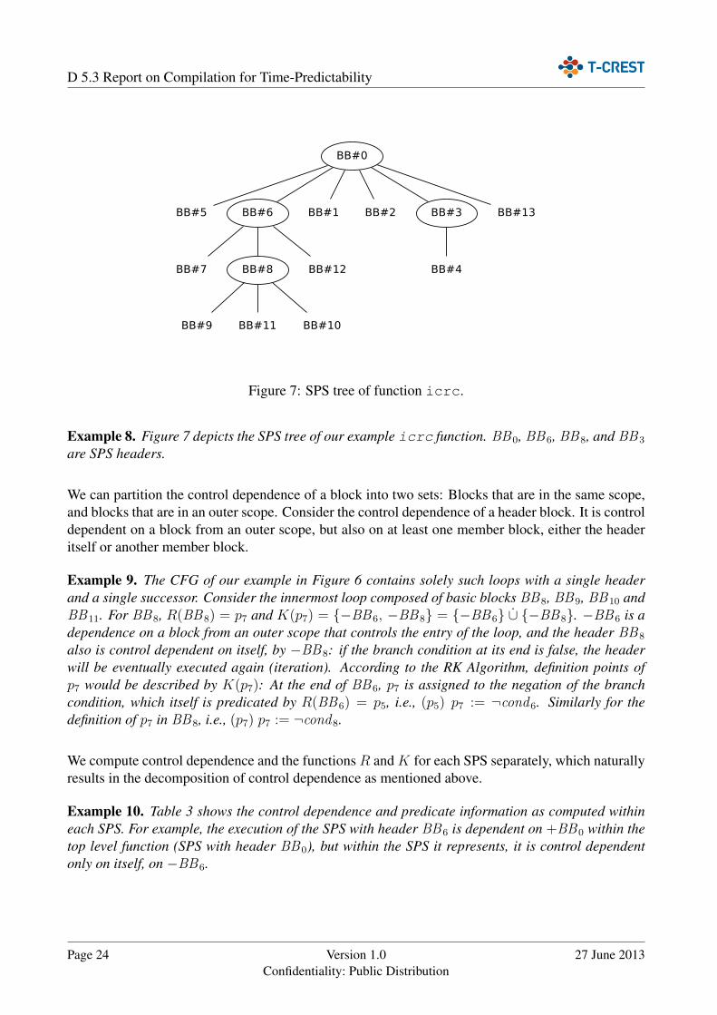
Figure 7: SPS tree of function icrc.
Example 8. Figure 7 depicts the SPS tree of our example icrc function. BB0, BB6, BB8, and BB3
are SPS headers.
We can partition the control dependence of a block into two sets: Blocks that are in the same scope,and blocks that are in an outer scope. Consider the control dependence of a header block. It is controldependent on a block from an outer scope, but also on at least one member block, either the headeritself or another member block.
Example 9. The CFG of our example in Figure 6 contains solely such loops with a single headerand a single successor. Consider the innermost loop composed of basic blocks BB8, BB9, BB10 andBB11. For BB8, R(BB8) = p7 and K(p7) = {−BB6, −BB8} = {−BB6} ∪̇ {−BB8}. −BB6 is adependence on a block from an outer scope that controls the entry of the loop, and the header BB8
also is control dependent on itself, by −BB8: if the branch condition at its end is false, the headerwill be eventually executed again (iteration). According to the RK Algorithm, definition points ofp7 would be described by K(p7): At the end of BB6, p7 is assigned to the negation of the branchcondition, which itself is predicated by R(BB6) = p5, i.e., (p5) p7 := ¬cond6. Similarly for thedefinition of p7 in BB8, i.e., (p7) p7 := ¬cond8.
We compute control dependence and the functions R and K for each SPS separately, which naturallyresults in the decomposition of control dependence as mentioned above.
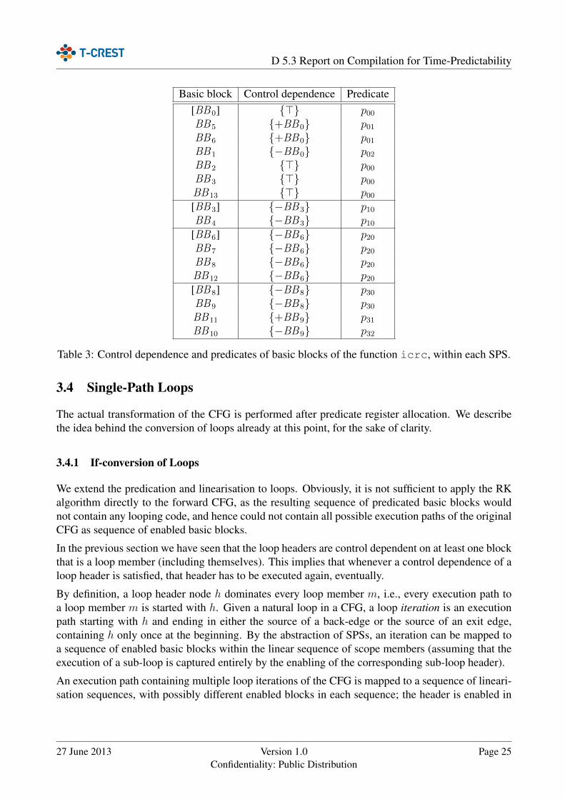
Example 10. Table 3 shows the control dependence and predicate information as computed withineach SPS. For example, the execution of the SPS with header BB6 is dependent on +BB0 within thetop level function (SPS with header BB0), but within the SPS it represents, it is control dependentonly on itself, on −BB6.
Page 24 Version 1.0Confidentiality: Public Distribution
27 June 2013
D 5.3 Report on Compilation for Time-Predictability
Basic block Control dependence Predicate[BB0] {>} p00BB5 {+BB0} p01BB6 {+BB0} p01BB1 {−BB0} p02BB2 {>} p00BB3 {>} p00BB13 {>} p00[BB3] {−BB3} p10BB4 {−BB3} p10
[BB6] {−BB6} p20BB7 {−BB6} p20BB8 {−BB6} p20BB12 {−BB6} p20[BB8] {−BB8} p30BB9 {−BB8} p30BB11 {+BB9} p31BB10 {−BB9} p32
Table 3: Control dependence and predicates of basic blocks of the function icrc, within each SPS.
3.4 Single-Path Loops
The actual transformation of the CFG is performed after predicate register allocation. We describethe idea behind the conversion of loops already at this point, for the sake of clarity.
3.4.1 If-conversion of Loops
We extend the predication and linearisation to loops. Obviously, it is not sufficient to apply the RKalgorithm directly to the forward CFG, as the resulting sequence of predicated basic blocks wouldnot contain any looping code, and hence could not contain all possible execution paths of the originalCFG as sequence of enabled basic blocks.
In the previous section we have seen that the loop headers are control dependent on at least one blockthat is a loop member (including themselves). This implies that whenever a control dependence of aloop header is satisfied, that header has to be executed again, eventually.
By definition, a loop header node h dominates every loop member m, i.e., every execution path toa loop member m is started with h. Given a natural loop in a CFG, a loop iteration is an executionpath starting with h and ending in either the source of a back-edge or the source of an exit edge,containing h only once at the beginning. By the abstraction of SPSs, an iteration can be mapped toa sequence of enabled basic blocks within the linear sequence of scope members (assuming that theexecution of a sub-loop is captured entirely by the enabling of the corresponding sub-loop header).
An execution path containing multiple loop iterations of the CFG is mapped to a sequence of lineari-sation sequences, with possibly different enabled blocks in each sequence; the header is enabled in
27 June 2013 Version 1.0Confidentiality: Public Distribution
Page 25
D 5.3 Report on Compilation for Time-Predictability
every iteration. In the last loop iteration, no control dependence of the header block is satisfied in thelast iteration.
Example 11. Consider the loop with header BB8 of our example (Figure 6). A possible executionpath of the function could contain the sequence. . . -BB7-[BB8]-BB9-BB10-[BB8]-BB9-BB11-[BB8]-BB9-BB10-[BB8]-BB12. . . ,of 4 iterations. This is mapped to a sequence of linearised scope members by following enabling(enabled blocks in bold):. . . -BB7-[BB8]-BB9-BB11-BB10-[BB8]-BB9-BB11-BB10-[BB8]-BB9-BB11-BB10-[BB8]-BB9-BB11-BB10-BB12. . .In this sequence, the sequence of scope members BB8-BB9-BB11-BB10 is repeated 4 times, withdifferent enabling each. Termination is caused by setting the predicate given by R(BB8) to thenegation of the branch condition in BB8, in the last iteration.
In case of termination of the loop, control flow continues at its single successor block. In order totransform a loop to a repetition of a linearised sequence of predicated blocks, we need to insert anew conditional branch at the end of the linearised sequence of member basic blocks, with the headerpredicate as branch condition.
Because predicate definitions are guarded themselves, we need to ensure that predicates used withina loop are disabled by default for every iteration. To this end, we unconditionally set all predicatesused within a loop (except the header predicate) to false.
For the transformation of the whole CFG, the linearised sequence of predicated blocks will containbackward branches for loop iterations at the end of each SPS to its SPS header.
Note that if the loop is not executed at all in an execution path, all basic blocks in the linearised CFG,including the header, are disabled.
Example 12. The linearised sequence of basic blocks in our example (Figure 6) will contain theoriginal basic blocks in following order, where looping is denoted by *:BB0–BB5–(BB6–BB7–(BB8–BB9–BB11–BB10)*–BB12)*–BB1–BB2–(BB3–BB4)*–BB13 .
To illustrate the concept of a loop on a disabled path, consider the execution path BB0-BB1-BB2-. . . . This path mapped to following linear sequence of predicated blocks (enabled blocks are bold):BB0-BB5-BB6-BB7-BB8-BB9-BB11-BB10-BB12-BB1-BB2-. . . .
3.4.2 Input-data Independent Iteration Count
While the insertion of a backward branch depending on the loop condition results in a semanticallycorrect conversion, the number of iterations is potentially different for each execution path. This isthe case when the loop condition is depending on the input data of the program. In a program witha singleton execution path the number of iterations should be equal for all executions. Predicatedexecution is a suitable method to equalise the number of iterations for input-data dependent loops.
As we have described in the previous section, loop executions are mapped to the repetition of lin-earised SPS members, with possibly different enablings. Once the loop termination condition holds,the loop header block is disabled and no backward branch to the loop header is performed.
Page 26 Version 1.0Confidentiality: Public Distribution
27 June 2013
D 5.3 Report on Compilation for Time-Predictability
Also, if a loop is on a disabled path, the header is disabled initially. As a consequence, the sequenceof loop members is executed without doing any actual computation, as all loop members remaindisabled.
Definition 3. A disabled iteration is the execution of the linearised sequence of predicated loopmember blocks, in which all blocks are disabled.
Observation 1. By appending disabled iterations to any execution of a loop, the program semanticsis not altered.
As we need to know the maximum number of iterations for each loop in a real-time program, wecan use this information to equalise the number of loop iterations by means of disabled iterations.Instead of introducing a backward branch that is conditional on the header predicate, we introduce aconditional branch that is conditional on an iteration counter.
Before entering the loop, we load the maximum number of iterations for that loop into that counter,and at the end of the linearised member sequence we decrement the counter by one. If the counter isgreater than zero, we branch back to the loop header.
This way, every execution of the loop will have the same number of iterations, of which a suffixpossibly consists of disabled iterations.
3.5 Predicate Register Allocation
Computing the predicate information separately for each SPS is also convenient for predicate registerallocation. Based on the SPS tree of a function including decomposed control dependence informa-tion, the predicates are assigned to physical predicate registers. First, the set of available predicateregisters is determined, which is the set of all writable predicate registers excluding the predicateregisters used in the machine function. To ensure availability of predicate registers after the gen-eral register allocation passes, two of them are reserved for machine functions that are converted tosingle-path code.
A possible predicate register assignment is computed locally for each SPS. To this end, livenessinformation is computed for each predicate, and using a simple scan over the sequence of basicblocks, predicate definitions are either assigned to physical registers or locations on the stack, basedon the number of available registers. Predicate definitions can be written directly to stack locations,whereas uses must be in a register as they appear as predicate operands in machine instructions. Ateach use, if no physical register is available, one must be made available by spilling its contents to astack location. The register is chosen based on a furthest-next-use policy.
The motivation of performing allocation separately for SPSs stems from the structure of controldependencies. On one hand, predicates that are live at the entry of a header node are also live at theexit, with the possible exception of the predicate of the header node itself. On the other hand, livenessof predicates defined in a loop will not extend beyond the scope of the loop. Therefore, at entering aloop, the predicate of a sub-loop header is copied to a new location, such that the original predicateis preserved.
27 June 2013 Version 1.0Confidentiality: Public Distribution
Page 27
D 5.3 Report on Compilation for Time-Predictability
SPS No. of locations Assigned physical registersBB0 2 p01 7→ p2, p02 7→ p3
BB3 1 p10 7→ p4
BB6 1 p20 7→ p2
BB8 3 p30 7→ p3, p31 7→ p4, p32 7→ p5
Table 4: Register assignment in SPSs with 5 available physical registers (p2-p6), cf. Table 3. Notethat no writable physical register is required for the control dependence on the function entry (>), asp0 is used for this purpose (p00 7→ p0).
Furthermore, Patmos features the possibility to store the predicate register file as a whole by copyingthe special purpose register s0. We employ the strategy to store the predicate register file beforeentering a loop, and restoring it upon leaving it. For this purpose, for each loop nesting level a slot ofone byte is reserved on the stack cache.
To minimise the number of stores and restores of the predicate register file, we devised a scheme thatavoids unnecessary stores and restores around deeper nested loops, in case there are enough availablephysical registers for the loop. To this end, the number of required physical locations is added andpropagated up the SPS tree through a post-order traversal.
Definition 4. Let N be an SPS, and N.num be the number of locations required in N. Then, thecumulative number of locations N.cum is defined as
N.cum = N.num+ maxC ∈ children(N)
C.cum
Given the attributes N.num and N.cum for each SPS N, we can determine whether storing andrestoring of the predicate register file (PRF) in s0 can be omitted upon entry and exit respectively, ofa given SPS.
Lemma 4. Let N be an SPS, P its parent SPS and |Pavail| the number of available predicate registers.Then, storing/restoring of the PRF at N can be omitted if
P.num+ N.cum ≤ |Pavail|
Example 13. Figure 8 shows the SPS tree with the computed attributes. For BB3 and BB8, thecondition is fulfilled to avoid a store/restore of s0 around them. Table 4 depicts a resulting registerassignment. In this example, no stack location is required.
3.6 Linearisation of the Control-Flow Graph
After computing predicate assignment information, the actual code transformation step is performed.
First, for each SPS, all basic blocks are guarded by predicating the instructions according to theregister allocation information. Second, predicate definition instructions are inserted.
Page 28 Version 1.0Confidentiality: Public Distribution
27 June 2013

D 5.3 Report on Compilation for Time-Predictability
[BB#0] num = 2cum = 6
[BB#6] num = 1cum = 4
[BB#3] num = 1cum = 1
[BB#8] num = 3cum = 3
Figure 8: SPS tree headers of function icrc, annotated by the attributes of the required number oflocations, and the cumulative number of locations. The shaded nodes do not require store/restore ofs0 around them.
Next, the CFG is linearised by a pre-order traversal of the SPS tree. The original branch instructionsare removed and the successors of the basic blocks are updated accordingly. Whenever enteringa loop, a basic block is inserted, which contains code to store the predicate register file, to copythe header predicate, and to load a loop bound if this information is available. Similarly, whenevergoing back to a parent node, two basic blocks are inserted: one that contains the backward branch tothe loop header, and one after the branch, which restores the PRF. Depending whether loop boundinformation is available, the loop counter is loaded, decremented, compared against zero, and thecomparison result is used as branch condition. If no loop bound information is available, the headerpredicate is used as branch condition.
As a finalising step, consecutive basic blocks are merged where possible. This provides the subse-quent scheduling pass with larger basic blocks.
Example 14. Figure 9 depicts the CFG of the icrc function after the linearisation step. Basicblocks BB14–BB20 are newly introduced blocks around SPSs. Header predicates are copied at loopentries (cf. Table 3): p20 ← p01 in BB14, p30 ← p20 in BB15, and p10 ← p00 in BB19.Note how the shape of loops has been transformed from while-style to repeat-until-style, as the se-quence of blocks is visited at least once. Also, the alternatives at BB0 → BB1/BB5 and BB9 →BB10/BB11 have been eliminated.The CFG after the merging step is shown in Figure 10.
27 June 2013 Version 1.0Confidentiality: Public Distribution
Page 29
D 5.3 Report on Compilation for Time-Predictability
3.7 Future Directions
At this development stage, the single-path code generator is able to convert selected functions. Wewill extend the functionality to operate interprocedurally, such that all functions reachable from anentry function are also converted.
Although the single-path conversion is able to generate code for loops with a fixed iteration number,the backend lacks support to obtain this information down from higher-level program representations.Efforts in this direction are made to also pass more general flow constraints from bitcode to machine-code.
To optimise the single-path conversion, we will employ a sophisticated input-data dependence anal-ysis to avoid unnecessary transformation of input-data independent control flow.
An obstacle towards completely stable execution times is the access of external main memory. Tofurther improve stability, we plan to make use of the data scratchpad memory (cf. Section 2.3), byrestricting memory access to local memories within a task as much as possible.
Page 30 Version 1.0Confidentiality: Public Distribution
27 June 2013
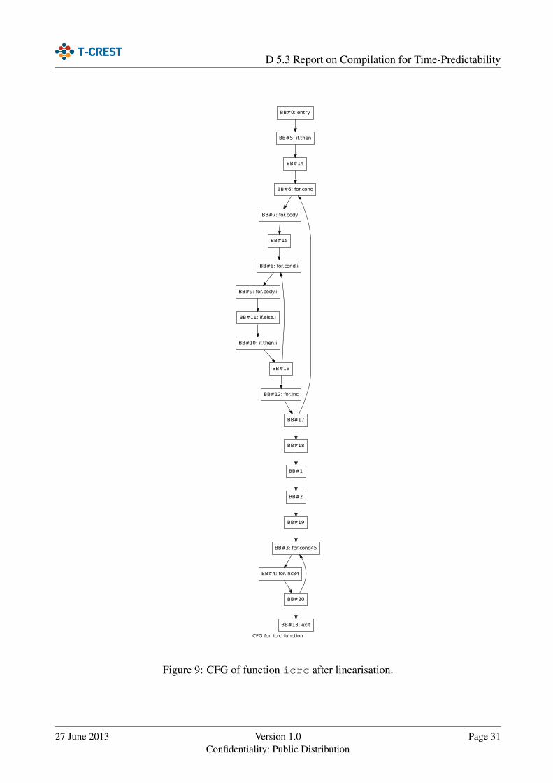
D 5.3 Report on Compilation for Time-Predictability
CFG for 'icrc' function
BB#0: entry
BB#5: if.then
BB#14
BB#6: for.cond
BB#7: for.body
BB#15
BB#8: for.cond.i
BB#9: for.body.i
BB#11: if.else.i
BB#10: if.then.i
BB#16
BB#12: for.inc
BB#17
BB#18
BB#1
BB#2
BB#19
BB#3: for.cond45
BB#4: for.inc84
BB#20
BB#13: exit
Figure 9: CFG of function icrc after linearisation.
27 June 2013 Version 1.0Confidentiality: Public Distribution
Page 31

D 5.3 Report on Compilation for Time-Predictability
CFG for 'icrc' function
BB#0: entry
BB#6: for.cond
BB#8: for.cond.i
BB#12: for.inc
BB#18
BB#3: for.cond45
BB#13: exit
Figure 10: CFG of function icrc after merging basic blocks.
Page 32 Version 1.0Confidentiality: Public Distribution
27 June 2013
D 5.3 Report on Compilation for Time-Predictability
4 Integration of Compiler and WCET Analysis
Bernat and Holsti [5] identify four categories of features the compiler should provide to supportWCET integration: providing information about the source code’s semantics, relating source andmachine code, passing information about machine code to the compiler, and control over performedoptimisations and machine code generation. As the WCET analysis tool carries out its analysison binary code, we interpret the first two categories as the challenge to translate information fromsource code or intermediate code to machine code. This information includes e.g. points-to sets,targets of indirect calls or additional flow information, and stems from both analysis tools operatingon higher-level representations, and user annotations. Approximate relations between machine codeand source code are made available by existing compilers. While this information is useful forproviding feedback to humans, it is not suitable for performing sound WCET analysis.
In addition to the transformation of information between high-level representations and the binary,we are concerned about the exchange of information between compiler and WCET analysis tool atthe machine-code level. The machine-code specific information that is crucial to WCET analysisare the structural properties (jump tables, indirect calls) and information about accessed memorylocations.
We do not only provide the compiler’s knowledge to the WCET analysis tool, but also want to useWCET analysis results to direct optimisations. The WCET analysis tool should thus provide theWCET of program fragments (functions, loops, basic blocks), as well as information on the worst-case path and WCET-criticalities [6].
4.1 Compilation Flow and Preservation of Meta-Information
Figure 11 gives an overview of the compiler tool chain. At the beginning of the compilation process,each C source code file is translated to LLVM intermediate representation (bitcode) by the C fron-tend clang. The user application code and static standard and support libraries are linked on thisintermediate level by the llvm-ld tool, presenting subsequent analysis and optimisation passes aswell as the code generation backend a complete view of the whole program. This control-flow graphoriented intermediate representation is particularly suitable for generic target independent optimisa-tions, such as common sub-expression elimination, which are readily available through llvm-ld.The llc tool constitutes the backend translating LLVM bitcode into machine code for the PatmosISA, addressing the target-specific features for time predictability. The backend produces a relocat-able ELF binary containing symbolic address information, which is processed by gold1, definingthe final data and memory layout, and resolving symbol relocations.
Due to the complexity of modern compilers and their optimisations, transforming information fromthe source level to the machine-code level is not trivial to retrofit into an existing industrial-qualityframework such as LLVM. In order to manage the complexity of this problem, we subdivide thetransformation of meta-information into a number of steps. We outline this strategy below.
1gold is part of the GNU binutils, see http://sourceware.org/binutils/
27 June 2013 Version 1.0Confidentiality: Public Distribution
Page 33

D 5.3 Report on Compilation for Time-Predictability
Figure 11: Compiler Tool Chain Overview
From Source Code to Bitcode The translation from source code to the platform-independent in-termediate representation, which is performed by clang, translates information available only at thesource-level (e.g., annotations in form of pragmas) to bitcode meta-information. In order to separateconcerns, no optimisations are performed at this stage.
High-Level Optimisations High-level optimisations are performed on bitcode, although the sameconsiderations apply to source-to-source optimisations. Some of the available high-level optimisa-tions perform major structural changes to the program (e.g., loop unswitching). Consequently, theseoptimisations need to be extended to preserve meta-information which is relevant for timing analysisbut not necessarily for the compiler backend. LLVM partly addresses this problem, as it providesinfrastructure for bitcode meta-information, and helps to transform or invalidate debug informationduring optimisations. Techniques for maintaining for example loop bounds, which are crucial forWCET analysis, have been developed [14], but require considerable additional effort for each op-timisation. However, as these optimisations are implemented in a platform-independent way, it islikely that the investments on preserving meta-information pay off.
From Bitcode to Machine Code In order to preserve meta-information in the compiler backend,the compiler maintains relations between basic blocks (and memory accesses) at the bitcode andthe machine code level. Flow facts are transformed to machine code using these relations. Thusit is not necessary to add dedicated support for flow-fact updates in the backend. Those high-level
Page 34 Version 1.0Confidentiality: Public Distribution
27 June 2013
D 5.3 Report on Compilation for Time-Predictability
optimisations that perform structural changes that cannot be expressed in our relation model, need tobe (and are) implemented as bitcode optimisations.
Relating Machine Code and Linked Binaries The relation between relocatable machine codethat is emitted by the compiler and the binary executable generated by the linker is simplified by twomeasures: first, global optimisations are carried out on the bitcode level, but not on the machine-code level. Second, the compiler and linker ensure that all symbolic names necessary to specifyinformation for the timing analysis tool are generated and stored in the binary. This permits allinformation about machine code to be specified without referring to addresses.
4.2 Information Exchange Language and the Platin Tool Kit
At the core of the information exchange strategy is the Patmos Metainfo Language (PML) file format,and the associated tool chain to extract, import and transform information about the program relatedto WCET analysis.
PML is designed to allow information exchange with different tools at both the bitcode and machinecode level. Fundamental concepts such as control-flow graphs, loop nest trees or linear flow con-straints are thus defined in a way which is applicable to both bitcode and machine code. The relationbetween optimised bitcode and machine code is also stored, and allows to transform information ob-tained from analysis tools operating at the bitcode level. At the machine code level, the PML formatattempts to be largely platform independent. To this end, common machine-code related concepts,such as jump tables, can be specified in a uniform way.
In order to simplify adoptions to new target architectures, we integrate a platform-agnostic frame-work for exporting information about bitcode and machine code into LLVM, so that particular targetbackends only need to provide some target-specific information, and may extend the exporter’s func-tionality as needed. The integration with aiT, and other analysis tools, is realised by a set of routinesto parse, transform, merge and generate program information, packaged in the platin (PortableLlvm Annotation and TImiNg) tool kit.
Support for emitting the control-flow structure of both the bitcode and machine code, as well asthe relation between them is present in llc. The resulting PML database is then subsequentlymanipulated by the tools of the platin tool kit.
The platin tool kit also includes routines for merging information from different PML files toimprove modularity, and a visualisation tool to present control-flow information to humans.
4.3 AbsInt aiT Integration
For timing analysis with the aiT tool, an AIS annotation file is exported from the PML file, whichin conjunction with the final executable serves as input to the analyser. When the WCET analysis iscomplete, the analysis results are merged back into the PML database. The WCET analysis resultscan then be used by the compiler in a second iteration to guide optimisations for improving timingpredictability and worst-case performance.
27 June 2013 Version 1.0Confidentiality: Public Distribution
Page 35

D 5.3 Report on Compilation for Time-Predictability
For aiT to be able to correctly reconstruct the control flow from the binary, targets of computed callsand branches must be known. aiT can find many of these targets automatically for code compiledfrom C. This is done by identifying and interpreting switch tables and static arrays of function point-ers. Yet dynamic use of function pointers cannot be tracked by aiT, and hand-written assemblercode in library functions often contains difficult computed branches. Targets for computed calls andbranches that are not found by aiT must be specified by providing a parameter file called AIS file toaiT.
Traditionally, this parameter file is written by the developer. However, this is a tedious and error-prune task. In T-CREST, the compiler exports its internal information about targets for computedcalls and branches to PML. The platin tool kit generates the AIS parameter file, which containsthe branch target information. The WCET analysis can therefore profit from the internal high-levelknowledge of the compiler about the control flow of the program. This enables an automatic WCETanalysis using aiT without additional user interference even in the presence of computed calls andbranches.
We also integrated the Patmos simulator into the platin tool kit, which enables us to extract in-formation from simulation traces. Among other useful applications, flow information extracted fromsimulator traces comes in handy to get started with timing analysis: Where otherwise the aiT anal-ysis tool would not be able to perform analysis due to the lack of loop bounds, the iteration countsextracted from the trace are provided to the tool. This allows the programmer to get an initial (thoughpotentially unsafe) estimate on the timing behaviour of the application in early development stages.
4.4 Example
In this section, we present an example that (1) demonstrates the integration of the compiler and theWCET analysis tool, and (2) hints at the versatility of the platin tool kit.
Base64 is an encoding scheme to represent binary data in an ASCII string format by translating it intoa radix-64 representation. Therefore, Base64 encoding converts 3 octets into 4 encoded characters.Figure 12 depicts the C source code of a simplified version of the decoding function. Depending onthe current position within four read characters, binary data is written with different bit offsets to thetarget buffer. This behaviour is realised with a state-machine implemented as switch statement.
The switch statement eventually gets translated to an indirect branch facilitating a jump table, Fig-ure 13. Note that due to the lack of a default case, no switch table size check is generated by thecompiler However, instead of putting the burden on the analysis tool to reconstruct the possiblebranch targets from the object code, which is not always possible anyway, this information is readilyavailable and contained in the PML database that is emitted additionally to the binary by the back-end. Figure 14 depicts the machine control-flow graph as contained in the PML database, where thebranch targets are known to be basic blocks 4, 5, 6, or 7.
In order to be WCET-analysable, an upper bound of the while-loop needs to be known statically.In practice, the programmer would annotate the loop bound either on assembly level, a procedurewhich is tedious and error prone, or, as desired in the T-CREST project, on the source code where theannotation would be co-transformed during compilation.
Page 36 Version 1.0Confidentiality: Public Distribution
27 June 2013
D 5.3 Report on Compilation for Time-Predictability
Lacking an implementation thereof at the current state, we use the opportunity to demonstrate thebenefit of the integration of the Patmos simulator pasim into the platin tool kit, as illustrated inFigure 15: We simulate the decoding function with a string of maximally allowed length as inputdata and let the trace-analysis tool extract the loop iteration counts for the executed loops, whichare annotated back to the PML database. Finally, an AIS annotation file is exported from the latter,containing the relevant annotations enabling WCET-analysis, as shown in Figure 16.
4.5 Future Directions
Support for user-provided flow annotations above the bitcode intermediate level is not yet imple-mented in the compiler. It involves extending the clang frontend to correctly translate flow anno-tations (such as loop bounds) in the form of C pragmas from the AST-oriented representation to theCFG-oriented bitcode representation, and extending selected relevant CFG-manipulating transforma-tions at bitcode level (e.g.loop unswitching) to provide information that allows the platin tool kitto co-transform the flow annotations.
We are currently investigating methods to add support for co-transformation of flow annotations fromsource code level to the LLVM framework and plan to implement them into our compiler in the nearfuture. We also plan to further tighten the integration of the compiler and the WCET analysis byexporting additional compiler knowledge such as memory locations to PML and hence to aiT.
The implementation of compiler optimisation passes that use the back-annotated WCET analysisresults to optimise specifically for worst-case performance are planned for the upcoming projectphase and Deliverable D5.4.
27 June 2013 Version 1.0Confidentiality: Public Distribution
Page 37
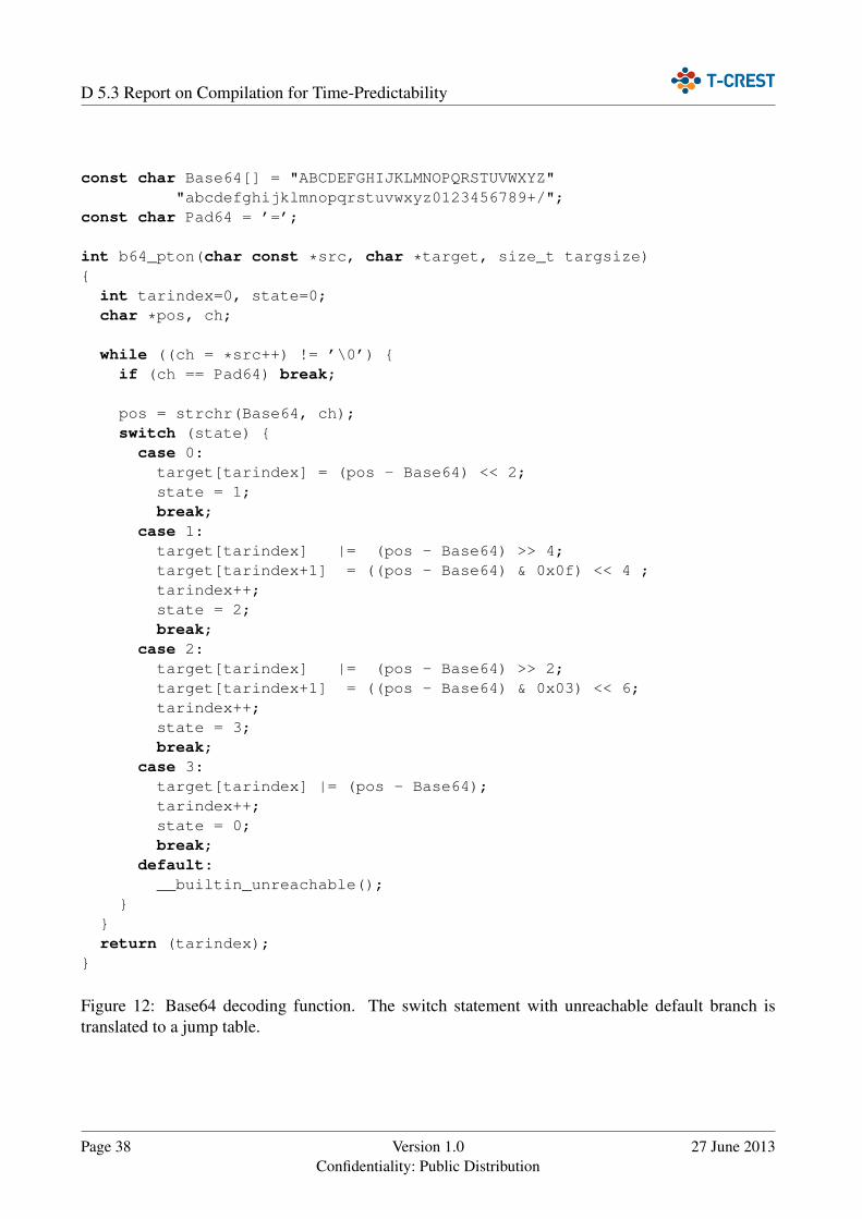
D 5.3 Report on Compilation for Time-Predictability
const char Base64[] = "ABCDEFGHIJKLMNOPQRSTUVWXYZ""abcdefghijklmnopqrstuvwxyz0123456789+/";
const char Pad64 = ’=’;
int b64_pton(char const *src, char *target, size_t targsize){
int tarindex=0, state=0;char *pos, ch;
while ((ch = *src++) != ’\0’) {if (ch == Pad64) break;
pos = strchr(Base64, ch);switch (state) {
case 0:target[tarindex] = (pos - Base64) << 2;state = 1;break;
case 1:target[tarindex] |= (pos - Base64) >> 4;target[tarindex+1] = ((pos - Base64) & 0x0f) << 4 ;tarindex++;state = 2;break;
case 2:target[tarindex] |= (pos - Base64) >> 2;target[tarindex+1] = ((pos - Base64) & 0x03) << 6;tarindex++;state = 3;break;
case 3:target[tarindex] |= (pos - Base64);tarindex++;state = 0;break;
default:__builtin_unreachable();
}}return (tarindex);
}
Figure 12: Base64 decoding function. The switch statement with unreachable default branch istranslated to a jump table.
Page 38 Version 1.0Confidentiality: Public Distribution
27 June 2013
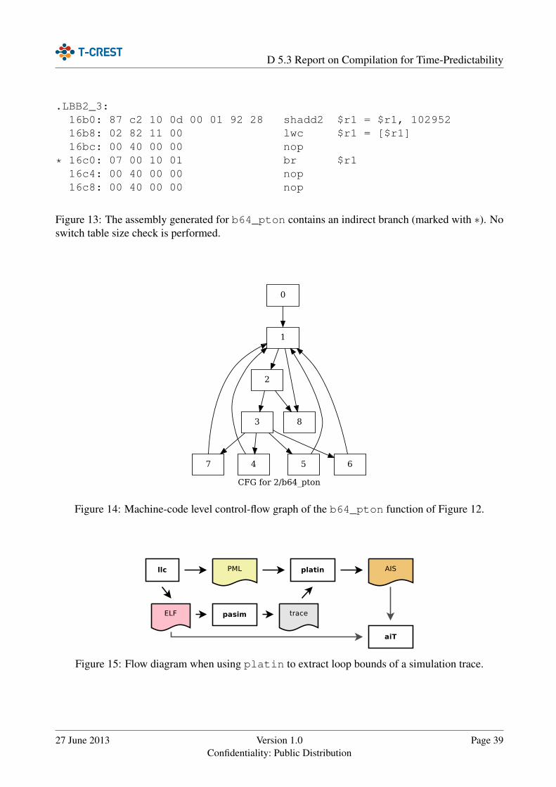
D 5.3 Report on Compilation for Time-Predictability
.LBB2_3:16b0: 87 c2 10 0d 00 01 92 28 shadd2 $r1 = $r1, 10295216b8: 02 82 11 00 lwc $r1 = [$r1]16bc: 00 40 00 00 nop
* 16c0: 07 00 10 01 br $r116c4: 00 40 00 00 nop16c8: 00 40 00 00 nop
Figure 13: The assembly generated for b64_pton contains an indirect branch (marked with ∗). Noswitch table size check is performed.
CFG for 2/b64_pton
0
1
7
2
83
4 5 6
Figure 14: Machine-code level control-flow graph of the b64_pton function of Figure 12.
Figure 15: Flow diagram when using platin to extract loop bounds of a simulation trace.
27 June 2013 Version 1.0Confidentiality: Public Distribution
Page 39

D 5.3 Report on Compilation for Time-Predictability
instruction ".LBB2_3" + 16 bytes branches to".LBB2_4", ".LBB2_5", ".LBB2_6", ".LBB2_7";# jumptable (source: llvm)
...loop ".LBB2_1" max 95 ;
# local loop header bound (source: trace)
Figure 16: The AIS annotations exported from the PML database for the b64_pton function.
Page 40 Version 1.0Confidentiality: Public Distribution
27 June 2013
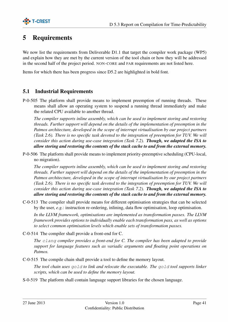
D 5.3 Report on Compilation for Time-Predictability
5 Requirements
We now list the requirements from Deliverable D1.1 that target the compiler work package (WP5)and explain how they are met by the current version of the tool chain or how they will be addressedin the second half of the project period. NON-CORE and FAR requirements are not listed here.
Items for which there has been progress since D5.2 are highlighted in bold font.
5.1 Industrial RequirementsP-0-505 The platform shall provide means to implement preemption of running threads. These
means shall allow an operating system to suspend a running thread immediately and makethe related CPU available to another thread.
The compiler supports inline assembly, which can be used to implement storing and restoringthreads. Further support will depend on the details of the implementation of preemption in thePatmos architecture, developed in the scope of interrupt virtualisation by our project partners(Task 2.6). There is no specific task devoted to the integration of preemption for TUV. We willconsider this action during use-case integration (Task 7.2). Though, we adapted the ISA toallow storing and restoring the contents of the stack cache to and from the external memory.
P-0-506 The platform shall provide means to implement priority-preemptive scheduling (CPU-local,no migration).
The compiler supports inline assembly, which can be used to implement storing and restoringthreads. Further support will depend on the details of the implementation of preemption in thePatmos architecture, developed in the scope of interrupt virtualisation by our project partners(Task 2.6). There is no specific task devoted to the integration of preemption for TUV. We willconsider this action during use-case integration (Task 7.2). Though, we adapted the ISA toallow storing and restoring the contents of the stack cache to and from the external memory.
C-0-513 The compiler shall provide means for different optimisation strategies that can be selectedby the user, e.g.: instruction re-ordering, inlining, data flow optimisation, loop optimisation.
In the LLVM framework, optimisations are implemented as transformation passes. The LLVMframework provides options to individually enable each transformation pass, as well as optionsto select common optimisation levels which enable sets of transformation passes.
C-0-514 The compiler shall provide a front-end for C.
The clang compiler provides a front-end for C. The compiler has been adapted to providesupport for language features such as variadic arguments and floating point operations onPatmos.
C-0-515 The compile chain shall provide a tool to define the memory layout.
The tool chain uses gold to link and relocate the executable. The gold tool supports linkerscripts, which can be used to define the memory layout.
S-0-519 The platform shall contain language support libraries for the chosen language.
27 June 2013 Version 1.0Confidentiality: Public Distribution
Page 41

D 5.3 Report on Compilation for Time-Predictability
The newlib library has been adopted for the Patmos platform, which provides a standardANSI C library.
A-0-521 The analysis tool shall allow defining assumptions, under which a lower bound can befound, i.e.a bound that is smaller than the strict upper bound, but still guaranteed to be >=WCET as long as the assumptions are true (e.g.instructions in one path or data used in thatpath fit into the cache).
Extending the clang compiler to support flow annotations in the source code is considered inTask 5.3. The annotations will be passed down to the WCET analysis by the tool chain. Flowannotations can be used to add additional flow constraints to the WCET analysis.
S-0-522 Platform and tool chain shall provide means that significantly reduce execution time (e.g.:cache, scratchpad, instruction reordering).
The LLVM framework provides several standard optimisations targeting execution time, suchas inlining or loop unrolling. The data scratchpad memory can be accessed with dedicatedmacros, which allow the programmer to manually utilize this hardware feature. Instructionreordering is performed statically at compile-time to reduce the number of stall cycles inthe processor. The stack cache provides a fast local memory to reduce the pressure on thedata cache and to obtain a better WCET bound. Task 5.3 is dedicated to the development ofoptimisations that focus on reducing the WCET.
P-0-528 The tool chain shall provide a scratchpad control interface (e.g.: annotations) that allowsmanaging data in the scratchpad at design time.
The SPM API has been integrated into the tool chain, which contains both low-level andhigh-level functions that allow copying data between SPM and external memory and to usethe SPM as buffer for predictable data processing, respectively. Accessing data items onthe SPM is possible with dedicated macros that use the address space attribute, which istranslated to memory access instructions with the proper type in the compiler backend.
C-0-530 The compiler may reorder instructions to optimise high-level code to reduce execution time.
Instructions are statically reordered to make use of delay slots and the second pipeline, andto minimise stalls during memory accesses.
C-0-531 The compiler shall allow for enabling and disabling optimisations (through e.g.: annotationsor command line switches).
In the LLVM framework optimisations are implemented as transformation passes. The LLVMframework provides options to individually enable each transformation pass, as well as optionsto select common optimisation levels which enable sets of transformation passes.
C-0-539 The compiler shall provide mechanisms (e.g.: annotations) to mark data as cachable oruncachable.
Variables marked with the _UNCACHED macro are compiled using the the cache bypassinstructions provided by Patmos to access main memory without using the data cache.
S-0-541 There shall be a user manual for the tool chain.
Page 42 Version 1.0Confidentiality: Public Distribution
27 June 2013

D 5.3 Report on Compilation for Time-Predictability
All tool chain source repositories contain a README.patmos file, which explains how tobuild and use the tools provided by the repository. Additional documentation of the tool chaincan be found in the patmos-misc repository. Further information about the LLVM compilercan be found in the LLVM user guide.2
5.2 Technology RequirementsC-2-013 The compiler shall emit the necessary control instructions for the manual control of the
stack cache.
The compiler emits stack control instructions to control the stack cache, so that data can beallocated in the stack cache.
C-4-017 The compiler shall be able to generate the different variants of load and store instructionsaccording to their storage type used to hold the variable being accessed.
The compiler backend supports all variants of load and store instructions that are currentlydefined by the Patmos ISA at the time of writing. Support for annotations to select the memorytype for memory accesses is provided by dedicated macros.
C-4-018 The storage type may be implemented by compiler-pragmas.
Support for annotations to select the memory type for memory accesses is provided by dedi-cated macros.
C-5-027 The compiler shall be able to compile C code.
The clang compiler provides a front-end for C. The compiler has been adapted to providesupport for language features such as variadic arguments and floating point operations onPatmos.
C-5-028 The compiler shall be able to generate code that uses the special hardware features providedby Patmos, such as the stack cache and the dual-issue pipeline.
The compiler uses special optimisations to generate code that uses the method cache, thestack cache and the dual-issue pipeline. Further optimisations that use the features providedby Patmos to reduce the WCET are implemented in Task 5.3.
C-5-029 The compiler shall be able to generate code that uses only a subset of the hardware featuresprovided by Patmos.
All code generation passes that optimise code for the Patmos architecture, such as stack cacheallocation and function splitting for the method cache, provide options to disable the optimi-sations and thus emit code that do not use the special hardware features of Patmos. Futureoptimisations will also provide options to disable the use of Patmos specific features.
C-5-030 The compiler shall support adding data and control flow information (i.e.: flow facts) to thecode, e.g.: in form of annotations.
Extending the compiler to support flow annotations in the source code is considered in Task5.3. The annotations will be passed down to the WCET analysis by the tool chain.
2http://llvm.org/docs/
27 June 2013 Version 1.0Confidentiality: Public Distribution
Page 43

D 5.3 Report on Compilation for Time-Predictability
C-5-031 The compiler shall provide information about potential targets of indirect function calls andindirect branches to the static analysis tool.
The compiler emits internal information such as targets of indirect jumps for jump ta-bles. The tool chain provides means to transform this information to the input format of theWCET analysis tool. Passing down additional annotations provided by the user (e.g. flowconstraints) is part of ongoing work (Task 5.3).
C-5-032 The compiler shall pass available flow facts to the static analysis tool.
The compiler emits internal information such as targets of indirect jumps for jump ta-bles. The tool chain provides means to transform this information to the input format of theWCET analysis tool. Passing down additional annotations provided by the user (e.g. flowconstraints) is part of ongoing work (Task 5.3).
6 Conclusion
In this document we presented techniques to generate time-predictable code for Patmos.
The method cache is a specialised instruction cache, which provides the property that cache missesonly occur at certain instructions. We described the algorithm for splitting functions into smallercachable regions, which is required in order to be able to compile large functions for Patmos.
The stack cache as a central component of Patmos requires support from the compiler, as controlinstructions have to be inserted explicitly. We presented two optimisations, for reducing both thenumber of stack cache instructions and the amount of data on the cache that potentially has to beloaded back from memory.
We showed how the local data scratchpad memory can be utilised for code patterns that interactsubobtimally with a data cache. This way, pressure is lowered from the data cache and the reductionof interferences allows both for better utilisation of the data cache and a more precise cache analysis.
The compiler backend has been extended to support bundling and scheduling of instructions for bothPatmos pipelines, but additional work in form of an integrated scheduling, bundling and delay slotfilling pass is required to achieve a performance increase by the dual-issue feature.
The single-path code transformation is a transformation performed by the compiler that producescode that exhibits a single dynamic program path, for different input data. It is a means to provideexecution times with little variability for tasks. We described the transformation steps along with anillustrative example.
We explained how we improve the analysability of the compiler-produced code by building an infras-tucture to tightly integrate the compilation and analysis phases. Information available in the compileris exported to an external file, which is processed by the platin tool kit. Among other uses, thisinformation is transformed to the input format of the aiT timing analysis tool, to enable timinganalysis to produce more precise results.
The upcoming deliverable D5.4 will discuss compiler optimisations that target the WCET of thereal-time tasks.
Page 44 Version 1.0Confidentiality: Public Distribution
27 June 2013
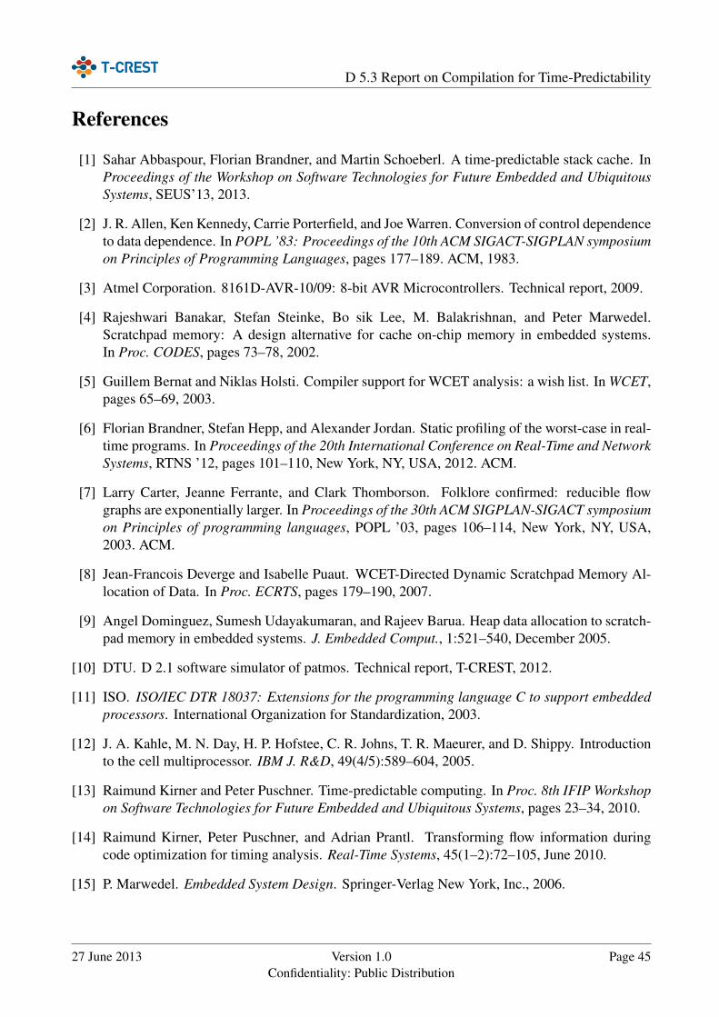
D 5.3 Report on Compilation for Time-Predictability
References
[1] Sahar Abbaspour, Florian Brandner, and Martin Schoeberl. A time-predictable stack cache. InProceedings of the Workshop on Software Technologies for Future Embedded and UbiquitousSystems, SEUS’13, 2013.
[2] J. R. Allen, Ken Kennedy, Carrie Porterfield, and Joe Warren. Conversion of control dependenceto data dependence. In POPL ’83: Proceedings of the 10th ACM SIGACT-SIGPLAN symposiumon Principles of Programming Languages, pages 177–189. ACM, 1983.
[3] Atmel Corporation. 8161D-AVR-10/09: 8-bit AVR Microcontrollers. Technical report, 2009.
[4] Rajeshwari Banakar, Stefan Steinke, Bo sik Lee, M. Balakrishnan, and Peter Marwedel.Scratchpad memory: A design alternative for cache on-chip memory in embedded systems.In Proc. CODES, pages 73–78, 2002.
[5] Guillem Bernat and Niklas Holsti. Compiler support for WCET analysis: a wish list. In WCET,pages 65–69, 2003.
[6] Florian Brandner, Stefan Hepp, and Alexander Jordan. Static profiling of the worst-case in real-time programs. In Proceedings of the 20th International Conference on Real-Time and NetworkSystems, RTNS ’12, pages 101–110, New York, NY, USA, 2012. ACM.
[7] Larry Carter, Jeanne Ferrante, and Clark Thomborson. Folklore confirmed: reducible flowgraphs are exponentially larger. In Proceedings of the 30th ACM SIGPLAN-SIGACT symposiumon Principles of programming languages, POPL ’03, pages 106–114, New York, NY, USA,2003. ACM.
[8] Jean-Francois Deverge and Isabelle Puaut. WCET-Directed Dynamic Scratchpad Memory Al-location of Data. In Proc. ECRTS, pages 179–190, 2007.
[9] Angel Dominguez, Sumesh Udayakumaran, and Rajeev Barua. Heap data allocation to scratch-pad memory in embedded systems. J. Embedded Comput., 1:521–540, December 2005.
[10] DTU. D 2.1 software simulator of patmos. Technical report, T-CREST, 2012.
[11] ISO. ISO/IEC DTR 18037: Extensions for the programming language C to support embeddedprocessors. International Organization for Standardization, 2003.
[12] J. A. Kahle, M. N. Day, H. P. Hofstee, C. R. Johns, T. R. Maeurer, and D. Shippy. Introductionto the cell multiprocessor. IBM J. R&D, 49(4/5):589–604, 2005.
[13] Raimund Kirner and Peter Puschner. Time-predictable computing. In Proc. 8th IFIP Workshopon Software Technologies for Future Embedded and Ubiquitous Systems, pages 23–34, 2010.
[14] Raimund Kirner, Peter Puschner, and Adrian Prantl. Transforming flow information duringcode optimization for timing analysis. Real-Time Systems, 45(1–2):72–105, June 2010.
[15] P. Marwedel. Embedded System Design. Springer-Verlag New York, Inc., 2006.
27 June 2013 Version 1.0Confidentiality: Public Distribution
Page 45
D 5.3 Report on Compilation for Time-Predictability
[16] Microchip Corporation. DS39632C: Microchip PIC18F2455 Data Sheet. Technical report,2006.
[17] Joseph C.H. Park and Mike Schlansker. On predicated execution. Technical report, HewlettPeckard Software and Systems Laboratory, May 1991.
[18] Isabelle Puaut and Christophe Pais. Scratchpad memories vs locked caches in hard real-timesystems: a quantitative comparison. In Proc. DATE, pages 1484–1489, 2007.
[19] Peter Puschner. Experiments with WCET-oriented programming and the single-path architec-ture. In Proc. 10th IEEE International Workshop on Object-Oriented Real-Time DependableSystems, Feb. 2005.
[20] Peter Puschner, Raimund Kirner, Benedikt Huber, and Daniel Prokesch. Compiling for timepredictability. In Proc. SAFECOMP 2012 Workshops (LNCS 7613), pages 382–391. Springer,2012.
[21] Peter Puschner, Raimund Kirner, and Robert G. Pettit. Towards composable timing for real-timesoftware. In Proc. 1st International Workshop on Software Technologies for Future DependableDistributed Systems, pages 1–5, 2009.
[22] G. Ramalingam. On loops, dominators, and dominance frontiers. ACM Trans. Program. Lang.Syst., 24(5):455–490, 2002.
[23] Vivy Suhendra, Tulika Mitra, Abhik Roychoudhury, and Ting Chen. WCET Centric Data Allo-cation to Scratchpad Memory. In Proc. RTSS, pages 223–232, 2005.
[24] TUV/DTU. D 5.2 initial compiler version. Technical report, T-CREST, 2012.
[25] Jack Whitham and Neil Audsley. Implementing Time-Predictable Load and Store Operations.In Proc. EMSOFT, pages 265–274, 2009.
[26] Jack Whitham and Neil Audsley. Investigating average versus worst-case timing behavior ofdata caches and data scratchpads. In Proc. ECRTS, pages 165–174, 2010.
[27] Jack Whitham and Neil Audsley. Explicit Reservation of Local Memory in a Predictable, Pre-emptive Multitasking Real-time System. In Proc. RTAS, pages 3–12, 2012.
[28] Jack Whitham and Neil Audsley. Optimal Program Partitioning for Predictable Performance.In Proc. ECRTS, pages 122–131, 2012.
Page 46 Version 1.0Confidentiality: Public Distribution
27 June 2013