cyclic bond behavior of different gfrp bar types
TRANSCRIPT

ST129-1
Building Tomorrow’s Society
Bâtir la Société de Demain
Fredericton, Canada
June 13 – June 16, 2018/ Juin 13 – Juin 16, 2018
CYCLIC BOND BEHAVIOR OF DIFFERENT GFRP BAR TYPES
Mohamed, Nayera1, Farghaly, Ahmed Sabry2 and Benmokrane, Brahim3,4 1 Former post-doctoral fellow, Department of Civil Engineering, University of Sherbrooke, Canada, Lecturer, Department of Civil Engineering, Assiut University, Egypt 2 Research Associate, Department of Civil Engineering, University of Sherbrooke, Canada 3 Professor, Department of Civil Engineering, University of Sherbrooke, Canada 4 [email protected]
Abstract: The cyclic bond stress-slip relationship of fiber-reinforced-polymer (FRP) is essential to have a reliable study of FRP-reinforced lateral resisting structural systems. To determine bond characteristics depending on the real case; a novel cyclic beam testing method was developed to accurately obtain the FRP bars’ bond performance under cyclic loading. Experimental results of twelve specimens are presented herein with different types of glass-FRP (GFRP) bar and compared the bond behavior of deformed steel bar. The tested parameters were; FRP bar surface texture (sand-coated, helically wrapped, and deformed bars), and loading conditions (monotonic, cyclic tension-tension, and cyclic tension-compression). The influence of the test parameters is discussed through analyzing the failure mechanism, average bond stress-slip, and local bond-stress distribution along bonded length. The results showed that cyclic loading had a significant influence on the bond behavior as well as the slip of GFRP bars. GFRP sand-coated bars and helically wrapped bars showed better bond behavior than that for deformed bars.
1 INTRODUCTION
Actual structures are subjected to load reversals (live load, earthquake, and wind) during their life spans like shear walls, columns, and beam–column connections (Mohamed et al. 2014). Sustained repeated loading may cause more damage to the bond between the reinforcing bar and the concrete, thereby can lead to an unexpected increase in the anchoring length needed for safe use of the bars. Reinforcing with Fiber-Reinforced-Polymer (FRP) have quite different bond characteristics, which are strongly dependent on mechanical and physical properties of external layer of FRP rods (Katz 1998; Ehsani et al., 1997). On the other hand, because of the lack of well-established standards, a wide variety of FRP reinforcing bars are currently commercially available, ranging from the simple smooth reinforcing bars to bars treated to improve bond characteristics.
There are many developed surface preparations which shows good results in approving bond behavior such as ribbed bars, sand coated bars, peel ply bars. Therefore, in this study bond behavior for different surface treated FRP bars compared to steel reinforcing bars under reversed cyclic loads. The main objective of the experimental program presented herein is to study the bond–slip relationship under monotonic tension, tension–tension and tension–compression reversed cyclic loading. Therefore, a test setup was designed and fabricated to meet the needs and conditions of this study.

ST129-2
Many investigations have been conducted on pullout tests to study the bond characteristics of fiber-reinforced-polymer (FRP) reinforcement (Baena et al. 2009). The concrete and reinforcement in such pullout test setups, however, operate under different stress states that do not reflect actual structural behavior. Consequently, a beam bending test was conducted (Ashtiani et al. 2013) to represent as closely as possible, the conditions occurring in reinforced concrete structural elements. This beam test placed the tested bar and concrete under the same stresses. This test, however, studied the bond properties of FRP bars only under monotonic tensile-loading conditions.
To combine the advantages of both pullout and beam tests and avoid their disadvantages, an innovative test setup and specimens were designed and fabricated. The test setup was designed to (a) determine the bond characteristics depending on the actual case; loading of the concrete block to be transferred to FRP-reinforced bars, under the same stress conditions and (b) allow different loading conditions of monotonic either in tension or compression; reversed low cyclic loading in tension–tension, compression–compression, and tension–compression; and fatigue loading either in tension or compression; (c) use a simplified miniature model specimen to allow mass production(d) prevent premature failure from direct loading of the FRP bar which might cause undesirable compression/buckling failure instead of bond failure.
2 TEST PROGRAM
2.1 Test setup
The test setup was designed as a composite section, consisting of a steel I beam and concrete attached together with studs cast in the concrete specimen, and a real hinge at the I beam’s mid-span (Figure1). The steel I beam was chosen to fit the minimum needed width of the concrete specimen. The I-beam was 560 mm high and 317 mm wide. The steel intermediate hinge was designed and fabricated with capablity of taking both compressive and tensile forces with negligable friction.
Figure 1: Designed beam for bond test
Figure 2: Roller and hinge supports
Concrete specimen
StudSteel beam
100
250
290
Unit: mm
500
Hinge
Steel I beam
11501150 5 772490
Tested FRP bar
Studs
Concrete specimen
P
a b

ST129-3
The setup was designed to fit all types and sizes of FRP bars from #2 (6 mm diameter) to #12 (36 mm diameter). The concrete specimen was connected to the simply supported steel I beam with steel stud connectors before casting. During testing, the steel I-beam was connected to the concrete block with steel stud connectors placed in the concrete specimen. Studs were also used in transporting the specimen from the casting site to the testing site with two steel plates on the top and bottom to prevent tension or torsion of the FRP bar that might occur during transportation, as shown in Figure 3.
Figure 3: Designed test setup
2.2 Tested Bar
The tested bar had total length of 1000 mm for all specimens. The bars were bonded with total length embedded in the concrete block equal to (Ld), and free-end lengths of 75 mm on each side. The length between the two concrete blocks the bar was bare. Figure 4 shows that this part of the bare bar was grouted before casting to prevent premature buckling failure under compression. The bars were grouted along 180 mm at mid-span. The grouting was a steel tube centred on the bar and then filled with cement grout. Bond breakers were used at the loaded end of the concrete block to minimize stress concentration near the concrete surface. They are made of plastic tube around the tested bar with a length not less than 5 db and a diameter of 20 mm (Figure 4).
Figure 4: Preparation of tested bar with bond breakers and mid-span grouting
Bonded length (Ld)
7Unbonded length (L)
40
7
40
5
7 5
1000
7
25
290
FRP bar
FRP bar
ST129-4
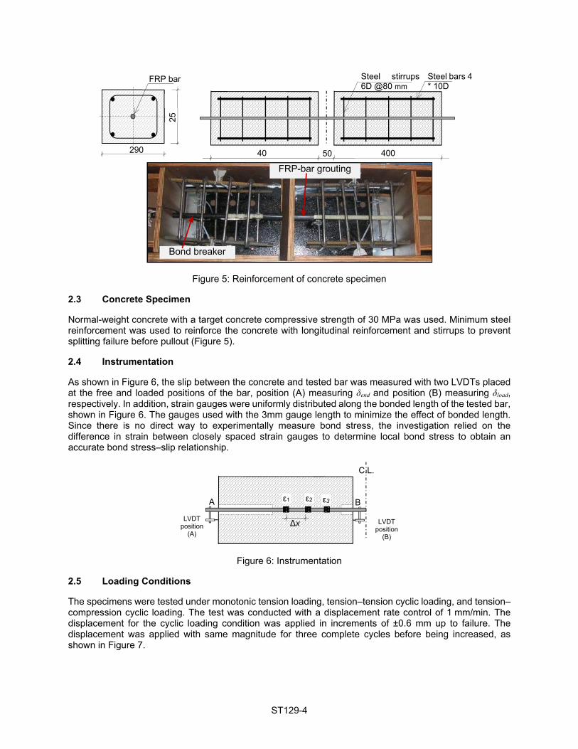
Figure 5: Reinforcement of concrete specimen
2.3 Concrete Specimen
Normal-weight concrete with a target concrete compressive strength of 30 MPa was used. Minimum steel reinforcement was used to reinforce the concrete with longitudinal reinforcement and stirrups to prevent splitting failure before pullout (Figure 5).
2.4 Instrumentation
As shown in Figure 6, the slip between the concrete and tested bar was measured with two LVDTs placed at the free and loaded positions of the bar, position (A) measuring δend and position (B) measuring δload, respectively. In addition, strain gauges were uniformly distributed along the bonded length of the tested bar, shown in Figure 6. The gauges used with the 3mm gauge length to minimize the effect of bonded length. Since there is no direct way to experimentally measure bond stress, the investigation relied on the difference in strain between closely spaced strain gauges to determine local bond stress to obtain an accurate bond stress–slip relationship.
Figure 6: Instrumentation
2.5 Loading Conditions
The specimens were tested under monotonic tension loading, tension–tension cyclic loading, and tension–compression cyclic loading. The test was conducted with a displacement rate control of 1 mm/min. The displacement for the cyclic loading condition was applied in increments of ±0.6 mm up to failure. The displacement was applied with same magnitude for three complete cycles before being increased, as shown in Figure 7.
Steel stirrups 6D @80 mm
Steel bars 4 * 10D
400 40 50
25
290
FRP bar
FRP-bar grouting
Bond breaker
LVDT position
(A)
LVDT position
(B)
Δx
ε1 ε2 ε3A B
C.L.

ST129-5
Tension–tension loading Tension–compression loading
Figure 7: Test procedure
The test setup is designed to be loaded in three-point bending, as shown in Figures 1, 3. The force induced in the FRP bar can be directly calculated as:
[1] F = PL/2h = 0.9 P
where L is the total span of beam specimen between supports, h is the vertical distance between centers of the steel hinge and FRP-bar axis, and P is the applied load.
3 EXPERIMENTAL PROGRAM
The experimental program consisted of 36 specimens with different bar types, different bar sizes and bonded lengths. Herein we present only 12 specimens for studying one parameter of different bar types. The presented specimens herein are glass fibre reinforced-polymer (GFRP) bar type with different bar coating and surface and compared to deformed steel bar. The bars were the same diameter of GFRP #3 (db = 9.5 mm) and steel #3 (db =9.5 mm). The bonded length of the GFRP and steel bars was equal to 95 mm, corresponding to Ld = 10 db.
The tested bars were subjected to three different types of stresses, the unidirectional monotonic tension loading (M) which is commonly tested and designers use to calculate development length, the unidirectional repeated tension loading (TT) which is usually the case of bridge members, and reversed cyclic loading which applies reversals from tension to compression during a cyclic load (TC) as typically the case of earthquake and wind loading.
Specimen GP-3 is GFRP #3 bars with sand coated with coarse sand and helically wrapped, while GB-3 is GFRP #3 sand coated with fine sand and helically wrapped bars, GS-3 is GFRP #3 ribbed bars, and ST-3 is deformed steel bars with ribs. Figure 8 shows the tested 4 types of reinforcing bars. Each type of bars has three specimens, M for monotonic loading, TT for tension–tension cyclic loading, and TC for tension–compression cyclic loading.
Cen
tral
Dis
plac
emen
t (m
m)
No. of cycles
± 0.
6 m
m
Cen
tral
Dis
plac
emen
t (m
m)
No. of cycles
± 1.
2 m
m
± 2.
4 m
m
± 1.
8 m
m
0.6
mm
1.2
mm
2.4
mm
1.8
mm

ST129-6
Figure 8: Types of bars used in testing
4 RESULTS AND DISCUSSION
While ACI 318-14 and CSA A23.3-14 does not require specific checks for bond stresses, the required development length is based on the assumed uniformly distributed bond stress over the bonded length of the bar. In this experimental investigation, after calculating the tension or compression force (F) on the tested bar from Eq. 1, the average bond stress ( avg) was then calculated from the force (F) in the bar, assuming a uniform distribution of bond stresses within the bond length, as follows:
[2]
where db is the bar diameter and Ld is the bonded length. In the tests presented, Ld = 10 db. Figure 9 presents the bond–slip relationships of all tested specimens. Figure 9 shows the average bond stress- slip relationship at loaded side (δload) and at free-end unloaded side (δend) for all tested specimens. Table 1 provides the experimental results for the specimens in terms of linear bond stress ( e), maximum bond stress ( max), and the corresponding loaded-end slip (δload max) from LVDT at position B (Fig. 6), failure bond stress ( fail) at the free-end slip (δend) equal to 3 mm (Ashtiani et al. 2013), and the corresponding failure loaded-end slip (δload fail).
Table 1: Summary of experimental results
Specimens GB-3 GP-3 GS-3 ST3 M TT TC M TT TC M TT TC M TT TC
fc’ (MPa) 39.5 30.2 30.2 39.5e (MPa) 9.2 7.8 7.9 8.2 7.9 6.7 8.0 6.9 6.6 7.0 6.2 6.4
max (MPa) 11.7 8.9 10.4 18.5 18.2 -# 11.2 8.9 8.7 18.1 17.5 16.3 δload max (mm) -# 1.46 1.4 2 1.6 1.1 1.9 1.3 1.1 1.4 1.5 1.5
fail (MPa) 11.9 6.8 6.3 17.5 12.6 11.9 7.7 3.7 3.1 13.6 9.5 7.1 δload fail (mm) 3.8 3.6 3.4 4.1 3.9 3.5 4.7 3.4 3.2 4.0 3.4 3.3
e elastic bond stress measured at δend =0.05 mm, δload max measured slip corresponding to the maximum bond stress max, fail failure bond stress at end slip δend= 3 mm, δload fail failure slip at δend =3 mm, #Missing data.
GB-3 GS-3 GP-3 ST-3

ST129-7
Figure 9: Bond stress–slip relationship for (a) GB-3, (b) GP-3 (continued)
As shown in Figure 9, the bond stress versus slip relationship in all loading cases reveals a gradual increase in bond stress until the maximum bond strength was reached. This ascending behavior was typical for all types of reinforcement. At a bond stress ranged between 6.5 - 9 MPa for all specimens, the end slip did not exceed 0.05 mm with linear bond behavior. This value nominated as e was reached during the first three cycles of 0.6 mm displacement for cyclic testing. The sand-coated bars GB-3 and GP-3 experienced the higher e compared to the steel bar and GS-3, which where deformed ribbed bars.
The bond stress continued to increase nonlinearly up to the maximum bond strength. The maximum bond stress max was reached at average loaded slip δload of 1.5-2 mm for all specimens under all types of loading. The value of maximum bond stress varied for each bar type. Under monotonic loading, the steel bar reached bond stress of 18.1 MPa and GP-3 had similar bond stress of 18.5 MPa. GB-3 and GS-3 reached max of 11.7, 11.2 MPa, respectively, with lower maximum bond strength. The type of loading affected the maximum bond strength of all reinforcement bars, but GFRP bars were more affected than the steel bar. The reduction of maximum bond stress for steel bar was 10% when subjected to TT and TC cyclic loading. While for GFRP bars, the reduction for GS-3, GP-3, and GB-3 was 21%, 2%%, 24%, respectively, for TT cyclic loading, and for TC cyclic loading, the reduction was 22%, 18%, and 12% for GS-3, GP-3, andGB-3, respectively. It can be notice that, this reduction was not based on the coating of the GFRP bars but on the contacting layer between the bar and the surrounding concrete. Further analysis of the crack propagation and crack width of the concrete surrounding the bar is needed as it may clarify this point.
0
5
10
15
20
0 2 4 6 8 10 120
5
10
15
20
0 2 4 6 8 10 12
0
5
10
15
20
0 2 4 6 8 10 12
0
5
10
15
20
0 2 4 6 8 10 12
0
5
10
15
20
0 2 4 6 8 10 12
0
5
10
15
20
0 2 4 6 8 10 12(a) GB-3 (b) GP-3
Bon
d st
ress
(M
Pa)
Slip (mm)
Unloaded Loaded
Bon
d st
ress
(M
Pa)
Slip (mm)
Unloaded Loaded
Bon
d st
ress
(M
Pa)
Slip (mm)
Unloaded Loaded
Bon
d st
ress
(M
Pa)
Slip (mm)
Unloaded Loaded
Bon
d st
ress
(M
Pa)
Slip (mm)
Unloaded Loaded
Bon
d st
ress
(M
Pa)
Slip (mm)
Unloaded Loaded
GB-3 MT
GB-3 TT
GB-3 TC
GP-3 MT
GP-3 TT
GP-3 TC

ST129-8
Figure 9: Bond stress–slip relationship for (c) GS-3, (d) ST-3 (continued)
The bond stress-slip relationship after reaching the maximum bond stress experienced a reduction in bond stress for all types of bars except for the monotonic loading (M) of GB-3 and GP-3 (Figure 9). This phenomenon was reported by Aiello et al. 2007 and could be revealed from the sand-coating of GB-3 and GP-3 which caused friction between the bar and the surrounding concrete that maintained the high bond stress between the bar and concrete. This friction was lost when the type of loading is changed to cyclic (TT) or reversed cyclic (TC) loading. Meanwhile, the descending branch of bond stress-slip relationship for ribbed deformed bars of GS-3 and ST-3 was evidenced with loss of about 0.25 and 0.3 of maximum bond strength, respectively, when subjected to monotonic loading (M). During cyclic TT and TC, the lose in max was about 0.6 and 0.5 for GS-3 and ST-3, respectively. ACI 408.2R-12 specified the lower and upper bond of corresponding average bond stress at ultimate limit state for deformed steel bars in tension as 0.5 and 7.2 MPa, respectively, which is safely reached in all bar types.
5 CONCLUSIONS
Due to the new application of GFRP reinforcement in seismic lateral resisting systems, there is a need to study the bond behavior under cyclic loading. For this purpose, a novel test setup was designed to perform testing under reversed cyclic loading. The bond stress–slip relationship was obtained for monotonic tension, tension–tension cyclic, and tension–compression reversed cyclic deformation. The twelve presented test
0
5
10
15
20
0 2 4 6 8 10 12
0
5
10
15
20
0 2 4 6 8 10 12B
ond
stre
ss (
MP
a)
Slip (mm)
0
5
10
15
20
0 2 4 6 8 10 12
Unloaded Loaded
Bon
d st
ress
(M
Pa)
Slip (mm)
Unloaded Loaded
Bon
d st
ress
(M
Pa)
Slip (mm)
Unloaded Loaded
0
5
10
15
20
0 2 4 6 8 10 12
0
5
10
15
20
0 2 4 6 8 10 12
0
5
10
15
20
0 2 4 6 8 10 12
Bon
d st
ress
(M
Pa)
Slip (mm)
Unloaded Loaded
Bon
d st
ress
(M
Pa)
Slip (mm)
Unloaded Loaded
Bon
d st
ress
(M
Pa)
Slip (mm)
Unloaded Loaded
(c) GS-3 (d) ST-3
GS-3 MT
GS-3 TT
GS-3 TC
ST-3 MT
ST-3 TT
ST-3 TC

ST129-9
specimens used three different GFRP bar types; two types were with sand-coated surfaces and one was ribbed, which were compared to deformed steel bar with the same diameter.
Bond performance for GFRP bars under cyclic and reversed cyclic loading showed different bond stress-slip behavior than that of monotonic loading. While bond stress-slip behavior of steel bars followed the monotonic behavior up to the maximum bond strength, the behavior was different for GFRP bars. It was also noted that, under monotonic loading, the GFRP bars with sand-coated and helically wrapped surface showed bond stress-slip relation with no reduction after reaching maximum bond strength, in which the maximum bond stress was maintained as the slip increased. The bond stress decreased considerably under cyclic and reversed cyclic loading once the maximum bond strength had been achieved. For the ribbed GFRP and steel bars the typical bond stress-slip behavior of gradual increase in bond stress till reaching maximum bond strength followed by reduction in bond strength up to failure. Meanwhile, the reduction in bond strength was augmented when the bar is subjected to cyclic or reversed cyclic loading. The results revealed the need to model bond stress-slip relationship for GFRP bars differ from that for monotonic loading and differ from that of conventional steel bars.
Acknowledgements
The authors wish to acknowledge the financial support of the Natural Sciences and Engineering Research Council of Canada (NSERC) – NSERC/Industry and Canada Research Chairs Programs -, and the Fonds de la recherche du Québec sur la nature et les technologies (FRQ-NT). Thanks should be extended to the technical staff of the structural lab in the Department of Civil Engineering at the University of Sherbrooke.
References
ACI Committee 318, 2014. Building Code Requirements for Structural Concrete and Commentary (ACI 318-14). American Concrete Institute, Farmington Hills, MI, 503 pp.
ACI-ASCE Committee 408, 2012. Report on Bond of Steel Reinforcing Bars Under Cyclic Loads (ACI 408.2R-12). American Concrete Institute, Farmington Hills, MI, 35 pp.
Aiello, M.A., Leone, M., and Pecce, M. 2007. Bond performances of FRP rebars-reinforced concrete. Journal of Materials in Civil Engineering, ASCE, 19(3): 205-213.
Ashtiani, M.S., Dhakal, R.P., Scott, A.N., & Bull, D.K. 2013. Cyclic beam bending test for assessment of bond–slip behavior. Engineering Structures, Elsevier, 56: 1684-1697.
Baena, M., Torres, L., Turon, A., & Barris, C. 2009. Experimental study of bond behaviour between concrete and FRP bars using a pull-out test. Compos Part B, Elsevier, 40: 784-797.
Canadian Standards Association A23.3. 2014. Design of concrete structures standard (CSA A23.3-14). Mississauga, ON, Canada, 240 pp.
Mohamed, N., Farghaly, A., Benmokrane, B., & Neale, K. (2014). Experimental investigation of concrete shear walls reinforced with glass fiber–reinforced bars under lateral cyclic loading. Journal of Composites for construction, ASCE, 18(3), A4014001.