cyber-physical software systems for smart ... - ceur-ws.orgceur-ws.org/vol-1156/paper5.pdf · smart...
TRANSCRIPT

Cyber-Physical Software Systems forSmart Worlds: A Case Study ofIntelligent Transportation System
Kaliappa Ravindran
City College of CUNY and Graduate Center,Department of Computer Science,
160 Convent Avenue,New York, NY 10031, [email protected]
Abstract. The paper discusses the design of cyber-physical systemssoftware around intelligent physical worlds (IPW). An IPW is the embod-iment of control software functions wrapped around the external worldprocesses. The IPW performs core domain-specific activities while adapt-ing its behavior to the changing environment conditions and user inputs.The IPW exhibits an intelligent behavior over a limited operating re-gion of the system — in contrast with the traditional models wherethe physical world is basically dumb. To work over a wider range ofoperating conditions, the IPW interacts with an intelligent computa-tional world (ICW) to patch itself with suitable control parameters andrules/procedures relevant in those changed conditions. The modular de-composition of a complex adaptive system into IPW and ICW lowersthe overall software complexity, simplifies the system verification, andpromotes an easier evolution of system features. As an intelligence func-tionality, a network system in our approach employs redundant sensingas a means to improve the quality of detection & aggregation of eventsoccurring in the environment. The paper illuminates our concept of IPWwith case study of vehicular traffic management network.
1 Introduction
A cyber-physical system (CPS) allows the computational processes to interactwith the physical world processes in a way to impact how the latter is structuredand designed, and vice versa. We elevate the definition of an embedded systemby eliminating the hardware-centric boundaries of physical processes. An appli-cation B that is traditionally viewed as a non-embedded system because of itsheavy software leaning can now be brought into the fold of CPS with a notion ofintelligent physical world Ap. Here, Ap can be an embodiment of diverse softwarefunctions, with the embedded hardware instantiating the raw physical processes(RPP). The RPPs are dumb physical component ensembles through which a
53

system interacts with its (hidden) external environment, such as: steering link-ages to turn a car on the road, network link/router to transport data packets,and conveyor belt to move assembled parts.
The sub-systemAp is more than a collection of physical components RPP, butinstead consists of a software wrapper that controls RPP in such a way to infusea self-contained and intelligent behavior1. From a programming standpoint, theRPP is abstracted as a function g∗(I,O∗, s∗, E∗) that takes an input I andresponds with an output O∗, where s∗ is the current state of RPP and E∗ isthe uncontrollable external environment incident on RPP. Here, O∗ depicts theobservation of a transition in the state of physical processes s∗, with the time-scale of response hidden as part of the abstraction. For e.g., g∗(· · ·) may representthe end-to-end path in a data network, where I and O∗ denote the injection ofa packet flow and its delivery respectively, s∗ is the available bandwidth, andE∗ depicts a packet-loss phenomenon impacting the flow. As another example,g∗(· · ·) may be the motor in an industrial control system, where I and O∗ denotethe electrical signal and rotational speed respectively, s∗ is the residual motortorque, and E∗ depicts an electrical and/or mechanical disturbance impactingthe motor speed. Our idea is to extend g∗(I,O∗, s∗, E∗) into a coherent intelligentphysical world Ap that is self-aware and can repair itself (in a limited way) fromthe damages caused by environment conditions E∗. Ap is augmented by anintelligent computational world Ac that manages the overall operations of Ap.Their composition to yield an adaptive application system B is denoted as:
B ≡ Ap ⊕Ac,
where Ap is wrapped around g∗(I,O∗, s∗, E∗) and the operator ’⊕’ depicts theinter-module flow of signals between Ap and Ac: which includes a management-oriented feedback from Ap to Ac. The signal flow is at a meta-level, while theAc-Ap concrete interactions are determined by their programming boundaries.We allude to a ’monitor-and-control’ interaction (M&C) initiated by Ac on Ap,and vice versa.
An example of Ap is a smart home that sets the heating and cooling param-eters based on the occupancy, ambient conditions, comfort level, and the like.Here, Ac may be a Home Service Center outsourced with the task of manag-ing the intelligent home remotely by setting the right parameters and operatingprocedures (say, different procedures for winter and summer operations). In atarget tracking system as another example, the radar units reporting the imagesof objects in a terrain to a data fusion center may also notify the terrain char-acteristics to enable the choice of image processing algorithms: say, to meet thetarget detection accuracy needs. Here, Ap is the group of radar units implantedwith parameter-adjustable image processing algorithms (say, track resolution)and Ac is the fusion center deciding on the right set of algorithms suitable forthe terrain.
1 The physical world Ap in our CPS view includes software functions that were hithertoa part of the control system software external to the RPP.
54
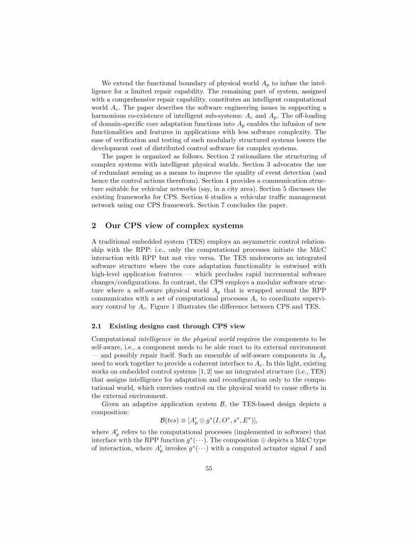
We extend the functional boundary of physical world Ap to infuse the intel-ligence for a limited repair capability. The remaining part of system, assignedwith a comprehensive repair capability, constitutes an intelligent computationalworld Ac. The paper describes the software engineering issues in supporting aharmonious co-existence of intelligent sub-systems: Ac and Ap. The off-loadingof domain-specific core adaptation functions into Ap enables the infusion of newfunctionalities and features in applications with less software complexity. Theease of verification and testing of such modularly structured systems lowers thedevelopment cost of distributed control software for complex systems.
The paper is organized as follows. Section 2 rationalizes the structuring ofcomplex systems with intelligent physical worlds. Section 3 advocates the useof redundant sensing as a means to improve the quality of event detection (andhence the control actions therefrom). Section 4 provides a communication struc-ture suitable for vehicular networks (say, in a city area). Section 5 discusses theexisting frameworks for CPS. Section 6 studies a vehicular traffic managementnetwork using our CPS framework. Section 7 concludes the paper.
2 Our CPS view of complex systems
A traditional embedded system (TES) employs an asymmetric control relation-ship with the RPP: i.e., only the computational processes initiate the M&Cinteraction with RPP but not vice versa. The TES underscores an integratedsoftware structure where the core adaptation functionality is entwined withhigh-level application features — which precludes rapid incremental softwarechanges/configurations. In contrast, the CPS employs a modular software struc-ture where a self-aware physical world Ap that is wrapped around the RPPcommunicates with a set of computational processes Ac to coordinate supervi-sory control by Ac. Figure 1 illustrates the difference between CPS and TES.
2.1 Existing designs cast through CPS view
Computational intelligence in the physical world requires the components to beself-aware, i.e., a component needs to be able react to its external environment— and possibly repair itself. Such an ensemble of self-aware components in Ap
need to work together to provide a coherent interface to Ac. In this light, existingworks on embedded control systems [1, 2] use an integrated structure (i.e., TES)that assigns intelligence for adaptation and reconfiguration only to the compu-tational world, which exercises control on the physical world to cause effects inthe external environment.
Given an adaptive application system B, the TES-based design depicts acomposition:
B(tes) ≡ [A′p ⊕ g∗(I,O∗, s∗, E∗)],
where A′p refers to the computational processes (implemented in software) thatinterface with the RPP function g∗(· · ·). The composition ⊕ depicts a M&C typeof interaction, where A′p invokes g∗(· · ·) with a computed actuator signal I and
55

Layered (onion-peel) structureCyber-physical System (CPS) view
Physical
world
processes
Computational
world
processes
M & Cinteraction
M & Cinteraction
Software layer A”p withlimited intelligence
C C M
C
M
RPP
Software layer Ac withaugmented intelligence
CC
MMM M C
Limited-range adaptive operations
1. Executed over fast time-scales
2. Functions touched are separable
Wide range of adaptive operations1. Executed over slow time-scales2. Functions touched are non-separable
app
lica
tio
nsy
stem
B(cps)
Traditional Embedded System (TES) viewM & C: monitor-and-control
Computational world processes A’p(intelligent software layer)
C
M
C M
C
M
Physical
world
processes
Computational
world
processes
M & Cinteraction
RPP
M Ccompounded effects of alltypes of adaptive operations
app
lica
tio
nsy
stem
B(tes)
RPP: Dumb physical world processes[abstracted as a function g*(I,O*,s*,E*)]
Fig. 1. TES versus CPS
observing the output response O∗. The TES structure assigns intelligence to A′p,with the latter interfacing with g∗(· · ·) through signaling hooks to actuate thetrigger mechanisms, thereby moving the RPP move from one operating point toanother. Thus, CPS-based design depicts an alternate system composition:
B(cps) ≡ [Ac ⊕Ap] ⊇ B(tes),
where Ap ≡ [A′′p ⊕ g∗(I,O∗, s∗, E∗)] depicting the CPS software functions thatwrap local intelligence around the raw physical world process over a limited op-erating region, such that A′′p ⊆ A′p. Ac is the computational process to infusea broader intelligence to the operations of B that are otherwise difficult in aTES-based design. B(cps) can easily be infused with new features and/or haveits existing features augmented by algorithm plug-ins to modify the function-ality of Ap, as orchestrated by policy-based mechanisms and adaptation logicprogrammed in Ac. For example, the QoS feature for packet transport over anetwork data path that hitherto allows controlling the mean packet delay canbe augmented with delay jitter control as well, by implanting a modified packetscheduling algorithm along the path. The raw physical world g ∗ (· · ·) is itselfconsidered as dumb, providing only the basic functional components. An invoca-tion of these components comes from the upper layer processes: A′′p in the CPSapproach and A′p in the TES approach.
Due to the underlying state-machine complexity of the system as a whole,the TES-based integrated approach does not lend itself well for a seamless ad-dition/removal of automated system features, entails difficulty in incrementalsoftware changes, and makes the testing/maintenance of system software a labor-intensive activity.
56

2.2 CPS-based structure of complex systems
We employ the principles of piece-wise linearity and separability of functionsdescribing the system model [3], to determine the operating regions of Ap wherethe system-level computations of future trajectories (in a control-theoretic sense)are simpler and fall within the ambit of local intelligence. When the systembehavioral changes satisfy linearity/separability, Ap can repair itself. The self-repair can be via a local built-in mapping function that is instantiated with theparameters supplied by Ac for that operating region. An example is the adjustingof TCP flow control window size based on small changes in packet round-tripdelay (RTT) over the transport network. On the other hand, if the behavioralchanges are larger taking the system into non-linear regions, Ap may report thechanges to Ac for the latter to adjust the parameters for the new region of systemoperations: say, by using domain-specific policy functions. In the TCP example,the protocol itself may be changed to aggressively adjust the window size whenthe RTT swings are large. Ac is wired with domain-specific policies and rulesto evaluate the linearity and separability conditions, and then patch Ap withappropriate parameters and procedures2.
Ap operates over a much faster time-scale than Ac. This is because the controlloop in Ap is self-contained to react to the smaller changes that typically occurfrequently in the external environment. Whereas, Ac steps in only when largerchanges occur in the external environment — which are less frequent (e.g., anetwork suffering a DOS attack, a car tire losing air due to a puncture). Ap
embodies the core domain-specific functionality, and Ac is delegated with anexternal management role using parameterized procedures and rules specific tothe domain. See Figure 2 for an illustration of the functional blocks to realize thehierarchical control relationship between Ac and Ap. Our software engineeringapproaches orchestrate such a delineation of Ap and Ac.
The true model of RPP may not be known to Ap, i.e., it is difficult to expressg∗(I,O∗, s∗, E∗) in a closed-form. So, the determination of I is governed by acomputational model of RPP, denoted as g(I,O∗, s, E), that is programmedinto the controller module of Ap. This localized incremental adaptation strategyemployed in Ap allows determining the final input I needed to attain a stableoutput P ′ — where P ′ = O∗(L) with L depicting the control round when Ap
reaches convergence. Any mismatch between P ′ and Pref is then notified to Ac
for appropriate recovery. The intelligent behavior of Ap is however feasible onlyover a limited operating region, as determined by Ac.
The system output O∗, which is of interest to the controller modules in Ap
and Ac, is often easier to measure (e.g., packet transfer latency on a networkpath). The uncontrolled external environment E∗, which impacts the systemoutput in complex ways, is however hard to measure (e.g., bandwidth depletionalong the path). Our partitioning of observation space into O∗ and E∗ arisesfrom these considerations. We assume a finite world where the parameter values
2 The update of controller sub-systems in Ap during run-time is known as patching[4]. It enables a hierarchical control with simple controllers programmable at lowerlevels (such as automotive ECUs supplied by OEM vendors).
57
externalenvironmentconditions E*
(say, component failuresand outages)
system
output O*controllerplant
input I
P’=M*(O*)
referenceinput
PrefPref-P’
Em
bed
ded
Sy
stem
ap
pli
cati
on
Situation assessment
module (SAM)[non-linearity checks,
environment assessment, . .]
Control algorithmmanager
physicaleffects onexternalworld
(e.g
., se
nso
r sp
ecs,
pla
nt m
odel
g(I
,O*,s
,E),
adap
tati
on r
ule
, . . )
Raw physicalprocesses
g*(I,O*,s*,E*)
TSF
pla
nt
stat
e(s
amp
led
)
s s*
TSF
alg
ori
thm
&p
ara
met
erp
atc
hin
g
TSF:time-scale filter
stab
iliz
ed
contr
ol
erro
r
stab
lest
ate
observer
COMPUTATIONALWORLD Ac
PHYSICALWORLD Ap
parametricrepresentation E E*
states*
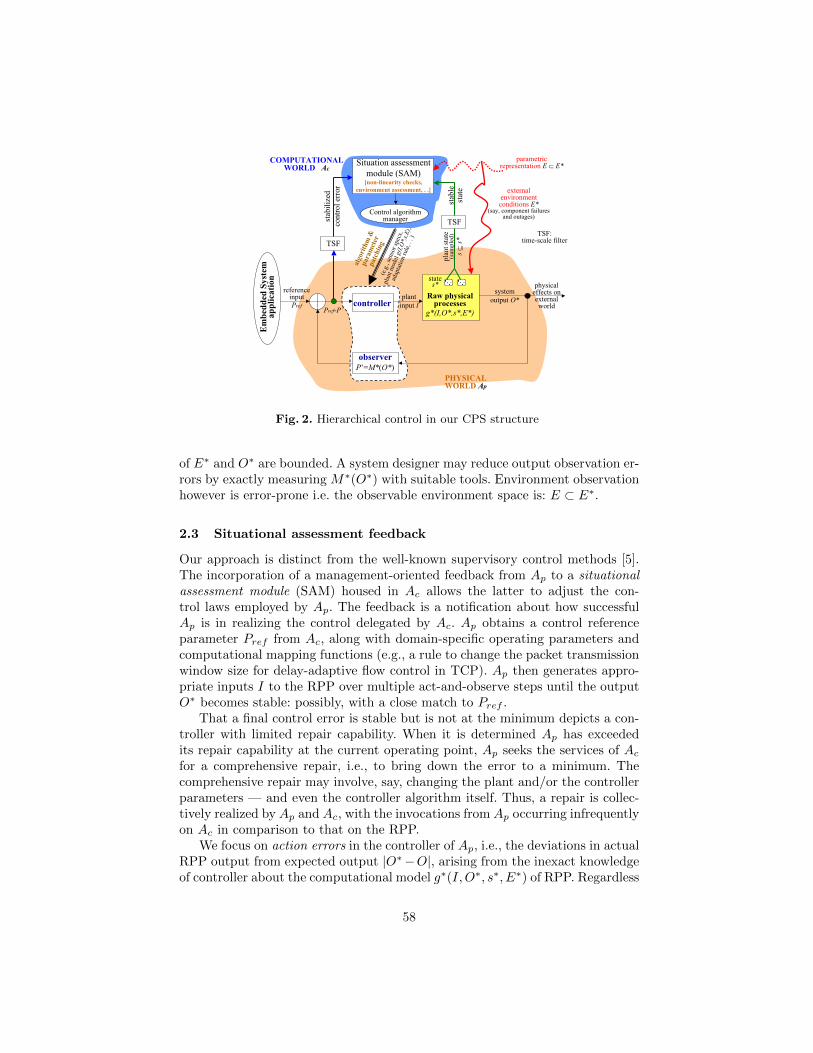
Fig. 2. Hierarchical control in our CPS structure
of E∗ and O∗ are bounded. A system designer may reduce output observation er-rors by exactly measuring M∗(O∗) with suitable tools. Environment observationhowever is error-prone i.e. the observable environment space is: E ⊂ E∗.
2.3 Situational assessment feedback
Our approach is distinct from the well-known supervisory control methods [5].The incorporation of a management-oriented feedback from Ap to a situationalassessment module (SAM) housed in Ac allows the latter to adjust the con-trol laws employed by Ap. The feedback is a notification about how successfulAp is in realizing the control delegated by Ac. Ap obtains a control referenceparameter Pref from Ac, along with domain-specific operating parameters andcomputational mapping functions (e.g., a rule to change the packet transmissionwindow size for delay-adaptive flow control in TCP). Ap then generates appro-priate inputs I to the RPP over multiple act-and-observe steps until the outputO∗ becomes stable: possibly, with a close match to Pref .
That a final control error is stable but is not at the minimum depicts a con-troller with limited repair capability. When it is determined Ap has exceededits repair capability at the current operating point, Ap seeks the services of Ac
for a comprehensive repair, i.e., to bring down the error to a minimum. Thecomprehensive repair may involve, say, changing the plant and/or the controllerparameters — and even the controller algorithm itself. Thus, a repair is collec-tively realized by Ap and Ac, with the invocations from Ap occurring infrequentlyon Ac in comparison to that on the RPP.
We focus on action errors in the controller of Ap, i.e., the deviations in actualRPP output from expected output |O∗−O|, arising from the inexact knowledgeof controller about the computational model g∗(I,O∗, s∗, E∗) of RPP. Regardless
58

of an error-prone or error-free output observation, action errors do occur, i.e.,the output of RPP O∗ as a result of executing an action I may deviate from thecontrollers belief about the effect of I, as captured by the model g(I,O, s, E).An3 error-free output observation, which we assume in this paper, yields anexact measurement of action errors — thereby allowing Ac to precisely evaluatethe efficacy of controller rules/policies implanted in Ap, and install any changestherein.
2.4 Advantages of our approach
The observe-adapt cycle executed by Ap is at the machine-level time-scales per-tinent to the RPP. The operations of Ac occur at much slower time-scales. Theseparation of time-scales in the operations of Ac and Ap makes it easier to as-sert the correctness of application behavior with a high degree of confidence.In TES-based design, the time-scale separation is not easily extractable froma trace-analysis of the state-transitions in application software, which lowersthe designer confidence in making correctness assertions. In this light, our CPS-based modular techniques purport to reduce the overall system development costduring the evolutionary and operational stages of system designs, in the face ofincreasing complexity of system operations (both hardware and software) tomeet the enhanced demands for new and better functionalities.
The patching of Ap from Ac enables the autonomic switching of controlalgorithms (at run-time) as the system operating points change. Ap can be sup-plied by designers with domain-knowledge (such as OEM vendors for in-vehicleelectronic systems and network platform developers for inter-vehicle communi-cations). Ap is designed to be programmable, with appropriate signaling hooks,while meeting the inter-operability requirements. Whereas, the designers of Ac
are software engineers with more expertise on the management functions (in-stead of the domain itself). Some of the computational intelligence in Ap areenabled by new applications. Ap may also realize some of the functions hithertoin the TES-based computational world. The migration is possible due to theavailability of data processing and storage capabilities in the physical compo-nents.
3 Management of distributed intelligent systems
From a service specification standpoint, the system performance, fault-tolerance,and timeliness goals can be unified into a single set of application-level QoSobjectives. How well the application-level QoS specs are met in the presence ofhostile external conditions depicts the dependability of the system.
3 Action errors in a complex system arise as an artifact of system modeling inaccuracy,which are different from the ones caused by software-induced bugs and failures [6].
59

3.1 Failure impact of system components
Given an ensemble of K devices in the infrastructure, Ac chooses N devicesto participate in the algorithm execution of Ap for a collaborative task, where2 ≤ N � K. An example is the reaching of consensus about an event occurrence.The choice of N is tied to an assumption made by Ac that at most fm devicescan fail at run-time and an attacked device exhibits a fault severity of r — where1 ≤ fm < N and 0 < r ≤ 1.0. A failure may be benign or malicious, which maybe (partly) captured in the fault severity parameters.
An intruder potentially targets fa of the K devices for attacks to disruptthe system-level output, where 0 ≤ fa � K. Furthermore, an attacked deviceexhibits a fault severity of r′′, which depicts the probability of misbehavior by anattacked device when an input trigger occurs (r′′ may be quantified in terms ofhow many operations the attacked device performs correctly before respondingmaliciously to an input trigger). The intruder does not have knowledge of system-level algorithm parameters [N, r, fm] (i.e., this information is protected in Ac):where N is the number devices participating in algorithm (2 ≤ N ≤ K), fm isthe assumed number of faulty devices (1 ≤ fm < dN2 e), and r is the assumedaggressiveness of a faulty device (0 < r ≤ 1). So, the intruder randomly targetsthe attacks on fa devices and infuses a fault severity-level of r′′ on an attackeddevice, in the hope of damaging the system output. The choice of [fa, r
′′] isbased on the computational and other assets available at the intruder’s disposalto orchestrate attacks and his/her empirical knowledge about the anticipatedsystem-level damage caused by attacks.
Since [r′′, fa] is not known to Ac, the algorithm designer needs to modelthe intruder’s capability and profile to get a probabilistic estimate of [fa, r
′′].In general, the designer’s decision about [N, r, fm] is based on his (domain-specific) knowledge about the overall system: namely, the operating environmentof infrastructure and the control loops implemented by Ap.
3.2 Managing sensor redundancy and heterogeneity
Resorting to sensor heterogeneity in system measurements interplays with thecontrol functions that rely on the accuracy and timely detection of events. A de-vice D may run different algorithms oa = g(D)a(M), ob = g(D)b(M), · · · on a rawinput data M (sequentially or concurrently), and then extract an accurate infor-mation oa, ob, · · · about an event occurrence therefrom: say, by voting or outlieranalysis on oa, ob, · · ·. Furthermore,D may survive against software errors and/ortargeted attacks on a specific algorithm, say, g(D)a(.), because the other functionsg(D)b(.), · · · may continue running [20]. To survive against severe device-level fail-ures (such as machine crashes and multiple attacks), a spatial replication of thedevice-functions is employed: such as oa = g(D1)a(.), ob = g(D2)b(.), · · ·. Figure 3-(A) illustrates the temporal and spatial redundancy to infuse survivability of thesensing process. If H is the number of heterogeneous devices, the system-leveldesign complexity is O(H2). Figure 3-(B) shows the cost of device replicationfrom a system designer perspective.
60
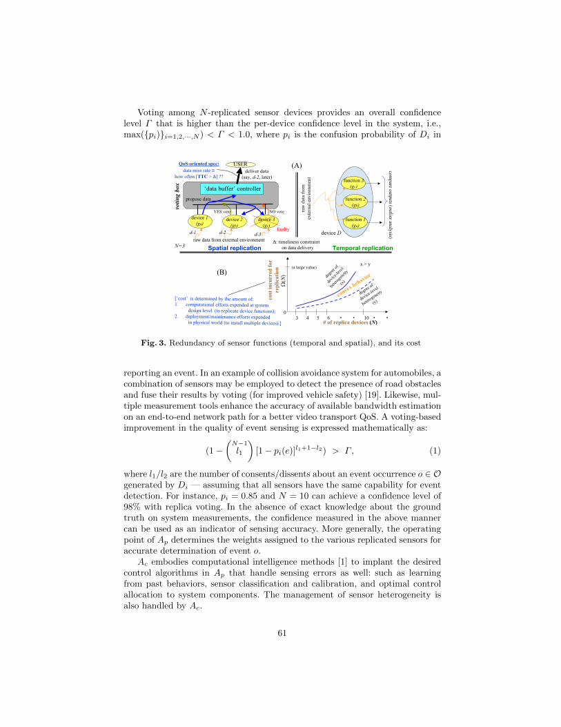
Voting among N -replicated sensor devices provides an overall confidencelevel Γ that is higher than the per-device confidence level in the system, i.e.,max({pi)}i=1,2,···,N ) < Γ < 1.0, where pi is the confusion probability of Di in
raw data from external environment
NO vote
‘data buffer’ controller
USER
device 1
(ga)
voti
ng
bo
x
propose data
device 2
(gb)
d-1 d-2
device 3
(gc)
d-3
YES vote
faulty
QoS-oriented spec:
data miss rate
how often [TTC > ] ??
: timeliness constraint
on data delivery
cost
in
curr
ed f
or
rep
lica
tion
[‘cost’ is determined by the amount of:1. computational efforts expended at system
design level (to replicate device functions);2. deployment/maintenance efforts expended
in physical world (to install multiple devices).] # of replica devices (N)4 5 6 103 . .
0
(a large value)
. .
convex
behavior
(N) de
gree
of
devi
ce-le
vel
hete
roge
neity
(x)
x > y
degree
of
device
-level
hetero
geneit
y
(y)
Spatial replication Temporal replication
(B)
function 1
(ga)
function 2
(gb)
function 3
(gc)
device D
raw
dat
a fr
om
exte
rnal
en
vir
on
men
t
com
pare o
utp
uts (o
utlier an
alysis)
(A)deliver data
(say, d-2, later)
N=3
Fig. 3. Redundancy of sensor functions (temporal and spatial), and its cost
reporting an event. In an example of collision avoidance system for automobiles, acombination of sensors may be employed to detect the presence of road obstaclesand fuse their results by voting (for improved vehicle safety) [19]. Likewise, mul-tiple measurement tools enhance the accuracy of available bandwidth estimationon an end-to-end network path for a better video transport QoS. A voting-basedimprovement in the quality of event sensing is expressed mathematically as:
(1−(
N−1l1
)[1− pi(e)]l1+1−l2) > Γ, (1)
where l1/l2 are the number of consents/dissents about an event occurrence o ∈ Ogenerated by Di — assuming that all sensors have the same capability for eventdetection. For instance, pi = 0.85 and N = 10 can achieve a confidence level of98% with replica voting. In the absence of exact knowledge about the groundtruth on system measurements, the confidence measured in the above mannercan be used as an indicator of sensing accuracy. More generally, the operatingpoint of Ap determines the weights assigned to the various replicated sensors foraccurate determination of event o.
Ac embodies computational intelligence methods [1] to implant the desiredcontrol algorithms in Ap that handle sensing errors as well: such as learningfrom past behaviors, sensor classification and calibration, and optimal controlallocation to system components. The management of sensor heterogeneity isalso handled by Ac.
61

4 Data aggregation in on-tree nodes
In this section, we describe the high level aggregation operations carried out bythe on-tree nodes4. There are two reasons for the on-tree aggregation of eventsas they surface, instead of aggregating all the events at the root node. First, itenhances the scalability of event reporting system when large amounts of dataare collected. Second, it entails a faster reaction to the events by overlay nodes assoon as a composite situation emerges that warrants an action (e.g., respondingto traffic congestion events).
See Figure 4 for an illustration of the communication structure event noti-fication. The overlay node at leaf point of the event aggregation tree maintainsinformation about the capability of devices serviced by that node (such as encod-ing format, CPU speed, and display size). The node may, for instance, transcodethe multimedia data describing an event for device-level rendering. The on-treeaggregation capabilities of overlay nodes is quite useful for vehicular networks(instead of doing only at end-point nodes).
4.1 Aggregation using syntactic rules
Let Θ1 and Θ2 be the confidence intervals of the data delivered at an overlaynode O from its two downstream segments. With only a syntactic processing ofthe two distinct events, a confidence measure associated with the combined datasent by O to its upstream node is: min({Θ1, Θ2}).
Similarly, other types aggregation operators can be implemented in O such asaddition, maximum, average, median, set union & intersection, selection, and thelike. For instance, the congestion reports from two segments along the plannedroute of a car with projected delays d1 and d2 will simply lead to an estimate ofthe combined delay as d1 +d2 in traversing this route. Scalability considerationsrequire that the syntactic composition operators satisfy the commutativity andassociativity properties [17]. These properties allow an efficient examination ofthe events arriving asynchronously from various downstream nodes (by reducinginter-event synchronization delays).
An aggregation of events at various nodes in the tree typically affects thetime-scale of changes in the resulting macro-level data. An example is to deter-mine if there is a sustained packet loss in a multi-hop network (with k hops),based on the spatially separated per-hop measurements. The end-to-end loss is:
[1−k∏
i=1
(1− li)],
where li is the measured packet loss in ith hop. Since the ’loss composition’operator combines a set of fluctuating per-hop loss rates with independent modes
4 The data aggregation functions in on-tree overlay nodes and the communicationfunctions between overlay nodes can be structured independent of that in the ad-hoc network segments at leaf nodes.
62

WIRED CLIENTDEVICES
(e.g., metroresidential area)
even
tso
urc
e A
WIRELESSCLIENT DEVICE
ON
ON
ON
ON
ON
ON
xDSLnetwork
ON
wired linkswireless access links
path segment in wide-areadistribution tree
event data flows (original)(video, audio, image)
transcoded
satellite link
WIR
EL
ES
S
CL
IEN
T D
EV
ICE
S
subgroup-l1
subgroup-m1
subg
rou
p-n1
subgroup-p1
l
p
m
n
userde-subscribesfrom source B
ON: multicast-capable overlay node
WIRELESSCLIENT DEVICES
subgroup-m2
eventsource B
ON
(maintains deviceconfiguration data)
Tree termination point atreceiver proxy nodes l,m,n,p
Fig. 4. Communication structure for event aggregation
at any given time, the end-to-end loss rate varies with a time-scale as determinedby the highest mode in the per-hop loss rates. A spatial scale of changes may alsobe associated with event aggregations — such as the vehicular traffic congestionon a given route being the combination of the reported congestion levels invarious stretches of roads along that route.
A domain-specific interpretation of the events in different regions cannot beadequately captured with the standard mathematical operators of aggregation— as argued in [2]. For example, the effect of a vehicle accident in one regionon traffic congestions in the adjoining regions cannot be expressed through sim-ple syntactic connectives. This motivates the need for a semantic knowledge ininterpreting events.
4.2 Aggregation using semantic knowledge
Vehicular network applications often require abstracted measurements of thediverse environment phenomena (or events) in various geographic regions. Thesemeasurements need to be interpreted using a semantic relationship between theevents (which may take into account the weak consistency and the temporalcorrelation among events [18]). Typically, the confidence level in the reporting ofa combined event can be increased with a semantic knowledge that interconnectsthe two independently reported events.
As an example, consider the detection of a plane (in terms of speed andlocation) by the devices in region 1 followed by the detection of a plane by thedevices in an adjacent region 2 after a certain time interval T . If the geographicdistance between regions 1 and 2 depicts a flight time close to T at the givenspeed, then it is highly likely that the object detected in regions 1 and 2 refersto the same plane. So, when the detection reports from regions 1 and 2 arrive
63
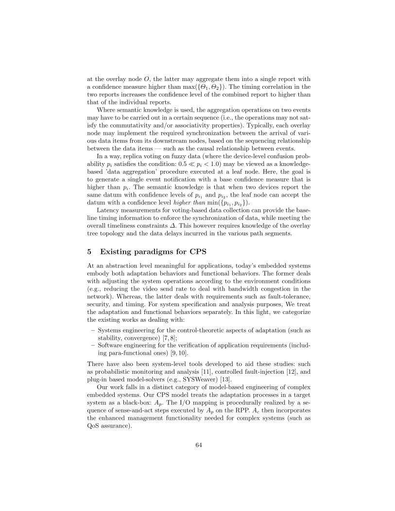
at the overlay node O, the latter may aggregate them into a single report witha confidence measure higher than max({Θ1, Θ2}). The timing correlation in thetwo reports increases the confidence level of the combined report to higher thanthat of the individual reports.
Where semantic knowledge is used, the aggregation operations on two eventsmay have to be carried out in a certain sequence (i.e., the operations may not sat-isfy the commutativity and/or associativity properties). Typically, each overlaynode may implement the required synchronization between the arrival of vari-ous data items from its downstream nodes, based on the sequencing relationshipbetween the data items — such as the causal relationship between events.
In a way, replica voting on fuzzy data (where the device-level confusion prob-ability pi satisfies the condition: 0.5� pi < 1.0) may be viewed as a knowledge-based ’data aggregation’ procedure executed at a leaf node. Here, the goal isto generate a single event notification with a base confidence measure that ishigher than pi. The semantic knowledge is that when two devices report thesame datum with confidence levels of pi1 and pi2 , the leaf node can accept thedatum with a confidence level higher than min({pi1 , pi2}).
Latency measurements for voting-based data collection can provide the base-line timing information to enforce the synchronization of data, while meeting theoverall timeliness constraints ∆. This however requires knowledge of the overlaytree topology and the data delays incurred in the various path segments.
5 Existing paradigms for CPS
At an abstraction level meaningful for applications, today’s embedded systemsembody both adaptation behaviors and functional behaviors. The former dealswith adjusting the system operations according to the environment conditions(e.g., reducing the video send rate to deal with bandwidth congestion in thenetwork). Whereas, the latter deals with requirements such as fault-tolerance,security, and timing. For system specification and analysis purposes, We treatthe adaptation and functional behaviors separately. In this light, we categorizethe existing works as dealing with:
– Systems engineering for the control-theoretic aspects of adaptation (such asstability, convergence) [7, 8];
– Software engineering for the verification of application requirements (includ-ing para-functional ones) [9, 10].
There have also been system-level tools developed to aid these studies: suchas probabilistic monitoring and analysis [11], controlled fault-injection [12], andplug-in based model-solvers (e.g., SYSWeaver) [13].
Our work falls in a distinct category of model-based engineering of complexembedded systems. Our CPS model treats the adaptation processes in a targetsystem as a black-box: Ap. The I/O mapping is procedurally realized by a se-quence of sense-and-act steps executed by Ap on the RPP. Ac then incorporatesthe enhanced management functionality needed for complex systems (such asQoS assurance).
64
6 Case study: Vehicular traffic management
Vehicular networks often consist of computational devices, i.e., ECUs, that col-lect data representing the road traffic conditions and then generate traffic alertsfor use by drivers. The data may include road traffic volume, terrain scenarios(e.g., hill tracks, slippery road), weather conditions, and vehicle motion tracking(e.g., car speed, inter-car spacing). These data, some of which constitute theexternal environment parameters E, are collected by various sensors mountedon the cars and the roadside, and then processed to generate corrective actions:say, traffic alerts and traffic re-routing.
6.1 IPW in vehicular traffic-flow system
The physical world is the road infrastructure itself, through which vehicular traf-fic flows. The topological parameters of infrastructure describe the interconnec-tion of various road segments: such as the number of lanes along a road segment,posted speed limits, and traffic signal intersections, and the merge/branch pointsof different road segments. Such a road infrastructure is augmented with trafficmonitoring and alert functions to enable an intelligent behavior:
1. Drivers may be notified of prevailing or anticipated congestion levels (viaroadside displays, radio broadcasts, and SMS to phone subscribers);
2. Road crew may reduce congestion by opening and/or closing selected roadsegments and lanes (with a quick setup of dividers and road-blocks)5.
Infusing a capability for congestion notification and (limited) relief is based oncomputational models of the traffic-flow system, as executed by the local trans-portation hubs of crews that collectively manage the road infrastructure.
Given the above delineation of IPW functions, supervisory control functionscan then be assigned to other units in the traffic-flow system higher in the man-agement hierarchy: such as regional transportation centers. The latter, whichconstitutes the ICW, enforces policy decisions on traffic flows such as road clo-sures and traffic prioritization. The ICW takes cognizance of the effectivenessof current infrastructure in adapting to various congestion levels, and takes re-covery actions therein (e.g., authorizing the conversion of a two-way lane toa one-way lane). Such computational intelligence functions of ICW supply theconfiguration inputs to the IPW functions that invoke the traffic-flow system.
The traffic data collected is prone to errors for two reasons: First, the pro-cessing algorithms in sensor devices may often have only limited capabilities,and also exhibit diversity due to vendor-specific implementations. The trafficreports generated therein may be fuzzy, providing an imprecise representationof the ground truth: namely, the congestion state. Second, some of the devicesmay be maliciously faulty mis-reporting the traffic flow. In such a setting, repli-cation of devices and voting on the traffic data collected by them enhances thetrust-worthiness of congestion reports generated.
5 Closing a road or lane may sometime reduce congestion if the traffic merge from theoffending road/lane onto a main road creates local vortex effects at the intersection.
65

In terms of our CPS-based design approach, the voting/fusion component isa part of the observer module M(O) which maps the traffic reports from varioussources onto composite descriptors of congestion events. These event notificationsare annotated with quantifiers that depict the quality of congestion reports q asa percentile scale: i.e., q ∈ (0, 1). Figure 5-(a) illustrates how the event-reportaccuracy q impacts the decision-making process of controller module C.
6.2 Improving the accuracy of traffic reports
We employ k-out-of-N consensus voting [14] to decide on an accurate congestionreport, where N is the number of replicas reporting traffic data and k is thelevel of consensus needed among replicas. A higher k yields a better accuracyof the congestion report, with the parameter N set to meet the condition: 1 <k ≤ N . This is a case of reaching approximate agreement in sensor data fusionapplications [15].
Consider a case of traffic monitoring on roads with the sensing devices mountedon police vehicles. One device may report a 80% traffic congestion on the road,whereas, another device may report a 75% congestion. The difference may arisein their traffic sampling rates and observation intervals. Besides, a malicious in-truder device that poses as a police vehicle may report a traffic congestion whenthere is none. In the presence of such error-prone traffic reports, a central moni-toring station should be able to take adequate measures to relieve the congestion— such as controlling the traffic inflow into the congested area by diverting thetraffic in the upstream feeder roads. Here, a control measure taken based onincorrect reports can lead to traffic chaos — such as admitting more traffic onthe feeder roads when a mis-reported congestion is acted upon by the monitor-ing station. Figure 5-(b) illustrates the role of replica voting in improving theaccuracy of traffic reports.
With replica voting as the building-block, a data fusion mechanism based onsemantic composition of the traffic reports from different regions may be em-ployed to further improve the quality of inference about congestion. The datafusion may be based on tree-structured overlays set up over a vehicular network[16]. In a tree overlay, the root node is attached to a data dissemination stationand the leaf nodes are attached to the data collection devices in different ge-ographic regions (similar to [17]). The fusion architecture allows incorporatingtwo complementary functionalities: i) sanitization of data collection by votingamong replicated devices at the leaf nodes, and ii) secure propagation of thesanitized data upstream towards the root node for control actions. An interme-diate node, often attached to a stable station (e.g., a police control vehicle, anairborne platform), may also carry out aggregation functions on the data arriv-ing from its downstream tree segments and then forwarding the aggregated dataupstream. Where necessary, the intermediate nodes may also be equipped withfunctions to initiate (limited) control actions in the local regions.
Event quality q is a parametric input to the computational model executedby the controller C. Thereupon, C assimilates the parameter q as part of its
66

notify(1,`not_detected’)
notify(4,`detected’)
notify(3,
`not_detected’)
pre-processdata
start of voting
DETECTED
process data
from sensor units
decide oncongestion relief
notify(2,`detected’)
notify(5,`detected’)
falsenegative !!
maximum possible# of faulty sensors fm=1
congestion inference
trafficsensor 3(faulty)
trafficsensor 2
trafficsensor 5
RawtransportationInfrastructure
(roads & lanes,intersections,
traffic rules, . .)traffic monitor
car trafficout-flow
X=congestionreport: M( )
TRAFFICCONTROLLER C relief
actions
congestionreport [X,q]
car trafficin-flow
supervisory module (ICW)parameter plug-in [N,k,B]
tra
ffic
scen
ari
o
topological modelof infrastructure
IPW
q
(b)
(a)
transportationmanagement center(implements controller C)
votingapparatus
trafficsensor 4
trafficsensor 1
process report
TIME
enforce integrityof `data delivery’
Fig. 5. M & C in vehicular traffic management
decision-making on the traffic management actions6. Typically, the degree ofsensor replication N and the consensus level k for voting on traffic data are con-trollable parameters, with 1 < k ≤ N . While improving the accuracy of trafficreports, a higher k lowers the time to generate a report due to the increased par-allelism among sensor units but increases the network bandwidth consumptionB to exchange synchronization messages.
The choice of [N, k,B] is aided by a calibration of the sensors vis-a-vis theirevent reporting quality and a computational model of the voting sub-systemtherein. The calibration data is maintained by the ICW for dynamically loadinginto the IPW. The parameter patching enables IPW to reconfigure its operationsunder various environment conditions.
7 Conclusions
As embedded systems become complex, there is a need to explicitly incorporatediverse physical computing systems (both hardware and software) in a coherentabstraction. Removing the explicit hardware-centric boundaries as part of thecurrently prevalent definitions of an embedded system, our paper introduced aconcrete notion of intelligent physical world (IPW), and an intelligent computa-tional world (ICW) therein, as the modules of an embedded system.
6 In a multi-agent based realization of C, q is viewed as the belief probability of anagent about the existence of a reported congestion. With epistemic reasoning aboutthe belief states of agents, a traffic control action over different geographic regionscan be realized by various agents with a certain confidence level. Study of how theaccuracy parameter q impacts traffic flow-related decisions of C, and the underlyingepistemic reasoning process, is deferred as a future work.
67

The paper described the software engineering issues in orchestrating a har-monious co-existence of the IPW and ICW. With the aid of a software structuralmodel of a CPS, the paper studied a complex network application: viz., vehiculartraffic congestion monitoring in a transportation network, through the prism ofICW-IPW partitioning.
The advantages of our CPS-style structure of an application are that it re-duces the development cost of distributed control software via software reuseand modular programming. The CPS-style structure also enables easier systemevolutions in the form of adding and/or modifying the controller functionalitiesin applications without weakening the software correctness goals.
References
1. R. C. Eberhart and Y. Shi. Computational Intelligence. In chap. 2, ComputationalIntelligence: Concepts to Implementations, Morgan Kaufman Publ, 2007.
2. S. Kabadayi, A. Pridgen, and C. Julien. Virtual Sensors: Abstracting Data fromPhysical Sensors. Tech. Rep. 2006-01, Univ. of Texas Austin, 2006.
3. F. S. Hillier and G. J. Lieberman. ”Non-linear Programming” and ”Meta-heuristics”. Chap. 12, 13, Introduction to Operations Research, McGraw-Hill publ.(8th ed.), pp.547-616, 2005.
4. J. Love, J, Jariyasunant, E. Pereira, M. Zeenaro, K. Hedrick, C. Kirsch, and R.Sengupta. CSL: A Language to Specify and Re-specify Mobile Sensor NetworkBehaviors. In proc. RTAS’09, 2009.
5. Y. Diao, J. L. Hellerstein, G. Kaiser, S. Parekh, and D. Phung. Self-Managing Sys-tems: A Control Theory Foundation. In IBM Research Report, RC23374 (W0410-080), Oct.2004.
6. N. G. Leveson. Software Challenges in Achieving Space Safety. In Journal of theBritish Inter-Planetary Society, 2009.
7. B. Li, K. Nahrstedt. A Control-based Middleware Framework for Quality of ServiceAdaptations. In IEEE JSAC, 17(9), Sept.1999.
8. C. Lu, Y. Lu, T. F. Abdelzaher, J. A. Stankovic, S. H. Son. Feedback Control Ar-chitecture and Design Methodology for Service Delay Guarantees in Web Servers.In IEEE TPDS, 17(7), Sept. 2006.
9. I. Schaefer and A. P. Heffter. Slicing for Model Reduction in Adaptive EmbeddedSystems Development. In Workshop on Software Engineering for Adaptive andSelf-managing Systems (SEAMS), 2008.
10. J. Yi, H. Woo, J. C. Browne, A. K. Mok, F. Xie, E. Atkins, and C. G. Lee. In-corporating Resource Safety Verification to Executable Model-based Developmentfor Embedded Systems. In IEEE Real-time and Embedded Technology and Appli-cations Symp., 2008.
11. T. Mikaelian, B. C. Williams, and M. Sachenbacher. Probabilistic Monitoringfrom Mixed Software and Hardware Specifications. In Proc. ICAP’05 Workshopon Verification and Validation of Model-based Planning and Scheduling Systems,2005.
12. P. E. Lanigan, P. Narasimhan, T. E. Fuhrman. Experiences with a CANoe-basedFault Injection Framework for AUTOSTAR. In IEEE/IFIP Conf. on DependableSystems and Networks (DSN’10), 2010.
68

13. A. Rowe, G. Bhatia, and R. Rajkumar. A Model-Based Design Approach for Wire-less Sensor-Actuator Networks. In proc. workshop on Analytic Virtual Integrationof Cyber-Physical Systems (AVICPS’10), Nov. 2010.
14. M. V. Erp, L. Vuurpijl, and L. Schomaker. An overview and comparison of votingmethods for pattern recognition. In proc. IEEE Intl. Workshop on Frontiers inHandwriting Recognition (WFHR02), 2002.
15. R. R. Brooks and S. Iyengar. Chap. on Sensor Fusion and Approximate agreement.In Multisensor Data Fusion, Prentice-Hall Publ., 1998.
16. K. Ravindran. Replica Voting based Architectures for Reliable Data Disseminationin Vehicular Networks. In proc. Intl. Conf. on Telecommunications for IntelligentTransport Systems (ITST-2011), IEEE, St. Petersburg (Russia), Aug. 2011.
17. R. Stadler, F. Wuhib, M. Dam, and A. Clemm. Decentralized Computation ofThreshold-crossing Alerts. In proc. conf. on Distributed Systems: Operations andManagement, IEEE/IFIP, Barcelona (Spain), Oct. 2005.
18. W. Hu, A. Misra, and R. Shorey. CAPS: Energy-Efficient Processing of Continu-ous Aggregate Queries in Sensor Networks. In proc. 4th Intl. conf. on PervasiveComputing and Communications, IEEE-PerCom’06, pp.190-199, June 2006.
19. D. A. Amditis and et al. Multiple Sensor Collision Avoidance System for Automo-tive applications using an IMM approach for obstacle tracking. In proc. Fusion’02,Intl. Society of Information Fusion, 2002.
20. S. Forrest, A. Somayaji, and D.H. Ackley. Building Diverse Computer Systems. Inproc. 6th Workshop HotOS-VI, IEEE, 1997.
69