cxsm tilt/lift combo harness routing q7me - sunrise medical
TRANSCRIPT

Rearshroud
Plate
1
Fasteners
FastenersLift/Tiltmodule cover
1a
A
1 5 132
4 - 14
Top row 2
Bottomrow
BUS
A. Preparing for installation: 1. Remove the rear shroud by detaching the Velcro® at the sides and lifting off from the blocks at the top of the frame. 2. Using the wire cutter cut the cable-tie (A) holding the wires to the plate, Detail 1a. 3. Lift the module up 4" or more to access the base harness. If you are able to do this then you can skip steps 7 - 9. 4. Unplug all the wires from the top and bottom rows of the CxSM. Ensure that the labels on the wires are not disturbed. Fig 2. 5. Use the 3mm hex key to remove the cover from the Lift/Tilt module. Fig 3. Save screws. 6. Cut cable-tie on Fig 7, unplug tilt connector (shown in Fig 7). 7. Remove cable track by removing the two screws, Fig 5. 8. Fish the connector from the top and unplug. 9. Plug in the new lift connector. Power up the control and lift the seat 3 - 4" for access. Then unplug the new lift connector. 10. Cut cable-tie and unplug the rest of track harnesses, Fig 13. 11. Remove harnesses.
B. Installing the Harness: 1. Route cables in the harness track so that the Bus cable is on the left and the actuator harness is on the right , Fig 4. 2. Route actuator harness under the actuator motor, Fig 6. 3. Cable-tie the harness to the track, Fig 5. 4. Plug in tilt connector and cable-tie harness. Fig 7. Put the cover back on, Fig 3, using saved screws. Torque to 2.3 - 2.7 ft-lbs (3.1 - 3.7Nm). 5. Plug the bottom row of harnesses into the CxSM first in this order: Leg Extend (white label) first, Leg Lift (yellow label) second, Lift (green label) third, Tilt (purple label) fourth, and Recline (red label) last, Fig 8 & 10. 6. Plug in the inhibit harnesses (top row) in this order: Recline (label 1) first, Tilt or Tilt/Lift (label 2) second, and Leg (label 3) last, Fig 9. Inhibit 6 & 8 are optional. Make sure the graphic or number label on the wires matches the corresponding graphic or number labels on the CxSM. Note- Not all chairs will have the same amount of wires. Yours may differ from the one shown. 7. Ensure that the wires are tucked in out of the way, Fig 11, 12, 13, & 14. 8. Use supplied cable-tie (A) to secure wires to the plate. Do not cable-tie Recline Position 1 top row. Detail 1a and Fig 12&13. 9. Reinstall the rear shroud by lining up the shroud to the blocks on the top of the frame and then pushing into the Velcro® at the sides.
Tools needed: 1. Wire cutter 3. Screw driver 2. 3mm Hex key 4. Torque wrench
Included Parts: 1. 1 ea Track Harness 2. 4 ea Cable-tie
CxSM
3
7
CxSM TILT/LIFT COMBOHARNESS ROUTING Q7ME
Please read these instructions carefully before beginning the installation. Failure to understand andfollow installation instructions may result in injury to installer and/or end user and may void the warranty.If you have any questions call Sunrise Medical Technical Support at 800-333-4000.
5/18 248016 Rev. A Pg. 1 of 4©2018 Sunrise Medical (US) LLC
4
5
7
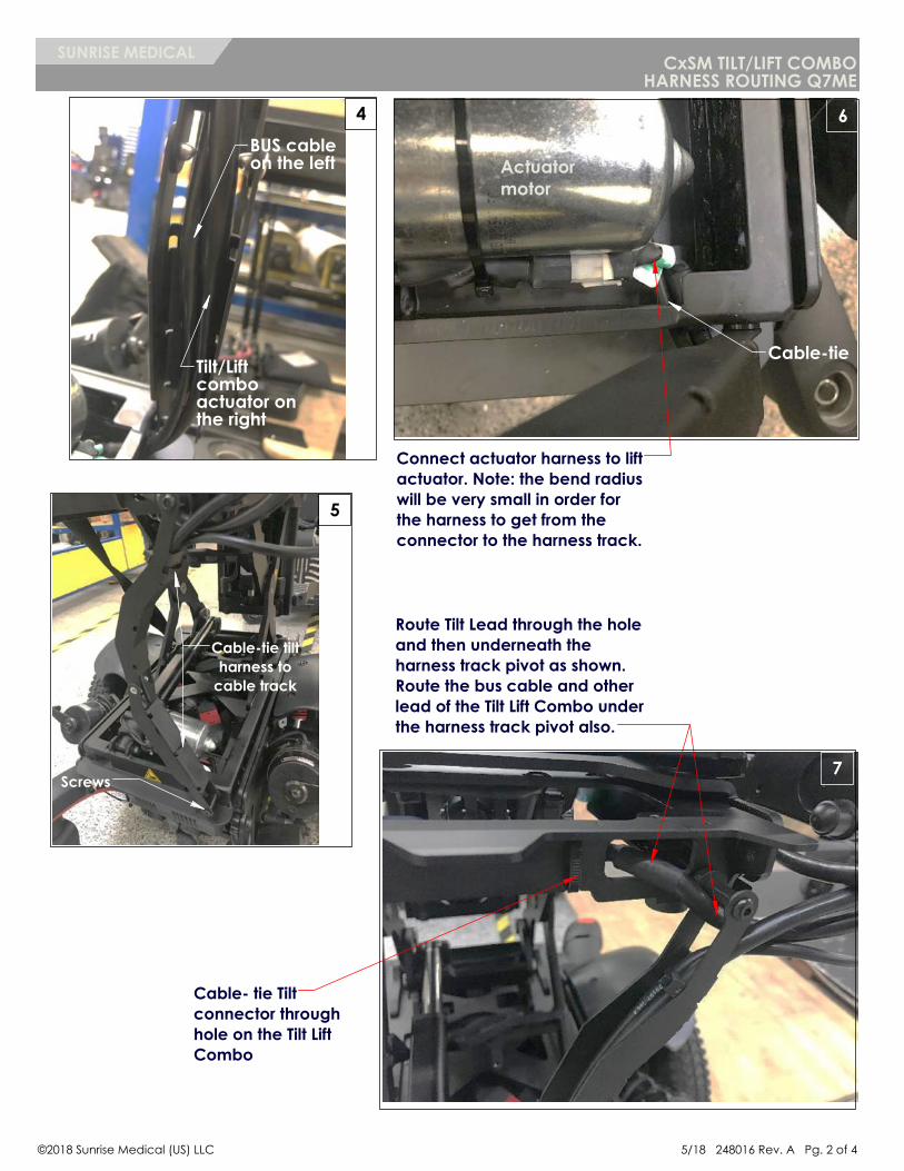
BUS cableon the left
Route Tilt Lead through the hole and then underneath the harness track pivot as shown. Route the bus cable and other lead of the Tilt Lift Combo under the harness track pivot also.
Cable-tie tiltharness to
cable track
Tilt/Liftcomboactuator on the right
Cable- tie Tilt connector through hole on the Tilt Lift Combo
6
Connect actuator harness to lift actuator. Note: the bend radius will be very small in order for the harness to get from the connector to the harness track.
Actuatormotor
Screws
Cable-tie
CxSM TILT/LIFT COMBOHARNESS ROUTING Q7ME
SUNRISE MEDICAL
©2018 Sunrise Medical (US) LLC 5/18 248016 Rev. A Pg. 2 of 4

11
10
9
8
RECLINE (Red)
TILT (Purple)
LIFT (Green)
LEG LIFT (Yellow)
LEG EXTEND (White)
RECLINE (1)
TILT or TILT/LIFT (2)LEGS (3)
Recline (1)
12
Route Recline Actuator Harness behind actuator and below CxSM. Connect to actuator port 1.Actuator
Route Recline Potentiometer Harness behind actuator and below CxSM. Connect to inhibit.
Cable-tie all component harnesses, except recline inhibit, along with the actuator harness together to prevent actuator harness from being pinched.
CxSM TILT/LIFT COMBOHARNESS ROUTING Q7ME
SUNRISE MEDICAL
5/18 248016 Rev. A Pg. 3 of 4©2018 Sunrise Medical (US) LLC

Cable- tie tilt/lift combo harness with controller harness and any other harness from components with cable-tie through holes on controller bracket.
Wrap tilt/ lift combo harness with harness to controller module with spiral wrap. Stop wrap on controller harness at connector.
Route Tilt/ Lift Combo harness out of module.
Make sure there is enough of a service loop before putting on the shroud. The connectors to the controller module should be completely exposed when the shroud is installed.
13
14
C. Inspect: 1. Seating system to ensure all wire harnesses are out of the way and are not getting pinched. 2. Seating system to verify that the harnesses are not put under tension in any position. 3. Ensure that the cable-ties are not so tight that they deform cable jackets. 4. Where possible cables should be protected and hidden by shrouds. 5. Use torque wrench to check torque values.
CxSM TILT/LIFT COMBOHARNESS ROUTING Q7ME
SUNRISE MEDICAL
Sunrise Medical 2842 N. Business Park Ave Fresno, CA 93727 USAIn Canada (800) 263-3390
©2018 Sunrise Medical (US) LLC5/18 248016 Rev. A Pg. 4 of 4
Customer service: 800.333.4000or visit www.SunriseMedical.com