customer training workshop: introduction to psoc 4 featuring …€¦ · 2:20 (45 min) 25 lab #3:...
TRANSCRIPT

Introduction to PSoC 4 Customer Training Workshop with PSoC 4 M-Series001-96819 Owner: JFMD (JHNW, GOPA, GHR, DSG, GMRL, JMY)
Rev ** Tech lead: PMAD
Replace Legacy 8-/16-Bit Platforms With the World’s
Most Flexible 32-Bit ARM® Cortex®-M0 One-Chip Solution
Customer Training Workshop:
Introduction to PSoC 4
Featuring the PSoC 4 M-Series Pioneer Kit

Introduction to PSoC 4 Customer Training Workshop with PSoC 4 M-Series 2001-96819 Owner: JFMD
Rev ** Tech lead: PMAD
Workshop Objectives
By the end of this workshop, you will
Understand the PSoC® 4 Programmable System-on-Chip architecture
Learn how to use Cypress’s solutions and integrated development environment (IDE) to implement:
Digital designs with PSoC 4
CapSense® touch-sensing user interface designs with PSoC 4
One-chip, sensor-based system designs with PSoC 4

Introduction to PSoC 4 Customer Training Workshop with PSoC 4 M-Series 3001-96819 Owner: JFMD
Rev ** Tech lead: PMAD
Time Page Topic
0:00 (15 min) 4 Set Up and Install Software
0:15 (10 min) 5 PSoC Terms
0:25 (15 min) 9 Demo #1: PSoC Creator™1 Overview
0:40 (30 min) 11 Lab #1: PSoC 4 M-Series2 Pioneer Kit Overview and Blinking LED
1:10 (20 min) 14 PSoC 4 Architecture
1:30 (10 min) 20 Demo #2: Micrium µC/Probe3 Overview
1:40 (10 min) 22 Session Break
1:50 (30 min) 23 Lab #2: Digital System Design
2:20 (45 min) 25 Lab #3: CapSense Touch-Sensing Design
3:05 (45 min) 30 Lab #4: Sensor-Based System Design
3:50 (10 min) 35 Wrap-up
4:00 End of workshop
Workshop Agenda
1 PSoC 3, PSoC 4 and PSoC 5 Integrated Design Environment (IDE) software that installs on your PC2 A PSoC 4 with up to 128KB flash, 55 I/Os, Direct Memory Access, 2x CAN, 12 Programmable Analog Blocks and 16 Programmable Digital Blocks3 A firmware development tool by Micrium that installs on your PC and helps debug system designs

Introduction to PSoC 4 Customer Training Workshop with PSoC 4 M-Series 4001-96819 Owner: JFMD
Rev ** Tech lead: PMAD
Required software and initial steps
Copy the contents of the provided USB drive onto your laptop and install the software listed in the table below
Follow the on-screen instructions to complete the installation in approximately 15 minutes
Required hardware:
PSoC 4 M-Series3 Pioneer Kit (CY8CKIT-044), shown at right
Raise your hand if you need help!
Set Up and Install Software
Software Version File Name
PSoC Creator1 Installer 3.2 “PSoCCreatorSetup_3.2_es100”
Micrium µC/Probe2 3.5 (or newer) “Micrium-uC-Probe-Setup-Release-3.5.15.300.exe”
PSoC 4 M-Series3 Pioneer Kit Installer 1.0 (or newer) “CY8CKIT044PIONEERKITSetupOnlyPackage_RevSS.exe”
PSoC 4 M-Series3 Lab Exercise Files 1.0 “PSoC_4_M-Series_Workshop.zip”
1 PSoC 3, PSoC 4 and PSoC 5 Integrated Design Environment (IDE) software that installs on your PC2 A firmware development tool by Micrium that installs on your PC and helps debug system designs3 A PSoC 4 with up to 128KB flash, 55 I/Os, Direct Memory Access, 2x CAN, 12 Programmable Analog
Blocks and 16 Programmable Digital Blocks

Introduction to PSoC 4 Customer Training Workshop with PSoC 4 M-Series 5001-96819 Owner: JFMD
Rev ** Tech lead: PMAD
PSoC Terms
PSoC
PSoC is the world’s only programmable embedded system-on-chip integrating an MCU core, Programmable Analog Blocks,
Programmable Digital Blocks, Programmable Interconnect and Routing1 and CapSense
Programmable Analog Block
A hardware block that is configured using PSoC Components2 to create
Analog Front Ends (AFEs), among other capabilities
Includes Continuous Time Blocks, analog-to-digital converters (ADCs) and
digital-to-analog converters (DACs)
Continuous Time Block (CTB)
A Programmable Analog Block that is used to implement continuous time
analog circuits such as opamps and programmable gain amplifiers (PGAs)
Programmable Digital Block
A hardware block that is configured using PSoC Components2 to implement
custom digital peripherals and glue logic
Includes Universal Digital Blocks, Serial Communication Blocks (SCBs) and TCPWMs3
Universal Digital Block (UDB)
A PSoC Programmable Digital Block that contains: two programmable logic devices (PLDs), one programmable data path with
an arithmetic logic unit (ALU), one status register and one control register
Configured in PSoC Creator4 using PSoC Components2, or the graphical state machine editor or Verilog code
Serial Communication Block (SCB)
A PSoC Programmable Digital Block that is configurable as a UART, SPI or I2C interface
Illustration of a PSoC Device Being Flexibly
Configured by Plugging in PSoC Components2
1 Connects the Programmable Analog Blocks, Programmable Digital Blocks and I/Os 3 Timer, counter, pulse-width modulator (PWM)2 Free embedded ICs represented by an icon in PSoC Creator software 4 PSoC 3, PSoC 4 and PSoC 5 Integrated Design Environment (IDE) software that installs on your PC
Introduction to PSoC 4 Customer Training Workshop with PSoC 4 M-Series 6001-96819 Owner: JFMD
Rev ** Tech lead: PMAD
PSoC Terms
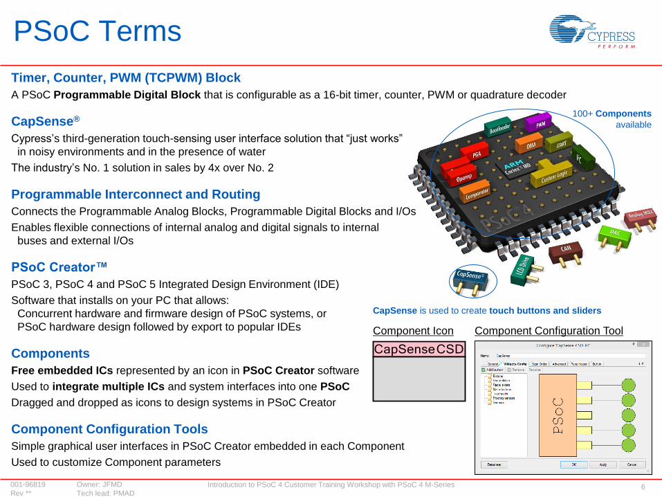
Timer, Counter, PWM (TCPWM) Block
A PSoC Programmable Digital Block that is configurable as a 16-bit timer, counter, PWM or quadrature decoder
CapSense®
Cypress’s third-generation touch-sensing user interface solution that “just works”
in noisy environments and in the presence of water
The industry’s No. 1 solution in sales by 4x over No. 2
Programmable Interconnect and Routing
Connects the Programmable Analog Blocks, Programmable Digital Blocks and I/Os
Enables flexible connections of internal analog and digital signals to internal
buses and external I/Os
PSoC Creator™
PSoC 3, PSoC 4 and PSoC 5 Integrated Design Environment (IDE)
Software that installs on your PC that allows:
Concurrent hardware and firmware design of PSoC systems, or
PSoC hardware design followed by export to popular IDEs
Components
Free embedded ICs represented by an icon in PSoC Creator software
Used to integrate multiple ICs and system interfaces into one PSoC
Dragged and dropped as icons to design systems in PSoC Creator
Component Configuration Tools
Simple graphical user interfaces in PSoC Creator embedded in each Component
Used to customize Component parameters
CapSense is used to create touch buttons and sliders
Component Icon Component Configuration Tool
100+ Components
available
Introduction to PSoC 4 Customer Training Workshop with PSoC 4 M-Series 7001-96819 Owner: JFMD
Rev ** Tech lead: PMAD
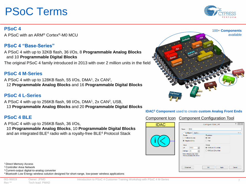
PSoC 4
A PSoC with an ARM® Cortex®-M0 MCU
PSoC 4 “Base-Series”
A PSoC 4 with up to 32KB flash, 36 I/Os, 8 Programmable Analog Blocks
and 10 Programmable Digital Blocks
The original PSoC 4 family introduced in 2013 with over 2 million units in the field
PSoC 4 M-Series
A PSoC 4 with up to 128KB flash, 55 I/Os, DMA1, 2x CAN2,
12 Programmable Analog Blocks and 16 Programmable Digital Blocks
PSoC 4 L-Series
A PSoC 4 with up to 256KB flash, 98 I/Os, DMA1, 2x CAN2, USB,
13 Programmable Analog Blocks and 20 Programmable Digital Blocks
PSoC 4 BLE
A PSoC 4 with up to 256KB flash, 36 I/Os,
10 Programmable Analog Blocks, 10 Programmable Digital Blocks
and an integrated BLE4 radio with a royalty-free BLE4 Protocol Stack
PSoC Terms
Component Icon Component Configuration Tool
IDAC3 Component used to create custom Analog Front Ends
1 Direct Memory Access2 Controller Area Network3 Current-output digital-to-analog converter4 Bluetooth Low Energy wireless solution designed for short-range, low-power wireless applications
100+ Components
available

Introduction to PSoC 4 Customer Training Workshop with PSoC 4 M-Series 8001-96819 Owner: JFMD
Rev ** Tech lead: PMAD
Additional Terms
Analog Front End (AFE)
An analog signal-conditioning circuit that uses opamps, filters and comparators to interface to an analog-to-digital converter (ADC)
Coprocessor
A specialized hardware block designed to offload compute-intensive tasks, such as signal processing or communication interfaces,
from the main processor
Simplifies the application firmware design in the main processor by moving functions to specialized hardware blocks
Direct Memory Access (DMA)
A method to transfer data directly between memory and input/output subsystems
Allows fast data transfers, bypassing the CPU during the read/write operation
Controller Area Network (CAN)
A serial communication standard designed to provide highly reliable communication between devices
CapSense Gesture Pad
A set of capacitive sensors designed in a pattern on a PCB to implement
touch-based swipe and circular gestures, as shown to the right
Micrium® µC/Probe™
A firmware development tool by Micrium that installs on your PC and helps debug system designs
A free 30-day Professional Edition License is available with the purchase of a PSoC 4 M-Series Pioneer Kit
Swipe Gesture Circular Gesture

Introduction to PSoC 4 Customer Training Workshop with PSoC 4 M-Series 9001-96819 Owner: JFMD
Rev ** Tech lead: PMAD
DEMO #1: PSoC CREATOR OVERVIEWIntroduction to PSoC 4

Introduction to PSoC 4 Customer Training Workshop with PSoC 4 M-Series 10001-96819 Owner: JFMD
Rev ** Tech lead: PMAD
Demo #1: PSoC Creator Overview
Objectives:
Learn about the PSoC Creator workflow:
Create a new project
Find 100s of example projects
Place and configure a Component
Open a datasheet
Assign signals to pins
Build and debug a design
Software tool:
PSoC Creator
A Heart Rate Monitor Example Project in PSoC Creator
HRM Inputs

Introduction to PSoC 4 Customer Training Workshop with PSoC 4 M-Series 11001-96819 Owner: JFMD
Rev ** Tech lead: PMAD
LAB #1: PSoC 4 M-SERIES PIONEER KIT OVERVIEW AND BLINKING LED
Introduction to PSoC 4
Introduction to PSoC 4 Customer Training Workshop with PSoC 4 M-Series 12001-96819 Owner: JFMD
Rev ** Tech lead: PMAD
PSoC 4 M-Series Pioneer Kit Overview
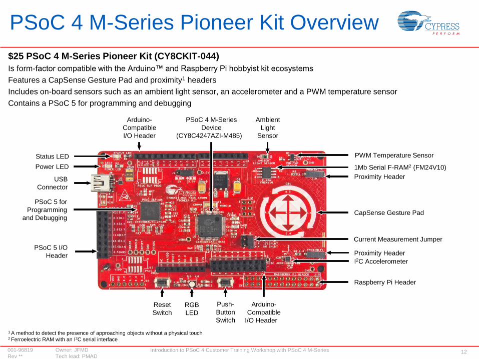
$25 PSoC 4 M-Series Pioneer Kit (CY8CKIT-044)
Is form-factor compatible with the Arduino™ and Raspberry Pi hobbyist kit ecosystems
Features a CapSense Gesture Pad and proximity1 headers
Includes on-board sensors such as an ambient light sensor, an accelerometer and a PWM temperature sensor
Contains a PSoC 5 for programming and debugging
1 A method to detect the presence of approaching objects without a physical touch2 Ferroelectric RAM with an I2C serial interface
PSoC 5 for
Programming
and Debugging
Arduino-
Compatible
I/O Header
Status LED
Power LED
Arduino-
Compatible
I/O Header
PSoC 5 I/O
Header
USB
Connector
RGB
LED
PSoC 4 M-Series
Device
(CY8C4247AZI-M485)
Ambient
Light
Sensor
1Mb Serial F-RAM2 (FM24V10)
Raspberry Pi Header
Reset
Switch
Push-
Button
Switch
PWM Temperature Sensor
Proximity Header
CapSense Gesture Pad
Proximity Header
Current Measurement Jumper
I2C Accelerometer
Introduction to PSoC 4 Customer Training Workshop with PSoC 4 M-Series 13001-96819 Owner: JFMD
Rev ** Tech lead: PMAD
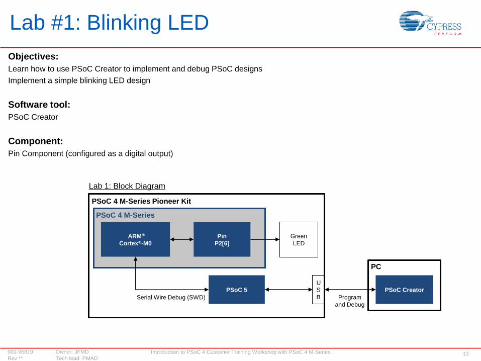
Objectives:
Learn how to use PSoC Creator to implement and debug PSoC designs
Implement a simple blinking LED design
Software tool:
PSoC Creator
Component:
Pin Component (configured as a digital output)
Lab #1: Blinking LED
Lab 1: Block Diagram
ARM®
Cortex®-M0
Pin
P2[6]
PSoC 4 M-Series
PSoC Creator
Green
LED
PSoC 4 M-Series Pioneer Kit
PSoC 5
Program
and Debug
Serial Wire Debug (SWD)
U
S
B
PC

Introduction to PSoC 4 Customer Training Workshop with PSoC 4 M-Series 14001-96819 Owner: JFMD
Rev ** Tech lead: PMAD
PSoC 4 ARCHITECTUREIntroduction to PSoC 4
Introduction to PSoC 4 Customer Training Workshop with PSoC 4 M-Series 15001-96819 Owner: JFMD
Rev ** Tech lead: PMAD
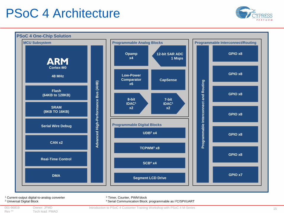
PSoC 4 Architecture
Flash
(64KB to 128KB)
12-bit SAR ADC
1 Msps
UDB2 x4
TCPWM3 x8
SCB4 x4
Segment LCD Drive
Pro
gra
mm
ab
le In
terc
on
ne
ct
an
d R
ou
tin
g
GPIO x8
Ad
va
nc
ed
Hig
h-P
erf
orm
an
ce
Bu
s (
AH
B)
PSoC 4 One-Chip Solution
Cortex-M0
48 MHz
Programmable Analog Blocks
Programmable Digital Blocks
SRAM
(8KB TO 16KB)
Serial Wire Debug
CAN x2
DMA
Real-Time Control
8-bit
IDAC1
x2
7-bit
IDAC1
x2
Opamp
x4
CapSense
Low-Power
Comparator
x6
GPIO x8
GPIO x8
GPIO x8
GPIO x8
GPIO x8
GPIO x7
MCU Subsystem Programmable Interconnect/Routing
1 Current-output digital-to-analog converter 3 Timer, Counter, PWM block 2 Universal Digital Block 4 Serial Communication Block; programmable as I2C/SPI/UART

Introduction to PSoC 4 Customer Training Workshop with PSoC 4 M-Series 16001-96819 Owner: JFMD
Rev ** Tech lead: PMAD
Programmable Digital Blocks Used for Coprocessors and Serial InterfacesPSoC 4 implements Coprocessors and serial interfaces without increasing cost, size or power with:
Universal Digital Blocks (UDBs) that can be configured as:
Timing-critical Coprocessors that simplify firmware and interrupt handling by replacing “bit-banging” firmware1
Custom serial communication interfaces for emerging standards that replace external glue logic ICs (e.g., Microwire2)
Serial Communication Blocks that can be configured as serial communication interfaces like I2C, UART, SPI or LIN
TCPWM Blocks that can be configured as timers, counters, PWMs or quadrature decoders
3 Programmable logic device (12C4 = 12 inputs with 4 combinatorial outputs)4 A technique used to combine elements of a UDB to form wider elements5 Product term: A logical conjunction of Boolean inputs6 A programmable element of a UDB that contains an arithmetic logic unit
1 A technique using firmware to directly control the state of I/Os2 A serial communication interface based on a subset of the SPI protocol
To program the UDB
Clock and
Reset
Control
Data
Path6
PLD3
12C4
(8 PTs5)
PLD3
12C4
(8 PTs5)
Status
and
Control
PLD3 Chaining4
Data
Path6
Chaining4
System Bus
1. Use digital logic Components in
the PSoC Creator schematic…
2. Or the graphical state
machine editor…
3. Or Verilog code in the
code editor…
Three Design Methods Used to Create Custom Digital Logic Using UDBs in PSoC Creator
Introduction to PSoC 4 Customer Training Workshop with PSoC 4 M-Series 17001-96819 Owner: JFMD
Rev ** Tech lead: PMAD
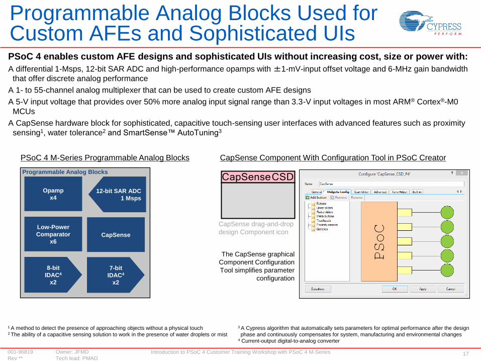
Programmable Analog Blocks Used for Custom AFEs and Sophisticated UIsPSoC 4 enables custom AFE designs and sophisticated UIs without increasing cost, size or power with:
A differential 1-Msps, 12-bit SAR ADC and high-performance opamps with ±1-mV-input offset voltage and 6-MHz gain bandwidth
that offer discrete analog performance
A 1- to 55-channel analog multiplexer that can be used to create custom AFE designs
A 5-V input voltage that provides over 50% more analog input signal range than 3.3-V input voltages in most ARM® Cortex®-M0
MCUs
A CapSense hardware block for sophisticated, capacitive touch-sensing user interfaces with advanced features such as proximity
sensing1, water tolerance2 and SmartSense™ AutoTuning3
PSoC 4 M-Series Programmable Analog Blocks CapSense Component With Configuration Tool in PSoC Creator
The CapSense graphical
Component Configuration
Tool simplifies parameter
configuration
Programmable Analog Blocks
1 A method to detect the presence of approaching objects without a physical touch 3 A Cypress algorithm that automatically sets parameters for optimal performance after the design2 The ability of a capacitive sensing solution to work in the presence of water droplets or mist phase and continuously compensates for system, manufacturing and environmental changes
4 Current-output digital-to-analog converter
12-bit SAR ADC
1 Msps
8-bit
IDAC4
x2
7-bit
IDAC4
x2
Opamp
x4
CapSense
Low-Power
Comparator
x6
CapSense drag-and-drop
design Component icon
Introduction to PSoC 4 Customer Training Workshop with PSoC 4 M-Series 18001-96819 Owner: JFMD
Rev ** Tech lead: PMAD
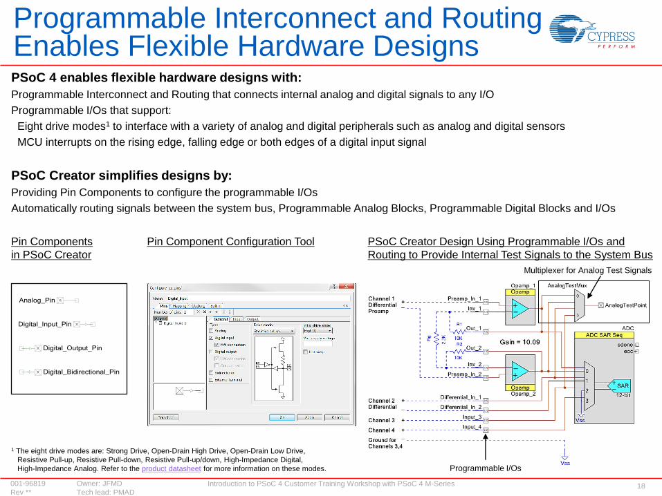
Programmable Interconnect and Routing Enables Flexible Hardware DesignsPSoC 4 enables flexible hardware designs with:
Programmable Interconnect and Routing that connects internal analog and digital signals to any I/O
Programmable I/Os that support:
Eight drive modes1 to interface with a variety of analog and digital peripherals such as analog and digital sensors
MCU interrupts on the rising edge, falling edge or both edges of a digital input signal
PSoC Creator simplifies designs by:
Providing Pin Components to configure the programmable I/Os
Automatically routing signals between the system bus, Programmable Analog Blocks, Programmable Digital Blocks and I/Os
Pin Component Configuration ToolPin Components
in PSoC Creator
PSoC Creator Design Using Programmable I/Os and
Routing to Provide Internal Test Signals to the System Bus
Programmable I/Os
Multiplexer for Analog Test Signals
1 The eight drive modes are: Strong Drive, Open-Drain High Drive, Open-Drain Low Drive,
Resistive Pull-up, Resistive Pull-down, Resistive Pull-up/down, High-Impedance Digital,
High-Impedance Analog. Refer to the product datasheet for more information on these modes.
Introduction to PSoC 4 Customer Training Workshop with PSoC 4 M-Series 19001-96819 Owner: JFMD
Rev ** Tech lead: PMAD
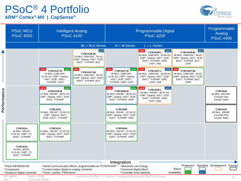
PSoC® 4 PortfolioARM® Cortex®-M0 | CapSense®
1 Flash KB/SRAM KB 4 Serial Communication Block; programmable as I2C/SPI/UART 7 Bluetooth Low Energy2 Comparator 5 Current-output digital-to-analog converter 8 Universal Digital Block 3 Analog-to-digital converter 6 Timer, counter, PWM block 9 Controller Area Network
Production Development
QQYYQQYYAvailability
Sampling Concept
Status
Integration
PSoC MCU
PSoC 4000
Intelligent Analog
PSoC 4100
Programmable Digital
PSoC 4200
Programmable
Analog
PSoC 4400
BL = BLE-Series M = M-Series L = L-Series
CY8C4013
16 MHz, 8K/2K1,
5-13 I/O, CMP2, I2C,
IDAC5, TCPWM6
CY8C4124
24 MHz, 16K/4K1, 22-36 I/O,
CMP2, Opamp, ADC3, SCB4,
IDAC5, TCPWM6
CY8C4244
48 MHz, 16K/4K1, 22-36 I/O,
CMP2, Opamp, ADC3, SCB4,
IDAC5, TCPWM6, UDB8
CY8C44x5
48 MHz, 32K/8K1
Concept Only
Contact Sales
CY8C44x6
48 MHz, 64K/16K1
Concept Only
Contact Sales
CY8C4127-M
24 MHz, 128K/16K1,
51-55 I/O, CMP2, Opamp,
ADC3, SCB4, IDAC5,
TCPWM6, CAN9
CY8C4247-BL
48 MHz, 128K/16K1, 36 I/O,
CMP2, Opamp, ADC3, SCB4,
IDAC5, TCPWM6, BLE7,
UDB8
CY8C4014
16 MHz, 16K/2K1,
5-20 I/O, CMP2, I2C,
IDAC5, TCPWM6
CY8C4125
24 MHz, 32K/4K1, 22-36 I/O,
CMP2, Opamp, ADC3,
SCB4, IDAC5, TCPWM6
CY8C4245
48 MHz, 32K/4K1, 22-36 I/O,
CMP2, Opamp, ADC3, SCB4,
IDAC5, TCPWM6, UDB8
CY8C4128-BL
24 MHz, 256K/32K1, 36 I/O,
CMP2, Opamp, ADC3, SCB4,
IDAC5, TCPWM6, BLE7
CY8C4248-BL
48 MHz, 256K/32K1, 36 I/O,
CMP2, Opamp, ADC3, SCB4,
IDAC5, TCPWM6, BLE7,
UDB8
Pe
rfo
rma
nc
e
CY8C4246-M
48 MHz, 64K/8K1, 38-55 I/O,
CMP2, Opamp, ADC3, SCB4,
IDAC5, TCPWM6, UDB8
CY8C4126-M
24 MHz, 64K/8K1, 38-51 I/O,
CMP2, Opamp, ADC3, SCB4,
IDAC5, TCPWM6
CY8C4247-L
48 MHz, 128K/16K1, 38-98 I/O,
CMP2, Opamp, ADC3, SCB4,
IDAC5, TCPWM6, UDB8,
CAN9, USB
CY8C4248-L
48 MHz, 256K/32K1, 53-98 I/O,
CMP2, Opamp, ADC3, SCB4,
IDAC5, TCPWM6, UDB8,
CAN9, USB
CY8C4127-BL
24 MHz, 128K/16K1, 36 I/O,
CMP2, Opamp, ADC3, SCB4,
IDAC5, TCPWM6, BLE7
CY8C4247-M
48 MHz, 128K/16K1,
51-55 I/O, CMP2, Opamp,
ADC3, SCB4, IDAC5,
TCPWM6, UDB8, CAN9
NEW
NEW NEW NEW
NEW
NEW
NEW
NEWQ215
Q215
Q215
Q215
Q315
Q315Q215 Q215
CY8C4246-L
48 MHz, 64K/8K1, 38-57 I/O,
CMP2, Opamp, ADC3, SCB4,
IDAC5, TCPWM6, UDB8,
CAN9, USB
NEW Q315

Introduction to PSoC 4 Customer Training Workshop with PSoC 4 M-Series 20001-96819 Owner: JFMD
Rev ** Tech lead: PMAD
DEMO #2: MICRIUM µC/PROBEIntroduction to PSoC 4
Introduction to PSoC 4 Customer Training Workshop with PSoC 4 M-Series 21001-96819 Owner: JFMD
Rev ** Tech lead: PMAD
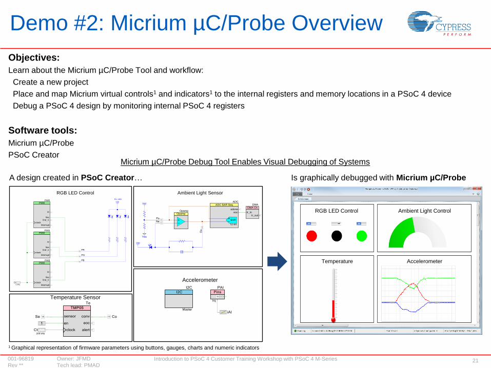
Objectives:
Learn about the Micrium µC/Probe Tool and workflow:
Create a new project
Place and map Micrium virtual controls1 and indicators1 to the internal registers and memory locations in a PSoC 4 device
Debug a PSoC 4 design by monitoring internal PSoC 4 registers
Software tools:
Micrium µC/Probe
PSoC Creator
Demo #2: Micrium µC/Probe Overview
Micrium µC/Probe Debug Tool Enables Visual Debugging of Systems
1 Graphical representation of firmware parameters using buttons, gauges, charts and numeric indicators
RGB LED Control Ambient Light Control
AccelerometerTemperature
Is graphically debugged with Micrium µC/ProbeA design created in PSoC Creator…
RGB LED Control Ambient Light Sensor
Accelerometer
Temperature Sensor
Introduction to PSoC 4 Customer Training Workshop with PSoC 4 M-Series 22001-96819 Owner: JFMD
Rev ** Tech lead: PMAD
SESSION BREAKIntroduction to PSoC 4

Introduction to PSoC 4 Customer Training Workshop with PSoC 4 M-Series 23001-96819 Owner: JFMD
Rev ** Tech lead: PMAD
LAB #2: DIGITAL SYSTEM DESIGNIntroduction to PSoC 4
Introduction to PSoC 4 Customer Training Workshop with PSoC 4 M-Series 24001-96819 Owner: JFMD
Rev ** Tech lead: PMAD
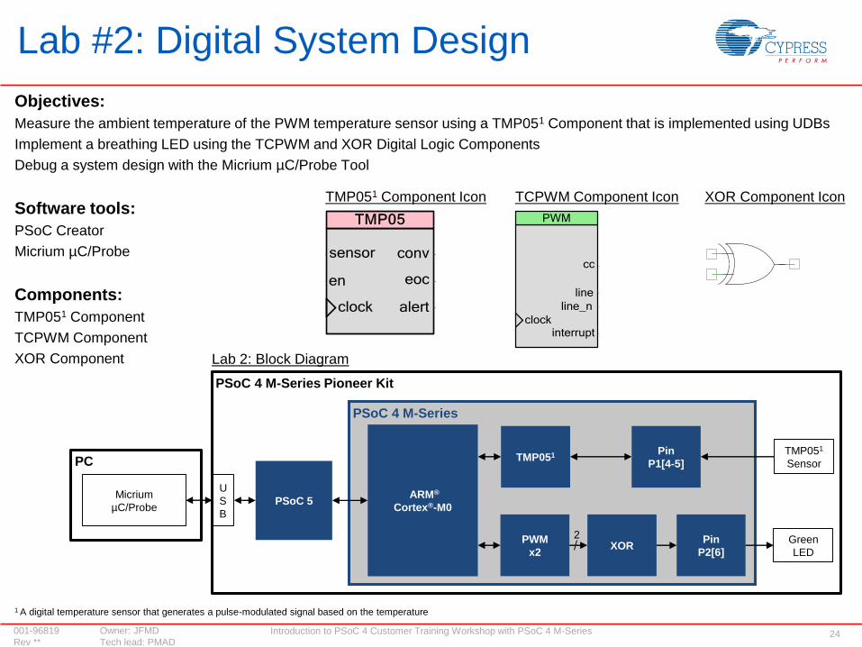
Objectives:
Measure the ambient temperature of the PWM temperature sensor using a TMP051 Component that is implemented using UDBs
Implement a breathing LED using the TCPWM and XOR Digital Logic Components
Debug a system design with the Micrium µC/Probe Tool
Software tools:
PSoC Creator
Micrium µC/Probe
Components:
TMP051 Component
TCPWM Component
XOR Component
Lab #2: Digital System Design
Lab 2: Block Diagram
ARM®
Cortex®-M0
PSoC 4 M-Series
Pin
P1[4-5]TMP051 TMP051
Sensor
PSoC 4 M-Series Pioneer Kit
PSoC 5Micrium
µC/Probe
U
S
B
Pin
P2[6]
PWM
x2
Green
LEDXOR
XOR Component IconTCPWM Component IconTMP051 Component Icon
2
1 A digital temperature sensor that generates a pulse-modulated signal based on the temperature
PC
Introduction to PSoC 4 Customer Training Workshop with PSoC 4 M-Series 25001-96819 Owner: JFMD
Rev ** Tech lead: PMAD
LAB #3: CapSense TOUCH-SENSING DESIGNIntroduction to PSoC 4

Introduction to PSoC 4 Customer Training Workshop with PSoC 4 M-Series 26001-96819 Owner: JFMD
Rev ** Tech lead: PMAD
CapSense replaces mechanical buttons
A capacitive sensor is used to measure the change in capacitance between a pin and ground
CapSense algorithms and analog circuitry convert the measured capacitance to a raw count
A finger touch increases the capacitance of the system, which in turn increases the raw count
An increase in the raw count above a user-defined threshold registers a touch
Refer to the Getting Started With CapSense Guide for details on CapSense algorithms
CapSense Touch Sensing
CX = 2CP
PCB
Overlay
CP CP
Copper
Ground
Copper
Ground
Capacitive
Sensor
CX = 2CP + CF
PCB
Overlay
CP CP
Copper
Ground
Copper
Ground
CF
Capacitive
Sensor
Capacitive Sensor
Without a Finger Touch
Capacitive Sensor
With a Finger Touch
CF = Capacitance added by a finger touch
CF is dependent on the overlay material, overlay
thickness and the dimensions of the finger
(typical = 9mm) and sensor capacitances
CX = Total Capacitance on the
capacitive sensor node
CP = Parasitic capacitance
Raw Count Variation on Finger Touch
3460
3480
3500
3520
3540
3560
3580
3600
3620
3640
3660
0 200 400 600 800 1000 1200 1400 1600
Sig
nal
Noise
No Touch Touch
Baseline
Raw
Cou
nt
Time (ms)
Threshold
CapSense algorithms use analog circuits to
convert the capacitance to raw count, which
is compared to the user-defined threshold
to record a touch
800400 1,2000 1,600
1,5
50
1,5
00
1,6
00
1,6
50
1,7
00
No Touch
Introduction to PSoC 4 Customer Training Workshop with PSoC 4 M-Series 27001-96819 Owner: JFMD
Rev ** Tech lead: PMAD
SmartSense Auto-tuning
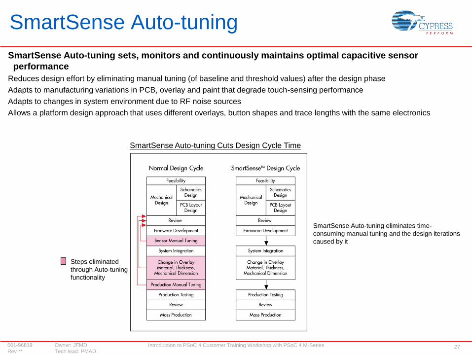
SmartSense Auto-tuning sets, monitors and continuously maintains optimal capacitive sensor
performance
Reduces design effort by eliminating manual tuning (of baseline and threshold values) after the design phase
Adapts to manufacturing variations in PCB, overlay and paint that degrade touch-sensing performance
Adapts to changes in system environment due to RF noise sources
Allows a platform design approach that uses different overlays, button shapes and trace lengths with the same electronics
Steps eliminated
through Auto-tuning
functionality
SmartSense Auto-tuning eliminates time-
consuming manual tuning and the design iterations
caused by it
SmartSense Auto-tuning Cuts Design Cycle Time

Introduction to PSoC 4 Customer Training Workshop with PSoC 4 M-Series 28001-96819 Owner: JFMD
Rev ** Tech lead: PMAD
CapSense Touch Sensing Enables Sophisticated User InterfacesPSoC 4 tracks finger movements and touch-based gestures in two dimensions
Swipe gestures track up, down, left and right finger movements
Circular gestures track clockwise and counter-clockwise finger movements
Refer to the PSoC 4 M-Series Pioneer Kit Guide for details on touch-based gestures
CapSense maintains touch accuracy even in wet conditions
Refer to the Getting Started With CapSense Guide for details on liquid tolerance
The PSoC 4 M-Series Pioneer Kit provides a platform to implement touch-based gestures rapidly
Circular Gesture: Clockwise/
Counter-Clockwise
Swipe Gesture: Up/Down Swipe Gesture: Left/Right
CapSense Gestures on the PSoC 4 M-Series Pioneer Kit (CY8CKIT-044)
CapSense Gesture Pad
Washing Machine With a Liquid-Tolerant UI
Touch-sensing user
interfaces are designed
into end products that are
exposed to liquids

Introduction to PSoC 4 Customer Training Workshop with PSoC 4 M-Series 29001-96819 Owner: JFMD
Rev ** Tech lead: PMAD
Objectives:
Adjust the RGB LED color and intensity using three TCPWM Components
Implement CapSense touch-based gestures using the CapSense Gesture Pad
Software tool:
PSoC Creator
Components:
TCPWM Components
CapSense CSD Component
Lab #3: CapSense Touch-Sensing Design
Lab 3: Block Diagram
CapSense CSD Component Icon
ARM®
Cortex®-M0
CapSense
Gesture PadCapSense
P3[4-5],
P4[4-6]
TCPWM
x3RGB LED
P0[6],
P2[6],
P6[5]
PSoC 4 M-Series Pioneer Kit
PSoC 4 M-Series
TCPWM Component Icon

Introduction to PSoC 4 Customer Training Workshop with PSoC 4 M-Series 30001-96819 Owner: JFMD
Rev ** Tech lead: PMAD
LAB #4: SENSOR-BASED SYSTEM DESIGNIntroduction to PSoC 4
Introduction to PSoC 4 Customer Training Workshop with PSoC 4 M-Series 31001-96819 Owner: JFMD
Rev ** Tech lead: PMAD
Sensor-Based System Design
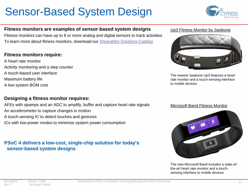
Fitness monitors are examples of sensor-based system designs
Fitness monitors can have up to 8 or more analog and digital sensors to track activities
To learn more about fitness monitors, download our Wearables Solutions Catalog
Fitness monitors require:
A heart rate monitor
Activity monitoring and a step counter
A touch-based user interface
Maximum battery life
A low system BOM cost
Designing a fitness monitor requires:
AFEs with opamps and an ADC to amplify, buffer and capture heart rate signals
An accelerometer to capture changes in motion
A touch-sensing IC to detect touches and gestures
ICs with low-power modes to minimize system power consumption
PSoC 4 delivers a low-cost, single-chip solution for today’s
sensor-based system designs
Microsoft Band Fitness Monitor
Up3 Fitness Monitor by Jawbone
The newest Jawbone Up3 features a heart
rate monitor and a touch-sensing interface
to mobile devices
The new Microsoft Band includes a state-of-
the-art heart rate monitor and a touch-
sensing interface to mobile devices
Introduction to PSoC 4 Customer Training Workshop with PSoC 4 M-Series 32001-96819 Owner: JFMD
Rev ** Tech lead: PMAD
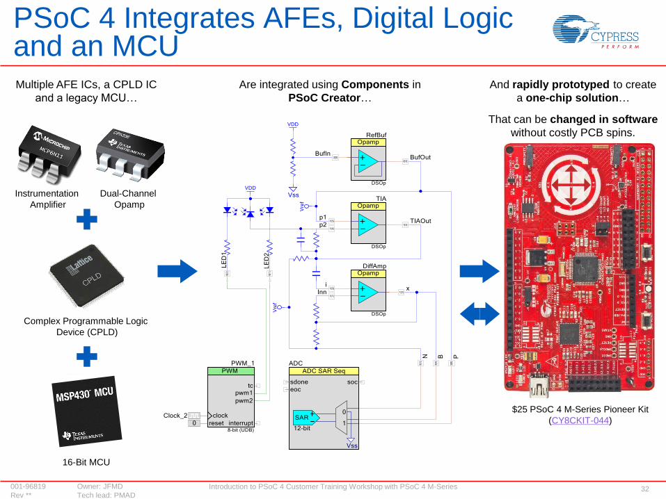
PSoC 4 Integrates AFEs, Digital Logic and an MCUMultiple AFE ICs, a CPLD IC
and a legacy MCU…
Are integrated using Components in
PSoC Creator…
And rapidly prototyped to create
a one-chip solution…
Dual-Channel
Opamp
Instrumentation
Amplifier
Complex Programmable Logic
Device (CPLD)
16-Bit MCU
That can be changed in software
without costly PCB spins.
$25 PSoC 4 M-Series Pioneer Kit
(CY8CKIT-044)
Introduction to PSoC 4 Customer Training Workshop with PSoC 4 M-Series 33001-96819 Owner: JFMD
Rev ** Tech lead: PMAD
PSoC 4 Delivers Five Flexible, Easy-to-Use Low-Power Modes
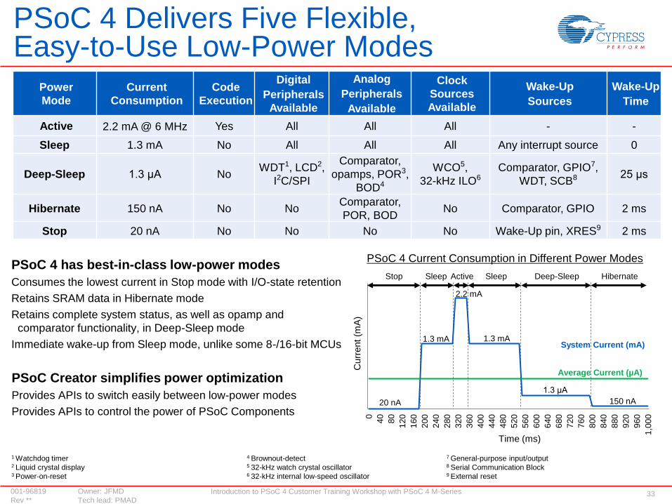
PSoC 4 has best-in-class low-power modes
Consumes the lowest current in Stop mode with I/O-state retention
Retains SRAM data in Hibernate mode
Retains complete system status, as well as opamp and
comparator functionality, in Deep-Sleep mode
Immediate wake-up from Sleep mode, unlike some 8-/16-bit MCUs
PSoC Creator simplifies power optimization
Provides APIs to switch easily between low-power modes
Provides APIs to control the power of PSoC Components
Power
Mode
Current
Consumption
Code
Execution
Digital
Peripherals
Available
Analog
Peripherals
Available
Clock
Sources
Available
Wake-Up
Sources
Wake-Up
Time
Active 2.2 mA @ 6 MHz Yes All All All - -
Sleep 1.3 mA No All All All Any interrupt source 0
Deep-Sleep 1.3 μA NoWDT1, LCD2,
I2C/SPI
Comparator,
opamps, POR3,
BOD4
WCO5,
32-kHz ILO6Comparator, GPIO7,
WDT, SCB8 25 μs
Hibernate 150 nA No NoComparator,
POR, BODNo Comparator, GPIO 2 ms
Stop 20 nA No No No No Wake-Up pin, XRES9 2 ms
1 Watchdog timer 4 Brownout-detect 7 General-purpose input/output 2 Liquid crystal display 5 32-kHz watch crystal oscillator 8 Serial Communication Block 3 Power-on-reset 6 32-kHz internal low-speed oscillator 9 External reset
PSoC 4 Current Consumption in Different Power Modes
System Current (mA)
Average Current (µA)0
40
80
120
160
200
240
280
320
360
400
440
480
520
560
600
640
680
720
760
800
840
880
920
960
1,0
00
Curr
ent (m
A)
Stop Sleep Active Sleep Deep-Sleep Hibernate
2.2 mA
1.3 mA
1.3 μA
150 nA
1.3 mA
20 nA
Time (ms)

Introduction to PSoC 4 Customer Training Workshop with PSoC 4 M-Series 34001-96819 Owner: JFMD
Rev ** Tech lead: PMAD
Objectives
Measure ambient light intensity using an ambient light sensor
Control the LED intensity based on the ambient light intensity
Software tools
PSoC Creator
Micrium µC/Probe
Components
SAR1 ADC Component
Opamp Component
Lab #4: Sensor-Based System Design
ARM®
Cortex®-M0
PWMPin
P2[6]
Ambient
Light Sensor
SAR ADC Component
Lab 4: Block Diagram
Green
LED
PSoC 4 M-Series Pioneer Kit
PSoC 4 M-Series
1 Trans-impedance amplifier using PSoC 4 Programmable Analog Blocks
TIA1Pin
P5[1]
AccelerometerPin
P4[0-1]I2C XOR
Pin
P1[4-5]TMP05
TMP05
Sensor
2
Opamp Component
SAR
ADC
Introduction to PSoC 4 Customer Training Workshop with PSoC 4 M-Series 35001-96819 Owner: JFMD
Rev ** Tech lead: PMAD
WRAP-UPIntroduction to PSoC 4
Introduction to PSoC 4 Customer Training Workshop with PSoC 4 M-Series 36001-96819 Owner: JFMD
Rev ** Tech lead: PMAD
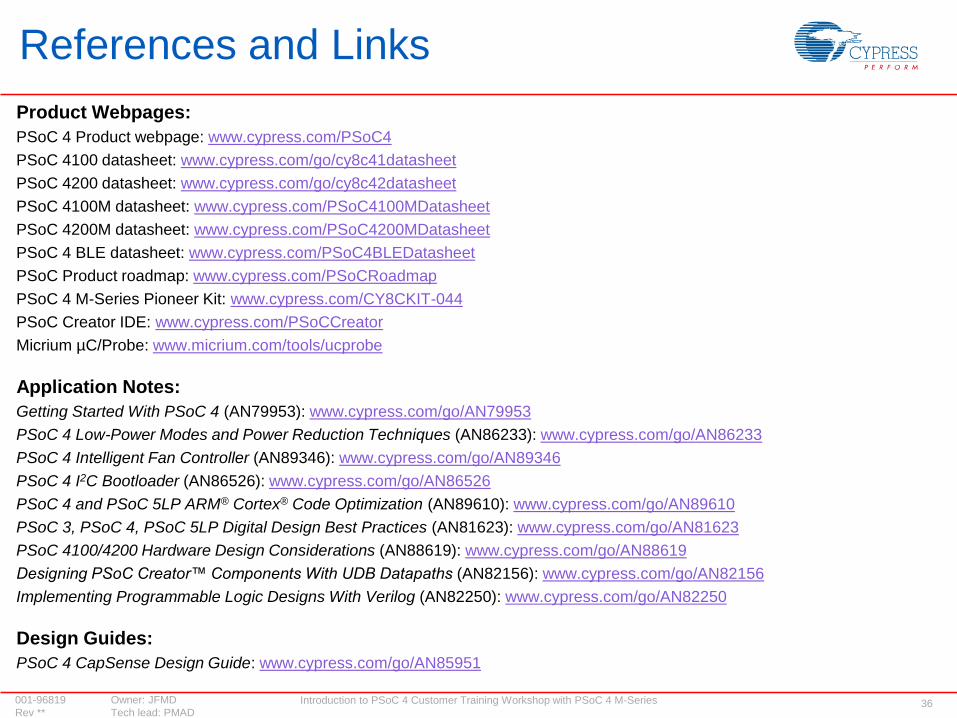
References and Links
Product Webpages:
PSoC 4 Product webpage: www.cypress.com/PSoC4
PSoC 4100 datasheet: www.cypress.com/go/cy8c41datasheet
PSoC 4200 datasheet: www.cypress.com/go/cy8c42datasheet
PSoC 4100M datasheet: www.cypress.com/PSoC4100MDatasheet
PSoC 4200M datasheet: www.cypress.com/PSoC4200MDatasheet
PSoC 4 BLE datasheet: www.cypress.com/PSoC4BLEDatasheet
PSoC Product roadmap: www.cypress.com/PSoCRoadmap
PSoC 4 M-Series Pioneer Kit: www.cypress.com/CY8CKIT-044
PSoC Creator IDE: www.cypress.com/PSoCCreator
Micrium µC/Probe: www.micrium.com/tools/ucprobe
Application Notes:
Getting Started With PSoC 4 (AN79953): www.cypress.com/go/AN79953
PSoC 4 Low-Power Modes and Power Reduction Techniques (AN86233): www.cypress.com/go/AN86233
PSoC 4 Intelligent Fan Controller (AN89346): www.cypress.com/go/AN89346
PSoC 4 I2C Bootloader (AN86526): www.cypress.com/go/AN86526
PSoC 4 and PSoC 5LP ARM® Cortex® Code Optimization (AN89610): www.cypress.com/go/AN89610
PSoC 3, PSoC 4, PSoC 5LP Digital Design Best Practices (AN81623): www.cypress.com/go/AN81623
PSoC 4100/4200 Hardware Design Considerations (AN88619): www.cypress.com/go/AN88619
Designing PSoC Creator™ Components With UDB Datapaths (AN82156): www.cypress.com/go/AN82156
Implementing Programmable Logic Designs With Verilog (AN82250): www.cypress.com/go/AN82250
Design Guides:
PSoC 4 CapSense Design Guide: www.cypress.com/go/AN85951

Introduction to PSoC 4 Customer Training Workshop with PSoC 4 M-Series 37001-96819 Owner: JFMD
Rev ** Tech lead: PMAD
General Online Resources
Cypress Resources
PSoC Product webpage: www.cypress.com/PSoC
Cypress Roadmap: www.cypress.com/Roadmap
Kits: www.cypress.com/kits
Support: www.cypress.com/support
Workshops: www.cypress.com/workshops
Cypress Online Store: www.cypress.com/store
Developer Community & Forums: www.cypress.com/forums
App Notes: www.cypress.com/AppNotes
Cypress PSoC 4 M-Series Solutions: www.cypress.com/PSoC4
Cypress’s PSoC 4 M-Series webpage is your one-stop-shop for everything,
including product datasheets, development kits, app notes, software downloads,
example projects and demo videos

Introduction to PSoC 4 Customer Training Workshop with PSoC 4 M-Series 38001-96819 Owner: JFMD
Rev ** Tech lead: PMAD
Workshop Objectives Recap
You should now:
Understand the architecture of the PSoC 4 Programmable System-on-Chip
Know how to use the PSoC Creator IDE and the PSoC 4 M-Series Pioneer Kit to design with PSoC 4, to implement:
Digital designs with PSoC 4
CapSense touch-sensing user interface designs with PSoC 4
One-chip, sensor-based system designs with PSoC 4
Please help us improve this workshop by completing our feedback form
Introduction to PSoC 4 Customer Training Workshop with PSoC 4 M-Series 39001-96819 Owner: JFMD
Rev ** Tech lead: PMAD
APPENDIXIntroduction to PSoC 4
Introduction to PSoC 4 Customer Training Workshop with PSoC 4 M-Series 40001-96819 Owner: JFMD
Rev ** Tech lead: PMAD
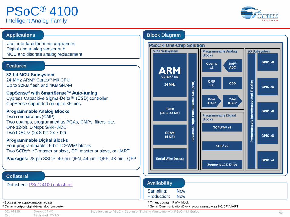
PSoC® 4100Intelligent Analog Family
User interface for home appliances
Digital and analog sensor hub
MCU and discrete analog replacement
Applications
32-bit MCU Subsystem
24-MHz ARM® Cortex®-M0 CPU
Up to 32KB flash and 4KB SRAM
CapSense® with SmartSense™ Auto-tuning
Cypress Capacitive Sigma-Delta™ (CSD) controller
CapSense supported on up to 36 pins
Programmable Analog Blocks
Two comparators (CMP)
Two opamps, programmed as PGAs, CMPs, filters, etc.
One 12-bit, 1-Msps SAR1 ADC
Two IDACs2 (2x 8-bit, 2x 7-bit)
Programmable Digital Blocks
Four programmable 16-bit TCPWM3 blocks
Two SCBs4: I2C master or slave, SPI master or slave, or UART
Packages: 28-pin SSOP, 40-pin QFN, 44-pin TQFP, 48-pin LQFP
Features
Datasheet: PSoC 4100 datasheet
Collateral
Block Diagram
Sampling: Now
Production: Now
Availability
Flash
(16 to 32 KB)
SRAM
(4 KB)
Serial Wire Debug
Segment LCD Drive
Pro
gra
mm
ab
le In
terc
on
ne
ct
an
d R
ou
tin
g
GPIO x8
PSoC 4 One-Chip Solution
Cortex®-M0
24 MHz
Programmable Digital
Blocks
SCB4 x2
TCPWM3 x4
SAR1
ADC
Programmable Analog
Blocks
Opamp
x2
CMP
x2
I/O SubsystemMCU Subsystem
GPIO x8
GPIO x8
GPIO x4
Ad
van
ced
Hig
h-P
erf
orm
an
ce B
us
(A
HB
)
CSDGPIO x8
8-bit
IDAC2
7-bit
IDAC2
1 Successive approximation register 3 Timer, counter, PWM block 2 Current-output digital-to-analog converter 4 Serial Communication Block, programmable as I2C/SPI/UART

Introduction to PSoC 4 Customer Training Workshop with PSoC 4 M-Series 41001-96819 Owner: JFMD
Rev ** Tech lead: PMAD
PSoC® 4200Programmable Digital Family
User interface for home appliances
Digital and analog sensor hub
MCU and discrete analog replacement
Applications
32-bit MCU Subsystem
48-MHz ARM® Cortex®-M0 CPU
Up to 32KB flash and 4KB SRAM
CapSense® with SmartSense™ Auto-tuning
Cypress Capacitive Sigma-Delta™ (CSD) controller
CapSense supported on up to 36 pins
Programmable Analog Blocks
Two comparators (CMP)
Two opamps, programmed as PGAs, CMPs, filters, etc.
One 12-bit, 1-Msps SAR1 ADC
Two IDACs2 (2x 8-bit, 2x 7-bit)
Programmable Digital Blocks
Four Universal Digital Blocks (UDBs3): custom digital peripherals
Four programmable 16-bit TCPWM4 blocks
Two SCBs5: I2C master or slave, SPI master or slave, or UART
Packages: 28-pin SSOP, 40-pin QFN, 44-pin TQFP, 48-pin LQFP
Features
Datasheet: PSoC 4200 datasheet
Collateral
Block Diagram
Sampling: Now
Production: Now
Availability
Flash
(16 to 32 KB)
SRAM
(4 KB)
Serial Wire Debug
Segment LCD Drive
Pro
gra
mm
ab
le In
terc
on
ne
ct
an
d R
ou
tin
g
GPIO x8
PSoC 4 One-Chip Solution
Cortex®-M0
48 MHz
Programmable Digital
Blocks
SCB5 x2
TCPWM4 x4
SAR1
ADC
Programmable Analog
Blocks
Opamp
x2
CMP
x2
I/O SubsystemMCU Subsystem
GPIO x8
GPIO x8
GPIO x4
Ad
van
ced
Hig
h-P
erf
orm
an
ce B
us
(A
HB
)
CSDGPIO x8
8-bit
IDAC2
7-bit
IDAC2
1 Successive approximation register 3 Universal Digital Block 5 Serial Communication Block, programmable as I2C/SPI/UART2 Current-output digital-to-analog converter 4 Timer, counter, PWM block
UDB3 x4

Introduction to PSoC 4 Customer Training Workshop with PSoC 4 M-Series 42001-96819 Owner: JFMD
Rev ** Tech lead: PMAD
Sports and fitness monitors, wearable electronics, medical devices,
home automation solutions, game controllers, sensor-based
low-power systems for the Internet of Things (IoT)
32-bit MCU subsystem
24-MHz ARM® Cortex®-M0 CPU
Up to 256KB flash and 32KB SRAM
Programmable Analog Blocks
Four opamps, configurable as PGAs, comparators, filters, etc.
One 12-bit, 1-Msps SAR1 ADC
CapSense® with SmartSense™ Auto-tuning
One Cypress Capacitive Sigma-Delta™ (CSD) controller with
touchpad capability
Programmable Digital Blocks
Four configurable TCPWM2 blocks: 16-bit timer, counter or PWM
Two configurable serial communication blocks (SCBs)3:
I2C master or slave, SPI master or slave, or UART
Packages
56-pin QFN, 68-pin CSP
Bluetooth Smart connectivity with Bluetooth 4.1
2.4-GHz BLE radio with integrated Balun
Sampling: Now
Production: Now
Datasheet: PSoC 4100 BLE datasheet
Applications
Features
Collateral
Block Diagram
Availability
Flash
(128KB to 256KB)
SRAM
(16KB to 32KB)
Serial Wire Debug
Pro
gra
mm
ab
le In
terc
on
ne
ct
an
d R
ou
tin
g
GPIO x8
PSoC 4 BLE One-Chip Solution
Cortex®-M0
24 MHz
Programmable Digital
Blocks
SCB3 x2
TCPWM2 x4
SAR1
ADC
Programmable Analog
Blocks
Opamp
x4
CMP
x2
I/O SubsystemMCU Subsystem
Segment LCD Drive
GPIO x8
GPIO x8
GPIO x8
GPIO x4
Ad
van
ced
Hig
h-P
erf
orm
an
ce B
us
(A
HB
)
CSD
BLE System
PSoC® 4100 BLE-SeriesIntelligent Analog Family with Bluetooth Low Energy
1 Successive approximation register2 Timer, counter, PWM block 3 Serial Communication Block, programmable as I2C/SPI/UART

Introduction to PSoC 4 Customer Training Workshop with PSoC 4 M-Series 43001-96819 Owner: JFMD
Rev ** Tech lead: PMAD
Sports and fitness monitors, wearable electronics, medical devices,
home automation solutions, game controllers, sensor-based
low-power systems for the Internet of Things (IoT)
32-bit MCU subsystem
48-MHz ARM® Cortex®-M0 CPU
Up to 256KB flash and 32KB SRAM
Programmable Analog Blocks
Four opamps, configurable as PGAs, comparators, filters, etc.
One 12-bit, 1-Msps SAR1 ADC
CapSense® with SmartSense™ Auto-tuning
One Cypress Capacitive Sigma-Delta™ (CSD) controller with
touchpad capability
Programmable Digital Blocks
Four Universal Digital Blocks (UDBs2): custom digital peripherals
Four configurable TCPWM3 blocks: 16-bit timer, counter or PWM
Two configurable serial communication blocks (SCBs4):
I2C master or slave, SPI master or slave, or UART
Packages
56-pin QFN, 68-pin CSP
Bluetooth Smart connectivity with Bluetooth 4.1
2.4-GHz BLE radio with integrated Balun
Sampling: Now
Production: Now
Datasheet: PSoC 4200 BLE datasheet
Applications
Features
Collateral
Block Diagram
Availability
Flash
(128KB to 256KB)
SRAM
(16KB to 32KB)
Serial Wire Debug
Pro
gra
mm
ab
le In
terc
on
ne
ct
an
d R
ou
tin
g
GPIO x8
PSoC 4 BLE One-Chip Solution
Cortex®-M0
48 MHz
Programmable Digital
Blocks
SCB4 x2
TCPWM3 x4
UDB2 x4
SAR1
ADC
Programmable Analog
Blocks
Opamp
x4
CMP
x2
I/O SubsystemMCU Subsystem
Segment LCD Drive
GPIO x8
GPIO x8
GPIO x8
GPIO x4
Ad
van
ced
Hig
h-P
erf
orm
an
ce B
us
(A
HB
)
CSD
BLE System
PSoC® 4200 BLE-SeriesProgrammable Digital Family with Bluetooth Low Energy
1 Successive approximation register 3 Timer, counter, PWM block 2 Universal Digital Block 4 Serial Communication Block, programmable as I2C/SPI/UART

Introduction to PSoC 4 Customer Training Workshop with PSoC 4 M-Series 44001-96819 Owner: JFMD
Rev ** Tech lead: PMAD
User interface and host processor for home appliances
Digital and analog sensor hub
MCU and discrete analog replacement
Applications
32-bit MCU Subsystem
24-MHz ARM® Cortex®-M0 CPU with a DMA controller and RTC
Up to 128KB flash and 16KB SRAM
Up to 55 GPIOs supporting analog, digital and CapSense interfaces
CapSense® With SmartSense™ Auto-tuning
Cypress Capacitive Sigma-Delta™ (CSD) controller
Programmable Analog Blocks
Six comparators (CMP)
Four opamps, programmable as PGAs, CMPs, filters, etc.
One 12-bit, 1-Msps SAR1 ADC
Four IDACs2 (2x 8-bit, 2x 7-bit)
Programmable Digital Blocks
Eight programmable 16-bit TCPWM3 blocks
Four SCBs4: I2C master or slave, SPI master or slave, or UART
Two Controller Area Network (CAN) Controllers
Packages: 48-pin LQFP, 64-pin TQFP (0.8-mm pitch),
64-pin TQFP (0.5-mm pitch), 68-pin QFN
Features
Datasheet: PSoC 4100M datasheet
Collateral
Block Diagram
Sampling: Now
Production: Q2 2015
Availability
Flash
(64KB to 128KB)
SRAM
(8KB to 16KB)
Serial Wire Debug
Segment LCD Drive
Pro
gra
mm
ab
le In
terc
on
ne
ct
an
d R
ou
tin
g
GPIO x8
PSoC® 4 One-Chip Solution
Cortex®-M0
24 MHz
Programmable Digital
Blocks
SCB4 x4
TCPWM3 x8
SAR1
ADC
Programmable Analog
Blocks
Opamp
x4
CMP
x6
I/O SubsystemMCU Subsystem
CAN x2
GPIO x8
GPIO x8
GPIO x8
GPIO x8
GPIO x7
Ad
van
ced
Hig
h-P
erf
orm
an
ce B
us
(A
HB
)
CSD
GPIO x8
RTC
DMA
8-bit
IDAC2
x2
7-bit
IDAC2
x2
1 Successive approximation register 3 Timer, counter, PWM block 2 Current-output digital-to-analog converter 4 Serial Communication Block, programmable as I2C/SPI/UART
PSoC® 4100 M-SeriesIntelligent Analog Family

Introduction to PSoC 4 Customer Training Workshop with PSoC 4 M-Series 45001-96819 Owner: JFMD
Rev ** Tech lead: PMAD
User interface and host processor for home appliances
Digital and analog sensor hub
LED control and communication for lighting systems
Applications
32-bit MCU Subsystem
48-MHz ARM® Cortex®-M0 CPU with a DMA controller and RTC
Up to 128KB flash and 16KB SRAM
Up to 55 GPIOs supporting analog, digital and CapSense interfaces
CapSense® With SmartSense™ Auto-tuning
Cypress Capacitive Sigma-Delta™ (CSD) controller
Programmable Analog Blocks
Six comparators (CMP)
Four opamps, programmable as PGAs, CMPs, filters, etc.
One 12-bit, 1-Msps SAR1 ADC
Four IDACs2 (2x 8-bit, 2x 7-bit)
Programmable Digital Blocks
Four Universal Digital Blocks (UDBs3): custom digital peripherals
Eight programmable 16-bit TCPWM4 blocks
Four SCBs5: I2C master or slave, SPI master or slave, or UART
Two Controller Area Network (CAN) Controllers
Packages: 48-pin LQFP, 64-pin TQFP (0.8-mm pitch),
64-pin TQFP (0.5-mm pitch), 68-pin QFN
Features
Datasheet: PSoC 4200M datasheet
Collateral
Block Diagram
Sampling: Now
Production: Q2 2015
Availability
Flash
(64KB to 128KB)
SRAM
(8KB to 16KB)
Serial Wire Debug
Segment LCD Drive
Pro
gra
mm
ab
le In
terc
on
ne
ct
an
d R
ou
tin
g
GPIO x8
PSoC® 4 One-Chip Solution
Cortex®-M0
48 MHz
Programmable Digital
Blocks
SCB5 x4
TCPWM4 x8
UDB3 x4
SAR1
ADC
Programmable Analog
Blocks
Opamp
x4
CMP
x6
I/O SubsystemMCU Subsystem
CAN x2
GPIO x8
GPIO x8
GPIO x8
GPIO x8
GPIO x7
Ad
van
ced
Hig
h-P
erf
orm
an
ce B
us
(A
HB
)
CSD
GPIO x8
RTC
DMA
1 Successive approximation register 3 Universal Digital Block 5 Serial Communication Block, programmable as I2C/SPI/UART2 Current-output digital-to-analog converter 4 Timer, counter, PWM block
8-bit
IDAC2
x2
7-bit
IDAC2
x2
PSoC® 4200 M-SeriesProgrammable Digital Family