curved micromachined surfaces in polymeric material for ... · ojämnheter i ytan de växer på ser...
TRANSCRIPT
UPTEC X 01 026 ISSN 1401-2138MAY 2001
LOVISA FORSSELL
Curvedmicromachinedsurfaces in polymericmaterial for cellculturing
Master’s degree project
Molecular Biotechnology ProgrammeUppsala University School of Engineering
UPTEC X 01 026 Date of issue 2001-05Author
Lovisa Forssell
Title (English)Curved micromachined surfaces in polymeric material for cell
culturing
Title (Swedish)
Abstract
Earlier work has shown that human cells react to very small structures with sharp edges. Inthis Degree project, a method for production of well-defined curved micromachined structuresin polycaprolactone (PCL) was developed. Human fibroblasts were cultured on thesestructures and fluorescence stained for actin. Cells were found to align to and stretch along thegrooves.
Keywords
Micromachining, quartz, polycaprolactone, cytoskeleton, fibroblasts, fluorescence
SupervisorsFredrik Nikolajeff
Materials Science Division, Uppsala University
ExaminerKarin Caldwell
Center for Surface Biotechnology, Uppsala University
Project name SponsorsLanguage
EnglishSecurity
ISSN 1401-2138Classification
Supplementary bibliographical information Pages18
Biology Education Centre Biomedical Center Husargatan 3 UppsalaBox 592 S-75124 Uppsala Tel +46 (0)18 4710000 Fax +46 (0)18 555217

SUMMARY IN SWEDISH
Sammanfattning
Om man doppar en bit kvarts (glas) i en starkt frätande vätska kommer kvartsen sakta lösasupp. Med ett skyddande mönster av krom på kvartsbitens yta kommer dock bara de områdensom inte är skyddade att utsättas för frätning. På så sätt kan man skapa ett mönster av groparoch spår med djup som beror på hur länge man doppar kvartsbiten i vätskan. Pressar mansedan biten mot varm plast kommer groparna och spåren stå upp som toppar och åsar iplastbiten.
Tidigare forskning har visat att däggdjursceller kan reagera olika beroende på hur små, småojämnheter i ytan de växer på ser ut. Detta är av stor betydelse när man sätter in nyakonstgjorda ytor, som tex benimplantat, i människokroppen. Detta arbete beskrivertillverkning av plastytor med mycket små diken tätt tätt tillsammans och hur celler reagerar pådessa.

CONTENTS
INTRODUCTION 5
THEORY 6
MICROMACHINING 6Lithography 6Etching 6
POLYCAPROLACTONE 7
CELL CYTOSKELETON 8
FLUORESCENT ACTIN STAINING 8
MATERIAL AND METHODS 9
QUARTZ MASTER 9Process development 9Etching 10
POLYMER SURFACE 11Pre-treatment of polymer 11Hot embossing 11Wettability 12
CELL REACTION TO STRUCTURES 12Cell culture 12Actin staining 12
RESULTS AND DISCUSSION 13
STRUCTURED SURFACES IN PCL 13
WETTABILITY ANALYSIS 13
CELL REACTION 14
CONCLUSIONS AND FUTURE WORK 16
ACKNOWLEDGEMENTS 17
REFERENCES 18
- 5 -
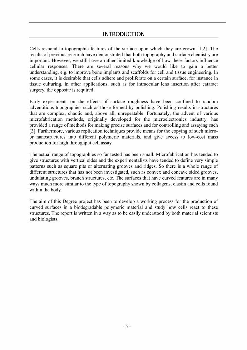
INTRODUCTION
Cells respond to topographic features of the surface upon which they are grown [1,2]. Theresults of previous research have demonstrated that both topography and surface chemistry areimportant. However, we still have a rather limited knowledge of how these factors influencecellular responses. There are several reasons why we would like to gain a betterunderstanding, e.g. to improve bone implants and scaffolds for cell and tissue engineering. Insome cases, it is desirable that cells adhere and proliferate on a certain surface, for instance intissue culturing, in other applications, such as for intraocular lens insertion after cataractsurgery, the opposite is required.
Early experiments on the effects of surface roughness have been confined to randomadventitious topographies such as those formed by polishing. Polishing results in structuresthat are complex, chaotic and, above all, unrepeatable. Fortunately, the advent of variousmicrofabrication methods, originally developed for the microelectronics industry, hasprovided a range of methods for making precise surfaces and for controlling and assaying each[3]. Furthermore, various replication techniques provide means for the copying of such micro-or nanostructures into different polymeric materials, and give access to low-cost massproduction for high throughput cell assay.
The actual range of topographies so far tested has been small. Microfabrication has tended togive structures with vertical sides and the experimentalists have tended to define very simplepatterns such as square pits or alternating grooves and ridges. So there is a whole range ofdifferent structures that has not been investigated, such as convex and concave sided grooves,undulating grooves, branch structures, etc. The surfaces that have curved features are in manyways much more similar to the type of topography shown by collagens, elastin and cells foundwithin the body.
The aim of this Degree project has been to develop a working process for the production ofcurved surfaces in a biodegradable polymeric material and study how cells react to thesestructures. The report is written in a way as to be easily understood by both material scientistsand biologists.

- 6 -
THEORY
Micromachining
Micromachining, or microfabrication, describes one of many precision engineering techniquesfor creating small three-dimensional structures with dimensions ranging from subcentimetersto submicrometers. Such tiny structures are used in, for example, sensors and integratedcircuits. In short, basic micromachining involves lithography and etching.
LithographyLithography is the technique used for transferring copies of a master pattern onto the surfaceof a solid material. The master can then be re-used to make many identical copies rather thanbeing consumed directly. Here the most widely used form of lithography is described:photolithography.
In photolithography, a plane surface covered with a thin layer of a light sensitive polymer, aso-called photoresist, is illuminated through a mask and then developed (fig. 1).
Figure 1. In photolithography, a surface covered with resist is illuminated through amask and developed.
The mask is a glass or quartz plate with a metal (e.g. a 500 Å thick chromium layer) patterndescribing the outlines for the structures to be fabricated. It is placed above the resist surfaceand as light (of wavelengths depending on the resist used) is shone through it, the pattern istransferred to the surface in the form of a latent image. The image is developed by, forexample, immersion of the surface in a developing solution (e.g. acetone). Depending on thenature of the resist, the image can be either the same as the metal mask pattern or its inverse.The resist is either positive or negative in its reaction to the illumination. Positive resists areweakened (breaks are induced in the main and side polymer chains) by light of the appropriatewavelengths and exposed areas become more soluble in developing solutions. Negativeresists, on the other hand, are strengthened (cross-linkage of main and side polymer chains) inthe exposed areas and thus become less soluble. Either way, the surface is now covered with apattern of resist that will protect it from etchant in the etching step [4].
EtchingBy different etching procedures one aims at removing material from the resist-patternedsurface in different ways to obtain different results. Here I will only briefly describe two of thepossible etching processes even though there are many more and much more to be said aboutthe two I’ve chosen to discuss.
- 7 -
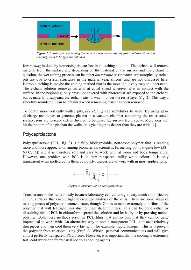
Figure 2. In isotropic wet etching, the material is removed equally fast in all directions andsmoothly rounded edges are obtained.
Wet etching is done by immersing the surface in an etching solution. The etchant will removematerial from the surface and depending on the material of the surface and the etchant inquestion, the wet etching process can be either anisotropic or isotropic. Anisotropically etchedpits are due to crystal structures in the material (e.g. silicon) and are not discussed here.Isotropic etching is maybe the etching method that is the most intuitively easy to understand.The etchant solution removes material at equal speed wherever it is in contact with thesurface. In the beginning, only areas not covered with photoresist are exposed to the etchant,but as material disappears, the etchant eats its way in under the resist layer (fig. 2). This way asmoothly rounded pit can be obtained when remaining resist has been removed.
To obtain more vertically walled pits, dry etching can sometimes be used. By using glowdischarge techniques to generate plasma in a vacuum chamber containing the resist-coatedsurface, ions are to some extent directed to bombard the surface from above. More ions willhit the bottom of the pit than the walls, thus yielding pits deeper than they are wide [4].
Polycaprolactone
Polycaprolactone (PCL, fig. 3) is a fully biodegradable, non-toxic polymer that is rendingmore and more appreciation among biomaterials scientists. Its melting point is quite low (58 -60°C, [5]) and it is therefore soft and easy to work with at room and body temperature.However, one problem with PCL is its non-transparent milky white colour. It is onlytransparent when melted but is then, obviously, impossible to work with in most applications.
Figure 3. Structure of ε-polycaprolactone.
Transparency is desirable mostly because laboratory cell culturing is very much simplified byculture surfaces that enable light microscope analysis of the cells. There are some ways ofmaking pieces of polycaprolactone clearer, though. One is to make extremely thin films of thepolymer that will let light pass due to their sheer thinness. This can be done either bydissolving bits of PCL in chloroform, spread the solution and let it dry or by pressing meltedpolymer. Both these methods result in PCL films that are so thin that they can be quiteimpractical to work with. An alternative way to obtain transparent PCL is to melt relativelythin pieces and then cool them very fast with, for example, liquid nitrogen. This will preventthe polymer from re-crystallizing (Prof. A. Wirsén, personal communication) and will givealmost perfectly transparent PCL pieces. However, it is important that the cooling is extremelyfast; cold water or a freezer will not do as cooling agents.
OCH2 5
n
O
- 8 -
Cell cytoskeleton
Eukaryotic (with nucleus) cells possess an interior network of filamentous proteins to supporttheir inner and outer structure. This flexible and dynamic construction is called thecytoskeleton and enables the cell to adopt different shapes and move in a coordinated fashionas well as to organise the many components in its interior. Unlike our own bony skeleton, thecytoskeleton doesn't just constitute the "bones" of the cell but also the "muscles" as it isdirectly responsible for the cell movements along surfaces.
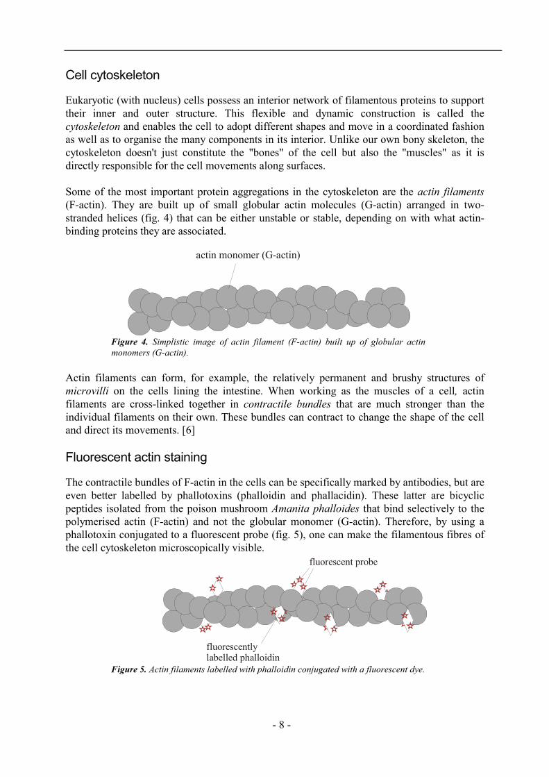
Some of the most important protein aggregations in the cytoskeleton are the actin filaments(F-actin). They are built up of small globular actin molecules (G-actin) arranged in two-stranded helices (fig. 4) that can be either unstable or stable, depending on with what actin-binding proteins they are associated.
Figure 4. Simplistic image of actin filament (F-actin) built up of globular actinmonomers (G-actin).
Actin filaments can form, for example, the relatively permanent and brushy structures ofmicrovilli on the cells lining the intestine. When working as the muscles of a cell, actinfilaments are cross-linked together in contractile bundles that are much stronger than theindividual filaments on their own. These bundles can contract to change the shape of the celland direct its movements. [6]
Fluorescent actin staining
The contractile bundles of F-actin in the cells can be specifically marked by antibodies, but areeven better labelled by phallotoxins (phalloidin and phallacidin). These latter are bicyclicpeptides isolated from the poison mushroom Amanita phalloides that bind selectively to thepolymerised actin (F-actin) and not the globular monomer (G-actin). Therefore, by using aphallotoxin conjugated to a fluorescent probe (fig. 5), one can make the filamentous fibres ofthe cell cytoskeleton microscopically visible.
Figure 5. Actin filaments labelled with phalloidin conjugated with a fluorescent dye.
fluorescentlylabelled phalloidin
fluorescent probe
actin monomer (G-actin)
- 9 -
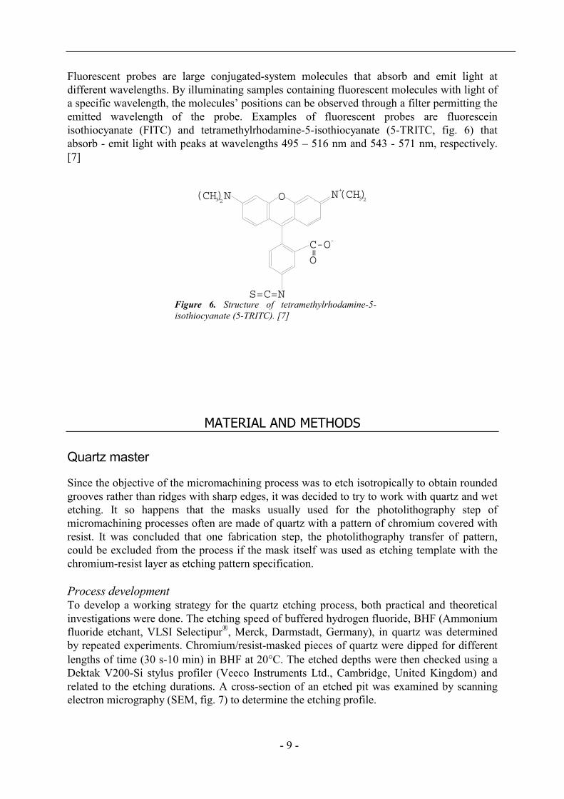
Fluorescent probes are large conjugated-system molecules that absorb and emit light atdifferent wavelengths. By illuminating samples containing fluorescent molecules with light ofa specific wavelength, the molecules’ positions can be observed through a filter permitting theemitted wavelength of the probe. Examples of fluorescent probes are fluoresceinisothiocyanate (FITC) and tetramethylrhodamine-5-isothiocyanate (5-TRITC, fig. 6) thatabsorb - emit light with peaks at wavelengths 495 – 516 nm and 543 - 571 nm, respectively.[7]
Figure 6. Structure of tetramethylrhodamine-5-isothiocyanate (5-TRITC). [7]
MATERIAL AND METHODS
Quartz master
Since the objective of the micromachining process was to etch isotropically to obtain roundedgrooves rather than ridges with sharp edges, it was decided to try to work with quartz and wetetching. It so happens that the masks usually used for the photolithography step ofmicromachining processes often are made of quartz with a pattern of chromium covered withresist. It was concluded that one fabrication step, the photolithography transfer of pattern,could be excluded from the process if the mask itself was used as etching template with thechromium-resist layer as etching pattern specification.
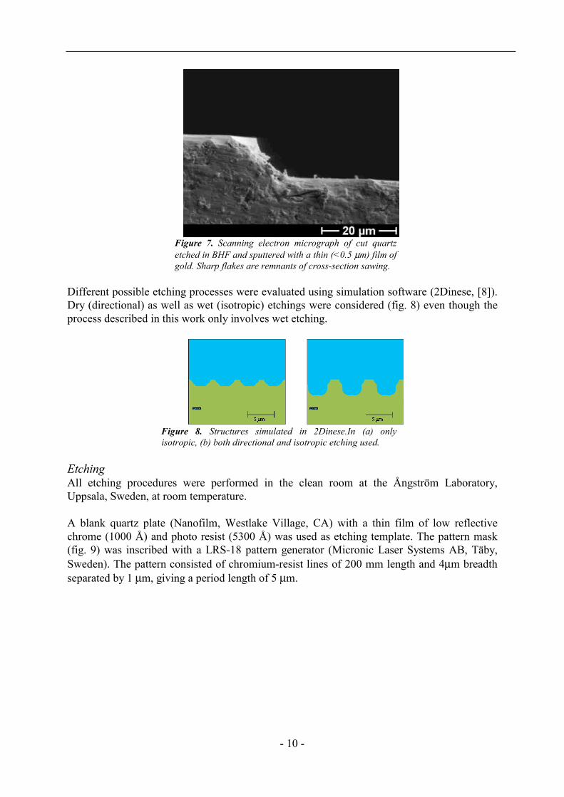
Process developmentTo develop a working strategy for the quartz etching process, both practical and theoreticalinvestigations were done. The etching speed of buffered hydrogen fluoride, BHF (Ammoniumfluoride etchant, VLSI Selectipur®, Merck, Darmstadt, Germany), in quartz was determinedby repeated experiments. Chromium/resist-masked pieces of quartz were dipped for differentlengths of time (30 s-10 min) in BHF at 20°C. The etched depths were then checked using aDektak V200-Si stylus profiler (Veeco Instruments Ltd., Cambridge, United Kingdom) andrelated to the etching durations. A cross-section of an etched pit was examined by scanningelectron micrography (SEM, fig. 7) to determine the etching profile.
N(CH)(CH)N O
S=C=N
C-O
=
O
2 23 3
+
-
- 10 -
Figure 7. Scanning electron micrograph of cut quartzetched in BHF and sputtered with a thin (<0.5 µm) film ofgold. Sharp flakes are remnants of cross-section sawing.
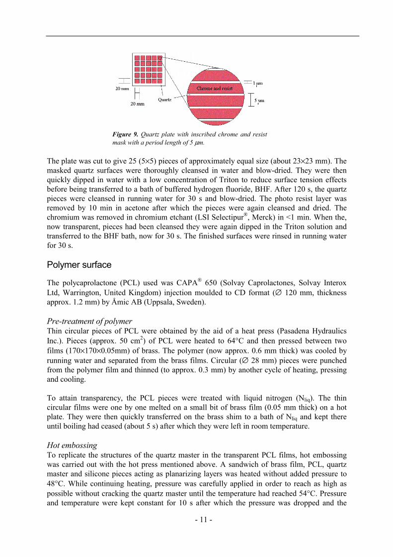
Different possible etching processes were evaluated using simulation software (2Dinese, [8]).Dry (directional) as well as wet (isotropic) etchings were considered (fig. 8) even though theprocess described in this work only involves wet etching.
Figure 8. Structures simulated in 2Dinese.In (a) onlyisotropic, (b) both directional and isotropic etching used.
EtchingAll etching procedures were performed in the clean room at the Ångström Laboratory,Uppsala, Sweden, at room temperature.
A blank quartz plate (Nanofilm, Westlake Village, CA) with a thin film of low reflectivechrome (1000 Å) and photo resist (5300 Å) was used as etching template. The pattern mask(fig. 9) was inscribed with a LRS-18 pattern generator (Micronic Laser Systems AB, Täby,Sweden). The pattern consisted of chromium-resist lines of 200 mm length and 4µm breadthseparated by 1 µm, giving a period length of 5 µm.
- 11 -
Figure 9. Quartz plate with inscribed chrome and resistmask with a period length of 5 µm.
The plate was cut to give 25 (5×5) pieces of approximately equal size (about 23×23 mm). Themasked quartz surfaces were thoroughly cleansed in water and blow-dried. They were thenquickly dipped in water with a low concentration of Triton to reduce surface tension effectsbefore being transferred to a bath of buffered hydrogen fluoride, BHF. After 120 s, the quartzpieces were cleansed in running water for 30 s and blow-dried. The photo resist layer wasremoved by 10 min in acetone after which the pieces were again cleansed and dried. Thechromium was removed in chromium etchant (LSI Selectipur®, Merck) in <1 min. When the,now transparent, pieces had been cleansed they were again dipped in the Triton solution andtransferred to the BHF bath, now for 30 s. The finished surfaces were rinsed in running waterfor 30 s.
Polymer surface
The polycaprolactone (PCL) used was CAPA® 650 (Solvay Caprolactones, Solvay InteroxLtd, Warrington, United Kingdom) injection moulded to CD format (∅ 120 mm, thicknessapprox. 1.2 mm) by Åmic AB (Uppsala, Sweden).
Pre-treatment of polymerThin circular pieces of PCL were obtained by the aid of a heat press (Pasadena HydraulicsInc.). Pieces (approx. 50 cm2) of PCL were heated to 64°C and then pressed between twofilms (170×170×0.05mm) of brass. The polymer (now approx. 0.6 mm thick) was cooled byrunning water and separated from the brass films. Circular (∅ 28 mm) pieces were punchedfrom the polymer film and thinned (to approx. 0.3 mm) by another cycle of heating, pressingand cooling.
To attain transparency, the PCL pieces were treated with liquid nitrogen (Nliq). The thincircular films were one by one melted on a small bit of brass film (0.05 mm thick) on a hotplate. They were then quickly transferred on the brass shim to a bath of Nliq and kept thereuntil boiling had ceased (about 5 s) after which they were left in room temperature.
Hot embossingTo replicate the structures of the quartz master in the transparent PCL films, hot embossingwas carried out with the hot press mentioned above. A sandwich of brass film, PCL, quartzmaster and silicone pieces acting as planarizing layers was heated without added pressure to48°C. While continuing heating, pressure was carefully applied in order to reach as high aspossible without cracking the quartz master until the temperature had reached 54°C. Pressureand temperature were kept constant for 10 s after which the pressure was dropped and the
- 12 -
sandwich immediately cooled in running water. The sandwich was parted and the master usedagain in other embossing cycles. The completed replicas in PCL (now about 0.15 mm thick)were kept at room temperature.
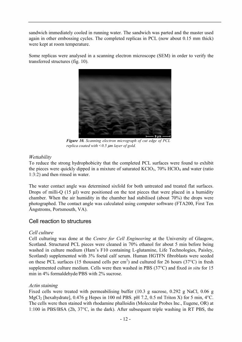
Some replicas were analysed in a scanning electron microscope (SEM) in order to verify thetransferred structures (fig. 10).
Figure 10. Scanning electron micrograph of cut edge of PCLreplica coated with <0.5 µm layer of gold.
WettabilityTo reduce the strong hydrophobicity that the completed PCL surfaces were found to exhibitthe pieces were quickly dipped in a mixture of saturated KClO3, 70% HClO4 and water (ratio1:3:2) and then rinsed in water.
The water contact angle was determined sixfold for both untreated and treated flat surfaces.Drops of milli-Q (15 µl) were positioned on the test pieces that were placed in a humiditychamber. When the air humidity in the chamber had stabilised (about 70%) the drops werephotographed. The contact angle was calculated using computer software (FTA200, First TenÅngstroms, Portsmouth, VA).
Cell reaction to structures
Cell cultureCell culturing was done at the Centre for Cell Engineering at the University of Glasgow,Scotland. Structured PCL pieces were cleaned in 70% ethanol for about 5 min before beingwashed in culture medium (Ham’s F10 containing L-glutamine, Life Technologies, Paisley,Scotland) supplemented with 3% foetal calf serum. Human HGTFN fibroblasts were seededon these PCL surfaces (15 thousand cells per cm2) and cultured for 26 hours (37°C) in freshsupplemented culture medium. Cells were then washed in PBS (37°C) and fixed in situ for 15min in 4% formaldehyde/PBS with 2% sucrose.
Actin stainingFixed cells were treated with permeabilising buffer (10.3 g sucrose, 0.292 g NaCl, 0.06 gMgCl2 [hexahydrate], 0.476 g Hepes in 100 ml PBS. pH 7.2, 0.5 ml Triton X) for 5 min, 4°C.The cells were then stained with rhodamine phalloidin (Molecular Probes Inc., Eugene, OR) at1:100 in PBS/BSA (2h, 37°C, in the dark). After subsequent triple washing in RT PBS, the
- 13 -
PCL surface with cells was mounted on a glass slide for analysis. Micrographs were obtainedwith a Vickers M17 (no longer made) fluorescence microscope (abs. ∼540 nm, em. ∼570 nm)and a Hamamatsu Argus camera and frame grabber.
RESULTS AND DISCUSSION
Structured surfaces in PCL
The etching speed of BHF in quartz was determined to 10 nm/s through repeated experiments.The quality of the etched surfaces (smoothness of edges) was found to be highly dependent onthe cleanness of the etchant solution. If the BHF was more than one week old (BHF bathrefilled more than one week ago), it was common to see large crystal-like disturbances in theetched areas. To avoid this, the BHF was refilled before every new etching occasion.
The structures obtained through wet isotropic etching of quartz and subsequent replications inpolycaprolactone showed to be very much like the ones that had been simulated (compare fig.8a and 10). The profile of the grooves turned out almost exactly as the simulations and thedepth is (by inspection of fig. 10) at least close to the 1.25 µm that had been simulated. Eventhough the ridges look a bit rough in the SEM micrograph, light micrographs (not included)showed no such coarseness. It is quite probable that the bumps and scratches seen in the SEMmicrograph are due to the crudeness of the pre-SEM cutting of the PCL piece.
Pre-treatment of the polymer was aimed to yield transparent pieces suitable for cell culturing.One major problem was that the replication method involved a heating step that could annulthe earlier liquid nitrogen treatment by once again melting the polymer structure. To avoid thishappening, the hot embossing was carried out at a temperature below the PCL melting point.However, when examining the final cell culturing pieces, one could see that the transparencywas no longer as perfect as it had been before the hot embossing step. Considering that thethickness of the polymer pieces had also been noticeably reduced, one could argue that theliquid nitrogen treatment could have been annulled. Contradicting this hypothesis is, though,the fact that earlier embossings at higher temperatures with untreated PCL never showed asgood transparency as the treated ones, after all, did.
Wettability analysis
The results of the contact angle measurements are shown in table I.
Table IContact angles (degrees) of water droplets on flat PCL surfaces, before and
after wettability treatmentContact angle,
untreatedStandarddeviation
Contact angle,treated
Standarddeviation
- 14 -
76 2 53 2The contact angles are clearly smaller for the treated surfaces than the untreated ones. Thehandling is obviously helpful in cases like these where a hydrophobic surface has to be treatedquickly.
It should be noted that the untreated surfaces in table I were not as extremely hydrophobic asthe pieces that were treated in Glasgow before cell seeding were. Unlike the Glasgowsurfaces, the wettability analysis pieces were not at all too hard to submerge in water beforetreatment. This is corroborated by the contact angle values (table I) that are not extremelyhigh, either. There is no direct explanation to why the pieces were so different. The onlydifference in the way they had been treated (they were made the same day and transported toScotland in the same box) is the actual site of investigation. The contact angle measurementswere performed at the Biomedical Centre, Uppsala, but the first hydrophobicity observationswere made at Centre for Cell Engineering, Glasgow. Supporting this theory of locationimportance is the fact that the pieces of PCL used in cell culture trials (results not included inthis report) during the first couple of days in Glasgow did not show any sign of extraordinaryhydrophobicity that other pieces did later (after about a week). However, the exact reasons tothe effect remain to be investigated.
Cell reaction
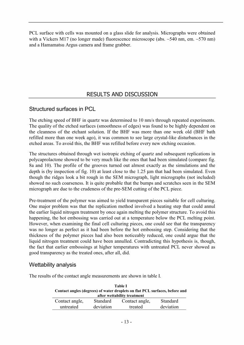
Human HGTFN fibroblasts showed distinct alignment to the grooves of the PCL surface assoon as they had settled and adhered to the surface (4-5 h). With fluorescent staining (26 h),actin bundles could be seen to stretch along the surface (fig. 11).
Figure 11. Fluorescence light micrograph of human HGTFN cells on grooved PCLsurface. Cells are stained with rhodamine phalloidin. Groove direction ishorizontal.
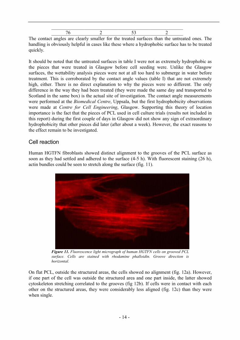
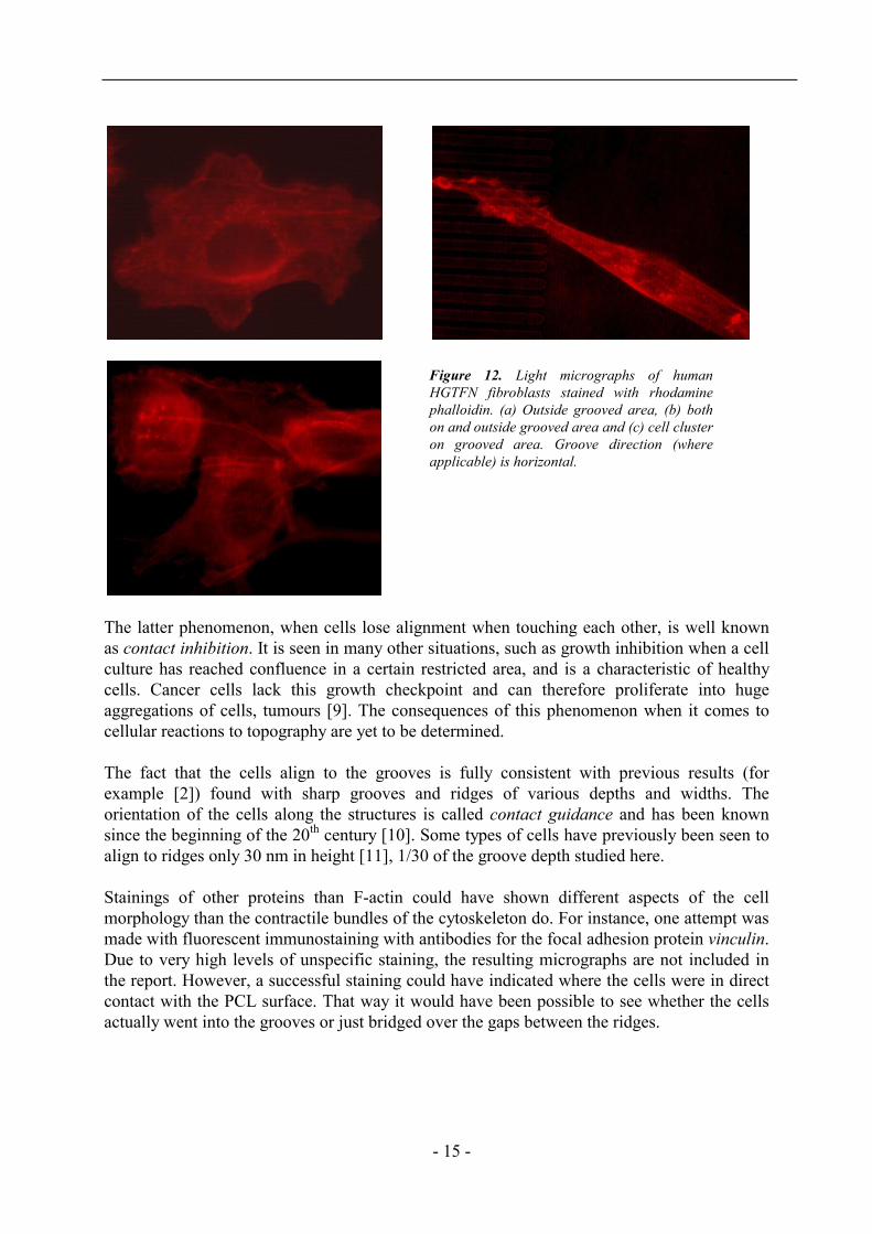
On flat PCL, outside the structured areas, the cells showed no alignment (fig. 12a). However,if one part of the cell was outside the structured area and one part inside, the latter showedcytoskeleton stretching correlated to the grooves (fig 12b). If cells were in contact with eachother on the structured areas, they were considerably less aligned (fig. 12c) than they werewhen single.
- 15 -
The latter phenomenon, when cells lose alignment when touching each other, is well knownas contact inhibition. It is seen in many other situations, such as growth inhibition when a cellculture has reached confluence in a certain restricted area, and is a characteristic of healthycells. Cancer cells lack this growth checkpoint and can therefore proliferate into hugeaggregations of cells, tumours [9]. The consequences of this phenomenon when it comes tocellular reactions to topography are yet to be determined.
The fact that the cells align to the grooves is fully consistent with previous results (forexample [2]) found with sharp grooves and ridges of various depths and widths. Theorientation of the cells along the structures is called contact guidance and has been knownsince the beginning of the 20th century [10]. Some types of cells have previously been seen toalign to ridges only 30 nm in height [11], 1/30 of the groove depth studied here.
Stainings of other proteins than F-actin could have shown different aspects of the cellmorphology than the contractile bundles of the cytoskeleton do. For instance, one attempt wasmade with fluorescent immunostaining with antibodies for the focal adhesion protein vinculin.Due to very high levels of unspecific staining, the resulting micrographs are not included inthe report. However, a successful staining could have indicated where the cells were in directcontact with the PCL surface. That way it would have been possible to see whether the cellsactually went into the grooves or just bridged over the gaps between the ridges.
Figure 12. Light micrographs of humanHGTFN fibroblasts stained with rhodaminephalloidin. (a) Outside grooved area, (b) bothon and outside grooved area and (c) cell clusteron grooved area. Groove direction (whereapplicable) is horizontal.
- 16 -
CONCLUSIONS AND FUTURE WORK
The cell culturing and staining done in this work show that human fibroblasts align in muchthe same way to smoothly grooved substrata as they do to ridges with sharp corners of thesame dimensions. This was suspected. However, what would be interesting to investigate infuture work is if the cells in any aspect react differently to smooth grooves. The genesexpressed, the proteins produced and the strength of adhesion to the structures could very wellbe functions where the reactions may differ. Intuitively one would guess that the surfaces thatthe cells encounter in the human body are more similar to smooth groves than to sharp cornersand that the reactions would therefore be more “body like” on smooth grooves.
Apart from comparing reactions to smooth grooves and sharp ridges of the same dimensions,smooth grooves of different lengths of period and amplitudes should be compared to eachother. It has earlier been shown [12] that cells react differently depending on how high theridges are and their frequency. This should therefore be thoroughly investigated for smoothgrooves as well. For instance, the smallest influencing groove depth could possibly bedifferent with rounded corners instead of sharp ones.
Another aspect that should be studied is if cells differentiate differently on different structures.The implications for such reactions could be very important for implant surface structuring inthe future. For instance, bone implants could maybe be incorporated better in the body if cellsin contact with the implant developed into bone cells. Alternatively, differentiated cells inlaboratory cultures could be kept on structured surfaces suited especially for their kind. As itis today, laboratory culture dishes used for in vitro experiments are the only flat surfaces thatcells encounter. They are also the only kind used to study how cells react to varioustreatments, even though they cannot provide a biologically normal environment for the cells.
Many properties of polycaprolactone are often coveted enough to compensate for its lack oftransparency. However, for PCL to become widely used in laboratories better methods tomake it clear have to be developed. Even though working with opaque materials is possible, itis definitely more time consuming. Commercially produced Petri dishes for laboratory workare most often made in other, transparent, polymeric materials such as polystyrene (PS) orpolypropylene (PP). These plastics do not possess the biodegradability of PCL, though, andare therefore not suitable for, for example, tissue engineering.

- 17 -
ACKNOWLEDGEMENTS
I want to express my deepest gratitude to all who have helped and encouraged me during myproject work, both in Uppsala and in Glasgow. I am especially grateful to my supervisors Ass.Professors Eva Pålsgård and Fredrik Nikolajeff. Your enthusiasm and interest in the projecthave been truly inspirational to me and I really appreciate the ease of our contacts. I also wishto thank Professor Adam Curtis, University of Glasgow, for the warm welcome and generoushelp given to me during my visit in March 2001.
I am also grateful to all the people at the Materials Science Division for introducing me to allthe various machines and microscopes. And, of course, for the coffee break, lunch and dinnerdiscussions!
Thank you:
Malin Svedberg, for introducing me to clean room techniques and all the extra help you havegiven me throughout the year. You are my star!
Thomas Björk, for showing me what Ph D studentship is all about and enduring mycomputer’s aeroplane noise.
Professor Anders Wirsén (Royal Institute of Technology, Stockholm, Sweden), for helping meout in times of polymer need.
Elena Martines, for making my stay in Glasgow unforgettable and wonderful!
Finally, I want to thank my wonderful friends and family for always being there. I love youall!
- 18 -
REFERENCES
1. CURTIS, A. S. G. AND WILKINSON, C. D. W. (1998) Reactions of cells to topography, J.Biomaterials Sci. Polymer, 9, 1313-1329
2. CURTIS, A. AND WILKINSON, C. (1997) Topographical control of cells, Review,Biomaterials 18, 1573-1583
3. SCHWEITZ, J. –Å., LARSSON, K., THORNELL, G., BJÖRKMAN, H. AND NIKOLAJEFF, F.(2000) New materials and new proceses for MEMS applications, Mat. Res. Soc. Symp.Proc., 605, 57-72
4. MADOU, M. J., (1997) Fundamentals of microfabrication, CRC Press LLC, Boca Raton,FL
5. SOLVAY CAPROLACTONES. “Safety information, CAPA® Polycaprolactone” Nov 1999.http://www.caprolactones.com/SafetyInfo/SafetySheet/CAPA-650_s.htm (22 May 2001)
6. ALBERTS, B., BRAY, D., JOHNSON, A., LEWIS, J., RAFF, M., ROBERTS, K. AND WALTER,P. (1998) Essential Cell Biology: An Introduction to the Molecular Biology of the Cell,Garland Publishing Inc., New York, NY
7. MOLECULAR PROBES INC. “Handbook of Fluorescent Probes and Research Products,probes for Actin” May 2001. http://www.probes.com/handbook/sections/1101.html (22May 2001)
8. KATARDJIEV, I. V., CARTER, G., NOBES, M. J., BERG, S. AND BLOM, H. O. (1994) Three-dimensional simulation of surface evolution during growth and erosion, J. Vac. Sci.Technol. A, 12, 61-68
9. COOPER, G. M. (1997) The cell: a molecular approach, ASM Press, Washington, DC,Sinauer Associates, MA
10. VON RECUM, A. F., SHANNON, C. E., CANNON, C. E., LONG, K. J., VAN KOOTEN, T. G.AND MEYLE, J. (1996) Surface roughness, porosity, and texture as modifiers of cellularadhesion, Tissue Engineering, 2, 241-253
11. WOICIAK-STOTHARD, B., CURTIS, A., MONAGHAN, W., MACDONALD, K. ANDWILKINSON, C. (1996) Guidance and activation of murine macrophages by nanometricscale topography, Exp. Cell Res., 223, 426-435
12. WALBOOMERS, X. F., MONAGHAN, W., CURTIS, A. S. G. AND JANSEN, J. A. (1999)Attachment of fibroblasts on smooth and microgrooved polystyrene, J. Biomed. Mat.Res. 46, 212-220