current status of near surface disposal … documents/waste... · chakwal, mianwali & dg khan...
TRANSCRIPT

1
Directorate General National Repository
Pakistan Atomic Energy Commission
PAEC-IAEA National Workshop on Strategy and Methodologies for the Development of Near Surface Disposal Facilities
February 24-28, 2014, Islamabad
CURRENT STATUS OF NEAR SURFACE DISPOSAL PROGRAM IN PAKISTAN
Masood Akhter Deputy Chief Scientist

CONTENTS
Pakistan – An introduction Repository development program General site selection criteria Potential rocks/sites identification Summary
2
3
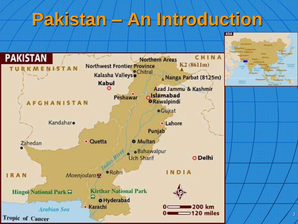
Pakistan – An Introduction
4
Pakistan
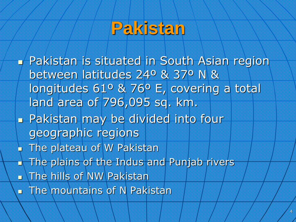
Pakistan is situated in South Asian region between latitudes 24º & 37º N & longitudes 61º & 76º E, covering a total land area of 796,095 sq. km.
Pakistan may be divided into four geographic regions
The plateau of W Pakistan
The plains of the Indus and Punjab rivers
The hills of NW Pakistan
The mountains of N Pakistan

5
Pakistan (continued)
Himalayas, Hindukush and Karakuram mountain Ranges meet in the Northern Pakistan.
In rest of the country there is a belt of sub-mountain Potwar plateau and Salt range, western bordering highlands the Balochistan plateau and southern Indus plain.
The country shares its borders with Iran to the West, India in the Southeast, Afghanistan in the Northwest, and China in the North.
6
Pakistan (continued)
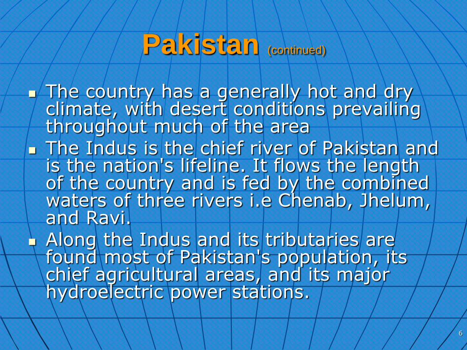
The country has a generally hot and dry climate, with desert conditions prevailing throughout much of the area
The Indus is the chief river of Pakistan and is the nation's lifeline. It flows the length of the country and is fed by the combined waters of three rivers i.e Chenab, Jhelum, and Ravi.
Along the Indus and its tributaries are found most of Pakistan's population, its chief agricultural areas, and its major hydroelectric power stations.
7
Pakistan (continued)
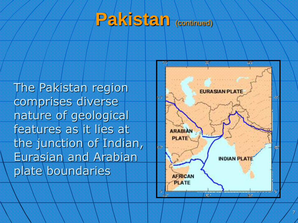
The Pakistan region comprises diverse nature of geological features as it lies at the junction of Indian, Eurasian and Arabian plate boundaries

8
Major tectonic trends on and around the northwest part
of the Indo-Pakistan subcontinents

Disposal
WHAT IS DISPOSAL?
Emplacement of radioactive waste in a disposal
system (repository):-
• with reasonable assurance for safety
• without the intention of retrieval
• without reliance on long-term surveillance and maintenance
9

Objective
To isolate radioactive waste from the
biosphere for a long period of time to
protect human health, environment now and
in the future without imposing undue
burdens on future generations
10
Disposal Facilities Development
Program
Development of a disposal facility is a big task
International waste disposal programmes reveals that granite, salt and clay formations act as favorable hosts
11
There are three phases associated with the lifetime of a disposal facility which are;
Pre-operational
Operational
Closure & Post-closure
12
The pre-operational phase includes the necessary siting studies
Siting of radioactive waste disposal facilities is an important step in developing a waste disposal system that would best suit the needs for accommodation of wastes from a national nuclear programme and simultaneously satisfy all relevant safety, technical and environmental requirements set out in various national and international guidelines
13

Siting Process for Near Surface
Disposal Facility
The set of all activities (up to construction of disposal facility) towards development of disposal facilities/repositories is termed as siting-process
Siting process is a step-by-step activity and following are the main stages;
Conceptual & planning stage
Area survey stage
Site characterization stage
Site conformation stage
Suitable disposal sites are selected against predefined siting criteria
14

Site Selection Criteria There are general guidelines that govern the site
selection criteria, mainly from the viewpoint of safety, while non-safety related considerations are also necessary and these include social and economic impacts
Exclusion criteria
Exclusion criteria have to be selected taking into account of several geographical, environmental, socio-economic, sociopolitical and technical constraints
Site(s) falling in exclusion criteria should not be considered for further work
The exclusion criteria is based taking into account of both technical and non technical attributes
15
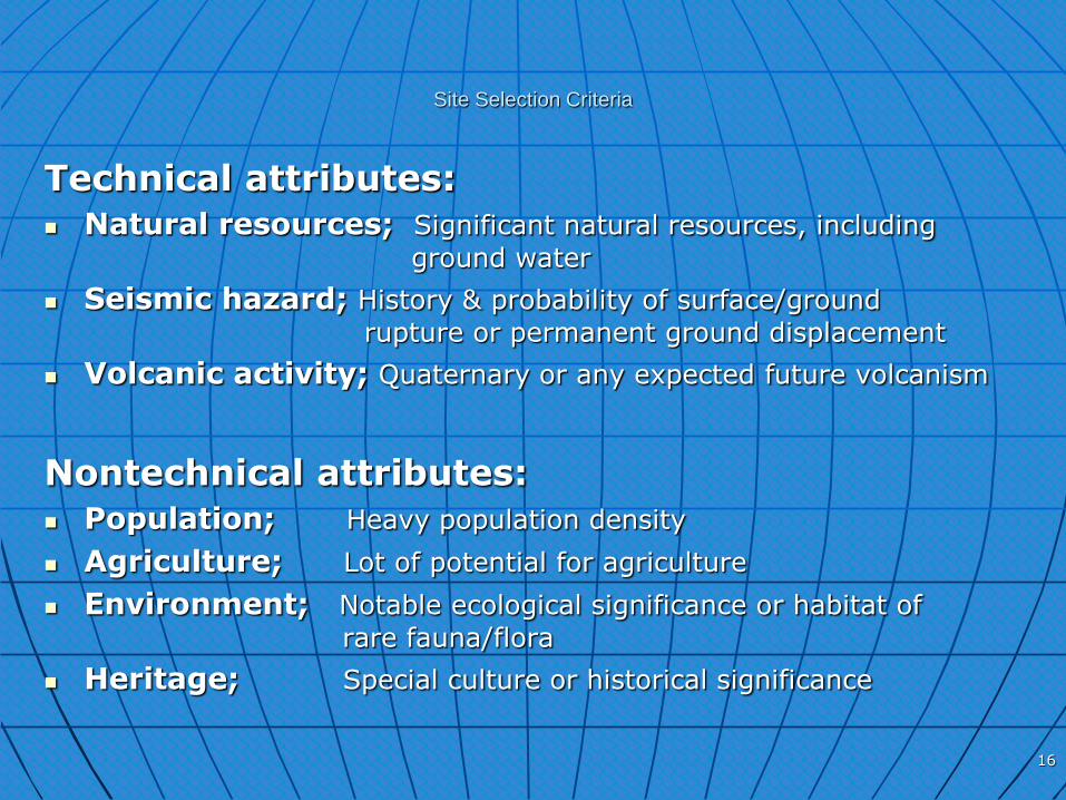
Site Selection Criteria
Technical attributes:
Natural resources; Significant natural resources, including
ground water
Seismic hazard; History & probability of surface/ground
rupture or permanent ground displacement
Volcanic activity; Quaternary or any expected future volcanism
Nontechnical attributes:
Population; Heavy population density
Agriculture; Lot of potential for agriculture
Environment; Notable ecological significance or habitat of
rare fauna/flora
Heritage; Special culture or historical significance
16

Site Selection Criteria
Apart from the exclusion criteria following are the basis which should be considered for the establishment of Site Selection Criteria
Technical attributes:
Geology; rock type, rock mass, dip & strike of strata etc.
Geotectonic; faults, folds, fractures etc.
Geomorphology; slopes/relief, soil, drainage pattern etc.
Hydrogeology; surface & ground water, flooding etc.
Seismicity; seismic hazard analysis, seismogenic structures etc.
Climate; temperature, wind speed/direction, humidity etc.
Rainfall; precipitation, evaporation etc.
17
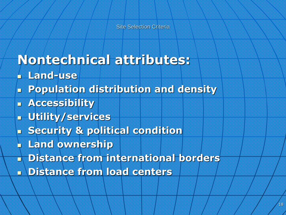
Site Selection Criteria
Nontechnical attributes: Land-use
Population distribution and density
Accessibility
Utility/services
Security & political condition
Land ownership
Distance from international borders
Distance from load centers
18

Disposal Facility - Pakistan
Almost 90% of radioactive waste produced in Pakistan fall in LILW-SL category and mostly contain short lived radionuclides and low concentrations of long lived radionuclides
Such type of wastes is suitable for disposal in Near Surface Disposal Facility (NSDF)
19

Status of Disposal Facilities in Pakistan
Activity Near Surface
Disposal Facility
Deep Geological
Repository
Siting Process In-progress Planning
Facility Development
- -
20

Near Surface Disposal Facilities
(NSDF)
Near-surface disposal facilities are facilities located at the surface of the ground or at depths down to several tens of meters below the surface
21
NSDF
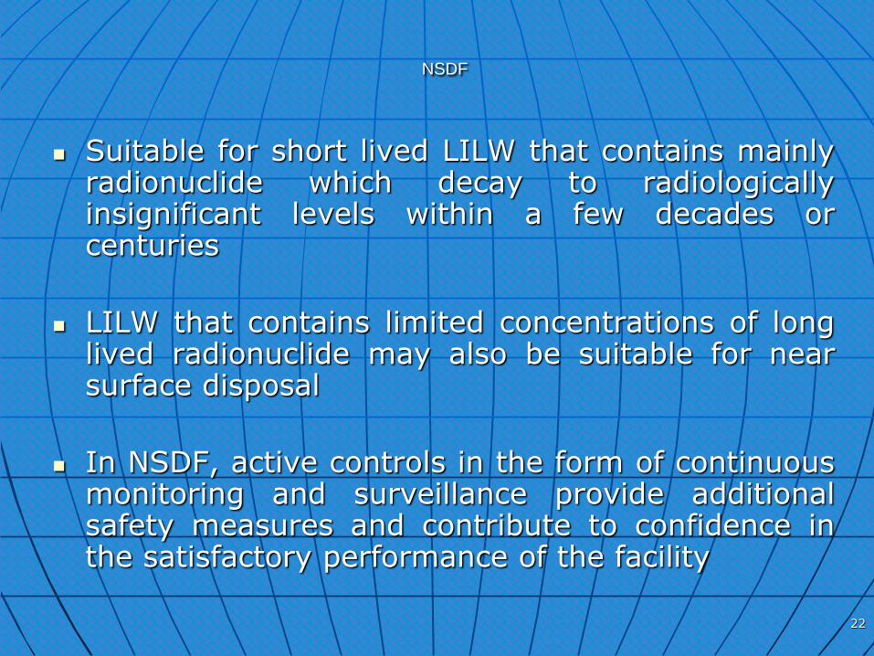
Suitable for short lived LILW that contains mainly
radionuclide which decay to radiologically insignificant levels within a few decades or centuries
LILW that contains limited concentrations of long lived radionuclide may also be suitable for near surface disposal
In NSDF, active controls in the form of continuous monitoring and surveillance provide additional safety measures and contribute to confidence in the satisfactory performance of the facility
22

NSDF
All NSDF concepts rely on a system of passive barriers (multi-barrier concept) to prevent, or very drastically delay, the transport of radionuclides into the biosphere
The barriers are combination of engineered and natural barriers
Isolation from the biosphere is provided by placing several barriers between the waste materials and the external environment, arranged in succession so that each barrier reinforces the preceding one
23
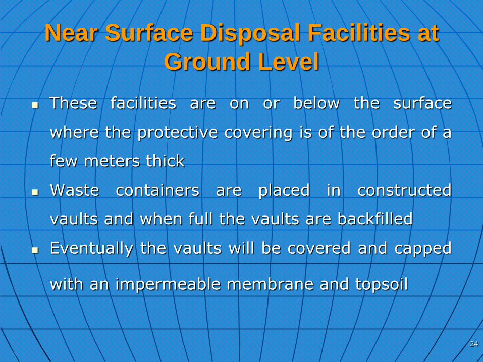
Near Surface Disposal Facilities at
Ground Level
These facilities are on or below the surface
where the protective covering is of the order of a
few meters thick
Waste containers are placed in constructed
vaults and when full the vaults are backfilled
Eventually the vaults will be covered and capped
with an impermeable membrane and topsoil
24

Near Surface Disposal Facilities in
Caverns Below Ground Level
These facilities require under ground excavation of caverns conducted from surface
Such facilities are at a depth of several tens of meters below the earth's surface and accessed through a drift
Near surface disposal facilities are typically used for LLW and ILW with a radionuclide content of short half-life (up to about 30 years)
25
Engineered, NSDF
Typically capacity thousands of cubic meter
Ease of waste emplacement
26

NSDF - Pakistan
All kinds of rocks (e.g. sedimentary, metamorphic and igneous) are present in the stratigraphic sequence of Pakistan
Due to unstable political as well seismo-tectonic conditions we have to focus on risk-free or least venturous regions of the country
In conceptual planning stage, 39 sites/formations from the stratigraphic sequence of Pakistan were studied for evaluation of their initial potential for the disposal of various type of radioactive waste
27

Initially survey of 11 sites/areas in Chakwal, Mianwali & DG Khan regions have been completed
Detail site characterization studies at Dhok Miani-Nara Site is in progress
28

To Sakesar
To Mianwali
To Talagang
LAWA
38 P/14
N
East of Dhok Miani Area,Distt.Chakwal,
Grid reference; N 32° 36' & E 71° 54' (38-P/14)
29
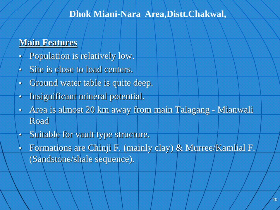
Dhok Miani-Nara Area,Distt.Chakwal,
Main Features
• Population is relatively low.
• Site is close to load centers.
• Ground water table is quite deep.
• Insignificant mineral potential.
• Area is almost 20 km away from main Talagang - Mianwali
Road
• Suitable for vault type structure.
• Formations are Chinji F. (mainly clay) & Murree/Kamlial F.
(Sandstone/shale sequence).
30
NSDF – Pakistan
Modular, Vault type surface disposal facility- under consideration
31

Planning for proposed NSDF
Facility will be used for disposal of solid and solidified LILW-SL
Facility will be built in tectonically stable/safe area
Facility will be designed well above the level of water table in order to provide protection from ground water infiltration, with the provision of impermeable base & walls (concrete)
Facility will be built outside the range of any possible flooding & higher than any level possible reached by the water table
Facility will remain under institutional control during the surveillance period and repair can be made if necessary
Intentional human intrusion will be precluded
Isolation of waste from plants, animals and erosive forces will be determined by the quality of engineered barriers and site characteristics
NSDF – Pakistan
32
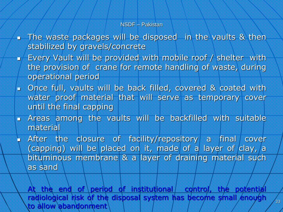
NSDF – Pakistan
The waste packages will be disposed in the vaults & then stabilized by gravels/concrete
Every Vault will be provided with mobile roof / shelter with the provision of crane for remote handling of waste, during operational period
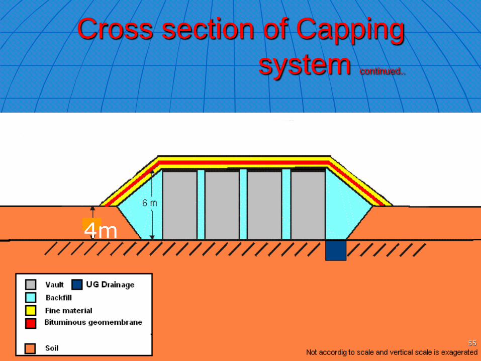
Once full, vaults will be back filled, covered & coated with water proof material that will serve as temporary cover until the final capping
Areas among the vaults will be backfilled with suitable material
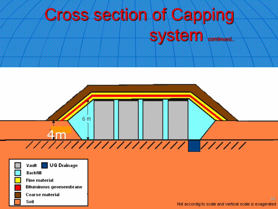
After the closure of facility/repository a final cover (capping) will be placed on it, made of a layer of clay, a bituminous membrane & a layer of draining material such as sand
At the end of period of institutional control, the potential radiological risk of the disposal system has become small enough to allow abandonment
33
Procedure
Proposed waste disposal procedure at NSDF
NSDF will receive LILW-SL, NPPs waste in
immobilized/over-packed in specially designed (according
to WAC requirement) RCC boxes or barrels
Interim storage
Disposal in NSDF
34

1100
900
100
100
13mm Ø C/C 150mm
13mm Ø C/C 100mm
1- M.S Liner 2mm thick
2- 1:2:4 Baryte concrete
3- 13mm Ø M.S bars for R.C.C
4- 25.4mm Ø M.S bolt for lifting
1400
1300
IndexDate M o d i f i c a t i o n s
07-08-09
RCC CONCRETE BARREL
(WMD-SC-RCC-T200)
Designed by:
Mian Ahmad Syed, SEChecked by:
M. Aslam Nasir, PEApproved by:
Drawn by:
Mian Ahmad Syed, SE
Unit:
Scale: 1:12.5
DC-03-1024WMDWASTE MANAGEMENT DIVISION
WMD/ CAD /
TITLE
DWG. NO.
Format:
Folio:
REF.
Remarks
LEGEND
12
34
RCC CONCRETE BARREL
TOP VIEWS
CONCRETE DETAILSREINFORCEMENT DETAILS AA
A
DETAIL B
B
ISOMETRIC VIEW150
Ø1100
Ø1000
Ø80
0
Ø70
0
200
700
150
M 24
S.No Description Details
1 1:2:4Concrete Ratio
2
3
4
5
6
7
9
8
Water cement ratio 0.53
M.S. Reinforcemant
M.S Liner
Volume of Concrete
Empty Weight (Ton)
0.123 Ton
0.048 Ton
815 L
2.70 to 2.80
Tolerence ( H, OD, ID)
Crushing strength (psi)
±10, ±5, ±10
3600 - 4200
Surface Finish MouldA
25
25
DETAIL A
90
90
DGNFC, PAEC, ISLAMABD
35

IndexDate M o d i f i c a t i o n s
21-08-09
RCC BARREL (OUTER DIMENSIONS)
Designed by:
Mian Ahmad Syed, SEChecked by:
M. Aslam Nasir, PEApproved by:
Drawn by:
Mian Ahmad Syed, SE
Unit:
Scale: 1:12.5
WMD-RCC-BB-700WMDWASTE MANGEMENT DIVISION
DGNFC, PAEC, ISLAMABADWMD / CAD /
TITLE
DWG. NO.
Format:
Folio:
REF.
Remarks
10
0
100
1100
900
14
00
Note: All dimensions are in mm
36

U- Channels(MS 125x125x1500)
Angle Iron (37x37x1500)Angle Iron (37x37x1500)
50
MS- RODS (Ø10mm)
525-550
DETAIL C
C
125 125
50
100
MS-PLATE (5x150x150)
MS-PLATE (5x100x150)
50
100
50
100
MS- RODS (Ø10mm)
Note: All dimensions are in mm
PCC 1:2:4
PCC 1:2:4
300 300300 300U- Channels(MS 125x125x1500)
80 80
Designed by:M. Aslam Nasir, PE
Drawn by: Mian Ahmad Syed, SE
OVER PACK FOR 4-MS.DRUMS(200L)
Remarks
REF.
Folio:
Format:
DWG. NO.
TITLE
WMD / CAD /
WASTE MANGEMENT DIVISION
DGNFC, PAEC, ISLAMABAD
WMD WMD-MS-OP-200L
Scale: 1:1
Unit:
Approved by:Checked by:
6-04-10
M o d i f i c a t i o n sDate Index
50
100
MS-Sheet 16 SWG(1.6mm)
MS-Sheet 16 SWG (1.6mm)
80
900-950
Lifting HooksWelded(Ø20 mm)
DETAIL B
B
1200±50
100
1050-1100
1500±100
1500±100
TOP VIEWMS-Sheet 16 SWG(1.6mm)
AA
SECTION AASECTION AA
80
A A
MS-Drum (200L)
MS-Sheet 16 SWG (1.6mm)
TOP VIEW
1500±100
1500±100
80
1050-1100
MS-STRIP FOR REINFORCEMENT (3x50) MS-STRIP FOR REINFORCEMENT (3x50)
37

SECTION A-A
FRONT VIEW
(REINFORCEMENT)
15
0
10
0
300
30
0
25
15
0
M.S deformed bars (vertical)
9-13mmØ@ 150mm c/c
M.
S (
Ho
rize
nta
l)
6-1
3m
mØ
@ 2
00
mm
c/c
38
100
AA
TOP VIEWLegs
(REINFORCEMENT)
BOTTOM VIEW
1500
1001300100
15
00
10
0
150
15
0
ANNEXURE-1A
CAP
10
0
25
25
19
13mm@150mm c/c
(b/w)
8-13mmØ@150mm c/c
(b/w)
7-13mm @150mm c/c
15
0
13mm@150mm c/c
30
0
300300
30
0
8-13mmØ@150mm c/c
8-13mmØ@150mm c/c
1260
300
100
300
100
HOOKS ALONG
THE WALL(typ)
CASING FOR EYE BOLT
38
ANGLE IRON
1½"X1½"X 316"
3-13mm Ø
300
100
300
100
910
DatedDrawing No. S-1/3
Designed By Drawn by
NR-OP-02-R
RCC Over Pack Container for 4-MS Drums
NR/DGNFCM.Aslam Nasir
Approved by
Manzur Hussain
DCE,DGNR
DG, NR
Tanveer Ahmad (PE)
(WASO)
ANGLE IRON
1½"X1½"X 316"
AT ALL BOTTOM CORNERS(TYPICAL)
ANGLE IRON
1½"X1½"X 316"
B
3-13mm Ø
ANGLE IRON
1½"X1½"X 316"
AT ALL BOTTOM CORNERS(TYPICAL)
DETAIL OF B
ANGLE IRON TO BEWELDED WITH NEAR BYSTEEL BARS (TYPICAL)
Reviewed by
1-3/8" Ø
1-3/8" Ø
6-1
3m
m Ø
@ 2
00
C/C
6-13mm Ø@ 200C/C
140
250
250
200
200
AKHLAQ AHMAD(TECH-1)
13
00
140
10
0
38
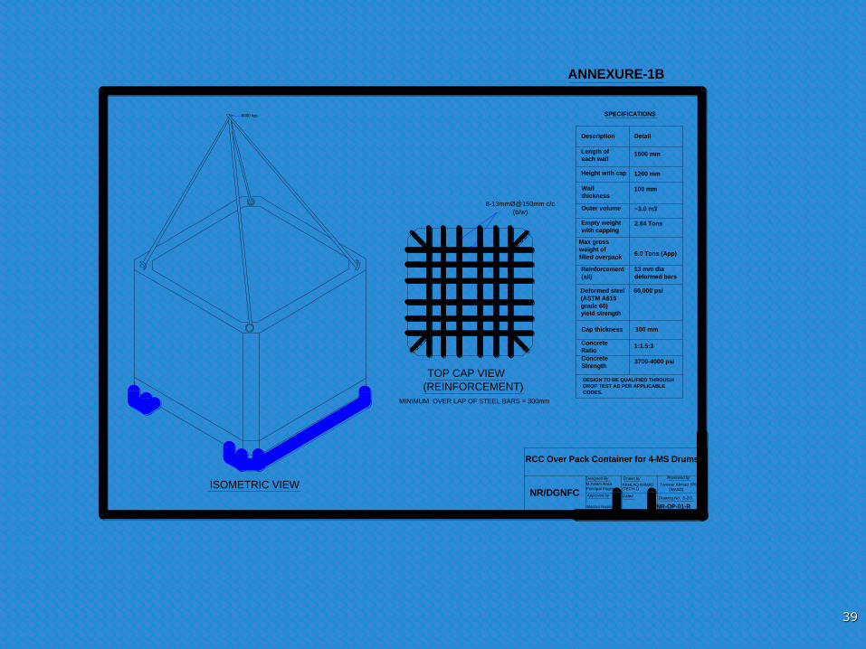
(REINFORCEMENT)
TOP CAP VIEW
ANNEXURE-1B
8-13mmØ@150mm c/c
(b/w)
ISOMETRIC VIEWDated
Drawing No. S-2/3
Designed By Drawn by
NR-OP-01-R
RCC Over Pack Container for 4-MS Drums
NR/DGNFCM.Aslam Nasir
Approved by
Manzur Hussain
Principal Engineer
Director, WM
Tanveer Ahmad (PE)
(WASO)
Description Detail
Reinforcement
(all)
13 mm dia
deformed bars
Concrete
Ratio1:1.5:3
Concrete
Strength3700-4000 psi
SPECIFICATIONS
Deformed steel
(ASTM A615
grade 60)
yield strength
60,000 psi
Length of
each wall1500 mm
Height with cap 1260 mm
Wall
thickness100 mm
Outer volume ~3.0 m3
Empty weight
with capping2.84 Tons
Max gross
weight of
filled overpack6.0 Tons (App)
Cap thickness 100 mm
DESIGN TO BE QUALIFIED THROUGH
DROP TEST AS PER APPLICABLE
CODES.
6000 kgs
Reviewed by
MINIMUM OVER LAP OF STEEL BARS = 300mm
AKHLAQ AHMAD(TECH-1)
39

Proposed Repository Design Vault Proposed size of Vault - 20x60x7 m Volume of single Vault - 20x60x7 m = 8400 m3
Area of single vault - 20x60 m = 1200 m2
RAW package (5 stacks) in single vault No. of RCC boxes in single vault - 12x36x5 = 2160 No. of RCC Barrels in single vault - 16x48x5 = 3840 Three Vaults can accommodate the annual RAW produced from “C” type reactors
40
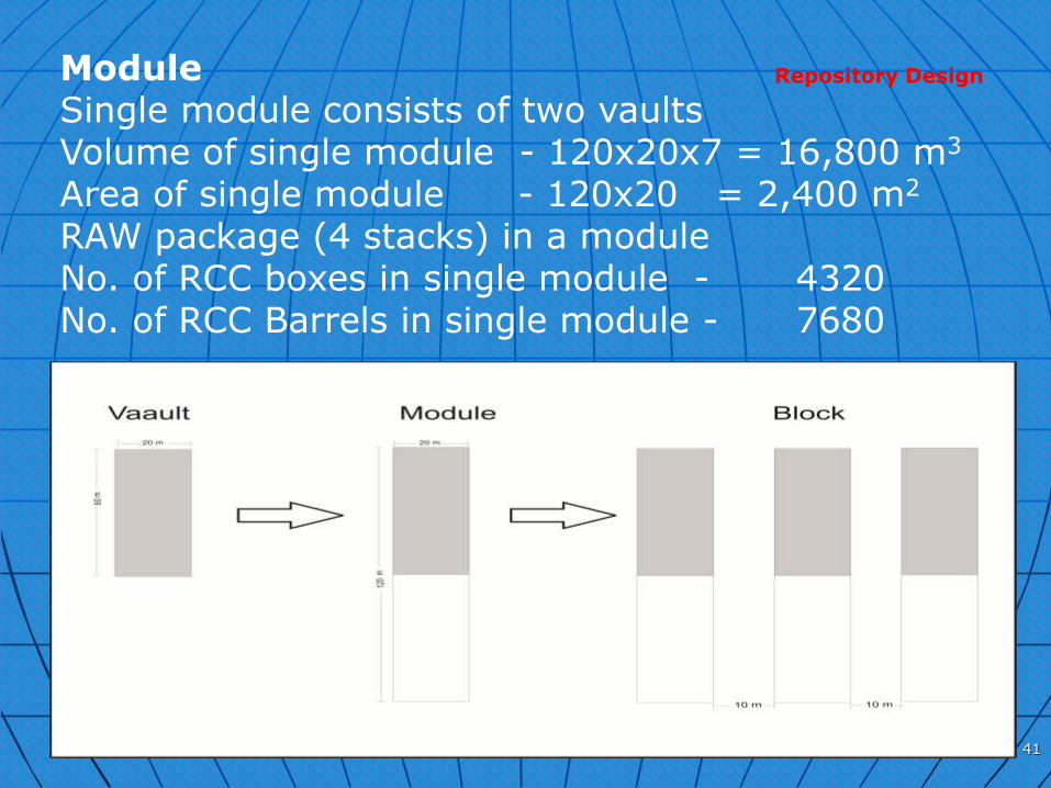
Module Single module consists of two vaults Volume of single module - 120x20x7 = 16,800 m3 Area of single module - 120x20 = 2,400 m2 RAW package (4 stacks) in a module No. of RCC boxes in single module - 4320 No. of RCC Barrels in single module - 7680
DGNR
Repository Design
41
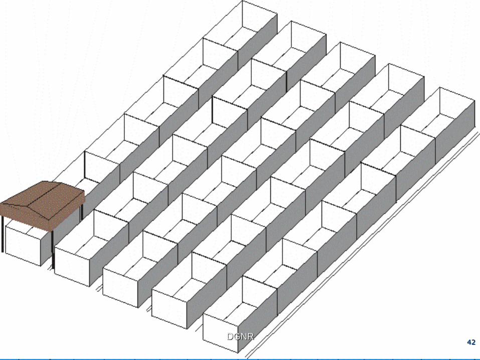
42 DGNR
42
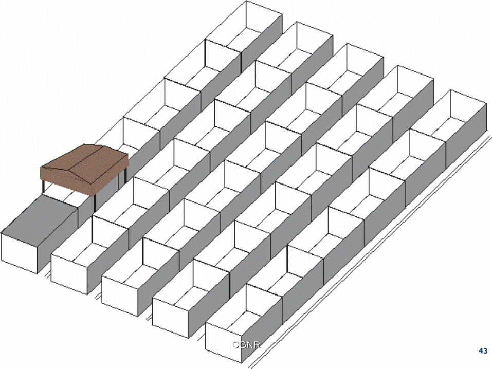
43 DGNR
43
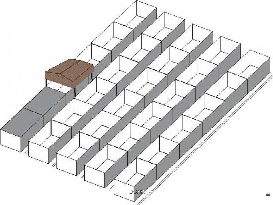
44 DGNR
44

45 DGNR
45
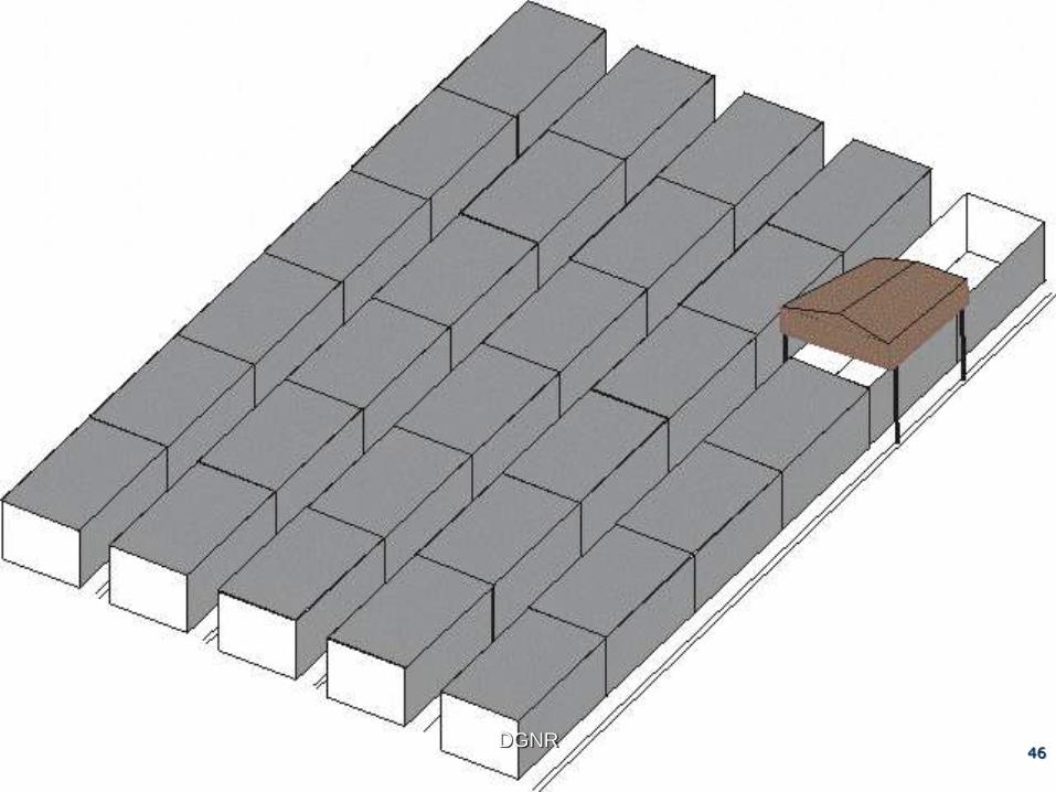
46 DGNR
46

47 DGNR
47

48

Cross section of Capping
system
49

Cross section of Capping system continued..
4m
50
Cross section of Capping
system continued..
4m
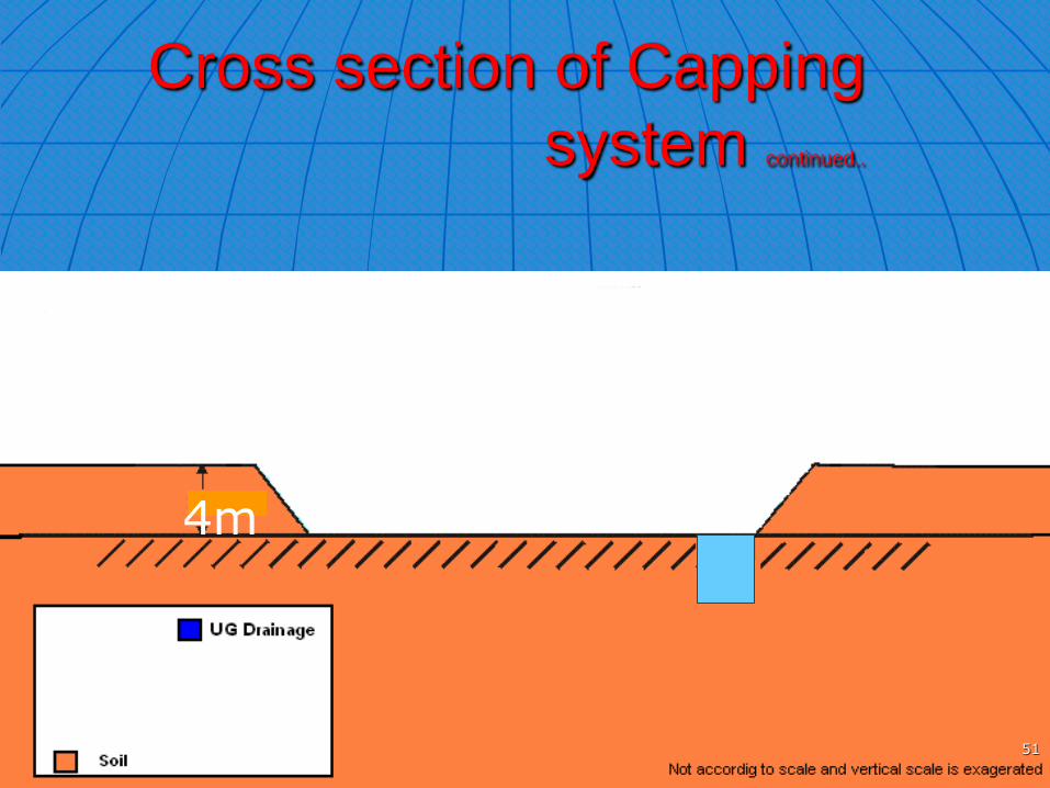
51

Cross section of Capping
system continued..
4m
52
Cross section of Capping
system continued..
4m
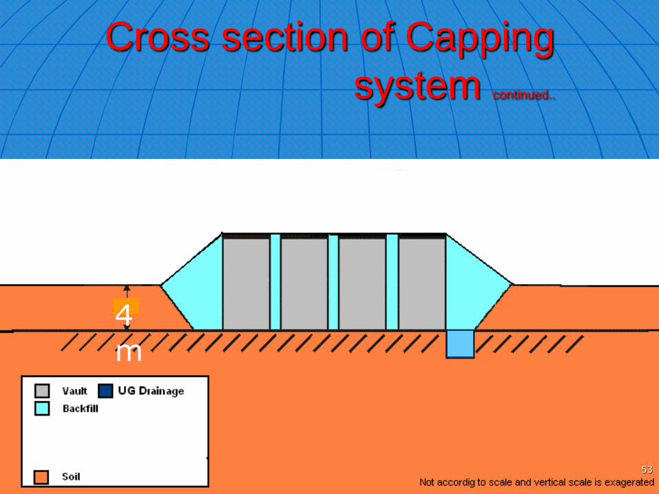
53

Cross section of Capping
system continued..
4m
54
Cross section of Capping
system continued..
4m
55
Cross section of Capping
system continued..
4m
56

Cross section of Capping
system continued..
4m
57
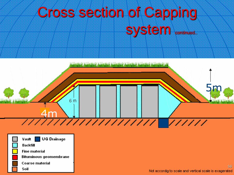
Cross section of Capping
system continued..
4m
5m
58
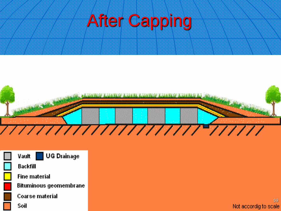
After Capping
59 59
60 60
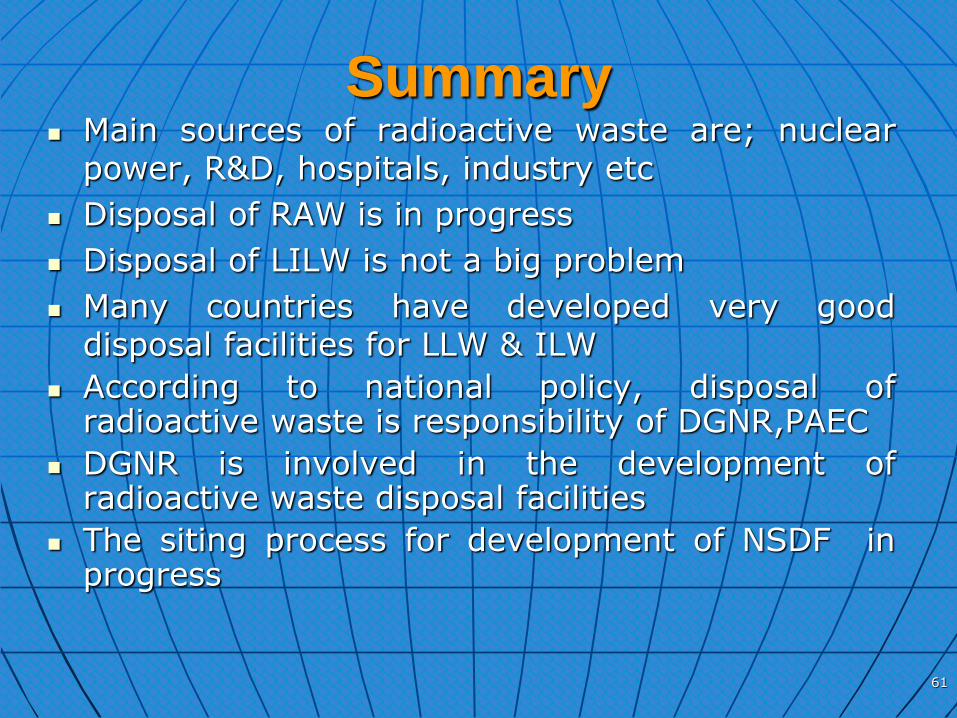
Main sources of radioactive waste are; nuclear power, R&D, hospitals, industry etc
Disposal of RAW is in progress
Disposal of LILW is not a big problem
Many countries have developed very good disposal facilities for LLW & ILW
According to national policy, disposal of radioactive waste is responsibility of DGNR,PAEC
DGNR is involved in the development of radioactive waste disposal facilities
The siting process for development of NSDF in progress
Summary
61

62