current research in current-driven magnetization dynamics s. zhang, university of missouri-columbia...
TRANSCRIPT

Current research in current-driven magnetization dynamics
S. Zhang, University of Missouri-Columbia
Beijing, Feb. 14, 2006

Outlines
Magentoelectronics started from discovery of giant magnetoresistive (GMR) effect
Spin-dependent transport in magnetic metal based nanostructures
Spin angular momemtum transfer: physics and potential technology
Perspectives and conclusions

M.N. Baibich et al., Phys. Rev. Lett. 61, 2472 (1988).
400
110
H (kOe)-40 H // [ 0 11]
What is giant magnetoresistance?
R

Origin of GMR—two current model
e e e e
EF
A ferromagnet Different numbers ofup and down electrons
R R
Up and down resistances
Low resistance High resistance

GMR Reading head
Bit width
Bit length
Conductorlead
JM Spin
valve
Spin valve
OR MNMM
AF
“0”“1”

Concert efforts: theorists, experiments and technologists on GMR Theorists: predict, explain, model and design GMR
effects and devices
Experimentalists: design, fabricate, characterize, and measure GMR devices
Technologists: produce, evaluate, pattern, integrate, and deliver GMR devices
It would be otherwise impossible to push the information storage so rapidly

History of magentic tapes and hard disks
Now: 80Gbits/in2
5 years: 1 Terabits/in2
In 1988, giant Magnetoresistance (GMR) was discovered;in 1996, GMR reading heads were commercialized Since 2000: Virtually all writing heads are GMR heads

GND
Magnetoelectronics: Magnetic Tunnel Junctions
High tunneling probabilityLow resistance
Low tunneling probabilityHigh resistance
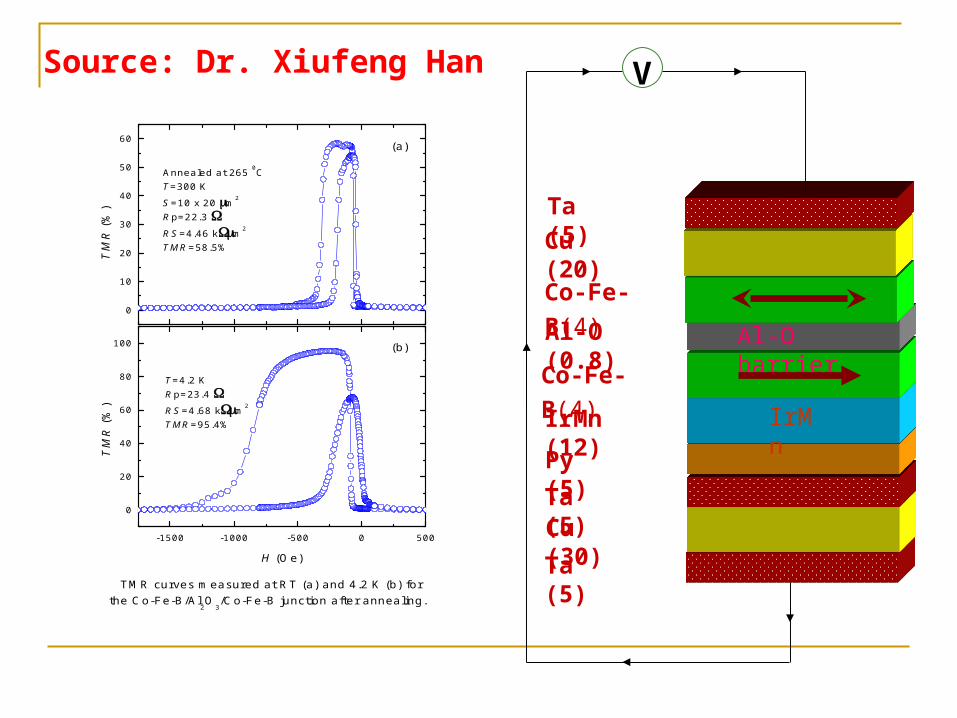
Al-O barrier
Cu (30)
IrMn
Co-Fe-B(4)
Ta (5)
IrMn (12)
Al-O (0.8)
Cu (20)
Ta (5)
Py (5)
Ta (5)
Co-Fe-B(4)
-1500 -1000 -500 0 500
0
20
40
60
80
100
0
10
20
30
40
50
60
T=4.2 KRp=23.4 RS=4.68 km2
TMR=95.4%
TM
R (
%)
H (Oe)
(b)
TMR curves measured at RT (a) and 4.2 K (b) for the Co-Fe-B/Al
2O
3/Co-Fe-B junction after annealing.
Annealed at 265 0CT=300 K
S=10 x 20 m2
Rp=22.3 RS=4.46 km2
TMR=58.5%
T
MR
(%
)
(a)
VSource: Dr. Xiufeng Han

Brief History of TMJ
1974, M. Julliere (a graduate student) published an experiment article which claimed 14% TMR in Fe/Ge/Fe trilayers. A simple model was proposed (the paper became a sleeping giant).
1982, IBM reported 2% TMR on Ni/AlO/Ni. 1995, Moodera (MIT) and Miyazaki (Japan) reported
10% TMR for Co/AlO/Co. 1998, DARPA launched MRAM solicitation 1999, Motorola’s 128kB MRAM demo 2003, IBM, Motolora, 4Mb MRAM chip demo More than 10 startup MRAM companies formed. MRAM becomes internationally recognized future
technology


Emerging non-volatile memory technologies
Flow
Spin
Quantity FRAM
PCRAM
MRAM
PFRAM SiC Bipolar
PMC
Molecular
Polymer Perovskite
NanoX’tal
3DROM

Current-driven spin torques
GMR/TMR: magnetization states control spin transport (low-high resistance).
Adverse effect: spin transport (spin current) affects magnetization states?
Every action will have reaction—spin transfer

T
spin angular momentum transfer? Momentum transfer—electromigration
Angular momentum transfer—magnetization dynamics
An impurity atom receives a force by absorbing a net momentum of electrons:electromigration is one of the major failure mechanisms in semiconductor devices.F
The atom receives a torque by absorbinga net spin angular momentum of electrons:the spin torque can be used for spintronics

Interaction between spin polarized current and magnetization (J. Slonczewski, IBM)
m mout in
m e Bout
m e Bin P
dMJ J
dt
J PJ Me
J PJ Me
MpM
Spin torque on the magnetic layer M
( )
/
J P
eJ B
dMa M M M
dt
a PJ e

0, 0
t t
Current torque on DW
(Magnetic field pressure on DW, )
0, 0t t
Massless motion!!
From Sadamichi Maekawa
Current induced Domain wall motion

Magnetization dynamics: LLG equation (micromagnetics)
1;| | | | 1; 1
( )
( )
( )
J P
J J
eff
eff
p
eff
b
a m m m
m mm m c m
x x
dm dmm H m
dt dtdm dm
m H mdt dt
m m V
E mH
m
LLG+spin torque
Where
Spin valve
Domain wall

Novelty of spin transfer torques
Manipulation of magnetization states by currents
Self-sustained steady state magnetization dynamics
Unusual thermal effects
Interesting domain wall dynamics
Dynamic phases: synchronization, modification and chaos

First observation of current induced magnetic switching by Spin torques
Co1=2.5nmCo2=6.0nm
Katine et. al., PRL (2000).

Self-sustained steady-states precession
2| | ( ) ( )eff J p p eff
dEm H a M m M m H
dt
The first term is always negative (damping), the second termcould be positive or negative (it even changes sign at different times).
Energy damping and pumping:
Limit cycle: the energy change is zero in an orbit
[ ( ) ( )] 0eff J pE
E dm m H a m m

Calculated limit cycles2 2 2sin cos 2 sin cosE K H

Kiselev et al., Nature (2003)
Experimental identification of limit cycles

Unusual Thermal effects
Eb
PAP
Neel-Brown relaxation:
( , )exp( / )b Bf T E E k T
( , )f T Mwhere is algebraic dependent on T, E
Question: in the presence of the spin torque, how do we formulatethe relaxation time?
Thermal activation
Difficulty: the spin torque is not conservative: ( )J p ma m m F m

LLG equation at finite temperatures
( ) ( ) ( )
0
( , ) ( ', ') 2 ( ') ( ')
eff J P
i jij
dm dmm H h m a m m m
dt dth
h r t h r t D r r t t
random field
( )
( )
eff m
eff
J p m
M
H E m
m H
a m m F m
Dm P
The magnetization receives following fields
Precessional conservative field
Non-conservative damping field
Non-conservative spin torque field
Diffusion field

Solution of Fokker-Planck equation
( ) [ ( ) ( )] ( ) 0eff J p ME E
B
P E dm m H a m m dm D P m
D k T
is diffusion constant (dissipation-fluctuation relation)
The probability energy density is:
'
'
( ) exp
( )
' ' ( ')( )
eff
B
J pE
effE Eeff
E
EP E A
k T
a dm m m
E E dE E dE C Edm m H
where

Experimental data interpretation
Telegraph noise
P
AP
P AP
P AP
H
P AP
J
P AP
J P AP
H+
J
R
Field alone Current alone
P AP
H

H-I phase boundary of equal dwell times.
Comparison with experiments
Equal dwell timesfor P and AP states
P AP
By simultaneously changingH and J, one can always have
( )(1 )bc
IE H Const
I

Synchronization, modification and chaos
Limit cycle
+ 1. Another oscillator2. AC external field3. AC external current
Linear oscillator

Calculated limit cycles2 2 2sin cos 2 sin cosE K H

Observation of synchronization by an AC current
Rippard et al, PRL (2005)

Observation of mutual synchronization
Kaka et al., Nature (2005); Mancoff et al, Nature (2005)
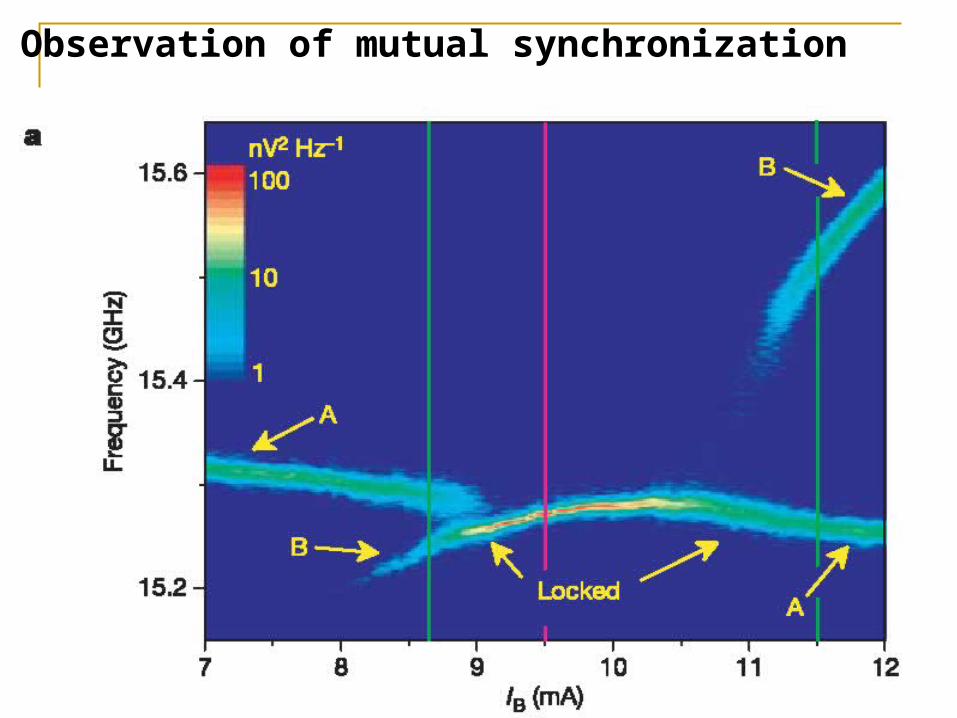
Observation of mutual synchronization

Narrower spectrum width at synchronization

Dynamic phases due to AC currents
M
M
M
M
20( )
0.02
200( )
0
aca Oe
H Oe
K

Synchronization spectrax1

Modification spectra (beating)
x2

Synchronization and modification agree well with experiments

Chaos spectrax3

Theories of spin torques in ferromagnets
Me Berger, domain drag force, based an intuitive physics picture
Bazaliy, et al,
Waintal and Viret, a global pressure and a periodic torque
Tatara and Kohno, spin transfer torque and momentum transfer torque.
Zhang and Li, adiabatic torque and non-adiabatic torques
Barnas and Maekawa, non-adiabatic torque relates to the damping of the adiabatic torque
within a ballistic transport model for half-metallic materials
MM M
x

Spin torques in a domain wall
1
ex s sf
m mJ m M
t M
�
Equation of motion for conduction electrons
( )e J Jff bM M
M H MM M
M M c Mx xt t
/ 0.01exJ J
sf
c b
where
Interaction between conduction electrons and magnetization:
ex
H m M

( , , )xm m x v t y z / /xm t v m x
If the wall is in steady motion, the current driven wall velocity is independent wall structure and pinning potentials
extJ
x
WHcv
ext ext xH H e
Steady state wall motion
Steady state wall velocity is thus
xss ejj
eff J J
m m m mm H m b m m c m
t t x x
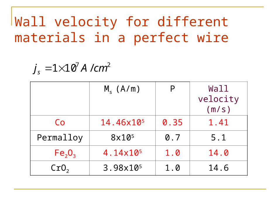
Wall velocity for different materials in a perfect wire
Ms (A/m) P Wall velocity (m/s)
Co 14.46x10⁵ 0.35 1.41
Permalloy 8x10⁵ 0.7 5.1
Fe2O3 4.14x10⁵ 1.0 14.0
CrO2 3.98x10⁵ 1.0 14.6
27 /101 cmAjs

Observed Domain wall motion in a nanowire
Yamagushi et al., PRL (2004)
Observed Wall velocity
8 2
3 /
1.2 10 /
v m s
j A cm
for

Vortex domain wall motion driven by current
05.0,01.0
/108 28
cmAje
Wall transition: from vortex all to transverse wall
xv
yv

Magnetic tunnel Junction
1 0
Goal: using a reasonable current to switch magnetization, ideally less than 106 A/cm2

Conductorlead
J
Oscillation of M (GHz) by a DC current
Application 2: local AC magnetic field oscillators (generators)
Local AC field (1000 Oe) with spatial resolution 10nm!

Application IV: concerns of CPP reading heads
Bit width
Bit length
Conductorlead
JM Spin
valve
“0”“1”
The large current density in CPPreading heads may produce unwanted switching!
Goal: eliminates current-inducedswitching for current densitylarger than 107A/cm2

Acknowledgement
Students: Dr. Yu-nong Qi, Mr. Zhao-yang Yang, Mr. Jie-xuan He
Postdoctoral: Dr. Z. Li (Postdoctoral)
Collaborators: P. M. Levy (NYU)
A. Fert (Orsay-Paris) Funded by: NSF-DMR, NSF-ECS, DARPA, NSFC