current leads for cryogenic systems - american...
TRANSCRIPT
Current Leads for Cryogenic Systems
P.O. Box 2509 • 112 Flint Road • Oak Ridge, TN 37831-2509Phone: (865) 482-1056 • Fax: (865) 482-5472
E-mail: [email protected]
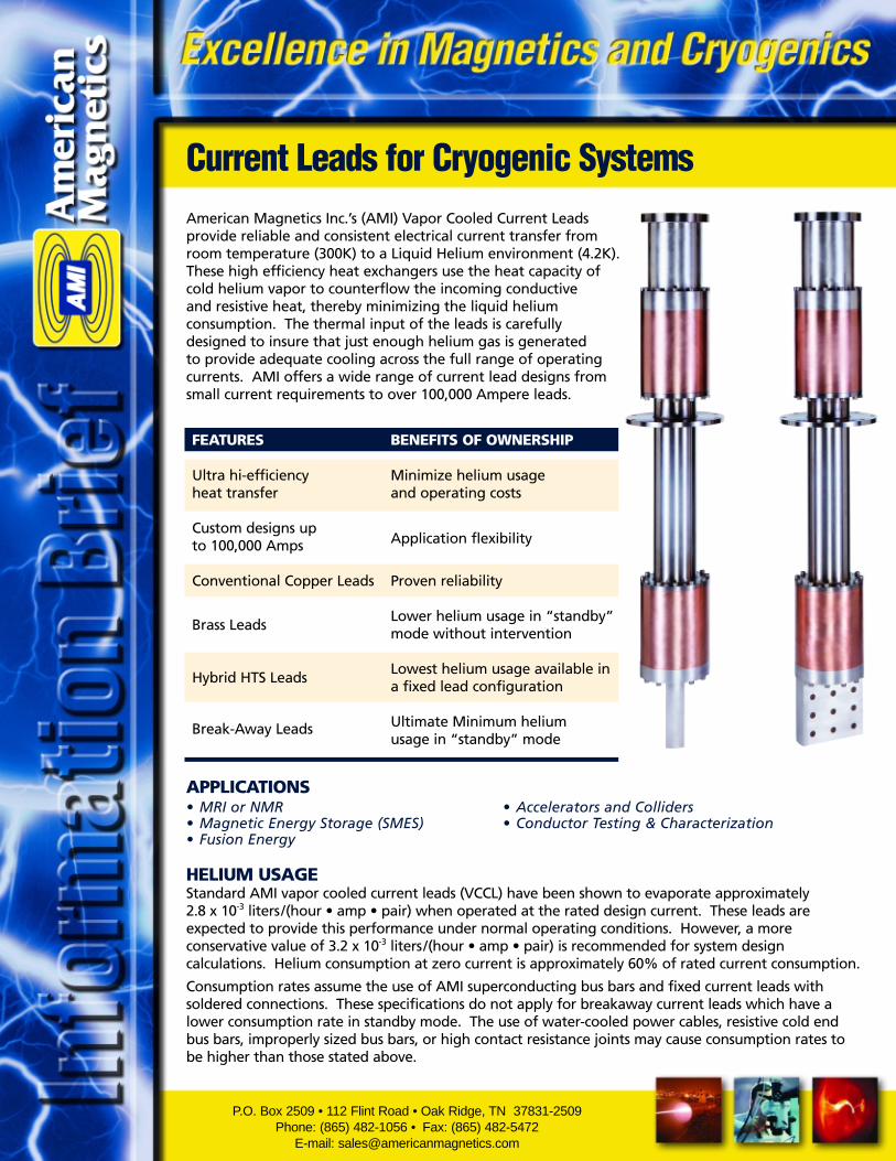
American Magnetics Inc.’s (AMI) Vapor Cooled Current Leadsprovide reliable and consistent electrical current transfer fromroom temperature (300K) to a Liquid Helium environment (4.2K).These high efficiency heat exchangers use the heat capacity ofcold helium vapor to counterflow the incoming conductive and resistive heat, thereby minimizing the liquid heliumconsumption. The thermal input of the leads is carefullydesigned to insure that just enough helium gas is generated to provide adequate cooling across the full range of operatingcurrents. AMI offers a wide range of current lead designs fromsmall current requirements to over 100,000 Ampere leads.
FEATURES BENEFITS OF OWNERSHIP
Ultra hi-efficiency Minimize helium usageheat transfer and operating costs
Custom designs up Application flexibilityto 100,000 Amps
Conventional Copper Leads Proven reliability
Lower helium usage in “standby” Brass Leads
mode without intervention
Lowest helium usage available in Hybrid HTS Leads
a fixed lead configuration
Ultimate Minimum helium Break-Away Leadsusage in “standby” mode
APPLICATIONS• MRI or NMR • Accelerators and Colliders • Magnetic Energy Storage (SMES) • Conductor Testing & Characterization• Fusion Energy
HELIUM USAGEStandard AMI vapor cooled current leads (VCCL) have been shown to evaporate approximately 2.8 x 10⁻³ liters/(hour • amp • pair) when operated at the rated design current. These leads areexpected to provide this performance under normal operating conditions. However, a moreconservative value of 3.2 x 10⁻³ liters/(hour • amp • pair) is recommended for system designcalculations. Helium consumption at zero current is approximately 60% of rated current consumption.
Consumption rates assume the use of AMI superconducting bus bars and fixed current leads withsoldered connections. These specifications do not apply for breakaway current leads which have alower consumption rate in standby mode. The use of water-cooled power cables, resistive cold endbus bars, improperly sized bus bars, or high contact resistance joints may cause consumption rates tobe higher than those stated above.

APPLICATION CONSIDERATIONS
VOLTAGE DIFFERENTIAL
AMI leads operate with a voltagedifferential of less than 100 mV asmeasured from the top of the lead tothe bottom, or 200 mV measuredbetween the leads on the warm end.Upon request, voltage tap attachmentpoints can be provided on all leadsizes. The measurement of this valuecan be a useful tool for detectinginsufficient gas flow or an overcurrentcondition. System trigger points canbe established to take correctiveaction or shut down the system priorto overheating of the leads forwhatever reason.
PRESSURE DIFFERENTIAL
A typical pressure differential ofapproximately 2 mm mercury (0.03psi) is developed through the leadswhen operating at their maximumrated current for standard leadlengths.
ICING & FROSTING
Depending upon the operatingconditions of the cryogenic system,frosting or icing on or around the topof the current lead may be observed.This may be caused by forcing morecold gas through the leads than isnecessary. A common example of this occurs when the background dewar boil-off gas is vented throughthe leads while in standby mode. Although small amounts of icing or moisture do not generally present aproblem, AMI can provide electrical heaters to keep the exposed lead above the freezing point. Specialconstruction techniques are also available to prevent O-rings from freezing on the cryostat mountingflanges.
CUSTOM INTERFACES
A number of different style interface points are available on current leads. The standard horizontal upperend tab can be rotated to the vertical ‘Flag’ position in cases where the leads must be mounted very closetogether. The warm end connection for power cables can be configured with special bolt patterns, largesurface area mounting surfaces for low contact resistance, or designed for a circular clamping typeconnection. Cold end connections are also highly adaptable to suit specific requirements.
Figure 1: Dimensional References for Standard Vapor Cooled Leads Up to 10,000Amperes

Model Number L-50 L-75 L-100 L-150 L-200 L-250 L-500 L-1000 L-2000 L-3000 L-5000 L-10000
Amperes 50 75 100 150 200 250 500 1000 2000 3000 5000 10000
Approx. HeliumConsumption, 0.16 0.24 0.32 0.48 0.64 0.8 1.6 3.2 6.4 9.6 16.0 32.0Liters/Hr.(pair of leads)
Type A A A A A A A B B B B B
A 1/4 1/4 1/4 1/4 3/8 3/8 1/2 1/2 1/2 1/2 3/4 3/4
B 1-1/2 1-1/2 1-1/2 1-1/2 2 2 3 3 3 3-3/4 4-1/2 7
C 1 1 1 1 1-1/4 1-1/4 1-1/2 2 2-1/2 3 3 3-1/2
D -- -- -- -- -- -- -- 1 1 1-1/2 1-1/2 2
E 9/32 9/32 9/32 9/32 9/32 9/32 9/16 9/32 7/16 7/16 7/16 7/16
F 3/8 3/8 3/8 3/8 1/2 1/2 3/4 3/4 3/4 1 1 1 & 3
G 3/8 3/8 3/8 3/8 1/2 1/2 1/2 7/8 1-1/8 1-1/4 1-1/2 2-1/2
H 1/4 1/4 1/4 1/4 3/8 3/8 1/2 1/2 3/4 1 1 1-3/4
I -- -- -- -- -- -- -- 2-1/4 2-1/2 2-5/8 3 3-3/4
J -- -- -- -- -- -- -- 1-3/4 2 2-1/8 2-1/4 3-1/4
K 1/4 NPT 1/4 NPT 1/4 NPT 1/4 NPT 3/8 NPT 3/8 NPT 1/2 NPT 1 1-1/4 1-3/8 1-5/8 --
L 7/8 7/8 7/8 7/8 1 1 1-3/16 5/8 5/8 5/8 5/8 3/8
M 9/16 9/16 9/16 9/16 9/16 9/16 3/4 3/8 3/8 3/8 3/8 --
N -- -- -- -- -- -- -- 9/32 9/32 9/32 9/32 9/32
O 1/4 1/4 1/4 1/4 3/8 3/8 1/2 3/4 1 1-1/8 1-3/8 2-1/8
R -- -- -- -- 0.201 0.201 0.201 9/32 13/32 17/32 17/32 3/8
S 1 1 1 1 1 1 1 1-1/2 1-1/2 1-1/2 1-1/2 4
T 1/16 1/16 1/16 1/16 1/8 1/8 1/8 1/4 1/4 1/4 1/4 3/8
U -- -- -- -- 1/4 1/4 1/4 1/2 1/2 1/2 1/2 1&2-1/2
V 16-5/8 16-5/8 16-5/8 16-5/8 16-5/8 16-5/8 17-1/2 19-1/2 19-1/2 19-1/2 19-1/2 24
W Adjust. Adjust. Adjust. Adjust. Adjust. Adjust. Adjust. 1-1/2 2 2 2 4
X 1/4 1/4 1/4 1/4 3/8 3/8 1/2 3/4 1 1-1/8 1-3/8 2-1/8
Y 5/8 5/8 5/8 5/8 1/2 1/2 1/2 3/4 1 1 1 1
DIM
ENSI
ON
S IN
INC
HES
VOLTAGE ISOLATION
There are at least three areas of concern whendealing with proper voltage isolation of current leads:
• Isolation from the cryostat
• Isolation from other leads or structures internal tothe cryostat
• Isolation from any helium gas recovery system.
AMI has the capability to address all of these issues.Fiberglass is commonly used on the lead shaft andwarm end tabs to isolate the leads from the cryostatand other leads.
Flanged ceramic-to-metal type isolators are often usedin-line on the gas collection system and are availablefor most sizes of current leads.
High current leads pictured with voltage isolation flangesand tubes installed

APPLICATION EXAMPLES
120A current lead cluster for Collider
Model of lead operated invacuum with integral supercon
bus bars and Lhe supplycanister for wiggler system
aPhoto of actual leadsmodeled on left withremovable upper tabs
detached
600A current lead cluster for Collider 6000A Helium Gas CooledHybrid HTS Lead Assembly
for Fusion Device
Current lead assembly for Short Sample Test Stand

In bucket dewar systemsthe magnet support stand is designed toaccommodate either fixedposition or retractablecurrent leads. In bottomloading dewars or cryostatswith room temperaturebores the dewar itselfsupports the magnet andintegrates the currentleads into the design.
Model of typical liquid heliumcryostat with vapor cooled leadsand series superconducting busbars installed on magnetsupport stand.
Current Leads
Liquid HeliumDewar
Bus BarExtensions
Magnet

OTHER TYPES OF CURRENT LEADS
HIGH TEMPERATURE SUPERCONDUCTOR (HTS) LEADS
HTS leads are available on a custom basis in both Vapor Cooled or Conduction Cooled versions. The mostcommonly used conductor material is BiSCCO 2223 doped with a Au/Ag alloy. In cryogenic systems withliquid helium the vapor cooling of the HTS section with helium gas provides low losses, high current densityand good system stability. The transition from the warm end of the HTS lead to ambient temperature ismade using conventional AMI leads cooled with a forced flow of liquid nitrogen. In systems operating in avacuum environment the HTS lead is conductively cooled with a mechanical refrigeration system(cryocooler).
BREAK-AWAY LEADS
The Break-Away option allows the leads to be manually retracted once the magnet is in the persistentmode. This essentially eliminates the heat load from the leads and minimizes the liquid helium boil off.This type of lead is ideal for systems operating in persistent or standby mode for long periods of time.Leads of this type are available up to 1000 Amps.
The mechanical and electricalconnection between the lowerend of the current lead and thesuperconducting bus bar is madewith a low resistance socket-to-post connection. The male post ismounted onto an insulated support at the lower end of the cryostat neck region. The female socket isintegral to the lead and slides up and down within a guide tube to ensure proper alignment. Multi-conductor wands are also available for NMR style systems requiring multiple shim coil operation.
FLEXIBLE BREAK-AWAY LEADS
Helium gas cooled leads are available in a flexible package that is self-contained and self-supporting. The leads are straight in the relaxedposition and rigid enough to easily connect/disconnect from the cold endcurrent post. This option allows the leads to be bent as they are insertedor retracted where restrictions such as low ceiling height are an issue.This is yet another example of innovative current lead design.
SPECIAL APPLICATION LEADS
Some applications require special considerations and AMI hasthe ability to provide solutions for these as well. Examples ofsuch applications include radial array lead clusters, AlternatingCurrent (AC) systems, leads for cryogenic systems usingnitrogen gas cooling, and leads operating in a vacuum spacewith force fed helium gas cooling. Helium reservoirs with levelcontrols are available as an integral part of the current leadconstruction for vacuum space installations. Coaxial leads canbe provided to reduce system penetrations when needed.
HTS Lead

OTHER TYPES OF CURRENT LEADS (CONT.)
BRASS LEADS
Current leads are also available using brass (Cu/Zn) conductor. Because brass has higher thermal andelectrical resistivity, these leads will have higher losses during charge mode but lower losses in standby modecompared to copper leads. Brass leads are a good choice for systems operating in standby or persistentmode for long periods of time.
HIGH CURRENT LEADS
AMI routinely designs and manufactures customdesigned current leads over 10,000 amperes. Thesecurrent leads are designed for the same low heliumboil-off and high reliability as our standard leads.Custom configurations are available for both thewarm and cold end connections.
BUS BARS
Bus bars carry the current between the magnet and the current leads. Unlikestandard NbTi superconducting lead wires, AMI optimized bus bars will carry therated current even as the level of helium drops across the full height of the busbar. This prevents magnet quenches from being initiated in the lead wires dueto normal fluctuations in liquid helium level and extends your useful helium leveloperating range. AMI superconducting bus bars are designed to span thedistance between the cold end of a current lead and the magnet leads.Resistance heating (I2R) is eliminated because the bus bar is superconducting andthus liquid helium boil off is minimized. Most bus bars are a soldered laminateof Nb3Sn/Cu and will remain superconducting as long as the lower end, closest tothe magnet, is kept at liquid helium temperature. These bus bars are specificallydesigned to self supply enough helium boil off so that the operation of an AMIvapor cooled lead is optimized over the full operating range so long as the coldend of the bus bars is always in contact with the liquid helium. The choice ofNb3Sn/Cu also provides good critical current performance even in the presence ofhigh background magnetic field.
High Current Leads with custom upper and lower contact points
80,000 Amp Bus Bar with Vacuum Seal
CurrentLead
Bus Bar
Maximum LiquidHelium Level

P.O. Box 2509 • 112 Flint Road • Oak Ridge, TN 37831-2509Tel. (865) 482-1056 • Fax (865) 482-5472E-mail: [email protected]
Doc.#: PR1009Issued: 09/04
Replaces: NEW
DESIGNAMI uses proprietary design programsdeveloped in-house for most currentlead design projects. We also employ thelatest in solid modeling software, includingthe use of finite element analysis (FEA).
Our design engineers work closely with you tofully understand the features, functionality, andstringent requirements your system must meet.From this, prototype units can be designed andquoted, prior to any manufacturing.
MANUFACTURINGAMI has been an industry leader for over 35 years in the design and supply ofsuperconducting magnet systems, currentleads, cryogenic liquid level instrumentation,and cryogenic system components. We arequalified to provide leads of either a standardor custom design. Our manufacturingpersonnel and facility are able to handle anytype of production demand, from the smallcustom lead designs to a high volume orderof leads over 10 kA for a large internationalproject. Performing high quality TiG weldingon aluminum, stainless steel, copper andvarious exotic metals is routine.
QUALITY ASSURANCEAMI offers extensive Quality Control and testing.Whether you need a Certificate of Compliance,vacuum leak testing or material certificates, AMIcan meet your requirements. Repair andengineering support services are additionalbenefits.