current design greg kochersperger is a this … · greg kochersperger is a professional associate...
TRANSCRIPT

CURRENT DESIGN
PRACTICES FOR CURVED
TRAPEZOIDAL STEEL BOX GIRDERS –
A CASE STUDY
GREGORY M. KOCHERSPERGER, P.E.
ALLEN R. CROZIER, P.E.
BIOGRAPHY
Greg Kochersperger is a Professional Associate and the Bridge Section Manager for HDR Engineering in Dallas, TX. He holds a BS in Architectural Engineering, structures focus, from the University of Texas at Austin. He has designed numerous steel bridges including curved I-girders, trapezoidal box girders and trusses. He is an active member in the Texas Steel Quality Council as well as AASHTO/NSBA Steel Bridge Collaboration Task Group 13 – Analysis of Steel Bridges. Greg served as a design engineer on the IH30/PGBT Interchange and is engineer of record for four of the eight trapezoidal steel box girder units on the project.
Allen Crozier is a Project Manager and Senior Bridge Engineer in the Austin, TX office of HDR Engineering. He holds a BS in Civil Engineering and an MS in Structures from Texas A&M University. Prior to joining HDR, he was a bridge engineer at the TxDOT Bridge Division where he was heavily involved in the University of Texas research project studying the behavior of steel trapezoidal box girders during erection. He is also an active member in the Texas Steel Quality Council. Allen served as Bridge Task Leader for the steel structures on the IH30/PGBT Interchange and is engineer of record for the remaining four trapezoidal steel box girder units on the project.
SUMMARY
This paper will highlight the design methodologies employed on the steel trapezoidal box girder units of the IH30/President George Bush Turnpike (PGBT) Interchange project. Design methods included utilization of commercially available bridge design software, supplemented and verified through hand calculations and simple finite element analysis models.
Published design examples for trapezoidal steel box girders typically utilize 3D finite element analysis and do not provide guidance on how to take advantage of the more simplistic grid analysis design software. Many grid analysis software developers market their products as complete design solutions for trapezoidal steel box girders; however, there are many aspects of steel box girder design that are not adequately addressed by a grid analysis.
This paper will provide guidance to designers wishing to avoid the time consuming process of developing full 3D finite element models while still adequately addressing the torsional aspects of curved steel box girder designs which are not fully addressed in most grid analysis software resulting in a simpler and efficient methodology for providing a complete curved steel box girder design.

1 of 17
CURRENT DESIGN PRACTICES FOR CURVED TRAPEZOIDAL STEEL BOX GIRDERS – A CASE STUDY
Summary The use of trapezoidal steel box girders, or tub girders, is becoming more common across the United States. The clean lines and torsional stiffness of the closed shape provides an attractive and efficient solution for bridges with complex geometry and tight curvature. AASHTO and NSBA have made great strides in addressing the issues unique to tub girders via recently published specifications, guidelines and design examples, but the published design examples are based exclusively on complex 3D analysis of the girder system. There is very little published practical guidance on how to properly use commercially available 2D analysis software to perform the design of curved steel tub girders.
Commercial 2D bridge design software has been a great addition to the tools available to designers and forever changed the practice of curved steel bridge design. Over time, the design of I-girders using these programs has proven generally robust and fairly complete. Recently, these software packages have added more and more design features in an effort to expand their capabilities, and most now claim the ability to perform tub girders design. Through the presentation of a design case study, this paper intends to point out some of the inherit limitations of using 2D bridge design software for tub girders and to illustrate the additional steps that designers should take to provide a complete bridge design. With proper consideration, 2D grid analysis software provides an acceptable alternative to 3D analysis for tub girders and allows engineers to very efficiently develop their designs.
This paper will focus on the methodologies employed on a recently completed project where commercial 2D (“grid”) analysis software was used for the primary design of the girders, while supplemental calculations were performed to deal with items not addressed by the 2D analysis, including: calculation of torsion during slab placement, design of top flange lateral bracing systems, consideration of top flange lateral bending, and design of internal and external diaphragms. The analysis and design of these elements drew on state-of-the art research, as well as simplified independent 3D FEA models to explore different concepts.
Background
Project Information
The interchange of IH30 and the President George Bush Turnpike (PGBT) in Dallas, Texas, consists of four direct connector ramps linking the PGBT mainlanes to the reconstructed IH30 mainlanes. The direct connectors consist of a single lane ramp supported primarily on prestressed concrete U-beams with spans varying from 80’ to 100’. As the bridges cross the IH30 frontage roads and mainlanes, however, steel superstructures are required to accommodate the required longer spans and tighter horizontal curvature. Trapezoidal steel box girders were chosen to match the appearance of the concrete U-beams, and for their generally more desirable aesthetics compared to steel I-girders.
The design of this project began in 2006 and was performed according to the AASHTO Standard Specifications for Highway Bridges, 17th Edition(1), and the AASHTO 2003 Guide Specification for Horizontally Curved Steel Girders(2). Although this project was designed using the Load Factor Design (LFD) method, the principles discussed in this paper are independent of design specification.
Construction of the interchange began in 2009 and was complete at the end of 2011. At the time of this publication, the direct connectors are open to traffic.
2 of 17
Case Study
The IH30/PGBT Interchange included eight steel tub girder units. The designers selected one of the units as the test case for the development and verification of proposed design methods and then used those methods for the remaining designs. That unit (“Unit A”) will be the focus of discussion in this paper.
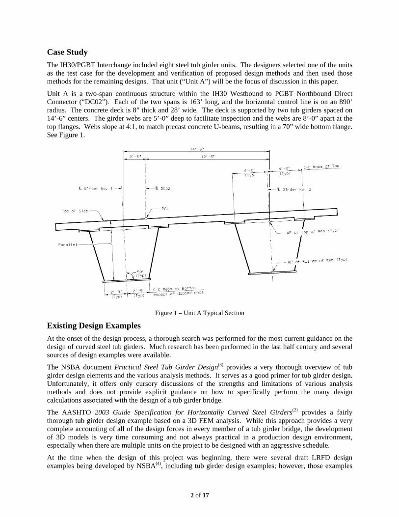
Unit A is a two-span continuous structure within the IH30 Westbound to PGBT Northbound Direct Connector (“DC02”). Each of the two spans is 163’ long, and the horizontal control line is on an 890’ radius. The concrete deck is 8” thick and 28’ wide. The deck is supported by two tub girders spaced on 14’-6” centers. The girder webs are 5’-0” deep to facilitate inspection and the webs are 8’-0” apart at the top flanges. Webs slope at 4:1, to match precast concrete U-beams, resulting in a 70” wide bottom flange. See Figure 1.
Figure 1 – Unit A Typical Section
Existing Design Examples
At the onset of the design process, a thorough search was performed for the most current guidance on the design of curved steel tub girders. Much research has been performed in the last half century and several sources of design examples were available.
The NSBA document Practical Steel Tub Girder Design(3) provides a very thorough overview of tub girder design elements and the various analysis methods. It serves as a good primer for tub girder design. Unfortunately, it offers only cursory discussions of the strengths and limitations of various analysis methods and does not provide explicit guidance on how to specifically perform the many design calculations associated with the design of a tub girder bridge.
The AASHTO 2003 Guide Specification for Horizontally Curved Steel Girders(2) provides a fairly thorough tub girder design example based on a 3D FEM analysis. While this approach provides a very complete accounting of all of the design forces in every member of a tub girder bridge, the development of 3D models is very time consuming and not always practical in a production design environment, especially when there are multiple units on the project to be designed with an aggressive schedule.
At the time when the design of this project was beginning, there were several draft LRFD design examples being developed by NSBA(4), including tub girder design examples; however, those examples
3 of 17
were also based on 3D FEM analyses and focused primarily on the changes in the girder design specifications associated with the use of the LRFD method.
Tub Girders vs. I-Girders
Prior to discussing the design methods for tub girders, it is important to explain some of the differences between tub girders and I-girders. Many designers have experience or knowledge of curved steel I-girder bridge behavior, but it is important to recognize the significant differences in the behavior of tub girders.
Much like an I-girder bridge, a tub girder bridge has a non-composite and a composite state for bending. But a tub girder bridge also has the same two states for torsion. Once the concrete deck is cast, tub girders become a truly closed shape and have torsional stiffness that is an order of magnitude stiffer than their I-girder counterparts. Prior to the deck hardening, tub girders rely on top flange lateral bracing to produce a pseudo-closed shape that is also significantly stiffer torsionally than an I-girder. Because of its increased torsional stiffness, the primary load path for torque resulting from horizontal curvature is through torsion in the girder itself. This is in contrast with I-girders that rely on external crossframes between multiple girders to resist torque on the system. This represents a fundamental difference in the behavior of I-girder and tub girder systems. I-girders resist loads associated with curvature primarily through overall system behavior, using discrete members that can be easily represented in a 2D analysis model. Tub girders resist loads associated with curvature primarily within the individual girders, each of which is a complex, multi-element structure, whose component parts cannot be directly represented in a 2D analysis model.
The higher torsional stiffness of tub girders results in a different distribution of load in the system compared to what occurs in an I-girder system. In an I-girder bridge there is more tendency for loads to shift toward girders on the outside of the curve, and designers will typically see that the outside girders require larger plate sizes than the interior girders. Since tub girders are torsionally stiffer and shed significantly less load to the girders on the outside of the curve, it is more common that the required flange and web dimensions in the various tub girders would be the same at a particular section along the unit.
Tub Girder Components
As we discuss the design methodology for the girders, we will highlight the various components that make up a steel tub girder. A complete girder system consists of:
• Girder Webs and Flanges cut from plate steel similar to I-girders.
• Internal Intermediate Diaphragms utilized to maintain the cross section geometry of the webs and flanges. Diaphragms typically consist of single angle members in a chevron configuration inside the tub section.
• External Intermediate Diaphragms between the girders are utilized to control the relative displacement and twist of the girders during slab placement. External diaphragms are not required once the slab has hardened and are often removed. Temporary diaphragms are typically single angle members similar to an I-girder crossframe, while diaphragms that are left in place are often full depth plate diaphragms.
• Pier and End Diaphragms are utilized at ends of units and at interior piers to resolve torque in the girders into bearing reactions at the pier caps. Pier diaphragms are typical solid plate webs and flanges; however, their design is complicated by the need to provide access holes in the webs for inspection access.
• Top Flange Lateral Bracing performs little function once the slab has hardened, but is critical for providing torsion stiffness prior to the slab hardening. Top lateral bracing typically consists of angle or WT sections in a truss configuration bolted directly to the top flanges of the girders.

4 of 17
Design Methodology
Girder Design
There are several commercially available bridge design software packages that can perform a 2D grid analysis of a curved tub girder bridge system. These programs typically incorporate some sort of user input forms with numerical and graphical output. A main benefit of utilizing these software packages is the ease and speed at which models can be created and analyzed. The programs can develop live load influence surfaces and provide output in minutes, as opposed to an hour or more, to generate the same output in a 3D FEA model. This increase in analysis speed provides the designer the opportunity to easily perform many design iterations and arrive at very efficient final designs. By running several iterations, the designer can also develop a better understanding of the behavior of the structure. The primary girder designs for the Unit A were performed utilizing the commercially available steel bridge design software package MDX. In addition to calculating moments, shears, and torques in the girders, MDX performs code checks on the girder flanges and webs and gives a good first cut on all of the plate sizes. Other proprietary programs perform similar checks.
As previously mentioned, the primary drawback of utilizing 2D grid analysis packages for tub girder designs is that they typically do not capture the full complexity of the torsional aspect of curved box girder design. On the IH30/PGBT Interchange, supplemental calculations were developed to design the miscellaneous components that were not adequately addressed by the primary design software.
Torsion During Slab Placement
The primary difference between an open section beam, such as an I-girder, and a closed section beam, such as a tub girder with top flange lateral bracing, is that the closed section carries the applied torques primarily via St. Venant torsional shear flow around the perimeter of the section. This results in additional shear stress in the webs and bottom flanges that must be accounted for in the design. This is particularly important for the design of the top flange lateral bracing, which effectively forms the “fourth side of the box,” creating a pseudo-closed section prior to the slab hardening.
When investigating the maximum torsion in the girder during slab placement, it is important to consider the slab placement sequence. Some DOTs may prefer a traditional placement sequence where the positive moment regions are placed and allowed to cure, followed by negative moment regions. Other DOTs may prefer to allow for a continuous placement from one end of the unit to the other. Regardless of the specified approach, it is physically impossible to instantaneously apply the weight of the wet slab to the entire unit at once, and thus an incremental slab placement analysis should be performed. Although MDX reports moments and shears taking into consideration a user defined slab placement sequence, at the time the subject project was under design, the software did not report torsion in the girder during the various slab placements. While the slab placement sequence typically has little effect on the sizing of girder webs and flanges, it has a significant effect on top flange lateral bracing forces.
To overcome this limitation, the designers had to find another method of calculating the torsion in the girders. Although the required analyses could have been performed using a 3D FEA approach, the designers chose to use the “M over R” method, or M/R, developed 40 years ago(5). The M/R method is similar to the V-Load method originally published by US Steel(6) for estimating curvature effects in I-girders and provides an accurate numerical method for calculating the torsion in horizontally curved closed section girders.
The M/R method accurately characterizes the torque in single closed sections, but it does not account for the effects of intermediate external diaphragms between girders in a multi-girder system. These external diaphragms provide shear transfer between adjacent girders, similar to how cross-frames in a curved I-girder system would, resulting in a slight reduction in the overall torque in the girders. Through parametric 3D FEA studies, this reduction was found to be on the order of 10%. For the purposes of

5 of 17
simplifying the calculation and the effects of incremental slab placement on girder torques, the participation of the external diaphragms was neglected in the M/R analyses.
The designers took the incremental moments from each slab placement as reported by MDX and calculated the corresponding torque for each slab placement using the M/R method. Because the torque in the girder is directly related to the vertical bending moment, the influence diagram for torque due to horizontal curvature is very similar to the bending moment and as would be expected, the maximum torque occurs during the placement of the first slab area.
Figure 2 – Unit A Slab Placement Sequence
Unit A was designed for three slab placements, the first span positive moment region, second span positive moment region, and then the negative moment region – Figure 2. Figure 3 shows the incremental torques for each individual slab placement and Figure 4 shows the cumulative torque in the girder following each placement.
Figure 3 – Incremental Torques from Each Placement

6 of 17
Figure 4 – Cumulative Torques after Each Placement
It can be seen that the maximum torque after the first placement is 270 k-ft, and the final toque after the third slab placement is 203 k-ft. Thus, the incremental analysis demonstrated that staged slab placement produces a 31% higher torque at the end of the girder, and will result in significant higher forces in both the top lateral braces and end diaphragms compared to instantaneous placement of the entire slab without consideration of the slab placement sequence.
Top Flange Lateral Bracing
Now that the maximum torque has been adequately captured, the torsion in the girder must be converted into a force in the top lateral bracing system. The top flange lateral bracing members not only carry forces due to torsion because of their location in the plane of the top flange, they also develop significant forces due to participation in the vertical bending of the girder. This interaction is not directly addressed in a 2D analysis, and while it would be adequately captured in a 3D FEA model, developing a full 3D model would require significantly more effort by the designer.
To provide a better estimate of top flange lateral bracing force without the use of a 3D model, Fan and Helwig(7) developed equations to determine brace forces based on the torque and vertical bending that can be derived from a grid analysis. The resultant force is a combination of brace force due to torque based on the shear flow in the closed section and the brace force due to vertical bending based on the vertical bending moment, brace stiffness, and brace orientation. The research also resulted in an expression quantifying the lateral bending stress induced in the flange due to the truss forces.
Armed with these equations, designers have the tools needed to fully characterize the forces in the top lateral bracing system with a full 3D FEA model. By isolating the forces due to torsion and vertical bending, designers can select the optimum brace orientation for the particular unit geometric configuration. As seen in Figure 4, the torque in the girders is highest at the end diaphragms; it is logical that a designer might choose to orient the braces so the maximum force in the brace at the end of the unit is in tension. However, when considering the vertical bending component of the brace force, the optimum brace orientation considering torsion alone may result in larger total brace forces. Figure 5 shows brace forces in Unit A.

7 of 17
.
Figure 5 – Unit A Top Flange Lateral Brace Forces – Warren Truss
The brace forces shown are for a Warren truss configuration where the torsion in the girder results in an alternating tension-compression pattern in the brace forces. So, although braces were oriented for tension at the end of the unit, the maximum brace force actually occurs at the second brace, and is a compressive force. Examining Figure 5, one can see that the vertical bending component of the truss forces trend toward brace forces in compression in the positive moment regions and tensile forces in the negative moment region.
There has been some discussion in the bridge engineering community and even a brief mention in the commentary of the AASTHO LRFD Bridge Design Specifications(8) about the advantages of using a Pratt truss configuration for the top flange lateral bracing. The potential advantages are two-fold: orientation of the braces in a manner that puts them primarily in tension allowing for smaller brace sizes, and elimination of the strut to flange connection that induces lateral bending moments into the flange (discussion to follow). Figure 6 shows a typical Warren Truss configuration, while Figure 7 illustrates a Pratt configuration. Under pure torsional loading of consistent sign, a Warren truss would result in alternating tension and compression, as seen in Figure 5, while a Pratt truss could theoretically be oriented to result in tension in every brace member.
Figure 6 – Typical Warren Truss(9) Figure 7 – Typical Pratt Truss(9)

8 of 17
The top flange lateral bracing, however, is not subject to solely torsional loading and the influence of the vertical bending moment will result in some braces experiencing compression forces. Furthermore, the simplest form of Pratt truss would orient the braces to produce tension in the braces at the end of the unit and then continue that pattern throughout the span. This configuration would result in the brace forces shown in Figure 8. It can be seen that although the brace forces do not alternate between tension and compression as they did in the Warren truss, there is still significant compression in the brace forces near the middle of each span. The basic Pratt truss does not address the reversal in the torque diagram of the girder and results in several braces where the compression due to vertical bending is additive to the compression due to the torque.
Figure 8 – Unit A Top Flange Lateral Brace Forces – Pratt Truss
A modified Pratt configuration that includes a change in the orientation of the braces near mid span could address the reversal in sign on the torque diagram and keep the torsional effect on the braces in tension. The tension due to torsion now offsets the compression due to vertical and the maximum compression force in the braces is significantly reduced – see Figure 9. This is an ideal truss configuration for minimizing compression in the diagonals and reducing the required size of the brace.
Figure 9 – Unit A Top Flange Lateral Brace Forces – Modified Pratt Truss

9 of 17
The primary drawback of utilizing the modified Pratt truss shown in combination with a 2D analysis approach is that the top flange lateral bending equations developed by Fan and Helwig are based on a Warren truss and not applicable to a Pratt configuration. A more detailed analysis would be required. In the case of Unit A, little would have been gained by going to a modified Pratt truss. The reduction in compression might have allowed for a slight reduction in the size and weight of the brace members, but the cost of these members is driven largely by the fabrication costs. The connection to the top flange becomes the critical price component and the controlling connection design force is independent of tension or compression, and the controlling force at the first brace is the same with all truss configurations. The goal on Unit A was to eliminate the need for gusset plates at the truss to flange connections, and that was accomplished without the need of a modified Pratt truss. Unit A utilized a Warren truss to simplify the calculations, but designers may find an advantage to utilizing a modified Pratt truss on other designs if the project schedule permits additional time in analysis.
Top Flange Lateral Bending
Curved I-girder bridges develop lateral flange bending moments in both the top and bottom flange due to warping of the girder cross-section. This lateral flange bending moment in I-girders is captured and reported by most analysis programs utilizing the V-LOAD formula(6). In steel tub girders, however, the lateral flange stresses due to warping of the cross section are negligible and are not reported by a grid analysis software package. Although there is little warping stress in the flanges due to girder torsion, there are other sources of significant contributors to lateral bending stress in the top flange that often go unaccounted for in 2D grid analysis programs. The designer should consider the effects of lateral flange bending due to the top lateral bracing truss, the shear on the inclined web, and lateral forces due to construction loads. The effect of the loads on the top flange can be significant, especially for relatively narrow flanges.
Depending on the orientation of the top lateral bracing truss, there are typically locations where either a strut member frames directly into the top flange with no intersecting diagonal, or where the difference in force between the strut and the diagonal is such that the top flange must provide the lateral reaction to statically resolve the forces. This lateral reaction of the top flange creates a bending moment in the flange. A helpful analogy is to consider the flange as a continuous beam, where each lateral bracing connection provides an elastic support for the load applied by the adjacent truss members. This is the basis of the Fan and Helwig expressions for flange lateral bending mentioned above. The resulting flange lateral bending stresses can be significant and should not be ignored.
As mentioned above, the Fan and Helwig equations are not applicable for a Pratt truss configuration. The continuous nature of the load path in a Pratt truss does not result in the same effective supports for the flanges as would be seen in the Warren truss, and a more detailed analysis would be required. It may be logical to conclude that since the Pratt truss does not include the condition of the strut framing into the flange without a restraining diagonal, that a Pratt truss does not experience lateral flange bending, but this conclusion would be incorrect. While a Pratt truss does not develop the same magnitude of lateral bending moment at every strut connection as a Warren truss, 3D analyses have shown that very large lateral bending moments are developed near the interior pier diaphragm where the lateral reaction is provided to the flange. A similar condition exists in a modified Pratt truss, as discussed above, where the orientation of the diagonal changes near mid span. Thus the use of a Pratt top flange lateral bracing system does not eliminate lateral flange bending moments.
Also addressed by Fan and Helwig is the lateral force on the flange resulting from applying a vertical force through an inclined web. The top flange lateral bracing again must provide a horizontal reaction to the system in order to resolve the forces. This results in flange lateral bending between the internal diaphragms and flange lateral bending stresses that should be considered.
Lastly, the slab construction methods should also be considered. Slab overhangs are typically formed utilizing brackets that connect to the top and bottom flange of the girder. The weight of the wet concrete

10 of 17
in the overhang and the load of the travelling slab screed represent eccentrically applied vertical loads, which result in lateral forces on the top flange. The tub girder design example presented in the AASHTO 2003 Guide Specification for Horizontally Curved Steel Girders(2) illustrates this scenario and suggests appropriate construction loads to consider.
These contributors to top flange lateral bending are typically not adequately addressed by 2D steel girder design software. The designer should consider these contributions to lateral bending moment independently, combine them with the vertical bending moments from the software, and perform the appropriate code checks to verify the performance ratios of the top flange.
Internal Diaphragm Design
Internal diaphragms are provided at regular spacing to control the cross-section geometry of the box and reduce any internal stresses due to distortion and warping of the cross section. Heinz(10) provided expressions for required spacing and size of brace members required to control warping stresses in box girders based on span and radius of curvature. These equations are a good place to start and have typically been found to be conservative(3). The actual spacing of internal diaphragms is coordinated with the spacing of the top flange lateral bracing system, with internal diaphragms typically spaced at every, or every other, lateral brace panel point. The top strut of the internal diaphragm participates in the top flange lateral bracing system and should be designed for the calculated forces. Other members in the internal diaphragm see low forces and are sized as secondary members. The University of Texas has recently published guidance on quantifying the forces in internal diaphragms in the Center for Transportation Research Report CTR 0-4307(11).
Intermediate External Diaphragm Design
External diaphragms are sometimes required to control the relative twist of the girders during slab placement to avoid problems with achieving uniform slab thickness, and occasionally to ensure global stability of the individual box girders. Report CTR 0-4307(11) presents equations for determining maximum diaphragm spacing and anticipated forces based twist compatibility between the two girders. Most 2D analysis software allows designers to include external intermediate diaphragms and provides shears and moments in the diaphragm. However, designers are cautioned that often these diaphragms are modeled as extending between the centerlines of adjacent girders, and the shears and moments reported at the centerline of the girders. As a result, the model results may not accurately reflect the actual stiffness of, or forces developed in, the diaphragms.
Historically the external diaphragms have been treated as temporary and were removed in the final structure; however, there has been a desire by some DOTs in recent years to leave the diaphragms in place. There are several reasons for this. Primarily, it is often not worth the cost of removing them; the completed girders may be located over live traffic and the consequences of closing lanes just to remove braces are not appealing to owners. Secondly, the diaphragms would need to be reinstalled at a later date to facilitate any future re-decking operations. If it is decided to leave the diaphragms in place, it is necessary to consider fatigue in the connection details. Fatigue considerations will often drive the design toward full or partial depth plate diaphragms with bolted connections rather than welded k-frames. Unit A utilized full depth stay-in-place diaphragms with bolted connections – see Figure 10.

11 of 17
Figure 10 – Unit A Intermediate External Diaphragm
The external diaphragms were modeled in the analysis of Unit A as full depth diaphragms between the girder centerlines. The bolted connections were sized for the dead and live load moments and shears reported from the analysis software. The resulting bolted connection, in turn, drove the required depth of the diaphragm and the analysis was rerun with the stiffer diaphragm; iterations proceeded to convergence. The resulting design was checked against the CTR 0-4307(11) recommendations and found to adequately control the twist of the girders during slab placement.
The University of Texas recently developed a tool that could help future designers more accurately size external diaphragms(12). The software, UTrAp, was developed as an easy-to-use 3D FEA package that models units with multiple tub girders and reports the force of all internal members, including top flange lateral bracing, internal diaphragms, and external diaphragms. At the time of the design of Unit A, the software did not model full depth diaphragms, but designers should consider the software for future designs.
Pier Diaphragm Design
A pier diaphragm in a tub girder unit typically consists of a full-depth plate structure that transversely ties the girders together and resolves torsions and shears in the girders into reactions to the substructure. As discussed previously, most software packages will analyze and perform code checks for pier diaphragms. However, with the limited input and output in the 2D software, it is difficult to verify the design assumptions. It is prudent to perform the design of the diaphragms outside the 2D analysis program.
The first step in designing diaphragms at supports is to analyze the shears and torque in the girders at the support and solve for the reactions below each girder using an analysis of shear flow through the girder section– Figure 11.

12 of 17
Figure 11 – Resolution of Forces by Statics
Next, the designer must convert the torsion in the girder into a shear flow and distribute that shear flow around the perimeter of the girder – Figure 12.
Figure 12 – Distribution of Torsional Shear Flow
With the reactions determined, and the shears in the webs and flanges known, a shear and moment diagram for the diaphragm can be easily developed – Figures 13 and 14.
Figure 13 – End Diaphragm Shear Diagram
13 of 17
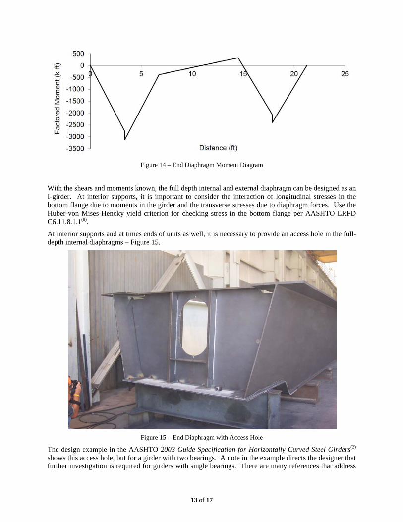
Figure 14 – End Diaphragm Moment Diagram
With the shears and moments known, the full depth internal and external diaphragm can be designed as an I-girder. At interior supports, it is important to consider the interaction of longitudinal stresses in the bottom flange due to moments in the girder and the transverse stresses due to diaphragm forces. Use the Huber-von Mises-Hencky yield criterion for checking stress in the bottom flange per AASHTO LRFD C6.11.8.1.1(8).
At interior supports and at times ends of units as well, it is necessary to provide an access hole in the full-depth internal diaphragms – Figure 15.
Figure 15 – End Diaphragm with Access Hole
The design example in the AASHTO 2003 Guide Specification for Horizontally Curved Steel Girders(2) shows this access hole, but for a girder with two bearings. A note in the example directs the designer that further investigation is required for girders with single bearings. There are many references that address

14 of 17
holes in the webs of steel girders, but most present the problem in regions of constant shear in the girder. They do not address what is happening when the hole is directly over the bearing device, which is common in tub girders with single bearings, leaving designers to their own resources to determine what the actual forces are in the web between the bearing stiffeners. An investigation of this condition can be accomplished by analyzing the diaphragm under two separate conditions: a global analysis, similar to what would be done with no hole, and a local analysis of the portion of diaphragm between the bearing stiffeners.
The global analysis is similar to that presented above, but assumes the total reaction at each bearing is distributed equally to the two bearing stiffeners, resulting in effectively zero shear between the stiffeners. The bending moment in the girder is then conservatively taken as the moment assuming a single bearing point. The stresses due to bending at the centerline of bearing can be determined by examining the diaphragm section with the hole removed, Figure 16.
Figure 16 – Diaphragm Cross-Section with Access Hole
By assuming that the total reaction at the bearing is being carried by the stiffeners, a local analysis must be performed that considers the bending of the diaphragms between the stiffeners. The bearing device has a known dimension and it is assumed that it applies a uniform pressure to the bottom flange of the girder, Figure 17.
Figure 17 – Loading from Bearing Device

15 of 17
A shear and moment diagram for the diaphragm within the limits of the bearing device can easily be determined. The local shear and moment is resisted entirely by the portion of the diaphragm below the access hole only; the upper portion of the diaphragm is considered ineffective for this local analysis, Figures 18 and 19.
Figure 18 – Diaphragm Shear Below Access Hole Figure 19 – Diaphragm Moment Below Access Hole
Bending stresses and shears from the global and local analyses are then superpositioned to determine the net stress in the lower portion of the diaphragm, Figure 20.
Figure 20 – Superimposed Stresses in Diaphragm
In this scenario, the portion of the diaphragm in consideration is a T section. AASHTO gives limits for outstanding legs of angles and tees. In order to develop the required capacity, it is often necessary to consider an effective depth beyond these limits. Therefore, in order to brace the outstanding leg of the T section, an additional horizontal plate must be placed just below the access hole, as can be seen in Figure 15. This effectively creates a singly-symmetric section for checking the bending and shear stresses.
Conclusions Trapezoidal box girders provide an attractive, torsionally stiff solution for bridge spans with tight curvature. While some aspects of tub girder design are similar to I-girders, the torsional behavior of the closed section is unique and must be addressed in the design. Commercially available 2D analysis software packages typically provide an adequate model of the girders in their final condition with the slab hardened, but the design of these girders is complicated by numerous internal framing elements that perform critical functions in the non-composite condition. It is imperative that designers verify the adequacy of not only the girders, but also the various internal framing elements, during slab placement. The critical elements to consider during slab placement include the top flange lateral bracing and the

16 of 17
internal and external diaphragms. Designers are encouraged to utilize the hand methods presented here or utilize simple FEA models or available software, such as UTrAp(12) .
The expanding capabilities of commercial 2D analysis software has provided a viable option for the design of tub girders and reduced the need for full 3D models. As with all “black box” software programs, it is imperative that designers fully understand the capabilities and limitations of the tool. As the available software improves and more features are added, it will continue to be the designer’s responsibility to ensure the completeness of the design and to challenge the results of the analysis software. The methods presented in this paper provide designers with the tools to verify analysis results resulting in an increased comfort level with utilizing 2D grid analysis for the design of trapezoidal box girders.

17 of 17
References
(1) American Association of State Highway Transportation Officials (AASHTO), Standard Specification for the Design of Highway Bridges, 17th Edition, HB-17, 2002
(2) American Association of State Highway Transportation Officials (AASHTO), Guide Specifications for Horizontally Curved Steel Girder Highway Bridges, GHC-4, 2003.
(3) Coletti, D., Fan, Z., Gatti, W., Holt, J., and Vogel, J., ”Practical Steel Tub Girder Design,” National Steel Bridge Alliance (NSBA), April 2005
(4) HDR Engineering, “Example 4: Three Span Continuous Composite Box Girder,” Steel Bridge Design Manual, National Steel Bridge Alliance (NSBA) and Federal Highway Administration (FHWA), DRAFT 2003
(5) Tung, D.H.H, and Fountain, R.S., “Approximate Torsional Analysis of Curved Box Girders by the M/R Method,” AISC Engineering Journal, Vol. 7, No. 3, July 1970.
(6) Richardson, Gordon & Associates, Consulting Engineers, “Analysis and Design of Horizontally Curved Steel Bridge Girders,” United States Steel Structural Report, 1963
(7) Fan, Z., and Helwig, T., “Behavior of Steel Box Girders with Top Flange Bracing,” ASCE Journal of Structural Engineering, Vol. 125, No. 8, August, 1999, pp 829-837.
(8) American Association of State Highway Transportation Officials (AASHTO), LRFD Bridge Design Specification, 5th Edition, 2010
(9) From AASHTO/NSBA Collaboration Document G1.4 “Guidelines for Design Details,” 2006
(10) Heinz, C.P., “Box Girder Bridge Design – State of the Art,” AISC Engineering Journal, 4th quarter, 1978
(11) Helwig, T., Yura, J., Herman, R., Williamson, E. and Li, D., “Design Guidelines for Steel Trapezoidal Box Girder Systems,” CTR 0-4307, Center for Transportation Research at the University of Texas at Austin, April 2007.
(12) Topkaya, C., Yura, J., Williamson, E., Frank, K., “UTrAP: Finite-Element-Based Software for the Analysis of Curved Trapezoidal Girders under Construction Loads,” CTR 0-1898, Center for Transportation Research at the University of Texas at Austin, October 2002.