cupcake cnc batch 10+ & starter kit build...
TRANSCRIPT

Cupcake CNC Batch 10+ & Starter Kit Build Instructions
Ordinarily, it will take a couple of people a weekend or so to put a Cupcake CNC together. Here's how!Before you begin you might want to check out this collection of videos tutorial detailing every step of the build process(deluxe kit). Please note these videos are done with a PRE BATCH 10 deluxe kit. The optical end stops are no longerincluded. There may also be some other differences.
Additionally, for those who are assembling an Ultimate kit or are otherwise creating several of our new upgrade kits atonce: we strongly recommend that you step through them one at a time. Build your Plastruder MK5 and print on theacrylic build platform before building your Automated Build Platform or Heated Build Platform. Your understanding of howthe interconnected elements of your bot function will increase and your build will proceed more smoothly.
Prep Work
Cupcake Parts List1.Before you begin2.About bolts and nuts3.About timing belts4.Some mistakes to avoid5.
Build It
Cupcake Y Stage Assembly1.Cupcake X Stage Assembly2.Cupcake Body Assembly3.Cupcake Z Stage Assembly4.Cupcake XY Stage Installation5.Cupcake Z Stage Installation6.
Finish It Up
Plastruder MK4 Build Instructions1.Cupcake Electronics Installation2.Cupcake Calibration3.Optional step: Cupcake Endstop Installation4.
Updating Your Firmware
Cupcake Motherboard Firmware Update1.Plastruder Firmware Update2.
ExperimentalHeated build platforms
Troubleshooting
When things go wrong!1.Think you are missing parts?2.
1 of 1 10/26/2012 12:21 AM

CupCake CNChttp://www.thingiverse.com/thing:457Part List: tree | flat | csv
Part Qty
Cupcake CNC Lasercut Parts Kit 1
Drive Rod Kit 1
X Rods 2
Y Rods 2
Z Rods 4
Stepper Motor NEMA17 200 3
Hardware Burrito 1
Hardware Burrito - M8 Hardware 1
M8 x 50mm socket cap bolt 3
M8 nut 30
M8 washer 15
Hardware Burrito - M5 Hardware 1
M5 x 45mm socket cap bolt 1
M5 nut 3
M5 washer 4
Hardware Burrito - M3 Hardware 1
M3 x 8mm socket cap bolt 16
M3 x 16mm socket cap bolt 200
M3 nut 200
Hardware Burrito - Misc Hardware 1
6-32 x 3/8" screws 4
M3 Spacer - 1/4" Length 25
3mm Cube Magnet 10
Hardware Burrito - Hex Keys 1
1.3mm hex key 1
1.5mm hex key 1
2.0mm hex key 1
2.5mm hex key 1
4.0mm hex key 1
6.0mm hex key 1
Belt & Pulleys Kit 1
Large Idler Pulley 3
X Belt 1
Y Belt 1
Z Belt 1
XY Motor Pulley 2
Z Rod Pulley 4
Z Motor Pulley 1
XY Linear Bearings 8
10/26/2012 1:18 AM

Generated by Thingiverse © 2012
Supplemental Bearing and Pulley Kit 1
608 Bearing 8
Small Idler Pulley 1
Modified lasercut X front 1
Modified lasercut X end cap 1
Generation 3 Electronics 1
Stepper Motor Driver v2.3 Fully Assembled 3
RepRap Motherboard v1.2 Fully Assembled 1
Extruder Controller v2.2 Fully Assembled 1
ABS Natural - 1lb coil 1
Plastruder MK4 1
Deluxe Add-ons Kit 1
Build Surface Kit 1
Acrylic Build Surface 1
Wooden Build Platform 1
3mm Cube Magnet 5
M3 x 10mm socket cap bolt 6
M3 nut 6
Tools Kit 1
13mm Wrench 2
1GB SD Card 1
Cables Kit 1
USB to TTL Cable 1
Power Cable - 6ft 1
Cat5e Cable - 2ft 1
ATX Power Supply 1
ABS Black - 5lb coil 1
10/26/2012 1:18 AM

The diagram below describes what we mean when we refer to, for example, the "left" or"bottom" of the machine:
The Cupcake CNC moves pieces and tools along three axis: the X axis, the Y axis, and the Zaxis. The X axis is the one that runs from left to right; the Y axis is the one that runs towardsand away from you. (Think of these as being like the X and Y axis of a graph, seen fromabove.) The Z axis goes up and down.
Spend a moment to study this illustration carefully— it seems simple, but it will save you a lotof time and frustration later!
There are some common tools and supplies that are required to build the Cupcake CNC butdon't ship with the deluxe kit:
10/26/2012 12:27 AM

Soldering ironYou'll need to make four easy solder connections to hook up the Plastruder Mk4
1.
Electronics solder2.Pliers, preferably needle-nosed
These will help you tighten down nuts3.
Hot glue gunA dab of hot glue will help keep the bearings from coming loose
4.
Super glue, or white glueA bit of glue can be used to make sure the magnets don't come loose from theirpress-fit bearings
5.
You may also want these additional items, which are suggested in the Z Stage Assemblyinstructions:
Loctite thread locking compound1.Bikechain lubricant or some other such compound2.
10/26/2012 12:27 AM

Cupcake CNC uses metric hardware for all its fasteners. Metric bolts are described in terms ofthe diameter of their shafts. For instance, an "M3" bolt is one with a shaft that is 3mm indiameter. Likewise, an M8 bolt has an 8mm shaft diameter. M3 nuts are nuts that fit M3 bolts.
The Cupcake CNC uses bolts of several lengths. They're described by the length of the boltexcluding the head. For example, a 16mm bolt is 16mm from the tip of the screw to theunderside of the head. Sometimes you'll see a bolt described, for example, as M3x16. Thatmeans an M3 bolt with a length of 16mm, excluding the head.
Almost every one of the nuts and bolts you'll use will be M3x16 - the Cupcake comes with 180M3x16 nuts and bolts, but you'll end up with quite a few left over.
Nuts and bolts holdthe MakerBot together.You put the nut in thet-slot, put the bolt inthe hole and twist itwith your fingers.Once you've got ithand tight, give it asmall twist with theallen key to make sureit stays tight.
The Cupcake CNCuses two lengths ofM3 bolt. The 16mmbolts are used to holdthe wooden partstogether; the 10mmM3 bolts are used tofasten the NEMA 17stepper motors to thebot. Be sure not touse the 16mm bolts toattach the motors— they can enter the motor housings and cause them to jam!
M3 nuts are not manufactured to very tight specs, so some may be slightly smaller or largerthan others. Additionally, wood always has a little variability. If you're having trouble fitting a nutinto a t-slot, try rotating the nut a sixth of a turn, or inserting the nut from the other side of thet-slot and see if you have an easier time of it. If you're really stuck, try lightly sanding or filingthe slot.
1 of 2 10/26/2012 12:30 AM

Sometimes the t-slot is actually a touch too wide, and won't hold the bolt in place until you'reready to screw in the bolt. In these cases, you can add a dot of white glue or super glue tokeep it from falling out until you're ready to screw in the corresponding bolt.
MakerBots vibrate, so you're going to want to occasionally check the nuts and bolts andtighten them down if they loosen up. Most bolts, like those in the outer frame, may never needtightening; others, like those that hold the build platform down, may need to be checked everyfew months or so.
The slots and tabs inthe frame shouldmatch up well. Ifyou've screwed acouple of partstogether, and arehaving trouble fittingthe tabs on a thirdpart that connects toboth, try loosening thebolts first.
2 of 2 10/26/2012 12:30 AM

Cupcake CNC uses timing belts to move its various parts. Timing belts are belts made ofreinforced rubber with little teeth molded onto the inside, which mesh with slots in pulleys.Cupcake CNC uses continuous belts 6mm in width, with 2mm between teeth (the GT2 drivesystem).
The belts we use have silkscreened part numbers which include the number of teeth on thebelt. For example, this belt has the code: GATES GT 2MR193 2655MC
The number after the "R" indicates the number of teeth on the belt. In this example, forinstance, the belt has 193 teeth.
We mount our idler pulleys in slots to allow you to tension the belt properly, but even when thepulleys are at their loosest, it can be tough to get the belt around them. Often, it is simplest torun the belt around all the pulleys except for the small metal drive pulley first. Then get thebelt partway around the drive pulley, and then rotate the pulley to pull the belt onto it.
In general, belts should be tight enough to minimize slack, but not so tight that they startplacing a lot of stress on the motor shaft or pulleys. Once a belt is on, turn the motor pulleywith your fingers to gauge if there's too much resistance. In general the belts should not betight enough to make a distinct note when plucked with your finger. Also, if your motor makes ahumming or buzzing noise when operating, loosen the belts, operation should be nearly silent.
The three belts need to be tensioned in slightly different ways:
Y belt: the Y belt needs to be relatively tight to make sure that the idler pulley boltdoesn't collide with the X rods. See the [cupcake-cnc-10:cupcake-x-stage-assembly Xstage assembly instructions] for details.X belt: the X belt should be reasonably tight, without being so tight that it offers a lot ofresistance.

Z belt: the Z belt should be relatively slack; it doesn't need to be as tight as the other twobelts, and overtightening can cause the Z stage to sometimes miss steps.
Before you get started, you may want to review Don't Do That!
2 of 2 10/26/2012 12:32 AM

OH NO CUPCAKES!
Several MakerBot builders have shared their mistakes and missteps in the hopes that otherswill not follow in their footsteps! Everyone makes some mistakes putting their machinestogether, and yet they all eventually work. Hopefully this section will both provide usefulinformation and make you feel better when you make your own errors. The names have beenremoved to protect the embarrassed!. We will add to this list based on what comes through theMakerBot Operators group, but feel free to add your own experiences by editing the page.
Be sure and also check out the "When things go wrong" page at: When things go wrong!
Be careful when you cut down your threaded rods!
Heh- just a warning for those of you working on your Makerbots- bevery careful if/when you cut down the M8 threaded rod of the Z-stage.I inadvertently cut it too short, and had to reorder another set ofrods from McMaster-Carr. My suggestion is to get the whole thing
10/26/2012 12:33 AM

working, and then cut them down at that point. I thought I was beingclever by doing it at the beginning, but I made an error ofmeasurement rather than working from an assembled Makerbot. Lessonlearned, but hopefully nobody else is this dumb… :-)
I would like to add, if you are cutting your own M8 rods with a dremel or > othercutting device, not to grab the end you cut with bare fingers just > after cutting,i now have a nice M8 thread branded into my fingers for the > next week orso… From Roboteernat.
Double-check that the sides are on the right ways!
HA HA HA! At least you didnt assemble your whole makerbot to figure out thatyour sides were backwards
If you always remember that the labels face _outward_ and watch the illustrations on the buildinstructions carefully, you should be okay.
Switch your power supply to the right voltage!
I almost plugged in my MakerBot without switching the power supplyfrom 110V to 230V! Luckily I *accidently* glanced the 110/230V switchnext to the main power switch when pluging in the power cable.That was really close, I can tell you…
So I'd like to extend your warning for all new MakerBot operators inEurope: Remember to switch the power supply to your actual current! :)
Make sure your idler wheel is well attached
Heh. Never use superglue to attach the idler wheel, mine fell off.Used Epoxy instead. Mucho strengtho!
If you must use superglue, get the good stuff, a reputable hobby shop will usually have glue ofthe right strength and viscosity.
Be very careful with the small SMD parts!
Apart from loosing an SMD Capacitor and a resistor mine went quitesmooth… .
Don't forget to tighten the bolts on the plastruder motor!
10/26/2012 12:33 AM

how about disassembling your plastruder then reassembling thendisassembling because you forgot to tighten the bolts on the motor?
Make sure your laser cutter is in alignment!If you laser cut your own panels, make sure that the cutter is aligned before you start- theparts need a significant amount of precision to assemble and run properly.
At least you didn't assemble your makerbot z-body and then spend 30minutes figuring out that it didn't sit level because your lasercutter was out of alignment….
Be careful where you plug in your cables!
I had a long close look at the "not ethernet" ports on the MoBo,before I figured that the end stops probably do not plug into there..ha ha.. not sure what would have happened, but I know they feed powerfor the extruder sooo.
Don't unplug a stepper motor while its stepped board is powered!
I lost a stepper board this way trying to move the cable around.There's a warning on the cupcake-calibration pagebut I saw it too late.
Make sure you turn your motherboard on before you try to upload!
When you start the upload, you have to hit the reset button on themotherboard to get it to upload correctly. Yes, your motherboard shouldhave lights on it. If it does not, check the power switch. There should bea green power light at the very minimum near the top right under where youplug the TTL cable in. the LED underneath this should flash red while youare uploading.
Make sure your reset button is in alignment!When soldering in your reset button(s), make sure pin one on the switch lines up with pin oneon the board. If you put in sideways, the board is always resetting, meaning it'll never takefirmware.
Those four-pin reset switches? Directional. Don't just solder them inany-which-way; turn them over and look for the logo. The terminal to theright-side of the logo is generally pin 1. There's a notation on the
10/26/2012 12:33 AM

silkscreen for a reason
Make sure you thread the right end of the heater barrel into the insulatorThread the dressed/tapered end into the teflon or the gap will cause a dam to form that willforce the head apart.
Don't over-tighten the idler wheel!If you bought the MK4 UPGRADE kit for your MK3 be sure not to over-tighten the idler wheel itputs a ton of stress on the wheel and can fracture and/or break it!
"This is to all of you that bought the mk4 upgrade kit! dont tightenthe idler wheel down onto the metal rod that came with the kit! thisputs excess stress on the wheel and can cause it to crack and break…"
Don't over-tighten… period!!Be careful not to over-tighten the ubiquitous M3 16mm bolts. You can crack the pieces,especially the acrylic Plastruder pieces. Doh!
Don't lose the thermistor!It would be a good idea to make sure you never drop the thermistor, if you do it will most likelyvanish into thin air. Finding a needle in a haystack is trivial compared to finding a thermistorthe size of a hair in carpet. Just don't do it. Attaching a piece of tape to it until the wires aresoldered on would be a great idea too.
The 100k glass bead thermistors stick to magnets - so attaching it to a magnet is a good waynot to lose it! If you do drop it, a magnet can help you find it…
Don't get too carried away trying to unblock your extruder!That last bit of resistance I felt apparently wasn't solidified ABS residue after all…
10/26/2012 12:33 AM

Don't get too close while watching the print!I did and got my hair caught in the z-pulley and belt. Ouch!
If you change filament on the fly, make sure BOTH ends are nice & squareIf you're printing along and are thinking about swapping the filament - maybe you want tochange colors or are running out of filament - without stopping the print, make sure that bothends have nice, straight cuts to the end.
If you don't do this and one/both ends are wedge-shaped, the two filaments may try to workthemselves around each other. This is bad and can rapidly lead to you needing to rebuild thehot end. Straight, square cuts only!
Don't break your thermistor!!!Ever since I first built extruders, I have broken the thermistor that came with the extruder. Formy first 2 extruders, I had to order new thermistors. My MK5 is the only extruder I have notbroken the thermistor for.
Never overtighten anything!My first Cupcake has way overtightened bolts everywhere. Only tighten the T-slot connectors
10/26/2012 12:33 AM

to where the nut becomes snug but doesn't start digging into any wood. In the tough-to-reachplaces, you can make it dig a little so you don't have to go in and tighten them, but otherwisedon't overtighten.
Especially on the pulleys! DO NOT TIGHTEN DOWN THE PULLEY BOLTS UNTIL YOU HAVEUSED YOUR MACHINE QUITE A BIT AND KNOW THE OPTIMAL TENSION. I accidentallysmooshed the wood and now I am stuck with certain belt tensions. Fortunately they are okay :)
10/26/2012 12:33 AM

Table of Contents
SummaryParts listAssembly
Insert magnetsHow to install a magnet
Attach the acrylic stage to the Build PlatformClamp the Y belt to the Y ribAssemble the carriageInstall the flanged bearings
Building the Y stage should take you about thirty minutes.
These are the parts you'll need to assemble the Y stage. All laser-cut parts should have theirnames etched into them. Find and put aside these parts:
Laser-cut stage partsBuild platform
1 of 15 10/26/2012 12:36 AM

Y stageY frontY backY ribY clampAcrylic build surface
12 M3x16 bolts12 M3 nuts10 3mmx3mmx3mm gold magnets4 flanged slide bearings196 tooth continuous timing belt
You'll find the bolts in the bag labeled Hardware burrito.The lasercut parts are in the Cupcake CNC Lasercut Parts box.The belts and flanged bearings are in the Belt, Bearing and Pulley bag.
You'll also want to have on hand:
2 smooth Y rods (the shorter pair of rods)supergluehot glue gun or regular wood glue
If you have a deluxe kit, you'll probably also have a spare build surface kit, with an extra buildplatform and magnets. You can use these to build a spare platform, in case the one thatcomes in the laser-cut kit gets misplaced or damaged. Just make sure that you get themagnets the right way around when you do!
The small square magnets keep the build platform firmly in place on the Y stage when theCupcake CNC is in motion. The magnets are press-fit into the square holes on the buildplatform.
All the magnets must be aligned in the same direction. The easiest way to make sure you don'tget a magnet backward is to stack them all so that they stick together.
2 of 15 10/26/2012 12:36 AM

Put a nut or other iron object at one end of the stack to make sure you don't get the stack
flipped around. Push the end of the stack without the nut into the hole until the magnet at the end of the stackis partway into the hole. If you're having trouble getting the magnet into the hole, try reamingout the edge of the hole slightly with a small tool, like a hex key. Once the magnet is in thehole should then be able to remove the rest of the stack.
3 of 15 10/26/2012 12:36 AM

Use a some sort of blunt tool to press the magnet the rest of the way into the hole. We like touse a large hex key for this. Don't hammer the magnets into the holes— you may shatter themagnets or the piece. If you're having a really hard time, try using a vise or clamp.
Place the Build platform and Y stage pieces on a flat work surface so that the text on
4 of 15 10/26/2012 12:36 AM

each piece is facing upwards.
Press five magnets into each of the square holes on the Build platform.
Use a small tool to push the magnets all the way to bottom of their holes. These magnetsshould be flush with the bottom of the Build platform. If they stick out from the bottom,push them back up a bit. Make sure they're not protruding— you need the bottom of theBuild platform to be flat against the top of the Y stage.
5 of 15 10/26/2012 12:36 AM

Add a dot of superglue to each hole to help lock each magnet in place. (You may want toglue in the holes on the back side. This will still hold the magnets in place and you willbe able to keep the front side with the flush magnets nice and smooth.)Press five magnets into each of the square holes on the Y stage.Make sure the magnets on the Y stage are flush with the top of the Y stage. If they stickup at all, push them down a little.
6 of 15 10/26/2012 12:36 AM

Add a dot of superglue to each hole to help lock each magnet in place.
..
10/26/2012 12:36 AM

Place the Build platform on top of the Y stage so that the round holes line up. Themagnets should each attract the corresponding magnet below it. If there are magnetsthat repel one another, you have a magnet in backwards— carefully push it out andinsert it the other way.Make sure the build surface and Y stage are flat against each other— if a magnet issticking up, it can be a pain to adjust for later.
..

Use 6 M3x16 bolts and 6 M3 nuts to attach the acrylic stage to the top of the Build Platform.
Put the Y belt (the small, 196 tooth one) on the Y rib so that the teeth of the belt meshwith the slots in the rib.
9 of 15 10/26/2012 12:36 AM

Use an M3x16 bolt and an M3 nut to attach the Y clamp to the Y rib.
Tighten the bolt with a hex key to firmly clamp the belt into place.
10 of 15 10/26/2012 12:36 AM

Insert M3 nuts into the captive nut slots on the Y rib, Y front and Y back pieces.
Assemble the Y rib, Y front and Y back pieces. Make sure the Y rib is facing towards thesmall slots in the Y front and Y back, and that the Y belt is threaded through these slotsas shown above.
.
10/26/2012 12:36 AM

Bolt the front and back on to the rib by hand. Don't tighten these bolts yet.
Slot the Y stage on to the rest of the assembly, and bolt it on with three screws.
.
10/26/2012 12:36 AM
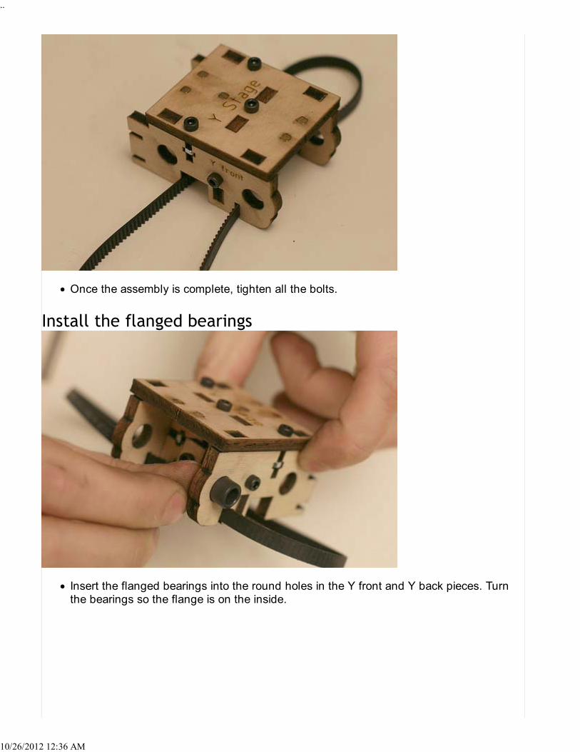
Once the assembly is complete, tighten all the bolts.
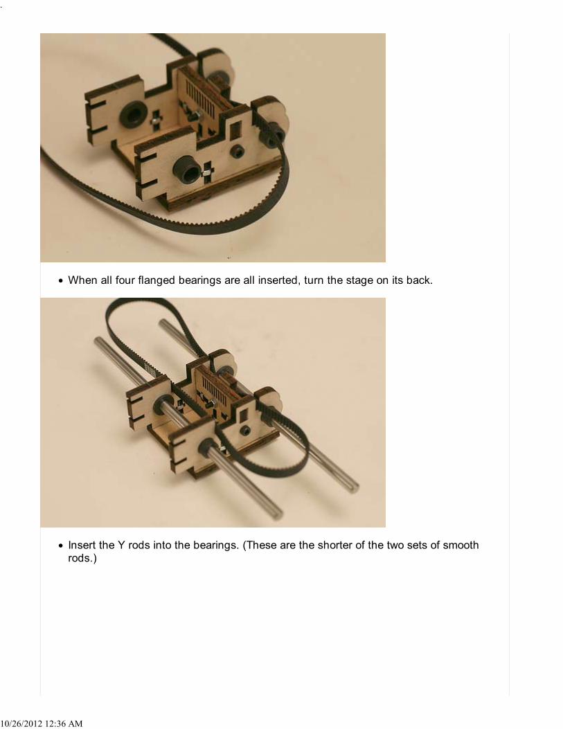
Insert the flanged bearings into the round holes in the Y front and Y back pieces. Turnthe bearings so the flange is on the inside.
..
10/26/2012 12:36 AM
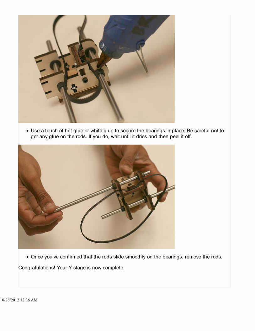
When all four flanged bearings are all inserted, turn the stage on its back.
Insert the Y rods into the bearings. (These are the shorter of the two sets of smoothrods.)
.
10/26/2012 12:36 AM
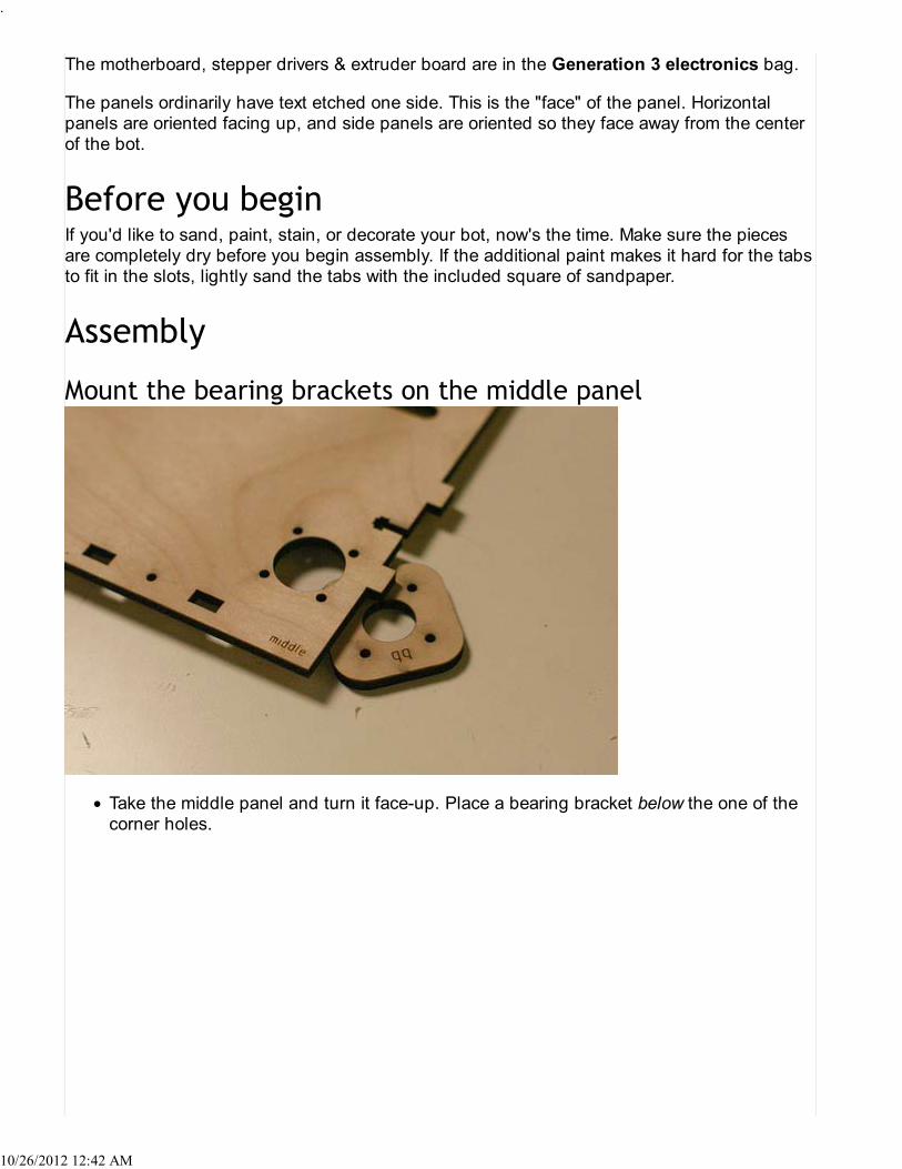
Use a touch of hot glue or white glue to secure the bearings in place. Be careful not toget any glue on the rods. If you do, wait until it dries and then peel it off.
Once you've confirmed that the rods slide smoothly on the bearings, remove the rods.
Congratulations! Your Y stage is now complete.
.
10/26/2012 12:36 AM

Building the X stage will take you about one and a half hours. You will need your previouslyassembled Y stage.
Take Note: the X front and front cap parts have changed as of the Batch 10 version ofthe kit! In your box, you may find two X front and X cap parts. They should be inside thebag marked "Supplemental Bearing and Pulley Kit". Use the new ones indicated in thepicture above! You can keep the old ones as souvenirs.
Take Note 2: There is a minor defect in CupCakes with a Serial Number of 982 andabove. This includes part of Batch #13 and all of Batch #14. Batch #15 should beunaffected. Check the M3 bolt holes on the X back part relative to an X cap part anddecide how you wish to proceed.
Take Note 3: The narrow slots that allow the timing belt to run through on X left and Xright are misaligned in batch 16. You will need to widen these slots slightly.
PICTURE NEEDED
Identify the small idler pulley to distinguish it from the Z stepper pulley. You'll find thesmall idler pulley in the Supplemental Bearing and Pulley Kit.
1 of 15 10/26/2012 12:39 AM

Laser-cut stage partsX stageX leftX rightX frontX backX ribX back capX front cap2 X clamps
NEMA 17 stepper motor17-tooth aluminum drive pulleySmall idler pulley (see above)1 M5 45mm bolt (not shown above)2 M5 nuts (not shown above)1 M5 washer (not shown above)4 flanged slide bearings23 M3 16mm bolts23 M3 nuts4 M3 10mm bolts2 smooth supporting X rods2 smooth supporting Y rods (not shown above)264 tooth continuous timing belt (the second-shortest one)
The lasercut parts are in the Cupcake CNC Lasercut Parts box.The M3 & M5 bolts, washers and nuts are in the Hardware burrito bag.The pulleys, belts, and flanged bearings are in the Belt, Bearing and Pulley bag.The rods are bagged in the Drive Rod Kit.The NEMA 17 motor is bubble-wrapped with the other NEMA 17 motors.
.
10/26/2012 12:39 AM

Attach each X clamp to the front of the X rib through the uppermost holes with a 16mmM3. Loosely thread a nut onto each bolt, but do not tighten. Rotate the two clamps sothey do not cover the slots in the rib.
Place the belt against the front of the rib so that the teeth of the rib engage the slots inthe rib. Swing the clamps over the belt.
.
10/26/2012 12:39 AM

Insert bolts in the lower set of holes and tighten all the nuts until the belt is firmlyclamped to the X rib.
Place 3 M3 nuts in the lower three T-slots on the X right and X left pieces. (You can leavethe two t-slots at the ends empty for now.)
4 of 15 10/26/2012 12:39 AM

Slot the X left and X right pieces into the X stage. The text on all three pieces should faceoutwards. Use six M3 bolts to tighten the sides to the stage.
Using the small hex key, loosen the set screws on the small aluminum pulley. Look downthe bore to make sure the set screws are completely out of the way.Push the pulley onto the motor shaft, set-screw end first. The fit is very tight; if you'rehaving a lot of trouble, try lightly sanding the inside of the pulley slightly. Adjust height ofpulley depending on the height of the small idler pulley. This height should be around 3millimeters.
5 of 15 10/26/2012 12:39 AM

Tighten both set screws with the hex key. Make sure they're nice and tight.
Place the motor inside the stage, with the wires facing inside (towards the right) of thestage. Run the wires through the notch in the side. If you like, you can run a zip tiethrough the holes above the notch to hold the wires in place.
6 of 15 10/26/2012 12:39 AM

Use the four 10mm (shorter) M3 screws to secure the motor to the X stage. Do not usethe longer 16mm screws to hold in the motor! They can potentially jam the motor and keepit from moving.
Set aside the small idler pulley, the long M5 bolt, two M5 nuts, and an M5 washer.
.
10/26/2012 12:39 AM

Put the pulley on the bolt, with the side with the set screws towards the head of the bolt.Add a washer and then screw on an M5 nut as far as it can go and tighten it.Make sure the set screw on the idler pulley is not pressing on the bolt! You can even takeit out altogether, if you like.Insert the rod of the pulley into the oblong slot on the right side of the X stage.Hand-tighten the the second M5 nut onto the bolt from the underside of the X stage.(Don't tighten it too much, because you will be adjusting it very soon.)
Starting around Batch 11 or 12, a number of people reported insufficient clearance betweenthe M5 bolt-mounted small pulley (next step) and the X axis guide rods. One solution is to cutthe 45mm long M5 bolt down to 40mm:
Run a nut all the way down to the head of the bolt before you start cutting.1.Measure off 40mm of bolt length, not including the head, and notch the position with afile.
2.
Clamp the bolt head in a vice and with a Dremel ceramic cutting disc or hand-saw, cut offthe remaining 5mm of bolt.
Take care not to spray sparks on your flammables.You may want to use a grinder or buffer to remove any burrs or rough edgesfrom the cut end of the bolt.
3.
Remove the nut you added previously, using a wrench if necessary.This may take a little muscle depending on how clean the cut is. You will needto be careful not to damage the threads, but as a result you will "repair" thecut threads of the bolt so the nut can be removed and replaced later.
4.
.
10/26/2012 12:39 AM

Place the Y stage on the X stage. The side labelled "Y front" should face the front of theX stage (towards the motor). The slots in the side of the stage should point in the samedirection as the motor wires. Loop the Y belt around the two pulleys.
Put M3 nuts into the slots at the ends of the X left and X right pieces.
.
10/26/2012 12:39 AM

Attach the X front and X back pieces to the frame as shown. The "front" of the stage isthe end with the idler pulley; the "back" is the end with the motor. The text on both piecesshould face the "front" of the stage.
Secure the front and back pieces in place with 16mm M3 bolts.
..
10/26/2012 12:39 AM

Using an two M3 bolts and nuts, affix the X cap to the back of the X back piece. (Use theX cap piece that matches the X back.) This will hold one end of the Y rods in. Make surethe heads of the bolts are facing the front of the X stage.
Slide the Y rods (those are the shorter ones!) through the holes in the X front, the slidebearings in the Y stage, and into the holes in the X back.It's likely that the rods will extend very slightly from the holes. That's fine; we're going toclamp them in place with the other X cap.
11 of 15 10/26/2012 12:39 AM

Using two 16mm M3 bolts and nuts, attach the other X cap to the front of the X front,clamping the rods in place. Make sure the heads of the bolts are facing the back of themachine.
Insert five M3 nuts into the slots in the X rib.
..
10/26/2012 12:39 AM

Insert the rib into the underside of the X stage so that the belt runs through the twonarrow slots. (The text on the piece should face away from the motor, towards the front ofthe X stage.)
Screw the rib into place with five 16mm M3 bolts.
13 of 15 10/26/2012 12:39 AM

Pull the idler pulley as far forward as it can go, and then tighten the nut beneath it withpliers. It is important that:
The pulley be as far forward as it can be, andThat the M5 nut under the pulley be well-tightened.
If the pulley is not moved forward far enough, the bolt will collide with the X rod.
Install the four linear bearings in the large holes in the X stage in the same way that youinstalled the other bearings in the Y stage.
..
10/26/2012 12:39 AM

Slide the X rods through the bearings and make sure they slide easily. In particular,check that the front rod isn't hitting the idler pulley bolt.
Once you're happy with the X rod's movement, add a touch of hot glue to each bearingto keep them in place.
That's it! Your X-Y mechanism is complete!
15 of 15 10/26/2012 12:39 AM

In this step, we'll be building the outer frame of the Cupcake CNC. It should take about 2hours.
These are the parts that you'll need to assemble the Cupcake CNC body. Find and set aside:
Lasercut parts (each will have its name etched on the part)Front panelBack panelLeft panelRight panelTop panelBottom panelPower panelMiddle panel4 bearing brackets (labeled 'bb'; not shown)
ATX power supply67 16mm M3 bolts67 16mm M3 nuts4 small phillips-head screws (for the power supply)15 small plastic spacers (not shown)Motherboard (not shown)3 stepper drivers (not shown)Extruder controller (not shown, Ultimate only)
The lasercut parts are in the Cupcake CNC Lasercut Parts box.The M3 bolts & nuts are in the Hardware Burrito bag.The ATX power supply is by itself.
1 of 11 10/26/2012 12:42 AM
The motherboard, stepper drivers & extruder board are in the Generation 3 electronics bag.
The panels ordinarily have text etched one side. This is the "face" of the panel. Horizontalpanels are oriented facing up, and side panels are oriented so they face away from the centerof the bot.
If you'd like to sand, paint, stain, or decorate your bot, now's the time. Make sure the piecesare completely dry before you begin assembly. If the additional paint makes it hard for the tabsto fit in the slots, lightly sand the tabs with the included square of sandpaper.
Take the middle panel and turn it face-up. Place a bearing bracket below the one of thecorner holes.
.
10/26/2012 12:42 AM

Insert a bolt through one of the mounting holes and fasten it with a nut. Make sure thehead of the bolt is facing the top of the panel.
Put bolts and nuts through the remaining three mounting holes, and tighten.
.
10/26/2012 12:42 AM

Add bearing brackets to the other three corners of the middle panel.
Set aside the right panel, the spacers, your motherboard and the three stepper motor drivers.If you're building an Ultimate, you might also want to grab your extruder controller board and adrill.Check out this page for a bit more info.
Use four bolts and spacers to bolt the X stepper driver to the outside of the right panel(the side with the etching). Orient the board so that the two RJ45 jacks face what will bethe back of the machine.Mount the other two stepper drivers.
4 of 11 10/26/2012 12:42 AM

Bolt the motherboard to the outside of the right panel using three bolts and spacers.There's only one way to bolt this board on…UNLESS you're building an Ultimate! In thatcase you might want to flip it upside down and drill another hole on the upper left.
The electronics are now mounted! We'll hook them up later.
While assembling the body, don't make the bolts more than finger-tight. You'll go backand tighten them down when you're done with primary assembly.
.
10/26/2012 12:42 AM

Take the front and middle panels. Slot the middle panel into the backside of the front, sothat the etched text faces towards the top of the bot.
Fasten the parts together with two bolts and nuts.
.
10/26/2012 12:42 AM

Slot the front panel in to the bottom panel.
Fasten the bottom to the front with two bolts and nuts.
7 of 11 10/26/2012 12:42 AM

Slot the back panel into the middle panel and bolt it on. Note the "up" marking on theback panel, which will help you to orient it. The text on the back panel should face theback of the bot.
Slot the top panel onto the front and back panels and bolt. Notice that the fifth hole andtwo slots are facing the front of the machine.
8 of 11 10/26/2012 12:42 AM

Attach the left panel. There are many tabs which slot into this panel, so be patient. Oncethe tabs are all in their slots, bolt it together.
Attach the right panel, with the electronics.You can now go back and tighten all the bolts with a hex key. This will keep the bot fromrattling and make sure all the parts are squared up.
9 of 11 10/26/2012 12:42 AM

The last step is to add the power supply and power plate.
Use the four phillips-head screws to attach the power plate to the power supply. Do notuse M3 bolts! They won't fit properly, and too-long bolts could potentially enter the powersupply body and damage the PSU.
Note: if you're not using one of the power supplies shipped with the deluxe kit, itmay not precisely match the power panel. Cut or modify the panel as you see fit.
.
10/26/2012 12:42 AM

The power supply and power panel can now slot neatly into the niche in the rear of thebot. Use four nuts and bolts to secure it in place.
That's it! You've completed the body of your Cupcake CNC.
11 of 11 10/26/2012 12:42 AM

Assembling the Z stage mechanisms will take you about two hours.
Set aside the following parts:
Lasercut partsZ stage4 bearing brackets (labeled 'bb')4 Z guides (labeled 'zg')
8 608 skate bearings22 M8 nutsZ belt (the longest of the three toothed belts)Z Small Idler/Drive pulley (the one with the smaller bore)4 Z rod stepper pulleys2 Z idler pulleys (the ones with no metal insert in the bore)2 M8x50 bolts4 1' M8 threaded rodsNEMA17 stepper motor4 M3x10 bolts32 M3x16 bolts32 M3 nuts
The lasercut parts are in the Cupcake CNC Lasercut Parts box.The skate bearings, pulleys and belt are in the Belt, Bearing and Pulley bag.The M8 and M3 bolts and nuts are in the Hardware Burrito bag.The threaded rods are in the Drive Rod Kit.The NEMA17 motor is bubble-wrapped with the other NEMA17 motors.
1 of 10 10/26/2012 12:44 AM

Remove the protective paper from both sides of the acrylic Z platform.
Use 4 M3x16 bolts to bolt a Z guide to one corner of the platform. Make sure that the Zguide is bolted to the top face of the platform (the side with z-stage printed on it), andthat the slot is facing towards the side of the platform, in the same direction as the slotcut in to the platform.
2 of 10 10/26/2012 12:44 AM

Add Z guides to the remaining 3 corners in the same manner.Put the Z stage aside. You'll install in the machine later in the build process.
Before Assembly you should Clean the threaded rods
Take one of the Z rods. Thread an M8 nut on to one end. Then add a bearing andanother nut. Keep all three close to the end.
3 of 10 10/26/2012 12:44 AM

Using two wrenches, tighten the bolts against each other until they do not move and thebearing is locked in place, but still spinning freely. You may want to put some Loctite orother thread locking compound on the nut closest to the end as it can loosen due tovibration and cause the rods to become misaligned, especially if your rods are notperfectly straight.
On the other end of the rod, thread one nut about halfway down the rod. Then threadanother nut, another bearing, and one more nut. Do not tighten any of these. Make sureyou have two nuts threaded on below the bearing! One will be used to hold the bearingin place; the other will move the Z platform up and down. Now would be a good time tospray the rods with bikechain lubricant or some other such compound just to ensuresmooth operation. coat the central area of the rods not the ends.
..
10/26/2012 12:44 AM

Insert the rod into the body so that the tightened bearing fits in the socket at the bottom,and the top of the rod protrudes from the matching hole at the top. Note that the amountof protrusion is determined by the mounting of the belt mechanism shown in laterinstructions, below. Adjust the nut below the top bearing so that it holds the top bearingflush with the top of the top panel of the body. Once the bearing is properly positioned,screw down the top nut and tighten the nuts to hold the bearing in place.When you're done, the rod should rotate freely around its axis, and you should have onefree nut that slides up and down the rod.
Take one of the bearing brackets and mount it over the top bearing. Use four bolts andnuts to secure it.
..
10/26/2012 12:44 AM

Prepare and mount the remaining three rods.
Mount the motor on the underside of top plate with the shaft facing upward. Be sure touse 10mm long bolts, not 16mm long bolts! Using the wrong bolts can jam or damageyour motor. Orient the motor so that the cables face the right side of the machine.
...
10/26/2012 12:44 AM
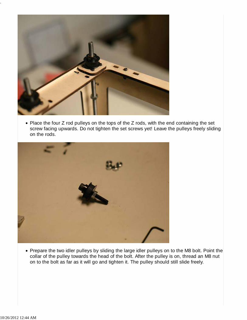
Place the four Z rod pulleys on the tops of the Z rods, with the end containing the setscrew facing upwards. Do not tighten the set screws yet! Leave the pulleys freely slidingon the rods.
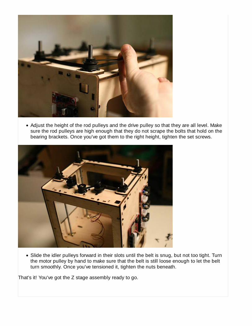
Prepare the two idler pulleys by sliding the large idler pulleys on to the M8 bolt. Point thecollar of the pulley towards the head of the bolt. After the pulley is on, thread an M8 nuton to the bolt as far as it will go and tighten it. The pulley should still slide freely.
.
10/26/2012 12:44 AM

Place the idler pulleys into the slots on the top panel. Use an M8 nut to loosely securethe pulley to the bot.Loosen the set screw in the Z drive pulley(Small Idler) and place it on the motor shaft.The set screw and collar should point down.
Wrap the Z belt around all the Z rods and the drive pulley. Thread it so that the idlerpulleys meet the back of the belt, pulling it to the interior of the bot.
..
10/26/2012 12:44 AM
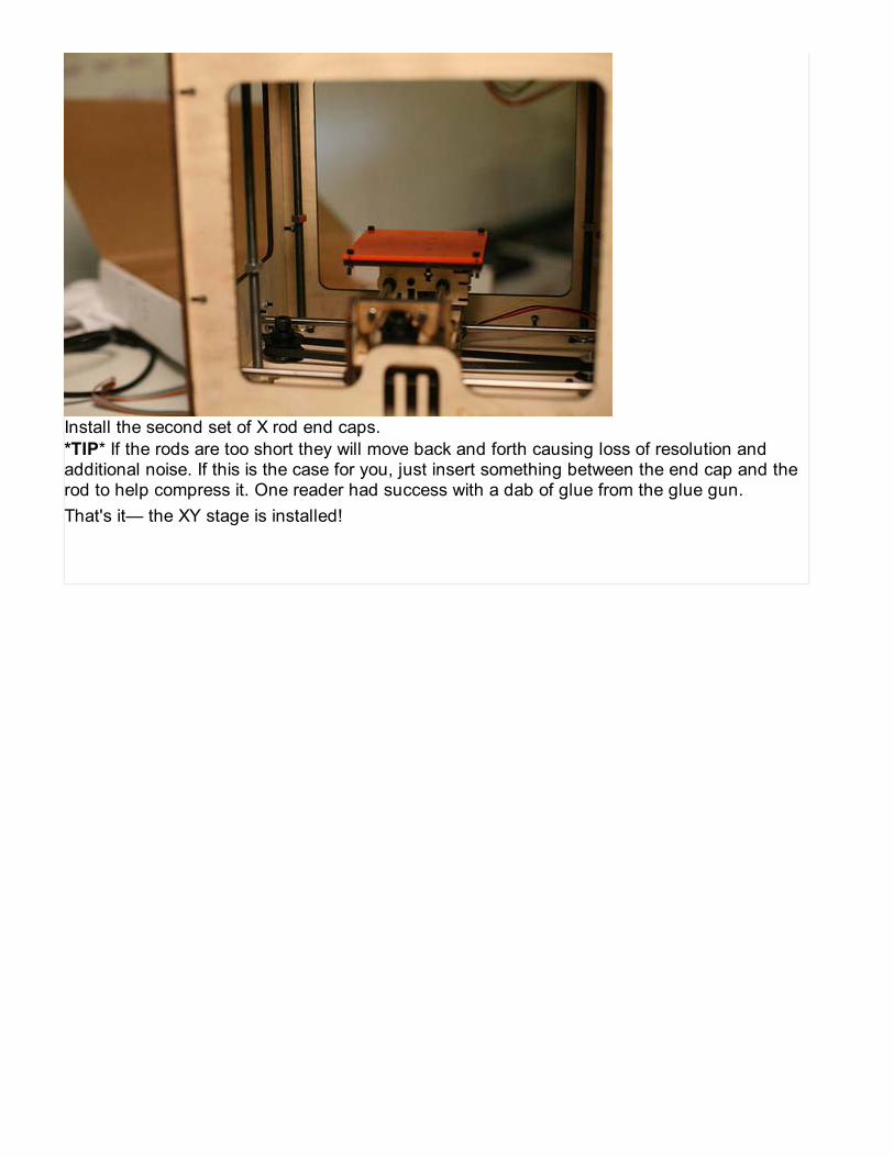
Adjust the height of the rod pulleys and the drive pulley so that they are all level. Makesure the rod pulleys are high enough that they do not scrape the bolts that hold on thebearing brackets. Once you've got them to the right height, tighten the set screws.
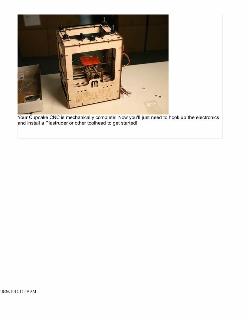
Slide the idler pulleys forward in their slots until the belt is snug, but not too tight. Turnthe motor pulley by hand to make sure that the belt is still loose enough to let the beltturn smoothly. Once you've tensioned it, tighten the nuts beneath.
That's it! You've got the Z stage assembly ready to go.

Installing the XY stage should take under thirty minutes.
XY Stage (assembled earlier)4 laser-cut rod covers (marked 'rc')2 smooth X rodsNEMA17 stepper motorsmall aluminum pulley4 M3 10mm bolts16 M3 16mm bolts16 M3 nutsM8 50mm bolt2 M8 nutsIdler pulley
The lasercut rod covers are in the Cupcake CNC Lasercut Parts box.The rods are in the Drive Rod Kit.The NEMA17 motor was bubble-wrapped with the other motors.The pulleys are in the Belt, Bearing and Pulley bag.The remaining bolts & nuts are in the Hardware Burrito bag.
.
10/26/2012 12:47 AM

Mount the small aluminum pulley on the motor shaft. The fit will be very tight, so bepatient; you may need to sand the inside of the pulley or the shaft slightly. Mount it withthe set screw side facing the motor body, with about 3-4mm between the pulley and themotor. Tighten the set screws once the pulley is position.
Install the motor in the underside of the middle plate. Place the motor so that its wires arefacing towards the outside of the bot. As always, be sure to use 10mm long bolts, not16mm long bolts! Using the wrong bolts can jam or damage your motor.
2 of 6 10/26/2012 12:47 AM

Put the idler pulley on the 50mm M8 bolt with the collar facing the head of the bolt.Thread an M8 nut on the bolt and tighten it as far as it will go.
Insert the idler pulley bolt in the slot in the left side of the middle plate of the bot. Use anM8 nut to loosely attach it, but do not tighten it.
3 of 6 10/26/2012 12:47 AM

Install two rod covers, labeled 'rc', on the right side of the bot using four bolts each.
Place the XY stage in the bot. The idler pulley on the XY stage should face the front ofthe bot. Loop the belt around the motor and idler pulleys on the bot. Position the belt sothat it runs through the wide slot in the bottom of the XY stage, and make sure thestepper wires go through the provided niche.
.
10/26/2012 12:47 AM

Insert the smooth X rods into the bot by sliding them through the holes in the left side ofthe machine, through the bearing holes in the X stage, and into the covered holes at theright of the machine. The rods should support the X stage slightly above the middleplate.
Pull the idler pulley back until the belt is fairly taut. Make sure that it's not so tight that itprevents the motor from turning and moving the platform readily. When you've got thetension about right, tighten the bolt and nut well with a hex key and a wrench.
5 of 6 10/26/2012 12:47 AM
Install the second set of X rod end caps.*TIP* If the rods are too short they will move back and forth causing loss of resolution andadditional noise. If this is the case for you, just insert something between the end cap and therod to help compress it. One reader had success with a dab of glue from the glue gun.That's it— the XY stage is installed!
6 of 6 10/26/2012 12:47 AM

Installing the Z stage should take less than ten minutes.
You'll just need the Z stage you assembled earlier.
Rotate the four free nuts on the Z rods until they are about two-thirds of the way towardsthe bottom of the rods.
..
10/26/2012 12:49 AM

Tilt the Z stage at a 45 degree angle and insert it into the bot, with the U-shaped openingfacing the front of the bot.
Move the Z stage so that two rods slide into the Z guides on the lower side of the stage.
2 of 4 10/26/2012 12:49 AM

Lower the other side of the stage so that the rods on the other end also enter the Zguides.
Now rotate the nuts so that the stage rises above the build platform. Level the platformby raising the nuts to the same height. The nuts should sit inside the hexagonal slot inthe Z platform, so that the Z guide rests on top of the nut directly. It's important to get allfour nuts to the same height, so play around a bit to make sure the Z platform iscompletely level. Turn the Z belt by hand a bit to make sure the platform smoothly risesand falls.
3 of 4 10/26/2012 12:49 AM
Your Cupcake CNC is mechanically complete! Now you'll just need to hook up the electronicsand install a Plastruder or other toolhead to get started!
..
10/26/2012 12:49 AM
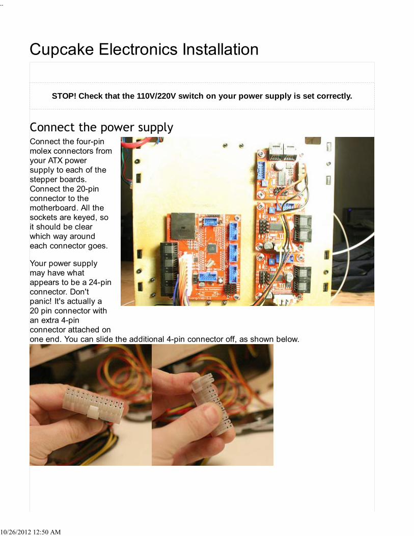
STOP! Check that the 110V/220V switch on your power supply is set correctly.
Connect the four-pinmolex connectors fromyour ATX powersupply to each of thestepper boards.Connect the 20-pinconnector to themotherboard. All thesockets are keyed, soit should be clearwhich way aroundeach connector goes.
Your power supplymay have whatappears to be a 24-pinconnector. Don'tpanic! It's actually a20 pin connector withan extra 4-pinconnector attached onone end. You can slide the additional 4-pin connector off, as shown below.
..
10/26/2012 12:50 AM

After that, find the molex connectors among the power supply wiring. The molex connector is achunky 4-pin connector with a trapezoidal tip. It's the kind of power connector that plugs intoan internal cd-rom drive in a computer, if that helps. Hook one 4-pin molex power connector upto each of the 3 stepper motor drivers. If you have a relay board, that also gets a molex. Bemindful that it is inadvisable to chain y-splitters — if you have multiple y-splitters, then connecteach one to a separate molex plug off of the power supply. We advise that the Relay Board kitbe served directly by the power supply when possible.
If you haven't done so already, assemble the ribbon cables that came with your stepperdrivers. the directions on the RepRap wiki for details. Make sure that both ends of the cableare hooked up in the same way— the engraved arrow on the IDC connector should line upwith the same colors on both ends.
NOTICE: DO NOThook the StepperMotor Drivers up to theMotherboard with theCat5(ethernet)patchcables. This causesyour Stepper Driversto become damaged.Bad news!Use the ribbon cableswith the IDC socketsto connect the stepperdriver boards to thelabeled X, Y, and Zconnections on themotherboard.
.
10/26/2012 12:50 AM

Attach the stepperconnectors on themotherboard to thecorresponding driverboards for each of theX, Y, and Z axis. Oneside of each connectorshould have a coupleof small triangularramps on it; theseshould meet thecorrespondingprotrusions on theboard when theconnector is the rightway around.
If you haven't assembled your plastruder yet, go here.
Plug one end of a patch cable into any of the RJ45 jacks on the motherboard, run it throughthe holes in the corner of the machine as shown, and plug the far end into the extruder.
.
10/26/2012 12:50 AM

The Extruder contains certain parts that could bedangerous if used in an improper manner. The extruder tipcan become extremely hot. (>250 celsius) There is also anextremely powerful motor that can pinch fingers. Makesure you always run the extruder fully assembled and thatyou never touch the hot metal tip. Always keep theextruder away from flammable objects and never leave ithot unless you are actively printing.
The Plastruder is the 'print head' for your MakerBot. You can think of it as asouped-up, robotic hot glue gun. Its main purpose in life is to heat up theplastic you feed it, and then extrude it out in a fine stream that you can buildwith. It has two main parts: the filament drive mechanism, and the heaterbarrel assembly. The filament drive mechanism is the part that grips theplastic and pushes it into the heater for extrusion. The heater barrel assemblyis the hot part of the extruder that melts the filament. It also has a smalldiameter nozzle where the hot plastic is forced out.
Specifications:
Accepts 3mm plastic filamentMaximum extrusion rate: 16mm/secondMaximum temperature: 260C
Usable Plastics
ABS - recommended polymer. cheap, ubiquitous, low shrinkage, strong objects. ABS ==Acrylonitrile butadiene styrene.PLA - excellent polymer. made from corn, transparent, eco-friendly, biocompatible andbiodegradable in the body. PLA == Polylactic acid.HDPE - cheap polymer. very smooth, relatively high shrinkage factor. HDPE == Highdensity polyethylene.CAPA - fairly expensive polymer. very low melting point. low friction. CAPA, aka PCL ==Polycaprolactone.
Gathering all the parts for building one of these can be pretty time-consuming. Also, you haveto buy a large amount of something (like Nichrome) when all you need is small amount. Notonly that, but buying a kit from the creators supports us so we can make it better. That's whywe offer a kit that contains everything you need to build one yourself.
1 of 4 10/26/2012 12:52 AM

You may buy aPlastruder MK4 kitfrom the MakerBotStore.
Building the extrudertakes about 2 hoursfrom start to finish. It'sa pretty straight-forward process whereyou bolt togetherparts, use tape, cutand solder wires, andother fairly simpletasks. We've simplifiedthe extruder design sothat it only requiressimple, common toolsto assemble. If youhave a partner orfriend to help you out,it will be much morefun.
View the assemblyinstructions here.
Your finished extruder is a robust, solid device for extrusion. If you treat it properly, it willextrude for a long time. There are certain things you should know about your extruder in order
2 of 4 10/26/2012 12:52 AM

main-assembly_display_small.jpg
to avoid damaging it.
1. Never run the motor without extruder being hot.2. Never feed in a second strand of filament.3. Always turn off extruder when you are done printing.4. Double check the target temperature before extruding.5. Never let your filament run all the way into the extruder.
View the usage instructions here.
The design of this extruder is 100% open source. Whatthis means is that we've released all the CAD files used forparts and the documentation under free licenses. Themajority of the files are DXF files created by QCad. Thereare a few different ways you can access the files:
Thingiverse - download the source, talk about it, etc.Google Code - download the release.Subversion - direct link to the MK4 release tag.
There are a number of things that can be adjusted and tuned to get a plastruder to work justright.
Top of the plastruder!
Filing the hole - Early machines didn't let you tighten the wheel close enough for thefilament to get a strong grip. The fix is to file the hole for the M8 bolt that holds theretainer wheel.Tensioning - Check the pressure on the filament with the 2mm measuring stick. If youdon't have one, you can try the flat sides of a hex key for an m3 nut (about 2.5mm)Floss the teeth - Plastic can build up between the teeth on the plastruder drive pulleywhich results in an innefective grip on the filament. Take the motor out and use a needleto scrape the plastic out.
Bottom of the plastruder
Small thermistor- (A "small" thermistor is 1mm (1/25") or smaller in diameter; a "large"thermistor is around 3mm (1/10"). The small thermistor is different and requires that youeither raise the temps to from 220 to 235 in the raft section of skeinforge, or update yourextruder board firmware after changing the values inArduinoSlaveExtruder/ThermistorTable.cpp accordingly. (see this thread for more info.)New — you can now upload the v1.8 extruder firmware and adjust the thermistor settingsdirectly from ReplicatorG. See our page on adjusting the thermistor settings.Check the resistance of the nichrome wire. It should be 6 ohms. You'll need a multimeterfor this. A lot of people skip this step when building their machine and regret it later.Check placement of the thermistor, it should be very close to the tip of the nozzle.Continuity check. Check the nichrome wire and see if it's burned through it's protective
3 of 4 10/26/2012 12:52 AM

sleeve and is grounding out.Make sure your using some heavy duty wire for the connection from the nichrome wire tothe board, otherwise it will heat up too and cause problems! One pair of twisted pairethernet seems to work nicely.
4 of 4 10/26/2012 12:52 AM

Estimated build time: 2 hours.
Wire cuttersWire strippersSoldering ironScissorsNeedle nosepliersM3 and M8 hexkeysM3 and M8wrenches or anadjustablewrenchSuper glueAcrylic glue ifyou have itA knife
10/26/2012 1:35 AM

10/26/2012 1:35 AM

Plastruder MK4http://www.thingiverse.com/thing:964
Part List: tree | flat | csv
Part QtyPlastruder MK4 Hardware Kit 1
M8 x 35mm socket cap bolt 1M8 nut 1M8 washer 2M6 Nut - Thin 1M5 x 14mm socket cap bolt 4M5 nut 4M3 x 50mm socket cap bolt 6M3 x 20mm socket cap bolt 3M3 x 16mm socket cap bolt 14M3 x 8mm socket cap bolt 1M3 Spacer - 1/2" Length 4M3 nut 30M3 washer 10
The plastruder kit contains a few more pieces than most users will actually need. In particular,your kit may contain:
An additional idler wheel. Overtensioning your idler wheel can cause it to crack or break;
10/26/2012 1:35 AM

we include a spare so you can replace it if it gets damaged. You can also use it to build adouble-idler wheel (see below for more info).A RepRap Insulator Retainer plate. These are special plates for mounting the PlastruderMk3 on a RepRap machine. If you're building a Cupcake CNC, you won't need this piece.(Likewise, if you only intend to mount your plastruder on a RepRap, you won't need thebig and little dino assemblies!)Extra 5mm LEDs and through-hole resistors. These are included for experimenters whowant to add more blinking lights to their extruders; they're completely optional.
The build process is much easier if you build all the sub-components first, and then assemblethem all into a nice, working extruder in one shot. Things like the Dino's are easiest to makebeforehand, and other things like the Idler Pulley need time for the glue to dry.
We ship the acrylicpieces with theirprotective plasticintact. This preventsthem from gettingscratched or scuffedduring shipping. Useyour fingernail, a smallflat-head screwdriver,and/or your teeth tocatch and edge andpull the blue film off.The parts are actuallyclear acrylic. Bothsides have the film onthem.
The film often getsstuck in loop letterparts (o, p, e, etc.);you can scrape it outfor a perfectly clearlook or leave it in toremind yourself of high school notebook doodles during boring classes.
Parts You'll NeedNOTE: in later batches Weird Dino Left and Weird Dino Right are called Weird Dino Front andWeird Dino Back.
Weird Dino LeftWeird Dino Right
10/26/2012 1:35 AM

Dino SupportDino BottomMountDino Top Mount7 x M3 Nuts(only 5 in kit youmay be 2 short)7 x M3 x 16mmBolts (only 5 inkit you may be 2short)2 x M5 Nuts
Assemble the PartsThe dino brackets liftthe extruder housingup so that you get themaximum build heightpossible. They arevery simple t-slotassemblies. It'seasiest if you sloteverything together,and then insert thenuts/bolts.
First, assemble theneck of the dino. Putthe left and right sidestogether over the DinoSupport piece.
Next, plug thatassembly into theBuild Base. The textshould be facingtowards the bottom.
Assemble T-slotsNow, insert bolts into each of the t-slots. You'll also want to screw in M3 x 16mm bolts as well.
5 of 45 10/26/2012 1:35 AM

Don't tighten thingsdown yet, the dino'sneed to be a bit looseto fit over the extruderhousing later.
Attach Bottom MountNow is a good time toattach the bottommount. Use Acrylicglue here instead ofsuper glue if you haveit - you'll get a muchbetter joint. Put a dabof superglue in themiddle of the plateand snap it on overthe bolt heads that aresticking out. Let it sitfor a few minutes andthey'll be permanentlyconnected.
The dino brackets use captive nuts to make attaching them to the base easier. Take two M5nuts and drop them into their respective places. They may fall out, so feel free to hold off onthis step until you're ready to attach the extruder to the build base.
10/26/2012 1:35 AM

Parts You'll Need
Big Dino LeftBig Dino RightDino SupportBig Dino BottomMountBig Dino TopMount7 x M3 Nuts(only 5 in kit youmay be 2 short)7 x M3 x 16mmBolts (only 5 inkit you may be 2short)
Assemble It!
10/26/2012 1:35 AM

The big dino is justlike the weird dino butwith a different neck.Follow the directionsabove to build it.
The idler wheel is thepart that rotates alongwith the filament andkeeps things moving.
You'll need:
The Idler WheelA 608 skatewheel bearing2 x M8 washersSuperglue
NOTE: You may alsowant to consider the"Double Idler Wheel"technique. See here:DoubleIdlerWheel-WhenThingsGoWrongand here:
DoubleIdlerWheelDiscussion
The assembly instruction are very very clear that the smooth end goes into the nozzle? If that'swrong then the assembly page needs to be corrected. Mine is constructed this way and beforethe retaining ring broke was extruding very nicely. I'll update the list shortly now I have
10/26/2012 1:35 AM

replacements and will be back up this weekend.
Position Idler WheelThe first step is toposition the idlerwheel on the bearingin the exact rightposition. This iseasiest to accomplishif you use two M8washers to space thewheel off the table abit. Position the idlerwheel over the 608bearing and push itdown until it hits thewashers.(Don't force itif the bearing does notwant to go into theidler wheel, justenlarge the hole withsome sandpaper.Forcing the bearinginto the idler wheel willcause the wheel tobreak). Use apermanent marker to write radial lines all around the idler wheel. This will help when testingthe idler wheel (below) and also in case you get extrusion slow downs later.
A bearing press (or vice with flat surfaces) allows you to put the bearing in to a much tighterfitting idler wheel without breaking it. Remember to press slowly.
Glue Idler Wheel DownOnce you have it properly in place, it needs to be glued down. Apply some superglue aroundthe inner edge of the idler wheel to glue it to the 608 bearing. Be very careful not to get any onthe inside of the bearing. You only want to glue it to the outer ring of the bearing. Let it sit forabout a half hour or so.
9 of 45 10/26/2012 1:35 AM
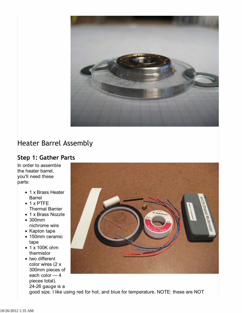
In order to assemblethe heater barrel,you'll need theseparts:
1 x Brass HeaterBarrel1 x PTFEThermal Barrier1 x Brass Nozzle300mmnichrome wireKapton tape150mm ceramictape1 x 100K ohmthermistortwo differentcolor wires (2 x300mm pieces ofeach color — 4pieces total).24-26 gauge is agood size. I like using red for hot, and blue for temperature. NOTE: these are NOT
10/26/2012 1:35 AM

included in the Plastruder kit; you must supply your own.some solder2 x crimp-on ferrules for wirea multimeterThin M6 nut (optional)
First up, you'll want to prepare the nichrome wire. Nichrome is nickel/chromium alloy with a setresistance. What that means is when you pump electricity through a length of it, it heats up. Ifyou use the right length, and the right voltage you get simple, cheap heater. Thats what we'regoing to build now.
Trim and Strip the NichromeThe nichrome wireshould have aresistance ofapproximately 6 Ohm.Usually this amountsto about 300 mm ofwire, but use amultimeter to be onthe safe side.Cut the nichrome wireto a length whichamounts to about6 Ohm of resistance(+/- 1 Ohm).NOTE: It's difficult tomeasure theresistance of thenichrome until youstrip the ends, so cutit long, then trim itdown until you reach 6Ohms.NOTE: Make the wiretoo long, and your heater takes longer to heat up. Make it too short, and you burn out theMOSFET on the extruder board.
Take your length of nichrome and strip the insulation. The easiest way to do that is to use theedge of a knife and drag it along the insulation. Don't try to cut the insulation, but insteadscrape it off. Scrape both sides of the nichrome wire and the insulation will easily fall away. Dothis on both sides of the nichrome so that around 3mm of wire is exposed.
Strip the Heater WiresNext, strip about 3mm from the ends of the wires you will use for the nichrome. Make sure youhave a decent gauge wire as this will be carrying 2-3 amps for the heater. Its easiest if youcrimp the ferrules onto this wire first. It is important you trim the exposed end of the wire to
10/26/2012 1:35 AM

3mm. That way itwon't take up all thespace in the ferrule. Ifyou mess up, its okay.You only need 2ferrules and weprovide 10 in a kit.
The next step willdepend on whichcrimp connector camewith your kit. Somekits will containcylindrical ferrules,and others will containterminal crimp pins(which have a springymetal curl at one end).Follow the directionsbelow which areappropriate for yourconnector.
Crimp the nichrome wire to the connectorInsert the stripped tipof the nichrome wireinto the small hole inthe back of theterminal connector asshown. A little bit willstick out at the top;bend it back over theconnector.
Now crimp the connection by squeezing the curled end of the connector flat with a pair ofneedle-nosed pliers.
10/26/2012 1:35 AM

Crimp the copper wire to the connectorInsert the copper wireinto the other end ofthe connector, asshown.
Use pliers to crimp the connector to the wire.
10/26/2012 1:35 AM

Solder the ConnectionBecause I don't trustmechanicalconnections, I like tosolder the whole thingin place. Nichromemetal is pretty muchimpossible to solder,but the ferrule andcopper wire are easy.The solder will providea bit more stability andmake the connectionnice and strong.
NOTE: I had noproblems solderingthis. Perhaps I found ittrivial to solder as Itend to use lead-freesolder which behavesa little differently thanthe typicallead-endowed junk.That said, it's not like it hurts anything to go solder crazy on a connection like this.
If the crimp connector doesn't work for you, try this Alternate Nichrome Soldering Technique.
10/26/2012 1:35 AM

Insulate the ConnectionYou'll want to do thisso that you have awire-nichrome-wireassembly. Once youhave that, then wrap atiny bit of Kapton tapearound the joint toinsulate it. Your heaterwire is now ready tobe attached. Win!
Repeat the sameprocess with the otherend of the nichromewire and the otherpiece of the samecolor of wire.
Separate Thermistor LeadsNext up: thermistorwire assembly. This ismuch easier. First,grab out thethermistor. The wiresare un-insulated, soour first goal is toseparate them toprevent shorts. Pullthem apart so they arenot touching and areseparated by about3mm. Don't pull toohard you pull it in half.The keyword here is'gentle'.
Trim and Tin
10/26/2012 1:35 AM

Once they areseparated, you'll wantto trim the leads to alength of 25mm. Takeyour soldering ironand apply a bit ofsolder to each end ofthe lead. This is called'tinning' the leads.We'll do the samething to the wires we'dlike to connect andthen we'll melt themboth together at thesame time to make asolid connection.
In order to do that,you'll want to strip theends off the other setof wires you have.Make sure you'reusing different colorsthan the wires for the heater! Tin the end of these wires with some solder as well.
Solder Them TogetherOnce both the wiresand the thermistorleads are tinned,you're going to want toconnect one wire toeach thermistor lead.This can be a bitfidgety, so if you canweight them downwith your pliers orsomething, it will bemuch easier. Placethem together andheat up the solder onboth of them. You maywant to apply a bitmore solder as you dothis. When it melts,remove the heat andboth wires should besoldered together.
Insulate the Joints
10/26/2012 1:35 AM

After that is complete,wrap a tiny bit ofKapton around thesolder joints. This willkeep them fromshorting out and mayadd a bit ofmechanical stability.
Isolate the LeadsTake two more shortpieces of Kapton Tapeand tape from theglass bead to thesolder joints. Thepoint of this is to keepthe thermistor leadsapart so they don'tshort (and give youbad temperaturereadings). Put tape onboth sides so itscompletely insulatedand safe, and thenyour thermistor isready for action.
Thoroughly Clean Parts
10/26/2012 1:35 AM

Sometimes the heater barrel / thermal barrier / nozzle will have debris from the machiningprocess on them. You'll want to wash all of these parts in water and/or rubbing alcohol. Theheater barrel especially will need cleaning. Once you've washed them, I also like to clean thebarrel out with a Qtip or other long stick thing that you can jam down it to push out any debris(like metal shavings.)
Assemble Machined ComponentsWe don't want anyshorts on the metalheater barrel in casethe Kapton we used toinsulate the solderjoints falls off. Theeasiest way to do thisis to assemble theThermal Barrier,Heater Barrel, andNozzle.NOTE: Your barrelmay have one endthat isdressed/tapered, andone end that is simplysawcut. The "pretty"end is the one thatgoes into the PTFEbarrier - the jointbetween the barreland the barrier has tobe clean and tight. Aspart of that, make sure that the barrel is screwed in tight, not just snug - need to make surethere isn't a gap at the top.
***NOTE: Newer barrels have one end with a smooth shoulder that is turned down to about4.5mm for about 2mm. There has been a lot of debate about which orientation is better. Bresuggests that the end that is smooth for about 2mm goes into the PTFE, not the nozzle.
This is the correct way.
10/26/2012 1:35 AM

**Make sure you tighten the heater barrel all the way into the thermal barrier (but do notovertighten, see below). Failure to do so may cause extrusion failure due to plastic filling thegap between the heater barrel and thermal barrier.
Don't go all crazy and use a vise to screw them together either. The goal here is to make surethere's no gap inside, but not to cut into the PTFE so deeply it deforms it. If you want to bereally sure, check the drawings in thingiverse and look at how they are suppose to mate insidethe PTFE, and check the length of the barrel that should be sticking out. It may help to put apiece of raw filament all the way through the insulator and into the barrel while you aretightening them together. This may help you from over tightening the barrel and deforming theedge of the hole causing the opening to narrow.
Go ahead and add the supplied M6 nut onto the heater barrel before you thread on the PTFEthermal barrier. Later, when the heater is fully put together, you will unthread the thermalbarrier and the nut to add the big washer to end up with a stackup in this order: nozzle, heater,big washer, M6 nut, and finally PTFE thermal barrier. Having the nut there is crucial because ittakes the load off the thermal barrier while the extruder is at temp and running. Without thenut, the threads on the PTFE thermal barrier will eventually fail because the hot heater barrelwarms the plastic to the point that the force of the extruder motor will push the heater barrelout of the PTFE thermal barrier. Please note that after you are done assembling the heater inthe steps below and are directed to add the big washer, don't screw the nut tight against thePTFE thermal barrier, as it will still be putting some stress on the PTFE threads. Tighten it onlyto the point that it just touches the PTFE thermal barrier, or even leave a small gap.
Note that if you partially disassemble this later and reassemble it in a different order, makesure the PTFE barrel top is flush with the top of the insulator retainer before you screw theassembly back onto the plastruder body. Otherwise you will crack the insulator retainer as youtighten it to the plastruder body.
Because the M6 nut modification transfers more sress from the PTFE to the insulator retainer,every builder should print a few spare insulator retainers just in case. The digital files to printare found here: http://www.thingiverse.com/thing:1004Note: the printed ABS insulator retainer seems to be less brittle than the original acrylic one
10/26/2012 1:35 AM

anyway.
Insulate Heater BarrelOnce you do that, putone layer of Kaptontape just below thePTFE barrier, or theM6 nut if you usedone. This is wherethere would be apotential short, sothat's where we'reprotecting.
Attach One End of HeaterNow we're going to attach the nichrome heater to the heater barrel, and we're going to do thatusing Kapton tape. First, bend a right angle into the wire connecting to the nichrome justabove the joint. Then, tape that end down to the heater barrel just below the PTFE where wejust insulated the heater barrel.
10/26/2012 1:35 AM

Wind Nichrome Around Heater BarrelNext, you'll want towind the nichromewire around the heaterbarrel. The closer youget it to the nozzle,the better. Check thepicture for a goodindication of how fardown the barrel tostart. Make sure youwind it so thenichrome fits into thethreads of the barrel.You may want to usesome thermal pastehere, but its certainlynot necessary. I don'tlike it because itsmessy.
Note: There is somedispute as to whetheryou should layer thenichrome or not. Some people suggest wrapping one layer of nichrome wire. Others suggestoverlapping the nichrome wire when you get close to the nozzle. ABS (the plastic you get withyour kit) will work fine with either way, but PLA seems to work better with the nichromewrapped in one layer.
10/26/2012 1:35 AM

Finish Attaching HeaterOnce you've wrappedthe nichrome aroundthe heater barrel,carefully bring theother end back upnext to the start of thewire and secure it intoplace with moreKapton tape.
This is a good point tocheck for shortsacross the heatingwire to the nozzleusing yourmultimeter'sresistance setting.Probe one end of thenichrome wire andtouch the other probeto the brass heaterbarrel. It should read avery high resistance(from your body's own conductivity) or as an open circuit. If you read a low resistance youmust unwrap the nichrome, locate the break in the covering and insulate it with some Kaptontape. Failing to do so could release the magic smoke from your extruder electronics.
Now you'll want to secure the whole thing to the heater barrel using a decent amount of thetape. A good rule of thumb is to use enough tape so that the heater barrel + tape is even withthe nozzle.
Attach ThermistorNow that you have the heater attached, you'll want to attach the thermistor. This is whatmeasures the temperature, so you'll want to attach it directly to the nozzle. If you want to gosuper-custom, drill a tiny indentation into the side of the nozzle. If you're like me and want tokeep things simple, just tape it directly into the side of the nozzle. Use one or two layers oftape, and also tape all the way up so that the leads/wires are attached to the heater barrel. It isa good idea to attach it on the opposite side of the barrel for ease of wiring.
10/26/2012 1:35 AM

This step is not strictlynecessary, but it doesmake things look tidy,keeps your heaterwarmer, and givesbetter startup times.I'd definitelyrecommend insulatingthe heater barrel.
Trim Ceramic Tape
The first step is to trimthe width of theceramic tape ifnecessary. You want itto insulate most of theheater barrel, and onlygo down abouthalfway on the nozzle.You can go furtherdown, but it ispossible it will interferewith extrusion and printing techniques like towering.
Attach Tape To Barrel
10/26/2012 1:35 AM

Once your ceramic tape is ready to go, take a short length of the Kapton tape and use it toattach one end of the ceramic tape to the heater barrel. Wrap it around the barrel and then use2-3 layers of kapton tape to make sure it stays connected.
When wrapping the ceramic tape around the nozzle, don't pull on it too hard as it will tear…
Can you tell we loveKapton tape? It's onlythe raddest space-agematerial for buildingrobots EVER! No bigdeal.
TIP: Before adding the retainer washer, insulate the center hole with 8-10 short strips of kaptontape. This prevents the sharp edges of the washer from cutting through the insulation on yourheater and thermistor wires causing shorts, erratic extrusion, and days of frustration.
I like to save the retainer washer for last, because it makes it really difficult to do all thewrapping and rotating that needs to be done. To put it on, simply unscrew the PTFE ThermalBarrier and the M6 nut, slide on the washer, thread the M6 nut snug against the washer andthen screw the PTFE Thermal Barrier Back on. Make sure you screw the PTFE Thermal Barrierall the way back on. You may have to bend the wires down a bit to make it fit, but thats okay.NOTE: Be extremely careful to make sure you are unscrewing the PTFE barrel and not thenozzle, or else you will wreck the whole assembly and need to start again. If you are worried,you can always put the washer on first. Once the PTFE Thermal Barrier has been threaded on,unthread the M6 nut a bit to back it off of the big washer and snug it gently against the PTFEThermal Barrier.
10/26/2012 1:35 AM

10/26/2012 1:35 AM

The filament drivemechanism is astacked assemblymade up of 6 plates.These plates arelaser-etched with anumber in the upperleft corner. They arenumbered insequence. The bottomplate is #1 and the topplate is #6. I havelabeled them A-F inthe pictures to makethem easy to see.
motor1.5mm hex key2.5mm hex key1 M3 x 8mm bolt3 M3 x 20mm bolts1 M8 x 35 mm bolt1 M8 nut2 M3 nuts2 M8 washersthe aluminum pulleythe 606 bearingassembled idler wheelassembled dinosheater barrel assembly
The pulley is the part that 'bites' into the filament and physically pushes it into the heaterbarrel. Its very important that the pulley is very firmly attached to the motor shaft.
This is fairly easy to accomplish with the pulley that we use. It has two set screws that lock thepulley onto the shaft. First you should position the pulley onto the shaft properly. The setscrews should be on the bottom towards the motor. The pulley itself should be close to thebottom of the shaft, and one of the set screws should be directly above the flat side of the
10/26/2012 1:35 AM

shaft.
Screw both of the setscrews down and thentighten the proverbialdaylight out of them.
The 606 bearing is thesmaller of the 2bearings in the kit andhas a 6mm innerdiameter to match themotor shaft. Thisbearing will take thebrunt of the force fromthe compression ofthe filament duringnormal operation. Thisis one of the majorimprovements to theMK4 design and willlead to longer motorlife and better overallperformance.
Simply push thebearing on over themotor until it is up nextto the pulley. If it is atight fit (thoughnothing like the tight fit of the motors you encountered while building the Cupcake), you mayneed to gently tap it into place.
The bearing will only be partway on the motor shaft when finished, but this is fine.
10/26/2012 1:35 AM

Grab out your trustyM3 hex key and oneM3 x 8mm hex bolt.You'll also need themotor and the motormount acrylic piece.Although there arefour holes, you onlywant to put one boltthrough the rightmosthole. Line up all theholes with the motorholes and tighten itdown. More bolts willgo in the other holeslater.
Make sure to have thewires from the motorcoming off to the righttowards the rest of theextruder housing asshown in the picture.
Note: Newer batches may not have this screw hole. They just rely on the 3 screws used in step12. Just continue without screwing in this screw if there is no hole for it. Older batches mayalso benefit from leaving this screw out as it allows fast removal of the motor to clean chippedplastic out of the gear teeth.
The spacer plate adds space to the body. It only fits on one way, so just stack it on.
Note: Newer batches may not have the hole depicted for the motor screw.
10/26/2012 1:35 AM

This plate also juststacks up on top ofthe others. The textshould be towards thetop and legible fromyour point of view.
This is a two-part plate. There is a left side piece and a right side piece. The left side piecegoes over the motor/pulley, and the right side goes over the big open space. The text shouldbe towards the top as usual.
10/26/2012 1:35 AM

These nuts are verycrucial for attachingthe heater barrelassembly. There aretwo little rectangleslots towards thebottom of each fo thefilament guides.Simply place one nutin each and you'redone!
This plate fits on over the other plates. Lay it on top and you're done!
10/26/2012 1:35 AM

Take the assembledIdler Pulley that youmade in a previousstep. Put one M8washer down on theinner area over the8mm slot. Then placethe idler pulley, andthen place anotherwasher over that.You'll want to do aquick sanity-check tomake sure that theidler pulley can easilyslide between theflanges on the pulley.If it does, you insertedit correctly. If not, tryflipping the idlerpulley over. If that stilldoesn't work, tryjuggling the washersaround until you haveit at just the right level.
Check the Pulley Alignment!
10/26/2012 1:35 AM

Once you do, makesure all thewashers/pulleys lineup over the 8mm slot.You'll be putting a boltthrough there veryshortly to keepeverything in place,but until then it will bea bit wobbly.
The retainer plate isthe top layer of thesandwich. Place it onthe top of the stackwith the text facing outand on the top. Bevery careful not todisturb the idlerbearing. If youmanage to move themout of place, take theplate off and put themback in place.
The retainer plate isthe final plate andshould snap over the606 bearing and lock itinto place.
Now, you'll want to put the M8 hex cap bolt through the back of the Motor Mount and then puta nut on it. You don't need to tighten it down yet, so just hand-tighten it so that nothing fallsout. We'll be putting more M3 bolts on in a second, and those will align everything.
10/26/2012 1:35 AM

Grab the M3 x 20mmbolts (there should be3 of them). Insert themthrough the threeholes around the 606bearing so that theygo through all of theplates to meet themotor. Use your M3hex key to tightenthem down and boltthe whole assembly tothe motor. Do notskip this step.
You'll need:
4 x M3 x 50mm bolts
10/26/2012 1:35 AM

4 x M3 nuts
4 x M3 washers4 x M3 x 1/2" spacers
The dinosaurs are theparts that elevate theextruder to give youmore build area. Theweird dino attaches tothe left of the extruder,and the big dinoattaches to the right ofthe extruder. Makesure the dinos areloose before youattempt to attachthem, otherwise youmay break themaccidentally.
Put the M3 boltthrough the back ofthe dino, then thread it through the entire housing, and finally out the front of the dino. Put a1/2" spacer over the exposed bolt, followed by a washer, and finally a nut. Repeat this for theremaining three corner holes and you'll have a mostly assembled plastruder.
Once you have everything assembled, you can tighten everything down a bit, except for theM8 bolt.
This is one of the other major innovations in the MK4 plastruder. We tested dozens of pulley toidler distances and found that 2.0mm is the ideal distance for optimum grip strength.
Simply insert the included length of steel rod into the gap between the idler wheel and themotor pulley. With your fingers, push the pulley up next to the idler wheel and then carefullytighten down the M8 bolt while making sure that the idler pulley does not slide out of position.If you made sure to sandwich the idler wheel between two M8 washers, then you will be ableto really tighten down the idler wheel without breaking anything.
Once you have the idler wheel locked into place, pull out the steel measuring stick and put itsomewhere safe. If you have it the right distance, you'll feel it slide against the idler wheel andpulley as you pull it out. If there is no resistance, or if there is quite a bit of resistance, then youeither have it too loose or too tight. Loosen the M8 and give it another try.
Pro tip: If you position your M8 wrench as shown in the picture, you can lightly push upagainst the dino in order to keep the idler wheel snug up against the pulley while you tightendown the M8 bolt with your hex key.
NOTE: This is good time to measure the small hole at the top of the PTFE barrier with calipers.If you make the idler wheel too tight, it can deform the filament stock too much and cause it to
10/26/2012 1:35 AM

be wider than the holein the PTFE, whichcan lead to extruderjams. When you startusing new filamentstock, it might be agood idea to put ainch or two throughthe pinch wheel thenback it out andmeasure it to ensurethe squished filamentis not too wide to fitinto the PTFE thermalbarrier.
The extruder controller board should fit onto the ends of the 50mm bolts. Depending on howconfident you are with your assembly skills, you will want to bolt it on with 0-4 nuts. If you feellike you're a rockstar and built it perfectly, use 4 nuts. If you feel like you may be taking it apartagain soon, use 1-2 nuts. It will actually stay in place pretty well with zero nuts, but its not a
10/26/2012 1:35 AM

good idea to run it likethat.
AlternativeArrangement: SomeMakerBot Operatorswill prefer to mountthe controller boardsomewhere else. Thiscan provide a clearline of sight withplastic as it is pulledthrough thePlastruder.
Some of you may notneed this line of sight,but it can be extremelyhelpful for debugging.As you can see fromthe image, one optionis to mount it with abunch of hot glue (orwhatever else youthink is safe).
If you go with anotherlocation, just BESURE that you're notgoing to have thecontroller crashing into your MakerBotcasing.
You'll need:
10/26/2012 1:35 AM

2 * M3 x 50mm bolts2 * M3 x 16mm bolts1 x Insulator Retainer1 x Heater Barrel Assembly1 x Retaining Washer6 x M3 washer6 x M3 nuts2 x zipties
Take 2 M3 x 16mm bolts, and 2 M3 x50mm bolts and put them through theInsulator Retainer piece. The 50mmbolts should go backwards through theRetainer holes near the text and theone directly opposite it (top and bottomif you are reading the text).
The 16mm bolts should go through theholes on the left and right if reading thetext, but the M3 16mm bolts are toolong to fit into the casing and securethe Retainer tightly. Before insertingthe 16mm bolts, screw on a M3 nutall the way to the head, then, add aM3 washer. This will allow correcttightening of the retainer assembly. Becareful not to tighten these bolts toomuch, or you can break layer #4.
Finally, put the M3 16mm bolt throughthe Retainer. The additional washer andnut should enable you to tighten theRetainer properly. Also, you may wantto put some M3 nuts on the end of thelong bolts to keep them from falling out.
The Insulator retainer bolts into the captive nuts in the extruder housing. Tighten them downwith your fingers and then give them a quarter-turn with the allen key. Keep in mind that thereis a proper orientation so that the heads of the long bolts do not cause problems with thehousing and/or electronics. The short side goes towards the front.
10/26/2012 1:35 AM

First, thread a single nut all the way up onto each of the two M3 x 50mm bolts.
Now, Grab your finished heater assembly. We're now going to bolt it into place, so make surethere is a drilled washer between the barrel and the PTFE insulator.
The washer has holes that are not symmetrical. These line up with the bolts coming down fromthe insulator retainer. Slide a washer on each of the M3 bolts, then slide the heater assembly,PTFE barrier first up into place. Fit the M3 bolts through the washer and then put a washerand nut on the end of each.
10/26/2012 1:35 AM

Tighten it downRotate the nuts untilthey are holding thelarge washer snugly inplace. Make surethere is no wiggleroom between theextruder housing andthe thermal barrier.Now rotate the nutsdown from the top ofthe M3 bolts andtighten them alltogether. This will holdthe whole assembly inplace.
Take extra care here. Ifeverything has gonewell you should havevery good alignmentbetween the channelrunning down theacrylic plastruder, thePTFE thermal barrier, the brass heater barrel, and the brassnozzle. In fact, if you hold the whole assembly up to a light youshould be able to see light coming through the nozzle, exactlycentered in the channel. Checking this will ensure that your plastic filament has a very easy
10/26/2012 1:35 AM

time finding the path all the way down to the heater barrel and nozzle and that your extrusionwill be very uniform. If you cannot see light coming through the nozzle then you should loosenthe nuts, adjust, and retighten.
This is a tidying step.Bend the wires outand around the largewasher. Then zip-tieeach set to one of thebolts. You can alsouse twisty-ties, or evena short length ofsolid-core wire if youdo not have zip-tieshandy.
The first step is to cut the heater / thermistor wires to length. If you forgot which wires arewhich, you'll want to grab out your trusty multi-meter to measure the resistance of the wires.The thermistor should read somewhere >50Kohms, and the nichrome wire should readsomewhere between 5 and 10 ohms.
Run them closely along a path up to their appropriate screw terminals. Add a little bit of lengthto them, so that they hang over the back of the screw terminals, and then cut them to length.Now strip the ends of each of them and you're good.
Remember to twist the thermistor sensor wires around each other over the length of their pathfrom the plastruder to their final destination. With four motors going in close proximity there willbe plenty of opportunity for EMF-induced noise. Twist the heater wires together to keep thingstidy.
Step 2: Insert and Secure WiresThe wires for the heater are non-polar (can be inserted in any direction) as are the wires for thethermistor. Put them in their respective holes and tighten them down. The thermistor wiresshould go into the block labeled 'Thermistor', and the heater wires should go into the block
10/26/2012 1:35 AM

labeled 'B+/B-'. Themotor wires areactually polar, soinsert the red wire into1A and the black oneinto 1B.
Plug in Extruder ControllerFinally, you'll want toplug the ExtruderController into yourRepRap Motherboard.Grab an ethernetpatch cable, andyou're good to go.Please note: this is notethernet. We usethese common cablesto cut costs andprovide a robustconnection that canprovide both powerand communicationsover a single wire.
note : you may want tosolder on the 180 ohm(R1) resistor near theserial jack to properlyterminate the RS485connection, see herefor details. If you're careful, a through-hole resistor fromRadioShack will do.
10/26/2012 1:35 AM

Before mounting your plastruder in your MakerBot, it is recommended that you "bench test"the Plastruder and make any necessary fine adjustments. Spend some time fine-tuning theposition of the idler wheel in your plastruder.
Note: Thermistors are an analog component and can vary significantly between batches,particularly when operating at extrusion temperature. Some kits have shipped with a 1mmdiameter thermistor while others have a visibly different 3mm diameter thermistor, all under onemanufacturer's product code. These will likely require different calibration settings; running theplastruder without proper calibration can damage it.
For example, if your extruder is too cold the filament will not pass through the extruder and themotor will repeatedly strip filament. If the heater is running too hot, the nozzle may becomeclogged with oxidized ABS, or more likely your thermal insulator will melt and begin to leakplastic.
Review Adjusting the Thermistor Settings for instructions on how to calibrate the extrudersettings to match your specific thermistor.
Set up the Plastruder above a surface that you don't mind covering with hot meltedplastic.
1.
Hook everything up, but don't bother to mount the Plastruder in your MakerBot body yet.This means: connect the heater, thermistor, and motor to the Plastruder controller,connect the Plastruder controller to the motherboard, and connect your PC or laptop tothe motherboard with the included USB cable. (All boards should have had firmwareloaded on them in previous steps.)
2.
Turn on the MakerBot!3.Fire up the ReplicatorG software!4.Select the Machine->Driver menu, and ensure that "Cupcake" is selected.5.Select the Machine->Control Panel menu item to open the Control Panel. You should seea pop-up window that looks like this:
6.
10/26/2012 1:35 AM

Set the target temperature to 220 degrees C, hot enough to melt ABS plastic. Theheating element should switch on, and you should see the temperature shown in theControl Panel begin to rise.
7.
Wait until the nozzle temperature reaches 220 degrees.8.Set the motor PWM to 255 ("full on.")9.Feed a strand of ABS plastic filament into the plastruder.10.Click the "forward" button.11.The ABS plastic should now begin to feed slowly into the plastruder. Feel free to makemarks on the ABS plastic with a sharpie to make the movement easier to perceive. Lookat your previously done radial marks on the idler wheel. Look to see if the filament ismoving down the barrel at a good rate and also how large the indentations are in thefilament (see video).
12.
After a while, the Plastruder should begin to extrude a thin host plastic filament.13.Continue to extrude plastic for three or four minutes.14.When done, click the "Stop" button in the Control Panel. Use a hobby knife to trim theplastic filament from the nozzle of the extruder.
15.
Set the temperature back to 20 degrees, and wait for the Plastruder to cool down beforeswitching everything off.
16.
If everything works perfectly, congratulations! Go ahead and attach your Plastruder to yourMakerBot.
10/26/2012 1:35 AM

Problems to watch out for:
Ensure that the nozzle heats up.Ensure that you get a continuous, fast flow of plastic filament out of the extrusion nozzle.Ensure that the ABS plastic filament feed works reliably. If the feeding motor slips orjams, you may need to adjust the Idler Wheel.If the ABS filament slips to the side of the Idler wheel, you may need to disassemble yourPlastruder to adjust the position of the Idler Wheel and the position of the Motor Pulley.
Now that your extruder is complete, you'll want to attach it to your MakerBot. This should takeplace after you have completed assembly of the MakerBot, so do that if you haven't already.
Grab four M5 x 15 bolts. You should have captive nuts in each of the dinosaur brackets.Replace them if they are missing. Place your extruder on the Z stage with the ExtruderController facing the front of the machine.
Thread each bolt from the bottom up through the Z stage into the captive nuts. Tighten themdown and your extruder is now attached. If you need to remove it, simply unbolt them and takethe entire extruder out.
Revisit Adjusting the Thermistor Settings again with your extruder mounted in position.
10/26/2012 1:35 AM

Should you need to update the extruder firmware, instructions can be found atpage:
10/26/2012 1:35 AM

The new extruder controller firmware (v1.8) stores its thermistor settings in the on-chipEEPROM. That means you can use ReplicatorG to update and tweak the parameters for thethermistor and tune it to your specific extruder.
Since the settings are resident on the extruder controller, and are not retained in ReplicatorG,you can now tweak extruders on a per-bot basis.
This page explains how to get up and running with the new firmware, and set the parametersto useful values.
ReplicatorG 0012 includes the software support for updating the thermistor tables, so makesure you've got it installed before you begin.
If you haven't already, you should upgrade the firmware on your extruder controller to v1.8 orlater. You only need to perform this step once.
fire up ReplicatorG 0012 or later.1.plug your USB2TTL cable into the extruder controller's 6-pin header. Pay attention to themarkings on the board and be careful not to plug the cable in backwards!
2.
Select "Upload new firmware…" from the "Machine" menu in ReplicatorG.3.Select the Extruder Controller, the version to install (v1.8 or later), and the name of theUSB port your cable is using.
4.
Press the small reset button on the extruder board at the same time as you click the"Upload" button in the uploading dialog. It will take a few moments to upload thefirmware, so be patient.
5.
If you see an error message, try again; sometimes it's hard to get the timing right.6.Disconnect the USB2TTL cable from the extruder board.7.When you're done, close ReplicatorG.8.
Start ReplicatorG.1.Wait for ReplicatorG to connect to the makerbot. You won't be able to access thethermistor settings until after ReplicatorG has connected to the machine.
2.
From the "Machine" menu, select "Onboard Preferences".3.Click the "Set Extruder Parameters" buttons in the Onboard Preferences dialog.4.You'll now see the thermistor options. Enter the beta, r0, and t0 settings appropriate toyour thermistor. For a full explanation of what these parameters mean, see Nophead'sexcellent explanation on his blog. (The r2 is internally pegged at 4.7Kohms, the value ofthe resistor on the board, and r1 is infinite.) Here are a few useful settings:
5.
/26/2012 1:53 AM

Thermistor type beta r0 t0
Default "large" thermistor 4066 100000 25
Nick's "large" thermistor Settings 4198 100000 25
Zach's 1mm settings 4198 100000 25
J.E.T.'s 1mm thermistor settings 4881 93700 24
Keith's CupCake thermistor settings 3736 268000 0
Click on "commit changes".1.Reset the extruder board. There are a few ways to do this. Try one of the following:
Press the reset button on the extruder board itself.1.Turn the machine's power off and then on.2.Unplug the extruder, and then plug it back in again.3.
2.
Once the extruder board has been reset, it will be using the new thermistor settings from theEEPROM.
If you find better settings than the ones you see here, be sure to share them!
The following inputs can be used as starting points to calculating new values of beta usingWolfram|Alpha. Modify the T0, R0, R and T pairs of values as per your own measurements.
T0=25.0, R0=100000, R=6450.0, T=100.0, beta=ln(R/R0)/((1/(T+273.15))-(1/(T0+273.15)))(read LINK CAUTION)T0=25.0, R0=100000, R=5901, T=100.0, beta=ln(R/R0)/((1/(T+273.15))-(1/(T0+273.15)))(read LINK CAUTION)
/26/2012 1:53 AM
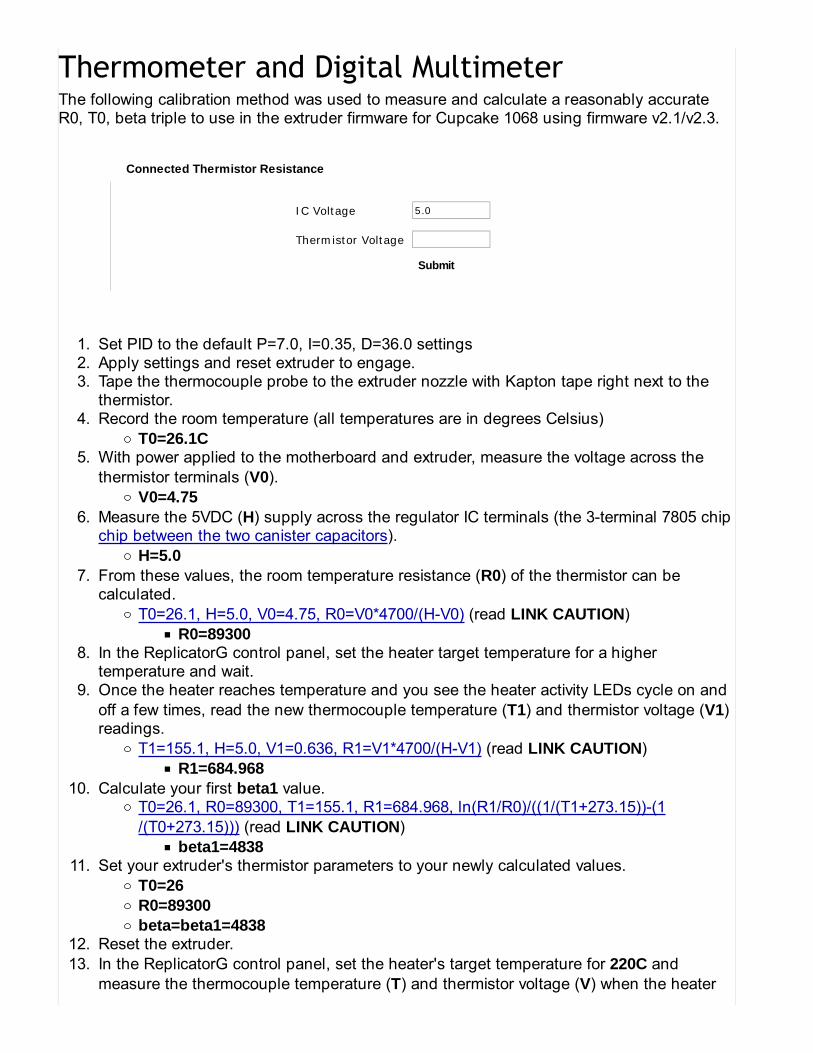
The following calibration method was used to measure and calculate a reasonably accurateR0, T0, beta triple to use in the extruder firmware for Cupcake 1068 using firmware v2.1/v2.3.
IC Voltage 5.0
Thermistor Voltage
Submit
Connected Thermistor Resistance
Set PID to the default P=7.0, I=0.35, D=36.0 settings1.Apply settings and reset extruder to engage.2.Tape the thermocouple probe to the extruder nozzle with Kapton tape right next to thethermistor.
3.
Record the room temperature (all temperatures are in degrees Celsius)T0=26.1C
4.
With power applied to the motherboard and extruder, measure the voltage across thethermistor terminals (V0).
V0=4.75
5.
Measure the 5VDC (H) supply across the regulator IC terminals (the 3-terminal 7805 chipchip between the two canister capacitors).
H=5.0
6.
From these values, the room temperature resistance (R0) of the thermistor can becalculated.
T0=26.1, H=5.0, V0=4.75, R0=V0*4700/(H-V0) (read LINK CAUTION)R0=89300
7.
In the ReplicatorG control panel, set the heater target temperature for a highertemperature and wait.
8.
Once the heater reaches temperature and you see the heater activity LEDs cycle on andoff a few times, read the new thermocouple temperature (T1) and thermistor voltage (V1)readings.
T1=155.1, H=5.0, V1=0.636, R1=V1*4700/(H-V1) (read LINK CAUTION)R1=684.968
9.
Calculate your first beta1 value.T0=26.1, R0=89300, T1=155.1, R1=684.968, ln(R1/R0)/((1/(T1+273.15))-(1/(T0+273.15))) (read LINK CAUTION)
beta1=4838
10.
Set your extruder's thermistor parameters to your newly calculated values.T0=26R0=89300beta=beta1=4838
11.
Reset the extruder.12.In the ReplicatorG control panel, set the heater's target temperature for 220C andmeasure the thermocouple temperature (T) and thermistor voltage (V) when the heater
13.
10/26/2012 1:53 AM

has settled and the activity LEDs have cycled off and on a few times.T=193.0, H=5.0, V=0.310, R=V*4700/(H-V) (read LINK CAUTION)
R=310.661T0=26.1, R0=89300, T=193.0, R=310.661, ln(R/R0)/((1/(T+273.15))-(1/(T0+273.15)))(read LINK CAUTION)
beta=4732Set your extruder's thermistor parameters to these final calculated values.
T0=26R0=89300beta=4732
14.
Reset the extruder.15.In the ReplicatorG control panel, set the heater's target temperature for 220C andconfirm that both ReplicatorG and the thermocouple report 220C.
16.
Depending on room conditions (breezes, ambient temperature, etc) you can expect to seefluctuations and minor differences between the readings, but the reading should be accurateenough now at your target extrusion temperature of 220C.
See Measuring Thermistor Beta for more beta measurement details.
MakerBot Industries: Adjusting The Thermistor Settings http://wiki.makerbot.com/printer--friendly//adjusting-the-thermistor-settings
10/26/2012 1:53 AM

This page is intended as a general guide to the operation, maintenance, and repair of yourMakerBot Plastruder.
Once you have your extruder assembled, you'll want to get started right away. It's best to takeit slow and test the various sub-systems before you do something that could potentially breakit. This will also give you a feel for how to actually use the extruder as well.
Measuring the temperature is reallyeasy. Make sure you have theextruder wired up properly to theExtruder Controller, and then openthe ReplicatorG software. It willimmediately begin polling theextruder for its temperature and willupdate the status window. It shouldread something around 20 celsiuswhich is about 68 fahrenheit.
If it reads something that doesn'tmake sense, jump to thetroubleshooting section.
If your temperature is readingcorrectly, it is now time to fireup the heater! Its best tochoose a conservativetemperature first and thenslowly build your way up. Thatway you can detect a problemand hopefully fix thereforeavoiding doing some sort ofdamage. The latest heaterdesign is pretty foolproof, soyou should be fine.
I suggest starting the heater at 50C, letting it heat up (watch the temperature and make sure itactually does rise from 20C to 50C). Let it maintain the 50C temperature for a few minutes.This will prove that it can indeed handle controlling its temperature.
1 of 6 10/26/2012 2:00 AM
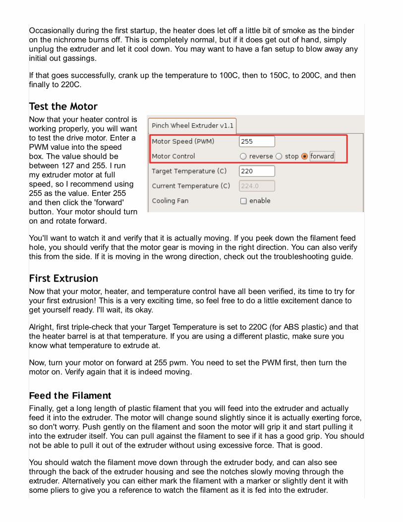
Occasionally during the first startup, the heater does let off a little bit of smoke as the binderon the nichrome burns off. This is completely normal, but if it does get out of hand, simplyunplug the extruder and let it cool down. You may want to have a fan setup to blow away anyinitial out gassings.
If that goes successfully, crank up the temperature to 100C, then to 150C, to 200C, and thenfinally to 220C.
Now that your heater control isworking properly, you will wantto test the drive motor. Enter aPWM value into the speedbox. The value should bebetween 127 and 255. I runmy extruder motor at fullspeed, so I recommend using255 as the value. Enter 255and then click the 'forward'button. Your motor should turnon and rotate forward.
You'll want to watch it and verify that it is actually moving. If you peek down the filament feedhole, you should verify that the motor gear is moving in the right direction. You can also verifythis from the side. If it is moving in the wrong direction, check out the troubleshooting guide.
Now that your motor, heater, and temperature control have all been verified, its time to try foryour first extrusion! This is a very exciting time, so feel free to do a little excitement dance toget yourself ready. I'll wait, its okay.
Alright, first triple-check that your Target Temperature is set to 220C (for ABS plastic) and thatthe heater barrel is at that temperature. If you are using a different plastic, make sure youknow what temperature to extrude at.
Now, turn your motor on forward at 255 pwm. You need to set the PWM first, then turn themotor on. Verify again that it is indeed moving.
Feed the FilamentFinally, get a long length of plastic filament that you will feed into the extruder and actuallyfeed it into the extruder. The motor will change sound slightly since it is actually exerting force,so don't worry. Push gently on the filament and soon the motor will grip it and start pulling itinto the extruder itself. You can pull against the filament to see if it has a good grip. You shouldnot be able to pull it out of the extruder without using excessive force. That is good.
You should watch the filament move down through the extruder body, and can also seethrough the back of the extruder housing and see the notches slowly moving through theextruder. Alternatively you can either mark the filament with a marker or slightly dent it withsome pliers to give you a reference to watch the filament as it is fed into the extruder.
2 of 6 10/26/2012 2:00 AM

It works!It takes about 1-2minutes for thefilament to feed all theway through theextruder and come outthe bottom. Be patientwhile this ishappening. It willdefinitely start toextrude. Eventually,you'll see your veryfirst extrusion comeout of the nozzle!Congratulations, yourextruder works! Youshould 'burn-in' yourextruder and let itextrude for 5-10minutes just to verifythat it is actuallyworking properly. Becareful that yourfilament does not pullall the way into the extruder housing as it is a bit of a pain to remove if it does.
If your extruder stops extruding during this first extrusion, check the troubleshooting guide forsteps you can take to fix this.
The basic process to replace the filament is:
1. Heat up extruder to operating temperature2. Reverse the extruder motor to pull filament out3. Pull out old filament4. Turn extruder motor on forward5. Feed in new filament and wait for extrusion
If you want to be lazy and/or efficient, here is a pre-made GCcode script that you can runwhich will prompt you for the various steps:
M104 S220 (Heat up extruder to 220C. Change if you use non-ABS)M108 S255 (Set PWM speed to 255)M06 T0 (Wait for extruder 0 to warm up)M102 (Reverse the motor)M00 (Click 'Yes' once the filament has been removed.)
3 of 6 10/26/2012 2:00 AM

M101 (Motor on, forward)M00 (Insert the filament and click 'Yes' once it starts extruding.)M103 (Motor off)M104 S0 (Temperature 0, heater off.)
It's important to keep your extruder clean for proper functioning. Always make sure you areusing clean filament with no dust or debris. You may want to have the filament pass through arag or something in order to remove the dust from it.
Also, during operation your extruder will probably pick up globs of plastic on the nozzle. Theseshould only be removed when the nozzle is hot with a pair of tweezers. You can use needlenose pliers, but be very careful that you do not clamp the nozzle as you may destroy itaccidentally.
Hopefully when you tightened down the idler wheel, you gave it a good twist. If you didn't, itmay possibly work its way loose during normal operation. If this happens, you just tighten itback up. You'll need to remove the filament before tightening.
Depending on your tools, you may need to remove the electronics to tighten the idler pulley. Ifyou have a 13mm wrench that fits between the board and the acrylic, then you can just usethat. Otherwise, off with the electronics!
The rest of the nuts and bolts should be kept tight, especially the ones holding the heaterbarrel assembly to the extruder housing. Don't tighten things too much so that the acrylicbreaks. A good rule of thumb is 1/4 or 1/3 of a turn past hand-tight.
Reality Check #1: Is your thermistor actually hooked up?
The thermistor should be wired to the two-pin screw terminal labeled 'Thermistor'.
Reality Check #2: Is it actually your thermistor?
Your thermistor should have a resistance of ~80K at room temperature. Measure the resistancewith a multimeter. If it reads low, like say 6-12 ohms, then you have hooked up the heater tothe thermistor port instead. Swap the heater and thermistor (double check the heaterresistance to make sure!!!).
If the multimeter reads as a short or as 0 ohms, then your thermistor is shorted. Unfortunately,you're going to have to take apart the heater barrel, pull the thermistor leads apart to fix theshort, and then re-assemble it.
If your multimeter reads infinite resistance, or no connection, then one of your connections isbad and you'll need to re-attach the lead wires to the thermistor somehow. This involves taking
4 of 6 10/26/2012 2:00 AM

apart and re-assembling the heater barrel assembly.
Reality Check #1: Is your heater hooked up?
The heater wires should be hooked up to the B+ and B- ports on the MOSFET output port.The polarity is not important, but it is important that its hooked up and screwed down nice andsnugly.
If that doesn't fix it, make sure that you have your heater hooked up. Measure the resistancebetween the two ends of the heater wire. It should be from 6-12 ohms, depending on thelength of nichrome you used. If it is much higher, you have hooked up the thermistor to theheater and should switch them (double check the thermistor resistance to make sure!!!)
If they are shorted, then you have a short and need to fix it. Unfortunately, you need to takeapart the heater barrel to fix it.
If that doesn't fix it, or there is infinite resistance (no connection) then one of the joints may bebad. You'll have to disasseble the heater barrel for this as well.
Reality Check #1: Is your motor hooked up?
The motor should be hooked up to output 1 of the h-bridge outputs. The red wire should behooked up to 1A, and the black wire should be hooked up to 1B.
Easy! Simply swap the red and black wires. Remember to turn the power off first!
This can be a bit tricky. There are a few tricks / techniques to make it work again. Just bepatient and you'll have a working extruder in no time.
New Extruders
If you had your first extrusion, but it stopped shortly afterwards, you might have debris in yourextruder nozzle. This happens when you do not properly clean your barrel/nozzle before usingit.
The solution is to reverse the filament, cut off all the filament from where it got chewed up andbelow, and run new filament in. The old filament that you pull out will also pull out most of thejunk that is in the extruder. Do this a couple times and it should be totally free of debris. Youmay even see tiny particles on the surface of the melted filament when you pull it out. If yousee that, then that is definitely your problem.
Does pushing on the filament start up extrusion again?
If it starts extrusion again, then awesome. Chances are that the drive gear just chewed up the
5 of 6 10/26/2012 2:00 AM

filament too much and lost traction. If you just had to push for a little bit to start extrusion andthen the extruder continued to extrude then that was your problem.
If the extrusion starts, but stops as soon as you stop applying pressure, then most likely youridler wheel is not tight enough. I recommend removing the filament, tightening up the idlerwheel, and then re-feeding the filament down through the extruder again.
Does your extruder slowly lose grip and not extrude very well?
Potential problem #1: Your heater barrel does not fix exactly into the PTFE barrel.
Some of the heater barrels in the latest batch are not beveled to match the internal structure ofthe PTFE. If you have a lathe, bevel the edge at 31 degrees (to match the standard 118 degreeangle of a jobber bit) If you don't have a lathe, you can use a file to get the desired bevel aswell To check to see if you need to do this fix, its pretty easy:
# Remove the screws holding the heater barrel assembly to the heater barrel.# Cut the filament just above where it goes into the housing.# Turn the extruder motor on forward at 255 rpm to eject the filament along with the heaterbarrel assembly. no need to heat it up, as the whole assembly will be pushed out with thefilament.# Unscrew the PTFE from the heater barrel and pull it off over the filament. If the plastic hasflattened and 'pancaked' over the heater barrel, the barrel does not match the ptfe receptacleand you'll want to bevel the edge to eliminate this gap. you'll need to heat up the heater barreland remove the filament first in order to get access and to be able to load filament later.
Potential problem #2: The idler wheel slot may be slightly undersized.
We tried to make it the perfect size, but it may be too conservative. Check the filament and seejust how deep the teeth are. I press on the idler wheel moderately hard when tightening whichmay give me an extra 0.1 or 0.2 of a millimeter. If the teeth marks do not look deep, you mayneed to widen the slots on the retainer plate and the motor plate. Unfortunately you'll need totake apart your extruder for that. Once you've done that, then file (or dremel) away the slot inthe direction of the pinch wheel pulley. That should give you the added grip to make it worknicely.
Does nothing work to start extrusion?
This could be bad. You may have a really bad blockage in the nozzle. If you're using ABSplastic, then your best bet is to take apart the entire heater barrel / nozzle assembly. Youshould then soak the nozzle and heater barrel in Acetone overnight. The acetone will dissolvethe ABS and you can then thoroughly wash the nozzle / heater barrel to remove the blockage.It may be extreme, but it does work.
6 of 6 10/26/2012 2:00 AM

Bolt the motherboardand the stepperdrivers to the side ofthe Cupcake CNC asshown, using M3x16bolts. Use the plasticspacers to put somespace between thewood and theelectronics.
STOP! Check that the 110V/220V switch on your power supply is set correctly.
Connect the four-pin molex connectors from your ATX power supply to each of the stepperboards. Connect the 20-pin connector to the motherboard. All the sockets are keyed, so itshould be clear which way around each connector goes.
UPDATE: The ATX power supply in the Deluxe kit might have a connector that looks like it hastoo many conductors. Don't worry, the extra 4 pins are in a *separate* connector that actuallyslides down off of the main 20-pin connector!
.
10/26/2012 12:54 AM

Use the ribbon cableswith the IDC socketsto connect the stepperdriver boards to thelabeled X, Y, and Zconnections on themotherboard.
Although there maybe labels on the sideof the Cupcake CNCindicating X, Y, and Z,you can hook up thestepper drivers up inany way you choose,as long as eachstepper (next step) ishooked up to the boardwired to thecorresponding socketon the motherboard. In our example, we've decided to use the bottommost stepper driver asthe Y driver, rather than the X driver, because the wires running to the Y axis stepper are justlong enough to reach that bottommost board at their full extension.
Note: Sometimes the ribbon cables do not come pre-assembled but as a cable and twosnap-on endplugs. Each endplug has a small triangle engraving on it that points to one wire inthe ribbon cable. Make sure that both endplugs' triangles point to the same color wire or youwill have to make a new ribbon cable (the endplugs never come off after you snapped them
.
10/26/2012 12:54 AM

on).
NOTE: In addition to paying attention to keeping the same color wire on the triangle, also payattention to whether or not the IDC connector is flipped upside down or not. If you get it thewrong way and are picky about your wiring, you could be very upset when the wire is comingout of the wrong side of the PCB.
Attach the stepperconnectors to thecorresponding driverboards for each of theX, Y, and Z axis. Oneside of each connectorshould have a coupleof small triangularramps on it; theseshould meet thecorrespondingprotrusions on theboard when theconnector is the rightway around.
Plug one end of a patch cable into any of the RJ45 jacks on the motherboard, run it throughthe holes in the corner of the machine as shown, and plug the far end into the extruder.
...
10/26/2012 12:54 AM

Note: Do yourself a favor and use a shielded Cat5e patch cable to keep down on EMI from thestepper motors.
That's it! The core electronics of your Cupcake CNC are hooked up. Step back and revel inyour MakerBot assembly skills!
Now is a great time to upload a picture of yourMakerBot Cupcake CNC to the MakerBotFlickr Group at [http://flickr.com/groups/makerbot] Here's the first production modelthat we made! (Number 21)
You should also head over to thingiverse andclick the "I made one" button on the MakerBotCupcake CNC page![http://www.thingiverse.com/thing:457]
Once you're done smiling and staring at your fully assembled but yet motionless machine,you'll surely want to get it moving.Don't shoot out - do this first:
Download ReplicatorG and Skeinforge at http://replicat.org/Read the Tips and Tricks page, namely the Skeinforge section.
.
10/26/2012 12:54 AM

STOP! Check that the 110V/220V switch on your power supply is set correctly.
Connect the four-pinmolex connectors fromyour ATX powersupply to each of thestepper boards.Connect the 20-pinconnector to themotherboard. All thesockets are keyed, soit should be clearwhich way aroundeach connector goes.
Your power supplymay have whatappears to be a 24-pinconnector. Don'tpanic! It's actually a20 pin connector withan extra 4-pinconnector attached onone end. You can slide the additional 4-pin connector off, as shown below.
..
10/26/2012 12:50 AM

After that, find the molex connectors among the power supply wiring. The molex connector is achunky 4-pin connector with a trapezoidal tip. It's the kind of power connector that plugs intoan internal cd-rom drive in a computer, if that helps. Hook one 4-pin molex power connector upto each of the 3 stepper motor drivers. If you have a relay board, that also gets a molex. Bemindful that it is inadvisable to chain y-splitters — if you have multiple y-splitters, then connecteach one to a separate molex plug off of the power supply. We advise that the Relay Board kitbe served directly by the power supply when possible.
If you haven't done so already, assemble the ribbon cables that came with your stepperdrivers. the directions on the RepRap wiki for details. Make sure that both ends of the cableare hooked up in the same way— the engraved arrow on the IDC connector should line upwith the same colors on both ends.
NOTICE: DO NOThook the StepperMotor Drivers up to theMotherboard with theCat5(ethernet)patchcables. This causesyour Stepper Driversto become damaged.Bad news!Use the ribbon cableswith the IDC socketsto connect the stepperdriver boards to thelabeled X, Y, and Zconnections on themotherboard.
.
10/26/2012 12:50 AM

Attach the stepperconnectors on themotherboard to thecorresponding driverboards for each of theX, Y, and Z axis. Oneside of each connectorshould have a coupleof small triangularramps on it; theseshould meet thecorrespondingprotrusions on theboard when theconnector is the rightway around.
If you haven't assembled your plastruder yet, go here.
Plug one end of a patch cable into any of the RJ45 jacks on the motherboard, run it throughthe holes in the corner of the machine as shown, and plug the far end into the extruder.
.
10/26/2012 12:50 AM

Now that all the pieces are together, time to get things calibrated for optimal performance!
Kits from MakerBot Industries ship with precision ground rods with a 10-micron finish thatdo not need to be smoothed at all. If you are supplying your own rods, you want them tobe very smooth. Sand the rod supports down with some 300 or 400 grit sandpaper andthen rub them with super super superfine steel wool
Shops specializing in auto body repair carry very fine sandpaper
1.
Apply 3-in-1 oil to rod supports2.Move the Z stage down until the printhead almost touches the build platform. Thenslowly (manually) move the build platform along both X and Y axis while observing thedistance between build platform and print head. It should remain constant. If does not,your X and/or Y axis are not exactly parallel to the build platform. Check and make surenone of the tabs or magnets or other lumps are sticking out of the top of the Y stage orbottom of the build platform. Push them in or shave them off with the supplied razorblade as appropriate. If it still isn't level, you can level it out by attaching some electricaltape to the bottom of the build platform (or to the top of the Y stage).
3.
Check the tension on the X and Y platform belts. If they are too loose, the teeth will slipon the motor pully. If they are too tight, the machine will suffer from excess vibration andacoustic noise.
4.
1 of 4 10/26/2012 12:57 AM
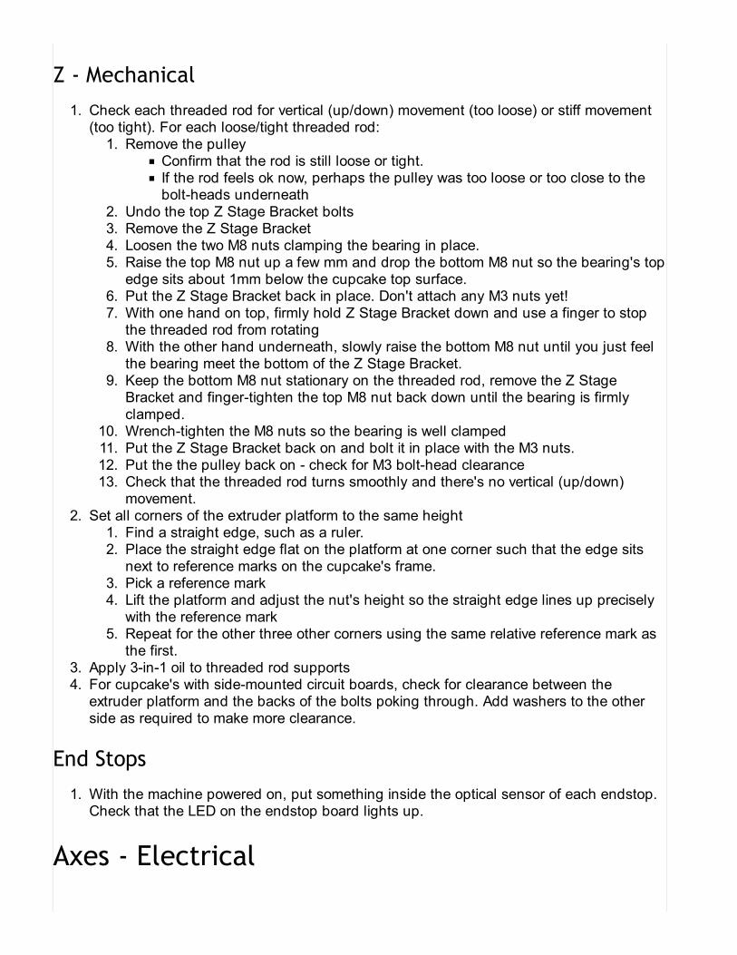
Check each threaded rod for vertical (up/down) movement (too loose) or stiff movement(too tight). For each loose/tight threaded rod:
Remove the pulleyConfirm that the rod is still loose or tight.If the rod feels ok now, perhaps the pulley was too loose or too close to thebolt-heads underneath
1.
Undo the top Z Stage Bracket bolts2.Remove the Z Stage Bracket3.Loosen the two M8 nuts clamping the bearing in place.4.Raise the top M8 nut up a few mm and drop the bottom M8 nut so the bearing's topedge sits about 1mm below the cupcake top surface.
5.
Put the Z Stage Bracket back in place. Don't attach any M3 nuts yet!6.With one hand on top, firmly hold Z Stage Bracket down and use a finger to stopthe threaded rod from rotating
7.
With the other hand underneath, slowly raise the bottom M8 nut until you just feelthe bearing meet the bottom of the Z Stage Bracket.
8.
Keep the bottom M8 nut stationary on the threaded rod, remove the Z StageBracket and finger-tighten the top M8 nut back down until the bearing is firmlyclamped.
9.
Wrench-tighten the M8 nuts so the bearing is well clamped10.Put the Z Stage Bracket back on and bolt it in place with the M3 nuts.11.Put the the pulley back on - check for M3 bolt-head clearance12.Check that the threaded rod turns smoothly and there's no vertical (up/down)movement.
13.
1.
Set all corners of the extruder platform to the same heightFind a straight edge, such as a ruler.1.Place the straight edge flat on the platform at one corner such that the edge sitsnext to reference marks on the cupcake's frame.
2.
Pick a reference mark3.Lift the platform and adjust the nut's height so the straight edge lines up preciselywith the reference mark
4.
Repeat for the other three other corners using the same relative reference mark asthe first.
5.
2.
Apply 3-in-1 oil to threaded rod supports3.For cupcake's with side-mounted circuit boards, check for clearance between theextruder platform and the backs of the bolts poking through. Add washers to the otherside as required to make more clearance.
4.
With the machine powered on, put something inside the optical sensor of each endstop.Check that the LED on the endstop board lights up.
1.
2 of 4 10/26/2012 12:57 AM

Check stepper motor directionPosition platform at X and Y axis mid-points1.Launch ReplicatorG2.Launch Control Panel3.Set step size to 5mm or smaller4.Click X+
Facing the Makerbot front panel, did the X axis move left?If yes, great!If opposite direction, use ReplicatorG to invert the direction under Machine ->Onboard Preferences
Alternatively unplug the X axis motor connector and plug it in upsidedown.[Be sure to power off to avoid damage to the stepper driver]
If it didn't move at all, check all your connections (link to general electricaldebugging reference)
5.
Click Y+Facing the Makerbot front panel, did the Y axis move toward you?If yes, great!If opposite direction, use ReplicatorG to invert the direction under Machine ->Onboard PreferencesAlternatively, unplug the Y axis motor connector and plug it in upside down[Be sure to power off to avoid damage to the stepper driver]If it didn't move at all, check all your connections (link to general electricaldebugging reference)
6.
1.
Manually position the Z-axis in the middle of the bot by pulling the belt before testing.1.Set the step size to 1mm or smaller! (Some (very) old versions of the firmware had thebot defaulting to inches rather than millimeters. Even if this has happened to you, a 1mmstep size will only move the bot an inch.)
2.
Click Z+If the platform moves up by a barely-perceptible amount, you're good!If the platform moves down, unplug the Z axis motor connector and plug it inupside down.[Be sure to power off to avoid damage to the stepper driver]or reversethe direction in the software (see note below)If the platform moves a long way up or down, update your firmware (need to tellHOW!).
3.
Once the 1mm stepping appears to be working, set the step size to 5mm and alternatebetween Z+ and Z-.
If the platform moves by a barely-perceptible amount:Confirm that nothing is blocking the movement by turning the stepper gearmanually (may need to disable stepper motors from the control panel first)On the Z Axis Stepper Driver board, turn the pot about a quarter-turnclockwise and try again - this increases the amount of current supplied to thestepper motor.
If the Z Axis Stepper Driver IC is getting very hot (don't burn your finger!):Turn the pot about a quarter-turn counter-clockwise and try again.
4.
.
10/26/2012 12:57 AM
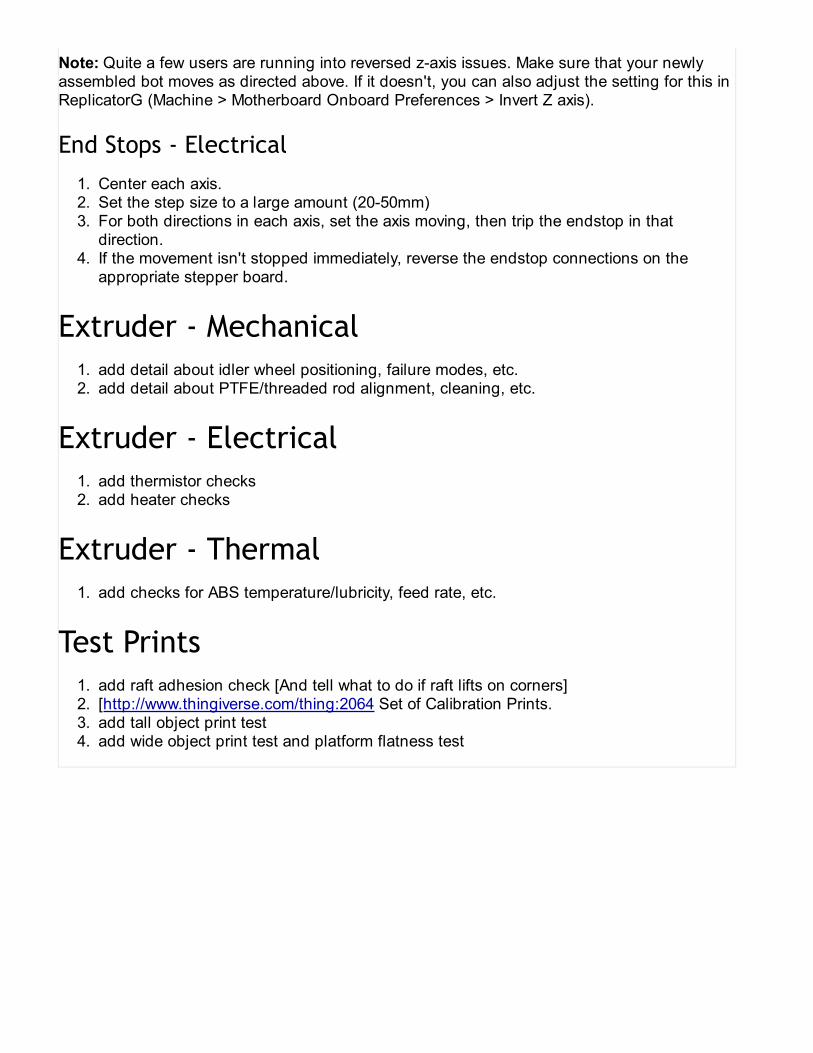
Note: Quite a few users are running into reversed z-axis issues. Make sure that your newlyassembled bot moves as directed above. If it doesn't, you can also adjust the setting for this inReplicatorG (Machine > Motherboard Onboard Preferences > Invert Z axis).
Center each axis.1.Set the step size to a large amount (20-50mm)2.For both directions in each axis, set the axis moving, then trip the endstop in thatdirection.
3.
If the movement isn't stopped immediately, reverse the endstop connections on theappropriate stepper board.
4.
add detail about idler wheel positioning, failure modes, etc.1.add detail about PTFE/threaded rod alignment, cleaning, etc.2.
add thermistor checks1.add heater checks2.
add checks for ABS temperature/lubricity, feed rate, etc.1.
add raft adhesion check [And tell what to do if raft lifts on corners]1.[http://www.thingiverse.com/thing:2064 Set of Calibration Prints.2.add tall object print test3.add wide object print test and platform flatness test4.
4 of 4 10/26/2012 12:57 AM

Endstops are optical switches that are installed at either end of each axis of motion. Endstoptriggers which protrude from the stages fit into the slots in the switches when a stage moves allthe way to one end of its travel. The endstop serve two purposes:
to allow Cupcake CNC to calibrate itself when it first starts working, to make sure it hasmoved the build stages to the correct locations, andto shut off a motor if for some reason the firmware goes haywire and a stage tries tomove too far in one direction.
A word on optical endstop reliabilityOne of the reasons we're transitioning away from using these endstops is that they can gettriggered by all sorts of odd conditions— for example, some of the triggers go off if the bot issitting in direct sunlight! If you're getting strange behavior with your endstops, check yourambient lighting conditions.
A brief note on going too farIt's actually possible to run the Cupcake CNC with no endstops at all! You can manually movethe stages to the correct position before starting a job— in fact, when you're getting started, werecommend trying this technique. But, you may ask, what if my Cupcake CNC tries to move astage further than it's supposed to go? Fear not! The steppers and belt couplings on Cupcakearen't powerful enough to cause permanent damage to your machine. At worst, you'll mostlikely hear a groaning or shuddering noise as either the stepper loses steps or the belt slips.We don't recommend letting Cupcake CNC run wild like this, of course, but if it happens onceor twice, don't freak out! Just shut off the power to the Cupcake CNC as soon as you can. Afterrepositioning the stages, turn it back on again and it should be just fine.
If you have your endstops installed and working, but Cupcake CNC doesn't try to stop a stageat the end of its expected travel, it could be because you have the endstop connectionsreversed (the 'maximum' endstop plugged into the 'minimum' connection and vice versa), orinto the motor controller of the wrong stage (X endstops connected to the Y controller, forinstance). Double check your connections!
Before you start, note that there are two different connectors that you can attach to eachendstop— a three-pin pin header, and an RJ45 "ethernet-style" connector. You should havereceived a small bag in your electronics kit that includes two three-pin headers. For Cupcake
.
0/26/2012 1:00 AM

CNC, you'll need to solder together:
Four (4) endstops using the RJ45 connectors, for the X axis and Z axisTwo (2) endstops using the 3-pin connectors, for the Y axis
You'll need the 3-pin connectors because space on the X axis carriage, where the Y axisendstops are mounted, is tight and the RJ45 connectors are fairly large.
When you install the 3-pin connectors, be sure to installthem on the bottom of the board. Be sure to check thatyou're installing the headers as shown in this picture!
One note about the endstop boards: the optical switchesand the boards both have two holes in them. When youput the switches on the boards, try to get the holes to lineup as well as possible.
That said, it's time to get building! Follow this link toinstructions for assembling your optical endstops. Justremember— four RJ45 endstops, and two 3-pin headerendstops!
Because the Y endstops use 3-pin headers instead of RJ45 connectors, you'll have to modifytwo of your RJ45 patch cables to use 3-pin connectors on one end. (You'll need to keep theRJ45 connector on the other end; that's the connection we use on the motor control boards.)
Take a cable and cut off one of the connectors. Use a wire stripper or a craft knife to cut off theouter insulation about one inch from the end.
Trim all the interior wires level with the outer insulation except for the blue, green, and brownwires. Do not strip these wires!
Take one of the three-pin connectors from an endstop kit. On one side, you'll notice very smallnumbers embossed in the plastic. These label the pins on the connector— 1, 2, and 3. You'llbe connecting the blue (VCC) wire to pin 1, the green (signal) wire to pin 2, and the brown(ground) wire to pin 3.
..
10/26/2012 1:00 AM

Take the tip of the blue wire, locate pin 1, and place the tip in the connector. The image showsthe blue wire already done and the green wire getting arranged into position. Note that allwires besides the blue, green, and brown have been clipped clean and flush with the ethernetcable insulation.
.
10/26/2012 1:00 AM

With a small screwdriver or hex wrench, push the wire firmly down into the connector. Thesmall metal edges in the connector will cut through the insulation in the wire and make contactwith the conductor in the center. You need to get the metal edges to pierce the wire insulationand also get a tight enough grip that they won't pop off later.
..
10/26/2012 1:00 AM
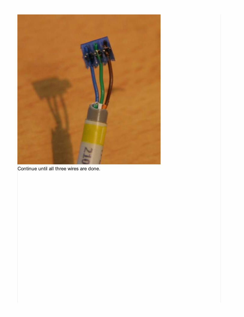
Continue until all three wires are done.
5 of 11 10/26/2012 1:00 AM
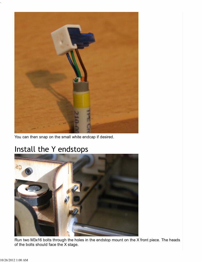
You can then snap on the small white endcap if desired.
Run two M3x16 bolts through the holes in the endstop mount on the X front piece. The headsof the bolts should face the X stage.
.
10/26/2012 1:00 AM
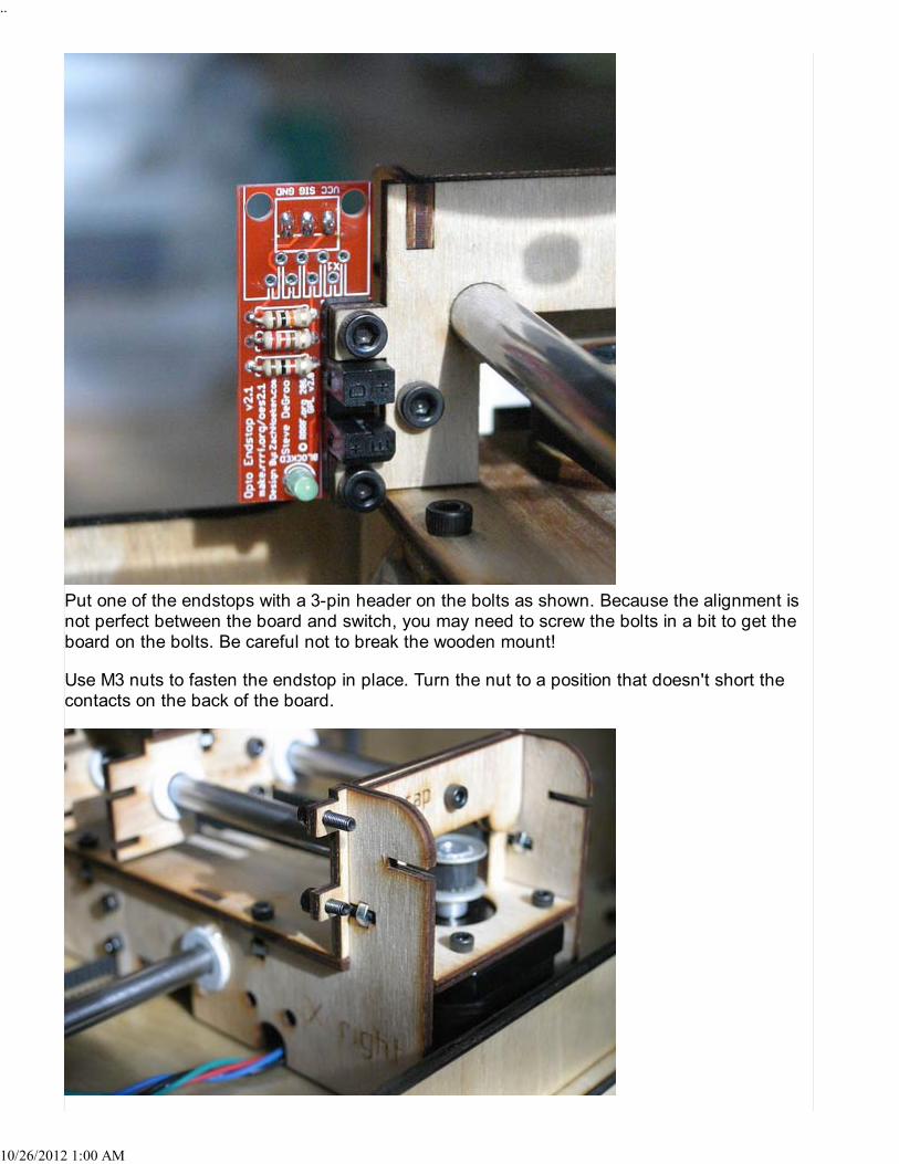
Put one of the endstops with a 3-pin header on the bolts as shown. Because the alignment isnot perfect between the board and switch, you may need to screw the bolts in a bit to get theboard on the bolts. Be careful not to break the wooden mount!
Use M3 nuts to fasten the endstop in place. Turn the nut to a position that doesn't short thecontacts on the back of the board.
..
10/26/2012 1:00 AM
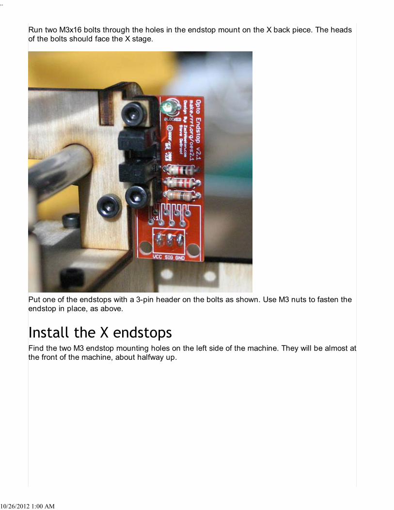
Run two M3x16 bolts through the holes in the endstop mount on the X back piece. The headsof the bolts should face the X stage.
Put one of the endstops with a 3-pin header on the bolts as shown. Use M3 nuts to fasten theendstop in place, as above.
Find the two M3 endstop mounting holes on the left side of the machine. They will be almost atthe front of the machine, about halfway up.
..
10/26/2012 1:00 AM

Use two M3 bolts to mount an endstop on the inside of the Cupcake CNC, as shown. Use M3nuts to fasten.
Find the two M3 endstop mounting holes on the right side of the machine. They will be almostat the front of the machine, about halfway up.
Use two M3 bolts to mount an endstop on the inside of the Cupcake CNC, as shown. Use M3nuts to fasten.
The Z endstops are both installed on the right side of the machine. The mounting holes areindicated in the picture.
Mount the top endstop on the inside of the machine, in the position shown.
9 of 11 10/26/2012 1:00 AM

Mount the bottom endstop on the inside of the machine, in the position shown.
This picture shows all the endstops on the right side of the makerbot.
10 of 11 10/26/2012 1:00 AM

Endstop triggers can be constructed of any long, reasonably thin, opaque object. Popsiclesticks (craft sticks) are popular choices. You can cut rectangles of thick card, as well. Paintyour triggers matte black to make them a bit more reliable.
To install an endstop trigger, first move a stage almost all the way to one end of its travel. Thenplace the stick in the slot in such a way that it protrudes all the way into the appropriateendstop. Once it is in place, use a drop of hot glue or rubber cement to keep it there.
The Y endstop triggers sit in the slots in the Y stage.
The X endstop triggers sit in the slots in the X stage.
There are no slots for the endstop triggers in the Z stage platform, so you'll need to improvise.A little bit of hot glue should hold them in place nicely.
11 of 11 10/26/2012 1:00 AM

Instructions for updating the Cupcake's Motherboard firmware.
This page describes how to update the Cupcake CNC's motherboard firmware. If you are usinga preassembled board or updating a board that you already have firmware installed on, youshould follow these instructions. However, if you've soldered your board together from a kit andare installing firmware for the first time, you will need to install the Arduino bootloader, asdescribed here.
We now recommend installing pre-built firmware images from ReplicatorG.
Download the latest version of ReplicatorG from the website. Older versions of ReplicatorGinclude the firmware in the download; later versions will automatically update their firmwarefrom the internet.
Make sure the motherboard is plugged into an ATX power supply.If there is an SD card in the SD slot, remove it before starting.Connect the Cupcake Motherboard to your computer with the USB to serial cable.
Start ReplicatorG.
.
10/26/2012 1:04 AM

Select "Machines > Update Firmware…" from the menu.
Select the board and version you're updating.
Select the version of the firmware you'd like to upload. This should ordinarily be the latestversion.
2 of 4 10/26/2012 1:04 AM

Select the serial port your USB-serial cable is hooked up to. The names will vary fromplatform to platform.
Read the instructions! You must manually push the reset button on the board at thesame time as you click the "Upload" button.Be patient! It ordinarily take a minute or two to upload new firmware. You should see amessage confirming success when it's done.
After you have upgraded your firmware, it might be a good idea to double check your FirmwarePreferences.
If you're having trouble uploading, here's some things to try:
Make sure that the motherboard is hooked up to a power supply— it can't program itselfwithout power.

Instructions for updating the Cupcake's plastruder firmware.
This page describes how to update the Cupcake CNC's plastruder firmware. If you are using apreassembled board or updating a board that you already have firmware installed on, youshould follow these instructions. However, if you've soldered your board together from a kit andare installing firmware for the first time, you will need to install an Arduino bootloader, asdescribed here.
We now recommend installing pre-built firmware images from ReplicatorG.
Download the latest version of ReplicatorG from the website. Older versions of ReplicatorGinclude the firmware in the download; later versions will automatically update their firmwarefrom the internet.
The firmware cannot be updated via the motherboard at this time. Here are the hardwarepreparation steps required to perform the update.
Using one of the CAT5 ethernet-style cables, plug the extruder board into one of themotherboard's four RS485 jacks.Make sure that the motherboard is plugged into an ATX power supply.Turn on the ATX power supply.Turn on the motherboard power switch
Connect your USB2TTL cable into the extruder board's six-pin serial header, next to thereset button
1 of 4 10/26/2012 1:07 AM

Make sure the colors indicated on the board match up with the colors on the cable!
There is a 7805 voltage regulator on the extruder board that supplies the 5VDC neededto power the logic.If your USB2TTL cable supplies 5VDC you may not need to have the extruder pluggedinto the motherboard to update firmware.
Start ReplicatorG.
Select "Machines > Update Firmware…" from the menu.
Select the board and version you're updating.
2 of 4 10/26/2012 1:07 AM

Select the version of the firmware you'd like to upload. This should ordinarily be the latestversion.
Select the serial port your USB-serial cable is hooked up to. The names will vary fromplatform to platform.
Click on the upload buton. Be patient; it will usually take a minute or two to upload thefirmware.
Note that in earlier versions of ReplicatorG, you needed to manually reset the
3 of 4 10/26/2012 1:07 AM

extruder board; this is no longer the case.TC - some users when updating from 1.6 to 1.8 of the extruder firmware had tomanually reset the board which requires clicking the reset button on the board justafter clicking the upload button. This can take many attempts (someone took 8) toget the timing right.
Be patient; it may take a minute or two to upload the firmware. When you're done, youshould see a message indicating success.
After you have upgraded your firmware, it might be a good idea to double check your FirmwarePreferences.
If you're having trouble uploading, here's some things to try:
Make sure that the motherboard is hooked up to a power supply— it can't program itselfwithout power.Make sure the extruder board is connected to the motherboard through a patch cable.
4 of 4 10/26/2012 1:07 AM

MakerBot Hotness is controlled heating of the build surface of the MakerBot CupCake CNC tominimize warping, improve 3D printing, enable larger object builds, and provide a host ofassorted other goodies such as raft-free printing, easy object release from temperatureresponsive surfaces such as glass, …
warping… raft-badness…
Lots of people and groups are working on their own versions and designs. Hive76, PleasantSoftware, MakerGear, AllArtBurns…
The heated build platform can be constructed from a number of parts:
the build surface, either the stock surface supplied with the cupcake or a replacementthe build platform, which holds the build surface to the Y stagea heater element, either on the build platform or between the build platform and the buildsurfacea temperature sensora controller (either passive or active) to power the heater element and maintain thetemperaturepossible software changes to set the temperature
MakerBot Cupcake Heated Build Platform v2.0
Build details are available on the wiki here as well as on Thingiverse
—ONLY POST YOUR MOST CURRENT OR BEST DESIGNS HERE, but feel free to link to ahistory of your designs on a different wiki page if you like —
this is the first heated build stage design that started them all, designed through collaborationwith the University of Pennsylvania.http://www.hive76.org/handling-hot-build-surfaces
1 of 3 10/26/2012 1:09 AM

Inspired by the success of the Hive76 design, I built this heated platform out of a 6mmaluminum plate, heated by 3x2.2Ω power resistors. The aluminum takes care of a uniform andstable heat distribution.The design was the first driven and controlled by the Extruder Controller board (so no extracontroller or power source needed).The whole thing is documented in my blog:
Canned Heat (Overall design)Living in times of warp-free printing Firmware changesHow to connect the 2nd thermistor?Raftless (A Skeinforge tool, that helps printing objects without raft)
Meanwhile, the firmware changes for the second temperature zone are part of the officialfirmware. So you you can just get the most recent version of the extruder firmware (andReplicatorG) from the MakerBot GitHub archives.
Please note, that the Raftless tool requires the newer version of Skeinforge ("created at2009-11-06"). This version is available as part of the ReplicatorG archive. It doesn't work withthe "official 0006 release"!
ssd2 (01/14/10):Alternatively, you can eliminate the raft by setting the number of Base and Interface layers inthe raft to zero, while still allowing the raft module to center the part and bring it to the buildplatform level.
zaggo (01/16/10):The Raftless script not only switches off the raft, but let you slow down the printing of the 1stlayer's perimeter loops. This helps a lot when printing complex (i.e. not rectangular) shapeswithout a raft.
Similar to Pleasant Warmth, use kapton tape to attach 30cm of nichrome (enough to make6-10 ohms, same as the extruder heater element) along with the thermistor to the bottom of aplate of aluminum, and heat and control it with the extruder using upgraded firmware. Use thebuild surface supplied with your machine or replace it with a glass or ceramic surface if you areusing PLA.
Note that some care must be taken that:
The nichrome wire doesn't directly touch wood where it could get hotThe thermistor is not crushed between the platform and the Y stageThe thermistor is in contact with the build platform and getting good readings (so youdon't end up with thermal run-away), and is not ripped lose by the weight of its ownwires.the wiring is carefully routed to not get tangled in the Y stage, or any of the stage motorsor pull on the platform while it moves
It would also be nice if there was a modular plug for the wiring near the platform or mounted toit.
Connect the thermistor to the three-pin header on the Extruder Controller 2.2 board marked
2 of 3 10/26/2012 1:09 AM
"A6". The pin at the top, nearest the A6 label, is Ground. The middle pin is VCC (+5V). Thebottom pin is Signal (connected to the A6 analog input of the processor). Connect thethermistor between Signal and Ground. Connect a 4.7KΩ resistor (color code Yellow-Purple-Red) between VCC and Signal. Connect a 10µF capacitor across the thermistor (fromSignal to Ground). Make sure that the + side of the capacitor is connected to Signal and the -side is connected to Ground.
Note: The description of the Extruder Controller V2.2 board says that the top pin ("nearest thelabel A6") is Signal but the circuit board traces show that the top pin is Ground and the bottompin is Signal.
This is the second design to be sold in the MakerBot store.
Build details are available on the wiki here as well as on Thingiverse
The design utilizes traces on the PC board to generate heat and an aluminum plate withassistance from thermal paste to create a heated build surface.
The red LEDs are not required, but provide an opportunity to practice your soldering skills.
This design is available on Thingiverse with build details on his Nats Nonsense blog.
This design depends on readily available parts (except perhaps for the Copper Clad FR4).
The two things you need are heat and control. Control is very important (no fires please!), andis generally accomplished with a thermistor or temperature sensing element for feedback. Butthere's a lot of room for creativity, you could get very crafty here… PTC heaters, hair dryers, …are all valid designs and some have even been successfully used in the field as reported onthe makerbot operators listserv.
RepRap solution for heated bed
3 of 3 10/26/2012 1:09 AM
If you feel like you are missing a component- DON'T PANIC!
Many MakerBot products have a series of subkits- an item may not be immediately visible.Some items look very similar, and can be challenging to see the differences. Take a deepbreath, make sure you have adequate light to handle small components, and slowly examinethe component bags and parts. Check out the floor too, or under your keyboard.
Some commonly missed parts:
*Gold Magnets- In the CupCake CNC Ultimate Kit the gold magnets ship in two locations. 5gold magnets ship inside the "Build Surface Kit" and 10 Gold magnets ship packed awayinside the "Hardware Burrito." Since they are magnetic, sometimes they are hidden underneathother metal components.
*Z-Motor Pulley or X-Idler Pulley- These two pulleys are the same in every way but one- Thebore hole of the Z-Motor pulley is a tiny bit smaller than the X-Idler Pulley bore hole. It ispossible to use the X-Idler pulley on the Z-Motor shaft, but then the X-Idler bolt won't fit in theremaining brass pulley. Just swap them and you're back in shape. If you still have a bit oftrouble fitting the Z-Motor pulley, you can sand inside the brass bore until it fits on more easily.There should never be any need to "drill out" a pulley to make items fit.
*MK5 Thermal Cape- In some documentation photos the cape is mirrored mylar, but in latershipments it is made from clear mylar. It can be easy to miss as it is a clear plastic objectinside a clear zip-lock bag, with the other custom bits kit for the MK5.
*Opto-Endstops- The CupCake Ultimate and Starter don't come standard with endstops. TheOpto-Endstops have some trouble under certain fluorescent light bulbs, so we discontinuedshipping them in the early days of shipping CupCake CNCs. The Thing-O-Matic will shipstandard with mechanical endstops. Optical and Mechanical endstops will be available forpurchase under electronics in the store.
*Bearings- The 608 skate bearings that come with the CupCake are shipped inside a smallstorage tube. Sometimes the tube is clear, sometimes the tube is black. When the tube isblack it can be unclear what the tube is for, but just crack it open- it's full of bearings.
*Relay Board Kit- With the CupCake CNC Ultimate Kit the "Relay Board Kit" ships inside theAutomated Build Platform box. It's a white box identical to the box that the MK5 Plastrudercomes in.
If you find and can determine that an item is definitely missing that you should have received-please send us an email describing the situation. You can contact us here:
1 of 1 10/26/2012 1:15 AM

10/26/12 11:11 AM
Board Positions
So much stuff!The Cupcake Ultimate has several upgrades that didn't exist when we originally designed the Cupcake. Because ofthis, you need to do a bit of jockeying to get all of your boards nicely mounted on the machine. Here's a quick guide toa recommended setup.
This image is of a bot in the wild, from Lucas & Kent Weakley of Blue Sky Graphic Communciation.
So what do we see here? The extruder board is mounted above the motherboard. The motherboard has been left un-flipped for maximum wiring neatness — note that it will be hard to get that SD card out in that position. Our steppermotors are in their original positions, but the top one has the relay board mounted on top of it using the relay boardmount kit.
Of course, this is only one way to get it done — some folks mount their boards in other places. Feel tree to try othersetups if you like. The only place we don't recommend is mounted to the top of the machine, because all the heat fromthe build platform and extruder might just fry your board.
Pro tip: The wire organization is amazing on this bot, but that SD card is going to be tough to get to. It might be easierif the user added extra spacers to the motherboard, to raise it above the extruder controller, or if they just left thebottom-left spacer & screw off the extruder controller. Other than that, though…it's hard to find fault with this setup.