cti tp10-09
DESCRIPTION
cooling technology institute tech. paperTRANSCRIPT

COOLING TECHNOLOGY INSTITUTE
PAPER NO: TP10-09
CATEGORY: ENVIRONMENTAL IMPACT
PLUME ABATEMENT –THE NEXT GENERATION
The studies and conclusions reported in this paper are the results of the author’s own work. CTI has not investigated, and CTI expressly dis-claims any duty to investigate, any product, service process, procedure, design, or the like that may be described herein. The appearance of any technical data, editorial material, or advertisement in this publication does not constitute endorsement, warranty, or guarantee by CTI of any product, service process, procedure, design, or the like. CTI does not warranty that the information in this publication is free of errors, and CTI does not necessarily agree with any statement or opinion in this publication. The user assumes the entire risk of the use of any information in this publication. Copyright 2010. All rights reserved.
Presented at the 2010 Cooling Technology Institute Annual ConferenceHouston, Texas - February 7-11, 2010
PAUL LINDAHLKEN MORTENSEN
SPX COOLING TECHNOLOGIES

Abstract
Cooling towers have been modified to reduce the visibility of their effluent water vapor plumes for about 40 years. The evolution, breadth of experience and technologies of plume abatement cooling towers will be described. An evolutionary improvement to existing plume abatement designs using a different heat transfer approach will be described, including some of the development and demon-stration achievements to date. Differences from currently used coil-type wet/dry tower designs and benefits of the improved technology for cooling tower applications will be presented.
Introduction
The earliest designs for reduction of visibility due to con-densation of water vapor plumes from cooling towers were in the 1960’s. The applications were wet/dry or other heat sources in a series path, and were industrial or air-con-ditioning applications. The applications were considered safety related. In the 1970’s, designs evolved which were based on parallel path wet/dry technology. For almost 40 years parallel path wet/dry, or hybrid, technologies have been applied to reduce visible plume from cooling towers. A significant level of operating experience in various con-figurations and application types, in response to various end user needs, has developed over that period of time. A new technology has emerged which is series path, but does not use dry type exchangers. Instead, the technol-ogy uses air to air instead of water to air heat exchange. This technology has been developed, demonstrated and emerges as an attractive option for plume abatement in the new century. The new condensing module technology is based on a natural process with value in terms of energy benefits, piping cost, low maintenance and low complexity.
About Cooling Tower Plumes
The air leaving a cooling tower is essentially saturated, e.g. 100% relative humidity, and when discharging into cold, humid ambient air some of the moisture condenses. This condensate becomes visible if enough is present and looks like clouds or ground fog. The tendency for visibility is well correlated to whether human breath would be vis-ible when exhaled. When it is warm and dry, your breath is not visible. The colder and more humid it is, the more visible your breath becomes.
Why does the visibility of the plume matter? There are four main reasons; aesthetics, community relations, regulatory requirements and safety. Aesthetics is simply the percep-tion that the effluent from a tower obscures visibility of whatever is on the other side of the plume, and may be undesirable. Community relations involves the associa-tion of the cloud-like water vapor and condensate effluent from a cooling tower on a cold day with smoke leaving an industrial process stack. A plant with a cooling tower may
be perceived as emitting smoke. Regulatory requirements relate to aesthetics and community relations, but are trans-lated into public policy that requires use of plume-free, or limited plume technology. Safety typically relates to the potential that a visible plume from a cooling tower might obstruct a roadway, or for an airport application, the view from the control tower. Sometimes, concerns about icing from plumes contacting cold roadway or other surfaces also come into play. This is not directly related to visibility of the plume. Any time there is moisture in the air, whether in clouds or ground fog or a plume (visible or not), there is a potential for this moisture to condense and freeze on cold surfaces.
Series Path History
It was recognized in the mid-1960’s that if the humidity leaving the tower could be reduced, the plume would be less visible or visible for fewer hours per year. The earliest designs involved adding heat sources to the air leaving the cooling tower or “wet” section, to reduce the relative humidity of the leaving air by heating it up. Two basic ap-proaches were considered. One was to add a finned tube, or more commonly, a bare tube heat exchanger above (or downstream of) the eliminators to heat all of the wet section discharge air. The other was to add heat to the air using burners above the fans (induced draft with propeller-type fans at the tower discharge). The heat exchanger designs either used all or part of the hot water going to the tower, or used an external heat source, such as steam from some other available process, to provide the heating effect. The burner design was applied at an airport in a concrete tower with concrete fan cylinder, and burned a combustible gas, but the plume control was not found to be necessary and the burner system is believed to have been decommissioned in the 1970’s.
Series path wet/dry (SPWD) towers, with metallic coils above (or downstream) of the eliminators required pre-mium corrosion resistant materials due to the hot moist environment in the tower plenum. Over a period of time close-spaced fins would tend to clog in this environment. Thus the designs typically had what are called “low fins” that are wide spaced and short fin height, or had no fins at all, “bare tube”, particularly with higher temperature steam. The drawbacks to these designs were full time pressure drop for the cooling tower fan, and high pump head for hot water coils. The positive was that the entire volume of wet section air was heated in the coils, so the discharge air was well mixed. External heat source designs with steam, in effect, would be trying to control two processes with one fan, and would have some control complexity as well as a need to insulate the piping to and from the tower in cold climates.
1

Parallel Path Wet/Dry (PPWD) Towers
Most of the history of wet/dry towers evolved after the development of the basic parallel path tower designs and patents around 1970. This concept involved adding dry sections, using finned tube heat exchangers, above the wet sections, but different from the SPWD’s just described, the air was drawn by the induced draft fans in parallel through the dry sections and wet sections, mixed in the plenum, and discharged from the fan at a reduced relative humidity. The air leaving the dry sections is heated without adding moisture, so is hot and has low humidity. The air leaving the wet sections is essentially at 100% hu-midity (saturated) warm air. The mixed air leaving the tower is at a reduced relative humidity. If the humidity is reduced via a proper balance of dry and wet section performance capability, the air that leaves the tower will not become super-saturated (condensed drops, or visible plume) as it mixes with ambient air, see Figure 1.
Figure 1. Parallel Path Wet/Dry Tower cross section
Parallel path designs had the advantage of being able to add face dampers on the dry sections that would shut off most of the air flow, enabling nearly full wet cooling tower performance in the summer time at near to wet tower fan power. Dampers typically leak some air, and in addition, some dry section performance may be desired for morning and evening conditions even in the summer, so PPWD towers typically are higher fan power than wet only towers. The selection of PPWD towers for plume abatement is generally against a summer thermal design point and a winter plume design point. Figure 2 shows ambient weather points divided by the saturation curve, to the left of which are super-saturated air, or visible
fogging conditions. To the right of the saturation curve are sub-saturated, or non-visible conditions. If one looks at a visual map of the distribution of ambient points for a given location, the map would look like the gold band across the chart. For a typical wet-only cooling tower, the curve toward the right of the chart is the fogging frequency curve for design flow and cooling range, which divides the weather points into conditions for which the tower would produce visible plume to the left, and those which would not to the right. A substantial percentage of the ambient points are in the visible plume zone for this example case. The fogging frequency for the un-abated tower is about 60%. The fogging frequency curve for a plume abatement tower selected for approximately 10% of the hours per year of visible plume is shown toward the left of the chart. This would allow visible plume at the coldest and most humid hours of the year, typically in early mornings, before dawn. The plume abatement design point would be the point (Wet Bulb & Dry Bulb Temperatures) where the fogging frequency curve crosses the uppermost edge of the weather data band for a location.
Figure 2. Plume Abatement Design Point Determination
PPWD towers also generally use hot water passing first through the dry section, then through the wet section to get maximum dry performance. This involves additional pumping head to move water both through the coils and above the wet section. Since a risk of freezing the metal coils exists if water is left standing in the coils or if water distribution is not even enough, substantial design effort has gone into hydraulic design and controls to protect the dry sections. Some manufacturers also utilize vacuum pumps to assure that air does not become trapped in por-tions of the coil system, potentially also trapping water that could freeze. Note also, that PPWD towers involve mixing of low velocity streams of air that do not generate sufficient turbulence for complete mixing across the plan area of the tower plenum. Mixing devices have commonly been used, particularly for counterflow designs, to gain sufficient mix-ing of the dry and wet streams to prevent unmixed wet air from discharging from the tower visibly.
Air Flow
Plenum
Air Flow
Air Flow Air Flow
Spray NozzlesEliminators
Dry Section Coil
Hot Water Inlet Hot Water Inlet
Air Flow
Wet SectionDRY BULB TEMPERATURE
PLUME DESIGNPOINT
PLUME FREQUENCYCURVE FOR PLUME
ABATEMENT TOWER
VISIBLE PLUME AREA
STANDARDEVAPORATIVETOWER
MOI
STUR
E CO
NTEN
T
SATU
RATIO
N CU
RVE
BAND OF ANNUALTEMPERATUREOCCURANCES
2
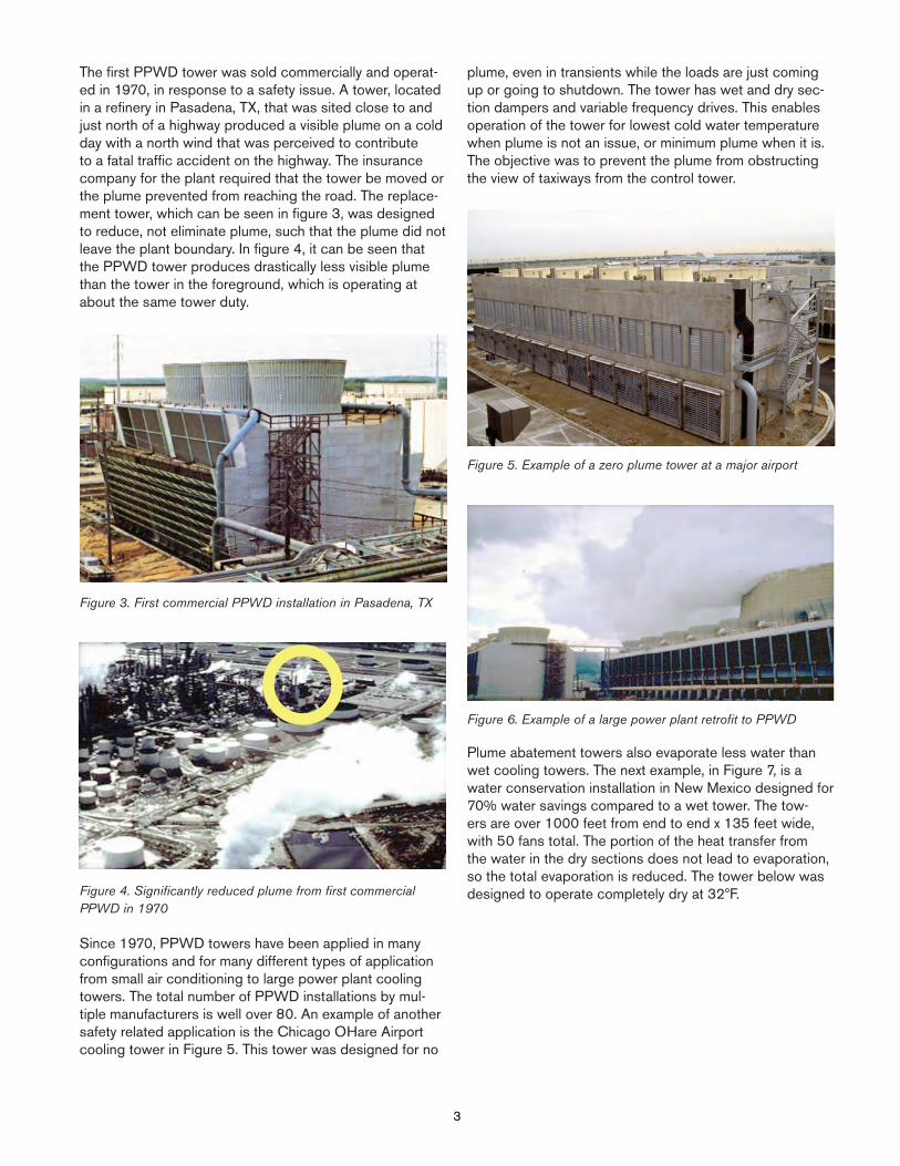
The first PPWD tower was sold commercially and operat-ed in 1970, in response to a safety issue. A tower, located in a refinery in Pasadena, TX, that was sited close to and just north of a highway produced a visible plume on a cold day with a north wind that was perceived to contribute to a fatal traffic accident on the highway. The insurance company for the plant required that the tower be moved or the plume prevented from reaching the road. The replace-ment tower, which can be seen in figure 3, was designed to reduce, not eliminate plume, such that the plume did not leave the plant boundary. In figure 4, it can be seen that the PPWD tower produces drastically less visible plume than the tower in the foreground, which is operating at about the same tower duty.
Figure 3. First commercial PPWD installation in Pasadena, TX
Figure 4. Significantly reduced plume from first commercial PPWD in 1970
Since 1970, PPWD towers have been applied in many configurations and for many different types of application from small air conditioning to large power plant cooling towers. The total number of PPWD installations by mul-tiple manufacturers is well over 80. An example of another safety related application is the Chicago OHare Airport cooling tower in Figure 5. This tower was designed for no
plume, even in transients while the loads are just coming up or going to shutdown. The tower has wet and dry sec-tion dampers and variable frequency drives. This enables operation of the tower for lowest cold water temperature when plume is not an issue, or minimum plume when it is. The objective was to prevent the plume from obstructing the view of taxiways from the control tower.
Figure 5. Example of a zero plume tower at a major airport
Figure 6. Example of a large power plant retrofit to PPWD
Plume abatement towers also evaporate less water than wet cooling towers. The next example, in Figure 7, is a water conservation installation in New Mexico designed for 70% water savings compared to a wet tower. The tow-ers are over 1000 feet from end to end x 135 feet wide, with 50 fans total. The portion of the heat transfer from the water in the dry sections does not lead to evaporation, so the total evaporation is reduced. The tower below was designed to operate completely dry at 32ºF.
3
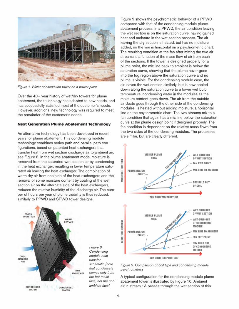
Figure 7. Water conservation tower on a power plant
Over the 40+ year history of wet/dry towers for plume abatement, the technology has adapted to new needs, and has successfully satisfied most of the customer’s needs. However, additional new technology was required to meet the remainder of the customer’s needs.
Next Generation Plume Abatement Technology
An alternative technology has been developed in recent years for plume abatement. This condensing module technology combines series path and parallel path con-figurations, based on patented heat exchangers that transfer heat from wet section discharge air to ambient air, see Figure 8. In the plume abatement mode, moisture is removed from the saturated wet section air by condensing in the heat exchanger, resulting in lower temperature satu-rated air leaving the heat exchanger. The combination of warm dry air from one side of the heat exchangers and the removal of some moisture content by cooling of the wet section air on the alternate side of the heat exchangers, reduces the relative humidity of the discharge air. The num-ber of hours per year of plume visibility is thus reduced, similarly to PPWD and SPWD tower designs.
Figure 8. Condensing module heat transfer schematic [note that condensate comes only from the hot moist face, not the cool ambient face]
Figure 9 shows the psychrometric behavior of a PPWD compared with that of the condensing module plume abatement process. In a PPWD, the air condition leaving the wet section is on the saturation curve, having gained heat and moisture in the wet section process. The air leaving the dry section is heated, but has no moisture added, so the line is horizontal on a psychrometric chart. The resulting condition at the fan after mixing the two air streams is a function of the mass flow of air from each of the sections. If the tower is designed properly for a plume point, the mix line back to ambient is below the saturation curve, showing that the plume never goes into the fog region above the saturation curve and no plume is visible. For the condensing module case, the air leaves the wet section similarly, but is now cooled down along the saturation curve to a lower wet bulb temperature, condensing water in the modules as the moisture content goes down. The air from the outside air ducts goes through the other side of the condensing modules, is heated without adding moisture, a horizontal line on the psychrometric chart. The two streams mix to a fan condition that again has a mix line below the saturation curve at the plume design point if designed properly. The fan condition is dependent on the relative mass flows from the two sides of the condensing modules. The processes are similar, but are clearly different.
Figure 9. Comparison of coil type and condensing module psychrometrics
A typical configuration for the condensing module plume abatement tower is illustrated by Figure 10. Ambient air in stream 1A passes through the wet section of this
DRY BULB TEMPERATURE
PLUME DESIGNPOINT
VISIBLE PLUME AREA
WET-BULB OUTOF WET SECTION
MOI
STUR
E CO
NTEN
T
SATU
RATIO
N CU
RVE
DRY-BULB OUTOF COIL
FAN EXIT POINT
MIX LINE TO AMBIENT
DRY BULB TEMPERATURE
WET-BULB OUTOF WET SECTION
MOI
STUR
E CO
NTEN
T
SATU
RATIO
N CU
RVE
WET-BULB OUTOF CONDENSINGMODULE
DRY-BULB OUTOF CONDENSINGMODULE
MIX LINE TO AMBIENT
FAN EXIT POINT
PLUME DESIGNPOINT
VISIBLE PLUME AREA
4

counterflow tower. The warm, saturated air from the wet section, stream 1B, passes up through one side of the crossflow heat exchanger modules which are oriented in a diamond pattern, leaving at a cooler, but still saturated, condition. Ambient air also passes into the tower via ducts, stream 2A, and into the alternate side of the heat exchanger modules, leaving warmer and with lower rela-tive humidity, stream 2B. Streams 1B and 2B mix in the plenum above the modules, stream 3, leaving the tower as reduced humidity air, stream 4. Proper proportions and air flow through the wet section and the condensing mod-ules result in the targeted plume abatement design point. The flow of air through the modules can be dampered to maximize the wet section air flow in the summer. In addi-tion, the ducts supplying air to the modules can be vented to enable wet section air to pass through both sides of the modules, increasing wet section air flow still more. Note that the airflow from the condensing modules is well dis-tributed across the plan area, resulting in effective mixing of the two air streams without a need for mixing devices.
Figure 10. Schematic cross section of the tower and condens-ing module design for plume abatement
The condensing modules are based on technology backed, in part, by grants from the U.S. Department of En-ergy (DOE) via the National Energy Technology Laboratory (NETL) The grants from the DOE were part of the Innova-tion for Existing Power Plants program as an improvement over traditional PPWD technology.
In addition to extensive test cell and prototype work at our Research and Development center, and CFD simulation of designs, a full scale demonstration project was installed at a power plant in New Mexico. Note CFD modeling examples in Figure 11, illustrating temperature and velocity distributions in the demonstration tower configuration.
Figure 11. Illustration of CFD modeling of the demonstration installation, temperature on the left and velocity on the right
The demonstration installation is in a base-loaded coal-fired power plant that operates 24/7. An end-cell of the original tower was demolished, and a new demonstration cell installed. The demonstration installation was complet-ed in 2007 and has operated successfully for more than a year. Figure 12 shows two photographs of the tower, taken on different dates, both operating at 27ºF dry bulb, with one having 60% humidity and the other 65% humidity, without visible plume, on either date, in comparison to the substantial plume coming from the rest of the tower.
Figures 13, 14 and 15 show the factory assembled mod-ules being hoisted up into the tower, and the configuration when all are in place. Figure 16 shows the windows in the side casing where ambient air enters the ducts that feed the dry side of the modules. The configuration shown was designed for high water conservation capability for this high desert location. The condensing module configuration is an evolution for plume abatement purposes, but also ac-complishes significant water savings.
Figure 12. Operation of the demonstration cell, side view [Date 1/21/09 Temperature 27°F Relative Humidity 65%, photo by Ken Mortensen, end view [Date 3/11/08 Temperature 27°F Relative Humidity 60%, photo by Tom Ruisinger]
3
4 4
33
1 1
2
5
6 6
5
2
5

Figure 13. Hoisting of factory assembled condensing modules [photo by Dennis Parker]
Figure 14. Tower under construction, showing position of modules [photo by Dennis Parker]
Figure 15. Condensing modules positioned in demonstration cell [photo by Dennis Parker]
Figure 16. Windows in casing for air supply ducts to modules [photo by Tom Ruisinger]
This water conservation/plume abatement cooling tower has operated over two winters, without issues during cold weather operation. Since there is no circulating water in the modules, and condensation can only happen with warmed wet effluent air in direct contact with the conden-sate flowing downward in counter-current flow, the risk of any freezing is very low. Figure 17 shows the demonstra-tion tower operating in winter conditions, 35°F dry bulb and 50% relative humidity.
Figure 17. Cold operation of the demonstration cell [Date 2/09/09 Temperature 35°F Relative Humidity 50%, photo by Jared Hickman]
The demonstration project accomplished measured water savings of about 18% and virtually non-existant plume ac-cording to the owner’s public statements.
6

Why condensing modules?
The PPWD designs have been successful for many years, however, there were unmet needs for which improvements could be made. These improvements have come in the areas of design flexibility, reduced associated non-tower installation costs incurred by the EPC/owner and reduced operating costs and complexity at competitive tower cost with the new condensing module technology. Overall, a significant benefit may result for the end user and the Engineer/Procure/Construct (EPC) contractor. The envi-ronmental benefit of this technology parallels the benefits of a PPWD, with the added benefits of having a very low drift rate and of replacing a portion of the lower quality tower make-up water quantity by the near condensate quality water recovered from air leaving the wet section. The net make-up water requirement is reduced both by the water quantity returned and by the higher quality returned which enables operation at fixed cycles of concentration with less blowdown and make-up. Figure 18 shows the greatly reduced dissolved solids content in the conden-sate recovered in the modules. The water produced by the modules can be returned to the tower basin, or can alternatively be substantially extracted for use in other plant applications. The percentage of water saved on an annual basis will vary with the difficulty of the plume point and the weather at a location, but may be expected in the 3-15% range for proportions of condensing module to wet section typical of plume abatement applications. The demonstration project referenced above was designed for greater water savings. The small amount of solids content shown in Figure 18 is a result of drift being captured in the condensing modules. There is direct impingement on the module surfaces, as well as the drift drops being the nucleation sites for condensation to form as the air is cooled below the dew point in the condensing modules. Since the water would otherwise be pure condensate, note that the capture of some drift is validated by the detection of circulating water chemicals at low levels in the recovered condensate stream, as there is no other mechanism for the circulating water chemicals to end up in the condensate. Resulting drift rates leaving the tower are likely to be very difficult to measure, as the rates leaving the eliminators can be less than 0.0005% of circulating water. Measurements are planned. Low drift rate translates to lower calculated PM10 emissions for the plant. US EPA requirements include cooling tower drift as a particu-late emission by calculation from the drift rate and water composition. This is an environmentally beneficial resource recovery technology.
Figure 18. Condensate quality and drift reduction
Design flexibility is improved via the potential for back-to-back plume abatement towers for constricted plant sites. The back-to-back configuration combines two lines of cooling tower cells into one tower, with a common wall down the centerline of the “dual row” tower, potentially fitting the tower onto sites where two towers would not fit. This has not been practical for PPWD towers due to the difficulty of getting adequate dry section air to the center-line of the tower. The new technology requires ducting of ambient air to feed the condensing modules which cover the entire tower plan area. Thus, the ducts can be sized to carry air to the centerline of a back-to-back tower as well. As more attention is focused on larger nuclear, coal with carbon capture and integrated gasification combined cycle power plants, the need to compress the tower footprint becomes more important. Flexibility and cost in foundation design is also improved by way of the even distribution of weight in the condensing module tower, rather than having concentrated weight on the perimeter columns to support the metal coils (and often face dampers) of a PPWD. This is likely to be more significant for a retrofit of an existing tower to plume abatement, as the existing tower foundations would not have been designed for the coil plus damper loads on the side columns. Specialized cold water basin and foundation designs may sometimes be avoided. Foundation loads and costs are highly site specific, influenced by wind loads and soil conditions as well as the dead and operating loads of the tower. Figure 19 visualizes a simple comparison.
Figure 19. Comparison of load distribution
CondensatesCo en ata
7
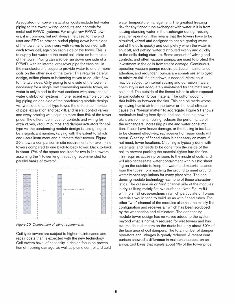
Associated non-tower installation costs include hot water piping to the tower, wiring, conduits and controls for metal coil PPWD systems. For single row PPWD tow-ers, it is common, but not always the case, for the end user and EPC to provide buried piping down both sides of the tower, and also risers with valves to connect with each tower cell, again on each side of the tower. This is to supply hot water to the metal coil inlets on both sides of the tower. Piping can also be run down one side of a PPWD, with an internal crossover pipe for each cell in the manufacturer’s scope to provide water to one or more coils on the other side of the tower. This requires careful design, orifice plates or balancing valves to equalize flow to the two sides. Only piping to one side of the tower is necessary for a single row condensing module tower, as water is only piped to the wet sections with conventional water distribution systems. In one recent example compar-ing piping on one side of the condensing module design vs. two sides of a coil type tower, the difference in price of pipe, excavation and backfill, and risers, control valves and sway bracing was equal to more than 5% of the tower price. The difference in cost of controls and wiring for extra valves, vacuum pumps and damper actuators for coil type vs. the condensing module design is also going to be a significant number, varying with the extent to which end users instrument and automate their towers. Figure 20 shows a comparison in site requirements for two in-line towers compared to one back-to-back tower. Back-to-back is about 17% of the space required for two in-line towers, assuming the 1 tower length spacing recommended for parallel banks of towers1.
Figure 20. Comparison of siting requirements
Coil type towers are subject to higher maintenance and repair costs than is expected with the new technology. Coil towers have, of necessity, a design focus on preven-tion of freezing damage, as well as plume control and cold
water temperature management. The greatest freezing risk for any finned tube exchanger with water in it is from leaving standing water in the exchanger during freezing weather operation. This means that the towers have to be circuited, valved and designed to enable getting water out of the coils quickly and completely when the water is shut off, and getting water distributed evenly and quickly to the coils during start-up. Some amount of valving and controls, and often vacuum pumps, are used to protect the investment in the coils from freeze damage. Continuous operation vacuum pumps require particular maintenance attention, and redundant pumps are sometimes employed to minimize risk if a shutdown is needed. Metal coils may be subject to internal scaling and corrosion if water chemistry is not adequately maintained for the metallurgy selected. The outside of the finned tubes is often exposed to particulate or fibrous material (like cottonwood fluff) that builds up between the fins. This can be made worse by having humid air from the tower or the local climate cause this “foreign matter” to aggregate. Figure 21 shows particulate fouling from flyash and coal dust in a power plant environment. Fouling reduces the performance of the exchangers, increasing plume and water consump-tion. If coils have freeze damage, or the fouling is too bad to be cleaned effectively, replacement or repair costs will occur. Cleaning of finned tubes is necessary on many, if not most, tower locations. Cleaning is typically done with water jets, and needs to be done from the inside of the coil to prevent packing the material tighter into the fins. This requires access provisions to the inside of coils, and will also necessitate water containment with plastic sheet-ing on the outside to keep the water and material cleaned from the tubes from reaching the ground to meet ground water impact regulations for many plant sites. The con-densing module technology has none of these character-istics. The outside air or “dry” channel side of the modules is dry, utilizing mainly flat pvc surfaces (Note Figure 8.) with no small cross-sections in which particulate or fibrous materials would tend to build up as with finned tubes. The other “wet” channel of the modules also has the mainly flat configuration and receives air which has been scrubbed by the wet section and eliminators. The condensing module tower design has no valves added to the system beyond what is normally required for wet towers and has external face dampers on the ducts but, only about 60% of the face area of coil dampers. The total number of damper operators and linkages is greatly reduced. A recent com-parison showed a difference in maintenance cost on an annualized basis that equals about 1% of the tower price.
8

Figure 21. Fin fouling by particulate clumping
The largest operating costs for PPWD or condensing module towers are fan and pumping power. The condens-ing module tower has no pumping head above the level of the wet section, and thus has significantly lower pump head than a coil type tower. Pumps run nearly 24/7 in most cases. Because the condensing module design is a series air path, there is always pressure drop on the air side through the modules that the fans must overcome. Fans, however, don’t usually run full time. The comparison will vary on a case by case basis, but typically the lower pumping power of the condensing module tower tends to outweigh the fan power increase, sometimes significantly.
Conclusions
A robust history of PPWD application has resulted in significant application experience in solving plume abatement needs for end users in power and other industries. Customer needs for reduced operating and capital costs for plume abatement and the emerging need for large back-to-back plume abatement towers have driven the development of the condensing module technology. This technology satisfies many of the unmet needs of the end user, while also satisfying the regulatory, safety or neighbor driven plume abatement drivers. Value is added in the areas of design flexibility, reduced non-tower installation costs and reduced operating costs at competitive tower cost. Reduced water consumption is also accomplished, with the added poten-tial for extraction of a cleaner, higher quality water stream than enters the tower as make-up. The combination offers interesting potential for new and existing facilities.
References:
1. Cooling Tower Fundamentals, Second Edition, revised 2009, Ed. John Hensley et al., SPX Cooling Technologies, Overland Park, KS, 2009, pp 26-28.
9