ct4110, cts4110 - diycaravans.com.au · kets. we supply the industry and aftermarket with a...
TRANSCRIPT
Cassette toilet for recreational vehiclesInstallation manual . . . . . . . . . . . . . . .2
Toilettes à cassette pour véhicules de loisirsNotice de montage . . . . . . . . . . . . . .20
Inodoros de cassette para vehículos de tiempo libreInstrucciones de montaje . . . . . . . . .40
Sanitário de cassete para veículos de recreioInstruções de montagem . . . . . . . . .60
EN
FR
ES
PT
CT4110, CTS4110
2 EN
Dometic Group is a customer-driven, world-leading provider of leisure products for the RV, automotive, truck and marine mar-kets. We supply the industry and aftermarket with a complete range of air conditioners, refrigerators, awnings, cookers, sanita-tion systems, lighting, mobile power equipment, comfort and safety solutions, windows, doors and other equipment that makelife more comfortable away from home. Dometic Group supplies a wide range of workshop equipment for service and maintenance of built-in air conditioners. DometicGroup also provides specially designed refrigerators for hotel rooms, offices, wine storage and transport and storage of medi-cal products. Our products are sold in almost 100 countries and are produced mainly in wholly-owned production facilities around the world.
© Dometic GmbH - 2011-2015 - Subject to change without prior notice
Dometic GmbHIn der Steinwiese 16D-57074 Siegenwww.dometic.com
Dometic Corporation, Sanitation Division13128 SR 226, PO Box 38Big Prairie, OH 44611 USACustomer support: 1-800-321-9886 (USA and Canada)
330-439-5550 (International)
3EN
1.0 General . . . . . . . . . . . . . . . . . . . . . . . . . . . . . . . . . . . . . . . . . . . . . . . . .41.1 Guide to these installation instructions . . . . . . . . . . . . . . . . . . . . . . . . . . . . . . . . . . . . . . . . . . . . . . .41.2 Copyright protection . . . . . . . . . . . . . . . . . . . . . . . . . . . . . . . . . . . . . . . . . . . . . . . . . . . . . . . . . . . . .41.3 Explanation of symbols used in this manual . . . . . . . . . . . . . . . . . . . . . . . . . . . . . . . . . . . . . . . . . .41.4 Limitation of liability . . . . . . . . . . . . . . . . . . . . . . . . . . . . . . . . . . . . . . . . . . . . . . . . . . . . . . . . . . . . . .51.5 Warranty . . . . . . . . . . . . . . . . . . . . . . . . . . . . . . . . . . . . . . . . . . . . . . . . . . . . . . . . . . . . . . . . . . . . . .51.6 Environmental notices . . . . . . . . . . . . . . . . . . . . . . . . . . . . . . . . . . . . . . . . . . . . . . . . . . . . . . . . . . . .5
2.0 Safety instructions . . . . . . . . . . . . . . . . . . . . . . . . . . . . . . . . . . . . . . . .52.1 Intended use . . . . . . . . . . . . . . . . . . . . . . . . . . . . . . . . . . . . . . . . . . . . . . . . . . . . . . . . . . . . . . . . . . .52.2 Installation notes . . . . . . . . . . . . . . . . . . . . . . . . . . . . . . . . . . . . . . . . . . . . . . . . . . . . . . . . . . . . . . . .52.3 Standards and regulations . . . . . . . . . . . . . . . . . . . . . . . . . . . . . . . . . . . . . . . . . . . . . . . . . . . . . . . .5
3.0 Description of model . . . . . . . . . . . . . . . . . . . . . . . . . . . . . . . . . . . . . .63.1 Model identification . . . . . . . . . . . . . . . . . . . . . . . . . . . . . . . . . . . . . . . . . . . . . . . . . . . . . . . . . . . . . .63.2 Toilet identification label . . . . . . . . . . . . . . . . . . . . . . . . . . . . . . . . . . . . . . . . . . . . . . . . . . . . . . . . . .63.3 Technical data . . . . . . . . . . . . . . . . . . . . . . . . . . . . . . . . . . . . . . . . . . . . . . . . . . . . . . . . . . . . . . . . . .63.4 Explanation of components . . . . . . . . . . . . . . . . . . . . . . . . . . . . . . . . . . . . . . . . . . . . . . . . . . . . . . .7
4.0 Installing the toilet . . . . . . . . . . . . . . . . . . . . . . . . . . . . . . . . . . . . . . . .74.1 Installing the service door . . . . . . . . . . . . . . . . . . . . . . . . . . . . . . . . . . . . . . . . . . . . . . . . . . . . . . . . .74.2 Create wall apertures . . . . . . . . . . . . . . . . . . . . . . . . . . . . . . . . . . . . . . . . . . . . . . . . . . . . . . . . . . . .7
4.2.1 Wall aperture service door . . . . . . . . . . . . . . . . . . . . . . . . . . . . . . . . . . . . . . . . . . . . . . . . . . . . . . . . . . . . . . . . .74.3 Installing the toilet . . . . . . . . . . . . . . . . . . . . . . . . . . . . . . . . . . . . . . . . . . . . . . . . . . . . . . . . . . . . . . .8
4.3.1 Installing the CT 4110 toilet . . . . . . . . . . . . . . . . . . . . . . . . . . . . . . . . . . . . . . . . . . . . . . . . . . . . . . . . . . . . . . . .84.3.1.1 Fitting the CT 4110 toilet . . . . . . . . . . . . . . . . . . . . . . . . . . . . . . . . . . . . . . . . . . . . . . . . . . . . . . . . . . . . . . . . . .84.3.1.2 Installing the control and operator panel of the CT 4110 toilet . . . . . . . . . . . . . . . . . . . . . . . . . . . . . . . . . . . . .9
4.3.2 Placing the CTS 4110 toilet . . . . . . . . . . . . . . . . . . . . . . . . . . . . . . . . . . . . . . . . . . . . . . . . . . . . . . . . . . . . . . .104.3.2.1 Fitting the wall holder . . . . . . . . . . . . . . . . . . . . . . . . . . . . . . . . . . . . . . . . . . . . . . . . . . . . . . . . . . . . . . . . . . . .104.3.2.2 Fitting the CTS 4110 toilet . . . . . . . . . . . . . . . . . . . . . . . . . . . . . . . . . . . . . . . . . . . . . . . . . . . . . . . . . . . . . . . .11
4.4 Water connection . . . . . . . . . . . . . . . . . . . . . . . . . . . . . . . . . . . . . . . . . . . . . . . . . . . . . . . . . . . . . .124.5 Ventilation . . . . . . . . . . . . . . . . . . . . . . . . . . . . . . . . . . . . . . . . . . . . . . . . . . . . . . . . . . . . . . . . . . . .12
4.5.1 Ventilation with SK 5 . . . . . . . . . . . . . . . . . . . . . . . . . . . . . . . . . . . . . . . . . . . . . . . . . . . . . . . . . . . . . . . . . . . .124.5.2 Ventilation with SK 4 . . . . . . . . . . . . . . . . . . . . . . . . . . . . . . . . . . . . . . . . . . . . . . . . . . . . . . . . . . . . . . . . . . . .12
4.6 Electric connection . . . . . . . . . . . . . . . . . . . . . . . . . . . . . . . . . . . . . . . . . . . . . . . . . . . . . . . . . . . . .134.6.1 System diagrams . . . . . . . . . . . . . . . . . . . . . . . . . . . . . . . . . . . . . . . . . . . . . . . . . . . . . . . . . . . . . . . . . . . . . . .13
4.6.1.1 General system diagram . . . . . . . . . . . . . . . . . . . . . . . . . . . . . . . . . . . . . . . . . . . . . . . . . . . . . . . . . . . . . . . . . .134.6.1.2 System diagrams (CTS 4110 models with external water pump) . . . . . . . . . . . . . . . . . . . . . . . . . . . . . . . . . .14
4.7 Circuit diagram (external water tank) . . . . . . . . . . . . . . . . . . . . . . . . . . . . . . . . . . . . . . . . . . . . . . .144.8 Dimensioned sketches . . . . . . . . . . . . . . . . . . . . . . . . . . . . . . . . . . . . . . . . . . . . . . . . . . . . . . . . . .15
4.8.1 CT 4110 . . . . . . . . . . . . . . . . . . . . . . . . . . . . . . . . . . . . . . . . . . . . . . . . . . . . . . . . . . . . . . . . . . . . . . . . . . . . . .154.8.2 CTS 4110 . . . . . . . . . . . . . . . . . . . . . . . . . . . . . . . . . . . . . . . . . . . . . . . . . . . . . . . . . . . . . . . . . . . . . . . . . . . . .17
4.9 Template for control and operator panel installation . . . . . . . . . . . . . . . . . . . . . . . . . . . . . . . . . . .19
Table of contents

4
General
EN
The information, texts and illustrations in theseinstructions are copyright protected and aresubject to industrial property rights. No part ofthese instructions may be reproduced, copiedor utilised in any other way without written aut-horisation by Dometic GmbH, Siegen.
1.2 Copyright protection
Before installing the toilet read and under-stand the contents of this manual.
These instructions provide you with the neces-sary guidance for the proper installation of thetoilet. Observe the safety instructions inparticular. Observing the instructions andhandling recommendations is important fordealing with the toilet safely and for protectingyou from injury and the toilet from damage.You must understand what you have readbefore you carry out a task.
1.1 Guide to these installation instructions
1.3 Explanation of symbolsused in this manual
Warning notices are identified by symbols. Asupplementary text gives you an explanationof the degree of danger.Observe these warning notices rigorously.You will thus protect yourself and otherpeople from injury, and the sanitationsystem from damage.
Warning notices
CAUTION indicates a potentially hazardoussituation which may result in minor or modera-te injury if the given instructions are not adher-ed to.
CAUTION!
Environmental tip
Environmental tip gives you useful guidancefor saving energy and disposal of the appliance.
NOTICE (used without the safety alert symbol)indicates a potentially hazardous situationwhich may result in damage to the appliance ifthe given instructions are not adhered to.
NOTICE!
Information
INFORMATION gives you supplementary anduseful guidance.
1.0 General
i
5EN
Safety instructions
Warranty arrangements are in accordancewith the normal conditions applicable for thecountry concerned. For warranty or othermaintenance, please contact our customerservices department. Any damage due toimproper use is not covered by the warranty.The warranty does not cover any modificati-ons to the appliance or the use of non-origi-nal Dometic parts. The warranty does notapply if the installation and operating instructi-ons are not adhered to and no liability shall beentertained.
1.5 Warranty
All information and guidance in these opera-ting instructions were prepared after takinginto consideration the applicable standardsand regulations as well as the current state ofthe art. Dometic reserves the right to makechanges at any time which are deemed to bein the interest of improving the product andsafety.Dometic will assume no liability for damage inthe case of:! non-observation of the installation instructi-
ons! non-observation of the operating instructi-
ons! application not in accordance with the
regulations or provisions! use of non-original spare parts! modifications and interferences to the
appliance
1.4 Limitation of liability
In order to ensure that the recyclable packa-ging materials are re-used, they should besent to the customary local collection system.
1.6 Environmental notices
Use of sanitary additives
The toilet must be in principle installed so thatit is accessible for maintenance work, can beeasily installed and dismantled and removedfrom the vehicle without great effort.
2.2 Installation notes
Installation and connection of the sanitationsystem must comply with the latest technicalregulations, as follows:
! The electrical installation must comply with national and local regulations.
! Electrical wiring regulations
2.3 Standards andregulations
This toilet is designed for installation in recrea-tion vehicles such as caravans or motorho-mes.
2.1 Intended use
The toilet must be installed by trained staffonly.
NOTICE!
2.0 Safety instructions
6
Description of model
EN
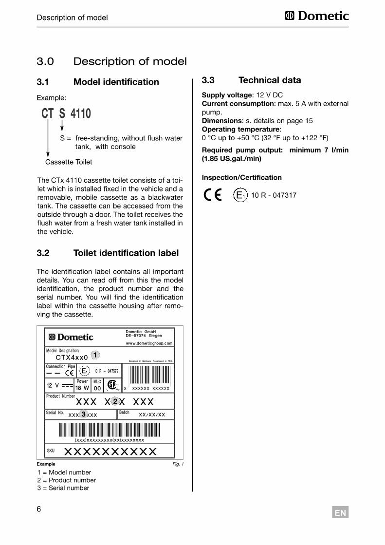
1 = Model number2 = Product number3 = Serial number
The identification label contains all importantdetails. You can read off from this the modelidentification, the product number and theserial number. You will find the identificationlabel within the cassette housing after remo-ving the cassette.
3.2 Toilet identification label
3.0 Description of model
3.1 Model identification
The CTx 4110 cassette toilet consists of a toi-let which is installed fixed in the vehicle and aremovable, mobile cassette as a blackwatertank. The cassette can be accessed from theoutside through a door. The toilet receives theflush water from a fresh water tank installed inthe vehicle.
CT S 4110
Cassette Toilet
S = free-standing, without flush watertank, with console
Example:
Fig. 1Example
1
2
3
Supply voltage: 12 V DCCurrent consumption: max. 5 A with externalpump.Dimensions: s. details on page 15 Operating temperature:0 °C up to +50 °C (32 °F up to +122 °F)
Required pump output: minimum 7 l/min(1.85 US.gal./min)
3.3 Technical data
Inspection/Certification
10 R - 047317E1
7EN
Installing the toilet
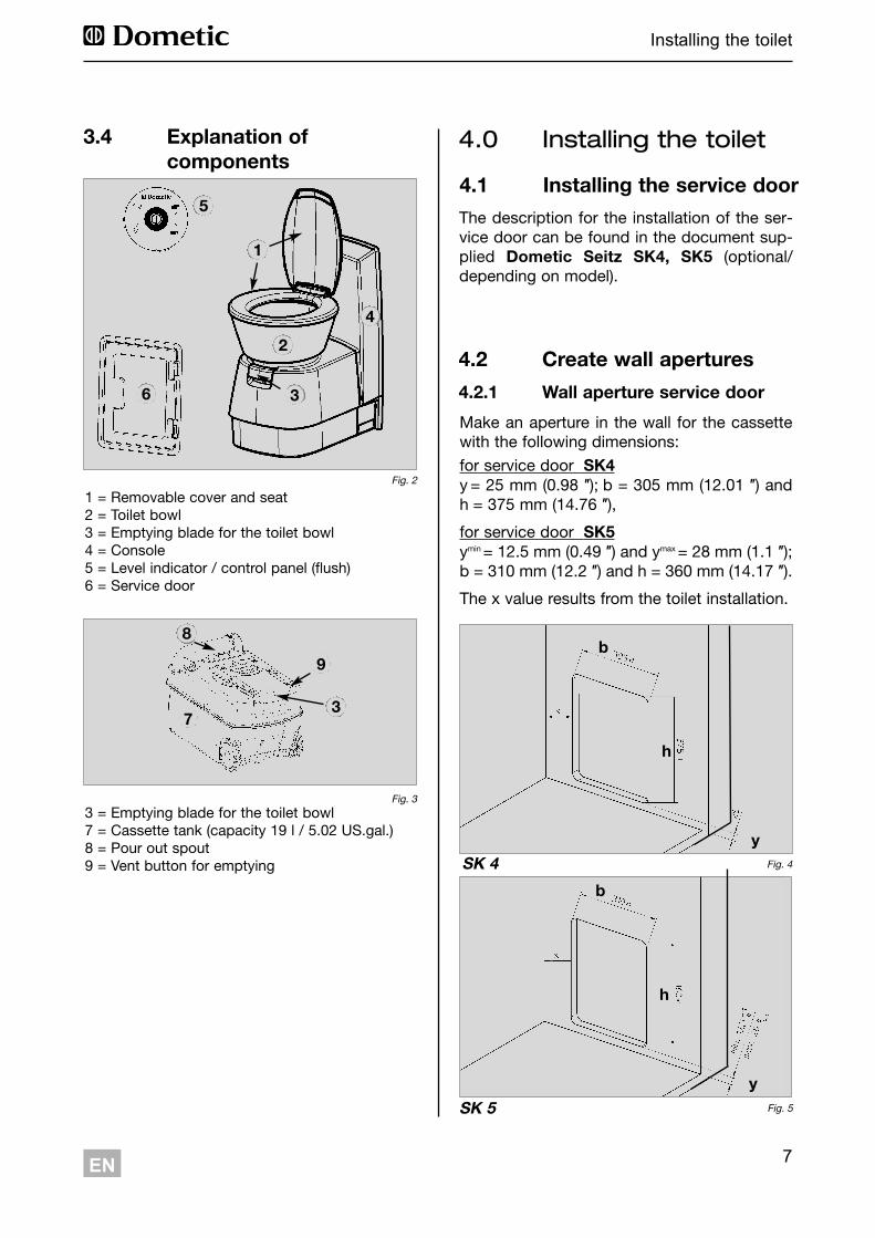
4.2 Create wall apertures
The description for the installation of the ser-vice door can be found in the document sup-plied Dometic Seitz SK4, SK5 (optional/depending on model).
Make an aperture in the wall for the cassettewith the following dimensions: for service door SK4y = 25 mm (0.98 ″); b = 305 mm (12.01 ″) andh = 375 mm (14.76 ″), for service door SK5ymin = 12.5 mm (0.49 ″) and ymax = 28 mm (1.1 ″);b = 310 mm (12.2 ″) and h = 360 mm (14.17 ″). The x value results from the toilet installation.
Fig. 5SK 5
SK 4 Fig. 4
b
h
y
b
h
y
4.2.1 Wall aperture service door
4.1 Installing the service door
4.0 Installing the toilet
1 = Removable cover and seat2 = Toilet bowl3 = Emptying blade for the toilet bowl4 = Console 5 = Level indicator / control panel (flush)6 = Service door
3.4 Explanation ofcomponents
Fig. 2
3 = Emptying blade for the toilet bowl7 = Cassette tank (capacity 19 l / 5.02 US.gal.)8 = Pour out spout9 = Vent button for emptying
Fig. 3
73
9
8
2
4
3
1
5
6
8
Installing the toilet
EN
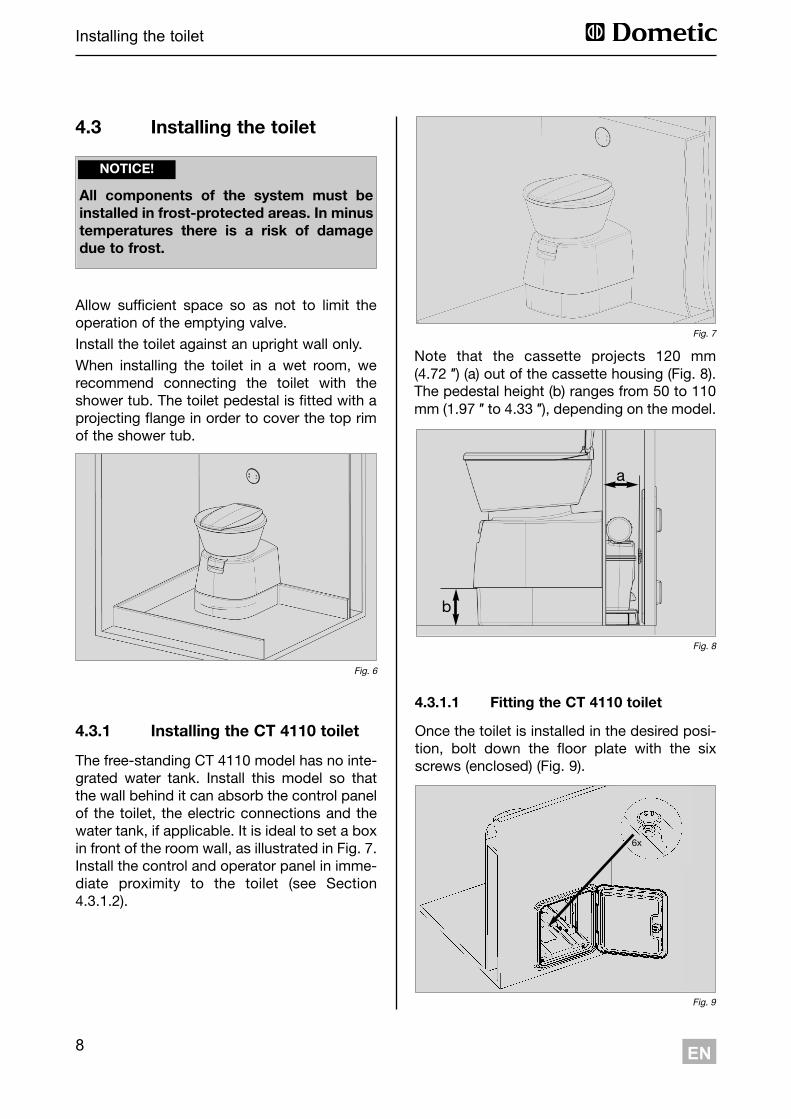
The free-standing CT 4110 model has no inte-grated water tank. Install this model so thatthe wall behind it can absorb the control panelof the toilet, the electric connections and thewater tank, if applicable. It is ideal to set a boxin front of the room wall, as illustrated in Fig. 7.Install the control and operator panel in imme-diate proximity to the toilet (see Section4.3.1.2).
Note that the cassette projects 120 mm(4.72 ″) (a) out of the cassette housing (Fig. 8).The pedestal height (b) ranges from 50 to 110mm (1.97 ″ to 4.33 ″), depending on the model.
4.3.1 Installing the CT 4110 toilet
Fig. 7
Fig. 8
a
b
4.3.1.1 Fitting the CT 4110 toilet
Once the toilet is installed in the desired posi-tion, bolt down the floor plate with the sixscrews (enclosed) (Fig. 9).
Fig. 9
6x
4.3 Installing the toilet
Allow sufficient space so as not to limit theoperation of the emptying valve.Install the toilet against an upright wall only.When installing the toilet in a wet room, werecommend connecting the toilet with theshower tub. The toilet pedestal is fitted with aprojecting flange in order to cover the top rimof the shower tub.
Fig. 6
All components of the system must beinstalled in frost-protected areas. In minustemperatures there is a risk of damagedue to frost.
NOTICE!
9
Installing the toilet
EN
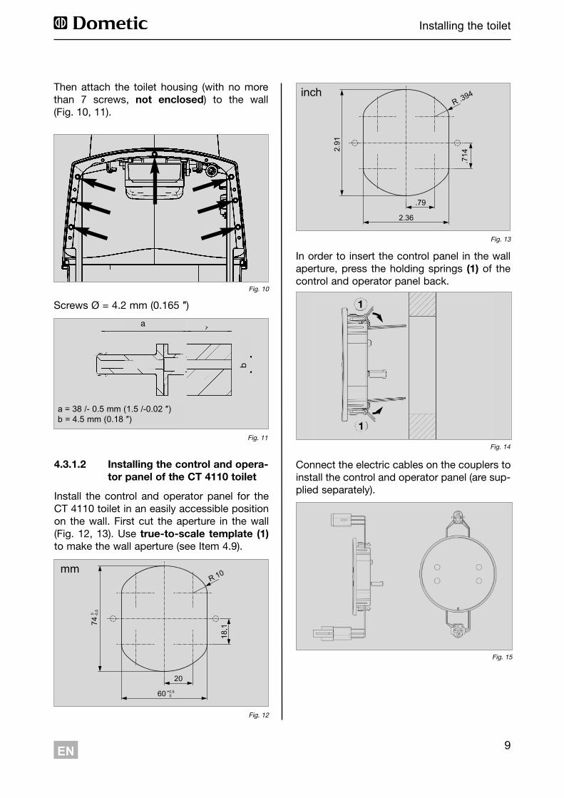
Then attach the toilet housing (with no morethan 7 screws, not enclosed) to the wall(Fig. 10, 11).
Fig. 10
Screws Ø = 4.2 mm (0.165 ″)
Fig. 11
a
a = 38 /- 0.5 mm (1.5 /-0.02 ″)b = 4.5 mm (0.18 ″)
b
Fig. 12
20
18,1
R 10
60 +0,50
74-0
,50
Fig. 13
.79
.714
R .394
2.36
2.91
4.3.1.2 Installing the control and opera-tor panel of the CT 4110 toilet
Install the control and operator panel for theCT 4110 toilet in an easily accessible positionon the wall. First cut the aperture in the wall(Fig. 12, 13). Use true-to-scale template (1)to make the wall aperture (see Item 4.9).
Connect the electric cables on the couplers toinstall the control and operator panel (are sup-plied separately).
In order to insert the control panel in the wallaperture, press the holding springs (1) of thecontrol and operator panel back.
Fig. 14
Fig. 15
1
1
inch
mm

10 EN
Installing the toilet
The CTS 4110 model has no integrated watertank.
The control and operator panel is integrated inthe housing with this model.
This toilet can be installed directly against theroom wall (see Fig. below). To fit the toilet andthe console, a previously installed wall holderis used (see Section 4.3.2.1).
The pedestal height(b) amounts 110 mm(4.33 ″).
4.3.2 Placing the CTS 4110 toilet
Fig. 18
b
Fig. 16
Fig. 17
4.3.2.1 Fitting the wall holder
Fit the wall holder (Fig. 19) in the designatedposition (see table, Fig. 20, 21)
Fig. 19
Fig. 21
a
b
Fitting height of the wall holder:
Model a b
CTS 4xxx 90 mm (3.54 ″) 651.5 mm (25.65 ″)
Fig. 20
11EN
Installing the toilet
Fig. 25
1
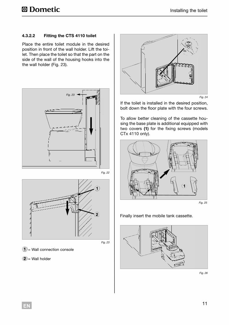
Place the entire toilet module in the desiredposition in front of the wall holder. Lift the toi-let. Then place the toilet so that the part on theside of the wall of the housing hooks into thethe wall holder (Fig. 23).
Fig. 23
4.3.2.2 Fitting the CTS 4110 toilet
Fig. 22
Fig. 23
1
2
1 = Wall connection console
2 = Wall holder
If the toilet is installed in the desired position,bolt down the floor plate with the four screws.
To allow better cleaning of the cassette hou-sing the base plate is additional equipped withtwo covers (1) for the fixing screws (modelsCTx 4110 only).
Finally insert the mobile tank cassette.
Fig. 26
Fig. 24
6x
1
2
12 EN
Installing the toilet
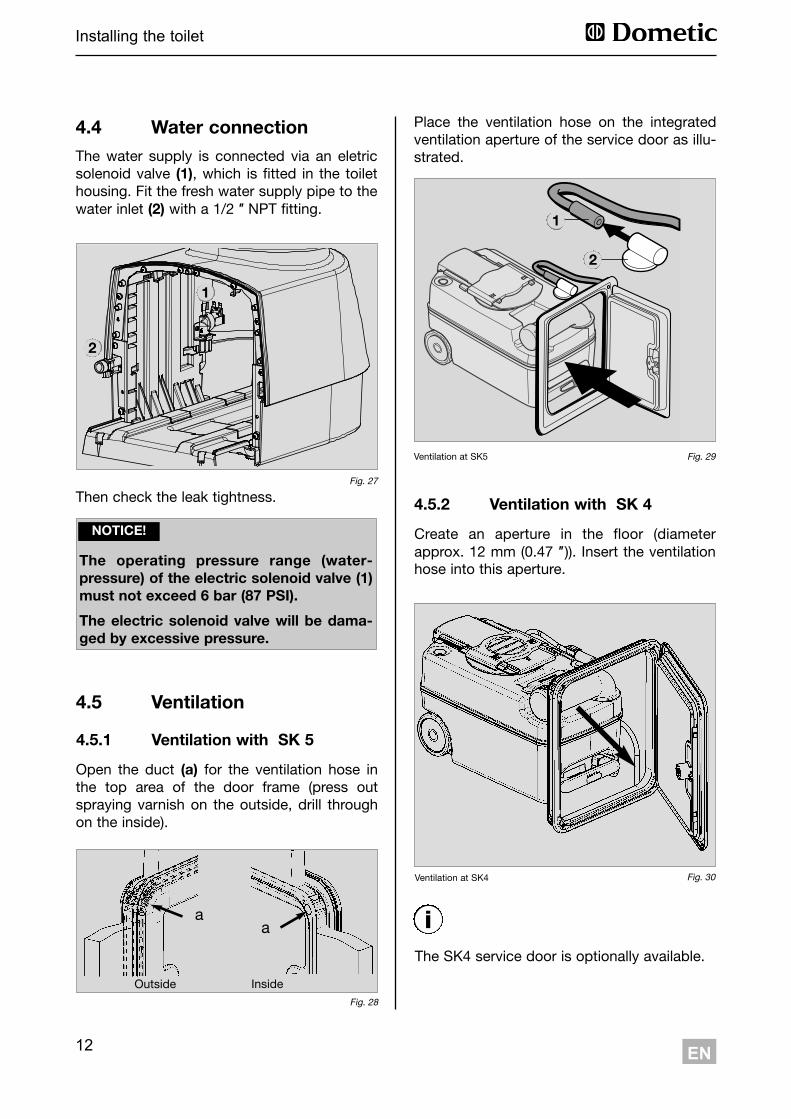
4.4 Water connectionThe water supply is connected via an eletricsolenoid valve (1), which is fitted in the toilethousing. Fit the fresh water supply pipe to thewater inlet (2) with a 1/2 ″ NPT fitting.
Then check the leak tightness.Fig. 27
1
2
The operating pressure range (water -pressure) of the electric solenoid valve (1)must not exceed 6 bar (87 PSI).
The electric solenoid valve will be dama-ged by excessive pressure.
NOTICE!
4.5 Ventilation
Place the ventilation hose on the integratedventilation aperture of the service door as illu-strated.
Fig. 29Ventilation at SK5
Ventilation at SK4 Fig. 30
Fig. 28
Outside Inside
aa
Open the duct (a) for the ventilation hose inthe top area of the door frame (press outspraying varnish on the outside, drill throughon the inside).
4.5.1 Ventilation with SK 5
Create an aperture in the floor (diameterapprox. 12 mm (0.47 ″)). Insert the ventilationhose into this aperture.
4.5.2 Ventilation with SK 4
The SK4 service door is optionally available.
1
2
i
13EN
Installing the toilet
Fig. 32
Fig. 31
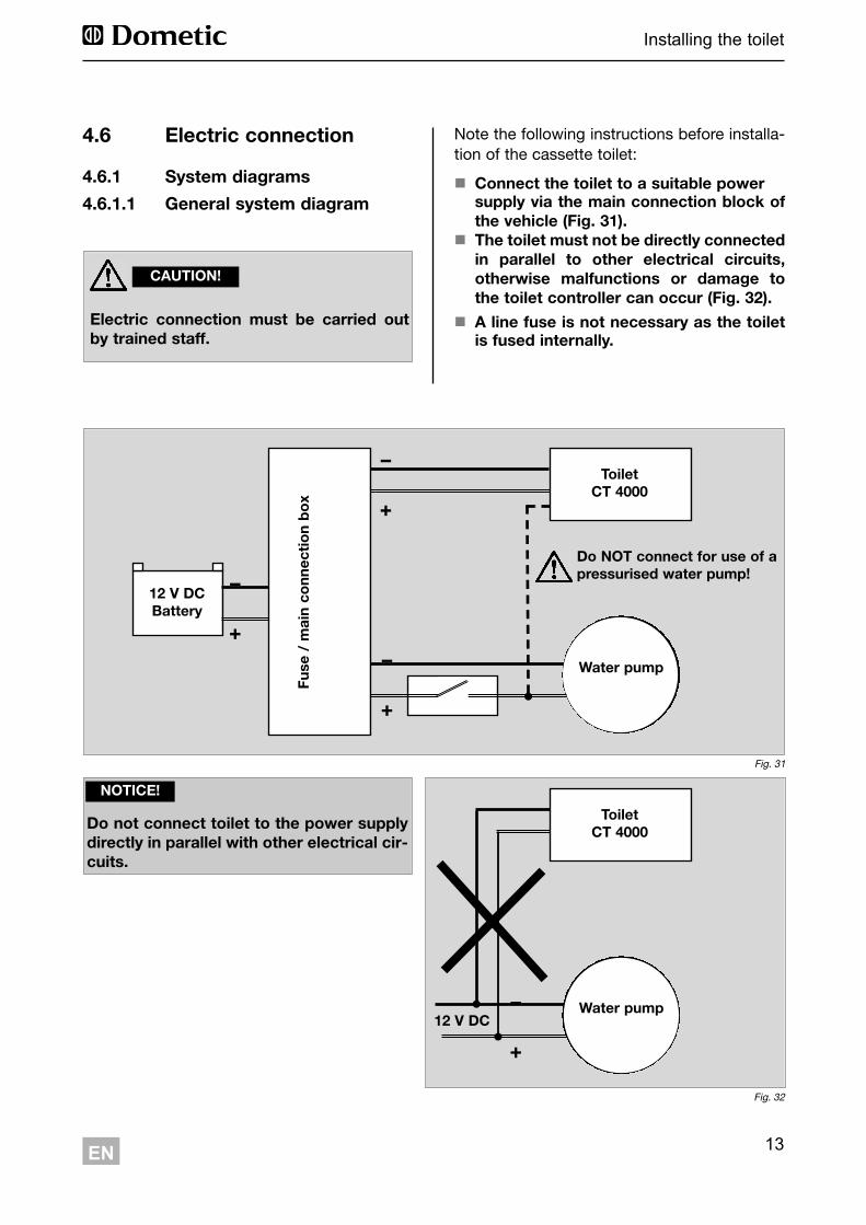
4.6 Electric connection
4.6.1 System diagrams4.6.1.1 General system diagram
Electric connection must be carried outby trained staff.
CAUTION!
Note the following instructions before installa-tion of the cassette toilet:
! Connect the toilet to a suitable power supply via the main connection block ofthe vehicle (Fig. 31).The toilet must not be directly connected!in parallel to other electrical circuits,otherwise malfunctions or damage tothe toilet controller can occur (Fig. 32).
! A line fuse is not necessary as the toiletis fused internally.
12 V DCBattery
Fuse
/ m
ain
conn
ectio
n bo
x
ToiletCT 4000
Water pump
Do NOT connect for use of apressurised water pump!
ToiletCT 4000
Water pump
+
!
+
!
+
!
+
!12 V DC
Do not connect toilet to the power supplydirectly in parallel with other electrical cir-cuits.
NOTICE!
14 EN
Installing the toilet
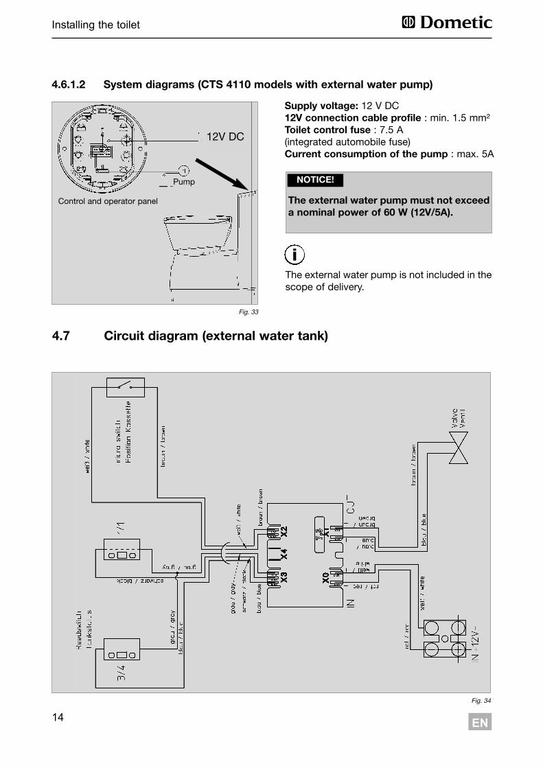
4.7 Circuit diagram (external water tank)
Fig. 34
4.6.1.2 System diagrams (CTS 4110 models with external water pump)
Supply voltage: 12 V DC12V connection cable profile : min. 1.5 mm²Toilet control fuse : 7.5 A (integrated automobile fuse)Current consumption of the pump : max. 5A
The external water pump is not included in thescope of delivery.
The external water pump must not exceeda nominal power of 60 W (12V/5A).
NOTICE!
Fig. 33
12V DC
Control and operator panel
Pump
i
15EN
Installing the toilet
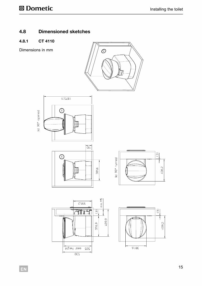
4.8 Dimensioned sketches
4.8.1 CT 4110
Dimensions in mm
16
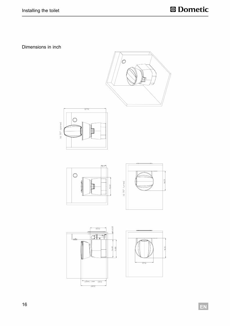
Installing the toilet
EN
Dimensions in inch
17EN
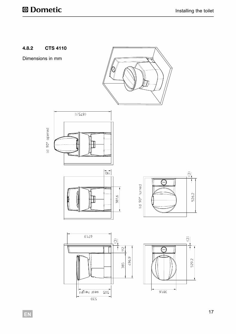
Installing the toilet
4.8.2 CTS 4110
Dimensions in mm
18
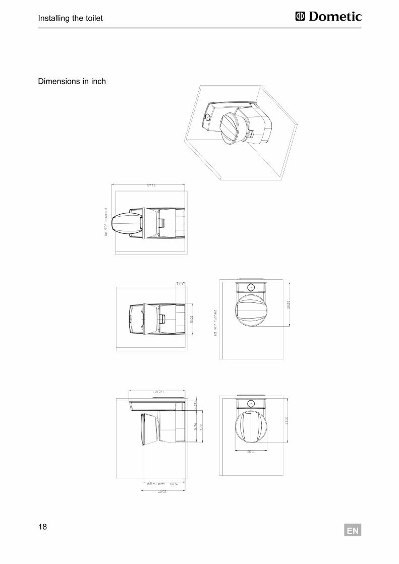
Installing the toilet
EN
Dimensions in inch

19EN
Installing the toilet
4.9 Template for control and operator panel installation
Original size
1