ct4 · 2018-11-15 · 2 models in the range (ct4-500 and ct4-1000) which can be fitted with a...
TRANSCRIPT
© 2014 by Huchez Treuils S.A.S.
Shear legs / Tripods
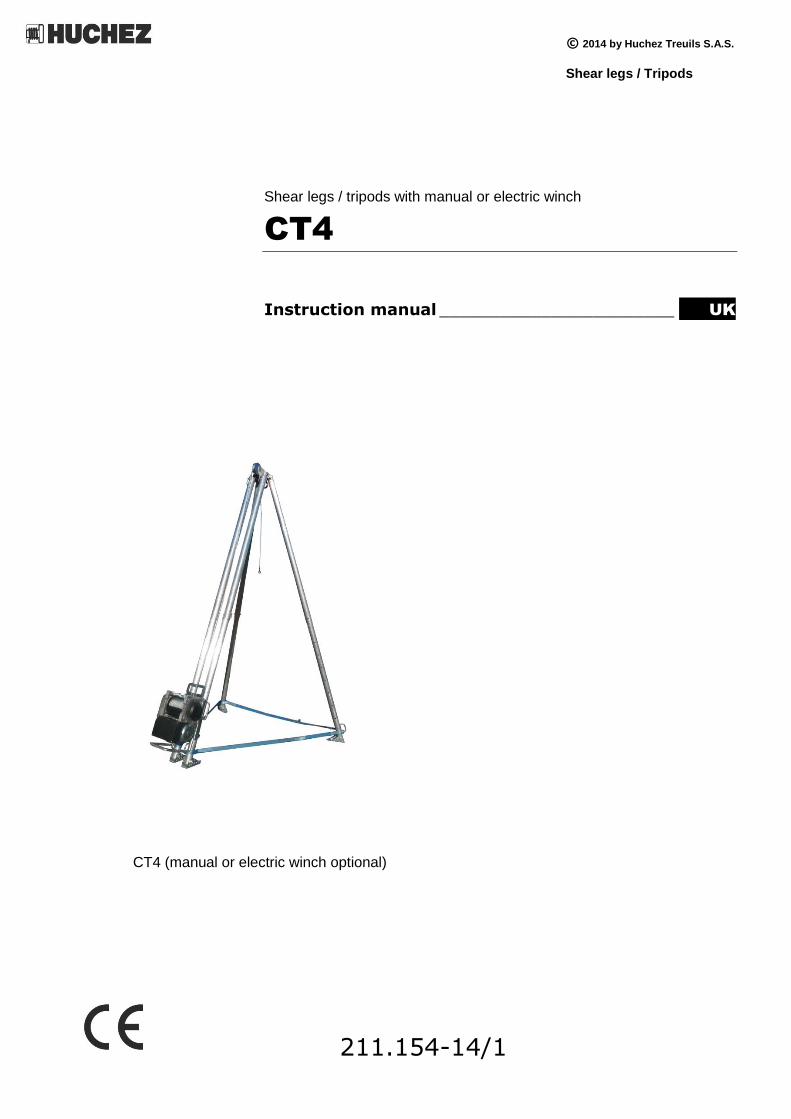
Shear legs / tripods with manual or electric winch
CT4
Instruction manual _______________________ UK
CT4 (manual or electric winch optional)
211.154-14/1

© 2014 by Huchez Treuils S.A.S.
Translation of the original instruction manual 2UK All rights reserved
To ensure the constant improvement of its products, HUCHEZ reserves the right to change the equipment as described below and, in this case, to supply products which differ from the illustrations in this instruction manual.
All rights reserved
Contents
1. General warning p. 3
2. Brief presentation of appliances p. 3
3. Handling - Storage p. 5
4. Use, assembly and commissioning p. 5
5. Maintenance p. 5
6. Prohibitions for use p. 6
7. Statutory, compulsory checks by the user p. 6
8. Putting out of operation p. 6
9. Specimens declaration of conformity p. 7
10. Annexes p. 8

© 2014 by Huchez Treuils S.A.S.
Translation of the original instruction manual 3UK All rights reserved
1 – General notice
However, gins supplied with manual or electric lifting devices are considered machines in compliance with
European regulations and, in particular, with the Machinery Directive 2006/42/EC.
Before using this tripod, with safety of use of the equipment and efficiency in mind, it is vital for you
to become familiar with this instruction manual and to comply with all the recommendations.
This instruction manual must be kept available to all operators. The manufacturer shall provide
additional copies on simple request.
The tripods equipped with a lifting appliance (hoist) are designed to carry out lifting operations in a
working area specified. Please make sure the operator is qualified to carry out the operation in the
conditions laid down in this manual in order to respect the safety of persons and the environment.
Never use this tripod with a load exceeding the maximum working load specified.
The tripods may not, under any circumstance, be used to lift staff.
Before each use, the operator shall check the clearing of the working area, correct condition of the
lifting appliance, its rope or chain, hook, marking, as well as its stability.
The manufacturer declines all responsability for consequences due to the use or installation of
appliances not provided in this manual, together with the consequences of dismantling, alterations or
replacements or original parts with parts or components of other sources without its written
agreement.
2 - Presentation of appliances
2 models in the range (CT4-500 and CT4-1000) which can be fitted with a manual or electric winch
(optional) with a view to lifting loads of between de 300 and 1,000 kg depending on the equipment
selected.
2.1. Construction :
Aluminium legs individually adjustable in 160 mm steps.
These telescopic aluminium tripods are fitted with:
- a fixing plate on a double post enabling assembly of an optional manual or electric winch, - a pulley which is easy to dismantle in order to slip the rope on whenever it is used, - three independent textile straps allowing the distance between the legs to be controlled at
all times.
Each leg has a handle at its lower part and an articulated foot with a flat side for hard ground
and a spade-shaped end for soft ground.
High-strength cast aluminium head (500 – 1000) with multiple anchor points for fitting a
pulley, a second hook for a tackle, a chain hoist….
Legs hold together by 3 safety straps each fitted with a carabiner.
Light and compact when retracted: 2.36 m for models CT4-500 and CT4-1000 with a height of 3 m,
3.36 m for models CT4-500 with a height of 4 m.

© 2014 by Huchez Treuils S.A.S.
Translation of the original instruction manual 4UK All rights reserved
2.2. Dimensions:
2.2.1.CT4 500 kg - 4 meters
The feet are inscribed in a circle of 2.90 m to the 4th
hole and 3.45 m beyond.
2.2.2. CT4 500 kg - 3 meters and CT4 1000 kg
Les pieds sont inscrits dans un cercle de 2 m jusqu’au 4ème trou et 2,30 m au-delà.
The feet are inscribed in a circle of 2 m to the 4th hole
and 2.30 m beyond.
2800
4200
Positions 1 to 4
Positions 5 to 10
1900
3300
Positions 1 to 4
Positions 5 to 10

© 2014 by Huchez Treuils S.A.S.
Translation of the original instruction manual 5UK All rights reserved
2.3. Operation
Telescopic system and the adjustability of feet enable tripods to be easily adapted to all kinds of sites for use in optimum conditions. The legs are hold together by 3 safety independent straps each fitted with a carabiner.
3 – Handling - Storage
Made of aluminium, tripods are light and easily handled or stored. It is recommended to store away from the elements.
4 – Use, assembly and commissioning
Ensure of the quality of the ground
Draw up the appliance by checking the levelling
The kit consists of:
- a winch fixing plate
- a fixed spindle and 2 safety cables
- a removable spindle
Ref. CT4 500
3 CT4 500
4 CT4 500
3 CT4 500
4 CT4 1000 CT4 1000
Capacity kg 250/350/500 500 1000 1000
Height under tripod head (mini.-
maxi.) m 1.90-3.30 2.80-4.20 1.90-3.30 2.80-4.20 1.90-3.30 1.90-3.30
Manual or electric winch (optional) TRBoxter
250/350/500 kg 1Ph – 230 V
Manibox GR 500
TRBoxter 500
reeved, 3 Ph–
230/400V
Manibox GR 1000
Lifting height m 56/56/42 18 21 30

© 2014 by Huchez Treuils S.A.S.
Translation of the original instruction manual 6UK All rights reserved
a. Position the plate fitted with its winch on the fixed spindle located at the level of
the 1st hole at the bottom of the double post then push the whole against the tripod tubes. Lock on both sides using the safety cable lynch pins.
b. Push the removable spindle through the tubes and the plate, then lock this spindle using the cable
pin attached to the plate.
4.2 Assembly/disassembly of the pulley
Remove the top of the 2 cables of the pulley cover on the head of the tripod to free
the through axle.
This pulley can now be dismantled easily to fit the rope every time it is used without removing the legs.
© 2014 by Huchez Treuils S.A.S.
Translation of the original instruction manual 7UK All rights reserved
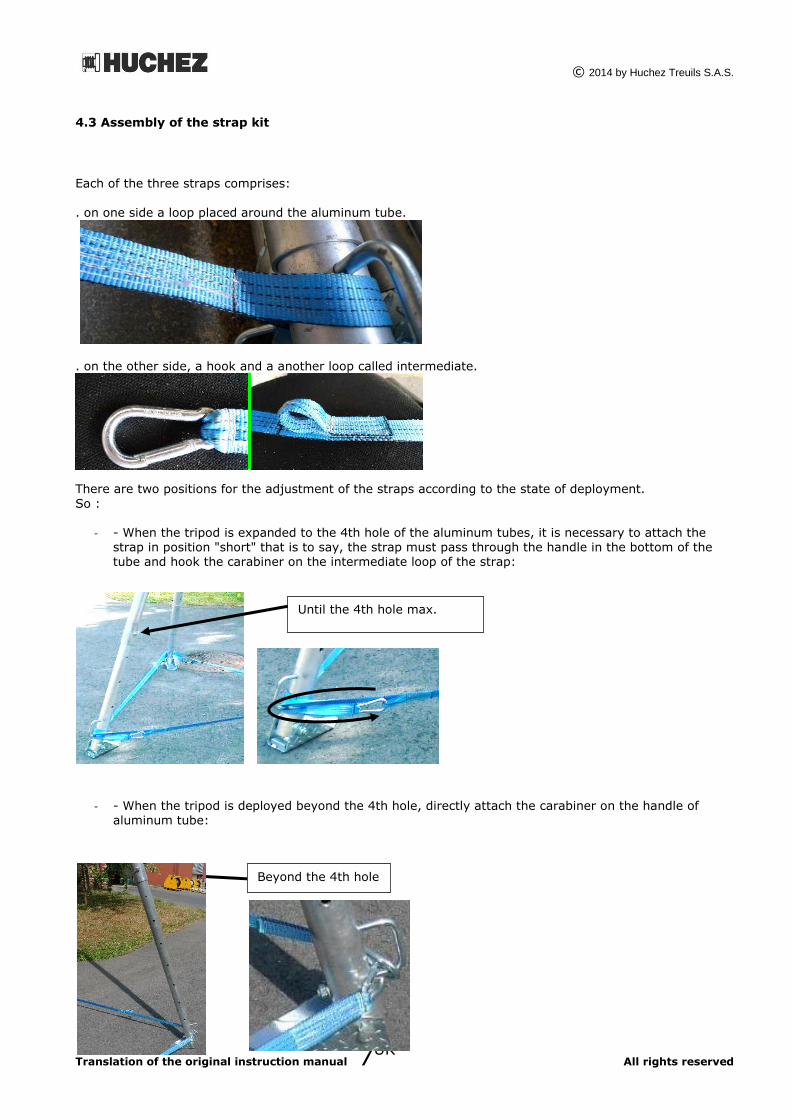
4.3 Assembly of the strap kit
Each of the three straps comprises:
. on one side a loop placed around the aluminum tube.
. on the other side, a hook and a another loop called intermediate.
There are two positions for the adjustment of the straps according to the state of deployment.
So :
- - When the tripod is expanded to the 4th hole of the aluminum tubes, it is necessary to attach the strap in position "short" that is to say, the strap must pass through the handle in the bottom of the tube and hook the carabiner on the intermediate loop of the strap:
- - When the tripod is deployed beyond the 4th hole, directly attach the carabiner on the handle of aluminum tube:
Until the 4th hole max.
Beyond the 4th hole
© 2014 by Huchez Treuils S.A.S.
Translation of the original instruction manual 8UK All rights reserved
The legs are fastened to one another by the 3 textiles straps, each fitted with a carabiner. Whenever in use, the 3 legs must be within a circle with a diameter of:
2.00 m (deployment up to the 4th hole) or 2.30 m (deployment beyond the 4th hole) for models 3 m in height.
2.90 m (deployment up to the 4th hole) or 3.45 m (deployment beyond the 4th hole) for models 4 m in height.
5 – Maintenance
Check the feet fixing and the anchor head regularly, and also the self-locking pins.
Also check the state of the lifting appliance according to the specifications in the instruction manual and in particular, the chain or cable, the hook and the brake.
6 – Prohibitions for use
Before any use, make sure there is no risk of overloading due to: adherence to floor, suction, jamming,
etc.
You are be warned against any of the following improper uses or handling operations:
It is prohibited to:
Lift loads exceeding the rated load specified on the plate of the appliance;
Pull sideways;
Swing the load;
Use the appliance to lift staff;
Go under the load;
Use hooks without catches, not suitable for the loads specified on the appliance or in bad condition;
Insert objects into the moving parts;
Take action on appliances under load;
Let down the load on free fall;
Use the rope or the chain of the appliance as a sling;
Use the appliances for operations different from those they are designed for;
Use parts or components different from the manufacturer’s original parts or components;
Reeve by positioning the fixed point on the lifting appliance.
7 – Statutory, compulsory checks by the
user
This appliance has been subjected to the following tests in the factory:
dynamic proof test at coefficient 1.1 static proof test:
- at coefficient 1.5 for appliances moved by human strength - at coefficient 1.25 for the others
A periodic maintenance check is required at least once a year.
The user must keep a safety register R.233.11).
© 2014 by Huchez Treuils S.A.S.
Translation of the original instruction manual 9UK All rights reserved
In compliance with the regulations, the user must set up an inspection book where all the actions and
inspections conducted on the appliance shall be recorded (FEM rule 9755).
8 – Putting out of operation
When the equipment is in a state of decay likely to create risks, the user is obliged to do away with this material i.e.: put it out of operation, dismantle it if required.
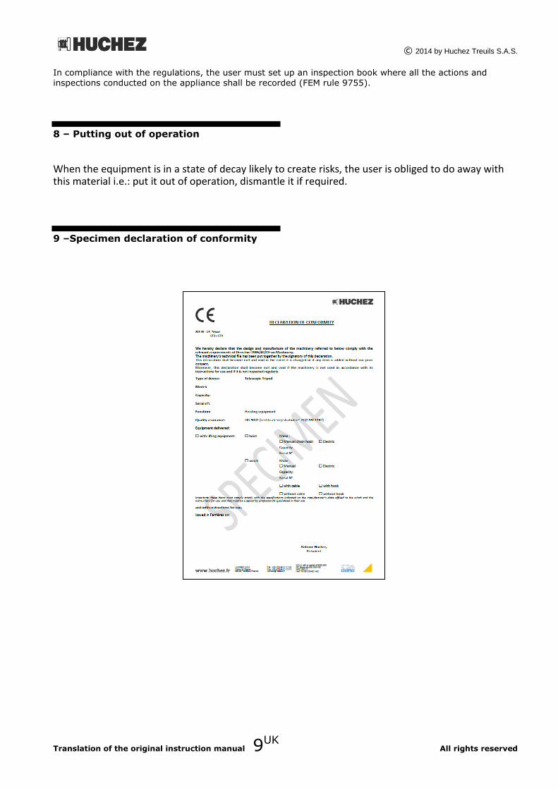
9 –Specimen declaration of conformity

© 2014 by Huchez Treuils S.A.S.
Translation of the original instruction manual 10UK All rights reserved
10 – Annexes
A – Manual of the winch
B –Part references
C – Maintenance booklet

© 2014 by Huchez Treuils S.A.S.
Translation of the original instruction manual 11UK All rights reserved
A – Manual of the winch
Enclosed.

© 2014 by Huchez Treuils S.A.S.
Translation of the original instruction manual 12UK All rights reserved
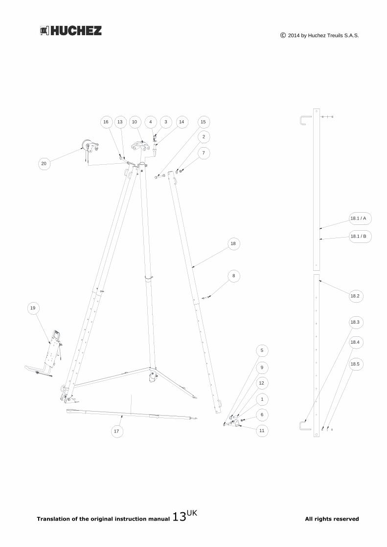
B – Part references
Bill of materials - CT4-500 and CT4-1000
Art. Qty Part
number Description
Art. Qty Part
number Description
1 4 13214 Washer M 16
12 4 20605 Shoe spacer
2 4 13216 Washer M 20
13 1 20609-00 TOP AXLE
3 1 13290 Nut M27
14 1 20613 Ring C3127C2
4 1 13310 Washer M 27
15 2 20614 Screw TH M20x130
5 4 13415 Screw TH M16 x 110
16 2 20618-01 Pin meca
6 4 13485 Nut H FR M16
17 3 24423 Strap 2 m (CT4 500 – 3 m)°
7 2 13597 Nut H FR M20
3 24059 Strap 3 m (CT4 500 – 4 m and CT4 1000)
8 4 1767 Safety pin
18 4 Foot CT4 500-1000
9 4 1768 Spring washer 50x25.4x3
19 1 CT4 500 plate for TRBoxter, MANIBOX GR500
10 1 20601 Head 1 CT4 500 plate for MANIBOX GR1000
11 4 20604 Brace
20 1 Offset pulley kit
Art. Qty Part
number Description
Art. Qty Part
number Description
18.1 / A 1 20602 Upper foot 3 m
18.3 2 20684 Retention strap ring
18.2 / B 1 21931 Upper foot 4 m
18.4 4 13021 Nut M12
18.2 1 20603 Lower foot
18.5 2 13212 Washer M12
© 2014 by Huchez Treuils S.A.S.
Translation of the original instruction manual 13UK All rights reserved
9
12
1
5
6
18
8
16 14 10
2
3 4 15
7
18.5
18.4
18.2
18.3
18.1 / A
18.1 / B
13
19
20
11 17
© 2014 by Huchez Treuils S.A.S.
Translation of the original instruction manual 14UK All rights reserved
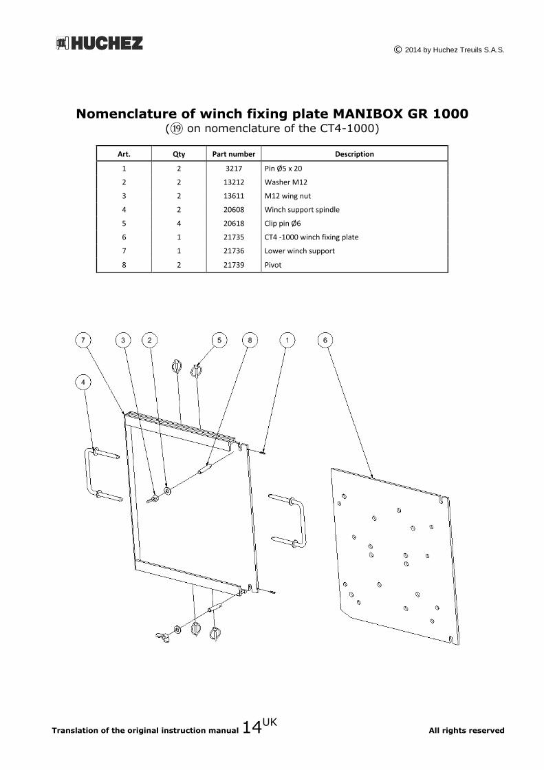
Nomenclature of winch fixing plate MANIBOX GR 1000 (⑲ on nomenclature of the CT4-1000)
Art. Qty Part number Description
1 2 3217 Pin Ø5 x 20
2 2 13212 Washer M12
3 2 13611 M12 wing nut
4 2 20608 Winch support spindle
5 4 20618 Clip pin Ø6
6 1 21735 CT4 -1000 winch fixing plate
7 1 21736 Lower winch support
8 2 21739 Pivot

© 2014 by Huchez Treuils S.A.S.
Translation of the original instruction manual 15UK All rights reserved
Nomenclature of winch fixing plate TRBoxter or MANIBOX
GR500 (⑲ on nomenclature of the CT4-500 and CT4-1000)
Art. Qty Part
number Description
Art. Qty Part
number Description
1 4 13009 Nut M5
10 2 13482 Nut H FR M3
2 4 13010 Nut M6
11 4 13541 Screw TFHC M6x20
3 4 13123 Screw CHC M5x16
12 2 22458 Plastic handle
4 2 13124 Screw CHC M5x20
13 1 24060 CT4 500 plate SE
5 2 13171 Screw TC M3x10
14 1 24065 Spindle axle 1
6 1 13450 Handle U
15 1 24066 Spindle axle 2
7 3 13451 Wire lg 200
16 1 24067 Fixed spindle
8 2 13452 Clip Ø12
17 1 24068 Bar
9 3 13453 Clip pins Ø4.5
6 4 13 15 9
14
16
8
7
10
5
17
2
11
12 3 1

© 2014 by Huchez Treuils S.A.S.
Translation of the original instruction manual 16UK All rights reserved
Nomenclature for offset pulley unit (⑳ on nomenclature of the CT4-500 and CT4-1000)
Art. Qty Part
number Description
Art. Qty
Part
number Description
1 1 13217 Washer M 24
6 1 24420 Offset pulley axle
2 1 13362 Nut H FR M24
7 1 24421 Pulley
3 2 13451 Wire lg 200
8 1 24422 Holding axle
4 2 13453 Clip pins Ø4.5
9 2 3642 Bearing 6205
5 1 24416 Pulley offset SE

© 2014 by Huchez Treuils S.A.S.
Translation of the original instruction manual 17UK All rights reserved
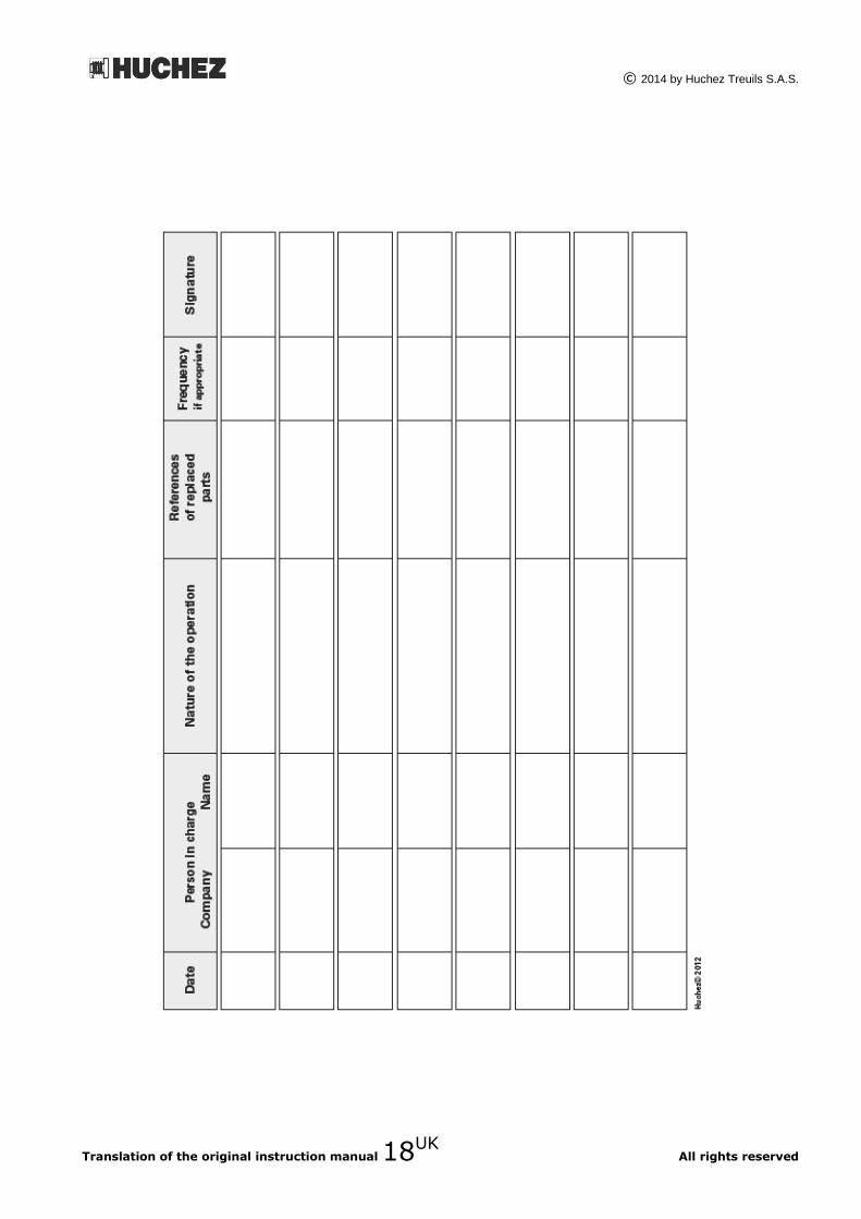
C – Maintenance booklet.
The English version of the maintenance booklet for our lifting winches can be downloaded from our
website www.huchez.fr/uk under the heading "After sales services”.
© 2014 by Huchez Treuils S.A.S.
Translation of the original instruction manual 18UK All rights reserved