ct30/ct33 low voltage thermostat owner's manual - honeywell · ct30/ct33 low-voltage...
TRANSCRIPT
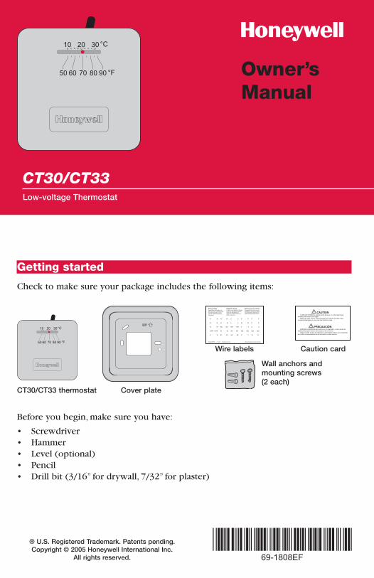
CT30/CT33Low-voltage Thermostat
Owner’sManual
Getting started
Before you begin, make sure you have:
• Screwdriver• Hammer• Level (optional)• Pencil• Drill bit (3/16” for drywall, 7/32” for plaster)
Caution cardWire labels
Wall anchors andmounting screws(2 each)
CT30/CT33 thermostat Cover plate
Check to make sure your package includes the following items:
® U.S. Registered Trademark. Patents pending. Copyright © 2005 Honeywell International Inc.
All rights reserved.
Owner’s Manual
2
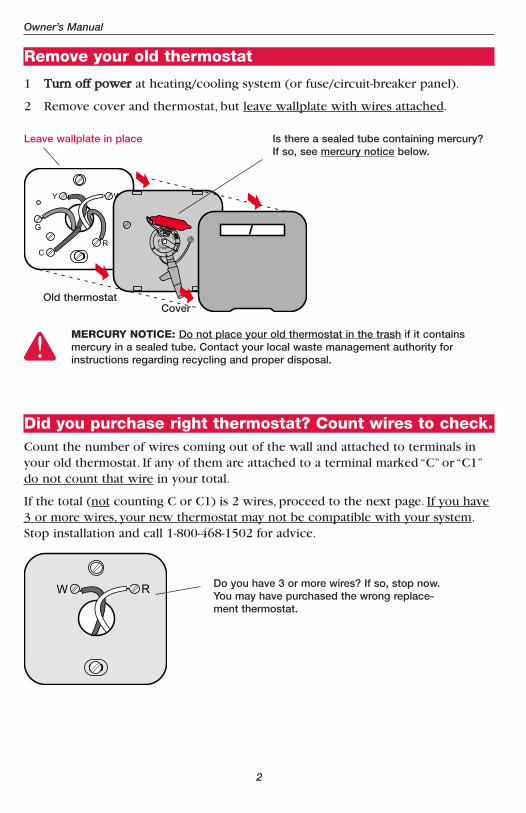
Remove your old thermostat
1 TTuurrnn ooffff ppoowweerr at heating/cooling system (or fuse/circuit-breaker panel).
2 Remove cover and thermostat, but leave wallplate with wires attached.
Old thermostat
Leave wallplate in place Is there a sealed tube containing mercury? If so, see mercury notice below.
Cover
MERCURY NOTICE: Do not place your old thermostat in the trash if it contains mercury in a sealed tube. Contact your local waste management authority for instructions regarding recycling and proper disposal.
Did you purchase right thermostat? Count wires to check.Count the number of wires coming out of the wall and attached to terminals inyour old thermostat. If any of them are attached to a terminal marked “C” or “C1”do not count that wire in your total.
If the total (not counting C or C1) is 2 wires, proceed to the next page. If you have3 or more wires, your new thermostat may not be compatible with your system.Stop installation and call 1-800-468-1502 for advice.
Do you have 3 or more wires? If so, stop now.You may have purchased the wrong replace-ment thermostat.
CT30/CT33 Low-voltage Thermostat
3
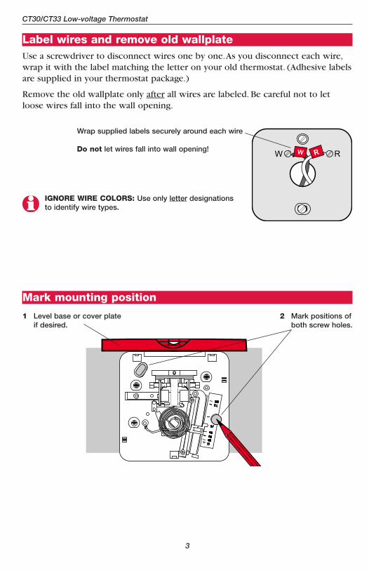
Label wires and remove old wallplateUse a screwdriver to disconnect wires one by one.As you disconnect each wire,wrap it with the label matching the letter on your old thermostat. (Adhesive labelsare supplied in your thermostat package.)
Remove the old wallplate only after all wires are labeled. Be careful not to letloose wires fall into the wall opening.
Wrap supplied labels securely around each wire
Do not let wires fall into wall opening!
IGNORE WIRE COLORS: Use only letter designationsto identify wire types.
Mark mounting position
1 Level base or cover plate if desired.
2 Mark positions ofboth screw holes.
Owner’s Manual
4
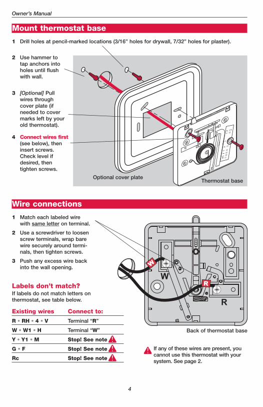
Wire connections
1 Match each labeled wirewith same letter on terminal.
2 Use a screwdriver to loosenscrew terminals, wrap barewire securely around termi-nals, then tighten screws.
3 Push any excess wire backinto the wall opening.
Labels don’t match?If labels do not match letters onthermostat, see table below.
Mount thermostat base
1 Drill holes at pencil-marked locations (3/16” holes for drywall, 7/32” holes for plaster).
2 Use hammer totap anchors intoholes until flushwith wall.
3 [Optional] Pullwires throughcover plate (ifneeded to covermarks left by yourold thermostat).
4 Connect wires first(see below), theninsert screws.Check level ifdesired, then tighten screws.
Thermostat baseOptional cover plate
Back of thermostat base
Existing wires Connect to:
R • RH • 4 • V Terminal “R”
W • W1 • H Terminal “W”
Y • Y1 • M Stop! See note
G • F Stop! See note
Rc Stop! See note
If any of these wires are present, youcannot use this thermostat with yoursystem. See page 2.
CT30/CT33 Low-voltage Thermostat
5
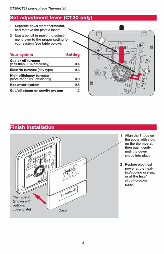
Set adjustment lever (CT30 only)
1 Separate cover from thermostat,and remove the plastic insert.
2 Use a pencil to move the adjust-ment lever to the proper setting foryour system (see table below).
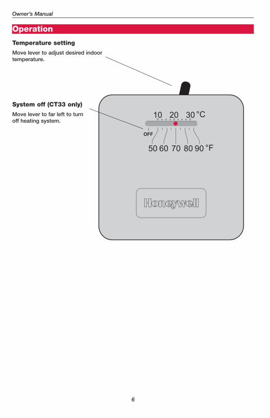
Finish installation
1 Align the 3 tabs onthe cover with slotson the thermostat,then push gentlyuntil the coversnaps into place.
2 Restore electricalpower at the heat-ing/cooling system,or at the fuse/circuit-breakerpanel.
Cover
Thermostat(shown withoptionalcover plate)
Your system Setting
Gas or oil furnace(less than 90% efficiency) 0.4
Electric furnace (any type) 0.3
High efficiency furnace(more than 90% efficiency) 0.8
Hot water system 0.8
Gas/oil steam or gravity system 1.2
Owner’s Manual
6
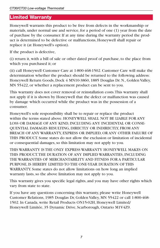
Operation
Temperature setting
Move lever to adjust desired indoortemperature.
System off (CT33 only)
Move lever to far left to turnoff heating system.
CT30/CT33 Low-voltage Thermostat
7
Limited Warranty
Honeywell warrants this product to be free from defects in the workmanship ormaterials, under normal use and service, for a period of one (1) year from the dateof purchase by the consumer. If at any time during the warranty period the prod-uct is determined to be defective or malfunctions, Honeywell shall repair orreplace it (at Honeywell's option).
If the product is defective,
(i) return it, with a bill of sale or other dated proof of purchase, to the place fromwhich you purchased it; or
(ii) call Honeywell Customer Care at 1-800-468-1502. Customer Care will make thedetermination whether the product should be returned to the following address:Honeywell Return Goods, Dock 4 MN10-3860, 1885 Douglas Dr. N., Golden Valley,MN 55422, or whether a replacement product can be sent to you.
This warranty does not cover removal or reinstallation costs.This warranty shallnot apply if it is shown by Honeywell that the defect or malfunction was causedby damage which occurred while the product was in the possession of a consumer.
Honeywell's sole responsibility shall be to repair or replace the product within the terms stated above. HONEYWELL SHALL NOT BE LIABLE FOR ANYLOSS OR DAMAGE OF ANY KIND, INCLUDING ANY INCIDENTAL OR CONSE-QUENTIAL DAMAGES RESULTING, DIRECTLY OR INDIRECTLY, FROM ANYBREACH OF ANY WARRANTY, EXPRESS OR IMPLIED, OR ANY OTHER FAILURE OFTHIS PRODUCT. Some states do not allow the exclusion or limitation of incidentalor consequential damages, so this limitation may not apply to you.
THIS WARRANTY IS THE ONLY EXPRESS WARRANTY HONEYWELL MAKES ONTHIS PRODUCT.THE DURATION OF ANY IMPLIED WARRANTIES, INCLUDINGTHE WARRANTIES OF MERCHANTABILITY AND FITNESS FOR A PARTICULARPURPOSE, IS HEREBY LIMITED TO THE ONE-YEAR DURATION OF THIS WARRANTY. Some states do not allow limitations on how long an implied warranty lasts, so the above limitation may not apply to you.
This warranty gives you specific legal rights, and you may have other rights whichvary from state to state.
If you have any questions concerning this warranty, please write HoneywellCustomer Relations, 1985 Douglas Dr, Golden Valley, MN 55422 or call 1-800-468-1502. In Canada, write Retail Products ON15-02H, Honeywell Limited/Honeywell Limitée, 35 Dynamic Drive, Scarborough, Ontario M1V4Z9.
Need Help?For assistance with this product please visit www.honeywell.com/yourhome
or call Honeywell Customer Care toll-free at 1-800-468-1502
Honeywell International Inc.
1985 Douglas Drive North
Golden Valley, MN 55422
www.honeywell.com/yourhome
Automation and Control Solutions
Printed in U.S.A. on recycledpaper containing at least 10%post-consumer paper fibers.
® U.S. Registered Trademark. © 2005 Honeywell International Inc.Patents pending. All rights reserved.69-1808EF Rev. 03-2005
Honeywell Limited-Honeywell Limitée
35 Dynamic Drive
Scarborough, Ontario M1V 4Z9
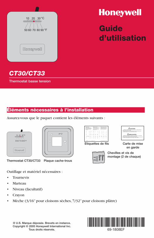
CT30/CT33Thermostat basse tension
Guide d’utilisation
Éléments nécessaires à l’installation
Outillage et matériel nécessaires :
• Tournevis
• Marteau
• Niveau (facultatif)
• Crayon
• Mèche (3/16” pour cloisons sèches, 7/32” pour cloisons plâtre)
Carte de miseen garde
Etiquettes de fils
Chevilles et vis de montage (2 de chaque)
Thermostat CT30/CT33 Plaque cache-trous
Assurez-vous que le paquet contient les éléments suivants :
® U.S. Marque déposée. Brevets en instance. Copyright © 2005 Honeywell International Inc.
Tous droits réservés.
Guide d’utilisation
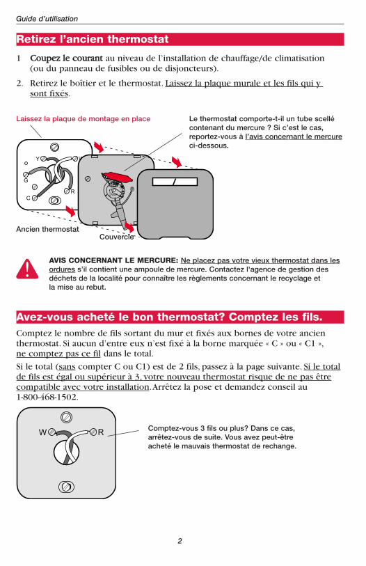
Avez-vous acheté le bon thermostat? Comptez les fils.Comptez le nombre de fils sortant du mur et fixés aux bornes de votre ancienthermostat. Si aucun d’entre eux n’est fixé à la borne marquée « C » ou « C1 »,ne comptez pas ce fil dans le total.
Si le total (sans compter C ou C1) est de 2 fils, passez à la page suivante. Si le totalde fils est égal ou supérieur à 3, votre nouveau thermostat risque de ne pas êtrecompatible avec votre installation.Arrêtez la pose et demandez conseil au 1-800-468-1502.
Comptez-vous 3 fils ou plus? Dans ce cas,arrêtez-vous de suite. Vous avez peut-êtreacheté le mauvais thermostat de rechange.
Retirez l’ancien thermostat
1 CCoouuppeezz llee ccoouurraanntt au niveau de l’installation de chauffage/de climatisation (ou du panneau de fusibles ou de disjoncteurs).
2. Retirez le boîtier et le thermostat. Laissez la plaque murale et les fils qui y sont fixés.
Ancien thermostat
Laissez la plaque de montage en place Le thermostat comporte-t-il un tube scellécontenant du mercure ? Si c’est le cas,reportez-vous à l’avis concernant le mercureci-dessous.
Couvercle
AVIS CONCERNANT LE MERCURE: Ne placez pas votre vieux thermostat dans lesordures s’il contient une ampoule de mercure. Contactez l'agence de gestion desdéchets de la localité pour connaître les règlements concernant le recyclage et la mise au rebut.
2
Thermostat basse tension CT30/CT33
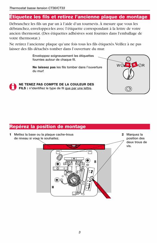
Étiquetez les fils et retirez l’ancienne plaque de montageDébranchez les fils un par un à l’aide d’un tournevis. À mesure que vous lesdébranchez, enveloppez-les avec l’étiquette correspondant à la lettre de votreancien thermostat. (Des étiquettes adhésives sont fournies dans l'emballage devotre thermostat.)
Ne retirez l’ancienne plaque qu’une fois tous les fils étiquetés.Veillez à ne paslaisser des fils détachés tomber dans l’ouverture du mur.
Enveloppez soigneusement les étiquettesfournies autour de chaque fil.
Ne laissez pas les fils tomber dans l’ouverturedu mur!
NE TENEZ PAS COMPTE DE LA COULEUR DESFILS : n'identifiez le type de fil que par une lettre.
Repérez la position de montage
1 Mettez la base ou la plaque cache-trousde niveau si vous le souhaitez.
2 Marquez la position desdeux trous devis.
3
Guide d’utilisation
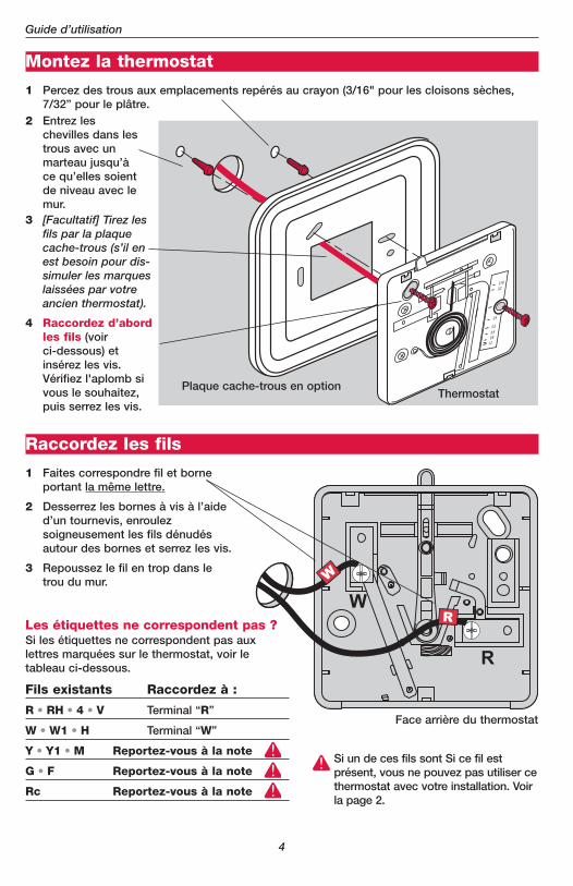
Raccordez les fils
1 Faites correspondre fil et borneportant la même lettre.
2 Desserrez les bornes à vis à l’aided’un tournevis, enroulezsoigneusement les fils dénudésautour des bornes et serrez les vis.
3 Repoussez le fil en trop dans letrou du mur.
Montez la thermostat
1 Percez des trous aux emplacements repérés au crayon (3/16" pour les cloisons sèches,7/32” pour le plâtre.
2 Entrez leschevilles dans lestrous avec unmarteau jusqu’àce qu’elles soientde niveau avec lemur.
3 [Facultatif] Tirez lesfils par la plaquecache-trous (s’il enest besoin pour dis-simuler les marqueslaissées par votreancien thermostat).
4 Raccordez d’abordles fils (voir ci-dessous) etinsérez les vis.Vérifiez l'aplomb sivous le souhaitez,puis serrez les vis.
ThermostatPlaque cache-trous en option
Face arrière du thermostat
Fils existants Raccordez à :
R • RH • 4 • V Terminal “R”
W • W1 • H Terminal “W”
Y • Y1 • M Reportez-vous à la note
G • F Reportez-vous à la note
Rc Reportez-vous à la note
Si un de ces fils sont Si ce fil estprésent, vous ne pouvez pas utiliser cethermostat avec votre installation. Voirla page 2.
Les étiquettes ne correspondent pas ?Si les étiquettes ne correspondent pas aux lettres marquées sur le thermostat, voir letableau ci-dessous.
4
Thermostat basse tension CT30/CT33
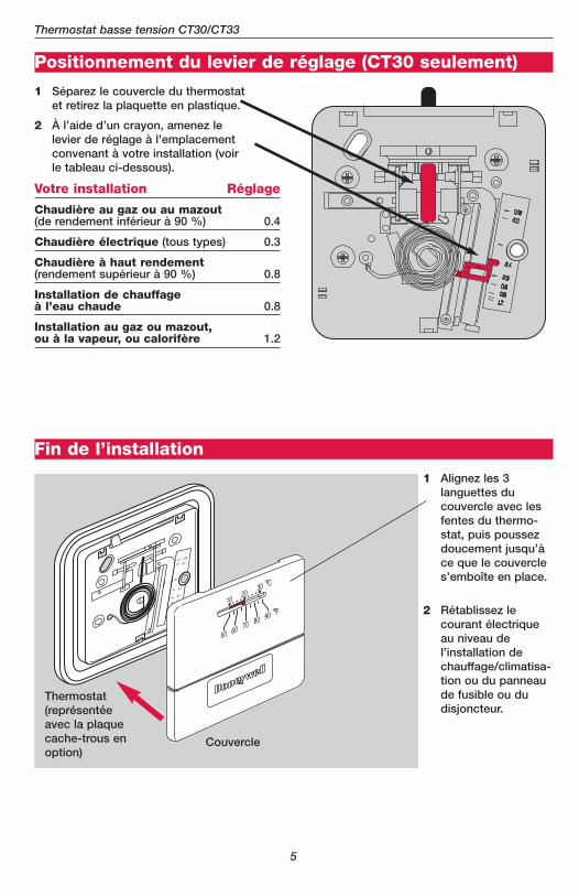
Positionnement du levier de réglage (CT30 seulement)
1 Séparez le couvercle du thermostatet retirez la plaquette en plastique.
2 À l’aide d’un crayon, amenez lelevier de réglage à l'emplacementconvenant à votre installation (voirle tableau ci-dessous).
Votre installation Réglage
Chaudière au gaz ou au mazout(de rendement inférieur à 90 %) 0.4
Chaudière électrique (tous types) 0.3
Chaudière à haut rendement(rendement supérieur à 90 %) 0.8
Installation de chauffage à l’eau chaude 0.8
Installation au gaz ou mazout, ou à la vapeur, ou calorifère 1.2
Fin de l’installation
1 Alignez les 3languettes du couvercle avec lesfentes du thermo-stat, puis poussezdoucement jusqu’àce que le couvercles’emboîte en place.
Couvercle
Thermostat(représentéeavec la plaquecache-trous enoption)
2 Rétablissez lecourant électriqueau niveau de l’installation dechauffage/climatisa-tion ou du panneaude fusible ou du disjoncteur.
5
Guide d’utilisation
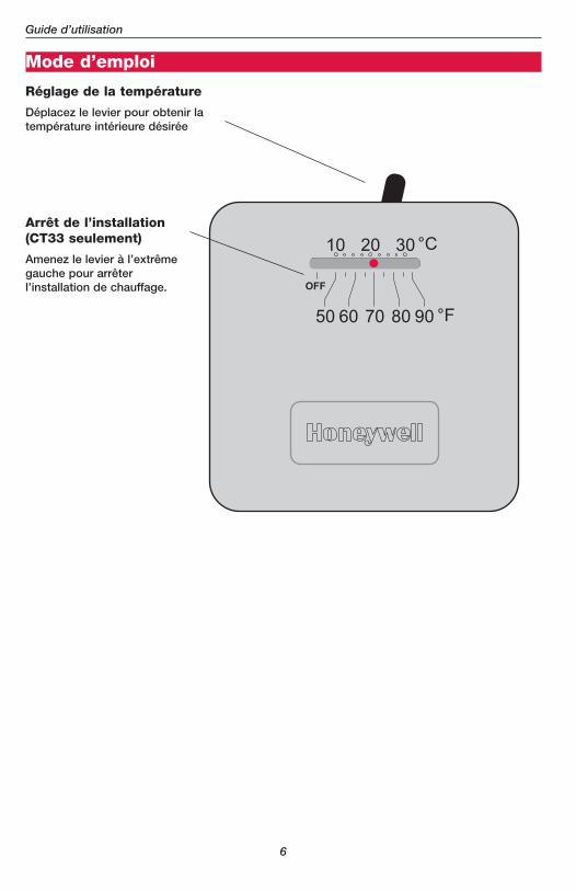
Mode d’emploi
Réglage de la température
Déplacez le levier pour obtenir latempérature intérieure désirée
Arrêt de l’installation(CT33 seulement)
Amenez le levier à l’extrêmegauche pour arrêter l’installation de chauffage.
6
Thermostat basse tension CT30/CT33
Garantie limitée
Honeywell garantit ce produit contre tout vis de fabrication ou de matière dansdes conditions d’utilisation et de service normales, pendant une durée d’un (1) anà compter de la date d’achat par le consommateur. Si à un moment quelconquependant la durée de la garantie, le produit est jugé défectueux ou tombe enpanne, Honeywell le réparera ou le remplacera (au choix d’Honeywell).
Si le produit est défectueux,
(i) retournez-le avec un reçu ou une autre preuve d’achat au lieu où vous l’avezacheté, ou
(ii) appelez le service clients d’Honeywell au 1-800-468-1502. Le service clientsdécidera si le produit doit être renvoyé à l’adresse suivante : Honeywell ReturnGoods, Dock 4 MN10-3860, 1885 Douglas Dr. N., Golden Valley, MN 55422, ou si unproduit de remplacement peut vous être envoyé.
Cette garantie ne couvre pas les frais de démontage ou de réinstallation. Elle nes’applique pas si Honeywell prouve que le défaut ou la défaillance provient dedommages qui se sont produits pendant que le produit était dans la possessiond’un acquéreur.
La responsabilité d’Honeywell se limite à la réparation ou au remplacement duproduit dans les conditions énoncées ci-dessus. HONEYWELL NE SAURAIT ÊTRERESPONSABLE D'UNE PERTE OU DE DOMMAGES QUELS QU'ILS SOIENT,Y COM-PRIS LES DOMMAGES CONSÉCUTIFS OU ACCESSOIRES PROVENANT DIRECTE-MENT OU INDIRECTEMENT D'UNE INFRACTION À LA GARANTIE, EXPLICITEOU IMPLICITE OU DE TOUTE AUTRE DÉFAILLANCE DE CE PRODUIT. Certainsétats ne permettent pas de limites sur la durée d’une garantie implicite, il se peutdonc que les limites ci-dessus ne s’appliquent pas à vous.
CETTE GARANTIE EST LA SEULE GARANTIE EXPLICITE QUE FAIT HONEYWELLSUR CE PRODUIT. LA DURÉE DE TOUTES LES GARANTIES IMPLICITES,Y COM-PRIS CELLES DE QUALITÉ MARCHANDE ET D’ADAPTATION À UN USAGE PARTI-CULIER EST LIMITÉE PAR LA DURÉE D’UN AN DE CETTE GARANTIE. Certainsétats ne permettent pas de limites sur la durée d’une garantie implicite, il se peutdonc que les limites ci-dessus ne s’appliquent pas à vous.
Cette garantie vous donne des droits spécifiques face à la loi et vous pouvez enavoir d’autres, variables d’un état à un autre.
Si vous avez des questions concernant cette garantie, écrivez à HoneywellCustomer Relations, 1985 Douglas Dr, Golden Valley, MN 55422 ou appelez 1-800-468-1502.Au Canada, écrivez à Retail Products ON15-02H, HoneywellLimited/Honeywell Limitée, 35 Dynamic Drive, Scarborough, Ontario M1V4Z9.
7
Honeywell International Inc.
1985 Douglas Drive North
Golden Valley, MN 55422
www.honeywell.com/yourhome
Automation and Control Solutions
Imprimé aux États-Unis sur du papierrecyclé contenant au moins 10% de fibresde papier récupérées après usage.
® U.S. Marque déposée. © 2005 Honeywell International Inc.Brevets en instance. Tous droits réservés.69-1808EF Rev. 03-2005
Honeywell Limited-Honeywell Limitée
35 Dynamic Drive
Scarborough, Ontario M1V 4Z9
Vous faut-il de l’aide ?Pour obtenir de l’assistance concernant ce produit, visitez www.honeywell.com/yourhome
ou appelez gratuitement l’assistance client d’Honeywell au 1-800-468-1502