csric indoor test plan
TRANSCRIPT
The Communications Security, Reliability and Interoperability Council III Working Group 3 “Indoor Location Test Plan”
1
September 21, 2012 WORKING GROUP 3
E9-1-1 Location Accuracy
Indoor Location Test Plan
The Communications Security, Reliability and Interoperability Council III Working Group 3 “Indoor Location Test Plan”
2
Summary
Upon request from CSRIC WG3 a document entitled “Test Plan Input for a Location Technology Test
Bed” was submitted by ESIF to WG3, which provided ESIF’s recommendations for indoor test scenarios
that could be used in Stage 1 of the indoor Test Bed in the San Francisco Bay Area. The technical
approach and methodology recommended by ESIF were accepted by CSRIC WG3. However, bearing in
mind the strict time and budgetary constraints faced by this CSRIC, WG3 created a scaled back version of
the set of test cases cited in the referenced ESIF document. The goal has been to arrive at a smaller
sample of test cases that still provided a good representation of the range of indoor operational
environments across all the morphologies, ranging from dense urban, to urban, to suburban, and rural.
Those test cases were documented in an addendum to the ESIF test plan.
CSRIC WG3’s Indoor Location Test Plan consists of the combination of the ESIF Test Plan and the
Addendum prepared by WG3, both of these components are provided here in this document.

The Communications Security, Reliability and Interoperability Council III Working Group 3 “Indoor Location Test Plan”
3
Committee Name: ESIF ESM
Meeting Location: Virtual
Meeting Date: June 6, 2012
DOCUMENT TYPE – DRAFT BASELINE
TITLE: Draft Baseline for ESIF Issue 77, Test Plan Input for a Location Technology Test Bed
SOURCE*: Susan Sherwood, Verizon Wireless
ISSUE NUMBER: 77
_______________________________
ABSTRACT
This document contains the draft baseline for ESIF Issue 77,
Test Plan Input for a Location Technology Test Bed.
_______________________________

The Communications Security, Reliability and Interoperability Council III Working Group 3 “Indoor Location Test Plan”
4
Contents1. Introduction .......................................................................................................................................... 5
2. Recommendations on Establishing test scenarios & locations ............................................................. 5
3. Scope of Representative Indoor Testing Per Morphology .................................................................. 10
4. Ground Truth Determination .............................................................................................................. 15
5. Data Analysis ....................................................................................................................................... 17

The Communications Security, Reliability and Interoperability Council III Working Group 3 “Indoor Location Test Plan”
5
Introduction The Emergency Services Interconnection Forum (ESIF), in support of The Communications Security, Reliability and Interoperability Council (CSRIC) has identified the need for industry accepted methodologies for testing the accuracy performance of Wireless E9‐1‐1 Phase 2 location systems in “Indoor” environments. Basic requirements for accuracy testing methodologies were addressed in ATIS Standard ATIS‐0500001, released in May of 2004 (updated November 2011), and end‐to‐end functional testing requirements were addressed in ATIS Standard ATIS‐0500009, released in June 2006. Furthermore, ATIS‐0500013 described in detail approaches and methodologies to wireless E‐911 indoor location performance testing.
The present document is intended to leverage these earlier standards and accepted methodologies, in particular ATIS‐0500013, to provide a broad, baseline test plan document for use in comparative indoor location accuracy testing, such as that being considered within CSRIC III, Working Group 3.
This document neither recommends nor imposes a specific test methodology, but rather provides a common frame of reference that individual stakeholders can use to model their tests on so as to guarantee compliance with industry accepted methodology and proper scientific rigor. Every possible effort has been made to ensure that these requirements remain technology neutral.
Per current ESIF Operating Guidelines, due process has been followed in the creation of this document, and development has been open for participation within the bounds of ESIF.
RecommendationsonEstablishingtestscenarios&locations
Section 5 of ATIS‐500013 describes a framework and process for designing a field test that characterizes
indoor performance in the various environments prevailing in a target area, such as the area of the test
bed being proposed by CSRIC III WG3. The approach in this framework is via testing in representative
scenarios and test cases in each distinct environment.
ATIS‐0500011 provides a description of what is typically meant by wireless use environments (or
morphologies). These are classifications that aim to categorize the somewhat distinct characteristics
that a location system, and its underlying wireless network, would have to contend with in attempting
to locate an E911 caller. Certain factors are important in determining the environment in the context of
indoor performance testing: sky visibility, building height, building construction type and material,
density of neighboring buildings, as well as cell site densities and their relative geometries. Still, four
broad environment/morphology classifications could be identified as a start in the target test area, and
those are the familiar dense urban, urban, suburban and rural.
Not all areas across the US will have the same or even similar indoor environments, and often times,
cities in the western US will have different predominant morphologies than others in the Eastern US or
in the Midwest. The same could be said of relatively newer cities or suburban sprawls versus older
denser settlements. However, what matters is that the morphologies prevailing in the test bed area be
adequately present in the representative test scenarios selected.

The Communications Security, Reliability and Interoperability Council III Working Group 3 “Indoor Location Test Plan”
6
One convenient approach to determining the prevailing environments and scenarios in a given area is to
use commercial satellite/aerial imagery tools now widely available in desktop setting. One example is
Google Earth, another is Microsoft Bing. It is recommended that the overall test bed area be examined
first through one of these tools to determine candidate boundaries or polygons where certain distinct
morphologies exist.
The indoor testing framework described in ATIS‐0500013 is illustrated in Figure 5‐1. A given
environment or morphology (e.g., suburban environment) within the test bed area will have a number
of representative scenarios (e.g., 2‐3 story multi‐family apartments as a scenario), and each scenario will
have a few key test cases (e.g., first floor, outside room), then each test case will have a number of
representative test points. These points could be across a number of similar buildings. Finally, at each
test point a number of test calls will be placed. This logical flow down is shown in Figure 5‐1. It is
recommended that this consensus approach be adopted as a framework for the test bed being
proposed by CSRIC WG3.
Figure 5‐1: Scenario and Test Point Definition Flow‐down
ATIS‐0500013 provides as examples recommended test scenarios across the environments observed in
two distinct major cities, namely, Los Angeles and Chicago. Additionally specific pictorial examples of
those scenarios are provided in Annex B of that document. For the purposes of the test bed being
proposed by CSRIC WG3 the following test scenarios are recommended:
Test scenarios in suburban environments:
A. Residential locations:
a. 1‐Story (single family – wood with Stucco; brick where available)
b. 1‐3 story (multi‐family)
c. Multi‐Story
B. Commercial locations:
a. 1‐2 story (retail, business, warehouse, entertainment – wood framing or steel framing
with wood)
b. Multi‐story (professional buildings, medical centers, major malls)
Environment/ Morphology
Scenario Test Case(Sub-Scenario)
Test Points(Locations)
Test Calls
e.g., Suburbane.g., 2-3 Story Multi-familyApartments
e.g., First Floor, Outside Room
e.g., In Apartment Buildings A, B, C
e.g., Calls 1 to 3 or 1 to N at
Each Test Point
Environment/ Morphology
Scenario Test Case(Sub-Scenario)
Test Points(Locations)
Test Calls
e.g., Suburbane.g., 2-3 Story Multi-familyApartments
e.g., First Floor, Outside Room
e.g., In Apartment Buildings A, B, C
e.g., Calls 1 to 3 or 1 to N at
Each Test Point

The Communications Security, Reliability and Interoperability Council III Working Group 3 “Indoor Location Test Plan”
7
Test scenarios in urban and/or dense urban environments:
A. Residential locations
a. 1‐Story (single family – wood; brick or brick façade where available)
b. 1‐3 story (multi‐family – wood; brick or brick façade where available—in dense setting)
c. Multi‐Story (brick or brick façade with steel framing)
B. Commercial locations:
a. 1‐2 story (commercial – masonry/brick)
b. Multi‐story (masonry with steel framing)
c. Many story (commercial sky scraper – steel framing with glass and other materials)
d. Convention hall or center
e. Arena (e.g., for sports)
f. Airport terminal (if logistically possible)
Test scenarios in rural or sparse environments:
A. Residential locations:
a. 1‐Story (single family – wood with Stucco; brick where available)
B. Commercial locations:
a. 1‐2 story (retail, warehouse, barn – wood framing or steel framing with wood)
Each test scenario selected should receive adequate statistical representation in the overall sample of
scenarios. Since buildings of the same type will vary in their specific design, interior space, specific
construction and surroundings, sky visibility, as well as their distance and relative position to
surrounding cell sites, multiple buildings should be selected for each building type in the test area. It is
recommended that a minimum of three buildings be included in each scenario to allow for the capture
of the natural variation in any given scenario type, e.g., 2‐3 story apartment buildings, across the area
under test. Different cell site densities or geometries within a given environment (e.g., suburban)
should be reflected in the building selection whenever possible. In each selected building a number of
test cases should be identified as applicable.
Since for in indoor testing a fair amount of effort would typically go into identifying a candidate building
during pre‐planning and in verifying, in the field, that it is indeed accessible and useable, more than one
indoor test case or test point should be planned per building. This would leverage the pre‐planning and
ground truth determination effort around that structure and enhance the efficiency of resource
utilization.
The recommended number of indoor test cases or test points per structure will typically be in the 2‐6
range, depending on the type and size of structure, and the desire to sample distinct test cases within a
given scenario. This number could vary with the difficulty in determining ground truth for each test case
or test point.
The Communications Security, Reliability and Interoperability Council III Working Group 3 “Indoor Location Test Plan”
8
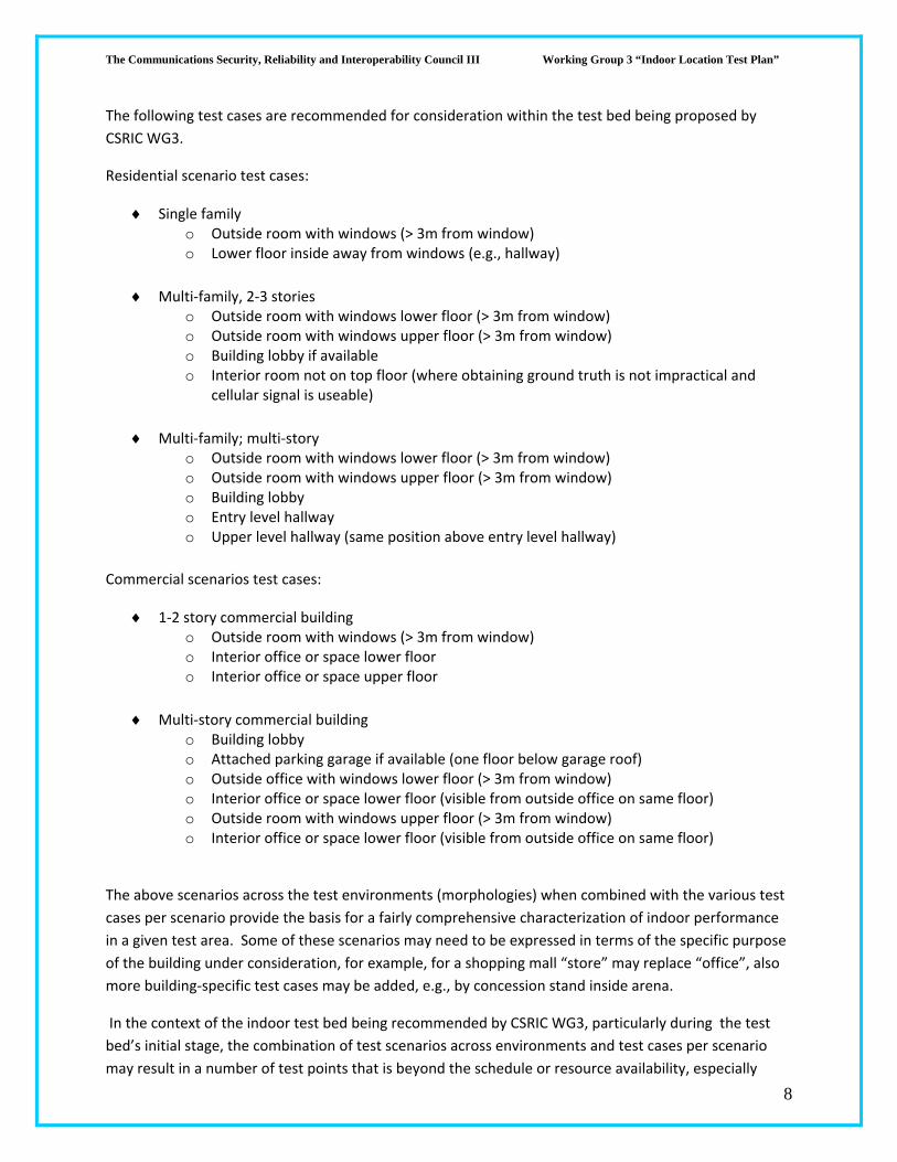
The following test cases are recommended for consideration within the test bed being proposed by
CSRIC WG3.
Residential scenario test cases:
Single family o Outside room with windows (> 3m from window) o Lower floor inside away from windows (e.g., hallway)
Multi‐family, 2‐3 stories o Outside room with windows lower floor (> 3m from window) o Outside room with windows upper floor (> 3m from window) o Building lobby if available o Interior room not on top floor (where obtaining ground truth is not impractical and
cellular signal is useable)
Multi‐family; multi‐story o Outside room with windows lower floor (> 3m from window) o Outside room with windows upper floor (> 3m from window) o Building lobby o Entry level hallway o Upper level hallway (same position above entry level hallway)
Commercial scenarios test cases:
1‐2 story commercial building o Outside room with windows (> 3m from window) o Interior office or space lower floor o Interior office or space upper floor
Multi‐story commercial building o Building lobby o Attached parking garage if available (one floor below garage roof) o Outside office with windows lower floor (> 3m from window) o Interior office or space lower floor (visible from outside office on same floor) o Outside room with windows upper floor (> 3m from window) o Interior office or space lower floor (visible from outside office on same floor)
The above scenarios across the test environments (morphologies) when combined with the various test
cases per scenario provide the basis for a fairly comprehensive characterization of indoor performance
in a given test area. Some of these scenarios may need to be expressed in terms of the specific purpose
of the building under consideration, for example, for a shopping mall “store” may replace “office”, also
more building‐specific test cases may be added, e.g., by concession stand inside arena.
In the context of the indoor test bed being recommended by CSRIC WG3, particularly during the test
bed’s initial stage, the combination of test scenarios across environments and test cases per scenario
may result in a number of test points that is beyond the schedule or resource availability, especially

The Communications Security, Reliability and Interoperability Council III Working Group 3 “Indoor Location Test Plan”
9
when considering that multiple location technologies will have to be evaluated, either simultaneously or
sequentially. With that in mind, the task for the CSRIC working group is to select the highest priority test
scenarios and corresponding test cases. Such prioritization should reflect the specific objectives of the
stage of testing being planned. It is beyond the scope of the current recommendations from ESIF.
One issue that can arise in the test planning process is access to certain types of buildings, in particular,
some residential properties. Indoor residential scenarios, although potentially more cumbersome to
test, are critical to capture and represent as there is an increasing trend for exclusive reliance on
wireless communications in residential settings.
A simple approach that could be taken during test planning to assist with indoor testing is to take
advantage of the buildings of opportunity that present themselves to the organizations executing the
testing. For examples, some houses or apartments where engineers, technicians or administrative staff
members of these organizations live could be included when those individuals are amenable to utilizing
their properties. Care should be taken to avoid using structures of potential convenience to some
technicians that would tend to bias the results, either for better or worse, because they are part of the
wireless network itself, e.g., switch buildings, cell site buildings, etc. RF coverage and location
performance in these setting are non‐typical of the wireless environment at large.
A fall back approach to ensure adequate scenario representation when it is otherwise not possible due
to access constraints, is to include what could be considered “physically equivalent” buildings. These
would be buildings with similar size, construction, density and general sky visibility as those inaccessible.
For example, a hotel could be used in certain cases to simulate an apartment building, a motel to
simulate a 1‐3 story apartment building, a free standing single story business to simulate a house. Due
to the added uncertainties in such simulation, it should only be attempted as a last resort.
In test point selection within each test case and scenario, such as in the test cases identified above, the
initial selection of the test points should avoid situations where it is likely that the wireless signal be very
unreliable or the wireless service only sporadically available. At times, these are situations where there
is access to wireline telephony as the prevalent mode of communication, e.g., in an underground floor
of a business building. Such a situation would not be representative of typical or common wireless
usage anyway.
In each test scenario, and possibly in each test point as needed, the test planner should identify the
appropriate combination of ground truth determination methods to use among those described in ATIS‐
0500013 Section 7 and Annex A. These will likely vary with the scenario, but could well be common
among various test points and scenarios.
Ground truth error should be no more than 10% of overall location error; however, given today’s
location systems’ performance, a five meter ground truth error is an acceptable lower bound with 30
meters as the upper bound. A target ground truth error is 10 meters or less. Measurements from
multiple methods may need to be combined to produce a better result that is consistent with these
requirements.

The Communications Security, Reliability and Interoperability Council III Working Group 3 “Indoor Location Test Plan”
10
Due to the potentially large variation in performance of a wireless device at a certain indoor point, even
with the same location technology, a fairly large sample of independent test calls should be used at each
test point. Based on experience with indoor location systems, a sample of 100 independent test calls
should be used at each test point. In some benign indoor test cases this sample size of 100 calls may
appear to be excessive, but in other cases, which are hard to predict, that sample size will be absolutely
necessary to reliably establish statistical performance of location determination at that test point.
Although statistical aggregation can in principle be performed using a combination of multiple
independent test calls placed at one test point and independent test calls at another similar test point,
i.e., belonging to the same test case (e.g., 2‐3 story apartment building, first floor, outside room), this
should be approached with caution to ensure behavioral similarity, especially across buildings. It is not
advisable that a smaller number of independent test calls be placed at each such test point then relying
on aggregation across test points to create the adequately large statistical sample.
Care must be exercised during testing to ensure that initial conditions are properly reset between the
test calls. ATIS‐0500001 provides the guidelines for these requirements. For example, for AGPS based
location systems, it is required that a hot start not be used. A warm start (with previous location
information deleted and ephemeris data obtained during the current test call) is the recommended test
configuration.
It is also recommended that with any location system under test for indoor operation, the test calls not
make use of location related information derived while initially outdoors.
ScopeofRepresentativeIndoorTestingPerMorphology
This section provides a specific application of the methodology described in the previous sections to
proffer a guiding illustration of the scope of representative indoor testing in an area that contains the
full set of environments (or morphologies) ranging from dense urban to rural or sparse.
The division of test cases follows the flow down logic for test point definition shown above in Figure xx‐
1. The template for this logical division is shown below.
MorphologySetting/Use type
Building Category
Building type
Test case
Test point (if applicable) in some cases more than one test point per test case
may be appropriate as on different sides of a big building
The primary division into morphologies, i.e., by dense urban, urban, suburban, and rural/sparse, mirrors
the variation of the environment by structural density, which clearly impacts indoor wireless location
performance. At the same time, it mirrors and implicitly reflects the variation with wireless
infrastructure cell site density. It is therefore anticipated that variation of wireless location performance

The Communications Security, Reliability and Interoperability Council III Working Group 3 “Indoor Location Test Plan”
11
be observed as the testing is performed across these morphologies. The extent and nature of
performance variation will, naturally, depend on the specific positioning methods used in the
technologies or solutions tested.
Two factors were taken into account in building the “matrix” below, to ensure adequate statistical
representation of the variable world of indoor wireless use. First, for each building type, in each
morphology (i.e., in a given density), a minimum of three buildings are specified. This is to capture the
natural variation in architecture/build and materials used. Second, for each building a number of test
cases is provided that reflect anticipated range of performance variation, and which take advantage of
the initial effort of identifying a suitable building, accessing it, and expending the resources to go about
determining the ground truths inside and about that building.
In some test cases, it may be appropriate to define more than one test point that pertain to a certain
test case, for example, an outside room on the lower level of a big building, but with one test point on
each of two sides of the building. This could be to reflect different prevailing sky or cell site visibility
conditions. Such level of granularity is not included here and is left to whoever is selecting the specific
test points to decide on. In general, the majority of test cases in a building will contain only one test
point, and that’s the level used in the “matrix” below.
For each test point, it is assumed that a sufficient number of independent test calls are placed from one
or more nearly co‐located devices per technology. For the purposes of the CSRIC Test the following are
considered the minimum test cases that need to be conducted (a more complete list is attached in
Appendix A)

The Communications Security, Reliability and Interoperability Council III Working Group 3 “Indoor Location Test Plan”
12
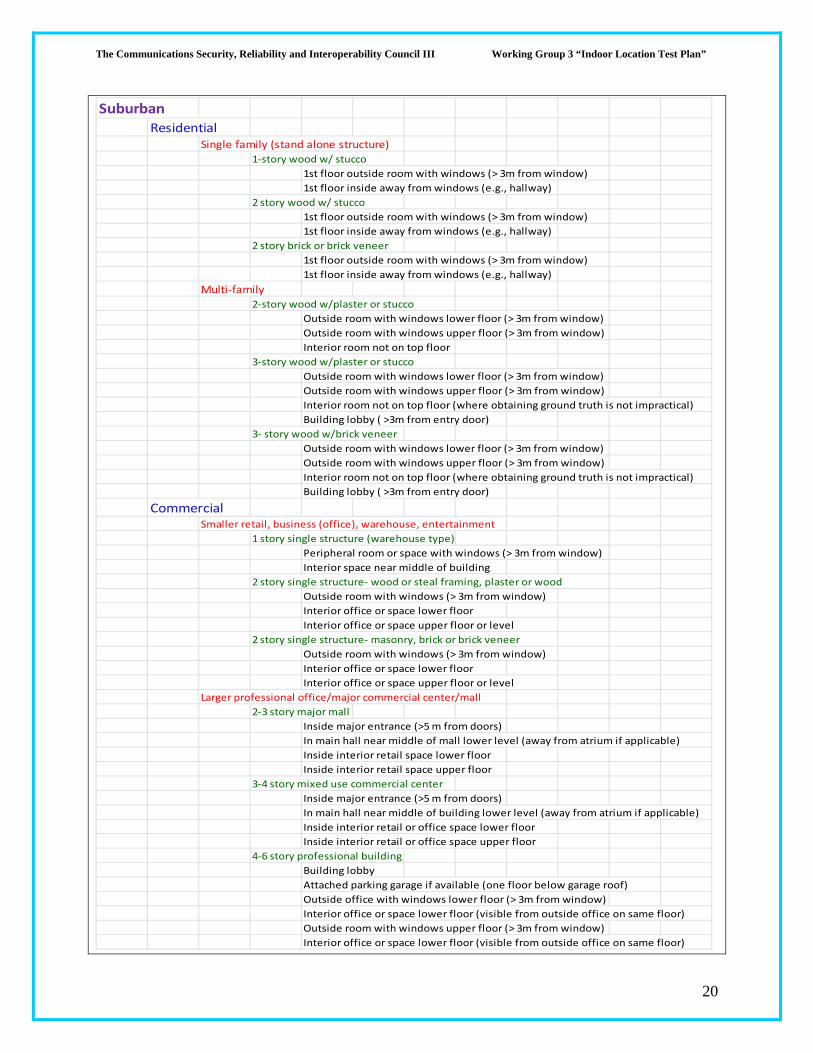
SuburbanResidential
Single family (stand alone structure)
1‐story wood w/ stucco
1st floor outside room with windows (> 3m from window)
1st floor inside away from windows (e.g., hallway)
2 story brick or brick veneer
1st floor outside room with windows (> 3m from window)
1st floor inside away from windows (e.g., hallway)
Multi‐family
3‐story wood w/plaster or stucco
Outside room with windows lower floor (> 3m from window)
Outside room with windows upper floor (> 3m from window)
Interior room not on top floor (where obtaining ground truth is not impractical)
Building lobby ( >3m from entry door)
CommercialSmaller retail, business (office), warehouse, entertainment
2 story single structure‐ wood or steel framing, plaster or wood
Outside room with windows (> 3m from window)
Interior office or space lower floor
Interior office or space upper floor or level
Larger professional office/major commercial center/mall
2‐3 story major mall
Inside major entrance (>5 m from doors)
In main hall near middle of mall lower level (away from atrium if applicable)
Inside interior retail space lower floor
Inside interior retail space upper floor
4‐6 story professional building
Building lobby
Attached parking garage if available (one floor below garage roof)
Outside office with windows lower floor (> 3m from window)
Interior office or space lower floor (visible from outside office on same floor)
Outside room with windows upper floor (> 3m from window)
Interior office or space lower floor (visible from outside office on same floor)
The Communications Security, Reliability and Interoperability Council III Working Group 3 “Indoor Location Test Plan”
13
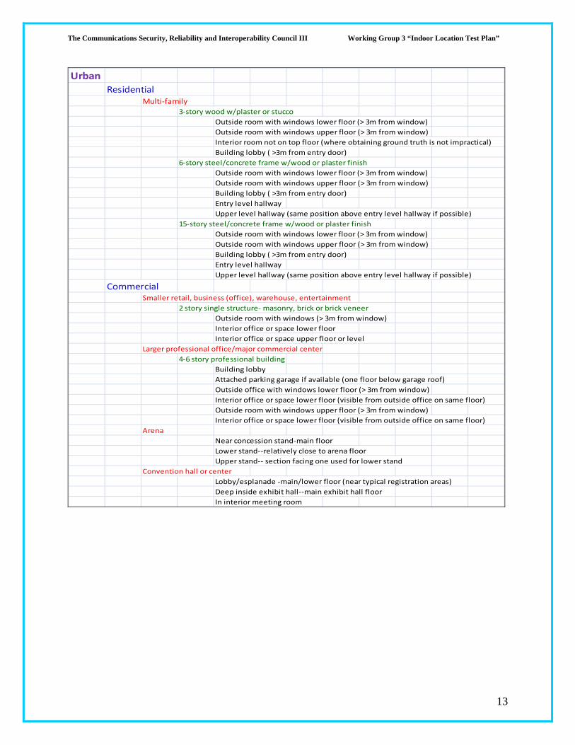
UrbanResidential
Multi‐family
3‐story wood w/plaster or stucco
Outside room with windows lower floor (> 3m from window)
Outside room with windows upper floor (> 3m from window)
Interior room not on top floor (where obtaining ground truth is not impractical)
Building lobby ( >3m from entry door)
6‐story steel/concrete frame w/wood or plaster finish
Outside room with windows lower floor (> 3m from window)
Outside room with windows upper floor (> 3m from window)
Building lobby ( >3m from entry door)
Entry level hallway
Upper level hallway (same position above entry level hallway if possible)
15‐story steel/concrete frame w/wood or plaster finish
Outside room with windows lower floor (> 3m from window)
Outside room with windows upper floor (> 3m from window)
Building lobby ( >3m from entry door)
Entry level hallway
Upper level hallway (same position above entry level hallway if possible)
CommercialSmaller retail, business (office), warehouse, entertainment
2 story single structure‐ masonry, brick or brick veneer
Outside room with windows (> 3m from window)
Interior office or space lower floor
Interior office or space upper floor or level
Larger professional office/major commercial center
4‐6 story professional building
Building lobby
Attached parking garage if available (one floor below garage roof)
Outside office with windows lower floor (> 3m from window)
Interior office or space lower floor (visible from outside office on same floor)
Outside room with windows upper floor (> 3m from window)
Interior office or space lower floor (visible from outside office on same floor)
Arena
Near concession stand‐main floor
Lower stand‐‐relatively close to arena floor
Upper stand‐‐ section facing one used for lower stand
Convention hall or center
Lobby/esplanade ‐main/lower floor (near typical registration areas)
Deep inside exhibit hall‐‐main exhibit hall floor
In interior meeting room
The Communications Security, Reliability and Interoperability Council III Working Group 3 “Indoor Location Test Plan”
14
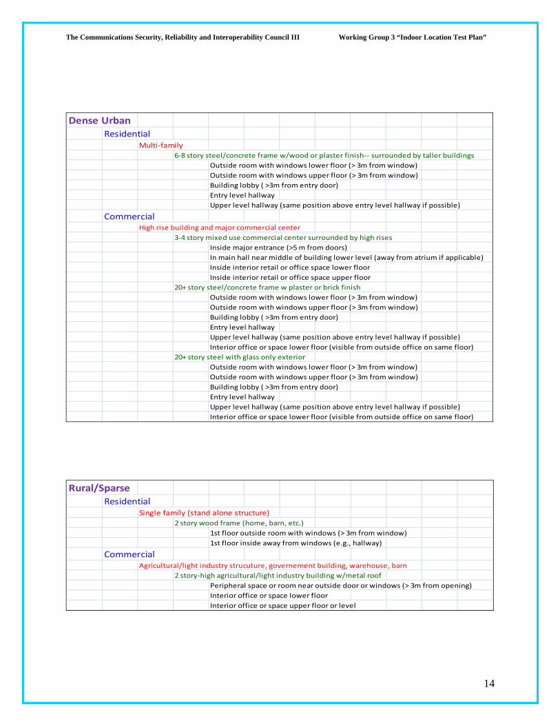
Dense UrbanResidential
Multi‐family6‐8 story steel/concrete frame w/wood or plaster finish‐‐ surrounded by taller buildings
Outside room with windows lower floor (> 3m from window)
Outside room with windows upper floor (> 3m from window)
Building lobby ( >3m from entry door)
Entry level hallway
Upper level hallway (same position above entry level hallway if possible)
CommercialHigh rise building and major commercial center
3‐4 story mixed use commercial center surrounded by high rises
Inside major entrance (>5 m from doors)
In main hall near middle of building lower level (away from atrium if applicable)
Inside interior retail or office space lower floor
Inside interior retail or office space upper floor
20+ story steel/concrete frame w plaster or brick finish
Outside room with windows lower floor (> 3m from window)
Outside room with windows upper floor (> 3m from window)
Building lobby ( >3m from entry door)
Entry level hallway
Upper level hallway (same position above entry level hallway if possible)
Interior office or space lower floor (visible from outside office on same floor)
20+ story steel with glass only exterior
Outside room with windows lower floor (> 3m from window)
Outside room with windows upper floor (> 3m from window)
Building lobby ( >3m from entry door)
Entry level hallway
Upper level hallway (same position above entry level hallway if possible)
Interior office or space lower floor (visible from outside office on same floor)
Rural/SparseResidential
Single family (stand alone structure)
2 story wood frame (home, barn, etc.)
1st floor outside room with windows (> 3m from window)
1st floor inside away from windows (e.g., hallway)
CommercialAgricultural/light industry strucuture, governement building, warehouse, barn
2 story‐high agricultural/light industry building w/metal roof
Peripheral space or room near outside door or windows (> 3m from opening)
Interior office or space lower floor
Interior office or space upper floor or level

The Communications Security, Reliability and Interoperability Council III Working Group 3 “Indoor Location Test Plan”
15
Once the specific buildings are determined following the above guideline, the estimation of effort
follows a multiplication process for two major tasks that could be done sequentially in two separate
steps, or at the same time. These tasks are: (1) identification of each specific test point and determining
it ground truth, and (2) setting up the test equipment and placing the test calls from the devices under
test at each of these test points. Performing the two steps at the same time could be more efficient
depending on the resources used.
Estimating the time for ground truth determination is more subject to engineering judgment, the
specifics of each building, and the desired level of assuredness by selecting among the options of ground
truth determination described in Section 7 of ATIS‐0500013. Estimating the scope of effort for the task
of performing the test calls at the test points is more straight‐forward.
For the purposes of this test it can be assumed that 3 “test handsets” are available for placing test calls
simultaneously at each test point. It is also assumed that a minimum of 100 independent test calls are
required at each test point from each technology under test. This means that the assumed set of
essentially co‐located 3 “tests handsets” will place at least 100 valid test calls in aggregate. To allow for
a few failed calls, for whatever reason, it can be assumed that 40 test calls are required per device. It is
also reasonable to assume that each test call would last 40‐45 seconds and the remainder of a one
minute be used as a test call pause. Maintaining a 1 minute minimum separation between test calls
from each device simplifies the analysis of the test call data. If there are issues that pertain to location
caching that make a longer pause between individual test calls necessary, this extra delay needs to be
taken into account. It is not included in this illustration.
Accordingly, approximately 40 minutes are allocated to placement of test calls at a test point and
roughly 20 minutes allocated to getting to the test point inside the building, verifying its correctness by
the test crew, documenting it including photography, and setting‐up and taking down the test
equipment.
Hence, a simple building, like a single family residence with two test points would consume two hours.
A complex building like a high rise with six test points would consume approximately 6 hours. In either
case adequate additional time needs to be allocated to transportation to the building being tested and
parking in its vicinity, and to allow for normal crew breaks. Finally, an allowance needs to be made for
contingencies and delays, often outside the control of the test crew, which arise in any field testing.
GroundTruthDetermination
ATIS Standard 0500013, Section 7 contains a detailed description of determining ground truth for indoor
test points and sets a standard for the accuracy required on ground truth measurements. Section 7.2
states that ground truth error should be no more than 10% of overall location error, but should remain
within a lower bound of 5 meter ground truth error and an upper bound of 30 meters, with a target

The Communications Security, Reliability and Interoperability Council III Working Group 3 “Indoor Location Test Plan”
16
ground truth error of ten meters or less. Section 7.2 also points out that measurements from multiple
ground truth methods may need to be combined to produce a ground truth error for an indoor test
point within the acceptable bounds.
Section 7.1 describes multiple approaches for determining ground truth of a given indoor test point.
These methods include:
Surveying Company – Professional surveying is the most costly method, but is likely to produce the most reliable ground truth measurements.
Differential GPS service (DGPS) – This method is most useful in areas where there is a clear view of the sky and minimal GPS signal blockage. This method is less costly than using a surveying company, expedient, and scalable. However, it may yield poor indoor results and requires trained personnel if used. For example, the accuracy of the reported position can have significant unreported errors due to the GPS signals having multipath and related signal noise. The minimum requirement for using a reported GPS position fix as ground truth is five satellites contributing to the calculation. The standard deviation in horizontal error of fixes collected over two minutes should be less than ten meters. In cases of less than the desired accuracy, DGPS can be augmented with other methods such as correlation with digital satellite maps.
Rolling Measuring Wheel ‐ This method may be used in locations where there is significant GPS signal blockage and/or contamination. A rolling measuring wheel can be used to measure the distance from open sky or known reference point to the test site. It results in a higher indoor yield of ground truth and the accuracy is comparable to DGPS ground truth. However, it can be error prone due to a lack of experience, and requires more training than DGPS.
DGPS with Inertial Measurement Units (IMU) – This method requires less training than DGPS or the rolling measure wheel, and is less obtrusive than using a rolling measure wheel. However, it is not widely available on a commercial basis. An Inertial Measurement Unit (IMU) is another method of calculating the offset from a known position outdoors to a position indoors. This technology combines a GPS receiver, magnetic compass, accelerometer and gyroscope in a portable format.
Differentially Corrected Digital Maps – This method is easy to use and implement with training, but can be inconsistent and may have uncertain accuracy. It is dependent on the map reliability and age, the user experience and training, and the map datum and projection. One approach is to combine available overhead satellite images that have been georegistered with a public guide map, such as in a mall. The pitfall to this approach is that there is no stated accuracy on the publicly available mapping web sites. While many are quite good (often ten meters or better accuracy), there are specific areas that can have larger errors. Also, the services continually update their imagery and the georegistration can improve or degrade with each update.
The testing house will be required to select the most appropriate ‘Ground Truth’ determination
technique that allows us to get a Ground Truth within an accuracy of 10m or better. (An appropriately
chosen vertical ground truth will also need to be determined based on the CSRIC committee’s final
recommendation).
The Communications Security, Reliability and Interoperability Council III Working Group 3 “Indoor Location Test Plan”
17
DataAnalysis
ATIS‐0500001, Section 9 and ATIS‐0500013, Section 9 each include valuable guidance on the Data
Analysis phase of accuracy testing. In general, data analysis falls into three high‐level steps: data
validation, data processing, and data evaluation.
Data validation is an important step during which the data is inspected and erroneous data is corrected
or removed from the bucket of valid data. During this process it’s important that data should not be
deleted, but set aside and retrievable for possible further analysis.
ATIS 0500013, Section 9 identifies several types of data analysis that can be performed on collected data
sets to check validity. This analysis checks for common errors, including human errors, incorrect test
execution, and equipment failure. Sections 9.1 through 9.3 outlines three levels of data checking:
1. First level is basic fact checking on quantity of position fixes and coarse alignment. Basic sanity checking may be performed at multiple times during the data collection process. When first setting up on the given test location, check the first result in real time to make sure the system is working. For example, the tester should ensure there is adequate wireless coverage indoors to allow a test call to go through. ATIS 0500001, Section 9 indicates that failed or dropped calls should not be included in the valid test date. In addition, a real time comparison of the test position result with the ground truth location will confirm coarse alignment of test location and that data has been entered correctly by the tester.
2. Second level is a review of the data against the original test objectives. The test planner should examine the data and verify that any variations in accuracy were not the result of test planning or execution. Observed anomalies should be listed and their likely causes identified. Unexplained anomalies should drive a further review of the test process. ATIS 05‐00001, Section 9 states that any identified systematic errors shall be reported as part of the summary and not included in the accuracy data calculation. The processing of outliers (instances of particularly large errors) shall be handled with care due to the potentially large spread of location results in indoor settings.
3. Third level is a comparison against other test results in comparable environments. The test results can be compared to other testing performed in similar environments and any differences can be cause for a review of data collection procedures or external environment for previously unrecognized effects.
Summary test results across all the technologies will need to be determined. This includes:
a. CDF of location results per location and location technology b. Determination of Yield per location and location technology c. Determination of TTFF per location and location technology
Final ‘Data Analysis’ will be specified by the CSRIC committee as part of the agreement between the
testing house and location technology vendor
The Communications Security, Reliability and Interoperability Council III Working Group 3 “Indoor Location Test Plan”
18
ATIS 0500001, Section 9.4 states that sufficient amounts of data shall be collected so that during data
processing, the desired error thresholds are calculated with at least 90% confidence. In addition, all calls
shall be documented and classified clearly .
Due to the nature of sample based testing, results during data evaluation should be reviewed to ensure
the conclusions are representative of the nominal system performance. It should be understood that
the indoor spread of data results is expected to be considerably larger than outdoor results. In addition,
ATIS 0500013, Section 10.2 stresses the importance of reviewing pitfalls identified during the testing
process prior to formalizing and disseminating the test results. These pitfalls include, but not limited to:
data integrity, recognizing the technical limitations of the technology being tested, inconsistent
application of test procedures, and ensuring that the analysis of test results account for the range of
location technologies available to each device.

The Communications Security, Reliability and Interoperability Council III Working Group 3 “Indoor Location Test Plan”
19
AppendixA (Full Matrix of Test Cases)
The Communications Security, Reliability and Interoperability Council III Working Group 3 “Indoor Location Test Plan”
20
SuburbanResidential
Single family (stand alone structure)
1‐story wood w/ stucco
1st floor outside room with windows (> 3m from window)
1st floor inside away from windows (e.g., hallway)
2 story wood w/ stucco
1st floor outside room with windows (> 3m from window)
1st floor inside away from windows (e.g., hallway)
2 story brick or brick veneer
1st floor outside room with windows (> 3m from window)
1st floor inside away from windows (e.g., hallway)
Multi‐family
2‐story wood w/plaster or stucco
Outside room with windows lower floor (> 3m from window)
Outside room with windows upper floor (> 3m from window)
Interior room not on top floor
3‐story wood w/plaster or stucco
Outside room with windows lower floor (> 3m from window)
Outside room with windows upper floor (> 3m from window)
Interior room not on top floor (where obtaining ground truth is not impractical)
Building lobby ( >3m from entry door)
3‐ story wood w/brick veneer
Outside room with windows lower floor (> 3m from window)
Outside room with windows upper floor (> 3m from window)
Interior room not on top floor (where obtaining ground truth is not impractical)
Building lobby ( >3m from entry door)
CommercialSmaller retail, business (office), warehouse, entertainment
1 story single structure (warehouse type)
Peripheral room or space with windows (> 3m from window)
Interior space near middle of building
2 story single structure‐ wood or steal framing, plaster or wood
Outside room with windows (> 3m from window)
Interior office or space lower floor
Interior office or space upper floor or level
2 story single structure‐ masonry, brick or brick veneer
Outside room with windows (> 3m from window)
Interior office or space lower floor
Interior office or space upper floor or level
Larger professional office/major commercial center/mall
2‐3 story major mall
Inside major entrance (>5 m from doors)
In main hall near middle of mall lower level (away from atrium if applicable)
Inside interior retail space lower floor
Inside interior retail space upper floor
3‐4 story mixed use commercial center
Inside major entrance (>5 m from doors)
In main hall near middle of building lower level (away from atrium if applicable)
Inside interior retail or office space lower floor
Inside interior retail or office space upper floor
4‐6 story professional building
Building lobby
Attached parking garage if available (one floor below garage roof)
Outside office with windows lower floor (> 3m from window)
Interior office or space lower floor (visible from outside office on same floor)
Outside room with windows upper floor (> 3m from window)
Interior office or space lower floor (visible from outside office on same floor)

The Communications Security, Reliability and Interoperability Council III Working Group 3 “Indoor Location Test Plan”
21
UrbanResidential
Multi‐family
3‐story wood w/plaster or stucco
Outside room with windows lower floor (> 3m from window)
Outside room with windows upper floor (> 3m from window)
Interior room not on top floor (where obtaining ground truth is not impractical)
Building lobby ( >3m from entry door)
3‐ story wood w/brick veneer
Outside room with windows lower floor (> 3m from window)
Outside room with windows upper floor (> 3m from window)
Interior room not on top floor (where obtaining ground truth is not impractical)
Building lobby ( >3m from entry door)
6‐story steel/concrete frame w/wood or plaster finish
Outside room with windows lower floor (> 3m from window)
Outside room with windows upper floor (> 3m from window)
Building lobby ( >3m from entry door)
Entry level hallway
Upper level hallway (same position above entry level hallway if possible)
15‐story steel/concrete frame w/wood or plaster finish
Outside room with windows lower floor (> 3m from window)
Outside room with windows upper floor (> 3m from window)
Building lobby ( >3m from entry door)
Entry level hallway
Upper level hallway (same position above entry level hallway if possible)
CommercialSmaller retail, business (office), warehouse, entertainment
1 story single structure (warehouse type)
Peripheral room or space with windows (> 3m from window)
Interior space near middle of building
2 story single structure‐ wood or steal framing, plaster or wood
Outside room with windows (> 3m from window)
Interior office or space lower floor
Interior office or space upper floor or level
2 story single structure‐ masonry, brick or brick veneer
Outside room with windows (> 3m from window)
Interior office or space lower floor
Interior office or space upper floor or level
Larger professional office/major commercial center
3‐4 story mixed use commercial center
Inside major entrance (>5 m from doors)
In main hall near middle of building lower level (away from atrium if applicable)
Inside interior retail or office space lower floor
Inside interior retail or office space upper floor
4‐6 story professional building
Building lobby
Attached parking garage if available (one floor below garage roof)
Outside office with windows lower floor (> 3m from window)
Interior office or space lower floor (visible from outside office on same floor)
Outside room with windows upper floor (> 3m from window)
Interior office or space lower floor (visible from outside office on same floor)
15+ story commercial high rise
Building lobby
Attached parking garage if available (one floor below garage roof)
Outside office with windows lower floor (> 3m from window)
Interior office or space lower floor (visible from outside office on same floor)
Outside room with windows upper floor (> 3m from window)
Interior office or space lower floor (visible from outside office on same floor)
Arena
Specific test cases to be developed
Convention hall or center
Specific test cases to be developed
Airport Terminal
Specific test cases to be developed

The Communications Security, Reliability and Interoperability Council III Working Group 3 “Indoor Location Test Plan”
22
Dense UrbanResidential
Multi‐family
6‐8 story steel/concrete frame w/wood or plaster finish‐‐ surrounded by taller buildings
Outside room with windows lower floor (> 3m from window)
Outside room with windows upper floor (> 3m from window)
Building lobby ( >3m from entry door)
Entry level hallway
Upper level hallway (same position above entry level hallway if possible)
6‐8 story steel/concrete frame w/brick or masonary‐‐ surrounded by taller buildings
Outside room with windows lower floor (> 3m from window)
Outside room with windows upper floor (> 3m from window)
Building lobby ( >3m from entry door)
Entry level hallway
Upper level hallway (same position above entry level hallway if possible)
20+ story steel/concrete frame w plaster or brick finish
Outside room with windows lower floor (> 3m from window)
Outside room with windows upper floor (> 3m from window)
Building lobby ( >3m from entry door)
Entry level hallway
Upper level hallway (same position above entry level hallway if possible)
CommercialHigh rise building and major commercial center
3‐4 story mixed use commercial center surrounded by high rises
Inside major entrance (>5 m from doors)
In main hall near middle of building lower level (away from atrium if applicable)
Inside interior retail or office space lower floor
Inside interior retail or office space upper floor
20+ story steel/concrete frame w plaster or brick finish
Outside room with windows lower floor (> 3m from window)
Outside room with windows upper floor (> 3m from window)
Building lobby ( >3m from entry door)
Entry level hallway
Upper level hallway (same position above entry level hallway if possible)
Interior office or space lower floor (visible from outside office on same floor)
20+ story steel with glass only exterior
Outside room with windows lower floor (> 3m from window)
Outside room with windows upper floor (> 3m from window)
Building lobby ( >3m from entry door)
Entry level hallway
Upper level hallway (same position above entry level hallway if possible)
Interior office or space lower floor (visible from outside office on same floor)

The Communications Security, Reliability and Interoperability Council III Working Group 3 “Indoor Location Test Plan”
23
Rural/SparseResidential
Single family (stand alone structure)
1‐story wood (home, barn, work shed)
1st floor outside room with windows (> 3m from window)
1st floor inside away from windows (e.g., hallway)
2 story wood frame (home, barn, etc.)
1st floor outside room with windows (> 3m from window)
1st floor inside away from windows (e.g., hallway)
2 story brick or brick veneer
1st floor outside room with windows (> 3m from window)
1st floor inside away from windows (e.g., hallway)
CommercialAgricultural/light industry strucuture, governement building, warehouse, barn
1 story single structure (warehouse type)
Peripheral room or space with windows (> 3m from window)
Interior space near middle of building
2 story‐high agricultural/light industry building w/metal roof
Peripheral space or room near outside door or windows (> 3m from opening)
Interior office or space lower floor
Interior office or space upper floor or level
2 story building‐ masonry, brick or brick veneer (county gov., courthouse, etc.)
Outside room with windows (> 3m from window)
Interior office or space lower floor
Interior office or space upper floor or level

The Communications Security, Reliability and Interoperability Council III Working Group 3 “Indoor Location Test Plan”
24
Addendum to Test Plan Input for Indoor Testing
August 24, 2012
A document entitled “Test Plan Input for a Location Technology Test Bed” was submitted by ESIF, upon
CSRIC WG3’s request, providing ESIF’s recommendations for indoor test scenarios that could be used in
Stage 1 of the indoor Test Bed to be implemented in the San Francisco Bay Area. This addendum
provides the results of an effort within the CSRIC WG3 to create a scaled back version of the set of test
cases cited in the referenced ESIF document, which could be utilized in the event time or budgetary
constraints preclude the possibility of implementing the full set identified therein.
The goal has been to arrive at a smaller sample of test cases that still provides a good representation of
the range of indoor operational environments across all the morphologies, ranging from dense urban to
rural. Hence, the approach has been to reduce the test cases which have some similarity or those that
are difficult to encounter on the West Coast (e.g., a large brick building). The same overall methodology
and logical breakdown of test cases is followed as in the original ESIF document.
MorphologySetting/Use type
Building Category
Building type
Test case
1 test point per test case (e.g., not doing 2 similar outside rooms on opposite
sides of a given building, which would be 2 test points belonging to 1 test case)
The reduced sample of test cases provided herein is felt to be of the minimum size necessary to capture
the expected environmental variations for indoor wireless use and simultaneously offer adequate
statistical reliability in the results. It should be emphasized, however, that WG3’s preference is to
execute the full set of test cases, or as much of it as feasible, to attain the best statistical robustness in
the results; e.g., to minimize the effects of the selection of specific buildings in the sample.

The Communications Security, Reliability and Interoperability Council III Working Group 3 “Indoor Location Test Plan”
25
SuburbanResidential
Single family (stand alone structure)
1‐story wood w/ stucco
1st floor outside room with windows (> 3m from window)
1st floor inside away from windows (e.g., hallway)
2 story brick or brick veneer
1st floor outside room with windows (> 3m from window)
1st floor inside away from windows (e.g., hallway)
Multi‐family
3‐story wood w/plaster or stucco
Outside room with windows lower floor (> 3m from window)
Outside room with windows upper floor (> 3m from window)
Interior room not on top floor (where obtaining ground truth is not impractical)
Building lobby ( >3m from entry door)
CommercialSmaller retail, business (office), warehouse, entertainment
2 story single structure‐ wood or steel framing, plaster or wood
Outside room with windows (> 3m from window)
Interior office or space lower floor
Interior office or space upper floor or level
Larger professional office/major commercial center/mall
2‐3 story major mall
Inside major entrance (>5 m from doors)
In main hall near middle of mall lower level (away from atrium if applicable)
Inside interior retail space lower floor
Inside interior retail space upper floor
4‐6 story professional building
Building lobby
Attached parking garage if available (one floor below garage roof)
Outside office with windows lower floor (> 3m from window)
Interior office or space lower floor (visible from outside office on same floor)
Outside room with windows upper floor (> 3m from window)
Interior office or space lower floor (visible from outside office on same floor)

The Communications Security, Reliability and Interoperability Council III Working Group 3 “Indoor Location Test Plan”
26
UrbanResidential
Multi‐family
3‐story wood w/plaster or stucco
Outside room with windows lower floor (> 3m from window)
Outside room with windows upper floor (> 3m from window)
Interior room not on top floor (where obtaining ground truth is not impractical)
Building lobby ( >3m from entry door)
6‐story steel/concrete frame w/wood or plaster finish
Outside room with windows lower floor (> 3m from window)
Outside room with windows upper floor (> 3m from window)
Building lobby ( >3m from entry door)
Entry level hallway
Upper level hallway (same position above entry level hallway if possible)
15‐story steel/concrete frame w/wood or plaster finish
Outside room with windows lower floor (> 3m from window)
Outside room with windows upper floor (> 3m from window)
Building lobby ( >3m from entry door)
Entry level hallway
Upper level hallway (same position above entry level hallway if possible)
CommercialSmaller retail, business (office), warehouse, entertainment
2 story single structure‐ masonry, brick or brick veneer
Outside room with windows (> 3m from window)
Interior office or space lower floor
Interior office or space upper floor or level
Larger professional office/major commercial center
4‐6 story professional building
Building lobby
Attached parking garage if available (one floor below garage roof)
Outside office with windows lower floor (> 3m from window)
Interior office or space lower floor (visible from outside office on same floor)
Outside room with windows upper floor (> 3m from window)
Interior office or space lower floor (visible from outside office on same floor)
Arena
Near concession stand‐main floor
Lower stand‐‐relatively close to arena floor
Upper stand‐‐ section facing one used for lower stand
Convention hall or center
Lobby/esplanade ‐main/lower floor (near typical registration areas)
Deep inside exhibit hall‐‐main exhibit hall floor
In interior meeting room
The Communications Security, Reliability and Interoperability Council III Working Group 3 “Indoor Location Test Plan”
27
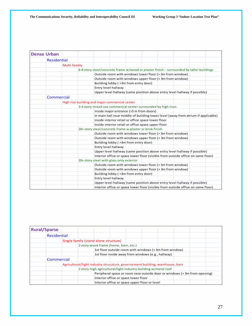
Dense UrbanResidential
Multi‐family
6‐8 story steel/concrete frame w/wood or plaster finish‐‐ surrounded by taller buildings
Outside room with windows lower floor (> 3m from window)
Outside room with windows upper floor (> 3m from window)
Building lobby ( >3m from entry door)
Entry level hallway
Upper level hallway (same position above entry level hallway if possible)
CommercialHigh rise building and major commercial center
3‐4 story mixed use commercial center surrounded by high rises
Inside major entrance (>5 m from doors)
In main hall near middle of building lower level (away from atrium if applicable)
Inside interior retail or office space lower floor
Inside interior retail or office space upper floor
20+ story steel/concrete frame w plaster or brick finish
Outside room with windows lower floor (> 3m from window)
Outside room with windows upper floor (> 3m from window)
Building lobby ( >3m from entry door)
Entry level hallway
Upper level hallway (same position above entry level hallway if possible)
Interior office or space lower floor (visible from outside office on same floor)
20+ story steel with glass only exterior
Outside room with windows lower floor (> 3m from window)
Outside room with windows upper floor (> 3m from window)
Building lobby ( >3m from entry door)
Entry level hallway
Upper level hallway (same position above entry level hallway if possible)
Interior office or space lower floor (visible from outside office on same floor)
Rural/SparseResidential
Single family (stand alone structure)2 story wood frame (home, barn, etc.)
1st floor outside room with windows (> 3m from window)
1st floor inside away from windows (e.g., hallway)
CommercialAgricultural/light industry strucuture, governement building, warehouse, barn
2 story‐high agricultural/light industry building w/metal roof
Peripheral space or room near outside door or windows (> 3m from opening)
Interior office or space lower floor
Interior office or space upper floor or level