csec physics review - introduction to logic gates
TRANSCRIPT

What Are Logic GatesA logic gate is an elementary building block of a digital circuit.
Most logic gates have two inputs and one output. At any given moment, every terminal is in one of two Binary Conditions: Low (0) or High (1), represented by different voltage levels.
The logic state of a terminal can, and generally does, change often, as the circuit processes data. In most logic gates, the low state is approximately zero volts (0 V), while the high state is approximately five volts positive (+5 V).
There are seven basic Logic Gates:
NOT, AND, OR, NAND, NOR, XOR and XNOR
We will look at each of them individually.

The ‘NOT’ Gate• This is the most basic type of
logic gate which only accepts one input.
• The function of this gate is to function as a logical inverter, and hence reverses the logic state of its input.

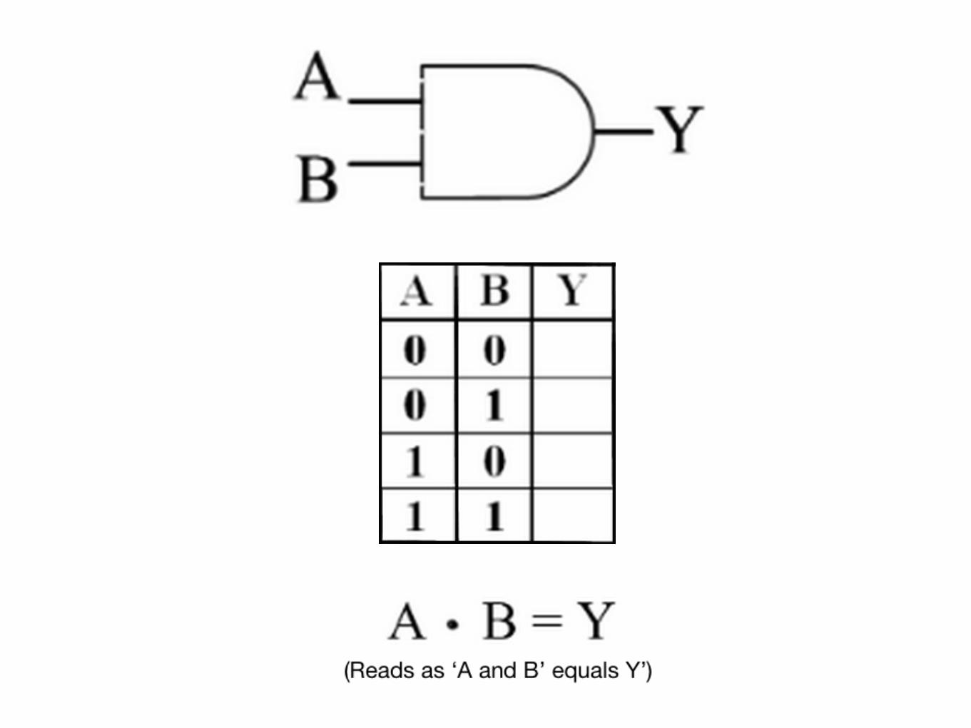
The ‘AND’ GateThis logic gate has two inputs that produces one output. The output is 1 (High) only when both inputs are also high. Otherwise the value for the output is 0 (Low). Below is a table showing the logical combinations for the AND gate:
Input 1 (A) Input 2 (B) Output (Y)
0 0 00 1 01 0 01 1 1

The ‘OR’ Gate• This logic gate also has two
inputs and one output.
• The output is 1 (High) if either or both of the inputs are high.
• The output is 0 (Low) only if both outputs are 0 (Low).

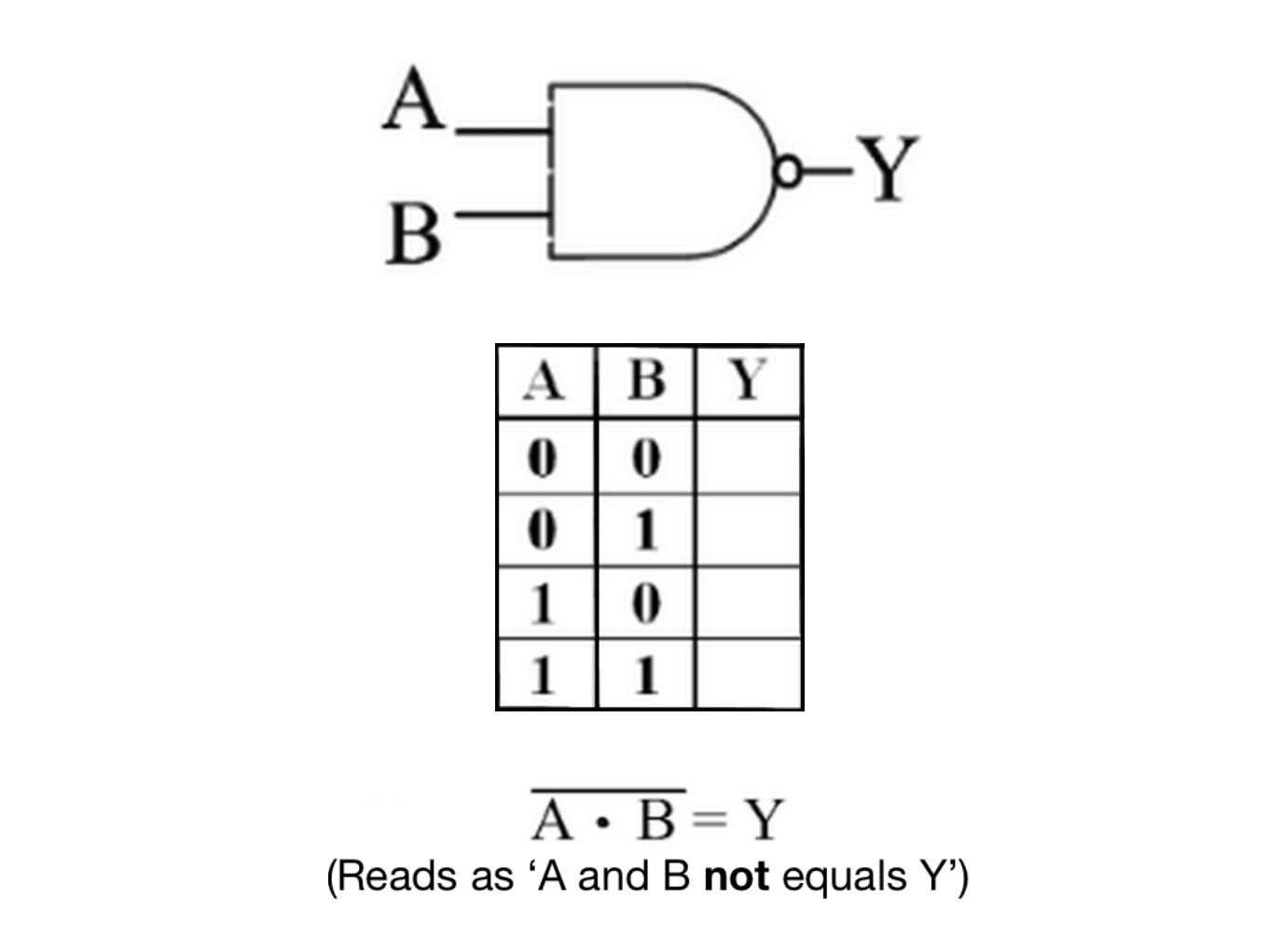
The ‘NAND’ GateThis logic gate operates as an AND gate that is followed by a NOT gate. The output is 0 (Low) only when both inputs are also high. Otherwise the value for the output is 1 (High). Below is a table showing the logical combinations for the NAND gate:
Input 1 (A) Input 2 (B) Output (Y)
0 0 10 1 11 0 11 1 0
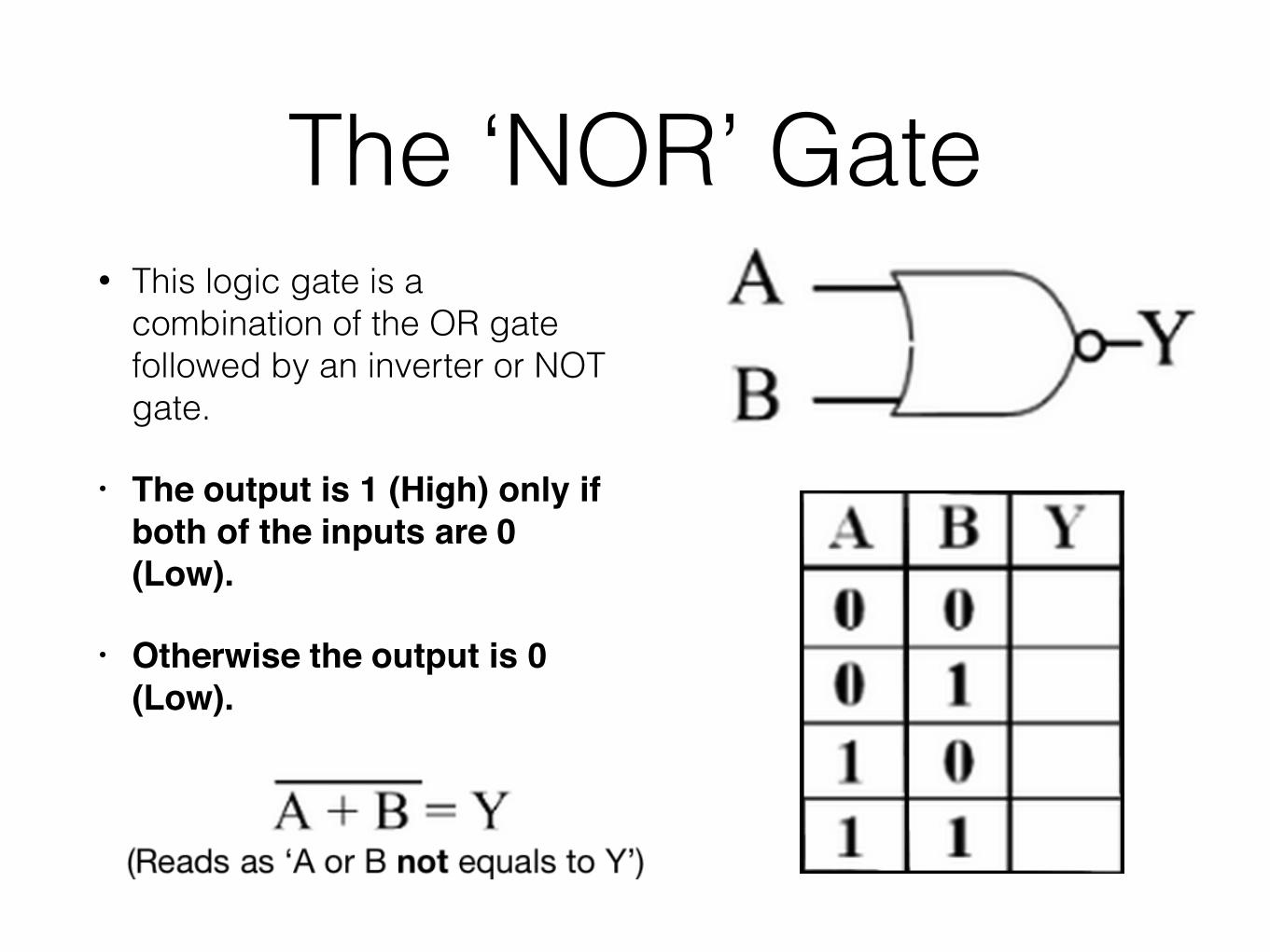
The ‘NOR’ Gate• This logic gate is a
combination of the OR gate followed by an inverter or NOT gate.
• The output is 1 (High) only if both of the inputs are 0 (Low).
• Otherwise the output is 0 (Low).
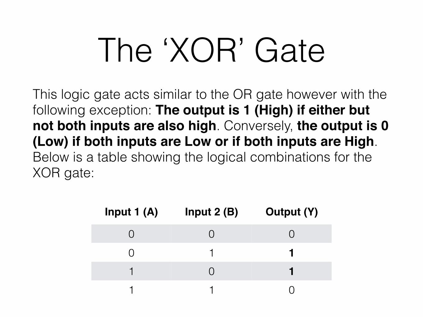
The ‘XOR’ GateThis logic gate acts similar to the OR gate however with the following exception: The output is 1 (High) if either but not both inputs are also high. Conversely, the output is 0 (Low) if both inputs are Low or if both inputs are High. Below is a table showing the logical combinations for the XOR gate:
Input 1 (A) Input 2 (B) Output (Y)
0 0 00 1 11 0 11 1 0

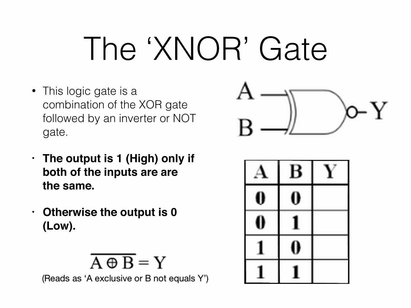
The ‘XNOR’ Gate• This logic gate is a
combination of the XOR gate followed by an inverter or NOT gate.
• The output is 1 (High) only if both of the inputs are are the same.
• Otherwise the output is 0 (Low).
Closing RemarkIt is by using combinations of logic gates, that complex operations can be performed.
In theory, there is no limit to the number of gates than can be arranged together in a single device, but in practice, there is always a limit to how many components that can be packed into a given physical space.
Arrays of logic gates are found in many digital integrated circuits. As technology advances, the required physical volume for each individual logic gate decrease and overall digital devices become smaller and capable of even more complicated operations at an increased speed.