cse 291 winter 2009 the fpga ecosystem - ucsd mesl...
TRANSCRIPT
CSE 291 Winter 2009
The FPGA Ecosystem
Rajesh GuptaUniversity of California, San Diego

2
Moore’s Law
40048008
80808085
8086286
386486 Pentium ® proc
P6
1
10
100
1970 1980 1990 2000 2010Year
Die
siz
e (m
m)
~7% growth per year~2X growth in 10 years
Die size grows by 14% to satisfy Moore’s LawDie size grows by 14% to satisfy Moore’s Law
Courtesy, Intel
40048008
80808085 8086
286386
486Pentium® proc
P6
0.001
0.01
0.1
1
10
100
1000
1970 1980 1990 2000 2010Year
Tran
sist
ors
(MT)
2X growth in 1.96 years!
Transistors on lead microprocessors double every 2 yearsTransistors on lead microprocessors double every 2 years
Courtesy, Intel
Lead microprocessors frequency doubles every 2 yearsLead microprocessors frequency doubles every 2 years
P6Pentium ® proc
48638628680868085
8080800840040.1
1
10
100
1000
10000
1970 1980 1990 2000 2010
Freq
uenc
y (M
hz)
2X every 2 years
Courtesy, Intel
P6Pentium ® proc
486386
2868086
80858080
80084004
0.1
1
10
100
1971 1974 1978 1985 1992 2000Year
Pow
er (W
atts
)

3
The ITRS: Tao of Scalinghttp://public.itrs.net
Source: Ken Yang, UCLA
4 20074 0.065 micron
4 6.7 GHz on chip clock4 9 wiring levels4 600-3000 pins4 Vdd=0.7-1.1V
4 3.5W / 104W / 190W4 DRAM:
4.29 Gb/chip, 183 mm^2, 2.35 Gb/cm^24 MPU
386 Mtrans/chip, 140 mm^2, 276.1 Mtrans/cm^2

4
Design Abstraction Levels
SYSTEM
GATE
CIRCUIT
VoutVin
CIRCUIT
VoutVin
MODULE
+
DEVICE
n+S D
n+
G
Adapted from Irwin & Nayaranan’s Slides from PSU. Copyright 2002 J. Rabaey et al."

5
Design Process
• Conceptualization: function & structure– HLM, behavioral modeling
• Architecture: structure and organization– microarchitectural implementation
• Logical implementation: gates, modules– logic synthesis, logic verification, static timing analysis
• Circuit implementation: transistors– circuit simulations
• Physical design, verification– floorplanning, placement, routing, dynamic timing analysis

6
Speed Power Cost
High LowVolume
Many Implementation Choices
• Microprocessors• Domain-specific processors
– DSP– Network processors– Microcontrollers
• ASIPs• Reconfigurable SoC• FPGA• Gate-array• ASIC

7
E.g. Degree of Customization of Processor Architecture
• The architecture of the computation engine used to implement desired functionality
• Processor does not have to be programmable– “Processor” not equal to general-purpose processor
Application-specific
Registers
CustomALU
DatapathController
Program memory
Assembly code for:
total = 0for i =1 to …
Control logic and State register
Datamemory
IR PC
Single-purpose (“hardware”)
DatapathController
Controllogic
State register
Datamemory
index
total
+
IR PC
Registerfile
GeneralALU
DatapathController
Program memory
Assembly code for:
total = 0for i =1 to …
Control logic and
State register
Datamemory
General-purpose (“software”)
[Adapted from Embedded Systems Design: A Unified Hardware/Software Introduction. Copyright 2000 Vahid & Givargis]
total = 0for i = 1 to N loop
total += M[i]end loop

8
General-purpose Microprocessors• Programmable device used in a variety of
applications– Also known as “microprocessor”
• Features– Program memory– General datapath with large register file and
general ALU• User benefits
– Low time-to-market and NRE costs– High flexibility
• “Pentium” the most well-known, but there are hundreds of others
IR PC
Registerfile
GeneralALU
DatapathController
Program memory
Assembly code for:
total = 0for i =1 to …
Control logic and
State register
Datamemory
[Adapted from Embedded Systems Design: A Unified Hardware/Software Introduction. Copyright 2000 Vahid & Givargis]

9
Application-specific Instruction Processors, ASIP
• Programmable processor optimized for a particular class of applications having common characteristics– Compromise between general-purpose and
single-purpose processors• Features
– Program memory– Optimized datapath– Special functional units
• Benefits– Some flexibility, good performance, size and
power
IR PC
Registers
CustomALU
DatapathController
Program memory
Assembly code for:
total = 0for i =1 to …
Control logic and
State register
Datamemory
[Adapted from Embedded Systems Design: A Unified Hardware/Software Introduction. Copyright 2000 Vahid & Givargis]

10
Single-purpose ‘Processors,’ or ASIC
• Digital circuit designed to execute exactly one program– a.k.a. coprocessor, accelerator or peripheral
• Features– Contains only the components needed to execute a
single program– No program memory
• Benefits– Fast– Low power– Small size
DatapathController
Control logic
State register
Datamemory
index
total
+
[Adapted from Embedded Systems Design: A Unified Hardware/Software Introduction. Copyright 2000 Vahid & Givargis]

11
E.g. ASIC
• A direct sequence spread spectrum (DSSS) radio receiver ASIC (UCLA)
ASIC FeaturesArea: 4.6 mm x 5.1 mmSpeed: 20 MHz @ 10 McpsTechnology: HP 0.5 μmPower: 16 mW - 120 mW (mode dependent)
@ 20 MHz, 3.3 VAvg. Acquisition Time: 10 μs to 300 μs

12
The Implementation Choice is Important

13
The Co-design Ladder
• In the past:– Hardware and software
design technologies were very different
– Recent maturation of synthesis enables a unified view of hardware and software
• Hardware/software “codesign”
Implementation
Assembly instructions
Machine instructions
Register transfers
Compilers(1960's,1970's)
Assemblers, linkers(1950's, 1960's)
Behavioral synthesis(1990's)
RT synthesis(1980's, 1990's)
Logic synthesis(1970's, 1980's)
Microprocessor plus program bits: “software”
VLSI, ASIC, or PLD implementation: “hardware”
Logic gates
Logic equations / FSM's
Sequential program code (e.g., C, VHDL)
The choice of hardware versus software for a particular function is simply a tradeoff among various design metrics, like performance, power, size, NRE cost, and especially flexibility; there is no
fundamental difference between what hardware or software can implement.[Adapted from Embedded Systems Design: A Unified Hardware/Software Introduction. Copyright 2000 Vahid & Givargis]

14
Map from Behavior to Architecture
[Vincentelli]

15
Four Phases in Creating a Chip

16
Implementation Choices
Custom
Standard CellsCompiled Cells Macro Cells
Cell-based
Pre-diffused(Gate Arrays)
Pre-wired(FPGA's)
Array-based
Semicustom
Digital Circuit Implementation Approaches
Adapted from Digital Integrated Circuits (2nd Edition). Copyright 2002 J. Rabaey et al."

17
Transition to Automation and Regular Structures
Intel 4004 (Intel 4004 (‘‘71)71)Intel 8080Intel 8080 Intel 8085Intel 8085
Intel 8286Intel 8286 Intel 8486Intel 8486Courtesy IntelAdapted from Digital Integrated Circuits (2nd Edition). Copyright 2002 J. Rabaey et al."

18
Cell-based Design (or standard cells)
Routing channel requirements arereduced by presenceof more interconnectlayers
Functionalmodule(RAM,multiplier, …)
Routingchannel
Logic cellFeedthrough cellR
ows
of c
ells
Adapted from Digital Integrated Circuits (2nd Edition). Copyright 2002 J. Rabaey et al."

19
Standard Cell - Example
3-input NAND cell(from ST Microelectronics):C = Load capacitanceT = input rise/fall time
Adapted from Digital Integrated Circuits (2nd Edition). Copyright 2002 J. Rabaey et al."
20
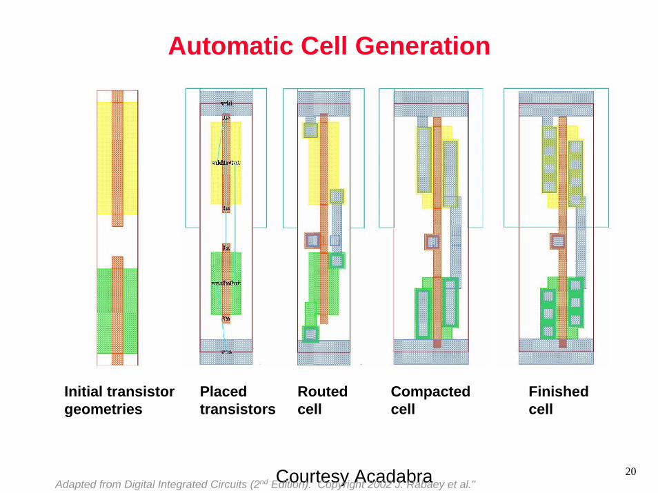
Automatic Cell Generation
Courtesy Acadabra
Initial transistorgeometries
Placedtransistors
Routedcell
Compactedcell
Finishedcell
Adapted from Digital Integrated Circuits (2nd Edition). Copyright 2002 J. Rabaey et al."

21
MacroModules
256×32 (or 8192 bit) SRAMGenerated by hard-macro module generator
Adapted from Digital Integrated Circuits (2nd Edition). Copyright 2002 J. Rabaey et al."

22
“Soft” MacroModules
Synopsys DesignCompilerAdapted from Digital Integrated Circuits (2nd Edition). Copyright 2002 J. Rabaey et al."

23
“Intellectual Property”
A Protocol Processor for Wireless
Adapted from Digital Integrated Circuits (2nd Edition). Copyright 2002 J. Rabaey et al."

24
Semicustom Design Flow
HDLHDL
Logic SynthesisLogic Synthesis
FloorplanningFloorplanning
PlacementPlacement
RoutingRouting
Tape-out
Circuit ExtractionCircuit Extraction
Pre-Layout Simulation
Pre-Layout Simulation
Post-Layout Simulation
Post-Layout Simulation
StructuralStructural
PhysicalPhysical
BehavioralBehavioralDesign Capture
Des
ign
Itera
tion
Des
ign
Itera
tion
Adapted from Digital Integrated Circuits (2nd Edition). Copyright 2002 J. Rabaey et al."

25
Pre-diffused(Gate Arrays)
Pre-wired(FPGA's)
Array-based
Late-Binding Implementation
Custom
Standard CellsCompiled Cells Macro Cells
Cell-based
Pre-diffused(Gate Arrays)
Pre-wired(FPGA's)
Array-based
Semicustom
Digital Circuit Implementation Approaches
Adapted from Digital Integrated Circuits (2nd Edition). Copyright 2002 J. Rabaey et al."

26
Gate Array — Sea-of-gates
rows of
cells
routing channel
uncommitted
VD D
GND
polysilicon
metal
possiblecontact
In1 In2 In3 In4
Out
UncommitedCell
CommittedCell(4-input NOR)
Adapted from Digital Integrated Circuits (2nd Edition). Copyright 2002 J. Rabaey et al."

27
Sea-of-gate Primitive Cells
NMOS
PMOS
Oxide-isolation
PMOS
NMOS
NMOS
Using oxide-isolation Using gate-isolation
Adapted from Digital Integrated Circuits (2nd Edition). Copyright 2002 J. Rabaey et al."

28
Prewired Arrays
Classification of prewired arrays (or field-programmable devices):
• Based on Programming Technique– Fuse-based (program-once)– Non-volatile EPROM based– RAM based
• Programmable Logic Style– Array-Based– Look-up Table
• Programmable Interconnect Style– Channel-routing– Mesh networks
Adapted from Digital Integrated Circuits (2nd Edition). Copyright 2002 J. Rabaey et al."

29
Antifuse
• Normally high resistance (> 100 MΩ)– on application of
appropriate voltage, the antifuse is changed permanently to a low resistance structure (200-500Ω)

30
Array-Based Programmable Logic
PLA PROM PAL
I5 I4
O0
I3 I2 I1 I0
O1O2O3
Programmable AND array
ProgrammableOR array I5 I4
O0
I3 I2 I1 I0
O1O2O3
Programmable AND array
Fixed OR array
Indicates programmable connection
Indicates fixed connection
O0
I3 I2 I1 I0
O1O2O3
Fixed AND array
ProgrammableOR array
Adapted from Digital Integrated Circuits (2nd Edition). Copyright 2002 J. Rabaey et al."

31
Programming a PROM
f0
1 X 2 X 1 X 0
f1NANA: programmed node
Adapted from Digital Integrated Circuits (2nd Edition). Copyright 2002 J. Rabaey et al."

32
2-input muxas programmable logic block
FA 0
B
S
1
ConfigurationA B S F=0 0 0 00 X 1 X0 Y 1 Y0 Y X XYX 0 YY 0 XY 1 X X 1 Y1 0 X1 0 Y1 1 1 1
XYXY
XY
Adapted from Digital Integrated Circuits (2nd Edition). Copyright 2002 J. Rabaey et al."
33
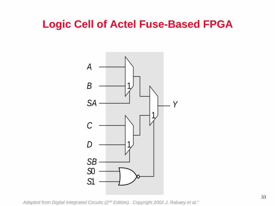
Logic Cell of Actel Fuse-Based FPGA
A
B
SA Y
1
C
D
SB
1
S0S1
1
Adapted from Digital Integrated Circuits (2nd Edition). Copyright 2002 J. Rabaey et al."

34
Look-up Table Based Logic Cell
Out
ln1 ln2
Mem
ory In Out
00 00
01 1
10 1
11 0
Adapted from Digital Integrated Circuits (2nd Edition). Copyright 2002 J. Rabaey et al."
35
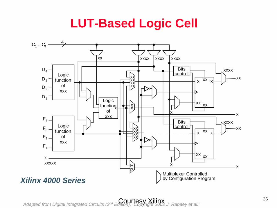
LUT-Based Logic Cell
Courtesy Xilinx
D4
C1....C4
xxxxxx
D3
D2
D1
F4
F3
F2
F1
Logicfunction
ofxxx
Logicfunction
ofxxx
Logicfunction
ofxxx
xx
xx
4
xxxxxx
xxxxxxxx
xxx
xxxx xxxx xxxx
HP
Bitscontrol
Bitscontrol
Multiplexer Controlledby Configuration Program
x
xx
x
xx
xxx xx
xxxx
x
xxxxxx
xx
x
xx
xxx
xx
Xilinx 4000 Series
Adapted from Digital Integrated Circuits (2nd Edition). Copyright 2002 J. Rabaey et al."

36
Array-Based Programmable Wiring
Input/output pinProgrammed interconnection
InterconnectPoint
Horizontaltracks
Vertical tracks
Cell
M
Adapted from Digital Integrated Circuits (2nd Edition). Copyright 2002 J. Rabaey et al."

37
Mesh-based Interconnect NetworkSwitch Box
Connect Box
InterconnectPoint
Courtesy Dehon and WawrzyniekAdapted from Digital Integrated Circuits (2nd Edition). Copyright 2002 J. Rabaey et al."

38
Transistor Implementation of Mesh
Courtesy Dehon and WawrzyniekAdapted from Digital Integrated Circuits (2nd Edition). Copyright 2002 J. Rabaey et al."

39
Hierarchical Mesh Network
Use overlayed meshto support longer connections
Reduced fanout and reduced resistance
Courtesy Dehon and WawrzyniekAdapted from Digital Integrated Circuits (2nd Edition). Copyright 2002 J. Rabaey et al."

40
EPLD Block Diagram
MacrocellPrimary inputs
Courtesy AlteraAdapted from Digital Integrated Circuits (2nd Edition). Copyright 2002 J. Rabaey et al."
41
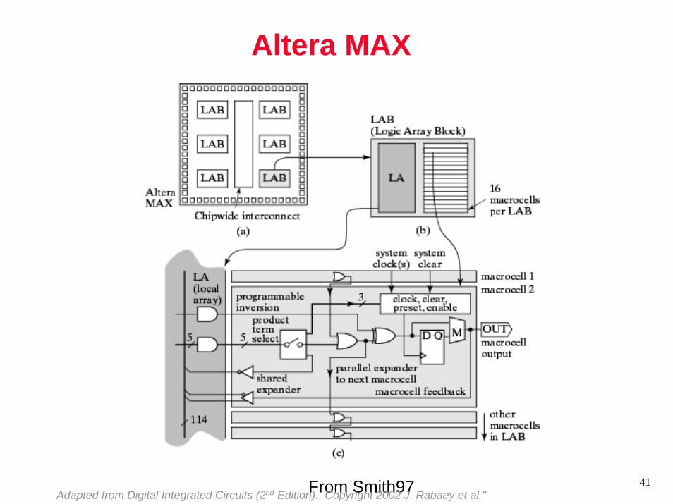
Altera MAX
From Smith97Adapted from Digital Integrated Circuits (2nd Edition). Copyright 2002 J. Rabaey et al."

42
Altera MAX Interconnect Architecture
LAB2
PIA
LAB1
LAB6
tPIA
tPIA
row channelcolumn channel
LAB
Courtesy AlteraAdapted from Digital Integrated Circuits (2nd Edition). Copyright 2002 J. Rabaey et al."
Array-based(MAX 3000-7000)
Mesh-based(MAX 9000)

43
Field-Programmable Gate ArraysFuse-based
I/O Buffers
Program/Test/Diagnostics
I/O Buffers
I/O B
uffe
rs
I/O B
uffe
rs
Vertical routes
Rows of logic modulesRouting channels
Standard-cell likefloorplan
Adapted from Digital Integrated Circuits (2nd Edition). Copyright 2002 J. Rabaey et al."

44
Xilinx 4000 Interconnect Architecture
2
12
8
4
3
2
3
CLB
8 4 8 4
Quad
Single
Double
Long
DirectConnect
DirectConnect
Quad Long GlobalClock
Long Double Single GlobalClock
CarryChain
Long12 4 4
Courtesy XilinxAdapted from Digital Integrated Circuits (2nd Edition). Copyright 2002 J. Rabaey et al."

45
RAM-based FPGA
Xilinx XC4000ex
Courtesy XilinxAdapted from Digital Integrated Circuits (2nd Edition). Copyright 2002 J. Rabaey et al."

46
Heterogeneous Programmable Platforms
Xilinx Vertex-II Pro
Courtesy Xilinx
High-speed I/O
Embedded PowerPcEmbedded memories
Hardwired multipliers
FPGA Fabric
Adapted from Digital Integrated Circuits (2nd Edition). Copyright 2002 J. Rabaey et al."

SOC as a heterogeneous computing substrate
ASIC
DSPCode
System Bus
Proc.Code
CODEC
Analoginterface
ProgrammableProcessor CoreMemory Interface
Host/Bus InterfaceProgrammable
DSP CoreMemory Interface
Host/Bus Interface
User interface
Multi-ported memory
Real time Operating System
Code
MicroprocessorCore
ASIC
Controller process
BUSCNTL
SERIAL I/O
ASICASIC
DSPCodeDSPCode
System Bus
Proc.CodeProc.Code
CODEC
Analoginterface
ProgrammableProcessor CoreMemory Interface
Host/Bus InterfaceProgrammableProcessor CoreMemory Interface
Host/Bus InterfaceProgrammable
DSP CoreMemory Interface
Host/Bus InterfaceProgrammable
DSP CoreMemory Interface
Host/Bus Interface
User interface
User interface
Multi-ported memoryMulti-ported memory
Real time Operating System
Code
MicroprocessorCore
Real time Operating System
Real time Operating System
CodeCode
MicroprocessorCore
ASICASIC
Controller process
BUSCNTL
SERIAL I/O

Experimental Side of Putting Things Together

Design
Goal of design is to take an ‘idea’ and build something that performance a certain functionSuch ‘idea’ to ‘implementation’ never happen directly
We go through ‘models’ that allow us to reason about propertiesMay also be used by implementers to explore alternatives for cost, performance
MODELS are key to formalization of the designAnd its process.
Model of Computation
A ‘model’ is an abstraction of a ‘description’(Sometimes, a model is also used as a replica of a ‘description’)
This abstraction is defined using some ‘terms’If the terms are graphical graphical modelIf the terms are mathematical formal modelGenerally, terms and their relationships are devised to allow syntactical support for expressing important conceptsIf done right, a MOC
supports important concepts of an application domain through use of right terms is clear and unambiguous to allow anyone to replicate/simulate intended behavioris compositional: compositions can be validated with less effortthan ab initio description

Compositional View of SOCs:Model of Computation
A system consists of componentsImportant questions to ask when dealing with components
What is a component? (Component ontology)States? Processes? Threads? Differential equations? Constraints? Objects? …
What knowledge do components share? (Epistemology)Time? Name spaces? Signals? State?
How do components communicate? (Protocols)Events? Rendezvous? Message Passing? CT Signals? Streams? Method Calls? …
What do components communicate? (Lexicon)Objects? Transfer of control? Data structures? Strings?...
A MOC makes it easier to reason through these questionsStart with a model of a machine, define its behavior (as

Characteristics of Common MOCs
Finite State MachinesState is summary of past, Finite number of statesNo concurrency, no explicit time specification
Data-FlowPartial order of actions/eventsConcurrency, determinate, support streams (data, computation)
Discrete-event modelsGlobal notion of time, causality

Finite State Machines (FSMs)
Functional decomposition into states of operationUseful for control functions, protocols
Properties of FSMsGood for specifying sequential control.Not Turing complete.
More amenable to formal analysis.Typical domains of application
Control-intensive tasks.Protocols (Telecom, cache-coherency, bus, ...)
Many variants of the formulationDiffer in communication, determinism, ...

ALARM
OFF5_SECONDS_UP => ALARM_ON
WAIT
KEY_OFF or BELT_ON
KEY_ON => START_TIMER
10_SECONDS_UP or BELT_ON or KEY_OFF => ALARM_OFF
Informal SpecificationIf the driver
turns on the key, and does not fasten the seat belt within 5 seconds
then sound the alarm for 5 seconds, or until the driver fastens the seat beltor until the driver turns off the key
No explicit condition => implicit self-loop in the current state
FSM Example: Seat Belt Alarm Control

FSM = (Inputs, Outputs, States, InitialState, NextState, Outs)
Inputs = {KEY_ON, KEY_OFF, BELT_ON, BELT_OFF, 5_SECONDS_UP, 10_SECONDS_UP}Outputs = {START_TIMER, ALARM_ON, ALARM_OFF}States = {OFF, WAIT, ALARM}
InitialState = OFFNextState: CurrentState, Inputs -> NextState
e.g., NextState(WAIT, {KEY_OFF}) = OFFAll inputs other than KEY_OFF are implicitly absent
Outs (function): CurrentState, Inputs -> Outputs
e g Outs(OFF {KEY ON}) =
ALARM
OFF5_SECONDS_UP => ALARM_ON
WAIT
KEY_OFF or BELT_ON
KEY_ON => START_TIMER
10_SECONDS_UP or BELT_ON or KEY_OFF => ALARM_OFF
Finite State Machine: Example + Definition
NextState: 2Inputs x S -> SSet of all subsets of I
Outs: 2Inputs x S -> 2Outputs

A finite state machine is said to be non-deterministic when The NextState and Output functions may be RELATIONs (instead of functions).NextState(WAIT, {KEY_OFF, END_TIMER_5})={{OFF},{ALARM}}
Non-determinism can be user to modelunspecified behavior
incomplete specificationunknown behavior
e.g., the environment modelDriver can be modeled as single state FSM with outputs {KEY_ON, KEY_OFF, BELT_ON}
abstraction(the abstraction may result in insufficient detail to identify
i l di ti i h bl it ti )
Non-deterministic Finite State Machines

Concurrency and FSM
Significant model change: treat it as a ‘collection’Fundamental assumption: all FSMs change states together (synchronicity)
System state is a cartesian productState space can be reduced by constrained compositions
E.g., sequential composition: output of one machine is input of another
A cleaner way to extend FSM model?Hierarchy

Discrete Event Models
Action, EventsNotion of global time
Though it is not fundamental: time progress can be captured by ‘special’ events
Events can happen anytime asynchronouslyA system consists of components with input events and output events
Also, referred to as ‘primary events’.
Component is evaluated in response to input events Evaluation leads to events at the output
A discrete event simulator is a program that specifies how components are evaluated
Components at a time (‘clock-driven’)Event at a time (‘event-driven’)

Reactive Systems“React” to events
e.g., in the external environment, other subsystemsSuited for modeling “non-terminating” interactions
e.g., operating systems, interrupt handlers, process control systems.Often subject to external timing constraints
“real-time”Synchronous Reactive Systems
Synchrony associates ‘clock’ to a modelAll ‘synchronous events’ happen simultaneously
Clock is a ‘simplifcation’ or abstraction of time in modelsBetween clocks, any amount of time can pass
Reactive (Real-time) Systems

60
Four useful MOCs
• Discrete Event (DE)– Timed models, suitable for modeling digital hardware– But can be very general (define what is an event and what happens to it)
• Finite State Machines– Variants and extensions: StateCharts, StarCharts
• Synchronous Reactive Models– Synchrony assumption useful for safety critical embedded systems
(instantaneous reactions)• (Convert timing relations to causal ordering)
– A program is logically correct if it is deterministic and reactive– Verifying that a program is causal is a challenge
• Want one and only solution for each configuration of inputs – Assume “constructive causality” to make it work
• Still a lot better than multi-level time (delta) models• Dataflow Process Networks
– Signal processing applications

61
Compositional Correctness
• Build “Complete” System Models– That include the application and system software– Adapt, control and debug applications– Explore the full potential of SOC architectural platforms
• e.g., by exploring applications, networking and communication subsystems together
• Composition challenges– Language support for multiple MOCs not enough– Model composability may not be guaranteed
• E.g., composition of synchronous models may not be closed• Like connecting two FSMs can lead to combinational cycles
– solutions like: delta steps (VHDL), acyclic composition (Lustre), reactions as fixed points (Esterel

62
Going Across MOC: Ptolemy Approach
• Encapsulate each description in a MOC in a “domain”• Inter-domain simulations achieved through domain
encapsulation– Define semantics of every such encapsulation carefully,
conservatively (and yet with some efficiency)• The “event horizon”
– Couple timed, untimed domains

63
Network Architecture Modeling: NS2
• Developed under the Virtual Internet Testbed (VINT) project (UCB, LBL, USC/ISI, Xerox PARC)
• Captures network nodes, topology and provides efficient event driven simulations with a number of “schedulers”
• Interpreted interface for– network configuration, simulation setup– using existing simulation kernel objects such as predefined
network links• Simulation model in C++ for
– packet processing– changing models of existing simulation kernel classes, e.g.,
using a special queuing discipline.

64
NS2 Simulations

65
A 4-node system with 2 “agents”, a traffic generator
n0UDP
n1TCP
n2 n3Sink
ftp
set ns [new Simulator]set f [open out.tr w]$ns trace-all $fset n0 {$ns node}set n1 {$ns node}set n2 {$ns node}set n3 {$ns node}$ns duplex-link $no $n2 5Mb 2ms DropTail$ns duplex-link $n1 $n2 5Mb 2ms DropTail$ns duplex-link $n2 $n3 1.5Mb 10ms DropTailset udp0 [newagent/UDP]$ns attach-agent $n0 $udp0set cbr0 [newapplication/Traffic/CBR]$cbr0 attach-agent $udp0..$ns at 3.0 “finish”proc finish () {
…}$ns run
• “Agents” are network endpoints where network-layer packets are constructed or consumed.

66
NS2 Usage: LAN nodes
• LAN and wireless links are inherently different from PTP links due to sharing and contention properties of LANs
– a network consisting of PTP links alone can not capture LAN contention properties
– a special node is provided to specify LANs• LanNode captures functionality of three lowest layers in the
protocol stack, namely: link, MAC and physical layers.– Specifies objects to be created for LL, INTF, MAC and Physical
channels.– Example:$ns make-lan <nodelist> <bw> <delay> <LL> <ifq> <MAC> <channel> <phy>$ns make-lan “$n1 $n2” $bw $delay LL queue/DropTail Mac/CSMA/CD.
– Creates a LAN with basic link-layer, drop-tail queue and CSMA/CD medium access control.
n1 n2
n3
n1 n2
n3
LAN
The LAN node collects all the objects shared on the
LAN.

67
node1
Q
LL
MAC
node2
Q
LL
MAC
node3
Q
LL
MAC
Channel MAC classifier
LL
MAC
Phy
Channel object simulates the shared medium and supports the medium access mechanisms
of the MAC objects on the sending side.
On the receiving side, MAC classifier is responsible for delivering and optionally replicating packets to the receiving MAC
objects.
Network Stack simulation for LAN nodes in ns
Objects used in LAN nodes. Each of the underlying classes can be specialized for a given simulation.

68
Putting things together…
Source: Virtio Corp.
ASIC HardwareNetwork
Processor(s) and MemoriesSystem Software: OS, Middleware, Application Software

69
Time Granularity in ModelsA. "Specification model" "Untimed functioal models"
B. "Component-assembly model" "Architecture model" "Timed functonal model"
C. "Bus-arbitration model" "Transaction model"
D. "Bus-functional model" "Communicatin model" "Behavior level model"
E. "Cycle-accurate computationmodel"
F. "Implementation model" "Register transfer model"
Computation
Communication
A B
C
D F
Un-timed
Approximate-timed
Cycle-timed
Un-timed
Approximate-timed E
Cycle-timed
• Models B, C, D and E could be classified as TLMs.
Source: Daniel Gajski, UC Irvine.

70
Hardware-software co-simulation
• Verification of the functionality of a system consisting of both hardware and software (as early as possible in the design cycle).
ProcessorModel
CustomHardware
ModelCommunication
• BFM• ISA• CAM• TAM
• Functional• Behavioral• RTL• Gate• Transistor
• Tightly coupled• Loosely coupled• One process• Multi-process
71
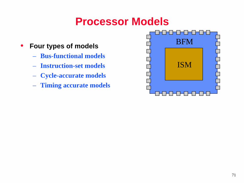
Processor Models
• Four types of models– Bus-functional models– Instruction-set models– Cycle-accurate models– Timing accurate models
BFM
ISM

72
Bus-functional Models
• Can only execute bus transactions• Can be used to check how peripherals interact with the processor bus• Available in different degrees of timing accuracy
– Cycle-accurate– Phase-accurate– Full timing (nanosecond) accurate
• Very popular in hardware design
BFM
CLK
ADDRESS
CE
DATA
R/W
Rea
d fr
om 0
xff0
0

73
Instruction-set (ISA) Models
• Basic ISA Model– Model only the effect of
instruction execution on registers and memory
– Not processor pipeline– Fast, used in embedded
software models• Cylcle-accurate ISA
– Model the processor pipeline and instruction execution in a cycle-accurate manner
– Provides accurate cycle counts for instruction execution
– 1.2-5X slower
Fetch ExecuteDecode
Register File
Memorymov r0, r1add r0, r2, r3st r0, (r5)

74
Processor Models• ISA Processor Model
– ISA Model + Cycle-accurate BFM– Cycle accurate bus transactions but not cycle
accurate instruction execution– Fastest useful processor model
• Cycle-accurate Processor Model– Cycle-accurate ISA + Cycle-accurate BFM– Cycle accurate instruction execution and bus
transactions– Slower than ISA processor model but still popular.
BFM
ISM

75
Timing-accurate Models
• Correctly models the processor behavior at the nanosecond accurate level
• Is usually generated from a gate-level netlist of the processor
• Slow (could be 3 to 5 orders of magnitude slower than cycle-accurate processor models)
• Seldom used

76
Typical Usage Models
• System architects looking at hardware/software tradeoffs• ASIC developers wanting a fast and easy way to test out the
hardware running actual code• Software developers testing H/W drivers and RTOS on
hardware (HDL) models• Software developers testing application code with an RTOS
on the “real” hardware (i.e. evaluation board)• Distributed application developers
– SensorSIM, TOSSIM