cscd 433/533 wireless networks and...
TRANSCRIPT

1
CSCD 433/533Wireless Networks and Security
Lecture 8Physical Layer, and 802.11 b,g,a,n,ac
Differences
Spring 2016

2
Topics
Differences between 802.11 b,g,a and n− Frequency ranges− Speed
Spread Spectrum Techniques in General DSSS Spread Spectrum, 802.11b OFDM and 802.11n
3
Introduction
Today, discuss physical layer of 802.11 standard
Many techniques have helped to increase throughput as versions evolved over time
We will start with slowest and end with fastest Note, we will not cover 802.11ac
4
FCC Regulation
In 1995, Federal Communications Commission allocated several bands of wireless spectrum for use without license
FCC stipulated that use of spread spectrum technology would be required
Recall, that in 1990, IEEE began exploring a standard for Wireless LAN's
July 1997 initial attempt, in 1999 the 802.11b standard was ratified, first popular version

Spread Spectrum Defined
Spread spectrum communication technique that spreads narrowband communication signal over wider range of frequencies for transmission then de-spreads it into original data bandwidth at receiver
Spread spectrum is characterized by Wide bandwidth and Low power
Jamming and Interference have less effect on Spread spectrum because
Resembles noise Hard to detect Hard to intercept

5-6
Spread Spectrum Transmission
• Spread Spectrum Transmission– You are required by law to use spread spectrum
transmission in unlicensed bands– Spread spectrum transmission reduces propagation
problems• Especially multipath interference
– Spread spectrum transmission is NOT used for security in WLANs
• Although military does use spread spectrum transmission to make signals hard to detect
• This requires a different spread spectrum technology

7
Frequency BandISM: Industry, Science, Medicine
unlicensed frequency spectrum: 900Mhz, 2.4Ghz, 5.7Ghz

8
IEEE 802.11 Frequency Band
and 802.11b/g 802.11a802.11 ac
Wavelength

9
802.11 Physical Channels
The 802.11b standard defines 14 frequency channels in 2.4GHz range
− Only eleven are allowed for unlicensed use by the FCC in the US
− Each channel uses "Direct Sequence Spread Spectrum" (DSSS) to spread data over channel that extends 11MHz on each side of center frequency
− Channels overlap, but there are three out of 11 channels that don't

10
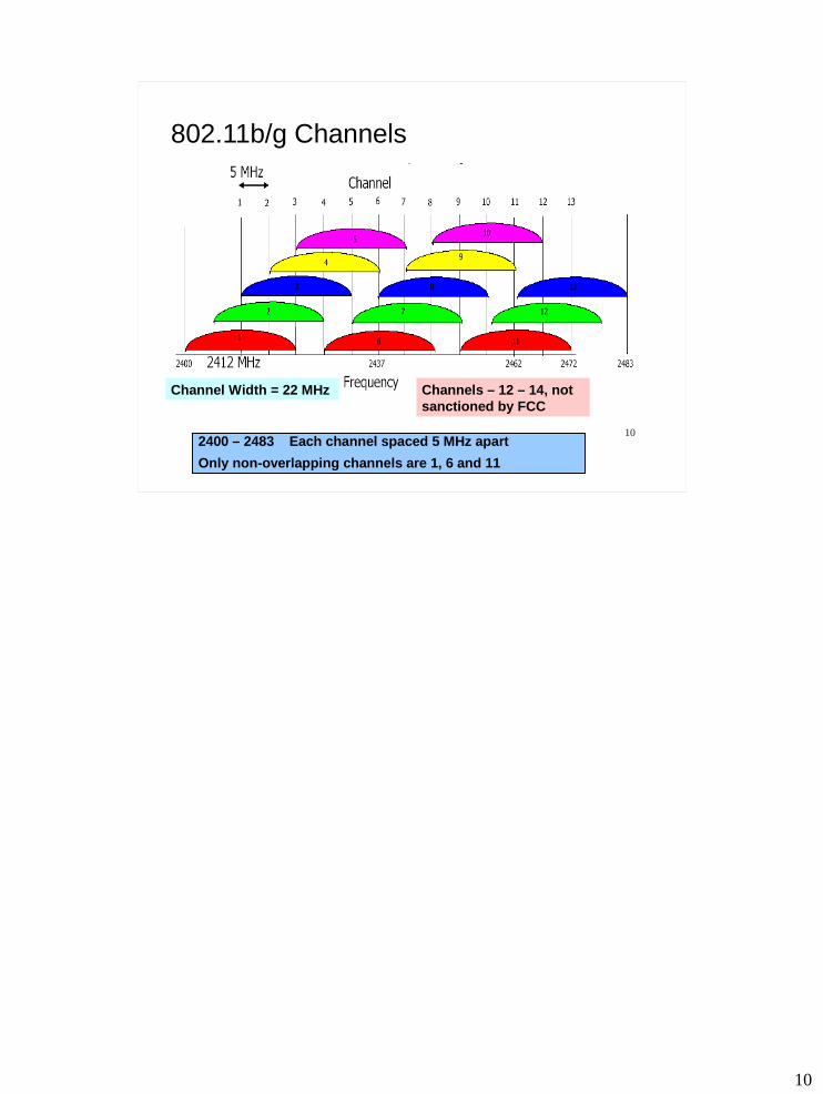
802.11b/g Channels
2400 – 2483 Each channel spaced 5 MHz apart
Only non-overlapping channels are 1, 6 and 11
Channel Width = 22 MHz Channels – 12 – 14, not sanctioned by FCC

Frequency Assignments
Channel 12.412 GHz
Channel 62.437 GHz
Channel 112.462 GHz
25 MHz25 MHz
The Center frequencies of each channel are only 5 Mhz apart but each channel is 22 Mhz wide therefore adjacent channels will overlap.
DSSS systems with overlapping channels in same physical space cause interference between systems.
Co-located DSSS systems should have frequencies which are at least 5 channels apart, e.g., Channels 1 and 6, Channels 2 and 7, etc.
Channels 1, 6 and 11 are the only theoretically non-overlapping channels.

12
Radio Communications
How do you transmit Radio Signals reliably?− Classic approach ….
Confine information carrying signal to a narrow frequency band and pump as much power as possible into signal
Make sure antenna is able to detect signal− Noise occurs as distortion in frequency band− To overcome noise
Ensure power of signal > noise Recall, SNR = Signal to Noise Ratio
But, what if you deliberately include your
own noise into signal?

13
Radio Communications
Given multiple devices compete in ISM bands, how do you reliably transmit data?
− Spread Spectrum is one of the answers− Native radio signals sent with as much power as
allowed over a narrow band of frequency Spread Spectrum
− Used to transform radio signals for data− Uses math functions to diffuse signal over larger
range of frequencies− Makes transmissions look like noise to narrowband
receiver

14
Radio Communications
Spread Spectrum continued− On receiver side, signal is transformed back to
narrow-band and noise is removed− Spread spectrum is a requirement for unlicensed
devices− Minimize interference between unlicensed devices,
FCC imposes limitations on power of transmissions

15
Radio Communications
Trivia Question− Who patented spread spectrum transmission and
when was it patented?

16
Hedy Lamarr
Austrian actress Hedy Lamarr pioneer in field of wireless communications following her emigration to the United States
With co-inventor George Anthiel, developed a "Secret Communications System" to help combat Nazis in World War II
By manipulating radio frequencies at irregular intervals between transmission and reception, invention formed an unbreakable code to prevent classified messages from being intercepted by enemy personnel
Patented in 1941 Her Story http://www.women-inventors.com/Hedy-Lammar.asp

17
Spread Spectrum 802.11 uses three different Spread Spectrum
technologies1. FH – Frequency Hopping (FHSS)
Jumps from one frequency to another in random pattern− Transmits a short burst at each subchannel
2 Mbps FH or FHSS original spread spectrum technology developed in 1997 with 802.11 standard
However, quickly bypassed by more sophisticated spread spectrum technologies
We won’t cover it … can see below
FHSS covered in, http://www.cs.clemson.edu/~westall/851/spread-spectrum.pdf
18
Spread Spectrum Continued
2. DS or DSSS Direct Sequence Took over from FHSS and allowed for faster throughput Used in 802.11b Spreads out signal over a wider path Uses frequency coding functions
3. OFDM – Orthogonal Frequency Division Multiplexing Divides channel into several subchannels and encode a
portion of signal across each subchannel in parallel 802.11a and 802.11g use this technology Allows for even faster throughput than DSSS

19
802.11 Spread Spectrum in General

20
Spread Spectrum Code Techniques
Spread-spectrum is a signal propagation technique
− Employs several methods Decrease potential interference to other
receivers− Generally makes use of noise-like signal structure to
spread normally narrowband signal over relatively wideband (radio) band of frequencies
− Receiver correlates (matches) received signals to retrieve original information signal

21
Spread Spectrum Code Techniques
Three characteristics of Spread Spectrum techniques
1. Signal occupies bandwidth much greater than that is necessary to send the information
2. Bandwidth is spread by means of code independent of data 3. Receiver synchronizes code to recover the data

22
Spread Spectrum Techniques
In a spread-spectrum system, signals spread across wide bandwidth, making them difficult to intercept and demodulate
23
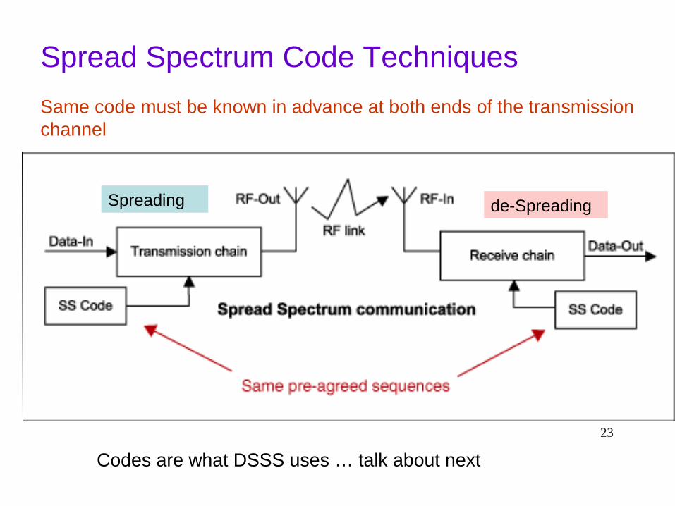
Same code must be known in advance at both ends of the transmission channel
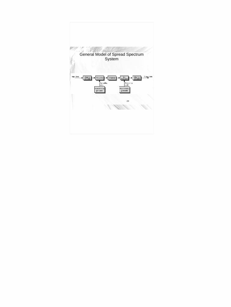
Spread Spectrum Code Techniques
Codes are what DSSS uses … talk about next
Spreading de-Spreading
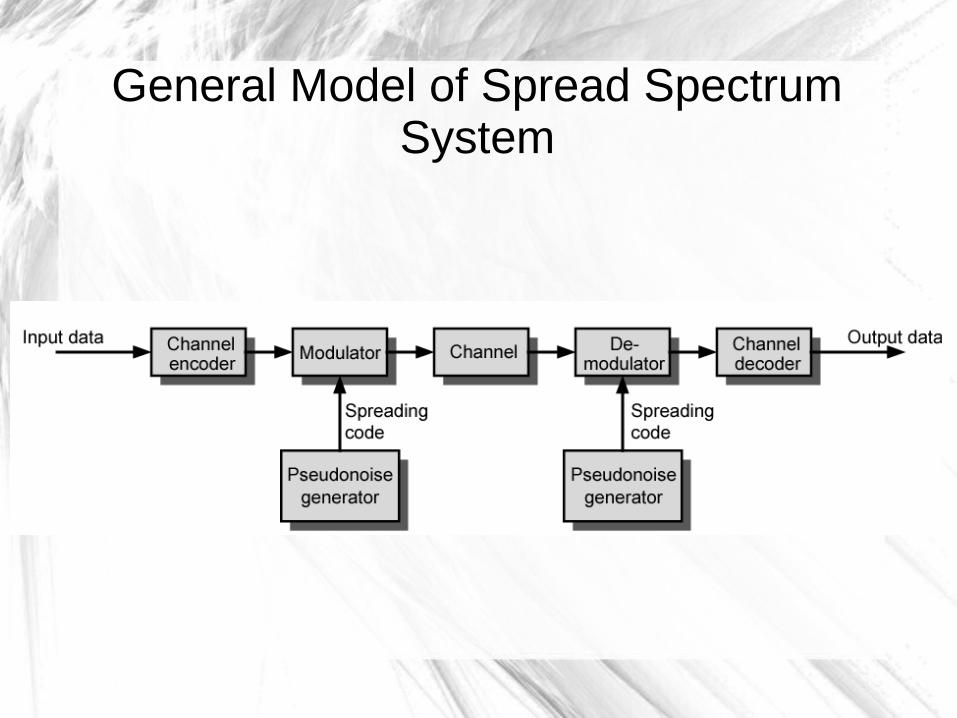
General Model of Spread Spectrum System
25
DSSS and HR/DSSS

26
DSSS
DSSS is a spread spectrum technique− Modulation alters a carrier wave to transmit a data
signal (text, voice, audio, video, etc.) − Phase-modulates a sine wave pseudorandomly
Continuous string of pseudonoise (PN) code symbols called “chips”
Each of which has a shorter duration than an information bit Each information bit is modulated by sequence of much
faster chips

27
DSSS
Why this works ...− To a narrowband receiver, transmitted signal looks like noise− Original signal can be recovered through correlation that
reverses the process− The ratio (in dB) between the spread bandwidth to the
unspread bandwidth is known as processing gain
Example
1 kHz signal is spread to 100 kHz
Process gain would be 100,000/1,000 = 100
In decibels, 10 log10(100) = 20 dB
− Typical SS processing gains run from 10dB to 60dB

28
DSSS
How DSSS works − Apply something called a “chipping” sequence to
the data stream− Chip is a binary digit− But, spread-spectrum developers make distinction
to separate encoding of data from the data itself Talk about data is bits Talk about encoding is chips or chipping sequence

29
DSSS Example
Chipping sequence− Also called Pseudorandom Noise Codes (PNC)− Must run at a higher rate than underlying data− See next slide ...
At left, is a data bit 0 or 1 For each bit, chip sequence is used Chip is an 11 bit code combined with a data bit to
produce an 11 bit code This gets transmitted to receiver

30
DSSS Chipping Sequence Example
Data SpreadingEncoded Data Correlation
1
0
1
0
Modulo 2
add
Spreading Code
10110111000
10110111000
01001000111Modulo 2
Subtract
10110111000
Spreading Code

Figure 6.33 DSSS example
32
DSSS
Encoding DSSS− 802.11 originally adopted an 11-bit Barker word− Each bit encoded using entire Barker word or
chipping sequence− Key attribute of Barker words
Have good autocorrelation properties− High signal recovery possible when signal
distorted by noise Correlation function operates over wide range of
environments and is tolerant of propagation delay
33
DSSS
Encoding DSSS− Why 11 bits?
Regulatory authorities require a 10 dB processing gain in DSSS systems
Using an 11 bit spreading code for each bit let 802.11 meet regulatory requirements
Recall− The ratio (in dB) between the spread baseband and the
original signal is processing gain
Nice Paper on DSSS
http://www.ni.com/white-paper/4450/en/
34
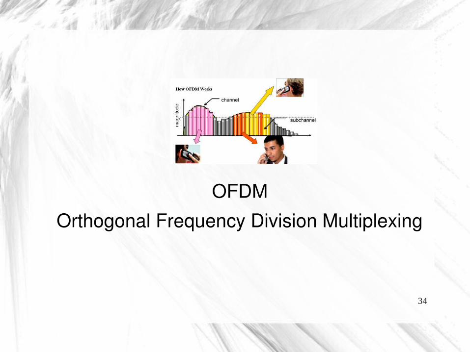
OFDMOrthogonal Frequency Division Multiplexing

35
Intro to OFDM
• 802.11a and 802.11g based on OFDM– Orthogonal Frequency Division Multiplexing
• Revolutionized Wi-Fi and other cellular products by allowing faster throughput and more robustness
• OFDM makes highly efficient use of available spectrum
36
OFDM Based on FDM
• Recall …– Frequency division multiplexing (FDM) transmits
multiple signals simultaneously over single transmission path, such as cable or wireless system
– Each signal travels within its own unique frequency range (carrier)
– What are drawbacks of this technique?

37
FDM• Comment
– FDM transmissions are not efficient since each analog channel can only be used one user at a time
Each User has their own channel

38
Traditional View FDM with Guards
Traditional view of signals carrying modulation
Receiver filter passband: one signal selected
Guards
Guard bands waste the spectrum
Parts of spectrum wasted – need for guard bands to separate the signals

39
OFDM based on FDM
• OFDM, data divided among large number of closely spaced carriers– "frequency division multiplex" part of name– Entire bandwidth from single source of data– Instead of transmitting data serially, data is
transferred in parallel– Divided among multiple subcarriers– Only small amount of data is carried on each carrier

40
OFDM• An OFDM signal consists of
– Several closely spaced modulated carriers– When modulation of any form - voice, data, etc. is
applied to a carrier• Sidebands spread out on either side• A receiver must be able to receive whole signal to be
able to demodulate data• So, when signals are transmitted close to one another
they typically spaced with guard band between them

41
Traditional View FDM with Guards
Traditional view of signals carrying modulation
Receiver filter passband: one signal selected
Guards
Guard bands waste the spectrum
42
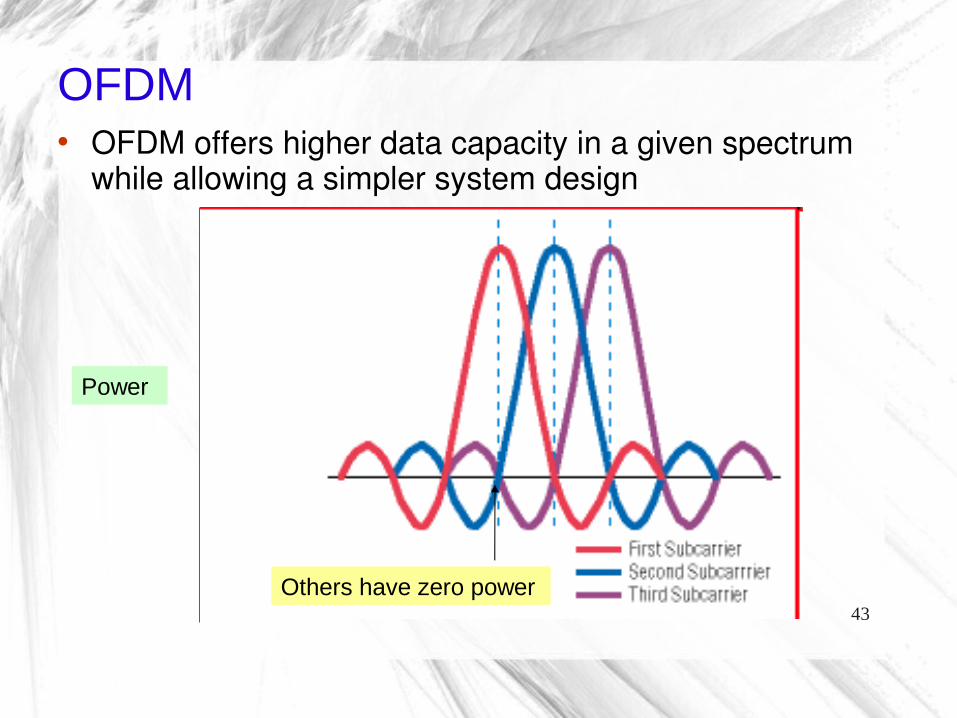
OFDM
• Make Subcarriers Mathematically Orthogonal – Breakthrough for OFDM– Enables OFDM receivers to separate subcarriers
via Fast Fourier Transform (FFT)• Eliminates guard bands• OFDM subcarriers can overlap to make full use of
spectrum• Peak of each subcarrier spectrum, power in all other
subcarriers is zero
43
OFDM• OFDM offers higher data capacity in a given spectrum
while allowing a simpler system design
Others have zero power
Power

44
OFDM
• Shows parallel nature of subcarriers
45
Benefits of OFDM
• Radio signals are imperfect – General challenges of RF signals include
• Signal-to-noise ratio• Self-interference (intersymbol interference or ISI)• Fading owing to multipath effects
– Same signal arrives at a receiver via different paths
–Briefly look at multipath fading …

46
Multipath Fading
• Indoor and Outdoor radio channel is characterized by multipath reception– Sent signal contains not only a direct line-of-sight radio wave,
but also a large number of reflected radio waves– Outdoors line-of-sight often blocked by obstacles, and collection
of differently delayed waves received by mobile antenna– These reflected waves interfere with direct wave, causes
significant degradation link performance
- Waves arrive at slightly different times, so they are out of phase with original wave
• Randomly boosts or cancels out parts of signal

47
Multipath Fading

48
Benefits of OFDM
• Main way to prevent Intersymbol Interference errors– Transmit a short block of data (a symbol)– Wait until all the multipath echoes fade before sending
another symbol– Waiting time often referred to as guard interval

49
Benefits of OFDM
• Longer guard intervals - more robust system to multipath effects– But during guard interval, system gets no use from
available spectrum– Longer the wait, the lower the effective channel
capacity• Some guard interval is necessary for any
wireless system– Goal is to minimize that interval and maximize
symbol transmission time

50
Benefits of OFDM
• OFDM meets this challenge by• Dividing transmissions among multiple
subcarriers– Symbol transmission time is multiplied by number of
subcarriers– For example: With 802.11a, there are 52 channels,
so the system has 52 times transmission capacity compared to single channel
51
Benefits of OFDM
• Using multiple subcarriers also makes OFDM systems more robust to fading– Fading decreases received signal strength at
particular frequencies, so problem affects only a few of the subcarriers at any given time and …
– Error-correcting codes provide redundant information that enables OFDM receivers to restore information lost in these few erroneous subcarriers

52
802.11a

53
Intro to 802.11a
• 802.11a was approved in September 1999, two years after 802.11 standard approved– Operates in 5 GHz Unlicensed National Information
Infrastructure (UNII) band– Spectrum is divided into three “domains,”– Each has restrictions imposed on maximum allowed
output power

54
ISM vs. U-NII

55
802.11a OFDM
• 802.11a specifies• 8 non-overlapping 20 MHz channels in lower two bands
– Each divided into 52 sub-carriers (four of which carry pilot data) of 300-kHz bandwidth each
• 4 non-overlapping 20 MHz channels are specified in upper band
• Receiver processes 52 individual bit streams, reconstructing original high-rate data stream– Four complex modulation methods are employed, depending on
data rate that can be supported by conditions between transmitter and receiver
– Include BPSK, QPSK, 16-QAM, and 64-QAM

56
802.11a Channels
57
Trying to Use 802.11a
• Advantage– Since 2.4 GHz band is heavily used, using 5 GHz
band gives 802.11a advantage of less interference• Disadvantage
– However, high carrier frequency also brings disadvantages
– It restricts use of 802.11a to almost line of sight, necessitating use of more access points
– It also means that 802.11a cannot penetrate as far as 802.11b since it is absorbed more readily, other things (such as power) being equal

58
802.11b vs 802.11a Path Loss
Free Space Path Loss in dB for 2.4 and 5 GHz Spectrums
Distance (miles) 2.4 GHz 5 GHz
0.5 98.36 104.565 104.38 110.581.5 107.91 114.103 113.93 120.124 116.42 122.625 118.36 124.5610 124.38 130.58Loss = 32.4 X 20Log(MHz) X 20Log(distance)

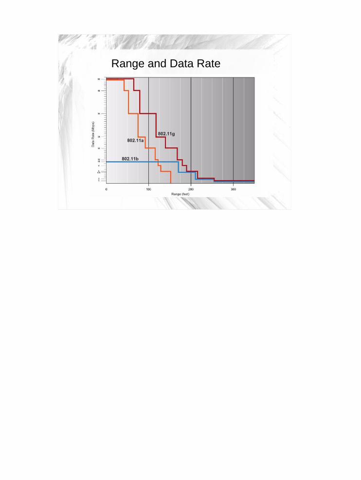
Range and Data Rate

60
802.11g
• June 2003, a third modulation standard ratified– 802.11g– Works in 2.4 GHz band (like 802.11b) – Maximum data rate of 54 Mbit/s– 802.11g hardware works with 802.11b hardware– Older networks, 802.11b node significantly reduces
the speed of an 802.11g network

61
802.11g
• Modulation schemes used in 802.11g– OFDM for data rates of 6, 9, 12, 18, 24, 36, 48, and 54
Mbit/s, and – Reverts to CCK – Complimentary Code Keyinglike 802.11b for 5.5 and 11 Mbit/s – DBPSK/DQPSK+DSSS for 1 and 2 Mbit/s
• Even though 802.11g operates in same frequency band as 802.11b– Achieve higher data rates because it uses OFDM and
better modulation

62
802.11g Rates, Transmission, Modulation
Data Rate Mbps Trans Type Modulation54 OFDM 64 QAM48 OFDM 64 QAM11 DSSS QPSK1 6 OFDM BPSK5.5 DSSS CCK

63
802.11n

64
802.11n
• 802.11n is long anticipated update to WiFi standards 802.11a/b/g– 4x increase in throughput– Improvement in range– 802.11n ratified by IEEE 2009

65
802.11n Features
• 802.11n utilizes larger number of antennas• Number of antennas relates to number of
simultaneous streams– Two receivers and two transmitters (2x2) or four
receivers and four transmitters (4x4)– The standards requirement is a 2x2 with a
maximum two streams, but allows 4x4

66
802.11n Features
• 802.11n standard operates in 2.4-GHz, the 5-GHz radio band, or both – more flexibility– Backward compatibility with preexisting 802.11a/b/g
deployment– Majority of devices and access points deployed are
dual-band• Operates in both 2.4-GHz and 5-GHz frequencies
67
802.11n Features
• Wireless solutions based on 802.11n standard use several techniques to improve throughput, reliability, and predictability of wireless
• Three primary innovations are– Multiple Input Multiple Output (MIMO) technology– Channel bonding (40MHz Channels)– Packet aggregation
• Allows 802.11n solutions to achieve fivefold performance increase over 802.11a/b/g networks
• How does this work?

68
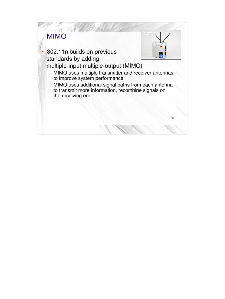
MIMO
• 802.11n builds on previous standards by adding multiple-input multiple-output (MIMO)
– MIMO uses multiple transmitter and receiver antennas to improve system performance
– MIMO uses additional signal paths from each antenna to transmit more information, recombine signals on the receiving end

69
MIMO
• 802.11n access points and clients transmit two or more spatial streams
• Use multiple receive antennas and advanced signal processing to recover multiple transmitted data streams– MIMO-enabled access points use spatial multiplexing to
transmit different bits of a message over separate antennas
– Provides greater data throughput

70
MIMO Technology• Multiple independent streams are transmitted
simultaneously to increase the data rate
71
MIMO
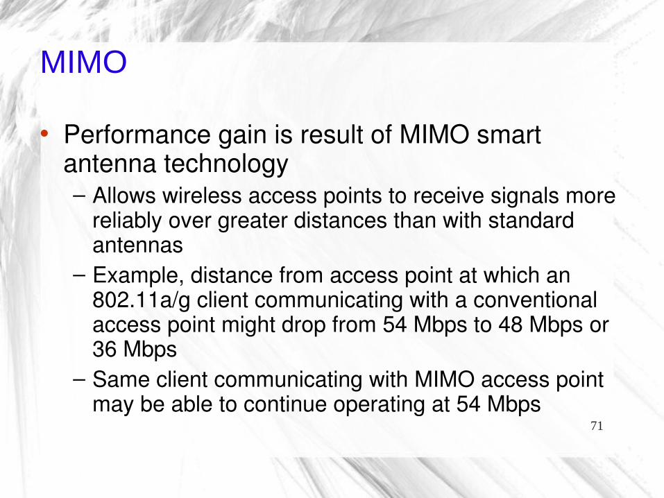
• Performance gain is result of MIMO smart antenna technology– Allows wireless access points to receive signals more
reliably over greater distances than with standard antennas
– Example, distance from access point at which an 802.11a/g client communicating with a conventional access point might drop from 54 Mbps to 48 Mbps or 36 Mbps
– Same client communicating with MIMO access point may be able to continue operating at 54 Mbps
72
Channel Bonding
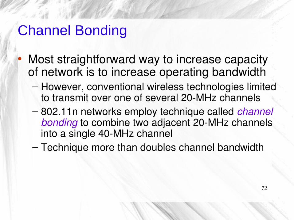
• Most straightforward way to increase capacity of network is to increase operating bandwidth– However, conventional wireless technologies limited
to transmit over one of several 20-MHz channels– 802.11n networks employ technique called channel
bonding to combine two adjacent 20-MHz channels into a single 40-MHz channel
– Technique more than doubles channel bandwidth

73
Channel Bonding
– Channel bonding most effective in 5-GHz frequency given greater number of available channels
• 2.4-GHz frequency has only 3 non-overlapping 20-MHz channels
• Thus, bonding two 20-MHz channels uses two thirds of total frequency capacity
– So, IEEE has rules on when a device can operate in 40MHz channels in 2.4GHz space to ensure optimal performance
– 5 GHz has larger number of channels available for bonding

74
Packet Aggregation
• In conventional wireless transmission methods– Amount of channel access overhead required to
transmit each packet is fixed, regardless of the size of the packet itself
– As data rates increase, time required to transmit each packet shrinks
– Overhead cost remains same

75
Packet Aggregation
• 802.11n technologies increase efficiency by aggregating multiple data packets into a single transmission frame
• 802.11n networks can send multiple data packets with fixed overhead cost of just a single frame
• Packet aggregation is more beneficial for certain types of applications such as file transfers – Real-time applications (e.g. voice) don’t benefit from
packet aggregation because its packets would need to be interspersed at regular intervals
– And combining packets into larger payload would introduce unnecessary latency

76
802.11 Comparison
77
Summary
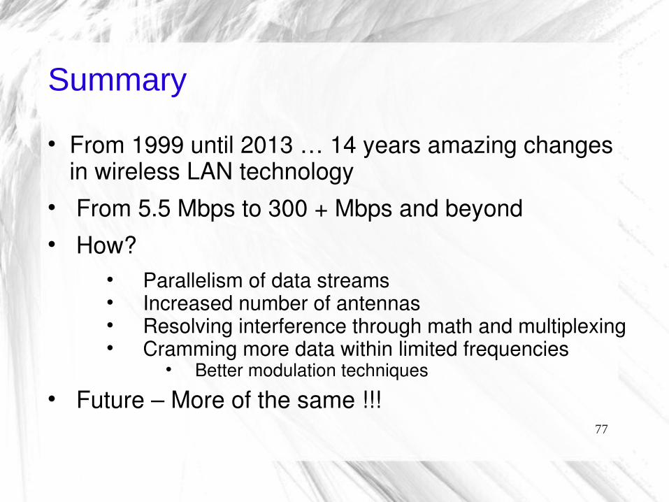
From 1999 until 2013 … 14 years amazing changes in wireless LAN technology
From 5.5 Mbps to 300 + Mbps and beyond How?
Parallelism of data streams Increased number of antennas Resolving interference through math and multiplexing Cramming more data within limited frequencies
Better modulation techniques Future – More of the same !!!

78
End
Assignment 3 – Wireless Questions

1
CSCD 433/533Wireless Networks and Security
Lecture 8Physical Layer, and 802.11 b,g,a,n,ac
Differences
Spring 2016
2
Topics
Differences between 802.11 b,g,a and n− Frequency ranges− Speed
Spread Spectrum Techniques in General DSSS Spread Spectrum, 802.11b OFDM and 802.11n
3
Introduction
Today, discuss physical layer of 802.11 standard
Many techniques have helped to increase throughput as versions evolved over time
We will start with slowest and end with fastest Note, we will not cover 802.11ac

4
FCC Regulation
In 1995, Federal Communications Commission allocated several bands of wireless spectrum for use without license
FCC stipulated that use of spread spectrum technology would be required
Recall, that in 1990, IEEE began exploring a standard for Wireless LAN's
July 1997 initial attempt, in 1999 the 802.11b standard was ratified, first popular version
5
Spread Spectrum Defined
Spread spectrum communication technique that spreads narrowband communication signal over wider range of frequencies for transmission then de-spreads it into original data bandwidth at receiver
Spread spectrum is characterized by Wide bandwidth and Low power
Jamming and Interference have less effect on Spread spectrum because
Resembles noise Hard to detect Hard to intercept

04/15/16 6
5-6
Spread Spectrum Transmission
• Spread Spectrum Transmission– You are required by law to use spread spectrum
transmission in unlicensed bands– Spread spectrum transmission reduces propagation
problems• Especially multipath interference
– Spread spectrum transmission is NOT used for security in WLANs
• Although military does use spread spectrum transmission to make signals hard to detect
• This requires a different spread spectrum technology

7
7
Frequency BandISM: Industry, Science, Medicine
unlicensed frequency spectrum: 900Mhz, 2.4Ghz, 5.7Ghz

8
8
IEEE 802.11 Frequency Band
and 802.11b/g 802.11a802.11 ac
Wavelength

9
802.11 Physical Channels
The 802.11b standard defines 14 frequency channels in 2.4GHz range
− Only eleven are allowed for unlicensed use by the FCC in the US
− Each channel uses "Direct Sequence Spread Spectrum" (DSSS) to spread data over channel that extends 11MHz on each side of center frequency
− Channels overlap, but there are three out of 11 channels that don't
10
10
802.11b/g Channels
2400 – 2483 Each channel spaced 5 MHz apart
Only non-overlapping channels are 1, 6 and 11
Channel Width = 22 MHz Channels – 12 – 14, not sanctioned by FCC

11
Frequency Assignments
Channel 12.412 GHz
Channel 62.437 GHz
Channel 112.462 GHz
25 MHz25 MHz
The Center frequencies of each channel are only 5 Mhz apart but each channel is 22 Mhz wide therefore adjacent channels will overlap.
DSSS systems with overlapping channels in same physical space cause interference between systems.
Co-located DSSS systems should have frequencies which are at least 5 channels apart, e.g., Channels 1 and 6, Channels 2 and 7, etc.
Channels 1, 6 and 11 are the only theoretically non-overlapping channels.

12
Radio Communications
How do you transmit Radio Signals reliably?− Classic approach ….
Confine information carrying signal to a narrow frequency band and pump as much power as possible into signal
Make sure antenna is able to detect signal− Noise occurs as distortion in frequency band− To overcome noise
Ensure power of signal > noise Recall, SNR = Signal to Noise Ratio
But, what if you deliberately include your
own noise into signal?
13
Radio Communications
Given multiple devices compete in ISM bands, how do you reliably transmit data?
− Spread Spectrum is one of the answers− Native radio signals sent with as much power as
allowed over a narrow band of frequency Spread Spectrum
− Used to transform radio signals for data− Uses math functions to diffuse signal over larger
range of frequencies− Makes transmissions look like noise to narrowband
receiver

14
Radio Communications
Spread Spectrum continued− On receiver side, signal is transformed back to
narrow-band and noise is removed− Spread spectrum is a requirement for unlicensed
devices− Minimize interference between unlicensed devices,
FCC imposes limitations on power of transmissions

15
Radio Communications
Trivia Question− Who patented spread spectrum transmission and
when was it patented?
16
Hedy Lamarr
Austrian actress Hedy Lamarr pioneer in field of wireless communications following her emigration to the United States
With co-inventor George Anthiel, developed a "Secret Communications System" to help combat Nazis in World War II
By manipulating radio frequencies at irregular intervals between transmission and reception, invention formed an unbreakable code to prevent classified messages from being intercepted by enemy personnel
Patented in 1941 Her Story http://www.women-inventors.com/Hedy-Lammar.asp

17
Spread Spectrum 802.11 uses three different Spread Spectrum
technologies1. FH – Frequency Hopping (FHSS)
Jumps from one frequency to another in random pattern− Transmits a short burst at each subchannel
2 Mbps FH or FHSS original spread spectrum technology developed in 1997 with 802.11 standard
However, quickly bypassed by more sophisticated spread spectrum technologies
We won’t cover it … can see below
FHSS covered in, http://www.cs.clemson.edu/~westall/851/spread-spectrum.pdf
18
Spread Spectrum Continued
2. DS or DSSS Direct Sequence Took over from FHSS and allowed for faster throughput Used in 802.11b Spreads out signal over a wider path Uses frequency coding functions
3. OFDM – Orthogonal Frequency Division Multiplexing Divides channel into several subchannels and encode a
portion of signal across each subchannel in parallel 802.11a and 802.11g use this technology Allows for even faster throughput than DSSS

19
802.11 Spread Spectrum in General
20
Spread Spectrum Code Techniques
Spread-spectrum is a signal propagation technique
− Employs several methods Decrease potential interference to other
receivers− Generally makes use of noise-like signal structure to
spread normally narrowband signal over relatively wideband (radio) band of frequencies
− Receiver correlates (matches) received signals to retrieve original information signal
21
Spread Spectrum Code Techniques
Three characteristics of Spread Spectrum techniques
1. Signal occupies bandwidth much greater than that is necessary to send the information
2. Bandwidth is spread by means of code independent of data 3. Receiver synchronizes code to recover the data

22
Spread Spectrum Techniques
In a spread-spectrum system, signals spread across wide bandwidth, making them difficult to intercept and demodulate

23
Same code must be known in advance at both ends of the transmission channel
Spread Spectrum Code Techniques
Codes are what DSSS uses … talk about next
Spreading de-Spreading
24
General Model of Spread Spectrum System

25
DSSS and HR/DSSS

26
DSSS
DSSS is a spread spectrum technique− Modulation alters a carrier wave to transmit a data
signal (text, voice, audio, video, etc.) − Phase-modulates a sine wave pseudorandomly
Continuous string of pseudonoise (PN) code symbols called “chips”
Each of which has a shorter duration than an information bit Each information bit is modulated by sequence of much
faster chips

27
DSSS
Why this works ...− To a narrowband receiver, transmitted signal looks like noise− Original signal can be recovered through correlation that
reverses the process− The ratio (in dB) between the spread bandwidth to the
unspread bandwidth is known as processing gain
Example
1 kHz signal is spread to 100 kHz
Process gain would be 100,000/1,000 = 100
In decibels, 10 log10(100) = 20 dB
− Typical SS processing gains run from 10dB to 60dB
28
DSSS
How DSSS works − Apply something called a “chipping” sequence to
the data stream− Chip is a binary digit− But, spread-spectrum developers make distinction
to separate encoding of data from the data itself Talk about data is bits Talk about encoding is chips or chipping sequence
29
DSSS Example
Chipping sequence− Also called Pseudorandom Noise Codes (PNC)− Must run at a higher rate than underlying data− See next slide ...
At left, is a data bit 0 or 1 For each bit, chip sequence is used Chip is an 11 bit code combined with a data bit to
produce an 11 bit code This gets transmitted to receiver

30
DSSS Chipping Sequence Example
Data SpreadingEncoded Data Correlation
1
0
1
0
Modulo 2
add
Spreading Code
10110111000
10110111000
01001000111Modulo 2
Subtract
10110111000
Spreading Code

31
31
Figure 6.33 DSSS example

32
DSSS
Encoding DSSS− 802.11 originally adopted an 11-bit Barker word− Each bit encoded using entire Barker word or
chipping sequence− Key attribute of Barker words
Have good autocorrelation properties− High signal recovery possible when signal
distorted by noise Correlation function operates over wide range of
environments and is tolerant of propagation delay

33
DSSS
Encoding DSSS− Why 11 bits?
Regulatory authorities require a 10 dB processing gain in DSSS systems
Using an 11 bit spreading code for each bit let 802.11 meet regulatory requirements
Recall− The ratio (in dB) between the spread baseband and the
original signal is processing gain
Nice Paper on DSSS
http://www.ni.com/white-paper/4450/en/

34
OFDMOrthogonal Frequency Division Multiplexing
35
Intro to OFDM
• 802.11a and 802.11g based on OFDM– Orthogonal Frequency Division Multiplexing
• Revolutionized Wi-Fi and other cellular products by allowing faster throughput and more robustness
• OFDM makes highly efficient use of available spectrum

36
OFDM Based on FDM
• Recall …– Frequency division multiplexing (FDM) transmits
multiple signals simultaneously over single transmission path, such as cable or wireless system
– Each signal travels within its own unique frequency range (carrier)
– What are drawbacks of this technique?

37
FDM• Comment
– FDM transmissions are not efficient since each analog channel can only be used one user at a time
Each User has their own channel

38
Traditional View FDM with Guards
Traditional view of signals carrying modulation
Receiver filter passband: one signal selected
Guards
Guard bands waste the spectrum
Parts of spectrum wasted – need for guard bands to separate the signals

39
OFDM based on FDM
• OFDM, data divided among large number of closely spaced carriers– "frequency division multiplex" part of name– Entire bandwidth from single source of data– Instead of transmitting data serially, data is
transferred in parallel– Divided among multiple subcarriers– Only small amount of data is carried on each carrier
40
OFDM• An OFDM signal consists of
– Several closely spaced modulated carriers– When modulation of any form - voice, data, etc. is
applied to a carrier• Sidebands spread out on either side• A receiver must be able to receive whole signal to be
able to demodulate data• So, when signals are transmitted close to one another
they typically spaced with guard band between them

41
Traditional View FDM with Guards
Traditional view of signals carrying modulation
Receiver filter passband: one signal selected
Guards
Guard bands waste the spectrum

42
OFDM
• Make Subcarriers Mathematically Orthogonal – Breakthrough for OFDM– Enables OFDM receivers to separate subcarriers
via Fast Fourier Transform (FFT)• Eliminates guard bands• OFDM subcarriers can overlap to make full use of
spectrum• Peak of each subcarrier spectrum, power in all other
subcarriers is zero

43
OFDM• OFDM offers higher data capacity in a given spectrum
while allowing a simpler system design
Others have zero power
Power

44
OFDM
• Shows parallel nature of subcarriers
45
Benefits of OFDM
• Radio signals are imperfect – General challenges of RF signals include
• Signal-to-noise ratio• Self-interference (intersymbol interference or ISI)• Fading owing to multipath effects
– Same signal arrives at a receiver via different paths
–Briefly look at multipath fading …

46
Multipath Fading
• Indoor and Outdoor radio channel is characterized by multipath reception– Sent signal contains not only a direct line-of-sight radio wave,
but also a large number of reflected radio waves– Outdoors line-of-sight often blocked by obstacles, and collection
of differently delayed waves received by mobile antenna– These reflected waves interfere with direct wave, causes
significant degradation link performance
- Waves arrive at slightly different times, so they are out of phase with original wave
• Randomly boosts or cancels out parts of signal

47
Multipath Fading
48
Benefits of OFDM
• Main way to prevent Intersymbol Interference errors– Transmit a short block of data (a symbol)– Wait until all the multipath echoes fade before sending
another symbol– Waiting time often referred to as guard interval

49
Benefits of OFDM
• Longer guard intervals - more robust system to multipath effects– But during guard interval, system gets no use from
available spectrum– Longer the wait, the lower the effective channel
capacity• Some guard interval is necessary for any
wireless system– Goal is to minimize that interval and maximize
symbol transmission time
50
Benefits of OFDM
• OFDM meets this challenge by• Dividing transmissions among multiple
subcarriers– Symbol transmission time is multiplied by number of
subcarriers– For example: With 802.11a, there are 52 channels,
so the system has 52 times transmission capacity compared to single channel
51
Benefits of OFDM
• Using multiple subcarriers also makes OFDM systems more robust to fading– Fading decreases received signal strength at
particular frequencies, so problem affects only a few of the subcarriers at any given time and …
– Error-correcting codes provide redundant information that enables OFDM receivers to restore information lost in these few erroneous subcarriers

52
802.11a

53
Intro to 802.11a
• 802.11a was approved in September 1999, two years after 802.11 standard approved– Operates in 5 GHz Unlicensed National Information
Infrastructure (UNII) band– Spectrum is divided into three “domains,”– Each has restrictions imposed on maximum allowed
output power

54
ISM vs. U-NII

55
802.11a OFDM
• 802.11a specifies• 8 non-overlapping 20 MHz channels in lower two bands
– Each divided into 52 sub-carriers (four of which carry pilot data) of 300-kHz bandwidth each
• 4 non-overlapping 20 MHz channels are specified in upper band
• Receiver processes 52 individual bit streams, reconstructing original high-rate data stream– Four complex modulation methods are employed, depending on
data rate that can be supported by conditions between transmitter and receiver
– Include BPSK, QPSK, 16-QAM, and 64-QAM

56
802.11a Channels

57
Trying to Use 802.11a
• Advantage– Since 2.4 GHz band is heavily used, using 5 GHz
band gives 802.11a advantage of less interference• Disadvantage
– However, high carrier frequency also brings disadvantages
– It restricts use of 802.11a to almost line of sight, necessitating use of more access points
– It also means that 802.11a cannot penetrate as far as 802.11b since it is absorbed more readily, other things (such as power) being equal

58
802.11b vs 802.11a Path Loss
Free Space Path Loss in dB for 2.4 and 5 GHz Spectrums
Distance (miles) 2.4 GHz 5 GHz
0.5 98.36 104.565 104.38 110.581.5 107.91 114.103 113.93 120.124 116.42 122.625 118.36 124.5610 124.38 130.58Loss = 32.4 X 20Log(MHz) X 20Log(distance)
59
Range and Data Rate
60
802.11g
• June 2003, a third modulation standard ratified– 802.11g– Works in 2.4 GHz band (like 802.11b) – Maximum data rate of 54 Mbit/s– 802.11g hardware works with 802.11b hardware– Older networks, 802.11b node significantly reduces
the speed of an 802.11g network

61
802.11g
• Modulation schemes used in 802.11g– OFDM for data rates of 6, 9, 12, 18, 24, 36, 48, and 54
Mbit/s, and – Reverts to CCK – Complimentary Code Keyinglike 802.11b for 5.5 and 11 Mbit/s – DBPSK/DQPSK+DSSS for 1 and 2 Mbit/s
• Even though 802.11g operates in same frequency band as 802.11b– Achieve higher data rates because it uses OFDM and
better modulation

62
802.11g Rates, Transmission, Modulation
Data Rate Mbps Trans Type Modulation54 OFDM 64 QAM48 OFDM 64 QAM11 DSSS QPSK1 6 OFDM BPSK5.5 DSSS CCK

63
802.11n

64
802.11n
• 802.11n is long anticipated update to WiFi standards 802.11a/b/g– 4x increase in throughput– Improvement in range– 802.11n ratified by IEEE 2009

65
802.11n Features
• 802.11n utilizes larger number of antennas• Number of antennas relates to number of
simultaneous streams– Two receivers and two transmitters (2x2) or four
receivers and four transmitters (4x4)– The standards requirement is a 2x2 with a
maximum two streams, but allows 4x4

66
802.11n Features
• 802.11n standard operates in 2.4-GHz, the 5-GHz radio band, or both – more flexibility– Backward compatibility with preexisting 802.11a/b/g
deployment– Majority of devices and access points deployed are
dual-band• Operates in both 2.4-GHz and 5-GHz frequencies

67
802.11n Features
• Wireless solutions based on 802.11n standard use several techniques to improve throughput, reliability, and predictability of wireless
• Three primary innovations are– Multiple Input Multiple Output (MIMO) technology– Channel bonding (40MHz Channels)– Packet aggregation
• Allows 802.11n solutions to achieve fivefold performance increase over 802.11a/b/g networks
• How does this work?
68
MIMO
• 802.11n builds on previous standards by adding multiple-input multiple-output (MIMO)
– MIMO uses multiple transmitter and receiver antennas to improve system performance
– MIMO uses additional signal paths from each antenna to transmit more information, recombine signals on the receiving end

69
MIMO
• 802.11n access points and clients transmit two or more spatial streams
• Use multiple receive antennas and advanced signal processing to recover multiple transmitted data streams– MIMO-enabled access points use spatial multiplexing to
transmit different bits of a message over separate antennas
– Provides greater data throughput

70
MIMO Technology• Multiple independent streams are transmitted
simultaneously to increase the data rate
71
MIMO
• Performance gain is result of MIMO smart antenna technology– Allows wireless access points to receive signals more
reliably over greater distances than with standard antennas
– Example, distance from access point at which an 802.11a/g client communicating with a conventional access point might drop from 54 Mbps to 48 Mbps or 36 Mbps
– Same client communicating with MIMO access point may be able to continue operating at 54 Mbps

72
Channel Bonding
• Most straightforward way to increase capacity of network is to increase operating bandwidth– However, conventional wireless technologies limited
to transmit over one of several 20-MHz channels– 802.11n networks employ technique called channel
bonding to combine two adjacent 20-MHz channels into a single 40-MHz channel
– Technique more than doubles channel bandwidth

73
Channel Bonding
– Channel bonding most effective in 5-GHz frequency given greater number of available channels
• 2.4-GHz frequency has only 3 non-overlapping 20-MHz channels
• Thus, bonding two 20-MHz channels uses two thirds of total frequency capacity
– So, IEEE has rules on when a device can operate in 40MHz channels in 2.4GHz space to ensure optimal performance
– 5 GHz has larger number of channels available for bonding

74
Packet Aggregation
• In conventional wireless transmission methods– Amount of channel access overhead required to
transmit each packet is fixed, regardless of the size of the packet itself
– As data rates increase, time required to transmit each packet shrinks
– Overhead cost remains same

75
Packet Aggregation
• 802.11n technologies increase efficiency by aggregating multiple data packets into a single transmission frame
• 802.11n networks can send multiple data packets with fixed overhead cost of just a single frame
• Packet aggregation is more beneficial for certain types of applications such as file transfers – Real-time applications (e.g. voice) don’t benefit from
packet aggregation because its packets would need to be interspersed at regular intervals
– And combining packets into larger payload would introduce unnecessary latency

76
802.11 Comparison
77
Summary
From 1999 until 2013 … 14 years amazing changes in wireless LAN technology
From 5.5 Mbps to 300 + Mbps and beyond How?
Parallelism of data streams Increased number of antennas Resolving interference through math and multiplexing Cramming more data within limited frequencies
Better modulation techniques Future – More of the same !!!

78
End
Assignment 3 – Wireless Questions