csc418 computer graphics - university of torontokaran/courses/csc418/lectures/l15.pdf · csc418...
TRANSCRIPT

1
CSC418 Computer Graphics
■ Raytracing■ Shadows■ Global Illumination
Local vs. Global Illumination
Local Illumination Models
■ e.g. Phong
■ Model source from a light reflected once off a surface towards the eye
■ Indirect light is included with an ad hoc “ambient” term which is normally constant across the scene
Global Illumination Models
■ e.g. ray tracing or radiosity (both are incomplete)
■ Try to measure light propagation in the scene
■ Model interaction between objects and other objects and objects and their environment

2
All surfaces are not created equal
■ Specular surfaces
– e.g. mirrors, glass balls
– An idealized model provides ‘perfect’ reflection
� Incident ray is reflected back as a ray in a single direction
� No scattering (unrealistic)
■ Diffuse surfaces
– e.g. flat paint, chalk
– Lambertian surfaces
– Incident light is scattered in all directions� Also unrealistic for most surfaces
Categories of light transport
■ Specular-Specular
■ Specular-Diffuse
■ Diffuse-Diffuse
■ Diffuse-Specular

3
Real surfaces are more complex…
Ray Tracing
■ Traces path of specularly reflected or transmitted (refracted) rays through environment
■ Rays are infinitely thin
■ Don’t disperse
■ Signature: shiny objects exhibiting sharp, multiple reflections

4
Ray Tracing
■ Unifies in one framework
– Hidden surface removal
– Shadow computation
– Reflection of light
– Refraction of light– Global specular interaction
Raytracing slides borrowed from…

5
Ray tracing setup
6
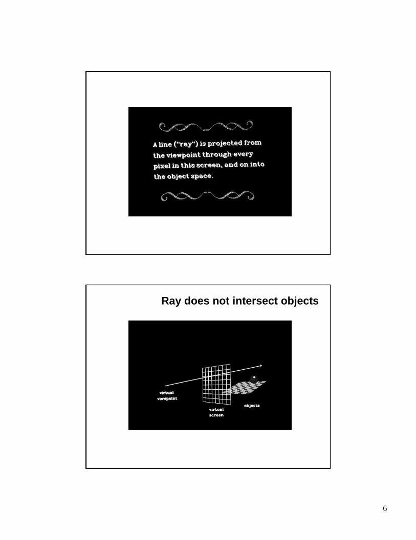
Ray does not intersect objects
7

8
Ray hits object

9
Shadow test
10
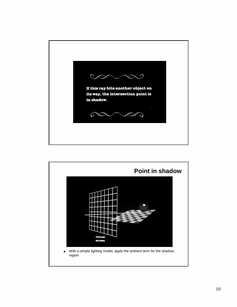
Point in shadow
■ With a simple lighting model, apply the ambient term for the shadow region

11
12
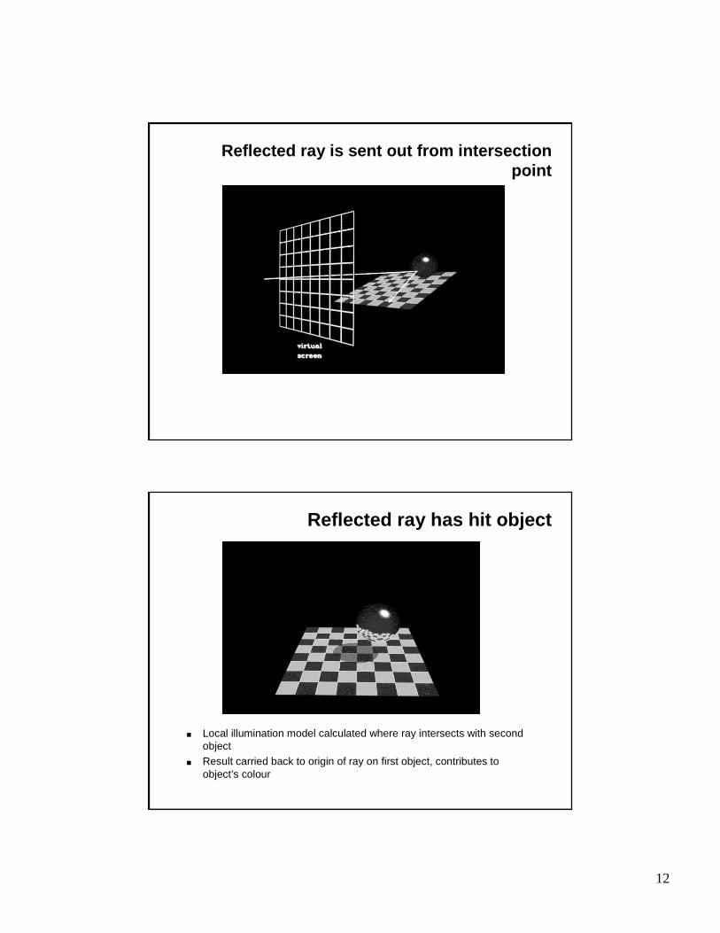
Reflected ray is sent out from intersection point
Reflected ray has hit object
■ Local illumination model calculated where ray intersects with second object
■ Result carried back to origin of ray on first object, contributes to object’s colour

13
Transmitted ray generated for transparent objects
14
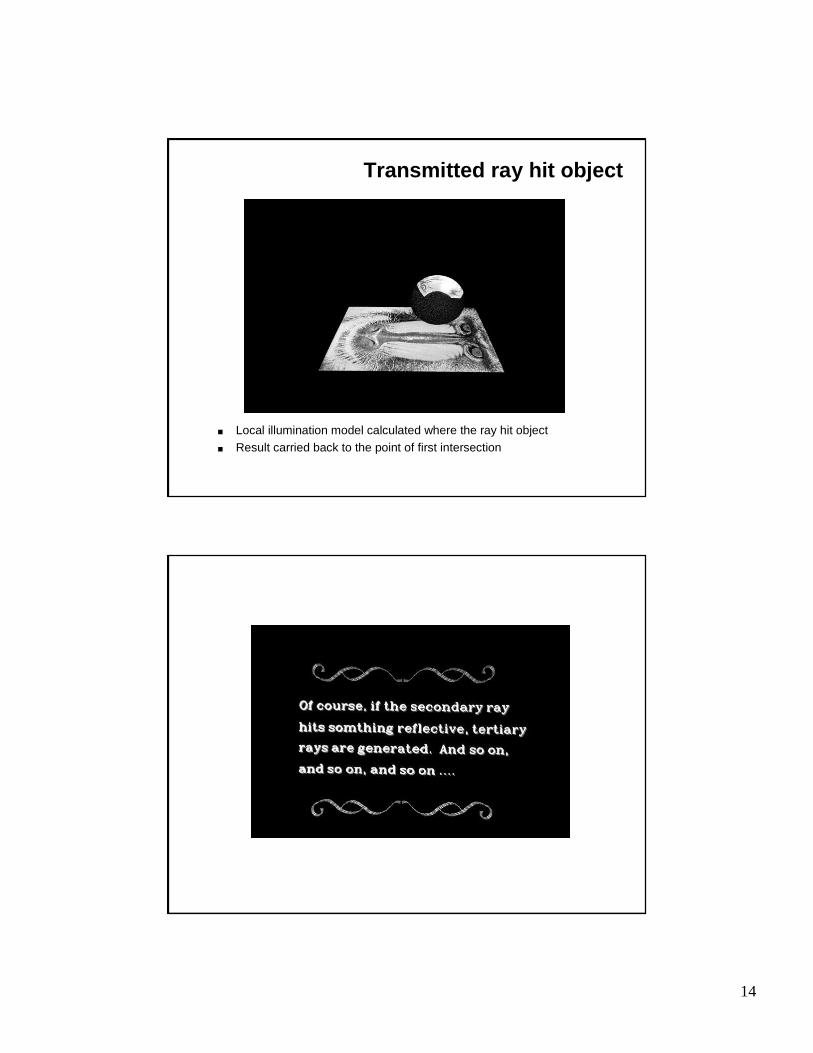
Transmitted ray hit object
■ Local illumination model calculated where the ray hit object■ Result carried back to the point of first intersection

15
No reflection
Single reflection
16
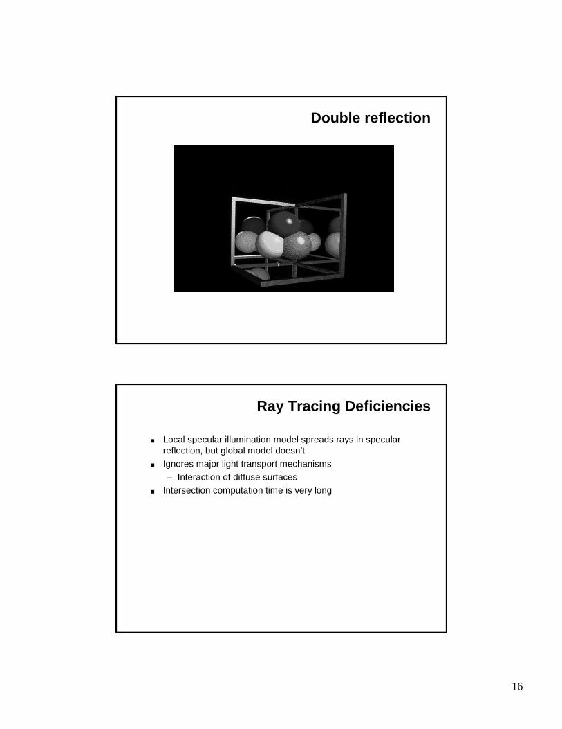
Double reflection
Ray Tracing Deficiencies
■ Local specular illumination model spreads rays in specularreflection, but global model doesn’t
■ Ignores major light transport mechanisms
– Interaction of diffuse surfaces
■ Intersection computation time is very long

17
Ray Tracing Efficiency Improvements
■ Bounding volumes
■ Spatial subdivision
– Octrees
– SEADS
– BSP
Ray Tracing Improvements: Image Quality
■ Backwards ray tracing
– Trace from the light to the surfaces and then from the eye to the surfaces
– “shower” scene with light and then collect it
– “Where does light go?” vs “Where does light come from?”
– Good for caustics
18
Ray Tracing Improvements: Image Quality
■ Cone tracing
– Models some dispersion effects
■ Distributed Ray Tracing
– Super sample each ray
– Blurred reflections, refractions– Soft shadows
– Depth of field
– Motion blur
Radiosity
■ Diffuse interaction within a closed environment
■ Theoretically sound
■ View independent
■ No specular interactions

19
Global Illumination
Direct light is only part of the story

20
Ambient light
Lambertian Reflection and Colour Bleeding

21
Radiosity
Radiosity Equation
22
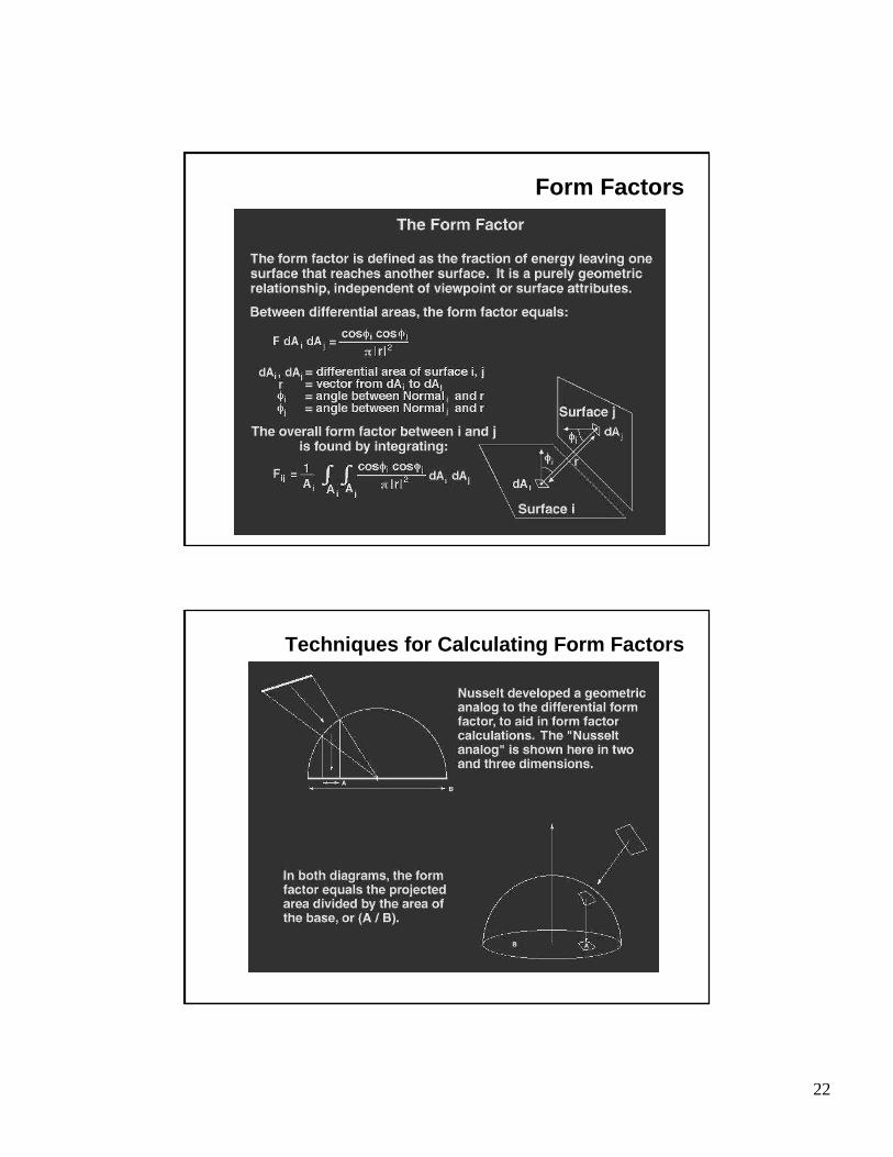
Form Factors
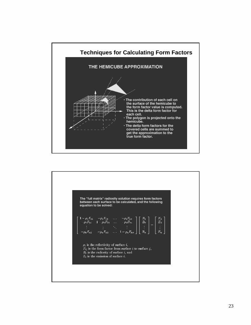
Techniques for Calculating Form Factors
23
Techniques for Calculating Form Factors

24

25

26
Where to next?
■ The general rendering equation (not part of this course!)
■ Next class…Curves and Surfaces