csa-2120 cst-2120 public address system operation manual
TRANSCRIPT

CSA-2120CST-2120
Public Address SystemOperation Manual
CSA-2120 Amplifier & CST-2120 Transformer
CS Commercial Solution Series
2
IMPORTANT SAFETY INFORMATION
WARNING FOR YOUR PROTECTIONREAD THE FOLLOWING:
KEEP THESE INSTRUCTIONS
HEED ALL WARNINGS
FOLLOW ALL INSTRUCTIONS
THE APPARATUS SHALL NOT BE EXPOSED TO DRIPPING OR SPLASHING LIQUID AND NO OBJECT FILLED WITH LIQUID, SUCH AS VASES, SHALL BE PLACED ON THE APPARATUS
CLEAN ONLY WITH A DRY CLOTH.
DO NOT BLOCK ANY OF THE VENTILATION OPENINGS. INSTALL IN ACCORDANCE WITH THE MANUFACTURER’S INSTRUCTIONS.
DO NOT INSTALL NEAR ANY HEAT SOURCES SUCH AS RADIATORS, HEAT REGISTERS, STOVES, OR OTHER APPARATUS (INCLUDING AMPLIFIERS) THAT PRODUCE HEAT.
ONLY USE ATTACHMENTS/ACCESSORIES SPECIFIED BY THE MANUFACTURER.
UNPLUG THIS APPARATUS DURING LIGHTNING STORMS OR WHEN UNUSED FOR LONG PERIODS OF TIME.
Do not defeat the safety purpose of the polarized or grounding-type plug. A polarized plug has two blades with one wider than the other. A grounding type plug has two blades and a third grounding prong. The wide blade or third prong are provided for your safety. If the provided plug does not fit your outlet, consult an electrician for replacement of the obsolete outlet.
Protect the power cord from being walked on or pinched particularly at plugs, convenience receptacles, and the point where they exit from the apparatus.
Use only with the cart stand, tripod bracket, or table specified by the manufacture, or sold with the apparatus. When a cart is used, use caution when moving the cart/apparatus combination to avoid injury from tip-over. Refer all servicing to to qualified service personnel. Servicing is required when the apparatus has been damaged in any way, such as power-supply cord or plug is damaged, liquid has been spilled or objects have fallen into the apparatus, the apparatus has been exposed to rain or moisture, does not operate normally, or has been dropped.
POWER ON/OFF SWITCH: For products provided with a power switch, the power switch DOES NOT break the connection from the mains.
MAINS DISCONNECT: The plug shall remain readily operable. For rack-mount or installation where plug is not accessible, an all-pole mains switch with a contact separation of at least 3 mm in each pole shall be incorporated into the electrical installation of the rack or building.
FOR UNITS EQUIPPED WITH EXTERNALLY ACCESSIBLE FUSE RECEPTACLE: Replace fuse with same type and rating only.
MULTIPLE-INPUT VOLTAGE: This equipment may require the use of a different line cord, attachment plug, or both, depending on the available power source at installation. Connect this equipment only to the power source indicated on the equipment rear panel. To reduce the risk of fire or electric shock, refer servicing to qualified service personnel or equivalent.
If connected to 240V supply, a suitable CSA/UL certified power cord shall be used for this supply.
SAFETY INSTRUCTIONS
NOTICE FOR CUSTOMERS IF YOUR UNIT IS EQUIPPED WITH A POWER CORD.
WARNING: THIS APPLIANCE SHALL BE CONNECTED TO A MAINS SOCKET OUTLET WITH A PROTECTIVE EARTHING CONNECTION.
The cores in the mains lead are coloured in accordance with the following code:
GREEN and YELLOW - Earth BLUE - Neutral BROWN - Live
As colours of the cores in the mains lead of this appliance may not cor-respond with the coloured markings identifying the terminals in your plug, proceed as follows:
• The core which is coloured green and yellow must be connected to the terminal in the plug marked with the letter E, or with the earth symbol, or coloured green, or green and yellow.
• The core which is coloured blue must be connected to the terminal marked N or coloured black.
• The core which is coloured brown must be connected to the terminal marked L or coloured red.
This equipment may require the use of a different line cord, attachment plug, or both, depending on the available power source at installation. If the attachment plug needs to be changed, refer servicing to qualified ser-vice personnel who should refer to the table below. The green/yellow wire shall be connected directly to the units chassis.
CONDUCTORWIRE COLOUR
Normal Alt
L LIVE BROWN BLACK
N NEUTRAL BLUE WHITE
E EARTH GND GREEN/YEL GREEN
WARNING: If the ground is defeated, certain fault conditions in the unit or in the system to which it is connected can result in full line voltage between chassis and earth ground. Severe injury or death can then result if the chassis and earth ground are touched simultaneously.
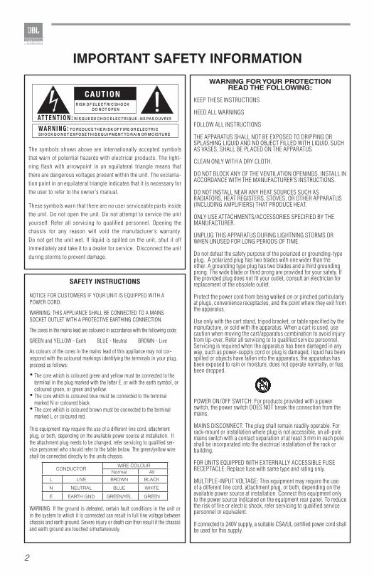
The symbols shown above are internationally accepted symbols that warn of potential hazards with electrical products. The light-ning flash with arrowpoint in an equilateral triangle means that there are dangerous voltages present within the unit. The exclama-tion point in an equilateral triangle indicates that it is necessary for the user to refer to the owner’s manual.
These symbols warn that there are no user serviceable parts inside the unit. Do not open the unit. Do not attempt to service the unit yourself. Refer all servicing to qualified personnel. Opening the chassis for any reason will void the manufacturer’s warranty. Do not get the unit wet. If liquid is spilled on the unit, shut it off immediately and take it to a dealer for service. Disconnect the unit during storms to prevent damage.
3
IMPORTANT SAFETY INFORMATION IMPORTANT SAFETY INFORMATION
ELECTROMAGNETIC
COMPATIBILITY
This device complies with part 15 of the FCC Rules and the Product specifications noted on the Declaration of Conformity. Operation is subject to the following two conditions:
• this device may not cause harmful interference, and
• this device must accept any interference received, including interference that may cause undesired operation.
Operation of this unit within significant electromagnetic fields should be avoided.
• use only shielded interconnecting cables.
U.K. MAINS PLUG WARNING
A molded mains plug that has been cut off from the cord is unsafe. Discard the mains plug at a suitable disposal facility. NEVER UNDER ANY CIRCUMSTANCES SHOULD YOU INSERT A DAMAGED OR CUT MAINS PLUG INTO A 13 AMP POWER SOCKET. Do not use the mains plug without the fuse cover in place. Replacement fuse covers can be obtained from your local retailer. Replacement fuses are 13 amps and MUST be ASTA approved to BS1362.
If you want to dispose this product, do not mix it with gen-eral household waste. There is a separate collection system for used electronic products in accordance with legislation that requires proper treatment, recovery and recycling.
Private household in the 25 member states of the EU, in Switzerland and Norway may return their used electronic products free of charge to designated collection facilities or to a retailer (if you purchase a similar new one).
For Countries not mentioned above, please contact your local authorities for a correct method of disposal.
By doing so you will ensure that your disposed product undergoes the necessary treatment, recovery and recycling and thus prevent potential negative effects on the environment and human health.
MAGNETIC FIELD
CAUTION! Do not locate sensitive high-gain equipment such as preamplifiers or tape decks directly above or below the unit. Because this amplifier has a high power density, it has a strong magnetic field which can induce hum into unshielded devices that are located nearby. The field is strongest just above and below the unit.
If an equipment rack is used, we recommend locating the amplifier(s) in the bottom of the rack and the preamplifier or other sensitive equipment at the top.
4
EC - DECLARATION OF CONFORMITY
Brand: JBLEquipment Type: Amplifier and TransformerModel names: CSA-2120, CST-2120
We, Harman International, declare under our sole responsibility that the product, to which this declaration relates, is in conformity with the following standards.
Due to line current harmonics, we recommend that you contact your supply authority before connection.
We certify that the product identified above conforms to the requirements of the EMC Council Directive 89/336/EEC as amended by 92/31/EEC, and the Low Voltage Directive 73/23/EES as amended by 93/68/EEC.
Report No. Description
EN 55103-1:1997 EMC Compatibility – Product Family Standard for Audio, Video, Audio-Visual and Entertainment Lighting Control Apparatus for Professional Use, Part 1: Emissions
EN 55103-1:1997 Magnetic Field Emissions – Annex A @ 10cm and 20cm
EN 61000-3-2:2005 & AMD1:2008
Limits for Harmonic Current Emissions (equipment input current less than or equal to 16A
EN 61000-3-3:2008 Limitation of Voltage Fluctuations and Flicker in Low-Voltage Supply systems Rated Current less than or equal to 16A
EN 55022:2010 Limits and Methods of Measurement of Radio Disturbance Characteristics of ITE: Radiated & Conducted, Class B Limits
EN 55103-2:1997 EMC Compatibility – Product Family Standard for Audio, Video, Audio-Visual and Entertainment Lighting Control Apparatus for Professional Use, Part 2: Immunity
EN 61000-4-2:2001 Electrostatic Discharge Immunity (Environment E2-Criteria B, 4k V Contact, 8k V Air Discharge)
EN 61000-4-3:2006 Radiated, Radio-Frequency, EMC Immunity (Environment E2, Criteria A)
EN 61000-4-4:2007 Electrical Fast Transient/Burst Immunity (Criteria B)
EN 61000-4-5:2006 Surge Immunity (Criteria B)
EN 61000-4-6:2006 Immunity to Conducted Disturbances Induced by Radio-Frequency Fields (Criteria A)
EN 61000-4-11:2001 Voltage Dips, Short Interruptions and Voltage Variation
Safety Standard:
IEC 60065:2001 – 7th Ed. & AMD1:2005
Safety Requirements – Audio, Video, and Similar Electronic Apparatus
European Representative’s Name and Address:
David Budge10 Harvest CloseYateley, GU46 6YSUnited Kingdom
Responsible for the technical documentation is:
Wilson [email protected]
5
1.0 Welcome
The JBL® CSA-2120 power amplifier is a professional tool designed and built for installed sound applications. The amplifier is a two-channel model providing simple analog amplification, with a switch-mode universal power supply.
The amplifier includes a rack mounting kit. A transformer module can be purchased for use in high impedance distributed sound systems. With the rack mounting kit, you can install the amplifier to a cabinet or wall. If your loudspeaker system requires higher impedance, the transformer module can be connected between the amplifier and loudspeaker systems to obtain the impedance matching.
1.1 Features
• High power output, compact size, light weight
• Accurate, uncoloured sound with very low distortion for the best in music and voice
• Over heat auto protection
• Low voltage auto protection
• Auto-Standby mode
• Detachable Euroblock input and output
• Switch-mode universal power supply
1.2 How to Use This Manual
This manual provides you with necessary information to safely and correctly setup and operate your amplifier. It does not cover every aspect of installation, setup or operation that might occur under every condition.
We strongly recommend you read all instructions, warnings and cautions contained in this manual.
6
2.0 Setup
2.1 Unpacking Your Amplifier
Please unpack and inspect your amplifier for any damage that may have occurred during transit. If damage is found, notify the transportation company immediately. Only you can initiate a claim for shipping damage. We will be happy to help as needed. Save the shipping carton as evidence of damage for the shipper’s inspection.
We also recommend that you save all packing materials so you will have them if you ever need to transport the unit. Never ship the unit without the factory pack.
WARNING: Before you start to set up your amplifier, make sure you read and observe the Important Safety Instructions found at the beginning of this manual.
2.2 Installing Your Amplifier
CAUTION: Before you begin, make sure your amplifier is disconnected from the power source and all level controls turned completely down (counterclockwise).
To install the amplifier, you can use one of the following approaches:
• Rack mount the amplifier with the rack mounting kit, see Figure 2.2.3 and Figure 2.2.4.
• Install the amplifer to the wall with the mounting kit, see Figure 2.2.5.
• Stack amps without using a cabinet. For amplifier dimensions, see Figure 2.2.1.
NOTE: When transporting, amplifiers should be supported at front.

7
Solution A: Rack Mounting an Amplifier and CST-2120 Transformer Module
To install an amplifier and a CST-2120 transformer module in your cabinet system, refer to Figure 2.2.3 and follow the steps below:
1. Align two modules side by side, with the front panel towards the same direction.
2. Connect them with the flat bracket.
3. Attach an angle bracket to each side of the amplifier assembly with screws.
4. Install the amplifier assembly into the cabinet. For details of installation in the chassis of the cabinet, refer to the user guide of your cabinet.
Figure 2.2.1 Dimensions
Figure 2.2.2 Mounting Kit
long angle bracket
flat bracket
angle bracket
Unit: mm [inches]
Figure 2.2.3 Rack mounting an amplifier and CST-2120 Transformer Module
8
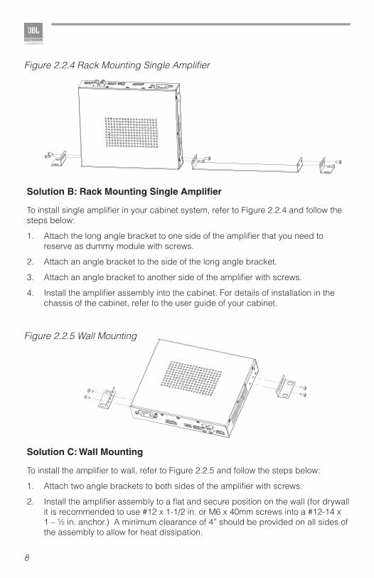
Solution B: Rack Mounting Single Amplifier
To install single amplifier in your cabinet system, refer to Figure 2.2.4 and follow the steps below:
1. Attach the long angle bracket to one side of the amplifier that you need to reserve as dummy module with screws.
2. Attach an angle bracket to the side of the long angle bracket.
3. Attach an angle bracket to another side of the amplifier with screws.
4. Install the amplifier assembly into the cabinet. For details of installation in the chassis of the cabinet, refer to the user guide of your cabinet.
Solution C: Wall Mounting
To install the amplifier to wall, refer to Figure 2.2.5 and follow the steps below:
1. Attach two angle brackets to both sides of the amplifier with screws.
2. Install the amplifier assembly to a flat and secure position on the wall (for drywall it is recommended to use #12 x 1-1/2 in. or M6 x 40mm screws into a #12-14 x 1 – ½ in. anchor.) A minimum clearance of 4” should be provided on all sides of the assembly to allow for heat dissipation.
Figure 2.2.4 Rack Mounting Single Amplifier
Figure 2.2.5 Wall Mounting
9
2.3 Ensuring Proper CoolingWhen using an equipment rack, mount units directly on top of each other. DO NOT block side air vents. The back of the rack should be open.
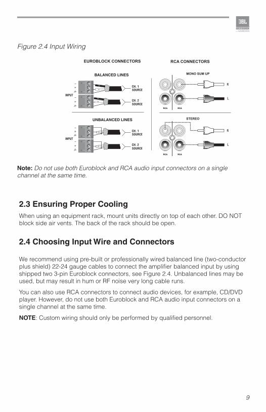
2.4 Choosing Input Wire and Connectors
We recommend using pre-built or professionally wired balanced line (two-conductor plus shield) 22-24 gauge cables to connect the amplifier balanced input by using shipped two 3-pin Euroblock connectors, see Figure 2.4. Unbalanced lines may be used, but may result in hum or RF noise very long cable runs.
You can also use RCA connectors to connect audio devices, for example, CD/DVD player. However, do not use both Euroblock and RCA audio input connectors on a single channel at the same time.
NOTE: Custom wiring should only be performed by qualified personnel.
Figure 2.4 Input Wiring
Note: Do not use both Euroblock and RCA audio input connectors on a single channel at the same time.
10
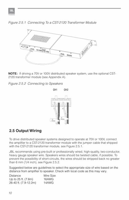
2.5 Output Wiring
To drive distributed speaker systems designed to operate at 70V or 100V, connect the amplifier to a CST-2120 transformer module with the jumper cable that shipped with the CST-2120 transformer module, see Figure 2.5.1.
JBL recommends using pre-built or professionally wired, high-quality, two-conductor, heavy gauge speaker wire. Speakers wires should be twisted cable, if possible. To prevent the possibility of short-circuits, the wires should be stripped back no greater than 6 mm (1/4 inch), see Figure 2.5.2.
Suggested below are guidelines to select the appropriate size of wire based on the distance from amplifier to speaker. Check with local code as this may vary.Distance Wire SizeUp to 25 ft. (7.6m) 16AWG26-40 ft. (7.9-12.2m) 14AWG
Figure 2.5.1 Connecting To a CST-2120 Transformer Module
NOTE: If driving a 70V or 100V distributed speaker system, use the optional CST-2120 transformer module (see Appendix A).
TOSpeaker
TOSpeaker
Figure 2.5.2 Connecting to Speakers
11
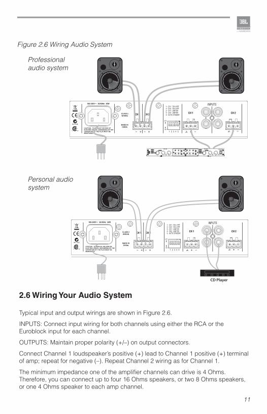
2.6 Wiring Your Audio System
Typical input and output wirings are shown in Figure 2.6.
INPUTS: Connect input wiring for both channels using either the RCA or the Euroblock input for each channel.
OUTPUTS: Maintain proper polarity (+/–) on output connectors.
Connect Channel 1 loudspeaker’s positive (+) lead to Channel 1 positive (+) terminal of amp; repeat for negative (–). Repeat Channel 2 wiring as for Channel 1.
The minimum impedance one of the amplifier channels can drive is 4 Ohms. Therefore, you can connect up to four 16 Ohms speakers, or two 8 Ohms speakers, or one 4 Ohms speaker to each amp channel.
Figure 2.6 Wiring Audio System
Professional audio system
Personal audio system
12
2.7 Connecting to AC Mains
Connect your amplifier to the AC mains power source (power outlet) with the supplied AC power cord. First, connect the IEC end of the cord set to the IEC connector on the amplifier; then, plug the other end of the cord set to the AC mains.
WARNING: The third prong of this connector (ground) is an important safety feature. Do not attempt to disable this ground connection by using an adapter or other methods.
Amplifiers don’t create energy. The AC mains voltage and current must be sufficient to deliver the power you expect. You must operate your amplifier from an AC mains power source with not more than a 10% variation above or below the specified line voltage and within the specified frequency range indicated on the back panel of the amplifier. If you are unsure of the output voltage of your AC mains, please consult your electrician.
2.8 Protecting Your Speakers
It’s wise to avoid clipping the amplifier signal. Not only does clipping sound bad, it can damage high-frequency drivers. The built-in clip limiter prevents clipping.
Also, avoid sending strong subsonic signals to the amplifier. High-level, low-frequency signals from breath pops or dropped microphones can blow out drivers. You can switch on the highpass filters, and this avoids to send subsonic signals under 70 Hz to the amplifier. Use of the high-pass filter is necessary when using the CST2120 transformer module to drive a 70V or 100V distributed loudspeaker system in order to prevent distortion due to transformer saturation.
2.9 Startup Procedure
Use the following procedure when first turning on your amplifier:1. Turn down the level of your audio source.2. Turn down the level controls of the amplifier.3. Power up the amplifier. The Power indicator should light.4. Turn up the level of your audio source to an optimum level.5. Turn up the Level controls on the amplifier until the desired loudness or power
level is achieved.
If you ever need to make any wiring or installation changes, don’t forget to disconnect the power cord.
13
3.0 Operation
3.1 Precautions
Your amplifier is protected from internal and external faults, but you should still take the following precautions for optimum performance and safety:
1. Before use, your amplifier first must be configured for proper operation, including input and output wiring hookup. Improper wiring can result in serious operating difficulties.For information on wiring and configuration, please consult the Setup section of this manual.
2. Use care when making connections, selecting signal sources and controlling the output level.
3. Do not short the ground lead of an output cable to the input signal ground. This may form a ground loop and cause oscillations.
4. WARNING: Never connect the output to a power supply, battery or power main. Electrical shock may result.
5. Tampering with the circuitry, or making unauthorized circuit changes may be hazardous and invalidates all agency listings.
6. Do not operate the amplifier with the red Clip LEDs constantly flashing.7. Do not overdrive the mixer, which will cause clipped signal to be sent to
the amplifier. Such signals will be reproduced with extreme accuracy, and loudspeaker damage may result.
8. Do not operate the amplifier with less than the rated load impedance. Due to the amplifier’s output protection, such a configuration may result in premature clipping and speaker damage.
9. Use the amplifier in a well-ventilated environment and do not use it in ambient temperature conditions in excess of 40ºC. Failure to do so will result in the auto disconnection from power supply, and the overheat auto protection function will be activated. The power indicator will be turned off and there will not be any audio signal coming out of the amplifier. In this case, turn down the volume to the minimum, and the amplifier will resume working. When the amplifier returns to normal temperature then you may turn the volume up to the required level.
10. If the line voltage to the amplifier is too low, the low voltage protection function will be activated. The power indicator will be turned off.
CAUTION: JBL is not liable for damage that results from overdriving other system components.
14
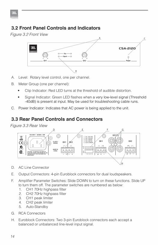
3.2 Front Panel Controls and Indicators
A. Level: Rotary level control, one per channel.
B. Meter Group (one per channel):
• Clip Indicator: Red LED turns at the threshold of audible distortion.
• Signal Indicator: Green LED flashes when a very low-level signal (Threshold -40dB) is present at input. May be used for troubleshooting cable runs.
C. Power Indicator: Indicates that AC power is being applied to the unit.
3.3 Rear Panel Controls and Connectors
D. AC Line Connector
E. Output Connectors: 4-pin Euroblock connectors for dual loudspeakers.
F. Amplifier Parameter Switches: Slide DOWN to turn on these functions. Slide UP to turn them off. The parameter switches are numbered as below:1. CH1 70Hz highpass filter2. CH2 70Hz highpass filter3. CH1 peak limiter4. CH2 peak limiter5. Auto-Standby
G. RCA Connectors
H. Euroblock Connectors: Two 3-pin Euroblock connectors each accept a balanced or unbalanced line-level input signal.
A C
B
D E F G
H
Figure 3.3 Rear View
Figure 3.2 Front View
15
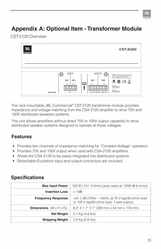
Appendix A: Optional Item - Transformer Module
The rack-mountable JBL Commercial® CST-2120 transformer module provides impedance and voltage matching from the CSA-2120 amplifier to drive 70V and 100V distributed speakers systems.
This unit allows amplifiers without direct 70V or 100V output capability to drive distributed speaker systems designed to operate at those voltages.
Features
• Provides two channels of impedance matching for “Constant-Voltage” operation• Provides 70V and 100V output when used with CSA-2120 amplifiers• Allows the CSA-2120 to be easily integrated into distributed systems• Detachable Euroblock input and output connectors are included.
CST-2120 Overview
Max Input Power: 120 W / CH. 31Vrms (amp rated at 120W @ 8 ohms)
Insertion Loss: < 1dB
Frequency Response: +0/–1 dB (70Hz – 15kHz, at 70 V tap/40 ohms load or 100 V tap/80 ohms load, 1 watt output)
Dimensions (W x H x D) : 8.2” X 1.7” X 7” (209 mm x 44 mm x 178 mm)
Net Weight: 2.1 Kg (4.6 lbs)
Shipping Weight: 2.5 Kg (5.6 lbs)
Specifications
16
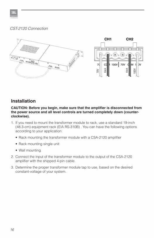
InstallationCAUTION: Before you begin, make sure that the amplifier is disconnected from the power source and all level controls are turned completely down (counter-clockwise).
1. If you need to mount the transformer module to rack, use a standard 19-inch (48.3-cm) equipment rack (EIA RS-310B) . You can have the following options according to your application:
• Rack mounting the transformer module with a CSA-2120 amplifier
• Rack mounting single unit
• Wall mounting
2. Connect the input of the transformer module to the output of the CSA-2120 amplifier with the shipped 4-pin cable.
3. Determine the proper transformer module tap to use, based on the desired constant-voltage of your system.
CST-2120 Connection
17
Output Power (two channels at 1 kHz power, THD+N<0.5%):
4 Ohms 120 W 8 Ohms 120 W
Frequency Response (1 watt into 4 or 8 Ohms):
+1/-1 dB
Load Impedance: Rated for 4 or 8 Ohms
Sensitivity (8 Ohms load): 1.4 Vrms
Signal to Noise Ratio (below rated 8-Ohm power at 1 kHz, A weighted):
>100 dB
Crosstalk (Below rated power): >70dB from 20Hz to 1kHz; >50dB at 20kHz
Input Impedance (nominal): Balanced: 20 k Ohms Unbalanced: 10 k Ohms
AC Line Voltage and Frequency Configurations Available:
100-240 V, 50/60 Hz
Maximum Input Signal: +20 dBu typical
Operating Temperature: 0° C to 40° C at 95% relative humidity (non-condensing)
Auto-Standby: Auto-Standby recovery time: <1ms Auto-Standby recovery threshold: – 60dBu
Dimensions (W x H x D) : 8.2” x 1.7 x 7” (209 mm x 44 mm x 178 mm)
Net Weight: 1 kg (2.1 lbs)
Shipping Weight: 1.7 kg (3.8 lbs)
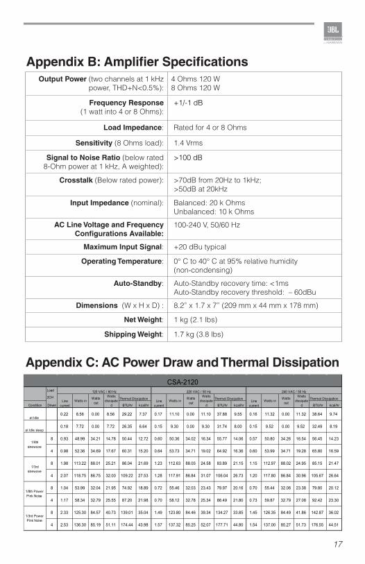
Appendix C: AC Power Draw and Thermal Dissipation
Appendix B: Amplifier Specifications

18
Appendix D: Contact Information
For additional information, please consult JBL Professional Customer Service, your system installer or retailer.
On The World Wide Web:www.jblcommercialproducts.com
Professional Contacts, Outside the USA:Contact the JBL Professional Distributor in your area. A complete list of JBL Professional international distributors is provided at our U.S.A. Website: www.jblpro.com

CSA-2120CST-2120
Sistema de megafoníaManual de operación
Amplificador CSA-2120 y Transformador CST-2120
Serie Soluciones Comerciales CS
ESPAÑOL
20
1.0 Bienvenido
El amplificador CSA-2120 de JBL® es una herramienta profesional diseñada y construida para aplicaciones de sonido instaladas. El amplificador es un modelo de dos canales que ofrece una amplificación analógica simple, con una alimentación universal de modo de interruptor.
El amplificador incluye un kit de montaje en bastidor. Puede adquirirse un módulo transformador para usarlo en sistemas de sonido distribuido de impedancia alta. Con el kit de montaje en bastidor, puede instalar el amplificador en un mueble o en la pared. Si su sistema de altavoces requiere una impedancia alta, el módulo del transformador puede conectarse entre el amplificador y los sistemas de altavoces para obtener la impedancia necesaria.
1.1 Características
• Alta potencia de salida, tamaño compacto, peso ligero
• Sonido puro y exacto, con una distorsión muy baja para conseguir lo mejor en música y voz
• Autoprotección para sobrecalentamientos
• Autoprotección para corriente baja
• Modo de descanso automático
• Entrada y salida Euroblock desmontable
• Alimentación universal con modo de interruptor
1.2 Cómo usar este manual
El presente manual le ofrece la información necesaria para configurar y utilizar de forma segura y correcta su amplificador. No cubre la totalidad de los aspectos de la instalación, configuración y funcionamiento que pueden aparecer en cualquier condición.
Recomendamos encarecidamente que lea todas las instrucciones, advertencias y avisos contenidos en el presente manual.

21
2.0 Configuración
2.1 Desempaque su amplificador
Rogamos extraiga e inspeccione el amplificador en busca de daños que puedan haberse producido durante su transporte. En caso de encontrar algún daño, notifíquelo de inmediato a la empresa de transportes. Sólo usted puede presentar una reclamación por daños durante el envío. Estaremos encantados de ayudarle en todo lo necesario. Guarde la caja de envío como prueba del daño para la inspección del transportista.
También le recomendamos guardar todos los materiales del embalaje para que pueda tenerlos a mano si necesita transportar la unidad. No envíe nunca la unidad sin el embalaje de fábrica.
ADVERTENCIA: Antes de empezar a configurar su amplificador, asegúrese de leer y seguir las instrucciones de seguridad importantes que aparecen al principio del presente manual.
2.2 Instale su amplificador
ADVERTENCIA: Antes de empezar, asegúrese de que su amplificador está desconectado del suministro eléctrico y que todos los controles de niveles están al mínimo (gírelos en el sentido contrario de las agujas del reloj).
• Para instalar el amplificador, tiene varias opciones:Montar en bastidor el amplificador con el kit de montaje en bastidor, vea las figuras 2.2.3 y 2.2.4.
• Instalar el amplificador en la pared con el kit de montaje, vea la figura 2.2.5.
• Apilar amplificadores sin usar ningún mueble. Para conocer las dimensiones del amplificador, vea la figura 2.2.1.
NOTA: Durante el transporte, los amplificadores deberán mantenerse sujetos por delante.
22
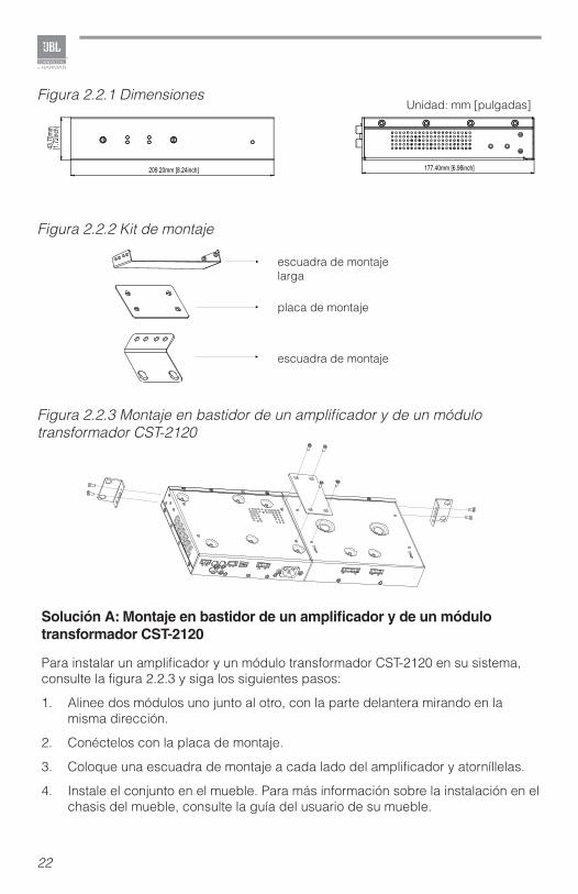
Solución A: Montaje en bastidor de un amplificador y de un módulo transformador CST-2120
Para instalar un amplificador y un módulo transformador CST-2120 en su sistema, consulte la figura 2.2.3 y siga los siguientes pasos:
1. Alinee dos módulos uno junto al otro, con la parte delantera mirando en la misma dirección.
2. Conéctelos con la placa de montaje.
3. Coloque una escuadra de montaje a cada lado del amplificador y atorníllelas.
4. Instale el conjunto en el mueble. Para más información sobre la instalación en el chasis del mueble, consulte la guía del usuario de su mueble.
Figura 2.2.1 Dimensiones
Figura 2.2.2 Kit de montaje
escuadra de montaje larga
placa de montaje
escuadra de montaje
Unidad: mm [pulgadas]
Figura 2.2.3 Montaje en bastidor de un amplificador y de un módulo transformador CST-2120
23
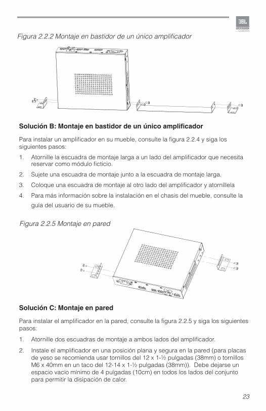
Solución B: Montaje en bastidor de un único amplificador
Para instalar un amplificador en su mueble, consulte la figura 2.2.4 y siga los siguientes pasos:
1. Atornille la escuadra de montaje larga a un lado del amplificador que necesita reservar como módulo ficticio.
2. Sujete una escuadra de montaje junto a la escuadra de montaje larga.
3. Coloque una escuadra de montaje al otro lado del amplificador y atorníllela
4. Para más información sobre la instalación en el chasis del mueble, consulte la
guía del usuario de su mueble.
Solución C: Montaje en pared
Para instalar el amplificador en la pared, consulte la figura 2.2.5 y siga los siguientes pasos:
1. Atornille dos escuadras de montaje a ambos lados del amplificador.
2. Instale el amplificador en una posición plana y segura en la pared (para placas de yeso se recomienda usar tornillos del 12 x 1-½ pulgadas (38mm) o tornillos M6 x 40mm en un taco del 12-14 x 1-½ pulgadas (38mm)). Debe dejarse un espacio vacío mínimo de 4 pulgadas (10cm) en todos los lados del conjunto para permitir la disipación de calor.
Figura 2.2.2 Montaje en bastidor de un único amplificador
Figura 2.2.5 Montaje en pared
24
2.3 Garantice una ventilación adecuada
Cuando use un bastidor, coloque las unidades directamente una encima de otra NO bloquee las ventilaciones laterales. La parte posterior del bastidor debería estar abierta.
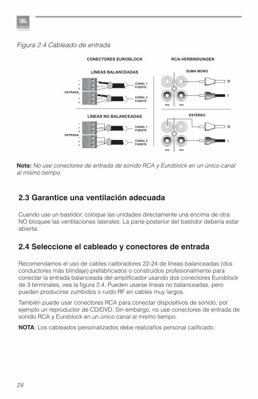
2.4 Seleccione el cableado y conectores de entrada
Recomendamos el uso de cables calibradores 22-24 de líneas balanceadas (dos conductores más blindaje) prefabricados o construidos profesionalmente para conectar la entrada balanceada del amplificador usando dos conectores Euroblock de 3 terminales, vea la figura 2.4. Pueden usarse líneas no balanceadas, pero pueden producirse zumbidos o ruido RF en cables muy largos.
También puede usar conectores RCA para conectar dispositivos de sonido, por ejemplo un reproductor de CD/DVD. Sin embargo, no use conectores de entrada de sonido RCA y Euroblock en un único canal al mismo tiempo.
NOTA: Los cableados personalizados debe realizarlos personal calificado.
CONECTORES EUROBLOCK
LÍNEAS BALANCEADAS SUMA MONO
D
I
D
I
ESTÉREOLÍNEAS NO BALANCEADAS
RCA-VERBINDUNGEN
ENTRADA
ENTRADA
CANAL 1FUENTE
FUENTE
FUENTE
FUENTE
CANAL 2
CANAL 1
CANAL 2
Figura 2.4 Cableado de entrada
Nota: No use conectores de entrada de sonido RCA y Euroblock en un único canal al mismo tiempo.
25
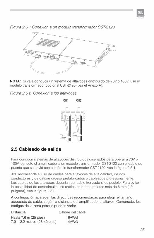
2.5 Cableado de salida
Para conducir sistemas de altavoces distribuidos diseñados para operar a 70V o 100V, conecte el amplificador a un módulo transformador CST-2120 con el cable de puente que se envió con el módulo transformador CST-2120, vea la figura 2.5.1.
JBL recomienda el uso de cables para altavoces de alta calidad, de dos conductores y de calibre grueso prefabricados o cableados profesionalmente. Los cables de los altavoces deberían ser cable trenzado si es posible. Para evitar la posibilidad de cortocircuito, los cables no deben pelarse más de 6 mm (1/4 pulgada), vea la figura 2.5.2.
A continuación aparecen las directrices recomendadas para elegir el tamaño adecuado de cable, según la distancia del amplificador al altavoz. Compruebe los códigos de la zona porque pueden variar.
Distancia Calibre del cableHasta 7,6 m (25 pies) 16AWG7,9 -12,2 metros (26-40 pies) 14AWG
Figura 2.5.1 Conexión a un módulo transformador CST-2120
NOTA: Si va a conducir un sistema de altavoces distribuido de 70V o 100V, use el módulo transformador opcional CST-2120 (vea el Anexo A).
TOSpeaker
TOSpeaker
Figura 2.5.2 Conexión a los altavoces
26
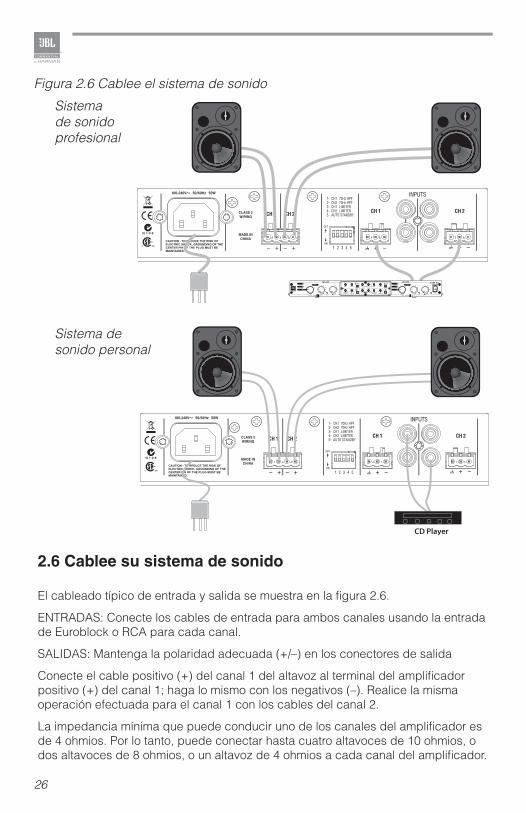
2.6 Cablee su sistema de sonido
El cableado típico de entrada y salida se muestra en la figura 2.6.
ENTRADAS: Conecte los cables de entrada para ambos canales usando la entrada de Euroblock o RCA para cada canal.
SALIDAS: Mantenga la polaridad adecuada (+/–) en los conectores de salida
Conecte el cable positivo (+) del canal 1 del altavoz al terminal del amplificador positivo (+) del canal 1; haga lo mismo con los negativos (–). Realice la misma operación efectuada para el canal 1 con los cables del canal 2.
La impedancia mínima que puede conducir uno de los canales del amplificador es de 4 ohmios. Por lo tanto, puede conectar hasta cuatro altavoces de 10 ohmios, o dos altavoces de 8 ohmios, o un altavoz de 4 ohmios a cada canal del amplificador.
Figura 2.6 Cablee el sistema de sonido
Sistema de sonido profesional
Sistema de sonido personal
27
2.7 Conecte al suministro eléctrico
Conecte su amplificador a la fuente de suministro eléctrico (toma de corriente) con el cable de CA provisto. Primero, conecte el extremo IEC del cable al conector IEC del amplificador; luego, conecte el otro extremo del cable a la toma de corriente.
ADVERTENCIA: El tercer contacto de este conector (tierra) es una característica de seguridad importante. No intente deshabilitar esta conexión a tierra usando un adaptador ni ningún otro método.
Los amplificadores no crean energía. La tensión y corriente del suministro eléctrico deben ser suficientes para proporcionar la potencia esperada. Debe operar su amplificador a partir de una fuente de suministro eléctrico de CA con no más de una variación del 10% por encima o por debajo del voltaje de línea especificado y dentro de la gama de frecuencia especificada indicada en la parte posterior del amplificador. Si no está seguro de la tensión de salida de su suministro eléctrico, consúltelo con un electricista.
2.8 Proteja sus altavoces
Es recomendable evitar recortar la señal del amplificador. No sólo el recorte suena mal, sino que puede dañar los conductores de frecuencia alta. El limitador de recorte incorporada evita los recortes.
También es recomendable evitar enviar señales subsónicas fuertes al amplificador. Las señales de frecuencia baja y nivel alto de los soplidos o los micrófonos caídos pueden estropear los conductores. Puede activar los filtros de paso-alto, y así evitará el envío de señales subsónicas por debajo de 70 Hz al amplificador. El uso del filtro de paso-alto es necesario cuando se usa el módulo transformador CST-2120 para conducir un sistema de altavoces distribuido de 70V o 100V a fin de evitar las distorsiones debidas a la saturación del transformador.
2.9 Procedimiento de puesta en marcha
Utilice el siguiente procedimiento cuando encienda por primera vez el amplificador:1. Baje el nivel de su fuente de sonido.2. Baje los controles de nivel del amplificador.3. Encienda el amplificador. Deberá encenderse el indicador de encendido.4. Suba el nivel de la fuente de sonido hasta llegar a un nivel óptimo.5. Suba los controles del nivel del amplificador hasta el volumen o nivel de
potencia deseado. Si necesita realizar algún cambio en el cableado o instalación, no olvide desconectar el cable de alimentación primero.
28
3.0 Funcionamiento
3.1 Precauciones
Su amplificador está protegido contra fallos internos y externos, pero debe tomar las siguientes precauciones para un funcionamiento óptimo y seguro:
1. Antes del uso, su amplificador debe primero ser configurado para una operación adecuada, incluyendo las conexiones de entrada y salida. Un cableado inadecuado puede provocar graves dificultades de operación.Para más información sobre el cableado y la configuración, consulte la sección Configuración del presente manual.
2. Tenga cuidado al hacer conexiones, al seleccionar fuentes de señal y al controlar el nivel de salida.
3. No una el cable de tierra de un cable de salida con la tierra de señal de entrada. Esto puede formar un circuito de tierra y causar oscilaciones
4. ADVERTENCIA: Nunca conecte la salida a un suministro eléctrico, batería o toma de corriente. Se puede producir una descarga eléctrica.
5. Intervenir los circuitos o realizar cambios no autorizados en los mismos puede ser peligroso e invalida todas las especificaciones del fabricantes.
6. No opere el amplificador con los LED de saturación (Clip) rojos parpadeando constantemente.
7. No sobreopere la mezcladora, lo cual causará el envío de señales distorsionadas al amplificador. Tales señales serán reproducidas con extrema precisión, y resultarán en daño a los altavoces.
8. No opere el amplificador con una impedancia de carga menor a la indicada. Debido a la protección de salida del amplificador, dicha configuración puede resultar en saturación prematura y daño al altavoz.
9. Use el amplificador en un entorno bien ventilado y no lo use en condiciones de temperatura ambiente superiores a 40ºC. En caso de no hacerlo, se producirá una desconexión automática del suministro eléctrico, y se activará la función de protección automática contra el sobrecalentamiento. El indicador de encendido se apagará y no saldrá ninguna señal de audio del amplificador. En tal caso, baje el volumen al mínimo, y el amplificador volverá a funcionar. Cuando el amplificador vuelva a la temperatura normal, puede subir el volumen hasta el nivel requerido.
10. Si la tensión de línea del amplificador es demasiado baja, se activará la función de protección de tensión baja. Se apagará el indicador de encendido.
ADVERTENCIA: JBL no es responsable por el daño que resulte de forzar otros componentes del sistema.
29
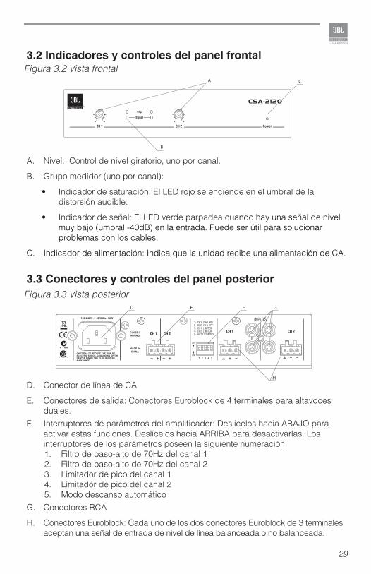
3.2 Indicadores y controles del panel frontal
A. Nivel: Control de nivel giratorio, uno por canal.
B. Grupo medidor (uno por canal):
• Indicador de saturación: El LED rojo se enciende en el umbral de la distorsión audible.
• Indicador de señal: El LED verde parpadea cuando hay una señal de nivel muy bajo (umbral -40dB) en la entrada. Puede ser útil para solucionar problemas con los cables.
C. Indicador de alimentación: Indica que la unidad recibe una alimentación de CA.
3.3 Conectores y controles del panel posterior
D. Conector de línea de CA
E. Conectores de salida: Conectores Euroblock de 4 terminales para altavoces duales.
F. Interruptores de parámetros del amplificador: Deslícelos hacia ABAJO para activar estas funciones. Deslícelos hacia ARRIBA para desactivarlas. Los interruptores de los parámetros poseen la siguiente numeración:1. Filtro de paso-alto de 70Hz del canal 12. Filtro de paso-alto de 70Hz del canal 23. Limitador de pico del canal 14. Limitador de pico del canal 25. Modo descanso automático
G. Conectores RCA
H. Conectores Euroblock: Cada uno de los dos conectores Euroblock de 3 terminales aceptan una señal de entrada de nivel de línea balanceada o no balanceada.
A C
B
D E F G
H
Figura 3.3 Vista posterior
Figura 3.2 Vista frontal
30
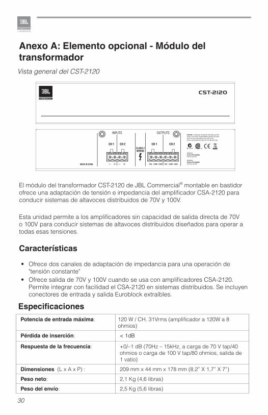
Anexo A: Elemento opcional - Módulo del transformador
El módulo del transformador CST-2120 de JBL Commercial® montable en bastidor ofrece una adaptación de tensión e impedancia del amplificador CSA-2120 para conducir sistemas de altavoces distribuidos de 70V y 100V.
Esta unidad permite a los amplificadores sin capacidad de salida directa de 70V o 100V para conducir sistemas de altavoces distribuidos diseñados para operar a todas esas tensiones.
Características
• Ofrece dos canales de adaptación de impedancia para una operación de "tensión constante"
• Ofrece salida de 70V y 100V cuando se usa con amplificadores CSA-2120. Permite integrar con facilidad el CSA-2120 en sistemas distribuidos. Se incluyen conectores de entrada y salida Euroblock extraíbles.
Vista general del CST-2120
Potencia de entrada máxima: 120 W / CH. 31Vrms (amplificador a 120W a 8 ohmios)
Pérdida de inserción: < 1dB
Respuesta de la frecuencia: +0/–1 dB (70Hz – 15kHz, a carga de 70 V tap/40 ohmios o carga de 100 V tap/80 ohmios, salida de 1 vatio)
Dimensiones (L x A x P) : 209 mm x 44 mm x 178 mm (8,2” X 1,7” X 7”)
Peso neto: 2,1 Kg (4,6 libras)
Peso del envío: 2,5 Kg (5,6 libras)
Especificaciones
31
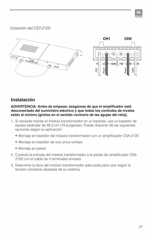
InstalaciónADVERTENCIA: Antes de empezar, asegúrese de que el amplificador está desconectado del suministro eléctrico y que todos los controles de niveles están al mínimo (gírelos en el sentido contrario de las agujas del reloj).
1. Si necesita montar el módulo transformador en un bastidor, use un bastidor de equipo estándar de 48,3 cm (19 pulgadas). Puede disponer de las siguientes opciones según su aplicación:
• Montaje en bastidor del módulo transformador con un amplificador CSA-2120
• Montaje en bastidor de una única unidad
• Montaje en pared
2. Conecte la entrada del módulo transformador a la salida del amplificador CSA-2120 con el cable de 4 terminales enviado.
3. Determine la llave del módulo transformador adecuada para usar según la tensión constante deseada de su sistema.
Conexión del CST-2120
Negro
Negro
32
Potencia de salida(dos canales a una potencia de 1 kHz, THD+N<0.5%):
4 ohmios 120 W 8 ohmios 120 W
Respuesta de la frecuencia(1 vatio en 4 o 8 ohmios):
+1/-1 dB
Impedancia de carga: Clasificada para 4 u 8 ohmios
Sensibilidad (carga de 8 ohmios): 1,4 Vrms
Relación señal/ruido (inferior a la nominal de 8 ohmios a 1 kHz, ponderada A):
>100 dB
Diafonía (Potencia por debajo de la nominal):
>70dB de 20Hz a 1kHz; >50dB a 20kHz
Impedancia de entrada (nominal): Balanceada: 20 k ohmiosNo balanceada: 10 k ohmios
Frecuencia y tensión de la línea de CAConfiguraciones disponibles:
100-240 V, 50/60 Hz
Señal de entrada máxima: +20 dBu típico
Temperatura de funcionamiento: 0° C a 40° C a una humedad relativa del 95%(sin condensación)
Modo descanso automático: Tiempo de recuperación del modo de descanso automático: <1msUmbral de recuperación del modo de descanso automático: – 60dBu
Dimensiones (L x A x P) : 209 mm x 44 mm x 178 mm (8,2” x 1,7” x 7”)
Peso neto: 1 kg (2,1 libras)
Peso del envío: 1,7 kg (3,8 libras)
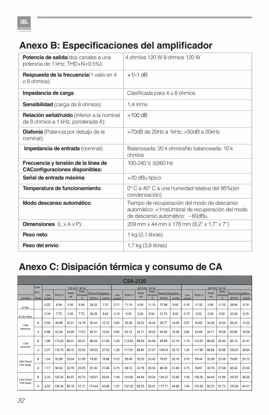
Anexo C: Disipación térmica y consumo de CA
Anexo B: Especificaciones del amplificador

33
Anexo D: Información de contacto
Para más información, rogamos consulte con la atención al cliente de JBL Professional, con su distribuidor o con el minorista.
Página web:www.jblcommercialproducts.com
Contactos profesionales fuera de EEUU:Contacte con el distribuidor JBL Professional de su zona. En nuestra página web de EEUU aparece una lista completa de distribuidores internacionales profesionales de JBL: www.jblpro.com

34

35

Part Number: 5009280 Issue: 01/12
JBL Commercial8760 South Sandy Pkwy. Sandy, UT 84070 USA(801) 566-8800