cs1104 help session vi miscellaneous topics colin tan, [email protected] s15-04-15
TRANSCRIPT


Topic 1Instruction Encoding
• Computers can only understand numbers!• Computers cannot make sense out of instructions like:
– lw $1, 0($3)
– add $5, $2, $1
• This form of representation is called assembly language, and is meant to simplify the programmer’s life.– Before the machine can understand this code, it must be
assembled into machine code, which is the numerical equivalent of the assembly instruction

Topic 1Instruction Encoding
• The design of the numeric representation for these assembly instructions is called instruction encoding, or simply instruction coding.
• Instruction encoding forms a very important part of instruction set architecture (ISA) design– Encoding designs can affect the type of operands an
instruction can accept, and the range of operands• If more bits are designated as operand bits, then we can
support more (or bigger) operands.

Topic 1Instruction Encoding
• A typical instruction looks like this:
OpCode Operand 1 Operand 2 .... Operand n
• The opcode portion of the instruction tells us what operation to perform (e.g. add, subtract, etc.)
• The operandx portions either provide the data directly (Immediate addressing), tells us which registers (register addressing), or which addresses to fetch the data from.
Topic 1Instruction Encoding
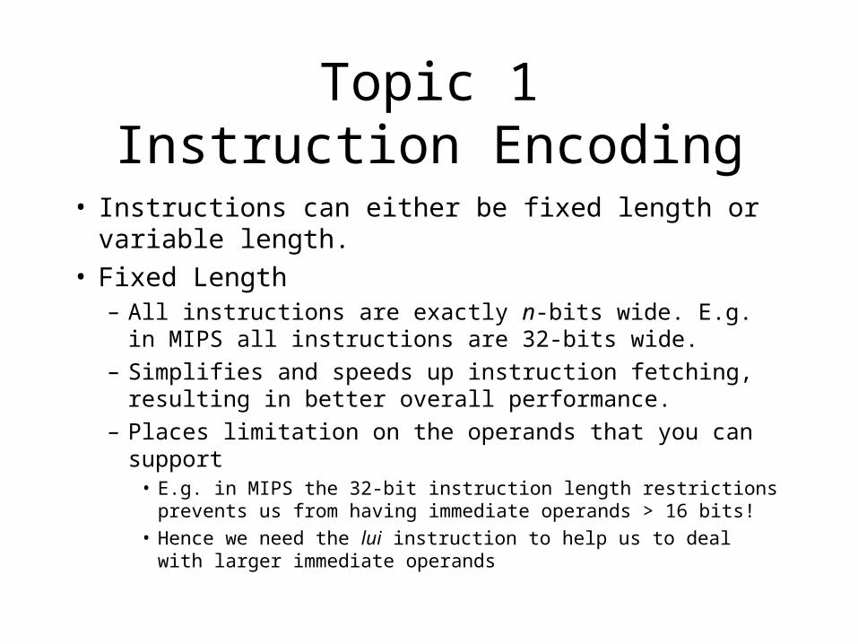
• Instructions can either be fixed length or variable length.
• Fixed Length– All instructions are exactly n-bits wide. E.g. in MIPS all
instructions are 32-bits wide.– Simplifies and speeds up instruction fetching, resulting in
better overall performance.– Places limitation on the operands that you can support
• E.g. in MIPS the 32-bit instruction length restrictions prevents us from having immediate operands > 16 bits!
• Hence we need the lui instruction to help us to deal with larger immediate operands

Topic 1Instruction Encoding
• Variable Length– The instruction can be anywhere between x and y bits in
length.• E.g. Instructions can be anywhere between 8 bits to 256 bits.
– This results in great flexibility in placing operands• Can have instructions with dozens of operands! No length
restriction!
• Can have very big operands e.g. 128 bit immediate values.
– This also complicates and slows down instruction fetching.• No way to predict in advance how many bits of instruction to
fetch. Must fetch opcode portion first and then decide.

Topic 1Instruction Encoding
• Instructions are divided into different classes. Some examples include:– Arithmetic Instructions: add, sub, mul, div etc.
– Bitwise Instructions: asl (left shift), asr (right shift), or, and, etc.
– Branch Instructions: beq, bne, etc.
– Test and set instructions: slt, slti
– Floating Point Instructions: fadd, fsub, fmul, fdiv, etc.

Topic 1Instruction Encoding
• Example: Suppose the opcode for the add instruction is 010102, and the opcode for registers $1 and $2 are 00012 and 00102 respectively, what would be the machine code translation of add $1, $2, $2?
• Placing the opcode and operand values in their respective places, we get:
01010 0001 0010 0010

Topic 1Instruction Encoding
• This is what is actually read and understood by the CPU when it executes your program.– In the memory this instruction is stored as a number. Here it is 01010 0001
0010 00102, or A12216, or 4125010.
– This number is picked up by the CPU, interpreted and executed.
• Note that the CPU has no way of differentiating between data and instructions!– To the CPU, the number 4125010 is either instruction or data.
– YOU are responsible for telling the CPU which is which!– If this is not done properly, the CPU could end up trying to execute data
instead of instructions• Unpredictable results
• Cause of those irritating “Illegal Instruction” errors in Windows.

Topic 1Instruction Encoding
• Tutorial 3, Question A-4A certain machine has 12 bit instructions and 4-bit addresses. Some
instructions have 2 addresses, some have one address, and the rest have zero. ALL these three types of instructions exist in the machine (i.e. there is at least one instruction from each type).
a) What is the maximum number of instructions with 1 address?
b) What is the maximum number of instructions with zero address?
c) What is the minimum total number of instructions, assuming that the encoding space of the instruction word is completely utilized?
d) What is the maximum total number of instructions, assuming that the encoding space of the instruction word is completely utilized?

Solution
• I: Class of instructions with 2 addressesOpCode1
4 bitsAdd14 bits
Add24 bits
• J: Class of instructions with 1 addressesOpCode1
4 bitsOpCode2
4 bitsAdd24 bits
• K: Class of instructions with 1 addressesOpCode1
4 bitsOpCode2
4 bitsOpCode3
4 bits

Solution
• Key idea: Opcodes differentiate between instruction classes.
• The instruction decoder looks at the opcode1 field, and decides if the next field is opcode2 or memory address.
• If it decides that the next field is opcode2, it will look at opcode2 and decide if the field after that is opcode3 or memory address.
• Once it has made the decisions, it will treat each field accordingly– Opcode fields are sent to the instruction decoder
– Memory address fields are sent to the MEM stage.

Solution
• Part a) Maximum number of instructions with one address:
To get this, we must minimize the number of class I and class K instructions. The minimum for each is one. We start with the class I instruction, and assign 0000 to opcode 1. When the CPU sees 0000 in opcode1, it knows that the next 2 fields are memory addresses, and looks no further.
OpCode10000
Add14 bits
Add24 bits

Solution
Now we minimize class K. We set opcode1 to be 0001 (cannot be 0000 as this indicates class I instructions), we set opcode2 to be 0000 (to indicate that there is an opcode3 field), and we set opcode3 to be 0000 (the one single class K opcode!)
OpCode10001
OpCode20000
Add20000

Solution
Now comes the hard part: We find the maximum number of class J instructions.
If opcode1 is between 0010 and 1111, we have no problem, as these patterns have never occurred before, so opcode2 can be any value between 0000 and 1111.
But if opcode1 is 0001, then opcode2 cannot be 0000 as this indicates a class K instruction. So opcode2 must be between 0001 and 1111. This gives us 2 options:

Solution
Option I: Opcode1 is 0010 to 1111 (14 combinations), opcode2 is 0000 to 1111 (16 combinations). Total number of combinations is 14 x 16
OpCode10010-1111
OpCode20000-1111
Add24 bits
OpCode10001
OpCode20001-1111
Add24 bits
Option II: Opcode1 is 0001 (1 combination), opcode2 is 0001 to 1111 (15 combinations). Total number of combinations is 1 x 15

Solutions
The total number of combinations is therefore 14x16 + 1 x 15 = 239. Therefore we can have a maximum of 239 class J instructions
• Part B: Maximum number of class K instructions?– Tackled in identical manner to Part A, but we minimize
classes I and J instead.
– All logic and rational exactly the same.
– Final answer is 3824 instructions.
Solutions
• Part C: To get the minimum number of instructions that can be encoded, assuming the instruction word space is fully utilized (i.e. there are no unused bit combinations), we start maximizing from the smallest class.– Rational is that maximizing the smallest class will give
us a tiny number of instructions, yet take away bit-combination possibilities from the larger classes.

Solutions
Maximize class I first: Opcode1 can take any value between 0000 and 1111, but at least 1 bit combination must be set aside to indicate class J and K instructions. We set aside 0000. So class I Opcode1 values can be between 0001 and 1111, giving us a maximum of 15 instructions.
Maximize class J now: Opcode1 can only take the value of 0000 (any other value belongs to class I), and opcode2 can take any value between 0000 and 1111, but again we must set aside 1 value to indicate class K instructions. We set aside 0000 for opcode2 to indicate class K instructions. Thus opcode2 for class J instructions can take the values of 0001 to 1111, giving us 15 instructions.

Solutions
Maximize class K instructions: For class K instructions, opcode1 and opcode2 must be 0000 0000 (any other values would indicate class I or class J instructions).
Opcode3 is free to take any value between 0000 and 1111, giving us 16 class K instructions.
Hence the minimum total number of instructions, assuming encoding space is fully utilized, is 15+15+16 = 46 instructions.

Solutions• Part D: To get the maximum number of
instructions that can be encoded, assuming the instruction word space is fully utilized (i.e. there are no unused bit combinations), we start maximizing from the largestclass.
The largest class is class K, and the maximum number of instructions in class K is 3824 (see part b).
To derive this figure, we assumed that there are minimal instructions in class I and J, i.e. class I and J consist of 1 instruction each.
Thus total number of instructions is 3284 + 1 + 1 = 3826 instructions.

Solutions
• For a more complete treatment of this tutorial, see my website at:– http://www.comp.nus.edu.sg/~ctank

Topic 2Instruction Execution
• We’ve seen how instructions can be encoded as numbers that the CPU can understand.
• But how precisely does the CPU execute the commands?
• Usually instruction execution is divided into a number of phases (each phase typically takes 1 clock cycle to complete)– Fetch phase
– Decode phase
– Execute phase
– Memory phase
– Writeback phase

Topic 2Instruction Execution
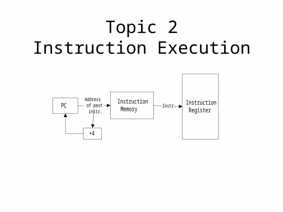
• Fetch Phase– The program counter PC gives the address of the next
instruction to be executed.
– The processor uses this address to access the instruction cache, and fetches the next instruction (e.g. 01010 0001 0010 00102 in our previous example).
– The instruction is placed into a holding register, normally called the Instruction Register.
– In the MIPS, the PC is then incremented by 4 to make it point to the next instruction.
Topic 2Instruction Execution
InstructionMemoryPC
Addressof nextinstr.
InstructionRegister
Instr.
+4
Topic 2Instruction Execution
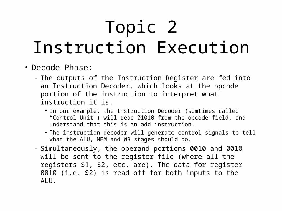
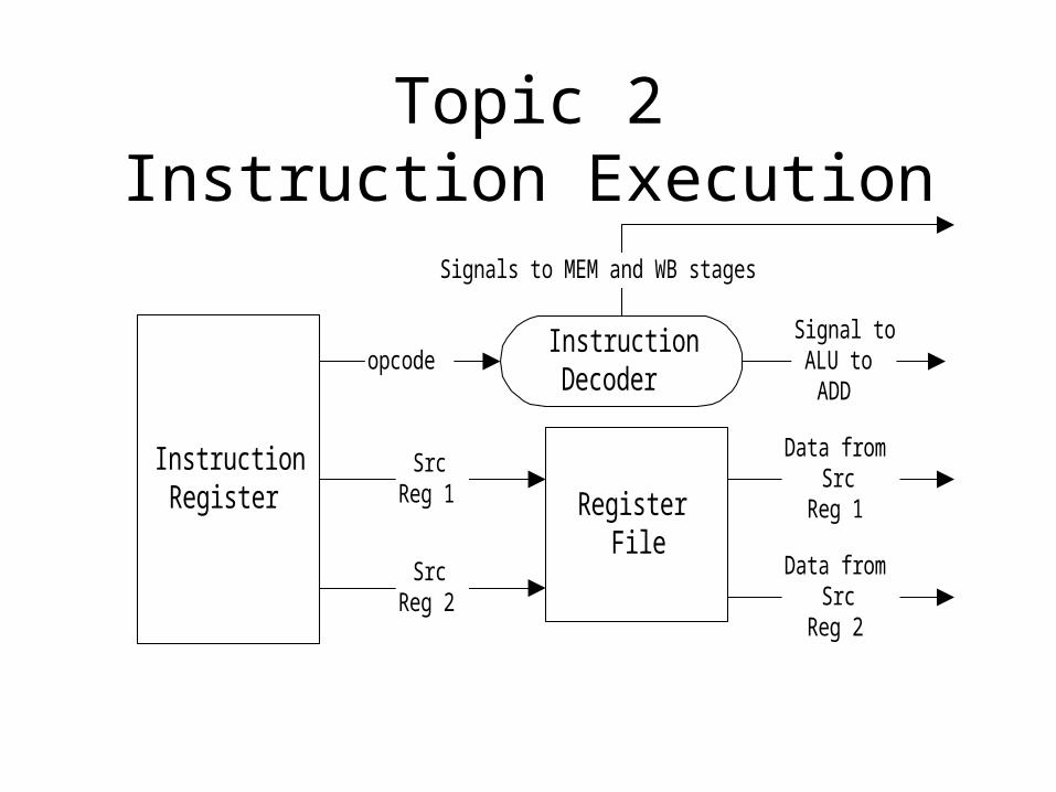
• Decode Phase:– The outputs of the Instruction Register are fed into an Instruction
Decoder, which looks at the opcode portion of the instruction to interpret what instruction it is.
• In our example, the Instruction Decoder (somtimes called “Control Unit”) will read 01010 from the opcode field, and understand that this is an add instruction.
• The instruction decoder will generate control signals to tell what the ALU, MEM and WB stages should do.
– Simultaneously, the operand portions 0010 and 0010 will be sent to the register file (where all the registers $1, $2, etc. are). The data for register 0010 (i.e. $2) is read off for both inputs to the ALU.
Topic 2Instruction Execution
InstructionRegister
InstructionDecoder
opcode
RegisterFile
SrcReg 1
SrcReg 2
Data fromSrc
Reg 1
Data fromSrc
Reg 2
Signal toALU to
ADD
Signals to MEM and WB stages

Topic 2Instruction Execution
• Execute Phase– Here the actual instruction is actually carried out.
– For our example, it will take the data from the source registers, add them together, and produce an output.
– For lw and sw instructions, this stage actually computes the memory addresses to load from (lw) or write to (sw).

Topic 2 Instruction Execution
ALU
Data fromSrc
Reg 1
Data fromSrc
Reg 2
ALU Result
ADD/SUB etc. commandfrom Instruction
Decoder
Topic 2Instruction Execution
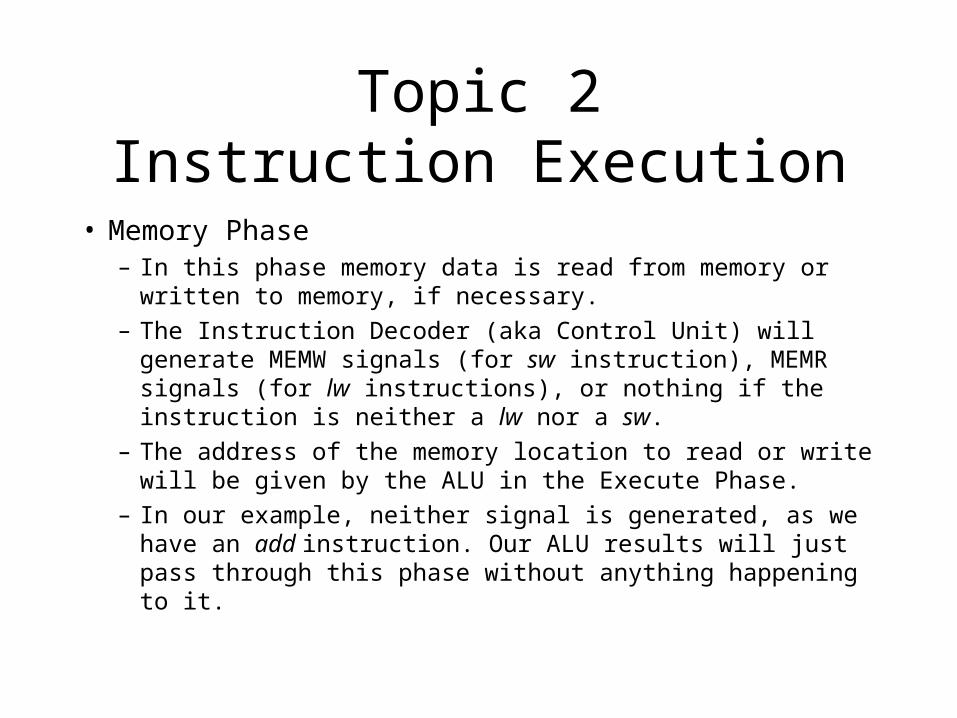
• Memory Phase– In this phase memory data is read from memory or written to
memory, if necessary.
– The Instruction Decoder (aka Control Unit) will generate MEMW signals (for sw instruction), MEMR signals (for lw instructions), or nothing if the instruction is neither a lw nor a sw.
– The address of the memory location to read or write will be given by the ALU in the Execute Phase.
– In our example, neither signal is generated, as we have an add instruction. Our ALU results will just pass through this phase without anything happening to it.

Topic 2Instruction Execution
MainMemory or
Data Cache
Address fromALU
MEMW or MEMRsignals from
Decoder
Data to bewritten
(sw only)
Data read(lw only)

Topic 2Instruction Execution
• Writeback Phase– In this phase, the results of the computation (or
memory data read, in the case of lw) is written back to the destination register.
– In our example, our result of $2 + $2 is to be written back to $1.
– The Instruction Decoder had asserted the REGW signal in the decode phase, while the destination register portion of our instruction (the 0001 in our example, indicating $1) specifies which register to write to.
– Note that the REGW signal will not be activated for sw instructions, since sw does not require data to be written to registers.
Topic 2Instruction Execution
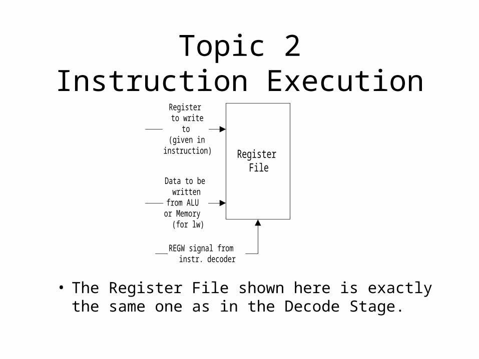
RegisterFile
Data to bewritten
from ALUor Memory
(for lw)
Registerto write
to(given in
instruction)
REGW signal frominstr. decoder
• The Register File shown here is exactly the same one as in the Decode Stage.

Topic 3Floating Point Numbers
• Assuming a 32-bit data word size, a fixed point number system assumes that x bits are reserved for the integer portion of a number, while 32-x bits are reserved for the fraction.
• This limits the range of number representation.– Limited number of bits in integer => limits size of integer (e.g.
16-bit integer portion allows us to represent integers between -32768 and 32767.
– Likewise with fraction portion.
• Floating Point number systems remove this limitation.

Topic 3Floating Point Numbers
• In the floating point number system, the binary point separating the integer and fraction portions is allowed to “float” along the number, by adjusting the exponent value:– e.g. 1 x 10^0 = 0.1 x 10^1 = 0.01 x 10^2 = 0.001 x
10^3 ad infinitum.
• This gives us very large ranges for our numbers.
Sign Significand Exponent
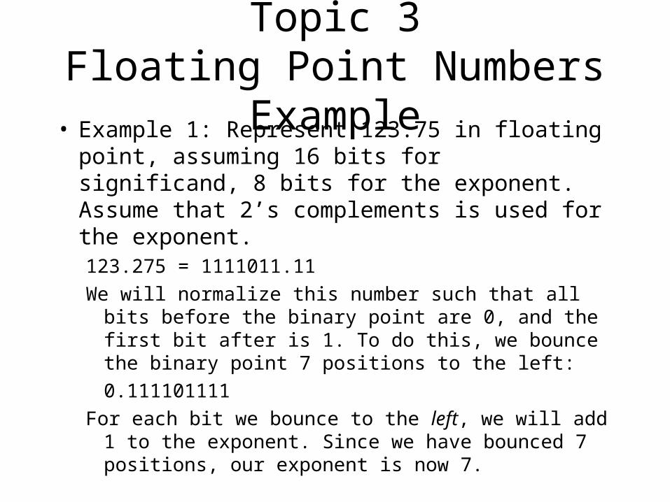
Topic 3Floating Point Numbers Example• Example 1: Represent 123.75 in floating point,
assuming 16 bits for significand, 8 bits for the exponent. Assume that 2’s complements is used for the exponent.123.275 = 1111011.11
We will normalize this number such that all bits before the binary point are 0, and the first bit after is 1. To do this, we bounce the binary point 7 positions to the left:
0.111101111
For each bit we bounce to the left, we will add 1 to the exponent. Since we have bounced 7 positions, our exponent is now 7.
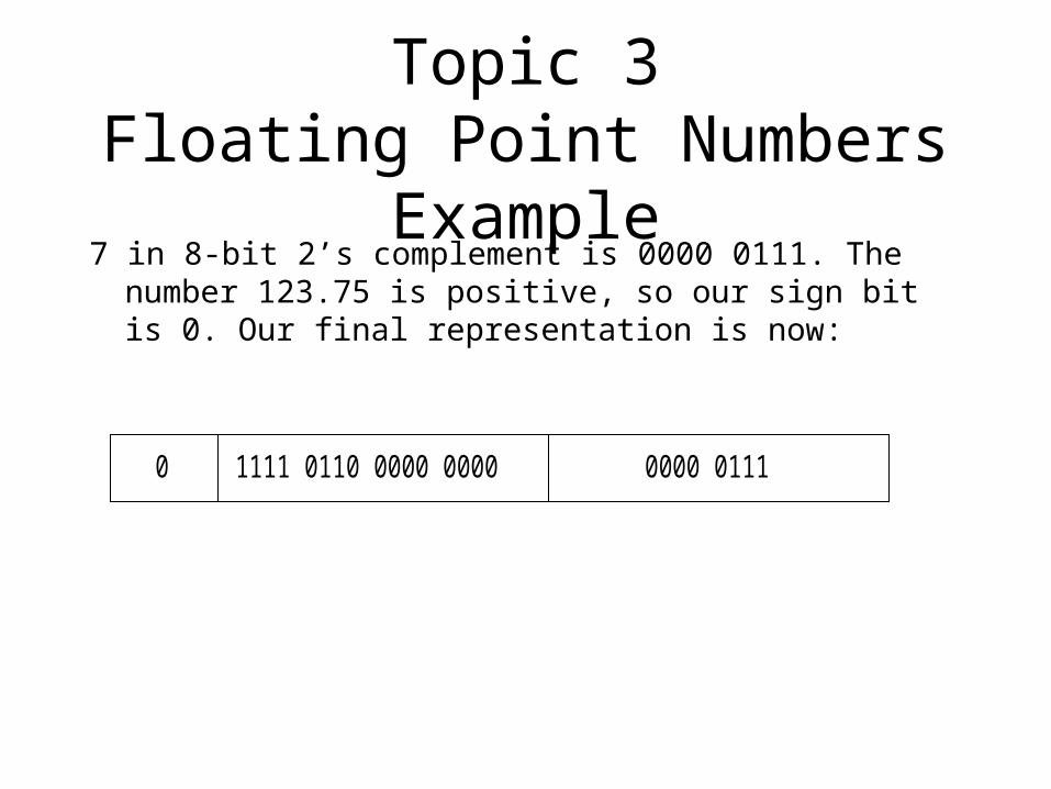
Topic 3Floating Point Numbers Example7 in 8-bit 2’s complement is 0000 0111. The number 123.75
is positive, so our sign bit is 0. Our final representation is now:
0 1111 0110 0000 0000 0000 0111

Topic 3Floating Point Numbers
• Because of normalization, the bit immediately to the right of the binary point is always 1.
• We can always safely assume that this bit is 1, and there is no need to explicitly represent it. In our example above, using this technique we effectively have 17 significand bits: this 1 hidden bit, and the 16 bits that we can see. The hidden bit is not shown (it is hidden!), so under this new scheme our previous answer becomes:
0 1110 1100 0000 0000 0000 0111

Topic 3Floating Point Numbers
• Example 2: What is the floating point representation of 0.2421875? Assume that the exponent is 8 bit 2’s complement, the significand is 16+1 bits (i.e. 16 bits that we can see, and 1 hidden bit).
0.1875 = 0.00111112
To normalize, shift the binary point 2 places to the right. We get 0.11111. For each position we shift the binary point to the right, we subtract 1 from the exponent. So our exponent is -2.

Topic 3Floating Point Numbers
Our significand is thus 11111 0000 0000 0000, where the italicised 1 is the hidden bit (note that we have 17 significand bits!).
Our exponent is -2, or 1111 1110 in 2’s complement. Our representation is thus:
0 1111 0000 0000 0000 1111 1110
Note that the first 1 has disappeared from the representation. The hardware assumes that it is there, and we don’t represent it in memory.

Topic 3Floating Point Numbers
• Example: Given a floating point value 1 1100 0111 0000 0000 0010 0111, and using the floating point format of our previous 2 examples, find the decimal equivalent.
1 1100 0111 0000 0000 0010 0111

Topic 3Floating Point Numbers
With our hidden bit, the actual significand is 0.11100 0111 0000 0000
This is 1/2+1/4+1/8+1/16+1/256+1/512+1/1024 = 0.9443359375
Exponent (assuming 2’s complement) is 0010 0111 or 39. Our value is thus 0.9443359375 x 2^39 = 5.192 x 10^11
Since the sign bit is 1, the final value is -5.192 x 10^11

Topic 3Floating Point Numbers
• Using 2’s complement (or even 1’s complement or sign+magnitude) exponents leads to a complication:– Assuming 4 bit significand, 8 bit 2’s complement
exponent, then 0.111 x 2^3 is:
0 1100 0000 0011
– 0.111 x 2^-3 is:
0 1100 1111 1101

Topic 3Floating Point Numbers
• If we compared the bit patterns for 0.111x2^3 and 0.111 x 2^-3, we will be comparing 0 1100 0000 0011 vs. 0 1100 1111 1101respectively
• In binary form, it looks like 0.111x2^-3 is bigger than 0.111 x 2^3!!– This complicates matters when we want to use integer
compare operations (fast, cheap to use) to compare floating point numbers!
• We introduce the bias concept to fix this problem.

Topic 3Floating Point Numbers
• Bias: For an n bit exponent, we add a bias of 2n-1 to the exponent to make it into a positive number:– Old range for 8-bit 2’s complement exponent is -128 to
127.– If we add a bias of 28-1 (i.e. a bias of 128) to the
exponent, we can remap the exponent to the range of 0 to 255.
• For our example, the exponents for 0.11x2^3 will be 128+3 = 131, while 0.11x2^-3 will have an exponent of -3+128 = 125.

Topic 3Floating Point Numbers
• This gives us the following representations:• For 0.11 x 2^3:
0 1100 1000 0011
• For 0.11 x 2^-3:
0 1100 0111 1101
• Now it is obvious from the binary representation which number is bigger. Can now use integer comparisons to compare 2 floating point numbers!

Topic 3Floating Point Numbers
• Find the decimal value of 1 1100 0111 0000 0000 0010 0111 given that we have 1 sign bit, 16 significand bits, and 8 exponent bits in biased representation.
1 1100 0111 0000 0000 0010 0111
• The actual significand, including hidden bit, is 11100 0111 0000 0000 = 1/2+1/4+1/8+1/16+1/256+1/512+1/1024 = 0.9443359375
• The exponent here is 39. However we had added in 128 to get the biased representation, and now we must minus 128, giving us an actual exponent of -89.
Topic 3Floating Point Numbers
• Our value is thus 0.9443359375 x 2 ^ -89 or 1.717 x 10^-12.
• Since the sign bit is 1, this gives us a value of -1.717 x 10^-12.
Topic 3Floating Point Numbers
• Some problems:– Certain numbers cannot be represented accurately. For
example the decimal value 0.11 (not binary!).
– There is a compromise between number of significand bits and number of exponent bits, since word size of a computer is fixed:
• More significand bits => more accurate representations, smaller range
• More exponent bits => less accurate representations, larger range

Topic 3Floating Point Numbers
• For more information, please revise CS1103 Number Systems.