cs-cj series operation manual · section 1 presents an overview of the cs/cj-series analog i/o...
TRANSCRIPT
Cat. No. W368-E1-10
SYSMAC
Analog I/O Units
CS SeriesCS1W-PTS@@/PTW@@/PDC@@/PTR@@/PPS@@/PMV@@CJ SeriesCJ1W-PTS@@/PDC@@/PH41U
OPERATION MANUAL

CS Series CS1W-PTS@@/PTW@@/PDC@@/PTR@@/PPS@@/PMV@@CJ Series CJ1W-PTS@@/PDC@@/PH41U
Analog I/O UnitsOperation ManualRevised July 2008

iv

Notice:OMRON products are manufactured for use according to proper procedures by a qualified operatorand only for the purposes described in this manual.
The following conventions are used to indicate and classify precautions in this manual. Always heedthe information provided with them. Failure to heed precautions can result in injury to people or dam-age to property.
!DANGER Indicates an imminently hazardous situation which, if not avoided, will result in death orserious injury. Additionally, there may be severe property damage.
!WARNING Indicates a potentially hazardous situation which, if not avoided, could result in death orserious injury. Additionally, there may be severe property damage.
!Caution Indicates a potentially hazardous situation which, if not avoided, may result in minor ormoderate injury, or property damage.
OMRON Product ReferencesAll OMRON products are capitalized in this manual. The word “Unit” is also capitalized when it refers toan OMRON product, regardless of whether or not it appears in the proper name of the product.
The abbreviation “Ch,” which appears in some displays and on some OMRON products, often means“word” and is abbreviated “Wd” in documentation in this sense.
The abbreviation “PLC” means Programmable Controller. “PC” is used, however, in some Program-ming Device displays to mean Programmable Controller.
Visual AidsThe following headings appear in the left column of the manual to help you locate different types ofinformation.
Note Indicates information of particular interest for efficient and convenient opera-tion of the product.
1,2,3... 1. Indicates lists of one sort or another, such as procedures, checklists, etc.
OMRON, 2000All rights reserved. No part of this publication may be reproduced, stored in a retrieval system, or transmitted, in any form, orby any means, mechanical, electronic, photocopying, recording, or otherwise, without the prior written permission ofOMRON.
No patent liability is assumed with respect to the use of the information contained herein. Moreover, because OMRON is con-stantly striving to improve its high-quality products, the information contained in this manual is subject to change withoutnotice. Every precaution has been taken in the preparation of this manual. Nevertheless, OMRON assumes no responsibilityfor errors or omissions. Neither is any liability assumed for damages resulting from the use of the information contained inthis publication.
v

vi

TABLE OF CONTENTS
PRECAUTIONS . . . . . . . . . . . . . . . . . . . . . . . . . . . . . . . . . . . . . xvii1 Intended Audience . . . . . . . . . . . . . . . . . . . . . . . . . . . . . . . . . . . . . . . . . . . . . . . . . . . . . . . . . . . xviii
2 General Precautions . . . . . . . . . . . . . . . . . . . . . . . . . . . . . . . . . . . . . . . . . . . . . . . . . . . . . . . . . . xviii
3 Safety Precautions. . . . . . . . . . . . . . . . . . . . . . . . . . . . . . . . . . . . . . . . . . . . . . . . . . . . . . . . . . . . xviii
4 Operating Environment Precautions . . . . . . . . . . . . . . . . . . . . . . . . . . . . . . . . . . . . . . . . . . . . . . xix
5 Application Precautions . . . . . . . . . . . . . . . . . . . . . . . . . . . . . . . . . . . . . . . . . . . . . . . . . . . . . . . xx
6 Conformance to EC Directives . . . . . . . . . . . . . . . . . . . . . . . . . . . . . . . . . . . . . . . . . . . . . . . . . . xxii
SECTION 1Overview and Features . . . . . . . . . . . . . . . . . . . . . . . . . . . . . . . 1
1-1 Overview of Analog I/O Units . . . . . . . . . . . . . . . . . . . . . . . . . . . . . . . . . . . . . . . . . . . . . . . . . . 2
1-2 Features and Functions . . . . . . . . . . . . . . . . . . . . . . . . . . . . . . . . . . . . . . . . . . . . . . . . . . . . . . . . 7
1-3 System Configuration . . . . . . . . . . . . . . . . . . . . . . . . . . . . . . . . . . . . . . . . . . . . . . . . . . . . . . . . . 24
1-4 Specifications and Installation . . . . . . . . . . . . . . . . . . . . . . . . . . . . . . . . . . . . . . . . . . . . . . . . . . 26
1-5 Operating Procedures . . . . . . . . . . . . . . . . . . . . . . . . . . . . . . . . . . . . . . . . . . . . . . . . . . . . . . . . . 55
1-6 Error Processing . . . . . . . . . . . . . . . . . . . . . . . . . . . . . . . . . . . . . . . . . . . . . . . . . . . . . . . . . . . . . 57
1-7 Specification Changes . . . . . . . . . . . . . . . . . . . . . . . . . . . . . . . . . . . . . . . . . . . . . . . . . . . . . . . . . 61
SECTION 2Individual Unit Descriptions for CS Series . . . . . . . . . . . . . . . 67
2-1 CS1W-PTS01-V1 Isolated-type Thermocouple Input Unit . . . . . . . . . . . . . . . . . . . . . . . . . . . . 68
2-2 CS1W-PTS11 Isolated-type Thermocouple Input Unit . . . . . . . . . . . . . . . . . . . . . . . . . . . . . . . 80
2-3 CS1W-PTS51 Isolated-type Thermocouple Input Unit . . . . . . . . . . . . . . . . . . . . . . . . . . . . . . . 97
2-4 CS1W-PTS55 Isolated-type Thermocouple Input Unit . . . . . . . . . . . . . . . . . . . . . . . . . . . . . . . 109
2-5 CS1W-PTS02 Isolated-type Resistance Thermometer Input Unit (Pt100 or JPt100). . . . . . . . . 121
2-6 CS1W-PTS03 Isolated-type Resistance Thermometer Input Unit (Ni508.4) . . . . . . . . . . . . . . . 132
2-7 CS1W-PTS12 Isolated-type Resistance Thermometer Input Unit (Pt100, JPt100, Pt50, Ni508.4) 142
2-8 CS1W-PTS52 Isolated-type Resistance Thermometer Input Unit (Pt100, JPt100) . . . . . . . . . . 157
2-9 CS1W-PTS56 Isolated-type Resistance Thermometer Input Unit (Pt100, JPt100) . . . . . . . . . . 167
2-10 CS1W-PTW01 2-Wire Transmitter Input Unit . . . . . . . . . . . . . . . . . . . . . . . . . . . . . . . . . . . . . . 177
2-11 CS1W-PDC01 Isolated-type Direct Current Input Unit . . . . . . . . . . . . . . . . . . . . . . . . . . . . . . . 189
2-12 CS1W-PDC11 Isolated-type Direct Current Input Unit . . . . . . . . . . . . . . . . . . . . . . . . . . . . . . . 200
2-13 CS1W-PDC55 Isolated-type Direct Current Input Unit . . . . . . . . . . . . . . . . . . . . . . . . . . . . . . . 218
2-14 CS1W-PTR01 Power Transducer Input Unit . . . . . . . . . . . . . . . . . . . . . . . . . . . . . . . . . . . . . . . 229
2-15 CS1W-PTR02 Analog Input Unit (100 mV). . . . . . . . . . . . . . . . . . . . . . . . . . . . . . . . . . . . . . . . 238
2-16 CS1W-PPS01 Isolated-type Pulse Input Unit . . . . . . . . . . . . . . . . . . . . . . . . . . . . . . . . . . . . . . . 247
2-17 CS1W-PMV01 Isolated-type Analog Output Unit . . . . . . . . . . . . . . . . . . . . . . . . . . . . . . . . . . . 258
2-18 CS1W-PMV02 Isolated-type Analog Output Unit . . . . . . . . . . . . . . . . . . . . . . . . . . . . . . . . . . . 267
vii

TABLE OF CONTENTS
SECTION 3Individual Unit Descriptions for CJ Series . . . . . . . . . . . . . . . 275
3-1 CJ1W-PTS51 Isolated-type Thermocouple Input Unit . . . . . . . . . . . . . . . . . . . . . . . . . . . . . . . . 276
3-2 CJ1W-PTS15 Isolated-type Thermocouple Input Unit . . . . . . . . . . . . . . . . . . . . . . . . . . . . . . . . 288
3-3 CJ1W-PTS52 Isolated-type Resistance Thermometer Input Unit (Pt100, JPt100). . . . . . . . . . . 302
3-4 CJ1W-PTS16 Isolated-type Resistance Thermometer Input Unit (Pt100, JPt100, Pt50, Ni508.4) 312
3-5 CJ1W-PDC15 Isolated-type Direct Current Input Unit . . . . . . . . . . . . . . . . . . . . . . . . . . . . . . . 324
3-6 CJ1W-PH41U Isolated-type Universal Input Unit . . . . . . . . . . . . . . . . . . . . . . . . . . . . . . . . . . . 338
AppendicesA Supplementary Explanation of Functions . . . . . . . . . . . . . . . . . . . . . . . . . . . . . . . . . . . . . . . . . 365
B Zero/Span Adjustment Example . . . . . . . . . . . . . . . . . . . . . . . . . . . . . . . . . . . . . . . . . . . . . . . . 375
Index . . . . . . . . . . . . . . . . . . . . . . . . . . . . . . . . . . . . . . . . . . . . . . 379
Revision History . . . . . . . . . . . . . . . . . . . . . . . . . . . . . . . . . . . . . 383
viii

About this Manual:
This manual describes the installation and operation of the CS/CJ-series Analog I/O Units andincludes the sections described below.
In this manual, “Analog I/O Units” is a product group name for the following groups of Units.
Please read this manual carefully and be sure you understand the information provided beforeattempting to install and operate the Analog I/O Units.
Precautions provides general precautions for using the CS/CJ-series Programmable Controllers(PLCs) and related devices.
Section 1 presents an overview of the CS/CJ-series Analog I/O Units, and outlines their features.
Section 2 describes each of the CS-series Analog I/O Units in detail.
Section 3 describes each of the CJ-series Analog I/O Units in detail.
Appendix A provides a supplementary explanation of Unit functions.
Appendix B provides an example of zero/span adjustment.
Name Model number
CS-series Isolated-type Thermocouple Input Unit CS1W-PTS01-V1
CS1W-PTS11
CS1W-PTS51
CS1W-PTS55
Isolated-type Resistance Thermometer Input Unit (Pt100 or JPt100) CS1W-PTS02
Isolated-type Resistance Thermometer Input Unit (Ni508.4) CS1W-PTS03
Isolated-type Resistance Thermometer Input Unit (Pt100, JPt100, Pt50, or Ni508.4)
CS1W-PTS12
Isolated-type Resistance Thermometer Input Unit (Pt100, JPt100) CS1W-PTS52
CS1W-PTS56
Isolated-type 2-Wire Transmitter Input Unit CS1W-PTW01
Isolated-type Direct Current Input Unit CS1W-PDC01
CS1W-PDC11
CS1W-PDC55
Power Transducer Input Unit CS1W-PTR01
Analog Input Unit CS1W-PTR02
Isolated-type Pulse Input Unit CS1W-PPS01
Isolated-type Analog Output Unit CS1W-PMV01/PMV02
CJ-series Isolated-type Thermocouple Input Unit CJ1W-PTS51/15
Isolated-type Resistance Thermometer Input Unit (Pt100, JPt100) CJ1W-PTS52
Isolated-type Resistance Thermometer input (Pt100, JPt100, Pt50 or Ni508.4)
CJ1W-PTS16
Isolated-type Direct Current Input Unit CJ1W-PDC15
Isolated-type Universal Input Unit CJ1W-PH41U
!WARNING Failure to read and understand the information provided in this manual may result in per-sonal injury or death, damage to the product, or product failure. Please read each sectionin its entirety and be sure you understand the information provided in the section andrelated sections before attempting any of the procedures or operations given.
ix

Related Manuals
The following table describes the CS/CJ-series manuals that are related to the Analog I/O Units.
Cat. No. Model Manual name Application Contents
W368 (this manual)
CS1W-PTS@@/PTW@@/PDC@@/PTR@@/PPS@@/PMV@@CJ1W-PTS@@/PDC@@/PH41U
CS/CJ-series Analog I/O Units Operation Manual
Information on using the Analog I/O Units.
Provides information on using the CS/CJ-series Analog Input, Analog Output, and Analog I/O Units.
W339 CS1G/H-CPU@@H, CS1G/H-CPU@@-EV1
SYSMAC CS-series PLCs Operation Manual
Basic CS-series PLC information, includ-ing an overview, design, installation, and maintenance.
Provides the following information on CS-series PLCs:• Overview and features• System configuration design• Installation and wiring• I/O memory allocations• Troubleshooting
W405 CS1D-CPU@@H, CS1D-CPU@@S, CS1D-DPL01, CS1D-PA207R
SYSMAC CS-series Duplex System Oper-ation Manual
Basic information and procedures for CS-series Duplex Systems.
Provides an outline of and describes the design, installation, maintenance, and other basic oper-ations for a Duplex System based on CS1D CPU Units.
W393 CJ1H-CPU@@H-RCJ1G/H-CPU@@HCJ1G-CPU@@PCJ1G-CPU@@CJ1H-CPU@@
CJ-series PLCs Operation Manual
Basic CJ-series PLC information, includ-ing an overview, design, installation, and maintenance.
Provides the following information on CJ-series PLCs:• Overview and features• System configuration design• Installation and wiring• I/O memory allocations• Troubleshooting
W394 CS1G/H-CPU@@HCS1G/H-CPU@@-V1CS1D-CPU@@HCS1D-CPU@@SCJ1H-CPU@@H-RCJ1G/H-CPU@@HCJ1G-CPU@@PCJ1M-CPU@@CJ1G-CPU@@NSJ@-@@@@(B)-G5DNSJ@-@@@@(B)-M3D
CS/CJ/NSJ-series PLCs Programming Manual
Information on the operation o f CS/CJ/NSJ-series PLCs.
Provides the following information on CS/CJNSJ-series PLCs:
• Programming• Task functions• File memory• Various operations
W340 CS1G/H-CPU@@HCS1G/H-CPU@@-V1CS1D-CPU@@HCS1D-CPU@@SCJ1H-CPU@@H-RCJ1G/H-CPU@@HCJ1G-CPU@@PCJ1M-CPU@@CJ1G-CPU@@NSJ@-@@@@(B)-G5DNSJ@-@@@@(B)-M3D
CS/CJ/NSJ-series PLCs Instructions Reference Manual
Detailed information on instructions.
Describe all the ladder program-ming instructions in detail.
x

W446 WS02-CXPC1-EV7 CX-Programmer Operation Manual (Version 7.@)
Information on using the CX-Programmer (programming soft-ware for a personal computer running Windows).
Describes how to use the CX-Pro-grammer.
W341 CQM1H-PRO01CQM1-PRO01C200H-PRO27+ CS1W-KS001
CS/CJ-series Pro-gramming Console Operation Manual
Information on using the Programming Console.
Describes how to use the Program-ming Console.
Cat. No. Model Manual name Application Contents
xi

xii

Read and Understand this ManualPlease read and understand this manual before using the product. Please consult your OMRON representative if you have any questions or comments.
Warranty and Limitations of Liability
WARRANTY
OMRON's exclusive warranty is that the products are free from defects in materials and workmanship for a period of one year (or other period if specified) from date of sale by OMRON.
OMRON MAKES NO WARRANTY OR REPRESENTATION, EXPRESS OR IMPLIED, REGARDING NON-INFRINGEMENT, MERCHANTABILITY, OR FITNESS FOR PARTICULAR PURPOSE OF THE PRODUCTS. ANY BUYER OR USER ACKNOWLEDGES THAT THE BUYER OR USER ALONE HAS DETERMINED THAT THE PRODUCTS WILL SUITABLY MEET THE REQUIREMENTS OF THEIR INTENDED USE. OMRON DISCLAIMS ALL OTHER WARRANTIES, EXPRESS OR IMPLIED.
LIMITATIONS OF LIABILITY
OMRON SHALL NOT BE RESPONSIBLE FOR SPECIAL, INDIRECT, OR CONSEQUENTIAL DAMAGES, LOSS OF PROFITS OR COMMERCIAL LOSS IN ANY WAY CONNECTED WITH THE PRODUCTS, WHETHER SUCH CLAIM IS BASED ON CONTRACT, WARRANTY, NEGLIGENCE, OR STRICT LIABILITY.
In no event shall the responsibility of OMRON for any act exceed the individual price of the product on which liability is asserted.
IN NO EVENT SHALL OMRON BE RESPONSIBLE FOR WARRANTY, REPAIR, OR OTHER CLAIMS REGARDING THE PRODUCTS UNLESS OMRON'S ANALYSIS CONFIRMS THAT THE PRODUCTS WERE PROPERLY HANDLED, STORED, INSTALLED, AND MAINTAINED AND NOT SUBJECT TO CONTAMINATION, ABUSE, MISUSE, OR INAPPROPRIATE MODIFICATION OR REPAIR.
xiii
Application Considerations
SUITABILITY FOR USE
OMRON shall not be responsible for conformity with any standards, codes, or regulations that apply to the combination of products in the customer's application or use of the products.
At the customer's request, OMRON will provide applicable third party certification documents identifying ratings and limitations of use that apply to the products. This information by itself is not sufficient for a complete determination of the suitability of the products in combination with the end product, machine, system, or other application or use.
The following are some examples of applications for which particular attention must be given. This is not intended to be an exhaustive list of all possible uses of the products, nor is it intended to imply that the uses listed may be suitable for the products:
• Outdoor use, uses involving potential chemical contamination or electrical interference, or conditions or uses not described in this manual.
• Nuclear energy control systems, combustion systems, railroad systems, aviation systems, medical equipment, amusement machines, vehicles, safety equipment, and installations subject to separate industry or government regulations.
• Systems, machines, and equipment that could present a risk to life or property.
Please know and observe all prohibitions of use applicable to the products.
NEVER USE THE PRODUCTS FOR AN APPLICATION INVOLVING SERIOUS RISK TO LIFE OR PROPERTY WITHOUT ENSURING THAT THE SYSTEM AS A WHOLE HAS BEEN DESIGNED TO ADDRESS THE RISKS, AND THAT THE OMRON PRODUCTS ARE PROPERLY RATED AND INSTALLED FOR THE INTENDED USE WITHIN THE OVERALL EQUIPMENT OR SYSTEM.
PROGRAMMABLE PRODUCTS
OMRON shall not be responsible for the user's programming of a programmable product, or any consequence thereof.
xiv
Disclaimers
CHANGE IN SPECIFICATIONS
Product specifications and accessories may be changed at any time based on improvements and other reasons.
It is our practice to change model numbers when published ratings or features are changed, or when significant construction changes are made. However, some specifications of the products may be changed without any notice. When in doubt, special model numbers may be assigned to fix or establish key specifications for your application on your request. Please consult with your OMRON representative at any time to confirm actual specifications of purchased products.
DIMENSIONS AND WEIGHTS
Dimensions and weights are nominal and are not to be used for manufacturing purposes, even when tolerances are shown.
PERFORMANCE DATA
Performance data given in this manual is provided as a guide for the user in determining suitability and does not constitute a warranty. It may represent the result of OMRON's test conditions, and the users must correlate it to actual application requirements. Actual performance is subject to the OMRON Warranty and Limitations of Liability.
ERRORS AND OMISSIONS
The information in this manual has been carefully checked and is believed to be accurate; however, no responsibility is assumed for clerical, typographical, or proofreading errors, or omissions.
xv

xvi

PRECAUTIONS
This section provides general precautions for using the CS/CJ-series Programmable Controllers (PLCs) and relateddevices.
The information contained in this section is important for the safe and reliable application of ProgrammableControllers. You must read this section and understand the information contained before attempting to set upor operate a PLC system.
1 Intended Audience . . . . . . . . . . . . . . . . . . . . . . . . . . . . . . . . . . . . . . . . . . . . . xviii
2 General Precautions . . . . . . . . . . . . . . . . . . . . . . . . . . . . . . . . . . . . . . . . . . . . xviii
3 Safety Precautions . . . . . . . . . . . . . . . . . . . . . . . . . . . . . . . . . . . . . . . . . . . . . xviii
4 Operating Environment Precautions. . . . . . . . . . . . . . . . . . . . . . . . . . . . . . . . xix
5 Application Precautions . . . . . . . . . . . . . . . . . . . . . . . . . . . . . . . . . . . . . . . . . xx
6 Conformance to EC Directives. . . . . . . . . . . . . . . . . . . . . . . . . . . . . . . . . . . . xxii
6-1 Applicable Directives. . . . . . . . . . . . . . . . . . . . . . . . . . . . . . . . . . . . xxii
6-2 Concepts. . . . . . . . . . . . . . . . . . . . . . . . . . . . . . . . . . . . . . . . . . . . . . xxii
6-3 Conformance to EC Directives . . . . . . . . . . . . . . . . . . . . . . . . . . . . xxiii
6-4 Conditions for Complying with EC Directives . . . . . . . . . . . . . . . . xxiii
xvii

Intended Audience 1
1 Intended AudienceThis manual is intended for the following personnel, who must also haveknowledge of electrical systems (an electrical engineer or the equivalent).
• Personnel in charge of installing FA systems.• Personnel in charge of designing FA systems.• Personnel in charge of managing FA systems and facilities.
2 General PrecautionsThe user must operate the product according to the performance specifica-tions described in the operation manuals.Before using the product under conditions which are not described in themanual or applying the product to nuclear control systems, railroad systems,aviation systems, vehicles, combustion systems, medical equipment, amuse-ment machines, safety equipment, and other systems, machines, and equip-ment that may have a serious influence on lives and property if usedimproperly, consult your OMRON representative. Make sure that the ratings and performance characteristics of the product aresufficient for the systems, machines, and equipment, and be sure to providethe systems, machines, and equipment with double safety mechanisms.This manual provides information for programming and operating the Unit. Besure to read this manual before attempting to use the Unit and keep this man-ual close at hand for reference during operation.
!WARNING It is extremely important that a PLC and all PLC Units be used for the speci-fied purpose and under the specified conditions, especially in applications thatcan directly or indirectly affect human life. You must consult with your OMRONrepresentative before applying a PLC System to the above-mentioned appli-cations.
3 Safety Precautions!WARNING Do not attempt to take any Unit apart while the power is being supplied. Doing
so may result in electric shock.
!WARNING Provide safety measures in external circuits (i.e., not in the ProgrammableController), including the following items, to ensure safety in the system if anabnormality occurs due to malfunction of the PLC or another external factoraffecting the PLC operation. Not doing so may result in serious accidents.
• Emergency stop circuits, interlock circuits, limit circuits, and similar safetymeasures must be provided in external control circuits.
• Unless otherwise stated, the PLC will turn OFF all outputs when its self-diagnosis function detects any error or when a severe failure alarm(FALS) instruction is executed. (The operation of outputs from AnalogOutput Units is described later in this manual.) As a countermeasure forsuch errors, external safety measures must be provided to ensure safetyin the system. (The external alarm output on the CS1W-PTS51/PTS52,CJ1W-PTS51/PTS52, however, will be ON.)
• The PLC outputs may remain ON or OFF due to deposition or burning ofthe output relays or destruction of the output transistors. As a counter-measure for such problems, external safety measures must be providedto ensure safety in the system.
• When the 24-VDC output (service power supply to the PLC) is overloadedor short-circuited, the voltage may drop and result in the outputs beingturned OFF. As a countermeasure for such problems, external safetymeasures must be provided to ensure safety in the system.
xviii
Operating Environment Precautions 4
!WARNING Always turn OFF the power supply to the PLC before attempting any of the fol-lowing. Not turning OFF the power supply may result in malfunction or electricshock.
• Mounting or dismounting the Power Supply Units, I/O Units, CPU Units, orany other Units.
• Assembling the Units.• Setting DIP switches or rotary switches.• Connecting cables or wiring the system.• Connecting or disconnecting the connectors.
!WARNING Do not attempt to disassemble, repair, or modify any Units. Any attempt to doso may result in malfunction, fire, or electric shock.
!WARNING Do not apply a voltage or current outside the specified range to any Unit.Doing so may result in malfunction or fire.
!Caution Execute online edit only after confirming that no adverse effects will becaused by extending the cycle time. Otherwise, input signals may not be read-able.
4 Operating Environment Precautions
!Caution Do not operate the control system in the following locations:
• Locations subject to direct sunlight.• Locations subject to temperatures or humidity outside the range specified
in the specifications.• Locations subject to condensation as the result of severe changes in tem-
perature.• Locations subject to corrosive or flammable gases.• Locations subject to dust (especially iron dust) or salts.• Locations subject to exposure to water, oil, or chemicals.• Locations subject to shock or vibration.
!Caution Take appropriate and sufficient countermeasures when installing systems inthe following locations:
• Locations subject to static electricity or other forms of noise.• Locations subject to strong electromagnetic fields.• Locations subject to possible exposure to radioactivity.• Locations close to power supplies.
!Caution The operating environment of the PLC System can have a large effect on thelongevity and reliability of the system. Improper operating environments canlead to malfunction, failure, and other unforeseeable problems with the PLCSystem. Be sure that the operating environment is within the specified condi-tions at installation and remains within the specified conditions during the lifeof the system.
xix

Application Precautions 5
!Caution When connecting a personal computers or other peripheral devices to a PLCto which a non-insulated Power Supply Unit (CJ1W-PD022) is mounted, eitherground the 0 V side of the external power supply or do not ground the externalpower supply at all ground. A short-circuit will occur in the external power sup-ply if incorrect grounding methods are used. Never ground the 24 V side, asshown below.
!Caution Do not connect a Relay Contact Output Unit in the same CPU Rack or Expan-sion Rack as the CJ1W-PH41U Isolated-type Universal Input Unit. Doing somay cause the process values to be abnormal, resulting in unexpected opera-tion in machinery or equipment.
5 Application PrecautionsObserve the following precautions when using the Analog I/O Unit.
• If any one of cold junction compensating elements is disconnected, nocompensation will be performed, resulting in improper temperature mea-surement. Do not disconnect cold junction compensating elements.(Applicable to the CS1W-PTS01-V1, PTS11/PTS51/PTS55, CJ1W-PTS51/PTS15 Isolated-type Thermocouple Input Unit or CJ1W-PH41UIsolated-type Universal Input Unit.)
• Each cold junction compensation element is calibrated for the individualUnit and connected circuit; do not use elements from other Units orreplace two elements of the same Unit. Doing so will result in impropertemperature measurement. Use elements attached at the time of productdelivery. (Applicable to the CS1W-PTS01-V1, PTS11/PTS51/PTS55,CJ1W-PTS51/PTS15 Isolated-type Thermocouple Input Unit or CJ1W-PH41U Isolated-type Universal Input Unit.)
• If the external 24-V power supply for the CJ1W-PTS15/PTS16 or CJ1W-PDC15 drops below the specified voltage range, the Power Supply Flagwill turn OFF, the Sensor Error Flag will turn ON, and the conversion datawill be fixed at the upper limit or lower limit values. Prevent this effect onthe control system operation by using these flags in the input data readconditions or implement other measures in the user program.
• When using the CS1W-PTS15/PTS16 or CS1W-PDC15, make sure thatthe external 24-VDC power supply is isolated.
• Check the user program for proper execution before actually running it onthe Unit. Not checking the program may result in an unexpected opera-tion.
• Fail-safe measures must be taken by the customer to ensure safety in theevent of incorrect, missing, or abnormal signals caused by broken signallines, momentary power interruptions, or other causes.
• Install a breaker or take other safety measures against short-circuiting ofexternal wiring.
• Confirm that no adverse effect will occur in the system before attemptingany of the following. Not doing so may result in an unexpected operation.
• Changing the operating mode of the PLC (including the setting of thestartup operating mode).
FG
0 V
24 V
0 V
FG
0 V
Wiring in Which the 24-V Power Supply Will Short
Non-insulated DC power supply
Power Supply Unit
CPU Unit Peripheral device (e.g., personal computer)
Peripheral cable
xx

Application Precautions 5
• Force-setting/force-resetting any bit in memory.
• Changing the present value of any word or any set value in memory.
• Be sure that all the mounting screws, terminal screws, and cable connec-tor screws are tightened to the torque specified in this manual. Incorrecttightening torque may result in malfunction.
• Be sure that the terminal blocks, expansion cables, and other items withlocking devices are properly locked into place. Improper locking mayresult in malfunction.
• Take appropriate measures to ensure that the specified power with therated voltage and frequency is supplied in places where the power supplyis unstable. An incorrect power supply may result in malfunction.
• Leave the label attached to the Unit when wiring. Removing the label mayresult in malfunction if foreign matter enters the Unit.
• Remove the label after the completion of wiring to ensure proper heat dis-sipation. Leaving the label attached may result in malfunction.
• Use crimp terminals for wiring. Do not connect bare stranded wiresdirectly to terminals. Connection of bare stranded wires may result inburning.
• Be sure to use the power supply voltage specified in this manual.• Do not apply voltages to the input section in excess of the rated input volt-
age. Excess voltages may result in burning.• Do not apply voltages or connect loads to the output section in excess of
the maximum switching capacity. Excess voltage or loads may result inburning.
• Double-check all wiring, switch settings, and data memory (DM) settingsbefore turning ON the power supply. Incorrect wiring may result in burn-ing.
• Resume operation only after transferring to the new CPU Unit the con-tents of the DM Area, HR Area, and other data required for resumingoperation. Not doing so may result in an unexpected operation.
• Do not drop the product or subject it to excessive vibration or shock.
• Touch a grounded piece of metal to discharge static electricity from yourbody before touching a Unit.
• Check the terminal block completed before mounting it. • Install circuit breakers or take other countermeasures against short-cir-
cuits in external wiring. • Install Units as far as possible away from devices that generate strong,
high-frequency noise.
• Check to be sure that all switches and memory contents, such as the DIPSwitches and the contents of the DM Area) are correct before startingoperation.
• Do not pull on cables or bend them past their natural bending radius. • Do not place any objects on top of cables. • When wiring crossovers between terminals, the total current for both ter-
minals will flow in the line. Check the current capacities of all wires beforewiring crossovers.
• The following precautions apply to Power Supply Units with ReplacementNotification.
• When the LED display on the front of the Power Supply Unit starts toalternately display “0.0” and “A02” or the alarm output automaticallyturns OFF, replace the Power Supply Unit within 6 months.
• Separate the alarm output cables from power lines and high-voltagelines.
xxi

Conformance to EC Directives 6
• Do not apply a voltage or connect a load to the alarm output that ex-ceeds the rated voltage or load.
• Maintain an ambient storage temperature of −20 to 30°C and humidityof 25% to 70% when storing the product for longer than 3 months tokeep the replacement notification function in optimum working condi-tion.
• Always use the standard installation method. A nonstandard installa-tion will decrease heat dissipation, delay the replacement notificationsignal, and may degrade or damage the internal elements.
• Design the system so that the power supply capacity of the Power SupplyUnit is not exceeded.
• Do not touch the terminals on the Power Supply Unit immediately afterturning OFF the power supply. Electric shock may occur due to the resid-ual voltage.
• The product is EMC compliant when assembled in a complete PLC sys-tem of the specified PLC series. For earthing, selection of cable, and anyother conditions for EMC compliance, refer the manual for installation.
• This is a class A product. In residential areas it may cause radio interfer-ence, in which case the user may be required to take adequate measuresto reduce interference.
6 Conformance to EC Directives
6-1 Applicable Directives• EMC Directives• Low Voltage Directive
6-2 ConceptsEMC DirectivesOMRON devices that comply with EC Directives also conform to the relatedEMC standards so that they can be more easily built into other devices or theoverall machine. The actual products have been checked for conformity toEMC standards (see the following note). Whether the products conform to thestandards in the system used by the customer, however, must be checked bythe customer.EMC-related performance of the OMRON devices that comply with EC Direc-tives will vary depending on the configuration, wiring, and other conditions ofthe equipment or control panel on which the OMRON devices are installed.The customer must, therefore, perform the final check to confirm that devicesand the overall machine conform to EMC standards.
Note Applicable EMC (Electromagnetic Compatibility) standards are as follows:
EMS (Electromagnetic Susceptibility): EN61000-6-2EMI (Electromagnetic Interference): EN61000-6-4
(Radiated emission: 10-m regulations)
Low Voltage DirectivesAlways ensure that devices operating at voltages of 50 to 1,000 V AC and 75to 1,500 V DC meet the required safety standards for the PLC (EN61131-2).
xxii

Conformance to EC Directives 6
6-3 Conformance to EC DirectivesThe CS/CJ-series PLCs comply with EC Directives. To ensure that themachine or device in which a CS/CJ-series PLC is used complies with ECDirectives, the PLC must be installed as follows:
• The CS/CJ-series PLC must be installed within a control panel.
• You must use reinforced insulation or double insulation for the DC powersupplies used for the communications power supply and I/O power sup-plies.
• CS/CJ-series PLCs complying with EC Directives also conform to theCommon Emission Standard (EN61000-6-4). Radiated emission charac-teristics (10-m regulations) may vary depending on the configuration ofthe control panel used, other devices connected to the control panel, wir-ing, and other conditions. You must therefore confirm that the overallmachine or equipment complies with EC Directives.
6-4 Conditions for Complying with EC DirectivesThe following condition was used in the immunity test of the CS1W-PTS11/PTS12, PDC11, CJ1W-PTS15/PTS16, CJ1W-PDC15 and CJ1W-PH41UAnalog I/O Units.
• Standard accuracy: ±5%The following conditions were used in the immunity test of the CS1W-PTS51/PTS52/PTS55/PTS56, PDC55 and CJ1W-PTS51/PTS52.
CS1W-PTS51CS1W-PTS55
CJ1W-PTS51
R or S thermocouple ±1% of PV or ±10°C, whichever is larger, ±1 digit
K, J, T, or L thermo-couple
±1% of PV or ±4°C, whichever is larger, ±1 digit
CS1W-PTS52CS1W-PTS56CJ1W-PTS52
±1% of PV or ±2°C, whichever is larger, ±1 digit
CS1W-PDC55 ±1% of FS max.
xxiii

Conformance to EC Directives 6
xxiv

SECTION 1Overview and Features
This section presents an overview of the CS/CJ-series Analog I/O Units and outlines their features.
1-1 Overview of Analog I/O Units . . . . . . . . . . . . . . . . . . . . . . . . . . . . . . . . . . . . . . . . . . . . . . . . . . . 2
1-1-1 CS-series Analog I/O Units . . . . . . . . . . . . . . . . . . . . . . . . . . . . . . . . . . . . . . . . . . . . . . 2
1-1-2 CJ-series Analog I/O Units . . . . . . . . . . . . . . . . . . . . . . . . . . . . . . . . . . . . . . . . . . . . . . 5
1-2 Features and Functions . . . . . . . . . . . . . . . . . . . . . . . . . . . . . . . . . . . . . . . . . . . . . . . . . . . . . . . . . 7
1-3 System Configuration . . . . . . . . . . . . . . . . . . . . . . . . . . . . . . . . . . . . . . . . . . . . . . . . . . . . . . . . . . 24
1-4 Specifications and Installation . . . . . . . . . . . . . . . . . . . . . . . . . . . . . . . . . . . . . . . . . . . . . . . . . . . 26
1-4-1 Specifications . . . . . . . . . . . . . . . . . . . . . . . . . . . . . . . . . . . . . . . . . . . . . . . . . . . . . . . . . 26
1-4-2 Nomenclature and Functions . . . . . . . . . . . . . . . . . . . . . . . . . . . . . . . . . . . . . . . . . . . . . 28
1-4-3 Exchanging Data with the CPU Unit . . . . . . . . . . . . . . . . . . . . . . . . . . . . . . . . . . . . . . . 34
1-4-4 Mounting the Units . . . . . . . . . . . . . . . . . . . . . . . . . . . . . . . . . . . . . . . . . . . . . . . . . . . . 48
1-4-5 Precautions when Handling Units . . . . . . . . . . . . . . . . . . . . . . . . . . . . . . . . . . . . . . . . . 50
1-4-6 Connecting Crimp Terminals . . . . . . . . . . . . . . . . . . . . . . . . . . . . . . . . . . . . . . . . . . . . . 52
1-4-7 Dimensions. . . . . . . . . . . . . . . . . . . . . . . . . . . . . . . . . . . . . . . . . . . . . . . . . . . . . . . . . . . 52
1-5 Operating Procedures . . . . . . . . . . . . . . . . . . . . . . . . . . . . . . . . . . . . . . . . . . . . . . . . . . . . . . . . . . 55
1-6 Error Processing . . . . . . . . . . . . . . . . . . . . . . . . . . . . . . . . . . . . . . . . . . . . . . . . . . . . . . . . . . . . . . 57
1-7 Specification Changes . . . . . . . . . . . . . . . . . . . . . . . . . . . . . . . . . . . . . . . . . . . . . . . . . . . . . . . . . 61
1-7-1 CS1W-PTS01-V1, CS1W-PTS02/PTS03, CS1W-PTW01, CS1W-PDC01, CS1W-PPS01, and CS1W-PMV01 . . . . . . . . . . . . . . . . . . . . . . . . . . . . . . . . . . . . . . . . 61
1-7-2 CS1W-PTS51/PTS52 and CJ1W-PTS51/PTS52 . . . . . . . . . . . . . . . . . . . . . . . . . . . . . . 63
1-7-3 CS1W-PTS55 and CS1W-PDC55 . . . . . . . . . . . . . . . . . . . . . . . . . . . . . . . . . . . . . . . . . 64
1

Overview of Analog I/O Units Section 1-1
1-1 Overview of Analog I/O Units
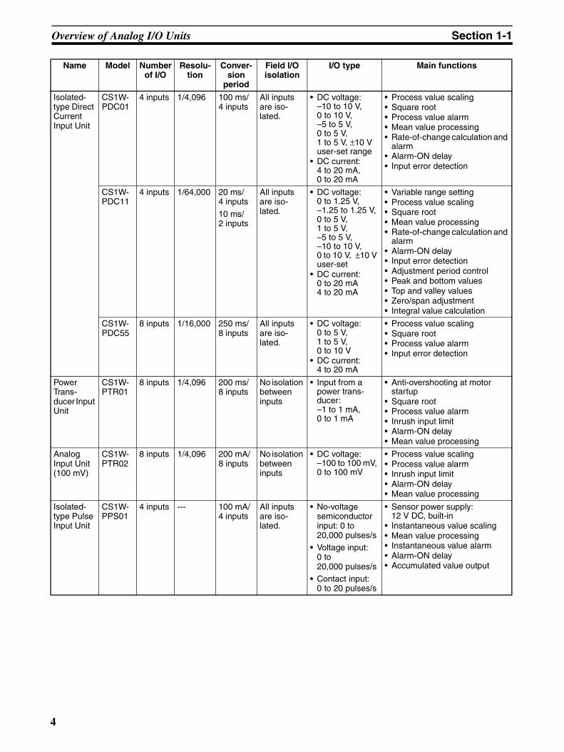
1-1-1 CS-series Analog I/O UnitsThere are 18 Analog I/O Unit models, as shown in the following table.
Name Model Number of I/O
Resolu-tion
Conver-sion
period
Field I/O isolation
I/O type Main functions
Isolated-type Ther-mocouple Input Unit
CS1W-PTS01-V1
4 inputs 1/4,096 150 ms/ 4 inputs
All inputs are iso-lated.
• Thermocouple:B, E, J, K, N, R, S, T, mV
• Variable range setting• Process value scaling• Process value alarm• Mean value processing• Rate-of-change calculation and
alarm• Alarm-ON delay• Disconnection detection
CS1W-PTS11
4 inputs 1/64,000 20 ms/ 4 inputs10 ms/ 2 inputs
All inputs are iso-lated.
• Thermocouple: B, E, J, K, L, N, R, S, T, U, WRe5-26, PL II
• DC voltage: ±100 mV
• Variable range setting• Process value scaling• Process value alarm• Mean value processing• Rate-of-change calculation and
alarm• Alarm-ON delay• Disconnection detection• Adjustment period control• Peak and bottom values• Top and valley values• Zero/span adjustment
CS1W-PTS51
4 inputs --- 250 ms/ 4 inputs
All inputs are iso-lated.
• Thermocouple: B, J, K, L, R, S, T
• Process value alarm (with external alarm)
• Sensor error detection• Alarm-ON delay• Zero/span adjustment
CS1W-PTS55
8 inputs --- 250 ms/ 8 inputs
All inputs are iso-lated.
• Thermocouple: B, J, K, L, R, S, T
• Process value alarm• Sensor error detection• Alarm-ON delay• Zero/span adjustment
Isolated-type Resis-tance Thermom-eter Input Unit (Pt100, JPt100)
CS1W-PTS02
4 inputs 1/4,096 100 ms/ 4 inputs
All inputs are iso-lated.
• Resistance ther-mometer: Pt100 (JIS, IEC), JPt100
• Variable range setting• Process value scaling• Process value alarm• Mean value processing• Rate-of-change calculation and
alarm• Alarm-ON delay• Disconnection detection
Isolated-type Resis-tance Thermom-eter Input Unit (Ni508.4)
CS1W-PTS03
4 inputs 1/4,096 100 ms/ 4 inputs
All inputs are iso-lated.
• Resistance ther-mometer:Ni508.4
• Variable range setting• Process value scaling• Process value alarm• Mean value processing• Rate-of-change calculation and
alarm• Alarm-ON delay• Disconnection detection
2

Overview of Analog I/O Units Section 1-1
Isolated-type Resis-tance Thermom-eter Input Unit (Pt100, JPt100, Pt50, Ni508.4)
CS1W-PTS12
4 inputs 1/64,000 20 ms/ 4 inputs10 ms/ 2 inputs
All inputs are iso-lated.
• Resistance ther-mometer: Pt100, JPt100, Pt50, Ni508.4
• Variable range setting• Process value scaling• Process value alarm• Mean value processing• Rate-of-change calculation and
alarm• Alarm-ON delay• Disconnection detection• Adjustment period control• Peak and bottom values• Top and valley values• Zero/span adjustment
Isolated-type Resis-tance Thermom-eter Input Unit (Pt100, JPt100)
CS1W-PTS52
4 inputs --- 250 ms/ 4 inputs
All inputs are iso-lated.
• Resistance ther-mometer: Pt100 (JIS, IEC), JPt100
• Process value alarm (with external alarm)
• Sensor error detection• Alarm-ON delay• Zero/span adjustment
Isolated-type Resis-tance Thermom-eter Input Unit (Pt100, JPt100)
CS1W-PTS56
8 inputs --- 250 ms/ 8 inputs
All inputs are iso-lated.
• Resistance ther-mometer: Pt100 (JIS, IEC), JPt100
• Process value alarm• Sensor error detection• Alarm-ON delay• Zero/span adjustment
Isolated-type 2-Wire Transmit-ter Input Unit
CS1W-PTW01
4 inputs 1/4,096 100 ms/ 4 inputs
All inputs are iso-lated.
4 to 20 mA from 2-wire transmitter.• DC current:
4 to 20 mA• DC voltage:
1 to 5 V
• Built-in power supply for 2-wire transmitter
• Process value scaling• Process value alarm• Mean value processing• Rate-of-change calculation and
alarm• Alarm-ON delay• Input error detection
Name Model Number of I/O
Resolu-tion
Conver-sion
period
Field I/O isolation
I/O type Main functions
3
Overview of Analog I/O Units Section 1-1
Isolated-type Direct Current Input Unit
CS1W-PDC01
4 inputs 1/4,096 100 ms/ 4 inputs
All inputs are iso-lated.
• DC voltage:–10 to 10 V, 0 to 10 V, –5 to 5 V, 0 to 5 V, 1 to 5 V, ±10 V user-set range
• DC current:4 to 20 mA, 0 to 20 mA
• Process value scaling• Square root• Process value alarm• Mean value processing• Rate-of-change calculation and
alarm• Alarm-ON delay• Input error detection
CS1W-PDC11
4 inputs 1/64,000 20 ms/ 4 inputs
10 ms/ 2 inputs
All inputs are iso-lated.
• DC voltage:0 to 1.25 V, –1.25 to 1.25 V, 0 to 5 V, 1 to 5 V, –5 to 5 V, –10 to 10 V, 0 to 10 V, ±10 V user-set
• DC current:0 to 20 mA4 to 20 mA
• Variable range setting• Process value scaling• Square root• Mean value processing• Rate-of-change calculation and
alarm• Alarm-ON delay• Input error detection• Adjustment period control• Peak and bottom values• Top and valley values• Zero/span adjustment• Integral value calculation
CS1W-PDC55
8 inputs 1/16,000 250 ms/ 8 inputs
All inputs are iso-lated.
• DC voltage:0 to 5 V, 1 to 5 V, 0 to 10 V
• DC current:4 to 20 mA
• Process value scaling• Square root• Process value alarm• Input error detection
Power Trans-ducer Input Unit
CS1W-PTR01
8 inputs 1/4,096 200 ms/ 8 inputs
No isolation between inputs
• Input from a power trans-ducer:–1 to 1 mA, 0 to 1 mA
• Anti-overshooting at motor startup
• Square root• Process value alarm• Inrush input limit• Alarm-ON delay• Mean value processing
Analog Input Unit(100 mV)
CS1W-PTR02
8 inputs 1/4,096 200 mA/ 8 inputs
No isolation between inputs
• DC voltage:–100 to 100 mV, 0 to 100 mV
• Process value scaling• Process value alarm• Inrush input limit• Alarm-ON delay• Mean value processing
Isolated-type Pulse Input Unit
CS1W-PPS01
4 inputs --- 100 mA/ 4 inputs
All inputs are iso-lated.
• No-voltage semiconductor input: 0 to 20,000 pulses/s
• Voltage input: 0 to 20,000 pulses/s
• Contact input: 0 to 20 pulses/s
• Sensor power supply:12 V DC, built-in
• Instantaneous value scaling• Mean value processing• Instantaneous value alarm• Alarm-ON delay• Accumulated value output
Name Model Number of I/O
Resolu-tion
Conver-sion
period
Field I/O isolation
I/O type Main functions
4
Overview of Analog I/O Units Section 1-1
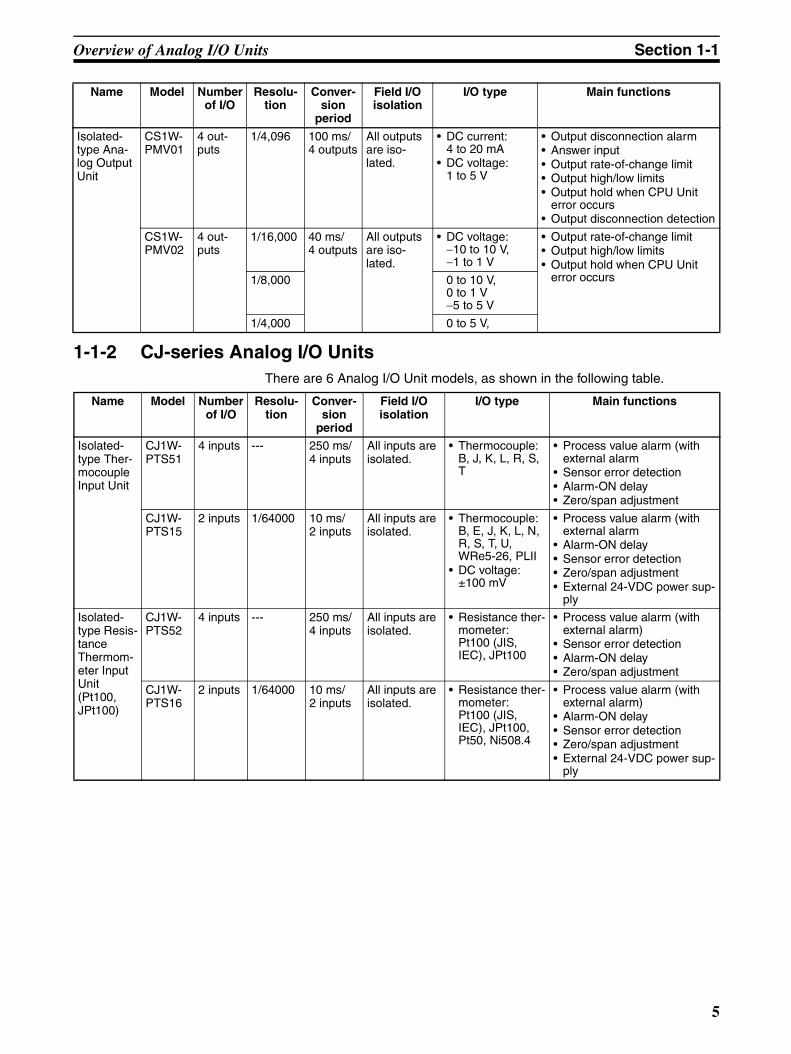
1-1-2 CJ-series Analog I/O UnitsThere are 6 Analog I/O Unit models, as shown in the following table.
Isolated-type Ana-log Output Unit
CS1W-PMV01
4 out-puts
1/4,096 100 ms/ 4 outputs
All outputs are iso-lated.
• DC current:4 to 20 mA
• DC voltage:1 to 5 V
• Output disconnection alarm• Answer input• Output rate-of-change limit• Output high/low limits• Output hold when CPU Unit
error occurs• Output disconnection detection
CS1W-PMV02
4 out-puts
1/16,000 40 ms/ 4 outputs
All outputs are iso-lated.
• DC voltage:−10 to 10 V, −1 to 1 V
• Output rate-of-change limit• Output high/low limits• Output hold when CPU Unit
error occurs1/8,000 0 to 10 V, 0 to 1 V−5 to 5 V
1/4,000 0 to 5 V,
Name Model Number of I/O
Resolu-tion
Conver-sion
period
Field I/O isolation
I/O type Main functions
Name Model Number of I/O
Resolu-tion
Conver-sion
period
Field I/O isolation
I/O type Main functions
Isolated-type Ther-mocouple Input Unit
CJ1W-PTS51
4 inputs --- 250 ms/ 4 inputs
All inputs are isolated.
• Thermocouple: B, J, K, L, R, S, T
• Process value alarm (with external alarm
• Sensor error detection• Alarm-ON delay• Zero/span adjustment
CJ1W-PTS15
2 inputs 1/64000 10 ms/ 2 inputs
All inputs are isolated.
• Thermocouple: B, E, J, K, L, N, R, S, T, U, WRe5-26, PLII
• DC voltage:±100 mV
• Process value alarm (with external alarm
• Alarm-ON delay• Sensor error detection• Zero/span adjustment• External 24-VDC power sup-
ply
Isolated-type Resis-tance Thermom-eter Input Unit (Pt100, JPt100)
CJ1W-PTS52
4 inputs --- 250 ms/ 4 inputs
All inputs are isolated.
• Resistance ther-mometer: Pt100 (JIS, IEC), JPt100
• Process value alarm (with external alarm)
• Sensor error detection• Alarm-ON delay• Zero/span adjustment
CJ1W-PTS16
2 inputs 1/64000 10 ms/ 2 inputs
All inputs are isolated.
• Resistance ther-mometer: Pt100 (JIS, IEC), JPt100, Pt50, Ni508.4
• Process value alarm (with external alarm)
• Alarm-ON delay• Sensor error detection• Zero/span adjustment• External 24-VDC power sup-
ply
5

Overview of Analog I/O Units Section 1-1
Isolated-type Direct Current Input Unit
CJ1W-PDC15
2 inputs 1/64000 10 ms/ 2 inputs
All inputs are isolated.
• DC voltage0 to 1.25 V, −1.25 to +1.25 V, 0 to 5 V, 1 to 5 V, −5 to +5 V, 0 to 10 V, −10 to +10 V, ±10 V user set range
• DC current0 to 20 mA4 to 20 mA
• Variable range setting• Process value scaling• Square root processing• Mean value processing• Rate-of-change calculation
and alarm• Alarm-ON delay• Input error detection• Adjustment period control• Peak and bottom detection• Top and valley detection• Zero/span adjustment• Integral value calculation• External 24-VDC power sup-
ply
Isolated-type Uni-versal Input Unit
CJ1W-PH41U
4 inputs Select from the fol-lowing three modes:Mode 1:
Resolution: 1/256,000Conversion period: 60 ms/4 inputs
Mode 2:Resolution: 1/64,000Conversion period: 10 ms/4 inputs
Mode 3:Resolution: 1/16,000Conversion period: 5 ms/4 inputs
All inputs are isolated.
• Resistance ther-mometer: Pt100 (3-wire), JPt100, Pt1000, Pt100 (4-wire)
• Thermocouple K, J, T, E, L, U, N, R, S, B, WRe5-26, PLII
• DC voltage: 1 to 5 V, 0 to 1.25 V, 0 to 5 V, 0 to 10 V, ±100 mV, −1.25 to 1.25 V, −5 to 5 V, −10 to 10 V
• DC current: 0 to 20 mA, 4 to 20 mA
• Potentiometer
• Variable input range setting• Process value scaling• Offset compensation• Process value alarm• Rate-of-change calculation
and alarm• Alarm ON/OFF delay• Square root extraction• Mean value processing• Input error detection• Adjustment period control• Peak and bottom detection• Top and valley detection• Zero/span adjustment• Integral value calculation
Name Model Number of I/O
Resolu-tion
Conver-sion
period
Field I/O isolation
I/O type Main functions
6

Features and Functions Section 1-2
1-2 Features and FunctionsI/O Isolation The Analog I/O Units listed below have isolation between inputs or outputs.
Therefore sneak circuits do not occur between thermocouples or between thepower supply’s common voltage inputs, so there is no need to utilize a signalconverter to prevent sneak circuits.
Variable Input Range Setting
For the Analog I/O Units listed below, the input range can be set by the useraccording to the application. This function applies to the following Units:
Note The accuracy and resolution of the CS1W-PTS01-V1, CS1W-PTS02, andCS1W-PDC01 are in respect to the internal ranges.
Applicable Units Isolated-type Thermocouple Input Units
CS1W-PTS01-V1/11/51/55, CJ1W-PTS51/15
Isolated-type Resistance Thermometer Input Units
CS1W-PTS02/03/12/52/56, CJ1W-PTS52/16
Isolated-type 2-Wire Transmit-ter Input Unit
CS1W-PTW01
Isolated-type Direct Current Input Units
CS1W-PDC01/11/55, CJ1W-PDC15
Isolated-type Pulse Input Unit CS1W-PPS01
Isolated-type Analog Output Units
CS1W-PMV01/PMV02
Isolated-type Universal Input Unit
CJ1W-PH41U
Analog I/O Unit
Isolation
Isolation
Isolation
Applicable Units Isolated-type Thermocouple Input Units
CS1W-PTS01-V1/11, CJ1W-PTS15
Isolated-type Resistance Thermometer Input Units
CS1W-PTS02/12, CJ1W-PTS16
Isolated-type Direct Current Input Units
CS1W-PDC01/11, CJ1W-PDC15
Isolated-type Universal Input Unit
CJ1W-PH41U
Measurable temperature range
Zero Span
−200°C 1300°C
400°C
Operating temperature
range
7

Features and Functions Section 1-2
Process Value (or Instantaneous Value) Scaling in Industrial Units
This function takes the value scaled in industrial units with respect to the inputsignal’s zero point and span point, and transfers it to the CPU Unit as the pro-cess value. Because of this, no ladder program is required at the CPU Unit forscaling.
Note It also possible to set the process value scaling zero/span point in reverse tocreate an inverse relationship.
CS1W-PTS11/12, PDC11, CJ1W-PTS15/16, PDC15, PH41U
With the CS1W-PTS11/PTS12, PDC11, and CJ1W-PTS15/16, PDC15,PH41U, the input range for thermocouple inputs, and platinum-resistancethermometer inputs, or the user-set range for DC inputs can be set directly,and scaling can be set for the range in industrial units. This eliminates theneed for processing scaling in the ladder program.
Note It also possible to set the process value scaling zero/span points in reverse tocreate an inverse relationship.
Applicable Units Isolated-type Thermocouple Input Units
CS1W-PTS01-V1/11, CJ1W-PTS15
Isolated-type Resistance Thermometer Input Units
CS1W-PTS02/03/12, CJ1W-PTS16
Isolated-type 2-Wire Transmit-ter Input Unit
CS1W-PTW01
Isolated-type Direct Current Input Unit
CS1W-PDC01/11/55, PTR02, CJ1W-PDC15
Power Transducer Input Unit CS1W-PTR01
Isolated-type Pulse Input Unit CS1W-PPS01
Isolated-type Universal Input Unit
CJ1W-PH41U
Input signal
Industrial unit
4 20 mA
0 800 Pa
K thermocouple
Measured input range
Maximum input signal valueMinimum input signal value
0 10000
Minimum scaling value Maximum scaling value
Scaling range
−200°C
0°C 400°C
1300°C
Operating temperature range
8

Features and Functions Section 1-2
Offset Compensation
Offset compensation is possible for process value errors. The amount of theerror is added to the process value.
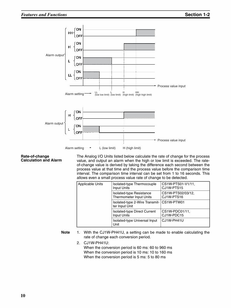
Process Value Alarm Either a 2-point alarm (H and L limits) or a 4-point alarm (HH, H, L, and LL lim-its) is possible for the process value (or instantaneous value).
CS1W-PTS51/52 and CJ1W-PTS51/52 Units have one external alarm outputfor each input. High or low outputs can be selected.CS1W-PTS55/PTS56 and PDC55 output alarms to the Expansion SettingArea. This enables obtaining alarm outputs without special programming.
Applicable Units Isolated-type Universal Input Unit
CJ1W-PH41U
Upper limit (7FFF FFFF hex)
Scaling upper limit
Scaling lower limit
Input range
Scaling offset value
Minimum input signal value
Maximum input signal value
Applicable Units
4-point alarm Isolated-type Ther-mocouple Input Units
CS1W-PTS01-V1/11, CJ1W-PTS15
Isolated-type Resis-tance Thermometer Input Units
CS1W-PTS02/03/12, CJ1W-PTS16
Isolated-type 2-Wire Transmitter Input Unit
CS1W-PTW01
Isolated-type Direct Current Input Units
CS1W-PDC01/11, PTR02, CJ1W-PDC15
Isolated-type Pulse Input Unit
CS1W-PPS01
Isolated-type Univer-sal Input Unit
CJ1W-PH41U
2-point alarm Isolated-type Ther-mocouple Input Units
CS1W-PTS51/55, CJ1W-PTS51
Isolated-type Resis-tance Thermometer Input Units
CS1W-PTS52/56, CJ1W-PTS52
Analog Input Unit (100 mV)
CS1WPTR02, CS1W-PDC55
Power Transducer Input Unit
CS1W-PTR01
9
Features and Functions Section 1-2
Rate-of-change Calculation and Alarm
The Analog I/O Units listed below calculate the rate of change for the processvalue, and output an alarm when the high or low limit is exceeded. The rate-of-change value is derived by taking the difference each second between theprocess value at that time and the process value before the comparison timeinterval. The comparison time interval can be set from 1 to 16 seconds. Thisallows even a small process value rate of change to be detected.
Note 1. With the CJ1W-PH41U, a setting can be made to enable calculating therate of change each conversion period.
2. CJ1W-PH41U:When the conversion period is 60 ms: 60 to 960 msWhen the conversion period is 10 ms: 10 to 160 msWhen the conversion period is 5 ms: 5 to 80 ms
Alarm output
Alarm output
Alarm setting
Alarm setting
LL (low low limit)
L (low limit)
H (high limit)
HH (high high limit)
Process value input
L (low limit) H (high limit)
Process value input
Applicable Units Isolated-type Thermocouple Input Units
CS1W-PTS01-V1/11, CJ1W-PTS15
Isolated-type Resistance Thermometer Input Units
CS1W-PTS02/03/12, CJ1W-PTS16
Isolated-type 2-Wire Transmit-ter Input Unit
CS1W-PTW01
Isolated-type Direct Current Input Units
CS1W-PDC01/11, CJ1W-PDC15
Isolated-type Universal Input Unit
CJ1W-PH41U
10
Features and Functions Section 1-2
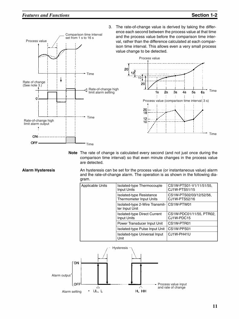
Note The rate of change is calculated every second (and not just once during thecomparison time interval) so that even minute changes in the process valueare detected.
Alarm Hysteresis An hysteresis can be set for the process value (or instantaneous value) alarmand the rate-of-change alarm. The operation is as shown in the following dia-gram.
Process value
Time
Process value
Time
Process value (comparison time interval: 3 s)
Time
Comparison time interval set from 1 s to 16 s
Rate of change(See note 3.)
Rate-of-change high limit alarm setting
TimeRate-of-change high limit alarm output
Time
10
3. The rate-of-change value is derived by taking the differ-ence each second between the process value at that timeand the process value before the comparison time inter-val, rather than the difference calculated at each compar-ison time interval. This allows even a very small processvalue change to be detected.
Applicable Units Isolated-type Thermocouple Input Units
CS1W-PTS01-V1/11/51/55, CJ1W-PTS51/15
Isolated-type Resistance Thermometer Input Units
CS1W-PTS02/03/12/52/56, CJ1W-PTS52/16
Isolated-type 2-Wire Transmit-ter Input Unit
CS1W-PTW01
Isolated-type Direct Current Input Units
CS1W-PDC01/11/55, PTR02, CJ1W-PDC15
Power Transducer Input Unit CS1W-PTR01
Isolated-type Pulse Input Unit CS1W-PPS01
Isolated-type Universal Input Unit
CJ1W-PH41U
Alarm output
Alarm setting
Hysteresis
Process value input and rate of change
11

Features and Functions Section 1-2
Alarm-ON Delay This function can be used to set a given time period (0 s to 60 s) for delayingthe turning ON of the alarm after the process value (or instantaneous value)alarm status or the alarm setting is reached. One alarm-ON delay is set foreach input or output. The same setting is used for all process value alarms(HH, H, L, LL) and rate-of-change alarms (H, L).
Applicable Units Isolated-type Thermocouple Input Units
CS1W-PTS01-V1/11/51/55, CJ1W-PTS51/15
Isolated-type Resistance Thermometer Input Units
CS1W-PTS02/03/12/52/56, CJ1W-PTS52/16
Isolated-type 2-Wire Transmit-ter Input Unit
CS1W-PTW01
Isolated-type Direct Current Input Units
CS1W-PDC01/11/55, PTR02, CJ1W-PDC15
Power Transducer Input Unit CS1W-PTR01
Isolated-type Pulse Input Unit CS1W-PPS01
Isolated-type Universal Input Unit
CJ1W-PH41U
Example: H alarm setting
Time
Alarm output
Time
ON delay time (0 s to 60 s)
Process value
12

Features and Functions Section 1-2
OFF-delay Outputs This function makes it possible to turn OFF the alarm signal after a set timeperiod (0 to 60 s) has elapsed after alarm status is cleared, rather than havingthe alarm turned OFF immediately.An alarm OFF-delay time can be set for each input. The process value alarms(HH, H, L, LL) and rate-of-change alarms (H, L) will all use the same OFF-delay time.
Mean Value Processing The moving average of a specified number (from 1 to 16) of past process val-ues (or instantaneous values) can be calculated and stored as the processvalue. An input noise filter can be installed if erroneous process values areobtained due to noise, or if the system has sudden voltage or current fluctua-tions.
Note For the CS1W-PTR01 and CS1W-PTR02, four process values are alwaysaveraged. For the CS1W-PTS11, CS1W-PTS12, CS1W-PDC11, CJ1W-PTS15, CJ1W-PTS16, CJ1W-PDC15 and CJ1W-PH41U the number of val-ues to be averaged can be set to between 1 and 128.
Applicable Units Isolated-type Universal Input Unit
CJ1W-PH41U
ON
OFF
Process value
Example: H (high) alarm setting
Alarm output
ON-delay time(0 to 60 s)
Time
Time
OFF-delay time(0 to 60 s)
Applicable Units Isolated-type Thermocouple Input Units
CS1W-PTS01-V1/11, CJ1W-PTS15
Isolated-type Resistance Thermometer Input Units
CS1W-PTS02/03/12, CJ1W-PTS16
Isolated-type 2-Wire Transmit-ter Input Unit
CS1W-PTW01
Isolated-type Direct Current Input Units
CS1W-PDC01/11, PTR02, CJ1W-PDC15
Power Transducer Input Unit CS1W-PTR01
Isolated-type Pulse Input Unit CS1W-PPS01
Isolated-type Universal Input Unit
CJ1W-PH41U
13

Features and Functions Section 1-2
Input Disconnection Detection
Sensor disconnections can be detected for thermocouple input and resistancethermometer input. Either the high (115%) or low (–15%) direction can bespecified for when a disconnection is detected.
Note For the CJ1W-PH41U, this is the Input Error Flag.
Input Error Detection An errors resulting from exceeding the high or low limits can be detected.
Note An input error will be detected for the CS1W-PTS5@ or CJ1W-PTS5@ if theinput exceeds 20 digits for the high or low limits of the sensor range.For the CS1W-PDC55, an input error will be detected if the input exceeds−5% or +105% for the internal range full span.
Analog Output Unit CPU Unit
Calculation of moving average
Applicable Units Isolated-type Thermocouple Input Units
CS1W-PTS01-V1/11, CJ1W-PTS15
Isolated-type Resistance Thermometer Input Units
CS1W-PTS02/03/12, CJ1W-PTS16
Isolated-type Universal Input Unit
CJ1W-PH41U (See note.)
Analog Input Unit
Disconnection Detection Flag (See note.)
CPU Unit
Process value
High/low designation: 115% or −15%
Applicable Units Isolated-type Thermocouple Input Units
CS1W-PTS51/55, CJ1W-PTS51
Isolated-type Resistance Thermometer Input Units
CS1W-PTS52/56, CJ1W-PTS52
Isolated-type 2-Wire Transmit-ter Input Unit
CS1W-PTW01-V1
Isolated-type Direct Current Input Units
CS1W-PDC01/11/55, CJ1W-PDC15
Isolated-type Universal Input Unit
CJ1W-PH41U
14

Features and Functions Section 1-2
Cold Junction Sensor Errors Detection
If a Thermocouple Input Unit or Universal Input Unit built-in cold junction sen-sor is disconnected, if short-circuiting occurs, or if an error occurs at the coldjunction sensor, the Cold Junction Error Flag will turn ON and the temperatureprocess value with no cold junction compensation will be stored in the CIOArea.
Note 1. If one of the two cold junction sensors is disconnected as described above,cold junction compensation will be stopped for all inputs.
2. There is only one cold junction sensor for the CS1W-PTS51 and theCJ1W-PH41U. There are two cold junction sensors for the CJ1W-PTS15.
Square Root For 2-wire transmitter input and analog input, this function takes as the pro-cess value the square root of the analog input value. It is used for operationssuch as calculating momentary flow based on the differential pressure inputfrom a differential pressure transmitter.With linear characteristics at an output of approximately 7% or less, an on-sitedifferential pressure transmitter’s zero-point adjustment can be performedwith this function enabled.
Note The square root function is enabled only when the maximum scaling value isgreater than the minimum scaling value. Square root extraction will not bepossible if the minimum scaling value is greater.
Note 1. Enabled for DC input only.
2. The square root function can be used with the CS1W-PDC55 only whenusing the 1 to 5 V or 4 to 40 mA range.
Applicable Units Isolated-type Thermocouple Input Units
CS1W-PTS01-V1/11/51/55, CJ1W-PTS51/15
Isolated-type Universal Input Unit
CJ1W-PH41U
Applicable Units Isolated-type Direct Current Input Units
CS1W-PDC01/11/55, CJ1W-PDC15
Isolated-type 2-Wire Transmit-ter Input Unit
CS1W-PTW01
Isolated-type Universal Input Units
CJ1W-PH41U (See note 1.)
Process value input
Input signal
100%
7%0%
4 20 mA
15
Features and Functions Section 1-2
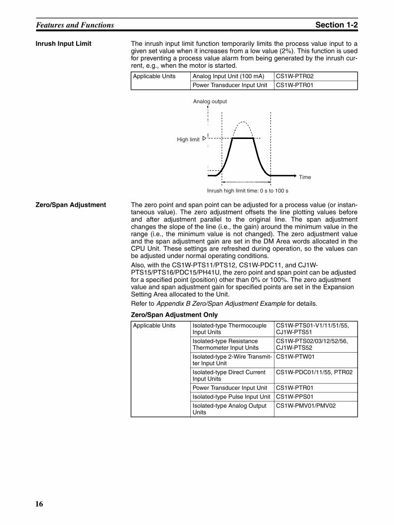
Inrush Input Limit The inrush input limit function temporarily limits the process value input to agiven set value when it increases from a low value (2%). This function is usedfor preventing a process value alarm from being generated by the inrush cur-rent, e.g., when the motor is started.
Zero/Span Adjustment The zero point and span point can be adjusted for a process value (or instan-taneous value). The zero adjustment offsets the line plotting values beforeand after adjustment parallel to the original line. The span adjustmentchanges the slope of the line (i.e., the gain) around the minimum value in therange (i.e., the minimum value is not changed). The zero adjustment valueand the span adjustment gain are set in the DM Area words allocated in theCPU Unit. These settings are refreshed during operation, so the values canbe adjusted under normal operating conditions.Also, with the CS1W-PTS11/PTS12, CS1W-PDC11, and CJ1W-PTS15/PTS16/PDC15/PH41U, the zero point and span point can be adjusted for a specified point (position) other than 0% or 100%. The zero adjustment value and span adjustment gain for specified points are set in the Expansion Setting Area allocated to the Unit. Refer to Appendix B Zero/Span Adjustment Example for details.
Zero/Span Adjustment Only
Applicable Units Analog Input Unit (100 mA) CS1W-PTR02
Power Transducer Input Unit CS1W-PTR01
Analog output
High limit
Time
Inrush high limit time: 0 s to 100 s
Applicable Units Isolated-type Thermocouple Input Units
CS1W-PTS01-V1/11/51/55, CJ1W-PTS51
Isolated-type Resistance Thermometer Input Units
CS1W-PTS02/03/12/52/56, CJ1W-PTS52
Isolated-type 2-Wire Transmit-ter Input Unit
CS1W-PTW01
Isolated-type Direct Current Input Units
CS1W-PDC01/11/55, PTR02
Power Transducer Input Unit CS1W-PTR01
Isolated-type Pulse Input Unit CS1W-PPS01
Isolated-type Analog Output Units
CS1W-PMV01/PMV02
16

Features and Functions Section 1-2
Zero/Span Adjustment and Zero/Span Adjustment for Specified Points
Stepdown This function reduces the number of pulses by 1/10, 1/100, or 1/1,000. It onlyoperates for an accumulating counter (and not for instantaneous values).Make this setting to prevent accumulating counter overflow. If the number ofpulses is 3,000, for example, setting the stepdown rate to 1/100 will reducethe number to 30, and the totalizing will then be based on that value.
Pulse Input Instantaneous Value Conversion
This function counts the number of pulses per time unit and converts the num-ber to an instantaneous value (pulses/time unit). Any of the following time
Applicable Units Isolated-type Thermocouple Input Unit
CS1W-PTS11, CJ1W-PTS15
Isolated-type Resistance Thermometer Input Unit
CS1W-PTS12, CJ1W-PTS16
Isolated-type Analog Input Unit
CS1W-PDC11, CJ1W-PDC15
Isolated-type Universal Input Unit
CJ1W-PH41U
DM Area
Always transferred
CPU Unit Analog I/O Unit
Adjustment data
Adjustment position
Span adjustment gain B
Zero adjustment value A
Expansion Memory Area allocation
Expansion Memory Area leading address
Expansion Setting Area (CJ1W-PTS15/-PTS16/ -PDC15/-PH41U only)
Area for Expansion Control/Monitor Area
First word of Expansion Control/Monitor Area
Span adjustment position D
Zero adjustment position C
Power ON orUnit restarted.
Before adjustment
After adjustment
Minimum range
Maximum range
Minimum range
Maximum range
Input
Output data
Zero adjustment value
Zero/Span Adjustment
Gain for span adjust-ment
Before adjustment
After adjustment
Minimum range
Maximum range
Minimum range
Maximum range
Input
Output data
Specified Point Zero/Span Adjustment with Expansion Setting Area Settings (CS1W-PTS11/PTS12, -PDC11, CJ1W-PTS15/16, PDC15, PH41U only)
Zero ad-justment value
Zero adjustment position
Span adjustment position
Gain for span ad-justment
Applicable Units Isolated-type Pulse Input Unit CS1W-PPS01
17

Features and Functions Section 1-2
units can be selected: 1 s, 3 s, 10 s, 30 s, or 60 s. (These match the cycles forconversion to instantaneous values.)When the number of pulses per time unit (i.e., pulse rate) is low, lengthen thetime unit. The instantaneous value stored, however, can only be refreshed atintervals of this time unit.If there is fluctuation in the instantaneous values, the moving average functioncan be used to even the values out through averaging. Calculate the movingaverage for the specified number of values, and then convert it to the numberof pulses per time unit. To determine the number of values for averaging,observe the operating status.
Pulse Accumulation Pulse Input Units can accumulate pulses within a range of 0 to 9,999 (0000 to270F hex). With each accumulation conversion period, the number of inputpulses after the stepdown is added. If the accumulated value exceeds 9,999,pulses are accumulated again from 0000. When the PLC is turned ON or theUnit is restarted, the accumulated value is reset to 0 and the AccumulationReset Bit turns ON for 10 seconds.
Answer Input During analog output, the actual analog output (current or voltage) signal canbe checked by being read again from the analog output terminals. This func-tion is used for checking for actual output load discrepancies due to externalload resistance, or for checking actual analog signal values when an outputrate-of-change limit is used.
Output Rate-of-change Limit
With this function, the analog output value’s rate of change can be limited sep-arately for the positive and negative directions.
Applicable Units Isolated-type Pulse Input Unit CS1W-PPS01
Applicable Units Isolated-type Pulse Input Unit CS1W-PPS01
Applicable Units Isolated-type Analog Output Unit
CS1W-PMV01
Output value
Rate-of-change limit
High/low limit
Answer input
(Actual output value)
Load
Analog Output Unit
Applicable Units Isolated-type Analog Output Units
CS1W-PMV01/PMV02
Analog output Without rate-of-change limit
With rate-of-change limit
Negative direction rate-of-change limit
Positive direction rate-of-change limit
Time
18
Features and Functions Section 1-2
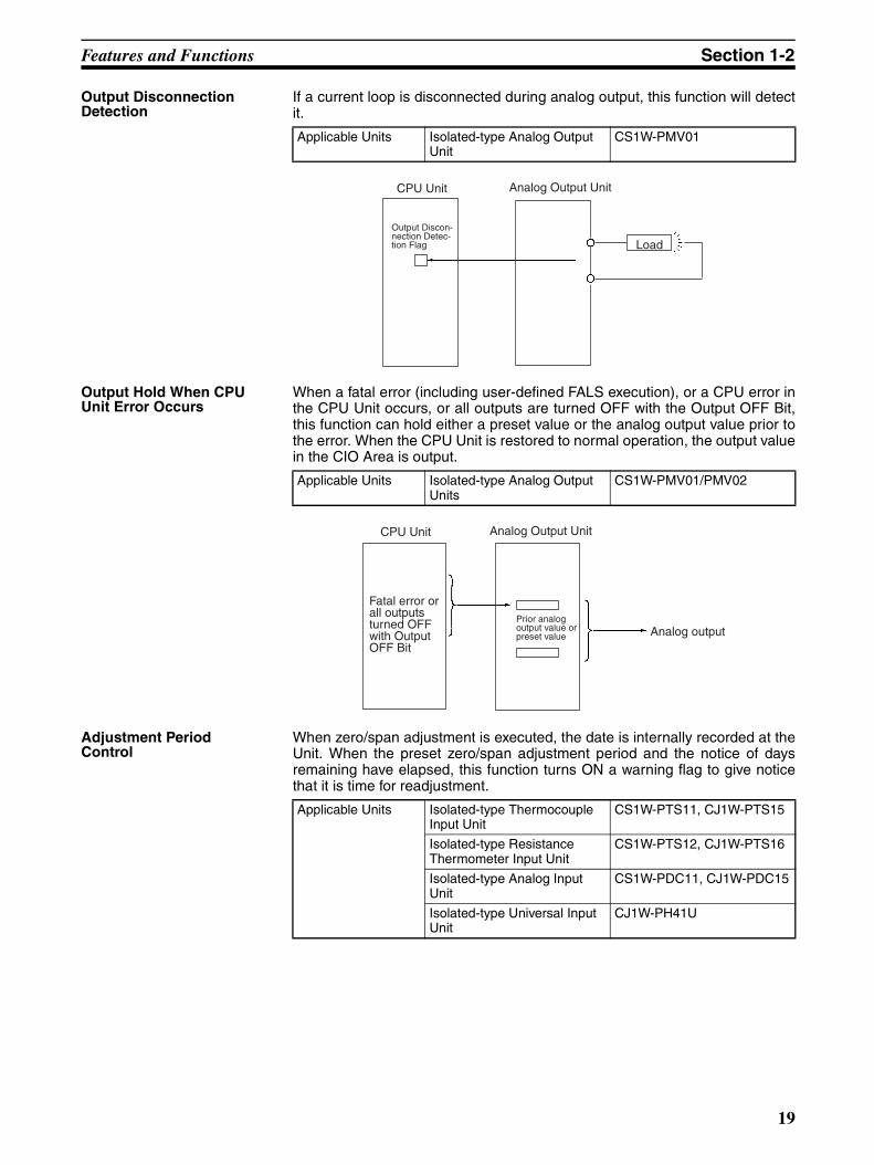
Output Disconnection Detection
If a current loop is disconnected during analog output, this function will detectit.
Output Hold When CPU Unit Error Occurs
When a fatal error (including user-defined FALS execution), or a CPU error inthe CPU Unit occurs, or all outputs are turned OFF with the Output OFF Bit,this function can hold either a preset value or the analog output value prior tothe error. When the CPU Unit is restored to normal operation, the output valuein the CIO Area is output.
Adjustment Period Control
When zero/span adjustment is executed, the date is internally recorded at theUnit. When the preset zero/span adjustment period and the notice of daysremaining have elapsed, this function turns ON a warning flag to give noticethat it is time for readjustment.
Applicable Units Isolated-type Analog Output Unit
CS1W-PMV01
CPU Unit Analog Output Unit
Load
Output Discon-nection Detec-tion Flag
Applicable Units Isolated-type Analog Output Units
CS1W-PMV01/PMV02
CPU Unit Analog Output Unit
Fatal error or all outputs turned OFF with Output OFF Bit
Prior analog output value or preset value Analog output
Applicable Units Isolated-type Thermocouple Input Unit
CS1W-PTS11, CJ1W-PTS15
Isolated-type Resistance Thermometer Input Unit
CS1W-PTS12, CJ1W-PTS16
Isolated-type Analog Input Unit
CS1W-PDC11, CJ1W-PDC15
Isolated-type Universal Input Unit
CJ1W-PH41U
19

Features and Functions Section 1-2
Peak and Bottom Detection
This function detects the maximum (peak) and minimum (bottom) analoginput values, from when the Hold Start Bit (output) allocated in the ExpansionControl/Monitor Area turns ON until it turns OFF. The peak and bottom valuesin the Expansion Control/Monitor Area are constantly refreshed, and they arecleared to zero while the Hold Value Reset Bit is ON.
DM Area
CPU Unit Analog I/O Unit
Comparison
Final adjustment date
Present date
Expansion Control/ Monitor Area
Example:Zero/span adjustment period = 180 days
July 3, 2002: Zero/span adjustment executed.
November 30, 2002: Adjustment Period Notice FlagDecember 30, 2002: Adjustment Period End Flag
Span adjustment gain B
Zero adjustment value A
Expansion Memory Area allocation
Expansion Memory Area leading address
Expansion Memory Area
Expansion Data Area allocation
Expansion Data Area leading address
Zero/span adjustment period
Notice of days remaining before zero/span adjust-ment period elapses
Adjustment Period End Flag
Adjustment Period Notice Flag
Continuously refreshed
Power ON or Unit restarted
Continuously refreshed
Continuously refreshed
Adjustment data
Notice of days remaining before zero/span adjustment period elapses = 30 days
Adjustment Update Bit
When Adjust-ment Update Bit is turned ON
Applicable Units Isolated-type Thermocouple Input Unit
CS1W-PTS11, CJ1W-PTS15
Isolated-type Resistance Thermometer Input Unit
CS1W-PTS12, CJ1W-PTS16
Isolated-type Analog Input Unit
CS1W-PDC11, CJ1W-PDC15
Isolated-type Universal Input Unit
CJ1W-PH41U
20

Features and Functions Section 1-2
Note The top and valley detection function and the peak and bottom detection func-tion cannot be used simultaneously.
Top and Valley Detection This function detects the top and valley values of the process value from whenthe Hold Start Bit (output) in the Expansion Control/Monitor Area turns ONuntil it turns OFF. A detection hysteresis can be set so that minute changesare not detected. The top and valley values in the Expansion Control/MonitorArea are constantly refreshed, and they are cleared to zero while the HoldValue Reset Bit is ON.
Hold Start Bit
Hold Value Reset Bit
Peak value
Process value
Bottom value
0
0
0
Applicable Units Isolated-type Thermocouple Input Unit
CS1W-PTS11, CJ1W-PTS15
Isolated-type Resistance Thermometer Input Unit
CS1W-PTS12, CJ1W-PTS16
Isolated-type Analog Input Unit
CS1W-PDC11, CJ1W-PDC15
Isolated-type Universal Input Unit
CJ1W-PH41U
21

Features and Functions Section 1-2
Note Either peak and bottom values or top and valley values can be selected fordetection. This selection is made by using the Hold Function Selection Flag inthe Expansion Control/Monitor Area to select either the top and valley detec-tion function or the peak and bottom detection function. These two functionscannot be used simultaneously.
Integral Value Calculation (CS1W-PDC11 and CJ1W-PDC15/PH41U Only)
This function calculates the integral of the process value over time. The unitcan be selected as either “hour” or “minute” by a setting in the Expansion Set-ting Area.The integral value can be output to the Expansion Monitor/Control Area byturning ON the Integral Value Calculation Start Bit in the Expansion Moni-tor/Control Area. It can also be cleared to zero by turning ON the IntegralValue Reset Bit in the Expansion Monitor/Control Area.In addition, with the CJ1W-PH41U, the integral value can be calculated usingan integral value coefficient to prevent integral value overflow.
Cold Junction Compensation Method
This function specifies whether cold junction compensation for thermocoupleinputs is to be performed in the Analog I/O Unit or externally. The externalmethod is enabled when the temperature difference is measured using two
Hold Start Bit
Hold Value Reset Bit
Top value
Analog input
0
0
0
Valley value
Applicable Units Isolated-type Analog Input Unit
CS1W-PDC11, CJ1W-PDC15
Isolated-type Universal Input Unit
CJ1W-PH41U
Time t
Integral width
Integral valueProcess value
22
Features and Functions Section 1-2
thermocouples or when an external cold-junction compensator is used forgreater precision.
Temperature Resistance Thermometer Compensation
This function performs compensation for resistance thermometer inputsaccording to the reference resistance for a connected resistance thermome-ter. Set the Temperature Resistance Thermometer Compensation Enable set-ting in the Expansion Setting Area to Enable and then set the ReferenceResistance (i.e., the resistance at 23°C) in the Expansion Setting Area.
Applicable Units Isolated-type Universal Input Units
CJ1W-PH41U
Applicable Units Isolated-type Universal Input Units
CJ1W-PH41U
23

System Configuration Section 1-3
1-3 System Configuration
CS Series These Analog I/O Units belong to the CS-series Special I/O Unit group.• They can be mounted to CS-series CPU Racks or Expansion I/O Racks.
• They cannot be mounted to C200H CPU Racks, Expansion I/O Racks, orSYSMAC BUS Remote I/O Slave Racks.
The number of Units that can be mounted to one Rack (either a CPU Rack orExpansion I/O Rack) depends upon the maximum current supplied by thePower Supply Unit and the current consumption by the other Units.There are no restrictions on Rack position.
Note I/O addresses for Special I/O Units are allocated according to the unit numberset on the switches on the front panel, and not according to the slot position inwhich they are mounted.
CJ Series These Analog I/O Units belong to the CJ-series Special I/O Unit group.• They can be mounted to CJ-series CPU Racks or Expansion I/O Racks.
The number of Units that can be mounted to one Rack (either a CPU Rack orExpansion I/O Rack) depends upon the maximum current supplied by thePower Supply Unit and the current consumption by the other Units.There are no restrictions on Rack position.
Note I/O addresses for Special I/O Units are allocated according to the unit numberset on the switches on the front panel, and not according to the slot position inwhich they are mounted.
CS-series CPU Rack
I/O UnitCPU Unit
CS-series Expansion I/O Rack #1
CS-series Expansion I/O Rack #2
CS-series Expansion I/O Rack #7
I/O Unit
I/O Unit
I/O Unit
Power Supply Unit
A maximum of 7 Expansion I/O Racks can be mounted.
24
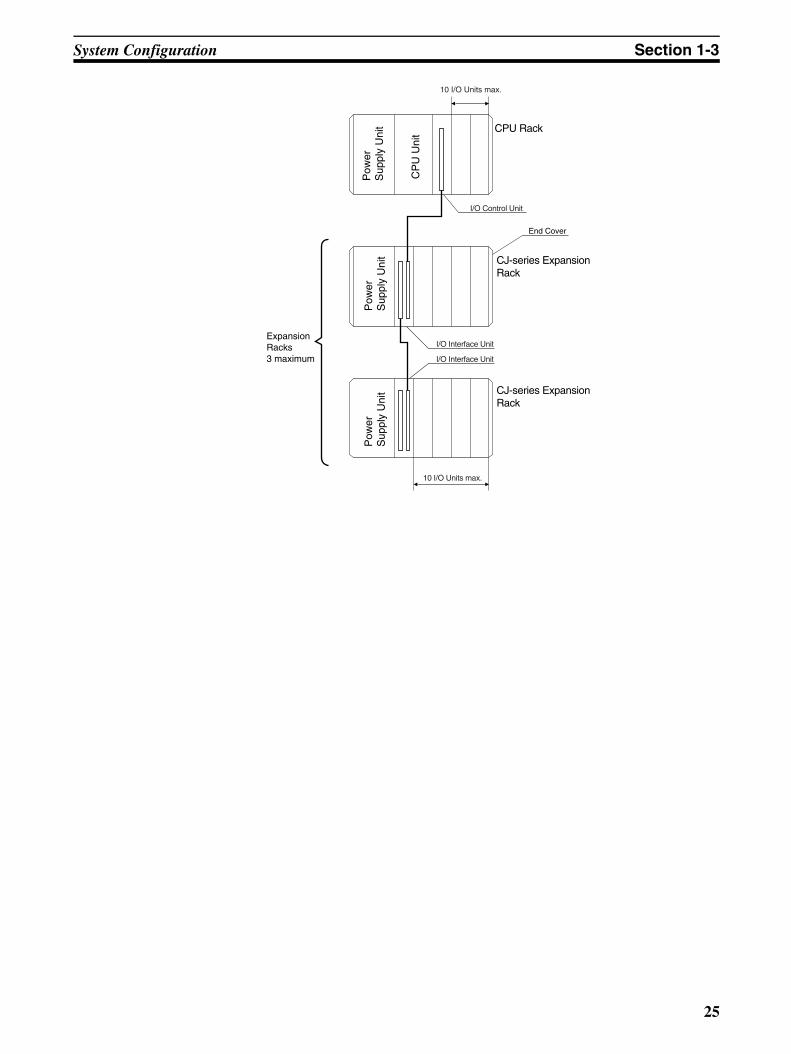
System Configuration Section 1-3
Pow
er
Sup
ply
Uni
t
CP
U U
nit
CJ-series ExpansionRack
CPU Rack
Pow
er
Sup
ply
Uni
tP
ower
S
uppl
y U
nit CJ-series Expansion
Rack
ExpansionRacks3 maximum
End Cover
10 I/O Units max.
I/O Control Unit
I/O Interface Unit
I/O Interface Unit
10 I/O Units max.
25

Specifications and Installation Section 1-4
1-4 Specifications and Installation
1-4-1 Specifications
CS Series The specifications shown in the following table apply to all the CS-series Ana-log I/O Units. For specifications and installation procedures specific to eachUnit, refer to the explanations in SECTION 2 Individual Unit Descriptions forCS Series.
Current consumption
Item Specification
Unit classification CS-series Special I/O Unit
Structure Backplane-mounted, single slot size
Dimensions 35 × 130 × 126 mm (W × H × D)
Weight 450 g max.
External connection ter-minals
• CS1W-PTS55/-PTS56/-PDC5524-point removable terminal block (with lever) (M3 screws, Tightening torque: 0.5 N·m)
• Other Units21-point removable terminal block (M3 screws, Tightening torque: 0.5 N·m)
Unit number switch set-ting
00 to 95
Self-diagnosis function Results of self-diagnosis shown on indicators.
Mountable Racks CPU Rack or CS-series Expansion Rack
Maximum number of Units
80 Units (10 Units × 8 Racks)Confirm that the total current consumption of all the Units (including the CPU Unit) mounted to a single CPU Rack or Expansion Rack does not exceed the maximum power supply capacity of the Power Supply Unit.
Ambient operating tem-perature
0 to 55°C
Ambient operating humidity
10% to 90% (with no condensation)
Name Model Current consumption (power)
5 V 26 V
Isolated-type Thermo-couple Input Unit
CS1W-PTS01-V1 0.15 A (0.75 W) 0.15 A (3.9 W)
CS1W-PTS11 0.16 A (0.60 W) 0.08 A (2.08 W)
CS1W-PTS51 0.25 A (1.25 W) Not used.
CS1W-PTS55 0.18 A (0.90 W) 0.06 A (1.56 W)
Isolated-type Resis-tance Thermometer Input Unit (Pt100, JPt100)
CS1W-PTS02 0.15 A (0.75 W) 0.15 A (3.9 W)
Isolated-type Resis-tance Thermometer Input Unit (Ni508.4)
CS1W-PTS03 0.15 A (0.75 W) 0.15 A (3.9 W)
Isolated-type Resis-tance Thermometer Input Unit (Pt100, JPt100, Pt50, Ni508.4)
CS1W-PTS12 0.12 A (0.60 W) 0.07 A (1.82 W)
Isolated-type Resis-tance Thermometer Input Unit (Pt100, JPt100)
CS1W-PTS52 0.25 A (1.25 W) Not used.
CS1W-PTS56 0.18 A (0.90 W) 0.06 A (1.56 W)
Isolated-type 2-Wire Transmitter Input Unit
CS1W-PTW01 0.15 A (0.75 W) 0.16 A (4.2 W)
26

Specifications and Installation Section 1-4
(Reference) Maximum current and total power supplied
CJ Series The specifications shown in the following table apply to all the CJ-series Ana-log I/O Units. For specifications and installation procedures specific to eachUnit, refer to the explanations in SECTION 3 Individual Unit Descriptions forCJ Series.
Current consumption
Isolated-type Direct Current Input Unit
CS1W-PDC01 0.15 A (0.75 W) 0.16 A (4.2 W)
CS1W-PDC11 0.12 A (0.60 W) 0.12 A (3.12 W)
CS1W-PDC55 0.18 A (0.90 W) 0.06 A (1.56 W)
Power Transducer Input Unit
CS1W-PTR01 0.15 A (0.75 W) 0.08 A (2.1 W)
Analog Input Unit (100 mV)
CS1W-PTR02 0.15 A (0.75 W) 0.08 A (2.1 W)
Isolated-type Pulse Input Unit
CS1W-PPS01 0.20 A (1.00 W) 0.16 A (4.2 W)
Isolated-type Analog Output Unit
CS1W-PMV01 0.15 A (0.75 W) 0.16 A (4.2 W)
CS1W-PMV02 0.12 A (0.60 W) 0.12 A (3.2 W)
Power Supply Unit
Maximum current supplied (power) Maximum total power5 V 26 V 24 V
C200HW-PA204 4.6 A (23 W) 0.6 A (15.6 W) None 30 W
C200HW-PA204C 4.6 A (23 W) 0.6 A (15.6 W) None 30 W
C200HW-PA204S 4.6 A (23 W) 0.6 A (15.6 W) 0.8 A (19.2 W) 30 W
C200HW-PA204R 4.6 A (23 W) 0.6 A (15.6 W) None 30 W
C200HW-PD024 4.6 A (23 W) 0.6 A (15.6 W) None 30 W
C200HW-PA209R 9 A (45 W) 1.3 A (33.8 W) None 45 W
C200HW-PD025 5.3 A 1.3 A None 40 W
CS1D-PA207R 7 A (35 W) 1.3 A (33.8 W) None 35 W
CS1D-PD024 4.3 A (21.5 W) 0.56 A (14.6 W) None 28 W
CS1D-PD025 5.3 A 1.3 A None 40 W
Name Model Current consumption (power)
5 V 26 V
Item Specification
Unit classification CJ-series Special I/O Unit
Dimensions 31 × 90 × 65 mm (W × H × D)
Weight 150 g max.
Maximum number of Units
40 Units (10 Units × 4 Racks)Confirm that the total current consumption of all the Units (including the CPU Unit) mounted to a single CPU Rack or Expansion Rack does not exceed the maximum power supplied by the Power Supply Unit.
Ambient operating temperature
0 to 55°C
Ambient operating humidity
10% to 90% (with no condensation)
Name Model Current consumption (power)
5 V 24-V external
Isolated-type Thermo-couple Input Unit
CJ1W-PTS51 0.25 A (1.25 W) Not used.
CJ1W-PTS15 0.18 A (0.9 W) 0.06 A
27

Specifications and Installation Section 1-4
(Reference) Maximum current and total power supplied
1-4-2 Nomenclature and Functions
CS Series
CS1W-P@@0@/1@/51/52
Note 1. The Terminal Block is detachable, with connectors. It can be removed byloosening the two black screws (on the top and bottom).
2. Always confirm that the black Terminal Block mounting screws are tight-ened to a torque of 0.5 N·m.
Isolated-type Resistance Thermometer Input Unit (Pt100, JPt100)
CJ1W-PTS52 0.25 A (1.25 W) Not used.
CJ1W-PTS16 0.18 A (0.9 W) 0.07 A
Isolated-type Direct Cur-rent Input Unit
CJ1W-PDC15 0.18 A (0.9 W) 0.09 A
Isolated-type Universal Input Unit
CJ1W-PH41U 0.30 A (1.5 W) Not used.
Power Supply Unit Maximum current supplied (power) Maximum total power5 V 24-V relay driver
current
CJ1W-PA205R/ PA205C
5.0 A (25 W) 0.8 A 25 W
CJ1W-PA202 2.8 A (14 W) 0.4 A 14 W
CJ1W-PD025 5.0 A (25 W) 0.8 A 25 W
CJ1W-PD022 2.0 A (10 W) 0.4 A 19.6 W
Name Model Current consumption (power)
5 V 24-V external
With Terminal Block mounted
Fastening screws (black M3 screws)
Model number
Unit number switch
Terminal Block (M3 screws)
Terminal number/symbol(Varies depending on the Analog I/O Unit model.)
Terminal Block
(Side view)
Backplane fastening screw
28
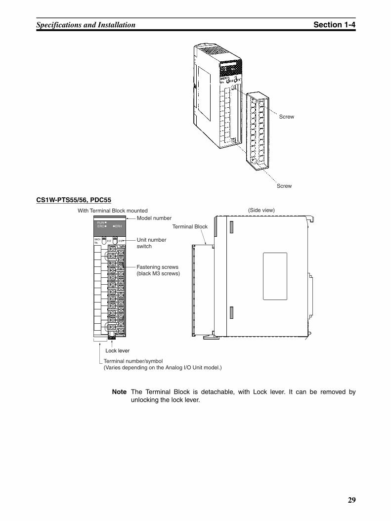
Specifications and Installation Section 1-4
CS1W-PTS55/56, PDC55
Note The Terminal Block is detachable, with Lock lever. It can be removed byunlocking the lock lever.
Screw
Screw
MACHNo.
X100X101
RUNERC ERH
Lock lever
With Terminal Block mountedModel number
Unit number switch
Fastening screws (black M3 screws)
Terminal number/symbol(Varies depending on the Analog I/O Unit model.)
Terminal Block
(Side view)
29

Specifications and Installation Section 1-4
Front Panel LED Indicators
CS1W-P@@0@/1@
CS1W-PTS55/56, PDC55
MACHNo.
X100FEDCBA9876543210
FEDCBA9876543210
X101
RUNERC
ERH
Lock lever
LED Meaning Indicator Operating status
RUN (green)
Operating Lit Operating normally.
Not lit Unit has stopped exchanging data with the CPU Unit.
ERC (red)
Error detected by Unit
Lit Data setting is out of range in the DM Area.
Not lit Operating normally.
ERH (red)
Error in the CPU Unit
Lit Error has occurred during data exchange with the CPU Unit, or Analog I/O Unit’s unit number is set incorrectly, or there is a mounting error.
Not lit Operating normally.
RUNERC ERH
CS
LED Meaning Indicator Operating status
RUN (green)
Operating Lit Operating normally.
Not lit Unit has stopped exchanging data with the CPU Unit.
ERC (red)
Error detected by Unit
Lit Sensor error has occurred or data setting is out of range in the DM Area.
Not lit Operating normally.
RUNERC ERH
CS
30

Specifications and Installation Section 1-4
CS1W-PTS51/52
Unit Number Switches The CPU Unit and Analog Input Unit exchange data via words allocated to theAnalog Input Unit as a Special I/O Unit. Words are allocated to Special I/OUnits in both the CIO Area and the DM Area.The words that each Analog I/O Unit uses are determined by the setting of theunit number switches on the front panel of the Unit.
ERH (red)
Error in the CPU Unit
Lit Error has occurred during data exchange with the CPU Unit, or Analog I/O Unit’s unit number is set incorrectly, or there is a mounting error.
Not lit Operating normally.
LED Meaning Indicator Operating status
LED Meaning Indicator Operating status
RUN (green)
Operating Lit Operating normally.
Not lit Unit has stopped exchanging data with the CPU Unit.
ERC (red)
Error detected by Unit
Lit Sensor error has occurred or data setting is out of range in the DM Area.
Not lit Operating normally.
ERH (red)
Error in the CPU Unit
Lit Error has occurred during data exchange with the CPU Unit, or Analog I/O Unit’s unit number is set incorrectly, or there is a mounting error.
Not lit Operating normally.
ALM1 to ALM4 (yellow)
External alarm outputs
Lit External alarm output ON
Not lit External alarm output OFF
RUNERC
ALM1ALM2
ERH
ALM3ALM4
CSPTS51
Unit No. CIO Area addresses DM Area addresses
0 CIO 2000 to CIO 2009 D20000 to D20099
1 CIO 2010 to CIO 2019 D20100 to D20199
2 CIO 2020 to CIO 2029 D20200 to D20299
3 CIO 2030 to CIO 2039 D20300 to D20399
4 CIO 2040 to CIO 2049 D20400 to D20499
5 CIO 2050 to CIO 2059 D20500 to D20599
6 CIO 2060 to CIO 2069 D20600 to D20699
7 CIO 2070 to CIO 2079 D20700 to D20799
8 CIO 2080 to CIO 2089 D20800 to D20899
9 CIO 2090 to CIO 2099 D20900 to D20999
10 CIO 2100 to CIO 2109 D21000 to D21099
to to to
Unit number switches
31
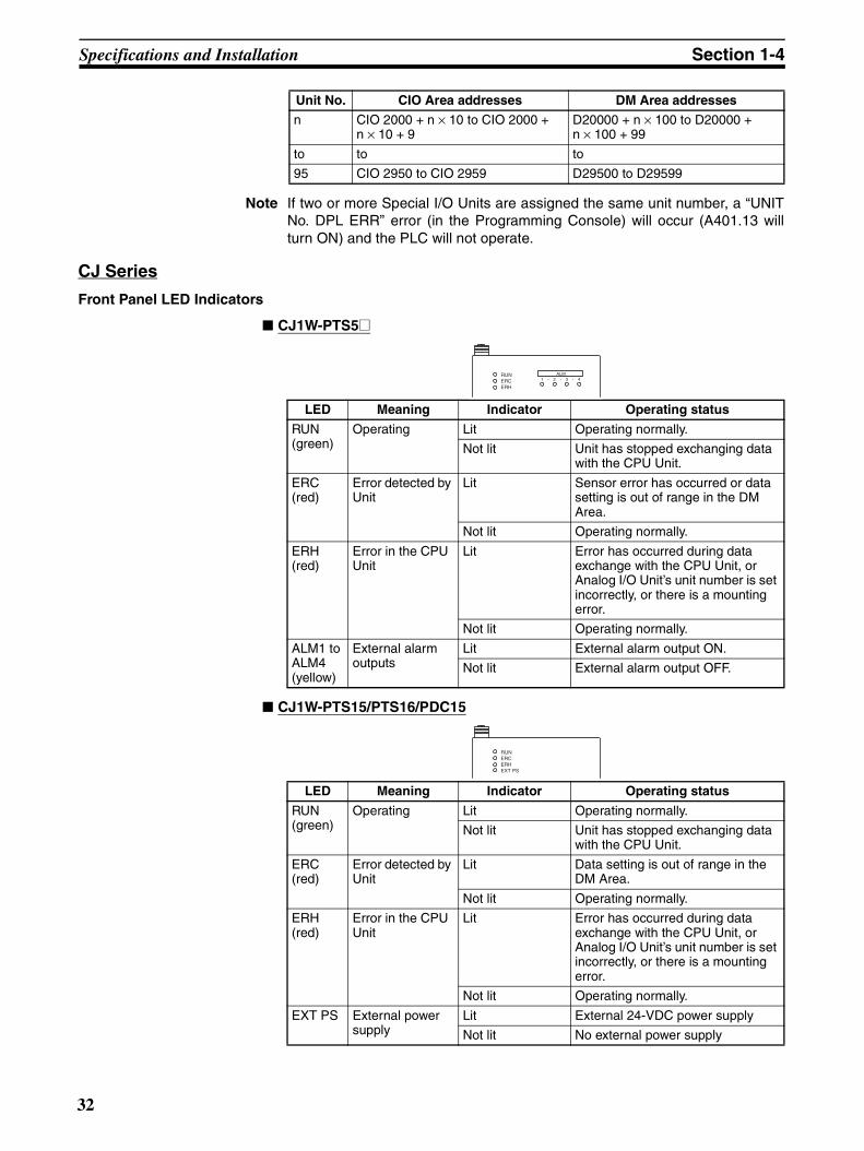
Specifications and Installation Section 1-4
Note If two or more Special I/O Units are assigned the same unit number, a “UNITNo. DPL ERR” error (in the Programming Console) will occur (A401.13 willturn ON) and the PLC will not operate.
CJ Series
Front Panel LED Indicators
CJ1W-PTS5@
CJ1W-PTS15/PTS16/PDC15
n CIO 2000 + n × 10 to CIO 2000 + n × 10 + 9
D20000 + n × 100 to D20000 + n × 100 + 99
to to to
95 CIO 2950 to CIO 2959 D29500 to D29599
Unit No. CIO Area addresses DM Area addresses
LED Meaning Indicator Operating status
RUN (green)
Operating Lit Operating normally.
Not lit Unit has stopped exchanging data with the CPU Unit.
ERC (red)
Error detected by Unit
Lit Sensor error has occurred or data setting is out of range in the DM Area.
Not lit Operating normally.
ERH (red)
Error in the CPU Unit
Lit Error has occurred during data exchange with the CPU Unit, or Analog I/O Unit’s unit number is set incorrectly, or there is a mounting error.
Not lit Operating normally.
ALM1 to ALM4 (yellow)
External alarm outputs
Lit External alarm output ON.
Not lit External alarm output OFF.
RUNERCERH
ALM1 2 3 4- - -
LED Meaning Indicator Operating status
RUN (green)
Operating Lit Operating normally.
Not lit Unit has stopped exchanging data with the CPU Unit.
ERC (red)
Error detected by Unit
Lit Data setting is out of range in the DM Area.
Not lit Operating normally.
ERH (red)
Error in the CPU Unit
Lit Error has occurred during data exchange with the CPU Unit, or Analog I/O Unit’s unit number is set incorrectly, or there is a mounting error.
Not lit Operating normally.
EXT PS External power supply
Lit External 24-VDC power supply
Not lit No external power supply
RUNERCERHEXT PS
32

Specifications and Installation Section 1-4
CJ1W-PH41U
Unit Number Switches The CPU Unit and Analog Input Unit exchange data via words allocated to theAnalog Input Unit as a Special I/O Unit. Words are allocated to Special I/OUnits in both the CIO Area and the DM Area.The words that each Analog I/O Unit uses are determined by the setting of theunit number switches on the front panel of the Unit.
Note If two or more Special I/O Units are assigned the same unit number, a “UNITNo. DPL ERR” error (in the Programming Console) will occur (A401.13 willturn ON) and the PLC will not operate.
LED Meaning Indicator Operating status
RUN (green)
Operating Lit Operating normally.
Not lit Unit has stopped exchanging data with the CPU Unit.
ERC (red)
Error detected by Unit
Lit Data setting is out of range in the DM Area.
Not lit Operating normally.
ERH (red)
Error in the CPU Unit
Lit Error has occurred during data exchange with the CPU Unit, or Analog I/O Unit’s unit number is set incorrectly, or there is a mounting error.
Not lit Operating normally.
P H 41U
RUNERCERH
Unit No. CIO Area addresses DM Area addresses
0 CIO 2000 to CIO 2009 D20000 to D20099
1 CIO 2010 to CIO 2019 D20100 to D20199
2 CIO 2020 to CIO 2029 D20200 to D20299
3 CIO 2030 to CIO 2039 D20300 to D20399
4 CIO 2040 to CIO 2049 D20400 to D20499
5 CIO 2050 to CIO 2059 D20500 to D20599
6 CIO 2060 to CIO 2069 D20600 to D20699
7 CIO 2070 to CIO 2079 D20700 to D20799
8 CIO 2080 to CIO 2089 D20800 to D20899
9 CIO 2090 to CIO 2099 D20900 to D20999
10 CIO 2100 to CIO 2109 D21000 to D21099
to to to
n CIO 2000 + n × 10 to CIO 2000 + n × 10 + 9
D20000 + n × 100 to D20000 + n × 100 + 99
to to to
95 CIO 2950 to CIO 2959 D29500 to D29599
MACHNo.X101
Unit Number Switches
MACHNo.X100
0123
45678
9
0123
45678
9
33

Specifications and Installation Section 1-4
1-4-3 Exchanging Data with the CPU Unit
CS1W-PTS01-V1, PTS02/03/51/52, PTW01, PDC01, PTR01/02, PMV01/02, CJ1W-PTS51/52
The Analog I/O Unit exchanges data with the CPU Unit via the allocated por-tions of the CPU Unit’s Special I/O Unit Area and DM Area. The addressesallocated in these areas are determined as follows, according to the value (0to 95) set by the unit number switch on the front panel of the Analog I/O Unit.
• Special I/O Unit Area: 10 words from beginning word nn = 2000 + unit number (0 to 95) x 10
• DM Area: 100 words from beginning word mm = D20000 + unit number (0 to 95) x 100
The following table shows the addresses allocated according to the unit num-ber.
Note 1. This applies when word m contains other than 12345 (3039 hex), e.g.,0000 hex. When word m contains 12345 (3039 hex), the transfer directionwill be reversed.
2. The functions that can be used depend on the model.
Unit No. Special I/O Unit Area DM Area
0 CIO 2000 to CIO 2009 D20000 to D20099
1 CIO 2010 to CIO 2019 D20100 to D20199
2 CIO 2020 to CIO 2029 D20200 to D20299
3 CIO 2030 to CIO 2039 D20300 to D20399
4 CIO 2040 to CIO 2049 D20400 to D20499
5 CIO 2050 to CIO 2059 D20500 to D20599
6 CIO 2060 to CIO 2069 D20600 to D20699
7 CIO 2070 to CIO 2079 D20700 to D20799
8 CIO 2080 to CIO 2089 D20800 to D20899
9 CIO 2090 to CIO 2099 D20900 to D20999
10 CIO 2100 to CIO 2109 D21000 to D21099
to to to
95 CIO 2950 to CIO 2959 D29500 to D29599
CPU Unit Analog I/O Unit
Special I/O Unit Area
n = 2000 + (unit No. x 10)
DM Aream = D20000 + (unit No. x 100)
Default block read command
Setting Group 1
Setting Group 2
I/O refresh
Power ON or Unit restarted.
Data for OperationProcess values, analog output valuesRates of changeError flags
Unit Settings
Default transfer reception
Continuously Refreshed AreaAlarm settings, zero/spanAdjustment values, etc.
Area Refreshed at Restart
I/O refresh
(See note 1.)
Power ON or Unit restarted.
Power ON or Unit restarted.
(See note 1.)
to
nn+1
n+9
m
m+1
m+34
m+99
Display Parameterm+93
m+94
to
to
to
Initial values for sensor/input signal types, scaling, etc.
(See note 2.)
(See note 3.)
34
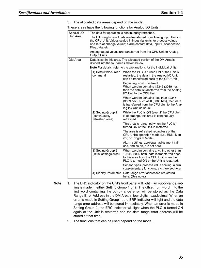
Specifications and Installation Section 1-4
3. The allocated data areas depend on the model.
These areas have the following functions for Analog I/O Units.
Note 1. The ERC indicator on the Unit's front panel will light if an out-of-range set-ting is made in either Setting Group 1 or 2. The offset from word m to thefirst word containing the out-of-range error will be stored as the DataRange Error Address in the DM Area in four digits hexadecimal. When anerror is made in Setting Group 1, the ERR indicator will light and the datarange error address will be stored immediately. When an error is made inSetting Group 2, the ERC indicator will light when the PLC is turned ONagain or the Unit is restarted and the data range error address will bestored at that time.
2. The functions that can be used depend on the model.
Special I/O Unit Area
The data for operation is continuously refreshed.The following types of data are transferred from Analog Input Units to the CPU Unit: Values scaled in industrial units for process values and rate-of-change values; alarm contact data, Input Disconnection Flag data, etc.Analog output values are transferred from the CPU Unit to Analog Output Units.
DM Area Data is set in this area. The allocated portion of the DM Area is divided into the four areas shown below.
Note For details, refer to the explanations for the individual Units.
1) Default block read command
When the PLC is turned ON or the Unit is restarted, the data in the Analog I/O Unit can be transferred back to the CPU Unit.Beginning word m is fixed. When word m contains 12345 (3039 hex), then the data is transferred from the Analog I/O Unit to the CPU Unit.
When word m contains less than 12345 (3039 hex), such as 0 (0000 hex), then data is transferred from the CPU Unit to the Ana-log I/O Unit as usual.
2) Setting Group 1 (continuously refreshed area)
While the PLC is ON (even if the CPU Unit is operating), this area is continuously refreshed.This area is refreshed when the PLC is turned ON or the Unit is restarted.
The area is refreshed regardless of the CPU Unit’s operation mode (i.e., RUN, Mon-itor, or Program Mode).Alarm settings, zero/span adjustment val-ues, and so on, are set here.
3) Setting Group 2 (initial settings area)
When word m contains anything other than 12345 (3039 hex), data is transferred once to this area from the CPU Unit when the PLC is turned ON or the Unit is restarted.Sensor types, process value scaling, alarm supplementary functions, etc., are set here.
4) Display Parameter Data range error addresses are stored here. (See note.)
35
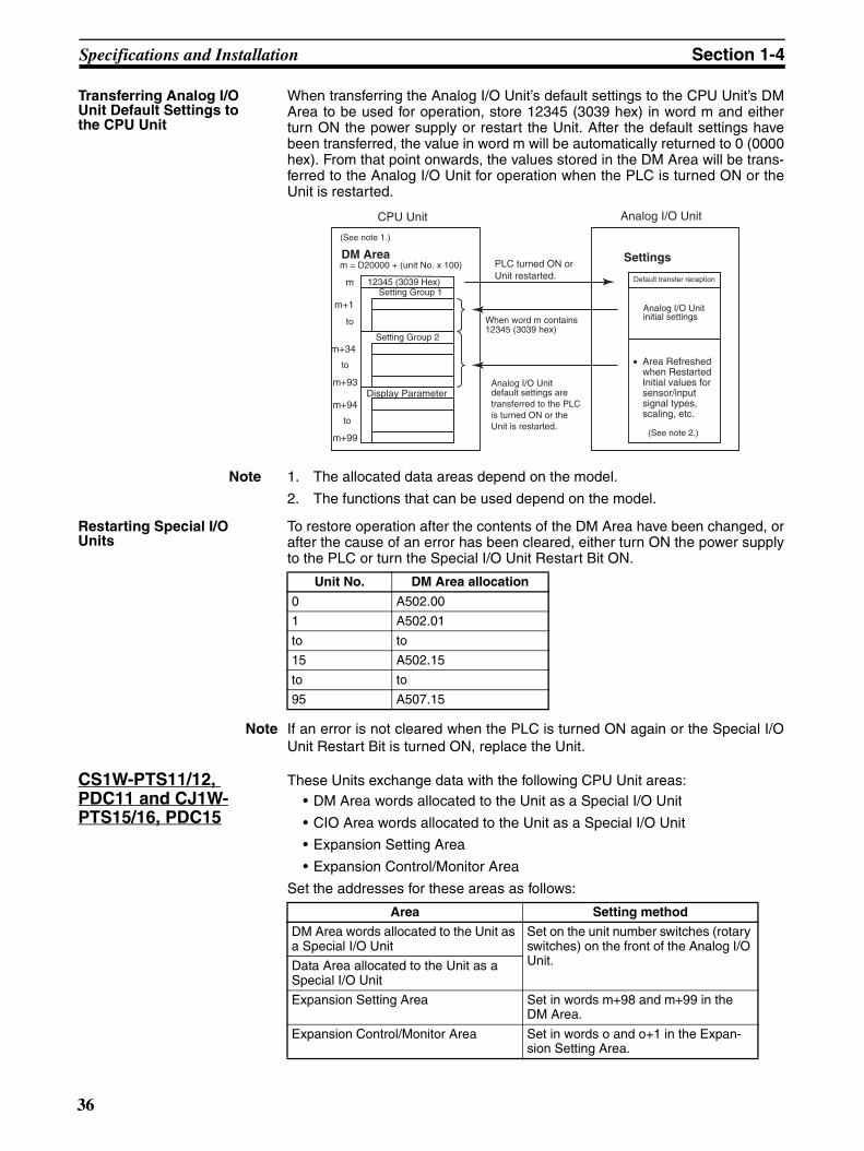
Specifications and Installation Section 1-4
Transferring Analog I/O Unit Default Settings to the CPU Unit
When transferring the Analog I/O Unit’s default settings to the CPU Unit’s DMArea to be used for operation, store 12345 (3039 hex) in word m and eitherturn ON the power supply or restart the Unit. After the default settings havebeen transferred, the value in word m will be automatically returned to 0 (0000hex). From that point onwards, the values stored in the DM Area will be trans-ferred to the Analog I/O Unit for operation when the PLC is turned ON or theUnit is restarted.
Note 1. The allocated data areas depend on the model.
2. The functions that can be used depend on the model.
Restarting Special I/O Units
To restore operation after the contents of the DM Area have been changed, orafter the cause of an error has been cleared, either turn ON the power supplyto the PLC or turn the Special I/O Unit Restart Bit ON.
Note If an error is not cleared when the PLC is turned ON again or the Special I/OUnit Restart Bit is turned ON, replace the Unit.
CS1W-PTS11/12, PDC11 and CJ1W-PTS15/16, PDC15
These Units exchange data with the following CPU Unit areas: • DM Area words allocated to the Unit as a Special I/O Unit
• CIO Area words allocated to the Unit as a Special I/O Unit
• Expansion Setting Area
• Expansion Control/Monitor Area
Set the addresses for these areas as follows:
DM Aream = D20000 + (unit No. x 100)
Setting Group 1
Setting Group 2
When word m contains 12345 (3039 hex)
Settings
Default transfer reception
Analog I/O Unit initial settings
CPU Unit Analog I/O Unit
to
to
12345 (3039 Hex)m
m+1
• Area Refreshed when Restarted Initial values for sensor/input signal types, scaling, etc.
PLC turned ON orUnit restarted.
m+34
m+99
Display Parameterm+93
m+94
Analog I/O Unit default settings are transferred to the PLC is turned ON or theUnit is restarted.
to
(See note 1.)
(See note 2.)
Unit No. DM Area allocation
0 A502.00
1 A502.01
to to
15 A502.15
to to
95 A507.15
Area Setting method
DM Area words allocated to the Unit as a Special I/O Unit
Set on the unit number switches (rotary switches) on the front of the Analog I/O Unit.Data Area allocated to the Unit as a
Special I/O Unit
Expansion Setting Area Set in words m+98 and m+99 in the DM Area.
Expansion Control/Monitor Area Set in words o and o+1 in the Expan-sion Setting Area.
36

Specifications and Installation Section 1-4
Expansion Area addresses are determined as follows, according to the set-tings.
DM Area A total of 100 words beginning with first word, word m (m = D20000 + unitnumber (0 to 95) x 100).
Special I/O Unit Area A total of 10 words beginning with first word, word n (n = 2000 + unit number(0 to 95) x 100).
Expansion Setting Area A total of 46 words (See note.) beginning with first word, word o (o = Wordspecified in word m+99 in the area specified in word m+98 in the DM Area).
Note The expansion setting area for a CJ-series PLC is 24 words from word o toword o+23.
Expansion Control/Monitor Area
A total of 35 words beginning with first word, word p. (p = address specified inword o+1 in the area specified in word o in the Expansion Setting Area.
CPU Unit Analog I/O Unit
• Special I/O Unit Area
nn+1
n+9
• DM Area
m
m+98m+99
Default block read command
Setting Group 1
Setting Group 2
• Unit SettingsInitial setting transfer direction reception
• Continuously Refreshed Area Alarm settings, zero/span adjustment settings, etc.
• Area Refreshed at Restart
Initial values for sensor types, scaling, etc.
I/O refresh
Power ON or Unit restarted.
Power ON or Unit restarted.
I/O refresh, power ON, or Unit restarted.
(See note.)
(See note.)
• Data for Operation
• Expansion Setting Area
oo+1o+2
o+45
Setting Group 3
• Settings
• Restart Refresh Area Zero/span adjustment set-tings, operation count set-tings, top/valley hold set-tings, and number of in-puts setting
• Data for Operation• Expansion Control/ Monitor Area
pp+1
p+34
p = Address specified in o +1 in area specified in o of Expansion Setting Area
n = 2000 + (unit No. × 10)
• Process values, analog output values, rates of change, error flags
• Operation count, hold function controls, hold values, etc.
o = Address specified in m +99 in area specified in m+98 of DM Area
Area of Expansion Control/Monitor Area
First word in Expansion Control/Monitor Area
Area of Expansion Setting Area
First Word in Expansion Setting Area
m+34
m+97
Display Parameterm+93
m+94
I/O refresh
Power ON or Unit restarted.
(See note.)
to
to
to
to
to
to
m = D20000 + (unit No. × 100)
Expansion Setting Area Allocation Settings
Expansion Control/Monitor Area Settings
Expansion Setting Area Allocation Settings
m+2
Points Usedm+1
Power ON or Unit restarted.
(See note.)
Power ON or Unit restarted.
(See note.)
37

Specifications and Installation Section 1-4
Note 1. This applies when word m contains other than 12345 (3039 hex), e.g.,0000 hex. When word m contains 12345 (3039 hex), the transfer directionwill be reversed.
2. The expansion setting area for a CJ-series PLC is 24 words from word oto word o+23.
3. When specifying an expansion control/monitor area or an expansion set-ting area, be sure that it does not overlap with other areas that are beingused. If areas overlap, the words that are allocated may be overwritten, re-sulting in unexpected operation.
4. When specifying the first word in an expansion control/monitor area or anexpansion setting area, be sure that the end of the memory area is not ex-ceeded.
These areas have the following functions for Analog I/O Units.
DM Area Data is set in this area. The allocated portion of the DM Area is divided into the five areas shown below.
Note For details, refer to the explanations for the individual Units.
1) Default block read command:
When the PLC is turned ON or the Unit is restarted, the data in the Analog I/O Unit can be transferred back to the CPU Unit.
Beginning word m contains fixed. When word m contains 12345 (3039 hex), then the data is transferred from the Analog I/O Unit to the CPU Unit.
When word m contains less than 12345 (3039 hex), such as 0 (0000 hex), then data is transferred from the CPU Unit to the Analog I/O Unit as usual.
2) Setting Group 1 (continuously refreshed area):While the PLC is ON (even if the CPU Unit is operating), this area is continuously refreshed.This area is refreshed when the PLC is turned ON or the Unit is restarted.
The area is refreshed regardless of the CPU Unit’s opera-tion mode (i.e., RUN, Monitor, or Program Mode).Alarm settings, zero/span adjustment values, and so on, are set here.
3) Setting Group 2 (initial settings area):
Data is transferred once to this area from the CPU Unit when the PLC is turned ON or the Unit is restarted, unless word m contains 12345.
Sensor types, process value scaling, alarm supplemen-tary functions, etc., are set here.
4) Display parameters:
Data range error addresses are stored here. (See note.)
5) Expansion Setting Area settings:
Data is transferred once to this area from the CPU Unit when the PLC is turned ON or the Unit is restarted, as long as word m contains other than 12345.
Expansion Setting Area settings are made here.
Special I/O Unit Area The data in for operation is continuously refreshed.The following types of data are transferred from Analog I/O Units to the CPU Unit: Values scaled in industrial units for pro-cess values and rate-of-change values; alarm contact data, Input Disconnection Flag data, etc.
38

Specifications and Installation Section 1-4
Note The ERC indicator on the Unit’s front panel will light if an out-of-range settingis made in either Setting Group 1 or 2. The offset from word m to the first wordcontaining the out-of-range error will be stored as the Data Range ErrorAddress in the DM Area in four digits hexadecimal. If the first word containingthe out-of-range error is in the Expansion Setting Area, the Data Range ErrorAddress offset will be 100 words or more (e.g., 100 words for an error in thefirst word in the Expansion Setting Area). When an error is made in SettingGroup 1, the ERR indicator will light and the data range error address will bestored immediately. When an error is made in Setting Group 2, the ERC indi-cator will light when the PLC is turned ON again or the Unit is restarted andthe data range error address will be stored at that time.
Transferring Analog I/O Unit Default Settings to the CPU Unit
When transferring the Analog I/O Unit’s default settings to the CPU Unit’s DMArea and Expansion Setting Area used for operation, store 12345 (3039 hex)in word m and either turn the power supply OFF and ON or restart the Unit.After the default settings have been transferred, the value in word m will beautomatically returned to 0 (0000 hex). From that point onwards, the valuesstored in the DM Area will be transferred to the Analog I/O Unit for operationwhen the PLC is turned ON or when the Unit is restarted.
Expansion Setting Area
Data for operation is continuously refreshed.Note For details, refer to the explanations for the individual Units.
3) Setting Group 3 (initial settings area):Data is transferred once to this area from the CPU Unit when the PLC is turned ON or the Unit is restarted, as long as word m contains other than 12345 and the Expansion Setting Area settings are allocated (i.e., word m+98 contains other than 0).
Expansion Control/Monitor Area settings, zero/span adjustment supplementary function, and so on, are set here.
Expansion Con-trol/Monitor Area
Data for operation is continuously refreshed. Bits for begin-ning or resetting the hold function selection, adjustment period control, control bits, and so on, are transferred from the CPU Unit to the Analog Input Unit. Adjustment period notices, peak and bottom values, top and valley values, and so on, are transferred from the Analog Input Unit to the CPU Unit.
CPU Unit Analog I/O Unit
DM Area
m
m+1
m+98m+99
Setting Group 1
Setting Group 2
Unit Settings
Analog I/O Unit initial settings
• Area Refreshed when Restarted Initial values for sensor types, scaling, etc.
m = D20000 + (unit No. x 100)
m+34
m+97
Display Parametersm+93
m+94
Expansion Setting Area settings
12345 (3039 hex)
Area for Expansion Memory AreaFirst word in Expansion Setting Area
Power ON or Unit restarted.
When word m contains 12345 (3039 hex)
When the PLC is turned ON or the Unit is restarted, the default values in the Unit are sent to the CPU Unit.
to
to
to
Default transfer reception
Expansion Setting Area settings
39
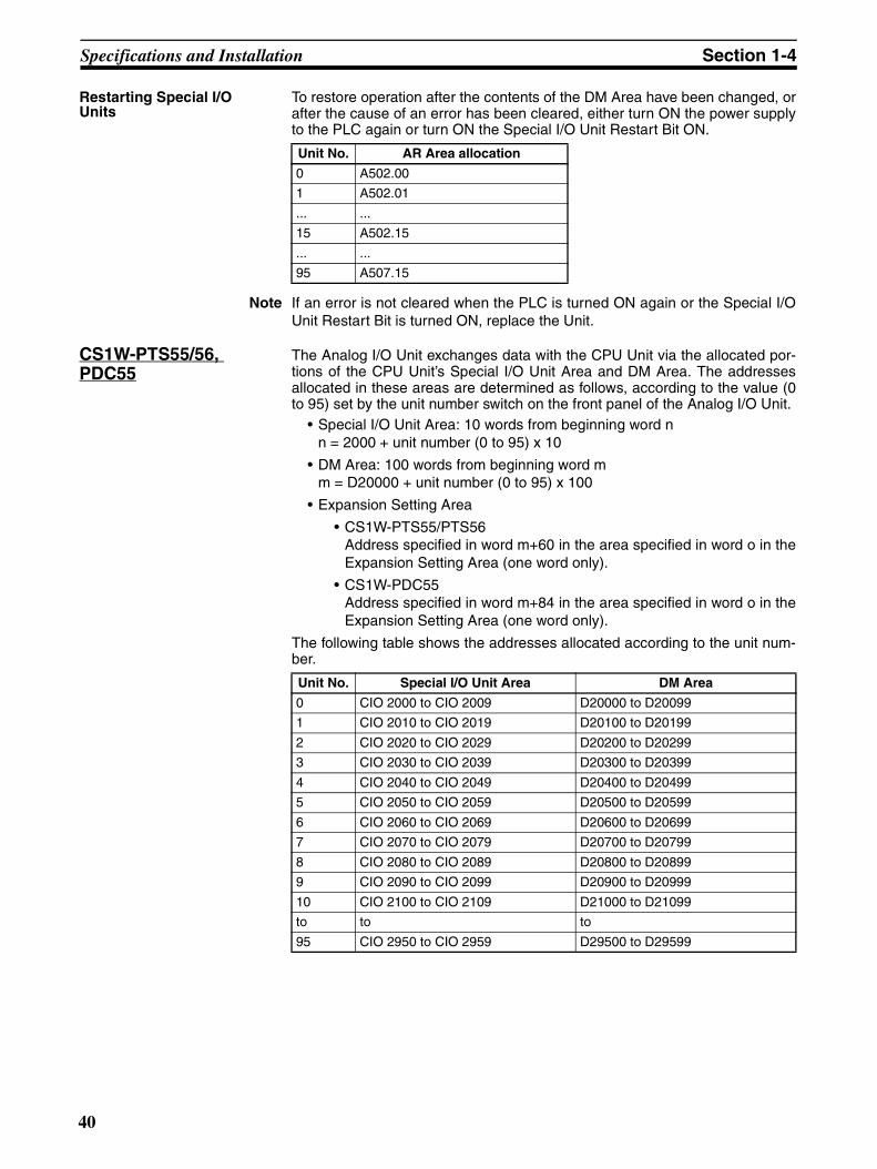
Specifications and Installation Section 1-4
Restarting Special I/O Units
To restore operation after the contents of the DM Area have been changed, orafter the cause of an error has been cleared, either turn ON the power supplyto the PLC again or turn ON the Special I/O Unit Restart Bit ON.
Note If an error is not cleared when the PLC is turned ON again or the Special I/OUnit Restart Bit is turned ON, replace the Unit.
CS1W-PTS55/56, PDC55
The Analog I/O Unit exchanges data with the CPU Unit via the allocated por-tions of the CPU Unit’s Special I/O Unit Area and DM Area. The addressesallocated in these areas are determined as follows, according to the value (0to 95) set by the unit number switch on the front panel of the Analog I/O Unit.
• Special I/O Unit Area: 10 words from beginning word nn = 2000 + unit number (0 to 95) x 10
• DM Area: 100 words from beginning word mm = D20000 + unit number (0 to 95) x 100
• Expansion Setting Area
• CS1W-PTS55/PTS56Address specified in word m+60 in the area specified in word o in theExpansion Setting Area (one word only).
• CS1W-PDC55Address specified in word m+84 in the area specified in word o in theExpansion Setting Area (one word only).
The following table shows the addresses allocated according to the unit num-ber.
Unit No. AR Area allocation
0 A502.00
1 A502.01
... ...
15 A502.15
... ...
95 A507.15
Unit No. Special I/O Unit Area DM Area
0 CIO 2000 to CIO 2009 D20000 to D20099
1 CIO 2010 to CIO 2019 D20100 to D20199
2 CIO 2020 to CIO 2029 D20200 to D20299
3 CIO 2030 to CIO 2039 D20300 to D20399
4 CIO 2040 to CIO 2049 D20400 to D20499
5 CIO 2050 to CIO 2059 D20500 to D20599
6 CIO 2060 to CIO 2069 D20600 to D20699
7 CIO 2070 to CIO 2079 D20700 to D20799
8 CIO 2080 to CIO 2089 D20800 to D20899
9 CIO 2090 to CIO 2099 D20900 to D20999
10 CIO 2100 to CIO 2109 D21000 to D21099
to to to
95 CIO 2950 to CIO 2959 D29500 to D29599
40
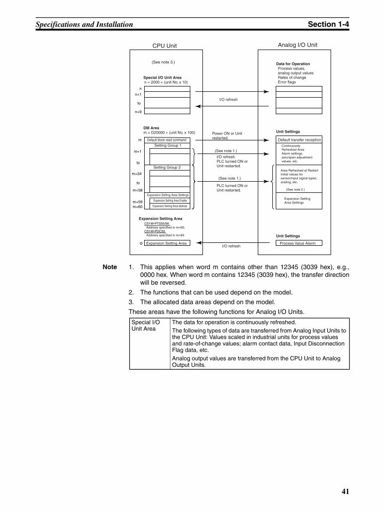
Specifications and Installation Section 1-4
Note 1. This applies when word m contains other than 12345 (3039 hex), e.g.,0000 hex. When word m contains 12345 (3039 hex), the transfer directionwill be reversed.
2. The functions that can be used depend on the model.
3. The allocated data areas depend on the model.
These areas have the following functions for Analog I/O Units.
n
n+1
n+9
m
m+1
m+34
Expansion Setting Area Settingsm+58
m+59Expansion Setting Area addressm+60
Expansion Setting AreaCS1W-PTS55/56
Address specified in m+60.CS1W-PDC55
Address specified in m+84
Expansion Setting Areao Process Value Alarm
Expansion Setting Area Settings
CPU Unit Analog I/O Unit
DM Aream = D20000 + (unit No. x 100)
Default block read commandSetting Group 1
Setting Group 2
I/O refresh
Power ON or Unit restarted.
Data for OperationProcess values, analog output valuesRates of changeError flags
Unit Settings
Default transfer reception
I/O refreshPLC turned ON or Unit restarted.
(See note 1.)
PLC turned ON or Unit restarted.
(See note 1.)
(See note 2.)
(See note 3.)
Special I/O Unit Arean = 2000 + (unit No. x 10)
I/O refresh
Unit Settings
Continuously Refreshed AreaAlarm settings, zero/span adjustment values, etc.
Area Refreshed at RestartInitial values for sensor/input signal types, scaling, etc.
to
to
to
Expansion Setting Area Enable
Special I/O Unit Area
The data for operation is continuously refreshed.The following types of data are transferred from Analog Input Units to the CPU Unit: Values scaled in industrial units for process values and rate-of-change values; alarm contact data, Input Disconnection Flag data, etc.Analog output values are transferred from the CPU Unit to Analog Output Units.
41
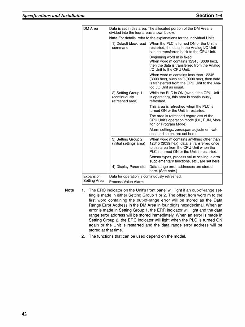
Specifications and Installation Section 1-4
Note 1. The ERC indicator on the Unit's front panel will light if an out-of-range set-ting is made in either Setting Group 1 or 2. The offset from word m to thefirst word containing the out-of-range error will be stored as the DataRange Error Address in the DM Area in four digits hexadecimal. When anerror is made in Setting Group 1, the ERR indicator will light and the datarange error address will be stored immediately. When an error is made inSetting Group 2, the ERC indicator will light when the PLC is turned ONagain or the Unit is restarted and the data range error address will bestored at that time.
2. The functions that can be used depend on the model.
DM Area Data is set in this area. The allocated portion of the DM Area is divided into the four areas shown below.Note For details, refer to the explanations for the individual Units.
1) Default block read command
When the PLC is turned ON or the Unit is restarted, the data in the Analog I/O Unit can be transferred back to the CPU Unit.
Beginning word m is fixed. When word m contains 12345 (3039 hex), then the data is transferred from the Analog I/O Unit to the CPU Unit.When word m contains less than 12345 (3039 hex), such as 0 (0000 hex), then data is transferred from the CPU Unit to the Ana-log I/O Unit as usual.
2) Setting Group 1 (continuously refreshed area)
While the PLC is ON (even if the CPU Unit is operating), this area is continuously refreshed.
This area is refreshed when the PLC is turned ON or the Unit is restarted.The area is refreshed regardless of the CPU Unit’s operation mode (i.e., RUN, Mon-itor, or Program Mode).Alarm settings, zero/span adjustment val-ues, and so on, are set here.
3) Setting Group 2 (initial settings area)
When word m contains anything other than 12345 (3039 hex), data is transferred once to this area from the CPU Unit when the PLC is turned ON or the Unit is restarted.Sensor types, process value scaling, alarm supplementary functions, etc., are set here.
4) Display Parameter Data range error addresses are stored here. (See note.)
Expansion Setting Area
Data for operation is continuously refreshed.
Process Value Alarm
42

Specifications and Installation Section 1-4
Transferring Analog I/O Unit Default Settings to the CPU Unit
When transferring the Analog I/O Unit’s default settings to the CPU Unit’s DMArea to be used for operation, store 12345 (3039 hex) in word m and eitherturn the power supply OFF and ON or restart the Unit. After the default set-tings have been transferred, the value in word m will be automatically returnedto 0 (0000 hex). From that point onwards, the values stored in the DM Areawill be transferred to the Analog I/O Unit for operation when the PLC is turnedON or the Unit is restarted.
Note 1. The allocated data areas depend on the model.
2. The functions that can be used depend on the model.
Restarting Special I/O Units
To restore operation after the contents of the DM Area have been changed, orafter the cause of an error has been cleared, either turn ON the power supplyto the PLC or turn ON the Special I/O Unit Restart Bit.
Note If an error is not cleared when the PLC is turned ON again or the Special I/OUnit Restart Bit is turned ON, replace the Unit.
CJ1W-PH41U These Units exchange data with the following areas in the CPU Unit:• DM Area words allocated to the Unit as a Special I/O Unit
• Special I/O Unit Area words in CIO Area
• Expansion Setting Area
• Expansion Control/Monitor Area
Set the addresses for these areas as follows:
12345 (3039 hex)
DM Aream = D20000 + (unit No. x 100)
When m contains 12345 (3039 Hex)
Settings
Default transfer reception
CPU Unit Analog I/O Unit
Area Refreshed when RestartedInitial values for sensor/input signal types, scaling, etc.
Power ON or Unitrestarted.
Analog I/O Unit default settings are transferred to the CPU Unit when the PLC is turned ON or the Unit is restarted.
(See note 1.)
(See note 2.)
Continuously Refreshed AreaAlarm settings, zero/span adjustment values, etc.
Expansion Setting Area Settings
Expansion Setting Area address
Expansion Setting Area Settings
Setting Group 1
Setting Group 2to
to
Expansion Setting Area Enable
m
m+1
m+98m+99
m+34
m+97
Display Parametersm+93
m+94
to Analog I/O Unit default settings are transferred to the CPU Unit when the PLC is turned ON or the Unit is restarted.
Unit No. DM Area allocation
0 A502.00
1 A502.01
to to
15 A502.15
to to
95 A507.15
Area Setting method
DM Area words allocated to the Unit as a Special I/O Unit
Set on the unit number switches (rotary switches) on the front of the Analog I/O Unit.Special I/O Unit Area words in CIO Area
43

Specifications and Installation Section 1-4
Allocated area addresses are determined as follows, according to the set-tings:
• DM Area: A total of 100 words beginning with first word, word m (m =D20000 + unit number (0 to 95) x 100).
• Special I/O Unit Area: A total of 10 words beginning with first word, word n(n = CIO 2000 + unit number (0 to 95) x 10).
• Expansion Setting Area: A total of 100 words beginning with first word,word o (o = Word specified in word m+99 in the area specified in wordm+98, m+98 and m+99 are in the DM Area).
• Expansion Control/Monitor Area: A total of 46 words beginning with firstword, word p (p = address specified in word o+33 in the area specified inword o+32, o+32 and o+33 are in the Expansion Setting Area).
Expansion Setting Area Set in words m+98 and m+99 in the DM Area.
Expansion Control/Monitor Area Set in words o+32 and o+33 in the Expansion Setting Area.
Area Setting method
44

Specifications and Installation Section 1-4
Note 1. This applies when word m contains other than 12345 (3039 hex), e.g.,0000 hex. When word m contains 12345 (3039 hex), the transfer directionwill be reversed.
2. When specifying the Expansion Control/Monitor Area or an ExpansionSetting Area, be sure that it does not overlap with other words that are be-ing used for another purpose. If areas overlap, the words that are allocatedmay be overwritten, resulting in unexpected operation.
3. When specifying the first word in the Expansion Control/Monitor Area orthe Expansion Setting Area, be sure that the end of the memory area is notexceeded.
nn+1
n+9
mm+1
m+2
m+98m+99
oo+1
o+32
pp+1
p+46
m+34
m+97
m+93
m+94
o+33
o+99
Special I/O Unit Arean = CIO 2000 + unit No. x 10
CPU Unit Analog I/O Unit
I/O refresh
I/O refresh
Power ON or Unit restarted.
I/O refresh, power ON,or Unit restarted.
Power ON or Unit restarted.
Power ON or Unit restarted.
I/O refresh, power ON,or Unit restarted.
Power ON or Unit restarted.
Power ON or Unit restarted.
Data for Operation Process value, alarm contact data, etc.
Data for Operation Hold function settings,rate-of-change values, hold values, etc.
Settings
Initial setting transfer direction reception
Settings
DM Aream = D20000 + unit No. x 100
Default block read command
Operation settingsSetting group 1
Setting group 2
Display parameters
Expansion Setting Area allocations
Area of Expansion Setting Area
First word of Expansion Setting Area
Setting group 3
Setting group 4Area of Expansion Control/Monitor Area
to
to
to
to
to
(See note 1.)
(See note 1.)
(See note 1.)
(See note 1.)
(See note 1.)
(See note 1.)
(See note 1.)
Expansion Setting Area o = Word specified in m+99 in area specified in m+98 in DM Area
Expansion Control/Monitor Areap = Address specified in o+33 in area specified in o+32 in Expansion Setting Area
Power ON or Unit restarted.
• Restart Refresh Area Rate-of-change function, zero/span adjustment supplementary function, etc.
First word of Expansion Control/Monitor Area
• Continuously Refresh-ed Area Alarm settings, zero/span adjustment settings, etc.
• Area Refreshed at Restart Initial values for input type, scaling, etc.
Expansion Setting Area Allocation Settings
• Continuously Refreshed Area Rate of change, etc.
Expansion Control/Mon-itor Area Settings
45

Specifications and Installation Section 1-4
These areas have the following functions for Analog I/O Units.
DM Area Data is set in this area. The allocated portion of the DM Area is divided into the five areas shown below.
Note: For details, refer to the explanations for the individual Units.
1. Default block read command
When the power is turned ON or the Unit is restarted, the default data in the Analog I/O Unit can be read to the CPU Unit.• Beginning word m is fixed.• When word m contains 12345
(3039 hex), then the data is transferred from the Analog I/O Unit to the CPU Unit.
• When word m contains other than 12345 (3039 hex), e.g., 0 (0000 hex), then data is transferred from the CPU Unit to the Analog I/O Unit as usual.
2. Setting Group 1 (continuously re-freshed area)
While the PLC is ON (even if the CPU Unit is operating), this area is continu-ously refreshed. This area is also refreshed when the power is turned ON or the Unit is restarted. The area is refreshed regardless of the CPU Unit's operation mode (i.e., RUN, Monitor, or Program Mode). Alarm settings, zero/span adjustment values, etc., are set here.
3. Setting Group 2 (initial settings area)
When word m contains anything other than 12345 (3039 hex), data is transferred once to the Analog I/O Unit from the CPU Unit when the power is turned ON or the Unit is restarted. Input types, process value scaling, alarm supplementary func-tions, etc., are set here.
4. Display Parame-ter
Data range error addresses are stored here. (See note.)
5. Expansion Set-ting Area set-tings
Data is transferred once to the Analog I/O Unit from the CPU Unit when the power is turned ON or the Unit is restarted, as long as word m contains other than 12345. Expansion Setting Area settings are made here.
CIO Area The data for operation is continuously refreshed. The following types of data are transferred from the Analog I/O Unit to the CPU Unit: Val-ues scaled in industrial units for the process value, alarm contact data, Input Error Flag data, etc.
46

Specifications and Installation Section 1-4
Note The ERC indicator on the Unit's front panel will light if an out-of-range settingis made in either Setting Group 1 (continuously refreshed area) or SettingGroup 2 (initial settings area). The offset from word m to the first word contain-ing the out-of-range error will be stored as the Data Range Error Address inthe DM Area in four digits hexadecimal. If the first word containing the out-of-range error is in the Expansion Setting Area, the Data Range Error Addressoffset will be 100 words or more (e.g., 100 words for an error in the first wordin the Expansion Setting Area).When an error is made in Setting Group 1, the ERC indicator will light and thedata range error address will be displayed immediately. When an error ismade in Setting Group 2, the ERC indicator will light when the power is turnedON again or the Unit is restarted and the data range error address will be dis-played at that time. For details, refer to 1-6 Error Processing.
Transferring Analog I/O Unit Initial Settings to the CPU Unit
When transferring the Analog I/O Unit initial settings to the CPU Unit DM Areaand Expansion Setting Area for operation, store 12345 (3039 hex) in word mand either again turn ON the power supply or restart the Unit. After the defaultsettings have been transferred, the value in word m will be automaticallyreturned to 0 (0000 hex). From that point onwards, the values stored in theDM Area will be transferred to the Analog I/O Unit for operation when thepower is turned ON or the Unit is restarted.The Analog I/O Unit holds the default settings, and they cannot be overwritten.
Expansion Setting Area
Data is set in this area.Note: For details, refer to the explanations for the individual Units.
1. Setting Group 3 (continuously re-freshed area)
While the PLC is ON (even if the CPU Unit is operating), this area is continu-ously refreshed. This area is also refreshed when the power is turned ON or the Unit is restarted. The area is refreshed regardless of the CPU Unit's operation mode (i.e., RUN, Monitor, or Program Mode). Settings, such the as rate-of-change alarm setting, are set here.
2. Setting Group 4 (initial settings area)
Data is transferred once to the Analog I/O Unit from the CPU Unit when the power is turned ON or the Unit is restarted, as long as word m contains other than 12345 and the Expansion Setting Area settings are allocated (i.e., word m+98 contains other than 0). Expansion Control/Monitor Area settings, rate-of-change function, zero/span adjustment supplementary function, etc., are set here.
Expansion Control/Moni-tor Area
Data for operation is continuously refreshed. Bits for beginning or resetting the hold function selection, adjustment period control, con-trol bits, etc., are transferred from the CPU Unit to the Analog I/O Unit. Adjustment period notice, peak and bottom values, top and val-ley values, and so on, are transferred from the Analog I/O Unit to the CPU Unit.
47

Specifications and Installation Section 1-4
Restarting Special I/O Units
To restart Unit operation after the contents of the DM Area have beenchanged, or after the cause of an error has been cleared, either turn ON thepower supply to the PLC again or turn ON the Special I/O Unit Restart Bit.
Note If an error is not cleared when the power is turned ON again or the Special I/OUnit Restart Bit is turned ON, replace the Analog I/O Unit.
1-4-4 Mounting the Units
CS Series Use the following procedure to mount the CS-Series Analog I/O Unit to theBackplane.
1,2,3... 1. Mount the Unit to the Backplane by attaching it with the top and bottomhooks.
2. Properly insert each Unit into the Backplane connector, and tighten thescrews on the bottom of the Unit to a torque of 0.4 N·m.
m
m+1
m+98m+99
m+34
m+97
m+93
m+94
Power ON or Unit restarted.
Word m = 12345 (3039 hex)
to
to
to
Settings
Initial setting transfer direction reception
DM Aream = D20000 + unit No. x 100
12345 (3028 hex)Setting group 1
Setting group 2
Display parameters
Expansion Setting Area allocations
Area of Expansion Setting Area
First word of Expansion Setting Area
CPU Unit Analog I/O Unit
Power ON or Unit re-started:Initial settings in Analog I/O Unit are transferred to CPU Unit.
Initial settings in Analog I/O Unit
• Area Refreshed at Restart
Initial values for in-put type, scaling, etc.
Expansion Setting Area Allocation Settings
Unit No. Restart Bit
0 A502.00
1 A502.01
to to
15 A502.15
to to
95 A507.15
Hook
Backplane
48

Specifications and Installation Section 1-4
3. To remove a Unit, loosen the screws and lift it off.
Note To allow for mounting and removal of Units, leave at least 20 mm of spacebetween Units, as shown in the following diagram.
CJ Series Use the following procedure to connect Analog I/O Units to a CJ-series Rack.
1,2,3... 1. Align the connectors and press in firmly on the Units to connect them com-pletely.
2. Move the sliders on the top and bottom of the Unit to the lock position tosecure the Units. The sliders should click into place.
Screw
20 mm min.
20 mm min.
Phillips-head screwdriver
Backplane
HooksConnector
Hook holes
49

Specifications and Installation Section 1-4
3. Attach an End Cover to the Unit on the right end of the Rack.
Note The CJ-series PLC may not operate properly if the sliders are not lockedfirmly into place.
1-4-5 Precautions when Handling Units
CS Series Turn OFF the power to the PLC before mounting or removing Units, or con-necting or disconnecting wiring.To prevent adverse effects from noise, place I/O wiring in separate ducts fromhigh-voltage or power lines.Always ground the GR terminal on the Power Supply Unit of the PLC.When wiring, leave the label on the Unit’s top panel in place to prevent foreignobjects such as wire clippings from dropping into the Unit. The label must beremoved after wiring or the Unit will overheat.
CJ Series Be sure to turn OFF the power supply to the PLC before installing or discon-necting Units or connecting lines.To reduce the risk of malfunctioning due to electrical noise, wire input and out-put lines in separate ducts from high-voltage and power lines.When wiring a Unit, place a label over the top of the Unit to prevent wire clip-pings or other materials from getting inside the Unit. When the wiring hasbeen completed, the label must be removed to prevent heat radiation.
Lock
Slider
Release
Move the sliders to the backuntil they click into place.
Remove the label after wiring has been completed.
50

Specifications and Installation Section 1-4
Precautions in Handling Removable Terminal Blocks
• The terminal block is removable. Press the lever on the bottom of the ter-minal block to remove the terminal block.
• During normal use, check that the lever is raised and the terminal block islocked in place.
Note Precautions for Terminal Blocks on Thermocouple Input Units and CJ1W-PH41U Isolated-type Universal Input Units
• Thermocouple Input Units and CJ1W-PH41U Isolated-type UniversalInput Units have cold junction compensators. The specified accuracy willbe as specified only when the cold junction compensator (i.e., the termi-nal block) and the Unit are used as a set. Always use the terminal blockand the Unit as a set. Both the CJ1W-PTS51 Unit terminal block and thisUnit have labels on them providing the serial number.
• If repairs are required to the Unit, always return the terminal block (includ-ing the cold junction compensator) with the Unit.
MACH
No.
x101
x100
RUNERCERH
Remove the label after thewiring has been completed.
B1A1
MACH
No.
X101
X100
RUNERCERH
MACH
No.X100FEDCBA98765432
10FEDCBA98765432
10X101
RUNERC
ERH
Serial No.LOT No.
23X3SER No.
00088188E
51
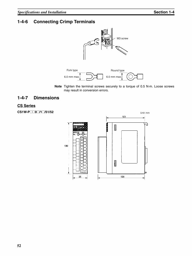
Specifications and Installation Section 1-4
1-4-6 Connecting Crimp Terminals
Note Tighten the terminal screws securely to a torque of 0.5 N·m. Loose screwsmay result in conversion errors.
1-4-7 Dimensions
CS Series
CS1W-P@@0@/1@/51/52
M3 screw
Fork type Round type
6.0 mm max. 6.0 mm max.
Unit: mm
52
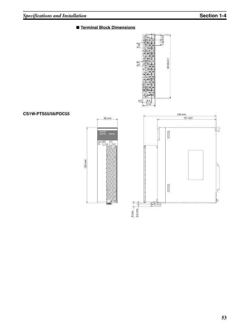
Specifications and Installation Section 1-4
Terminal Block Dimensions
CS1W-PTS55/56/PDC55
4.5 8.417.8
92.6
6±0.
1
7.62
8.23
7.62
6.4
101 mm
125 mm
35 mm
130
mm
2.4
mm
6 m
m
MACHNo. X101
RUNERC ERH
X100
53

Specifications and Installation Section 1-4
Terminal Block Dimensions
CJ Series
6.4
7.6
296.4
7
10
18.6
89
65
31
2.7
902.
7
MACHNo.
×101
×100
PTS51
B1 A1
RUNERCERH
54

Operating Procedures Section 1-5
1-5 Operating ProceduresUse the following procedures to operate the Analog I/O Unit. The proceduresare the same for all models.
Initial Setup (Hardware)
1,2,3... 1. Set the unit number, using the rotary switches on the front panel of theUnit.
2. Mount the Unit to either a CPU Rack or Expansion Rack. A maximum of 80 Units for the CS Series and 40 Units for the CJ Seriescan be mounted in a basic System (with no restrictions on mounting loca-tion).
3. Connect sensors or external control units.
4. Connect a Programming Device to the PLC.
5. Turn ON the power to the PLC.
6. Create the I/O tables.
7. Allow time for warmup (see note).
Note Analog I/O Units require time to warm up after the PLC is turned ON.Warmup times differ for each Unit, as shown in the following table.
Initial Software Setup
1,2,3... 1. Make the initial settings in the DM Area (m to m+99).
• When using the Unit’s default values, set word m to 12345 (3039 hex).
• When using data from the CPU Unit’s DM Area, set word m to a valueother than 12345 (3039 hex), such as 0000 hex.
2. Turn the power OFF and then back ON again, or turn ON the Special I/OUnit Restart Bit.
Model Warmup time
CS1W-PTS01-V1/11, CJ1W-PTS15 45 min
CS1W-PTS5@, CJ1W-PTS5@ 30 min
CJ1W-PH41U Resistance thermometer inputs: 30 minThermocouple, ±100-mV user-set range inputs: 45 minCurrent and voltage inputs (not including ±100-mV user-set range inputs): 30 minPotentiometer inputs: 10 min
Other Analog I/O Units 10 min
55

Operating Procedures Section 1-5
Ladder Diagram Program
Name Model Basic ladder diagram programming
Isolated-type Thermo-couple Input Unit
CS1W-PTS01-V1
Note: Bit 00 of word n +9 (CIO 2009.00 for unit number 00) is the Sensor Error Flag for CS1W-PTS5@ and CJ1W-PTS5@.
CS1W-PTS11/51
CS1W-PTS55
CJ1W-PTS51/ 15
Isolated-type Resis-tance Thermometer Input Unit (Pt100, JPt100)
CS1W-PTS02
Isolated-type Resis-tance Thermometer Input Unit (Ni508.4)
CS1W-PTS03
Isolated-type Resis-tance Thermometer Input Unit (Pt100, JPt100, Pt50, Ni508.4)
CS1W-PTS12CJ1W-PTS16
Isolated-type Resis-tance Thermometer Input Unit (Pt100, JPt100)
CS1W-PTS52
CS1W-PTS56
CJ1W-PTS52
Isolated-type 2-Wire Transmitter Input Unit
CS1W-PTW01
Note: Bit 00 of word n +9 (CIO 2009.00 for unit number 00) is the Sensor Error Flag for CS1W-PDC5@.
Isolated-type Direct Current Input Unit
CS1W-PDC01
CS1W-PDC11CJ1W-PDC15
CS1W-PDC55
Power Transducer Input Unit
CS1W-PTR01 Reading the converted value using MOV(021).
Isolated-type Pulse Input Unit
CS1W-PPS01
Analog Input Unit (100 mW)
CS1W-PTR02
Isolated-type Analog Output Unit
CS1W-PMV01 Writing the value to convert using MOV(021). After writing, then checking of the answer input value and output disconnection.
CS1W-PMV02 Writing the value to convert using MOV(021).
Isolated-type Univer-sal Input Unit
CJ1W-PH41U
Reading the converted value using MOV(021) with the Input Disconnection Flag's NC condition as the input condition.
Input Disconnection Flag (See note.)
Bit 08 of word n+92009.08
Input No. 1 converted valueWord n+1
MOV (021)
2001
D01000
Reading the converted value using MOV(021) with the Input Error Flag's NC condition as the input condition.
Input Error Flag (See note)
Input No. 1 converted valueWord n+1
Bit 08 of word n+92009.08
MOV (021)
2001
D01000
Reading the converted value using MOVL(498) with the Input Error Flag's NC condition as the input condition.
Input Error Flag
Input No. 1 converted valueWord n
Bit 08 of word n+92009.08
MOVL (498)
2000
D01000
56

Error Processing Section 1-6
1-6 Error ProcessingThe following table shows the contents of the LED indicator displays on thefront panel of the Analog I/O Unit. The contents shown here are the same forall models. For error processing specific to each Unit, refer to the explanationsfor the individual Units.
Errors Detected by the Analog I/O Unit
Note 1. The following table shows the processing and results for Setting Group 1.
ERC LED (red)
RUN LED (green)
Contents Probable cause Unit operation Remedy
Lit Lit Setting Group 1 (con-tinuously refreshed area) error (See note 1.)
The Analog I/O Unit started up and was operating properly, but an out-of-range setting was made in Setting Group 1 in the DM Area.
The Unit continues operating with the Setting Group 1 data prior to the change.
Restore the set value to within the allowable range. (There is no need to turn the power supply OFF and ON or to restart the Unit.)
Not lit Setting Group 1 (See note 1.), Setting Group 2 (See note 2.) error, or Expansion Setting Area (See note 3.)
An out-of-range set-ting was made for either Setting Group 1 or Setting Group 2 in the DM Area.
The Unit will not start up.
Restore the set value to within the allowable range, and then either turn the power sup-ply OFF and ON or restart the Unit.
Processing Result LED indicators on Unit
Data range error address stored in
DM Area
When an out-of-range setting is made in Setting Group 1 during operation
The Unit continues to operate with the Setting Group 1 data prior to the change.
ERC indicator is lit. RUN indicator remains lit.
The lowest DM address where the out-of-range error occurred is stored, in four digits hexa-decimal, as the off-set value from m (i.e., the number of added words).
↓When the setting is changed within the allowable range during operation
The Unit operates with the Setting Group 1 data after the change.
ERC indicator is not lit. RUN indicator remains lit.
If there is no other error, 0000 hex is stored. (If there is another error, the offset value for that DM address is stored.)
When the PLC is turned ON or the Unit is restarted with an error still in effect.
The Unit will not start up.
ERC indicator is lit. RUN indicator is not lit.
The lowest DM address where the out-of-range error occurred is stored, in four digits hexa-decimal, as the off-set value from m (i.e., the number of added words).
↓When the setting is made within the allowable range, and the PLC is turned ON or the Unit is restarted
The Unit starts up normally.
ERC indicator is not lit. RUN indicator is lit.
If there is no other error, 0000 hex is stored. (If there is another error, the offset value for that DM address is stored.)
57

Error Processing Section 1-6
2. The following table shows the processing and results for Setting Group 2.
Processing Result LED indicators on Unit
Data range error address stored in
DM Area
When an out-of-range setting is made in Setting Group 2 during operation
The Unit operates with the Setting Group 2 data prior to the change.
ERC indicator is not lit. RUN indicator remains lit.
If there is no other setting error, 0000 hex remains stored. (If there is another setting error, the offset value for that DM address is stored.)
↓When the PLC is turned ON or when the Unit is restarted
The Unit will not start up.
ERC indicator is lit. RUN indicator is not lit.
The lowest DM address where the out-of-range error occurred is stored, in four digits hexa-decimal, as the off-set value from m (i.e., the number of added words).
↓When the setting is made within the allowable range, and the PLC is turned ON or the Unit is restarted
The Unit starts up normally.
ERC indicator is not lit. RUN indicator is lit.
If there is no other error, 0000 hex is stored. (If there is another error, the offset value for that DM address is stored.)
58
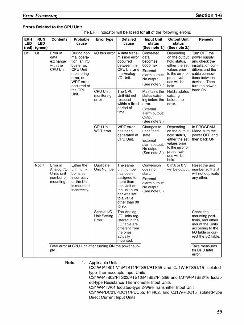
Error Processing Section 1-6
Errors Related to the CPU UnitThe ERH indicator will be lit red for all of the following errors.
Note 1. Applicable Units: CS1W-PTS01-V1/PTS11/PTS51/PTS55 and CJ1W-PTS51/15 Isolated-type Thermocouple Input UnitsCS1W-PTS02/PTS03/PTS12/PTS52/PTS56 and CJ1W-PTS52/16 Isolat-ed-type Resistance Thermometer Input UnitsCS1W-PTW01 Isolated-type 2-Wire Transmitter Input UnitCS1W-PDC01/PDC11/PDC55, PTR02, and CJ1W-PDC15 Isolated-typeDirect Current Input Units
ERH LED (red)
RUN LED
(green)
Contents Probable cause
Error type Detailed cause
Input Unit status
(See note 1.)
Output Unit status
(See note 2.)
Remedy
Lit Lit Error in data exchange with the CPU Unit
During nor-mal opera-tion, an I/O bus error, CPU Unit monitoring error, or WDT error occurred at the CPU Unit.
I/O bus error A data trans-mission error occurred between the CPU Unit and the Analog I/O Unit.
Converted data becomes 0000 hex.External alarm output: No output.(See note 3.)
Depending on the output hold status, either the set values prior to the error or preset val-ues will be held.
Turn OFF the power supply and check the installation con-ditions and the cable connec-tions between devices. Then turn the power back ON.CPU Unit
monitoring error
The CPU Unit did not respond within a fixed period of time.
Maintains the status exist-ing before the error. External alarm output: Output. (See note 3.)
Held at status existing before the error.
CPU Unit WDT error
WDT error has been generated at CPU Unit.
Changes to undefined state.
External alarm output: No output. (See note 3.)
Depending on the output hold status, either the set values prior to the error or preset val-ues will be held.
In PROGRAM Mode, turn the power OFF and then back ON.
Not lit Error in Analog I/O Unit’s unit number or mounting
Either the unit num-ber is set incorrectly or the Unit is mounted incorrectly.
Duplicate Unit Number
The same unit number has been assigned to more than one Unit or the unit num-ber was set to a value other than 00 to 95.
Conversion does not start.External alarm output: No output. (See note 3.)
0 mA or 0 V will be output.
Reset the unit number so that it will not duplicate any other.
Special I/O Unit Setting Error
The Analog I/O Units reg-istered in the I/O table are different from the ones actually mounted.
Check the mounting posi-tions, and either mount the Units according to the I/O table or cor-rect the I/O table.
Fatal error at CPU Unit after turning ON the power sup-ply
Take measures for CPU fatal error.
59

Error Processing Section 1-6
CS1W-PTR01 Power Transducer Input UnitCS1W-PTR02 Analog Input Unit (100 mV)CS1W-PPS01 Isolated-type Pulse Input Unit.CJ1W-PH41U Isolated-type Universal Input Units
2. Applicable Unit: CS1W-PMV01 Isolated-type Analog Output Unit.
3. Indicates the external alarm output status for CS1W-PTS51/PTS52 andCJ1W-PTS51/PTS52. The alarm outputs will operate normally even if allloads are turned OFF from the CPU Unit.
4. If either of the following changes is made for the Expansion Setting Areafor the CJ1W-PTS15/-PTS16/-PDC15/-AD04U/-PH41U, the previous datawill be left in the Expansion Setting Area even after the change has beenmade.Clear the previous data when changing either of these settings.
• The Expansion Setting Area allocation is disabled.
• The Expansion Setting Area Address setting is changed while the Ex-pansion Setting Area allocation is enabled.
60

Specification Changes Section 1-7
1-7 Specification Changes
1-7-1 CS1W-PTS01-V1, CS1W-PTS02/PTS03, CS1W-PTW01, CS1W-PDC01, CS1W-PPS01, and CS1W-PMV01
The specifications of the following I/O Units with the lot number 000426 XXXXor later (manufactured since April 26, 2000) have been changed as shown inthe table below.
Overview
Details
Improvement in Rate-of-change Calculation Method
Before Change
The current process value was compared with the value before the time set bythe comparison time interval and the difference between them was divided bythe comparison time interval to find the rate-of-change per second. When thedifference was small, the calculated value turned out to be so small that it washard to identify the change.
Name Model Main changes
Isolated-type Thermocouple Input Unit CS1W-PTS01-V1 • Improved effective resolution: From the equivalent of 10 bits to 1/4,096
• Improved rate-of-change calculation: Refer to Improvement in Rate-of-change Calculation Method below for details.
Isolated-type Resistance Thermometer Input Unit
CS1W-PTS02 • Improved effective resolution: From the equivalent of 10 bits to 1/4,096
• Improved rate-of-change calculation: Refer to Improvement in Rate-of-change Calculation Method below for details.
Isolated-type Resistance Thermometer Input Unit (Ni508.4 Ω)
CS1W-PTS03 • Improved effective resolution: From the equivalent of 11 bits to 1/4,096
• Improved rate-of-change calculation: Refer to Improvement in Rate-of-change Calculation Method below for details.
Isolated-type 2-Wire Transmitter Input Unit CS1W-PTW01 • Improved effective resolution: From the equivalent of 10 bits to 1/4,096
• Improved rate-of-change calculation: Refer to Improvement in Rate-of-change Calculation Method below for details.
• Reduced 26-V consumption current: 0.4 A to 0.16 A
Isolated-type Direct Current Input Unit CS1W-PDC01 • Improved effective resolution: From the equivalent of 10 bits to 1/4,096
• Improved rate-of-change calculation: Refer to Improvement in Rate-of-change Calculation Method below for details.
• Added input range: 0 to 20 mA (Refer to New Input Range (0 to 20 mA) for the CS1W-PDC01 for details.)
Isolated-type Pulse Input Unit CS1W-PPS01 • Changed instantaneous value setting method and added time unit setting function (Refer to Instanta-neous Value Measurement and Measurement Time Unit Setting for CS1W-PPS01 for details.)
• Reduction of 26 V consumption current: 0.22 A to 0.16 A
Isolated-type Analog Output Unit CS1W-PMV01 • Improved resolution (answer back input): From the equivalent of 9 bits to 1/2000
61

Specification Changes Section 1-7
After Change
The current process value is compared with the value before the time set bythe comparison time interval and the difference is output. When the differenceis small, the comparison time interval can be set longer so that the changecan be easily identified.
New Input Range (0 to 20 mA) for the CS1W-PDC01
Before Change
–10 to 10 V, 0 to 10 V, –5 to 5 V, 0 to 5 V, 1 to 5 V, 4 to 20 mA, user-set volt-ages
After Change
–10 to 10 V, 0 to 10 V, –5 to 5 V, 0 to 5 V, 1 to 5 V, 4 to 20 mA, user-set volt-ages, 0 to 20 mA (new)The settings are shown below. (There is no need to change the setting unlessthe new setting is going to be used.)
• Before Change (m = D20000 + Unit number x 100)
• After Change (m = D20000 + Unit number x 100)
Instantaneous Value Measurement and Measurement Time Unit Setting for CS1W-PPS01
Instantaneous Value Measurement
Before Change
The number of pulses per second was output as an instantaneous value. Tocalculate the value, the number of pulses per 0.1 second was multiplied by 10.For pulses less than 10 Hz, 10 pulses/second and 0 pulses/second werealternately output due to inaccurate calculations.
After Change
The number of pulses per second is counted for that one second and outputas is. This allows calculation of pulses down to 1 Hz.
Offset Setting range
Setting name
Input No. 1
Input No. 2
Input No. 3
Input No. 4
m+34 m+48 m+62 m+76 0 to 6 Input signal
0: –10 to +10 V, 1: 0 to 10 V, 2: –5 to 5 V, 3: 0 to 5 V, 4: 1 to 5 V, 5: 4 to 20 mA, 6: User-set voltages
Offset Setting range
Setting name
Input No. 1
Input No. 2
Input No. 3
Input No. 4
m+34 m+48 m+62 m+76 0 to 7 Input signal0: –10 to +10 V, 1: 0 to 10 V, 2: –5 to 5 V, 3: 0 to 5 V, 4: 1 to 5 V, 5: 4 to 20 mA, 6: User-set voltages7: 0 to 20 mA
62

Specification Changes Section 1-7
Measurement Time Unit Setting
This new function allows setting of measurement time unit to enable measur-ing pulses with much slower frequencies. Measurement time unit can be setto 1, 3, 10, 30, or 60 s. The settings are shown below. (There is no need to change the setting if thecurrent unit of 1 s is going to be used.)
• Before Change (m = D20000 + Unit number x 100)
• After Change (m = D20000 + Unit number x 100)
1-7-2 CS1W-PTS51/PTS52 and CJ1W-PTS51/PTS52The specifications of the following I/O Units with the lot number XX84 or later(manufactured since August 2004) have been changed as shown in the tablebelow.
CS1W-PTS51/PTS52 • Before Change (m = D20000 + Unit number × 100)
Offset Setting range
Setting name
Input No. 1
Input No. 2
Input No. 3
Input No. 4
m+30 m+38 m+46 m+54 Bits 00 to 03: 0 to 3
Decimal point position from right of instanta-neous value conversion coefficient
Bits 04 to 15: 0
Not used
Offset Setting range
Setting name
Input No. 1
Input No. 2
Input No. 3
Input No. 4
m+30 m+38 m+46 m+54 Bits 00 to 03: 0 to 3
Decimal point from right of instantaneous value conversion coefficient
Bits 04 to 07: 0 to 4
Instantaneous value time unit0: 1 s1: 3 s2: 10 s3: 30 s4: 60 s
Bits 08 to 15: 0
Not used
Model Name Main changes
CS1W-PTS51/PTS52
Isolated-type Thermocouple Input Units
• Added setting for selecting the span adjustment resolution for the zero/span adjustment func-tion.Before change: Resolution of 1/1,000After change: Resolution of 1/1,000 or 1/10,000 selectable
CJ1W-PTS51/PTS52
DM address Data range Default value Data name
Input No. 1 Input No. 2 Input No. 3 Input No. 4 Decimal Hexadecimal
Span adjust-ment
m+4 m+8 m+12 m+16 0 to 9999 0000 to 270F hex
1000 (03E8 hex) Set value × 0.001
63

Specification Changes Section 1-7
• After Change (m = D20000 + Unit number × 100)
Note Indicates the value after transferring the default values (set when 12345 iswritten to word m).
CJ1W-PTS51/PTS52 Settings are the same as for the CS1 models, except that the address m+35becomes m+32.
1-7-3 CS1W-PTS55 and CS1W-PDC55The specifications of the following Analog I/O Units with a lot number of070315_XXXX or later (manufactured since March 15, 2007) have beenchanged as shown in the table below.
CS1W-PTS55 • Before Change (m = D20000 + Unit number × 100)
DM address Data range Default value Data name
Input No. 1 Input No. 2 Input No. 3 Input No. 4 Decimal Hexadecimal
Span adjust-ment
m+4 m+8 m+12 m+16 0 to 9999 0000 to 270F hex
1000 (03E8 hex) m+35 contains 0:Set value × 0.001
0 to 32000 0000 to 7D00 hex
10000 (2710 hex)
m+35 contains 1: Set value × 0.0001
Span adjust-ment mode setting
m+35 0, 1 0000, 0001 hex 1 (See note.) 0: 1/1,0001: 1/10,000
Model Name Main changes
CS1W-PTS55 Isolated-type Thermocouple Input Unit
Added functionality for tempera-ture data notation in units of 0.1°C or 0.1°F. (Only binary is supported for the data format.)
CJ1W-PDC55 Isolated-type Thermocouple Input Unit
Added functionality for holding data during a sensor error.
Word Bit Default value Description Settings
m+34 00 0 Temperature unit setting 0: °C 1: °F
04 0 Data format 0: Binary (Negative values are given as 2’s complements.)1: BCD
08 0 Minus sign display format for BCD display
0: “F” used to indicate the minus sign.1: Leftmost bit used to indicate the minus sign. The setting is disabled if bits 04 to 07 are set to 0.
12 0 Data direction at sensor error 0: Goes to upper limit at sensor error.1: Goes to lower limit at sensor error.
64

Specification Changes Section 1-7
• After Change (m = D20000 + Unit number × 100)
CS1W-PDC55 • Before Change (m = D20000 + Unit number × 100)
• After Change (m = D20000 + Unit number × 100)
Word Bit Default value Description Settings
m+34 00 0 Temperature unit setting 0: °C 1: °F
01 0 Data unit setting 0: Follow the input type setting.1: Use units of 0.1°C or 0.1°F as the temperature data format. (Only binary is supported.)
04 0 Data format 0: Binary (Negative values are given as 2’s complements.)
1: BCD
08 0 Minus sign display format for BCD display
0: “F” used to indicate the minus sign.1: Leftmost bit used to indicate the minus sign. The setting is disabled if bits 04 to 07 are set to 0.
12 0 Data direction at sensor error 0: Goes to upper limit at sensor error.
1: Goes to lower limit at sensor error.
Word Bit Default value Description Settings
m+34 00 0 Data format 0: Binary (Negative values are given as 2’s complements.)
1: BCD
08 0 Minus sign display format for BCD display
0: “F” used to indicate the minus sign.1: Leftmost bit used to indicate the minus sign. The setting is disabled if bits 04 to 07 are set to 0.
12 0 Data direction at sensor error 0: Goes to upper limit at sensor error.1: Goes to lower limit at sensor error.
Word Bit Default value Description Settings
m+34 00 0 Data format 0: Binary (Negative values are given as 2’s complements.)1: BCD
08 0 Minus sign display format for BCD display
0: “F” used to indicate the minus sign.1: Leftmost bit used to indicate the minus sign. The setting is disabled if bits 04 to 07 are set to 0.
12 0 Data direction at sensor error 0: Goes to upper limit at sensor error.1: Goes to lower limit at sensor error.
13 0 Data held at sensor error 0: Follow the setting of bit 12.1: If there is a sensor error when the upper limit is exceeded, hold the data at the upper limit. If there is a sensor error when the lower limit is exceeded, hold the data at the lower limit.
65

Specification Changes Section 1-7
66

SECTION 2Individual Unit Descriptions for CS Series
This section describes each of the CS-series Analog I/O Units in detail.
2-1 CS1W-PTS01-V1 Isolated-type Thermocouple Input Unit . . . . . . . . . . . . . . . . . . . . . . . . . . . . . . . . . . . 68
2-2 CS1W-PTS11 Isolated-type Thermocouple Input Unit . . . . . . . . . . . . . . . . . . . . . . . . . . . . . . . . . . . . . . 80
2-3 CS1W-PTS51 Isolated-type Thermocouple Input Unit . . . . . . . . . . . . . . . . . . . . . . . . . . . . . . . . . . . . . . 97
2-4 CS1W-PTS55 Isolated-type Thermocouple Input Unit . . . . . . . . . . . . . . . . . . . . . . . . . . . . . . . . . . . . . . 109
2-5 CS1W-PTS02 Isolated-type Resistance Thermometer Input Unit (Pt100 or JPt100) . . . . . . . . . . . . . . . 121
2-6 CS1W-PTS03 Isolated-type Resistance Thermometer Input Unit (Ni508.4) . . . . . . . . . . . . . . . . . . . . . 132
2-7 CS1W-PTS12 Isolated-type Resistance Thermometer Input Unit (Pt100, JPt100, Pt50, Ni508.4) . . . . 142
2-8 CS1W-PTS52 Isolated-type Resistance Thermometer Input Unit (Pt100, JPt100). . . . . . . . . . . . . . . . . 157
2-9 CS1W-PTS56 Isolated-type Resistance Thermometer Input Unit (Pt100, JPt100). . . . . . . . . . . . . . . . . 167
2-10 CS1W-PTW01 2-Wire Transmitter Input Unit . . . . . . . . . . . . . . . . . . . . . . . . . . . . . . . . . . . . . . . . . . . . 177
2-11 CS1W-PDC01 Isolated-type Direct Current Input Unit . . . . . . . . . . . . . . . . . . . . . . . . . . . . . . . . . . . . . 189
2-12 CS1W-PDC11 Isolated-type Direct Current Input Unit . . . . . . . . . . . . . . . . . . . . . . . . . . . . . . . . . . . . . 200
2-13 CS1W-PDC55 Isolated-type Direct Current Input Unit . . . . . . . . . . . . . . . . . . . . . . . . . . . . . . . . . . . . . 218
2-14 CS1W-PTR01 Power Transducer Input Unit . . . . . . . . . . . . . . . . . . . . . . . . . . . . . . . . . . . . . . . . . . . . . . 229
2-15 CS1W-PTR02 Analog Input Unit (100 mV) . . . . . . . . . . . . . . . . . . . . . . . . . . . . . . . . . . . . . . . . . . . . . . 238
2-16 CS1W-PPS01 Isolated-type Pulse Input Unit . . . . . . . . . . . . . . . . . . . . . . . . . . . . . . . . . . . . . . . . . . . . . 247
2-17 CS1W-PMV01 Isolated-type Analog Output Unit . . . . . . . . . . . . . . . . . . . . . . . . . . . . . . . . . . . . . . . . . 258
2-18 CS1W-PMV02 Isolated-type Analog Output Unit . . . . . . . . . . . . . . . . . . . . . . . . . . . . . . . . . . . . . . . . . 267
67
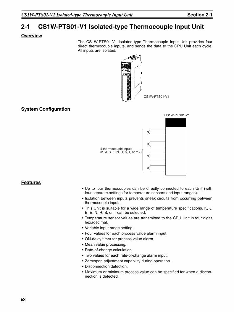
CS1W-PTS01-V1 Isolated-type Thermocouple Input Unit Section 2-1
2-1 CS1W-PTS01-V1 Isolated-type Thermocouple Input UnitOverview
The CS1W-PTS01-V1 Isolated-type Thermocouple Input Unit provides fourdirect thermocouple inputs, and sends the data to the CPU Unit each cycle.All inputs are isolated.
System Configuration
Features• Up to four thermocouples can be directly connected to each Unit (with
four separate settings for temperature sensors and input ranges).• Isolation between inputs prevents sneak circuits from occurring between
thermocouple inputs.• This Unit is suitable for a wide range of temperature specifications. K, J,
B, E, N, R, S, or T can be selected.• Temperature sensor values are transmitted to the CPU Unit in four digits
hexadecimal.• Variable input range setting.• Four values for each process value alarm input.• ON-delay timer for process value alarm.• Mean value processing.• Rate-of-change calculation.• Two values for each rate-of-change alarm input.• Zero/span adjustment capability during operation.• Disconnection detection.• Maximum or minimum process value can be specified for when a discon-
nection is detected.
CS1W-PTS01-V1
4 thermocouple inputs (K, J, B, E, N, R, S, T, or mV)
CS1W-PTS01-V1
68
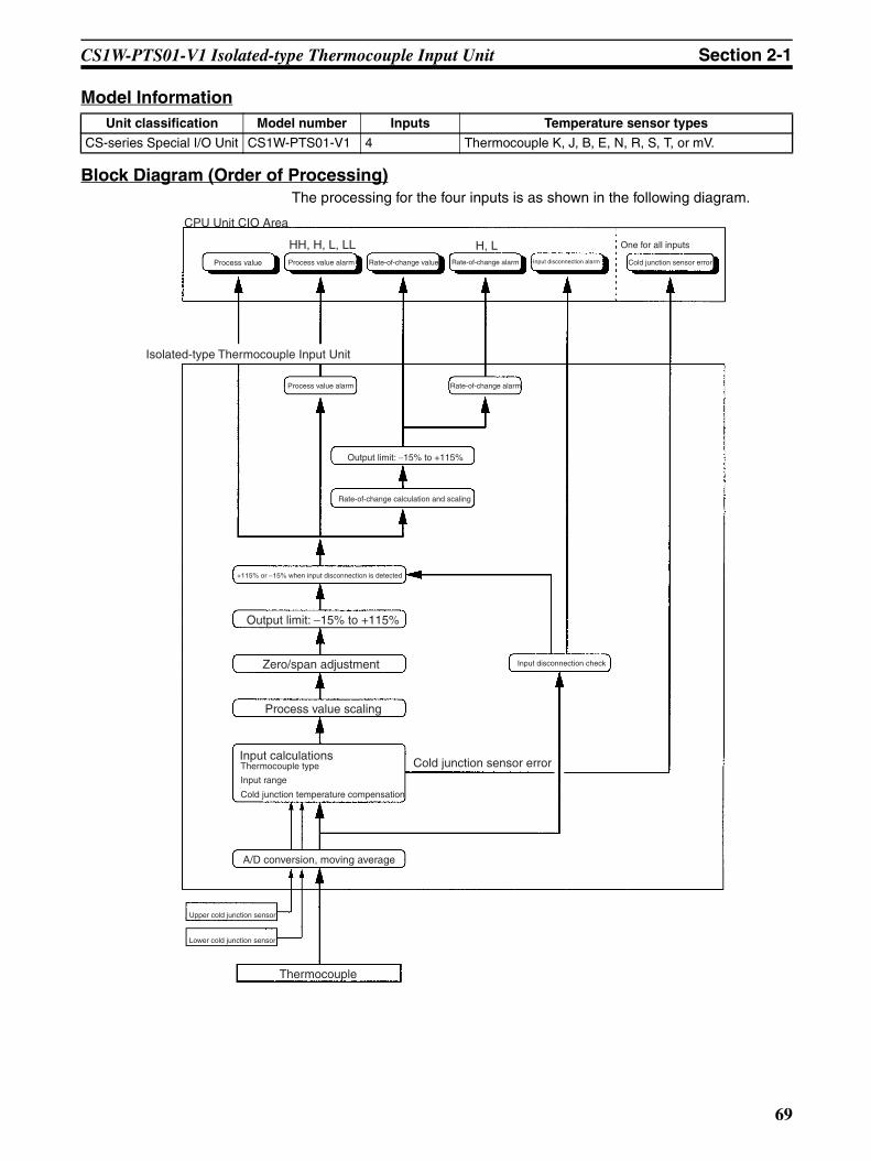
CS1W-PTS01-V1 Isolated-type Thermocouple Input Unit Section 2-1
Model Information
Block Diagram (Order of Processing)The processing for the four inputs is as shown in the following diagram.
Unit classification Model number Inputs Temperature sensor types
CS-series Special I/O Unit CS1W-PTS01-V1 4 Thermocouple K, J, B, E, N, R, S, T, or mV.
CPU Unit CIO Area
Process value Process value alarm Rate-of-change value Rate-of-change alarm Input disconnection alarm Cold junction sensor error
One for all inputs
Isolated-type Thermocouple Input Unit
Process value alarm Rate-of-change alarm
Output limit: −15% to +115%
Rate-of-change calculation and scaling
+115% or −15% when input disconnection is detected
Output limit: −15% to +115%
Zero/span adjustment
Process value scaling
Input calculationsThermocouple type
Input range
Cold junction temperature compensation
A/D conversion, moving average
Upper cold junction sensor
Lower cold junction sensor
Thermocouple
Input disconnection check
Cold junction sensor error
HH, H, L, LL H, L
69

CS1W-PTS01-V1 Isolated-type Thermocouple Input Unit Section 2-1
SpecificationsItem Specifications
Model number CS1W-PTS01-V1
Applicable PLC CS Series
Unit classification CS-series Special I/O Unit
Mounting position CS-series CPU Rack or CS-series Expansion Rack (Cannot be mounted to C200H Expansion I/O Rack or SYSMAC BUS Remote I/O Slave Rack.)
Maximum number of Units 80 (within the allowable current consumption and power consumption range)
Unit numbers 00 to 95 (Cannot duplicate Special I/O Unit numbers.)
Areas for data exchange with CPU Unit
Special I/O Unit Area
10 words/Unit
Thermocouple Input Unit to CPU Unit:All process values, process value alarms (LL, L, H, HH), rate-of-change values, rate-of-change alarms (L, H), disconnection alarms, cold junction sensor errors
DM Area words allocated to Spe-cial I/O Units
100 words/UnitCPU Unit to Thermocouple Input Unit:Temperature sensor type, input range (user set), scaling of process value data to be stored in allocated words in CIO area, number of items for moving average, process value alarm setting (LL, L, H, HH), rate-of-change alarm setting (L, H), zero/span adjustment value, etc.
Number of temperature sensor inputs
4
Temperature sensor types Thermocouple B, E, J, K, N, R, S, T or –80 to 80 mV. (Set separately for each of four inputs.)
Sensor type, input range, and scaling to industrial units are separate for each of the 4 inputs.Note Sensor type, input range, and scal-
ing to industrial units are set in the DM Area.
Input ranges The input range can be set within any of the measurable input ranges shown in Table 1 (below).Note Internally, inputs are processed in
five ranges (refer to Table 2 below), so accuracy and resolution accord with these internal ranges.
Example:Thermocouple: K; input range: 0 to 500°C; industrial unit scaling: 0 to 500°C. DM Area settings are as follows:
Thermocouple: 3 (0003 hex)Input signal maximum: 5000 (1388 hex)Input signal minimum: 0 (0000 hex)Industrial unit maximum value stored: 500 (01F4 hex)Industrial unit minimum value stored: 0 (0000 hex)
Scaling in industrial units Data to be stored in the allocated words in the CIO area must be scaled (with the minimum and maximum values set). Data can be stored at 0% to 100%.
Data storage in the CIO Area The value derived from carrying out the following processing in order of the actual pro-cess data in the input range is stored in four digits hexadecimal (binary values) in the allocated words in the CIO Area.1) Mean value processing → 2) Scaling → 3) Zero/span adjustment → 4) Output limits
Accuracy (25°C) ±0.1% (of internal range full span)As shown in the following equation, the accuracy depends on the ratio of the selected internal range (0 to 4) span to the set input range span.
Temperature coefficient ±0.015% /°C, for any of internal range numbers 0 to 4.
Resolution 1/4,096 (of internal range full span)As shown in the following equation, the resolution depends on the ratio of the selected internal range (0 to 4) span to the set input range span.
Cold junction compensation error ±1°C, at 20 ±10°CWarmup time 45 min
Maximum signal input –80 to 80 mV
Accuracy = ±0.1% x Internal range span (electromotive force conversion)
Set input range span (electromotive force conversion)
Resolution =1
4096
Internal range span (electromotive force conversion)
Set input range span (electromotive force conversion)x
70

CS1W-PTS01-V1 Isolated-type Thermocouple Input Unit Section 2-1
Input impedance 20 kΩ min.
Input disconnection detection cur-rent
0.1 µA (typical)
Response time 1 s (travel time from input 0% to 90%, for step input)
Conversion period 150 ms/4 inputs
Maximum time to store data in CPU Unit
Conversion period + one CPU Unit cycle
Disconnection detection Detects disconnections at each input and turns ON the Disconnection Detection Flag.
Hardware detection time: Approx. 5 sThe process value overrange direction for when a disconnection occurs can be speci-fied. (High: 115% of set input range; low: –15% of set input range)
Function Mean value pro-cessing (input fil-ter)
Calculates the moving average for the specified number of process values (1 to 16), and stores that value in the CIO Area as the process value.
Process value alarm
Process value 4-point alarm (HH, H, LL, L), alarm hysteresis, and ON-delay timer (0 to 60 s) are available.
Rate-of-change calculation
Calculates the amount of change per comparison time interval (1 to 16 s).
Rate-of-change alarm
Rate-of-change 2-point alarm (H, L), alarm hysteresis (shared with process value alarm), and ON-delay timer (0 to 60 s, shared with process value alarm) are available.
Isolation Between temperature inputs and between input terminals and PLC signals: Isolation by transformer
Insulation resistance 20 MΩ (at 500 V DC) between inputs
Dielectric strength Between inputs: 1,000 V AC, at 50/60 Hz, for 1 min, leakage current 10 mA max.
External connections Terminal block (detachable)
Unit number settings Set by rotary switches on front panel, from 0 to 95.
Indicators Three LED indicators on front panel (for normal operation, errors detected at the Ther-mocouple Input Unit, and errors related to the CPU Unit).
Front panel connector Sensor input connector terminal block (detachable)
Effect on CPU Unit cycle time 0.3 ms
Current consumption 5 V DC at 150 mA max., 26 V DC at 150 mA max.
Dimensions 35 × 130 × 126 mm (W × H × D)Note The height including the Backplane is 145 mm.
Weight 450 g max.
Standard accessories Two cold junction sensors (installed in terminal block)
Item Specifications
71

CS1W-PTS01-V1 Isolated-type Thermocouple Input Unit Section 2-1
Sensor Types and Input RangesThe temperature sensor (thermocouple) type and input range are set in theallocated words in the DM Area for every four inputs. The input range can beset anywhere within the measurable input ranges shown in Table 1.
Table 1: Measurable Input Ranges
Note Set the input range in the DM Area within this range.
Inputs are processed internally in five progressive ranges (numbers 0 to 4), asshown in the following table.
Table 2: Internal Ranges
Therefore, the accuracy and resolution are determined by the ratio of theselected internal range (0 to 4) span to the set input range span (electromo-tive force converted value). For the internal range, a larger number is selectedwhen both the minimum and maximum values of the range fall within that nextrange.For example, suppose that the thermocouple type is K and the set input rangeis 0 to 800°C. The electromotive force for K 0 to 800°C is 0 to 33.277 mV.Since both the minimum and maximum values fall within the limits for internalrange No. 1 (–40 to 40 mV), that range will be selected.The following table shows the set input ranges corresponding to the internalrange numbers 0 to 4.
Table 3: Set Input Ranges Corresponding to Internal Ranges
Note With Thermocouple Input Units, process values can be scaled in industrialunits for the set input range. It is possible to set the process value scalinghigher than the resolution, but it will cause the values to be unstable.
Sensor type DM Area setting Measurable input range (See note.)
B 0 0 to 1,820°CE 1 –270 to 1,000°CJ 2 –210 to 1,200°CK 3 –270 to 1,372°CN 4 –270 to 1,300°CR 5 –50 to 1,768°CS 6 –50 to 1,768°CT 7 –270 to 400°CmV 8 –80 to 80 mV
Internal range number Thermocouple electromotive force
Internal range span
0 –80 to 80 mV 160 mV
1 –40 to 40 mV 80 mV
2 –20 to 20 mV 40 mV
3 –10 to 10 mV 20 mV
4 –5 to 5 mV 10 mV
Sensor type
Measurable Input range
Internal range No. 0
Internal range No. 1
Internal range No. 2
Internal range No. 3
Internal range No. 4
–80 to 80 mV –40 to 40 mV –20 to 20 mV –10 to 10 mV –5 to 5 mV
B 0 to 1,820°C Not used. Not used. 0 to 1,820°C 0 to 1,496°C 0 to 1,030°CE –270 to 1,000°C –270 to 1,000°C –270 to 537°C –270 to 286°C –270 to 153°C –94 to 80°CJ –210 to 1,200°C –210 to 1,200°C –210 to 713°C –210 to 366°C –210 to 186°C –100 to 95°CK –270 to 1,372°C –270 to 1,372°C –270 to 967°C –270 to 484°C –270 to 246°C –153 to 121°CN –270 to 1,300°C –270 to 1,300°C –270 to 1,097°C –270 to 584°C –270 to 318°C –270 to 171°CR –50 to 1,768°C Not used. –50 to 1,769°C –50 to 1,684°C –50 to 961°C –50 to 548°CS –50 to 1,768°C Not used. Not used. –50 to 1,769°C –50 to 1,035°C –50 to 576°CT –270 to 400°C Not used. –270 to 400°C –270 to 385°C –270 to 213°C –166 to 115°CmV –80 to 80 mV –80 to 80 mV –40 to 40 mV –20 to 20 mV –10 to 10 mV –5 to 5 mV
72
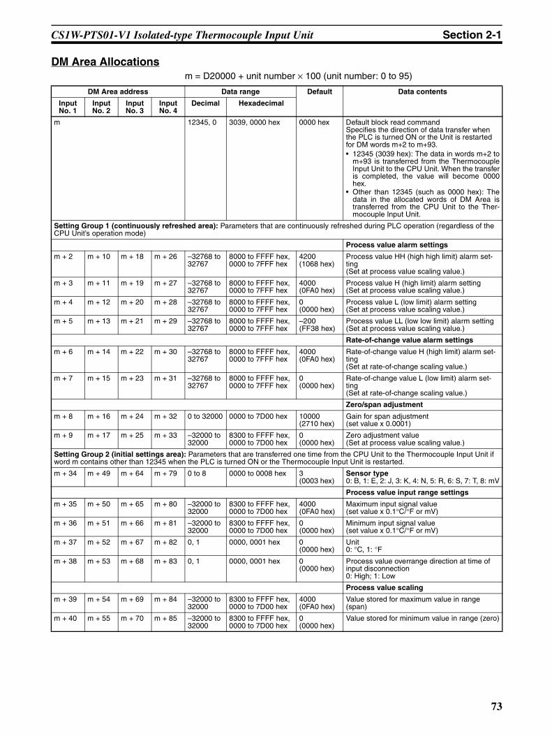
CS1W-PTS01-V1 Isolated-type Thermocouple Input Unit Section 2-1
DM Area Allocationsm = D20000 + unit number × 100 (unit number: 0 to 95)
DM Area address Data range Default Data contents
Input No. 1
Input No. 2
Input No. 3
Input No. 4
Decimal Hexadecimal
m 12345, 0 3039, 0000 hex 0000 hex Default block read commandSpecifies the direction of data transfer when the PLC is turned ON or the Unit is restarted for DM words m+2 to m+93.• 12345 (3039 hex): The data in words m+2 to
m+93 is transferred from the ThermocoupleInput Unit to the CPU Unit. When the transferis completed, the value will become 0000hex.
• Other than 12345 (such as 0000 hex): Thedata in the allocated words of DM Area istransferred from the CPU Unit to the Ther-mocouple Input Unit.
Setting Group 1 (continuously refreshed area): Parameters that are continuously refreshed during PLC operation (regardless of the CPU Unit’s operation mode)
Process value alarm settings
m + 2 m + 10 m + 18 m + 26 –32768 to 32767
8000 to FFFF hex, 0000 to 7FFF hex
4200 (1068 hex)
Process value HH (high high limit) alarm set-ting(Set at process value scaling value.)
m + 3 m + 11 m + 19 m + 27 –32768 to 32767
8000 to FFFF hex, 0000 to 7FFF hex
4000 (0FA0 hex)
Process value H (high limit) alarm setting(Set at process value scaling value.)
m + 4 m + 12 m + 20 m + 28 –32768 to 32767
8000 to FFFF hex, 0000 to 7FFF hex
0 (0000 hex)
Process value L (low limit) alarm setting(Set at process value scaling value.)
m + 5 m + 13 m + 21 m + 29 –32768 to 32767
8000 to FFFF hex, 0000 to 7FFF hex
–200 (FF38 hex)
Process value LL (low low limit) alarm setting(Set at process value scaling value.)
Rate-of-change value alarm settings
m + 6 m + 14 m + 22 m + 30 –32768 to 32767
8000 to FFFF hex, 0000 to 7FFF hex
4000 (0FA0 hex)
Rate-of-change value H (high limit) alarm set-ting(Set at rate-of-change scaling value.)
m + 7 m + 15 m + 23 m + 31 –32768 to 32767
8000 to FFFF hex, 0000 to 7FFF hex
0 (0000 hex)
Rate-of-change value L (low limit) alarm set-ting(Set at rate-of-change scaling value.)
Zero/span adjustment
m + 8 m + 16 m + 24 m + 32 0 to 32000 0000 to 7D00 hex 10000 (2710 hex)
Gain for span adjustment(set value x 0.0001)
m + 9 m + 17 m + 25 m + 33 –32000 to 32000
8300 to FFFF hex,0000 to 7D00 hex
0 (0000 hex)
Zero adjustment value(Set at process value scaling value.)
Setting Group 2 (initial settings area): Parameters that are transferred one time from the CPU Unit to the Thermocouple Input Unit if word m contains other than 12345 when the PLC is turned ON or the Thermocouple Input Unit is restarted.
m + 34 m + 49 m + 64 m + 79 0 to 8 0000 to 0008 hex 3 (0003 hex)
Sensor type0: B, 1: E, 2: J, 3: K, 4: N, 5: R, 6: S, 7: T, 8: mV
Process value input range settings
m + 35 m + 50 m + 65 m + 80 –32000 to 32000
8300 to FFFF hex, 0000 to 7D00 hex
4000 (0FA0 hex)
Maximum input signal value(set value x 0.1°C/°F or mV)
m + 36 m + 51 m + 66 m + 81 –32000 to 32000
8300 to FFFF hex, 0000 to 7D00 hex
0 (0000 hex)
Minimum input signal value(set value x 0.1°C/°F or mV)
m + 37 m + 52 m + 67 m + 82 0, 1 0000, 0001 hex 0 (0000 hex)
Unit0: °C, 1: °F
m + 38 m + 53 m + 68 m + 83 0, 1 0000, 0001 hex 0 (0000 hex)
Process value overrange direction at time of input disconnection0: High; 1: Low
Process value scaling
m + 39 m + 54 m + 69 m + 84 –32000 to 32000
8300 to FFFF hex, 0000 to 7D00 hex
4000 (0FA0 hex)
Value stored for maximum value in range (span)
m + 40 m + 55 m + 70 m + 85 –32000 to 32000
8300 to FFFF hex, 0000 to 7D00 hex
0 (0000 hex)
Value stored for minimum value in range (zero)
73

CS1W-PTS01-V1 Isolated-type Thermocouple Input Unit Section 2-1
Note The ERC indicator on the Unit’s front panel will light if an out-of-range settingis made in either Setting Group 1 or 2. The offset from word m to the first wordcontaining the out-of-range error will be stored as the Address of Data RangeError in the DM Area in four digits hexadecimal. For more information, refer to1-6 Error Processing.
Alarm supplementary functions
m + 41 m + 56 m + 71 m + 86 0 to 32000 0000 to 7D00 hex 40 (0028 hex)
Alarm hysteresis(Set at process value scaling value. Shared with process value alarm and rate-of-change alarm.)
m + 42 m + 57 m + 72 m + 87 0 to 60 0000 to 003C hex 0 (0000 hex)
Alarm ON-delay time (Unit: s)(Shared with process value alarm and rate-of-change alarm.)
Rate-of-change function
m + 43 m + 58 m + 73 m + 88 –32000 to 32000
8300 to FFFF hex, 0000 to 7D00 hex
4000 (0FA0 hex)
Rate-of-change range setting
Maximum rate-of-change value (Process value industrial unit; comparison time interval)
m + 44 m + 59 m + 74 m + 89 –32000 to 32000
8300 to FFFF hex, 0000 to 7D00 hex
–4000 (F060 hex)
Minimum rate-of-change value (Process value industrial unit; comparison time interval)
m + 45 m + 60 m + 75 m + 90 1 to 16 0001 to 0010 hex 1 (0001 hex)
Rate-of-change comparison time interval (Unit: s)
m + 46 m + 61 m + 76 m + 91 –32000 to 32000
8300 to FFFF hex, 0000 to 7D00 hex
4000 (0FA0 hex)
Rate-of-change value scaling
Value stored for maximum value in range
m + 47 m + 62 m + 77 m + 92 –32000 to 32000
8300 to FFFF hex, 0000 to 7D00 hex
0 (0000 hex)
Value stored for minimum value in range
Mean value processing function
m + 48 m + 63 m + 78 m + 93 1 to 16 0001 to 0010 hex 4 (0004 hex)
Number of process values for calculating mov-ing average for mean value processing
Storage parameter
m + 94 m + 95 m + 96 m + 97 0 to 93 0000 to 005D hex 0 (0000 hex)
Address of Data Range Error (See note.)
DM Area address Data range Default Data contents
Input No. 1
Input No. 2
Input No. 3
Input No. 4
Decimal Hexadecimal
74
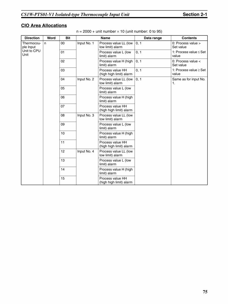
CS1W-PTS01-V1 Isolated-type Thermocouple Input Unit Section 2-1
CIO Area Allocationsn = 2000 + unit number × 10 (unit number: 0 to 95)
Direction Word Bit Name Data range Contents
Thermocou-ple Input Unit to CPU Unit
n 00 Input No. 1 Process value LL (low low limit) alarm
0, 1 0: Process value > Set value
1: Process value ≤ Set value
01 Process value L (low limit) alarm
0, 1
02 Process value H (high limit) alarm
0, 1 0: Process value < Set value1: Process value ≥ Set value
03 Process value HH (high high limit) alarm
0, 1
04 Input No. 2 Process value LL (low low limit) alarm
0, 1 Same as for input No. 1.
05 Process value L (low limit) alarm
06 Process value H (high limit) alarm
07 Process value HH (high high limit) alarm
08 Input No. 3 Process value LL (low low limit) alarm
09 Process value L (low limit) alarm
10 Process value H (high limit) alarm
11 Process value HH (high high limit) alarm
12 Input No. 4 Process value LL (low low limit) alarm
13 Process value L (low limit) alarm
14 Process value H (high limit) alarm
15 Process value HH (high high limit) alarm
75

CS1W-PTS01-V1 Isolated-type Thermocouple Input Unit Section 2-1
Thermocou-ple Input Unit to CPU Unit
n + 1 00 to 15 Input No. 1 process value –32768 to 32767 (8000 to FFFF hex, 0000 to 7FFF hex)
The present process value is stored according to the scal-ing set in the allocated words of the DM Area.
n + 2 00 to 15 Input No. 2 process value
n + 3 00 to 15 Input No. 3 process value
n + 4 00 to 15 Input No. 4 process value
n + 5 00 to 15 Input No. 1 rate-of-change value –32768 to 32767 (8000 to FFFF hex, 0000 to 7FFF hex)
The process value rate of change is stored according to the scaling set in the allocated words of the DM Area.
n + 6 00 to 15 Input No. 2 rate-of-change value
n + 7 00 to 15 Input No. 3 rate-of-change value
n + 8 00 to 15 Input No. 4 rate-of-change value
n + 9 00 Input No. 1 Rate-of-change value L (low limit) alarm
0, 1 0: Rate-of-change value > Set value1: Rate-of-change value ≤ Set value
01 Rate-of-change value H (high limit) alarm
0, 1 0: Rate-of-change value < Set value1: Rate-of-change value ≥ Set value
02 Input No. 2 Rate-of-change value L (low limit) alarm
0, 1 Same as for input No. 1.
03 Rate-of-change value H (high limit) alarm
04 Input No. 3 Rate-of-change value L (low limit) alarm
05 Rate-of-change value H (high limit) alarm
06 Input No. 4 Rate-of-change value L (low limit) alarm
07 Rate-of-change value H (high limit) alarm
08 Input No. 1 input disconnection 0, 1 0: Normal1: Disconnection
09 Input No. 2 input disconnection Same as for input No. 1.
10 Input No. 3 input disconnection Same as for input No. 1.
11 Input No. 4 input disconnection Same as for input No. 1.
12 Cold junction sensor error 0, 1 0: Normal1: Error
Direction Word Bit Name Data range Contents
76

CS1W-PTS01-V1 Isolated-type Thermocouple Input Unit Section 2-1
Terminal Connection Diagram
Note 1. Cold junction sensors are installed between A2 and A3, and between A8and A9 when the product is shipped. Do not remove them when using theUnit. If they are removed, temperatures cannot be measured correctly be-cause there will be no compensation.
2. Use the same cold junction sensors that come with the Unit, and leavethem just as they are. They are provided specifically for this Unit and its cir-cuitry, and temperatures cannot be measured correctly if they are switchedaround or if another Unit’s sensors are used in their place.
3. For unused input terminals, short-circuit the positive and negative sides(e.g., terminals A4 and B4 for input No. 1) of the thermocouple inputs withthe lead wire.
4. When connecting input No. 4, remove the cold junction sensor betweenCJ2+ and CJ2−, and then reconnect it after the input is connected. At-tempting to connect the input without removing the cold junction sensormay result in damage to the sensor.
N.C.N.C.N.C.
1+2+3+4+
N.C.N.C.N.C.
B1B2B3
B4B5B6B7
B8B9B10
N.C.CJ1+CJ1−1−2−3−4−
N.C.N.C.
A1A2A3
A4A5A6A7
A8A9A10A11
CJ2+CJ2−
CS1W-PTS01-V1 Isolated-type Thermocouple Input Unit
ThermocoupleThermocouple
ThermocoupleThermocouple
Input No. 2Input No. 1
Input No. 3Input No. 4 (See note 4.)
(See note 4.)
77

CS1W-PTS01-V1 Isolated-type Thermocouple Input Unit Section 2-1
Terminal Block Diagram
Error Processing
Conversion Data Does Not Change.
Values are Not Converted as Intended.
Probable cause Remedy
The gain for span adjustment is set to 0.
Set the gain for span adjustment to a value other than 0.
The minimum and maximum val-ues for process value scaling are either the same or are set extremely low.
Set the minimum and maximum values correctly.
The sensor type, input range, or process value scaling is not set correctly.
Check and correct the settings.
An input device is malfunctioning, input wiring is faulty, or wiring is disconnected.
Check whether the input voltage has changed. Check for faulty or disconnected wiring. Check whether a wiring disconnection has been detected in the I/O Area.
Probable cause Remedy
The sensor type, input range, or process value scaling is not set correctly.
Check and correct the settings.
The zero/span adjustment data is incorrect.
Check and correct the zero/span adjustment settings.
Cold junction compensation is not operating.
Check the Cold Junction Sensor Error Flag.
CS1W-PTS01-V1 Isolated-type Thermocouple Input Unit
Thermocouples
Upper cold junction sensor
Lower cold junction sensor
Amplifier circuit
Amplifier Isolation circuit
Amplifier
Amplifier
Amplifier
Amplifier circuit
Multi-gain amplifier circuit
A/D converter
Digital computation circuit
5 V DC
26 V DCIsolated power supply circuit
To CPU Unit
Input No. 2
Input No. 1
Input No. 3
Input No. 4
Isolation circuit
Isolation circuit
Isolation circuit
Mul
tiple
xer
Con
nect
or
−
+
−
−
−
A2
A3
B4
A5
B6
A6
B7
A7
78

CS1W-PTS01-V1 Isolated-type Thermocouple Input Unit Section 2-1
Converted Values are Unstable.
No compensation lead wire is being used, or another type of compensation lead wire is being used.
Use the correct compensation lead wire for thermocouples.
The input wiring is faulty. (The thermocouple or compensation lead wire polarity is wrong.)
Correct the input wiring.
Probable cause Remedy
Input signals are being affected by external noise.
Change the connection paths of the input signal lines. (Separate them from sources of noise or use shielded cable.)
Insert 0.01-µF to 0.1-µF ceramic capacitors between the positive and negative input terminals.
Increase the number of values for calculating the moving average in mean value pro-cessing.
The process value scaling value is greater than the Unit’s resolu-tion.
Reduce the process value scaling value.
The input signal range setting is too small.
Match the input signal range to the internal ranges.
Probable cause Remedy
79

CS1W-PTS11 Isolated-type Thermocouple Input Unit Section 2-2
2-2 CS1W-PTS11 Isolated-type Thermocouple Input UnitOverview
The CS1W-PTS11 Isolated-type Thermocouple Input Unit provides four directthermocouple inputs, and sends the data to the CPU Unit each cycle. Allinputs are isolated.
CS1W-PTS11
System Configuration
Features• Up to four thermocouples can be connected for each Unit (with four sepa-
rate settings for temperature sensors and input ranges).• There is isolation between channels, so unwanted circuit paths between
thermocouple inputs can be prevented.• A variety of temperature specifications are supported. Any of the following
can be selected for thermocouple input: B, E, J, K, L, N, R, S, T, U,WRe5-26, PL II, mV.
• Resolution of 1/64,000 for all temperature specifications.• High-speed conversion, at 20 ms/4 inputs and 10 ms/2 inputs.• Temperature sensor values are transmitted to the CPU Unit in four digits
hexadecimal.• Variable input range setting.• Four values for each process value alarm input.• ON-delay timer for process value alarm.• Mean value processing.• Rate-of-change calculation.• Two values for each rate-of-change alarm input.• Zero/span adjustment capability during operation.• Disconnection detection.
MACHNo.
X100
FEDCBA9876543210 FEDCBA9876543
210X101
RUNERC
ERH
CS1W-PTS11
4 thermocouple inputs (B, E, J, K, L, N, R, S, T, U, WRe5-26, PL II, mV)
80

CS1W-PTS11 Isolated-type Thermocouple Input Unit Section 2-2
• Maximum or minimum process value can be specified for when a discon-nection is detected.
• Adjustment period control.• Peak and bottom detection.• Top and valley detection.
Model InformationUnit
classificationModel number Inputs Temperature sensor
types
CS-series Special I/O Unit
CS1W-PTS11 4 B, E, J, K, L, N, R, S, T, U, WRe5-26, PL II, mV
81

CS1W-PTS11 Isolated-type Thermocouple Input Unit Section 2-2
Block Diagram (Order of Processing)The processing for the inputs is as shown in the following diagram.
Rate-of-change alarm
Output limit: −15% to +115%
Rate-of-change calculation and scaling
+115% or −15% when input disconnection is detected
Output limit: −15% to +115%
Zero/span adjustment
Process value scaling
Input calculationsThermocouple typeInput rangeCold junction temperature compensation
A/D conversion, moving average
Thermocouple
Input disconnection check
HH, H, L, LL H, L
Bottom/valley value
CPU Unit
CPU Unit Expansion Area Allocations
I/O refresh
Peak/top value
Process value Process value alarm Rate-of-change value Rate-of-change alarm Input disconnection alarm
CPU Unit CIO Area
Isolated-type Thermocouple Input Unit
Process value alarm
Cold junction sensor error
One for all inputs
Cold junction sensor error
Upper cold junction sensor
Lower cold junction sensor
82

CS1W-PTS11 Isolated-type Thermocouple Input Unit Section 2-2
SpecificationsItem Specifications
Model CS1W-PTS11
Applicable PLC CS Series
Unit classification CS-series Special I/O Unit
Mounting position CS-series CPU Rack or CS-series Expansion Rack (Cannot be mounted to C200H Expansion I/O Rack or SYSMAC BUS Remote I/O Slave Rack.)
Maximum number of Units 80 (within the allowable current consumption and power consumption range)
Unit numbers 00 to 95 (Cannot duplicate Special I/O Unit numbers.)
Areas for data exchange with CPU Unit
Special I/O Unit Area
10 words/Unit
Thermocouple Input Unit to CPU Unit:All process values, process value alarms (LL, L, H, HH), rate-of-change values, rate-of-change alarms (L, H), disconnection alarms, cold junction sensor errors
DM Area words allocated to Special I/O Units
100 words/UnitCPU Unit to Thermocouple Input Unit:Temperature sensor type, input range (user set), scaling of process value data to be stored in allocated words in CIO area, rate-of-change input range, scaling of rate-of-change data, number of items for moving average, process value alarm setting (LL, L, H, HH), rate-of-change alarm setting (L, H), zero/span adjustment value, etc.
Expansion Con-trol/Monitor Area
35 words/UnitCPU Unit to Thermocouple Input Unit:
Designations and flags for beginning or resetting the hold function selection, adjust-ment period control, etc.Thermocouple Input Unit to CPU Unit:
Adjustment period notices (with each input), peak and bottom values, top and valley values
Expansion Set-ting Area
46 words/UnitCPU Unit to Thermocouple Input Unit:Expansion Control/Monitor Area settings, adjustment period control, peak and bottom detection, top and valley detection
Number of temperature sensor inputs
4
Temperature sensor types The sensor type, input range, and scaling can be set individually for each of 4 inputs, which are each selectable from B, E, J, K, L, N, R, S, T, U, WRe5-26, PL II, and mV.
Scaling Data to be stored in the allocated words in the CIO area must be scaled (individually for each of the 4 inputs, with the minimum and maximum values set). Data can be stored at 0% to 100%.
Data storage in the CIO Area The value derived from carrying out the following processing in order of the actual pro-cess data in the input range is stored in four digits hexadecimal (binary values) in the allocated words in the CIO Area.1) Mean value processing → 2) Scaling → 3) Zero/span adjustment → 4) Output limits
Accuracy (25°C) ±0.05% (Depends on the Sensor used and the measured temperature. Refer to Accu-racy by Sensor Type and Measured Temperature Range on page 85 for details.)
Temperature coefficient ±0.01% /°C (For full scale of electromotive force. See note.)
Resolution 1/64,000
Cold junction compensation error ±1°C, at 20°C±10°CWarmup time 45 min
Maximum signal input ±120 mV
Input impedance 20 kΩ min.
Input disconnection detection cur-rent
0.1 µA (typical)
Response time 100 ms (travel time from input 0% to 90%, for ±100 mV step input and with moving average for 4 samples)
Conversion period 20 ms/4 inputs, 10 ms/2 inputs. Can be switched in DM Area words allocated to the Unit as a Special I/O Unit.
83

CS1W-PTS11 Isolated-type Thermocouple Input Unit Section 2-2
Note The method for calculating the error in temperature measurements, includingthe temperature coefficient, is given below. The “full scale of electromotiveforce” is the difference between the high limit and low limit converted to elec-tromotive force for each thermocouple.
Maximum time to store data in CPU Unit
Conversion period + one CPU Unit cycle
Disconnection detection Detects disconnections at each input and turns ON the Disconnection Detection Flag.Hardware detection time: Approx. 0.5 s max.The process value overrange direction for when a disconnection occurs can be speci-fied. (High: 115% of set input range; low: –15% of set input range)
Function Mean value pro-cessing (input filter)
Calculates the moving average for the specified number of process values (1 to 128), and stores that value in the CIO Area as the process value.
Process value alarm
Process value 4-point alarm (HH, H, LL, L), alarm hysteresis, and ON-delay timer (0 to 60 s) are available.
Rate-of-change calculation
Calculates the amount of change per comparison time interval (1 to 16 s).
Rate-of-change alarm
Rate-of-change 2-point alarm (H, L), alarm hysteresis (shared with process value alarm), and ON-delay timer (0 to 60 s, shared with process value alarm) are available.
Adjustment period control
When zero/span adjustment is executed, the date is internally recorded at the Unit. When the preset zero/span adjustment period and number of days notice have elapsed, this function turns ON a warning flag to give notice that it is time for readjust-ment.
Peak and bot-tom detection
This function detects the maximum (peak) and minimum (bottom) analog input values, from when the Hold Start Bit (output) allocated to the Expansion Control/Monitor Area turns ON until it turns OFF, and stores them in the Expansion Control/Monitor Area.
Top and valley detection
This function detects the top and valley values for analog inputs, from when the Hold Start Bit (output) allocated to the Expansion Control/Monitor Area turns ON until it turns OFF, and stores them in the Expansion Control/Monitor Area.
Isolation Between inputs and PLC signals, and between inputs: Isolation by transformer for power supply, and by photocoupler for signals.
Insulation resistance 20 MΩ (at 500 V DC) between inputs
Dielectric strength Between inputs: 1,000 V AC, at 50/60 Hz, for 1 min, leakage current 10 mA max.
External connections Terminal block (detachable)
Unit number settings Set by rotary switches on front panel, from 0 to 95.
Indicators Three LED indicators on front panel (for normal operation, errors detected at the Ther-mocouple Input Unit, and errors related to the CPU Unit).
Front panel connector Sensor input connector terminal block (detachable)
Effect on CPU Unit cycle time 0.3 ms
Current consumption (supplied from Power Supply Unit)
5 V DC at 120 mA max., 26 V DC at 80 mA max.
Dimensions 35 × 130 × 126 mm (W × H × D)Note The height including the Backplane is 145 mm.
Weight 450 g max.
Standard accessories Two cold junction sensors (mounted to terminal block)
Item Specifications
84
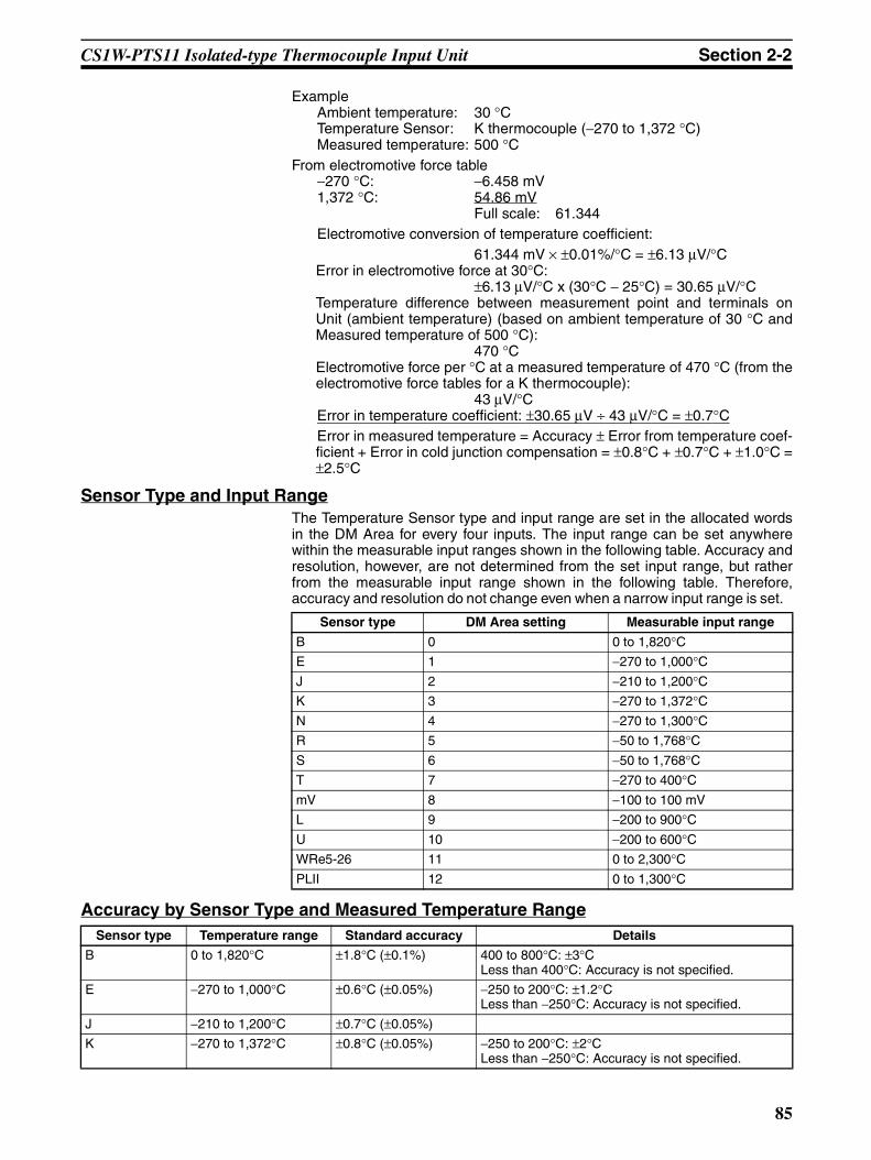
CS1W-PTS11 Isolated-type Thermocouple Input Unit Section 2-2
ExampleAmbient temperature: 30 °CTemperature Sensor: K thermocouple (−270 to 1,372 °C)Measured temperature: 500 °C
From electromotive force table−270 °C: −6.458 mV1,372 °C: 54.86 mV
Full scale: 61.344Electromotive conversion of temperature coefficient:
61.344 mV × ±0.01%/°C = ±6.13 µV/°CError in electromotive force at 30°C:
±6.13 µV/°C x (30°C − 25°C) = 30.65 µV/°CTemperature difference between measurement point and terminals onUnit (ambient temperature) (based on ambient temperature of 30 °C andMeasured temperature of 500 °C):
470 °CElectromotive force per °C at a measured temperature of 470 °C (from theelectromotive force tables for a K thermocouple):
43 µV/°CError in temperature coefficient: ±30.65 µV ÷ 43 µV/°C = ±0.7°CError in measured temperature = Accuracy ± Error from temperature coef-ficient + Error in cold junction compensation = ±0.8°C + ±0.7°C + ±1.0°C =±2.5°C
Sensor Type and Input RangeThe Temperature Sensor type and input range are set in the allocated wordsin the DM Area for every four inputs. The input range can be set anywherewithin the measurable input ranges shown in the following table. Accuracy andresolution, however, are not determined from the set input range, but ratherfrom the measurable input range shown in the following table. Therefore,accuracy and resolution do not change even when a narrow input range is set.
Accuracy by Sensor Type and Measured Temperature Range
Sensor type DM Area setting Measurable input range
B 0 0 to 1,820°CE 1 −270 to 1,000°CJ 2 −210 to 1,200°CK 3 −270 to 1,372°CN 4 −270 to 1,300°CR 5 −50 to 1,768°CS 6 −50 to 1,768°CT 7 −270 to 400°CmV 8 −100 to 100 mV
L 9 −200 to 900°CU 10 −200 to 600°CWRe5-26 11 0 to 2,300°CPLII 12 0 to 1,300°C
Sensor type Temperature range Standard accuracy Details
B 0 to 1,820°C ±1.8°C (±0.1%) 400 to 800°C: ±3°CLess than 400°C: Accuracy is not specified.
E −270 to 1,000°C ±0.6°C (±0.05%) −250 to 200°C: ±1.2°CLess than −250°C: Accuracy is not specified.
J −210 to 1,200°C ±0.7°C (±0.05%)
K −270 to 1,372°C ±0.8°C (±0.05%) −250 to 200°C: ±2°CLess than −250°C: Accuracy is not specified.
85

CS1W-PTS11 Isolated-type Thermocouple Input Unit Section 2-2
DM Area AllocationsFirst word: m = D20000 + unit number × 100 (unit number: 0 to 95)
N −270 to 1,300°C ±0.8°C (±0.05%) −200 to 150°C: ±1.6°CLess than −200°C: Accuracy is not specified.
R −50 to 1,769°C ±1.8°C (±0.1%) 0 to 100°C: ±2.5°CLess than 0°C: Accuracy is not specified.
S −50 to 1,769°C ±1.8°C (±0.1%) 0 to 100°C: ±2.5°CLess than 0°C: 3.2°C
T −270 to 400°C ±0.35°C (±0.05%) −180 to 0°C: ±0.7°C−200 to −180°C: ±1.3°C Less than −200°C: Accuracy is not specified.
L −200 to 900°C ±0.5°C (±0.05%)
U −200 to 600°C ±0.4°C (±0.05%) −100 to 0°C: ±0.5°CLess than −100°C: ±0.7°C
WRe5-26 0 to 2,315°C ±1.2°C (±0.05%) More than 2,200°C: ±1.4°CPLII 0 to 1,395°C ±0.7°C (±0.05%)
Sensor type Temperature range Standard accuracy Details
DM Area address Data range Default Data contents
Input No. 1
Input No. 2
Input No. 3
Input No. 4
Decimal Hexadecimal
m 12345, 0 3039, 0000 hex
0000 hex Default block read commandSpecifies the direction of data transfer when the PLC is turned ON or the Unit is restarted for DM words m+1 to m+93.• 12345 (3039 hex): The data in words m+1
to m+93 is transferred from the Thermo-couple Input Unit to the CPU Unit. Whenthe transfer is completed, the value willbecome 0000 hex.
• Other than 12345 (3039 hex) (such as0000 hex): The data in the allocatedwords of DM Area is transferred from theCPU Unit to the Thermocouple Input Unit.
Number of inputs setting
m + 1 0, 1 0000, 0001 hex
0 (0000 hex)
0: 4 inputs, 1: 2 inputs
Setting Group 1 (continuously refreshed area): Parameters that are continuously refreshed during PLC operation (regardless of the CPU Unit’s operation mode)
Process value alarm settings
m + 2 m + 10 m + 18 m + 26 –32768 to 32767
8000 to FFFF hex, 0000 to 7FFF hex
4200 (1068 hex)
Process value HH (high high limit) alarm setting(Set at process value scaling value.)
m + 3 m + 11 m + 19 m + 27 –32768 to 32767
8000 to FFFF hex, 0000 to 7FFF hex
4000 (0FA0 hex)
Process value H (high limit) alarm setting(Set at process value scaling value.)
m + 4 m + 12 m + 20 m + 28 –32768 to 32767
8000 to FFFF hex, 0000 to 7FFF hex
0 (0000 hex)
Process value L (low limit) alarm setting(Set at process value scaling value.)
m + 5 m + 13 m + 21 m + 29 –32768 to 32767
8000 to FFFF hex, 0000 to 7FFF hex
–200 (FF38 hex)
Process value LL (low low limit) alarm set-ting(Set at process value scaling value.)
Rate-of-change value alarm settings
m + 6 m + 14 m + 22 m + 30 –32768 to 32767
8000 to FFFF hex, 0000 to 7FFF hex
4000 (0FA0 hex)
Rate-of-change value H (high limit) alarm setting(Set at rate-of-change scaling value.)
m + 7 m + 15 m + 23 m + 31 –32768 to 32767
8000 to FFFF hex, 0000 to 7FFF hex
0 (0000 hex)
Rate-of-change value L (low limit) alarm set-ting(Set at rate-of-change scaling value.)
Zero/span adjustment
m + 8 m + 16 m + 24 m + 32 0 to 32000 0000 to 7D00 hex
10000 (2710 hex)
Gain for span adjustment(set value x 0.0001%)
86

CS1W-PTS11 Isolated-type Thermocouple Input Unit Section 2-2
m + 9 m + 17 m + 25 m + 33 –32000 to 32000
8300 to FFFF hex,0000 to 7D00 hex
0 (0000 hex)
Zero adjustment value(Set at process value scaling value.)
Setting Group 2 (initial settings area): Parameters that are transferred one time from the CPU Unit to the Thermocouple Input Unit if word m contains other than 12345 when the PLC is turned ON or the Thermocouple Input Unit is restarted.
m + 34 m + 49 m + 64 m + 79 0 to 12 0000 to 000C hex
0 (0000 hex)
Sensor type0: B, 1: E, 2: J, 3: K, 4: N, 5: R, 6: S, 7: T, 8: mV, 9: L, 10: U, 11: Wre5-26, 12: PLII
Process value input range settings
m + 35 m + 50 m + 65 m + 80 –32000 to 32000
8300 to FFFF hex, 0000 to 7D00 hex
4000 (0FA0 hex)
Maximum input signal value(set value x 0.1°C/°F or mV)
m + 36 m + 51 m + 66 m + 81 –32000 to 32000
8300 to FFFF hex, 0000 to 7D00 hex
0 (0000 hex)
Minimum input signal value(set value x 0.1°C/°F or mV)
m + 37 m + 52 m + 67 m + 82 0, 1 0000, 0001 hex
0 (0000 hex)
Unit0: °C, 1: °F
m + 38 m + 53 m + 68 m + 83 0, 1 0000, 0001 hex
0 (0000 hex)
Process value overrange direction at time of input disconnection0: High; 1: Low
Process value scaling
m + 39 m + 54 m + 69 m + 84 –32000 to 32000
8300 to FFFF hex, 0000 to 7D00 hex
4000 (0FA0 hex)
Value stored for maximum value in range (span)
m + 40 m + 55 m + 70 m + 85 –32000 to 32000
8300 to FFFF hex, 0000 to 7D00 hex
0 (0000 hex)
Value stored for minimum value in range (zero)
Alarm supplementary functions
m + 41 m + 56 m + 71 m + 86 0 to 32000 0000 to 7D00 hex
40 (0028 hex)
Alarm hysteresis(Set at process value scaling value. Shared with process value alarm and rate-of-change alarm.)
m + 42 m + 57 m + 72 m + 87 0 to 60 0000 to 003C hex
0 (0000 hex)
Alarm ON-delay time (Unit: s)(Shared with process value alarm and rate-of-change alarm.)
Rate-of-change function
m + 43 m + 58 m + 73 m + 88 –32000 to 32000
8300 to FFFF hex, 0000 to 7D00 hex
4000 (0FA0 hex)
Rate-of-change range setting
Maximum rate-of-change value (Set value industrial unit; comparison time interval)
m + 44 m + 59 m + 74 m + 89 –32000 to 32000
8300 to FFFF hex, 0000 to 7D00 hex
–4000 (F060 hex)
Minimum rate-of-change value (Set value industrial unit; comparison time interval)
m + 45 m + 60 m + 75 m + 90 1 to 16 0001 to 0010 hex
1 (0001 hex)
Rate-of-change comparison time interval (Unit: s)
m + 46 m + 61 m + 76 m + 91 –32000 to 32000
8300 to FFFF hex, 0000 to 7D00 hex
4000 (0FA0 hex)
Rate-of-change value scaling
Value stored for maxi-mum value in range
m + 47 m + 62 m + 77 m + 92 –32000 to 32000
8300 to FFFF hex, 0000 to 7D00 hex
–4000 (F060 hex)
Value stored for minimum value in range
Mean value processing function
m + 48 m + 63 m + 78 m + 93 1 to 128 0001 to 0080 hex
25(0019 hex)
Number of process values for calculating moving average for mean value processing
Display parameter
m + 94 m + 95 m + 96 m + 97 0 to 99, 100 to 1XX
0000 to 0063 hex, 0064 to 0XXX hex
0 (0000 hex)
Address of Data Range Error (See note.)
DM Area address Data range Default Data contents
Input No. 1
Input No. 2
Input No. 3
Input No. 4
Decimal Hexadecimal
87

CS1W-PTS11 Isolated-type Thermocouple Input Unit Section 2-2
Note 1. The ERC indicator on the Unit’s front panel will light if an out-of-range set-ting is made in either Setting Group 1 (continuously refreshed area) or 2(initial settings area), or in the Expansion Setting Area. The offset fromword m to the first word containing the out-of-range error will be stored asthe Address of Data Range Error in the DM Area in four digits hexadecimal.If the first memory address containing the out-of-range error is in the Ex-pansion Setting Area, the Address of Data Range Error will be over +100(or +100 if the first word in the Expansion Setting Area is an error).
2. When specifying an expansion setting area, be sure that it does not over-lap with other areas that are being used. If areas overlap, the words thatare allocated may be overwritten, resulting in unexpected operation.
3. When specifying the first word in an expansion setting area, be sure thatthe end of the memory area is not exceeded.
Expansion Setting AreaFirst word: word o. (o = address specified in word m+99 in the area specifiedin word m+98 in the DM Area)
Expansion Setting Area allocations
m+98 0 to 5 0000 to 0005 hex
--- Expansion Setting Area allocations:0: Not used; 1: DM; 2: CIO; 3: W; 4: H; 5: EM
m+99 0 to 32767 0000 to 7FFF hex
--- Expansion Setting Area first word
DM Area address Data range Default Data contents
Input No. 1
Input No. 2
Input No. 3
Input No. 4
Decimal Hexadecimal
DM Area address Data range Default Data contents
Input No. 1
Input No. 2
Input No. 3
Input No. 4
Decimal Hexadecimal
Setting Group 3 (initial settings area): Parameters that are transferred one time from the CPU Unit to the Thermocouple Input Unit if word m contains other than 12345, and if Expansion Setting Area settings are allocated, when the PLC is turned ON or the Thermocou-ple Input Unit is restarted.
Expansion Control/Monitor Area set-tings
o 0 to 5 0000 to 0005 hex
--- Expansion Control/Monitor Area allocation0: Not used. 1: DM; 2: CIO; 3: W; 4: H; 5: EM
o+1 0 to 32767 0000 to 7FFF hex
--- Expansion Control/Monitor Area first word
Zero/span adjustment supplementary function
o+2 o+13 o+24 o+35 0 to 32000 0000 to 7D00 hex
10000 (2710 hex)
Span adjustment position(Input span percentage)
o+3 o+14 o+25 o+36 −32000 to 32000
8300 to FFFF hex, 0000 to 7D00 hex
0 (0000 hex) Zero adjustment position(Input span percentage)
o+4 o+15 o+26 o+37 0 to 9999 0000 to 270F hex
365 (016D hex) Zero/span adjustment period (Unit: Days)
o+5 o+16 o+27 o+38 0 to 9999 0000 to 270F hex
30 (001E hex) Notice of days remaining (Unit: Days)
Not used.
o+6 o+17 o+28 o+39 --- --- 0 (0000 hex) Not used.
o+7 o+18 o+29 o+40
o+8 o+19 o+30 o+41
Top and valley hold
o+9 o+20 o+31 o+42 0 to 32000 0000 to 7D00 hex
40 (0028 hex) Hysteresis
Not used.
88
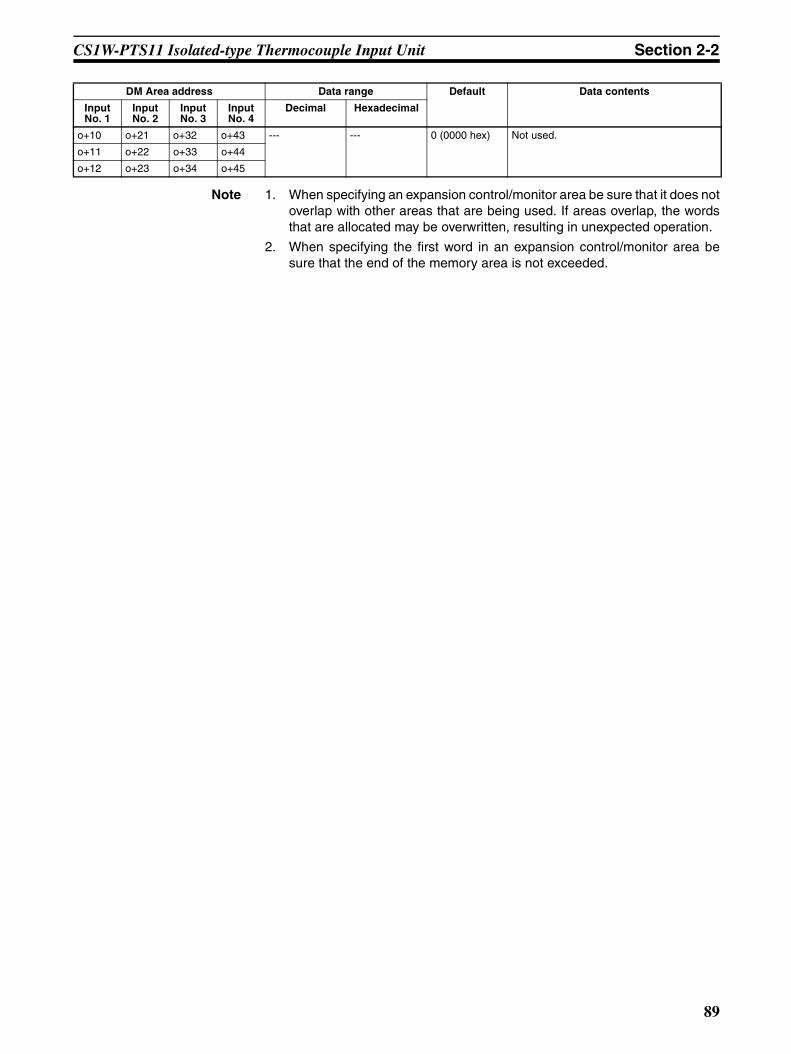
CS1W-PTS11 Isolated-type Thermocouple Input Unit Section 2-2
Note 1. When specifying an expansion control/monitor area be sure that it does notoverlap with other areas that are being used. If areas overlap, the wordsthat are allocated may be overwritten, resulting in unexpected operation.
2. When specifying the first word in an expansion control/monitor area besure that the end of the memory area is not exceeded.
o+10 o+21 o+32 o+43 --- --- 0 (0000 hex) Not used.
o+11 o+22 o+33 o+44
o+12 o+23 o+34 o+45
DM Area address Data range Default Data contents
Input No. 1
Input No. 2
Input No. 3
Input No. 4
Decimal Hexadecimal
89
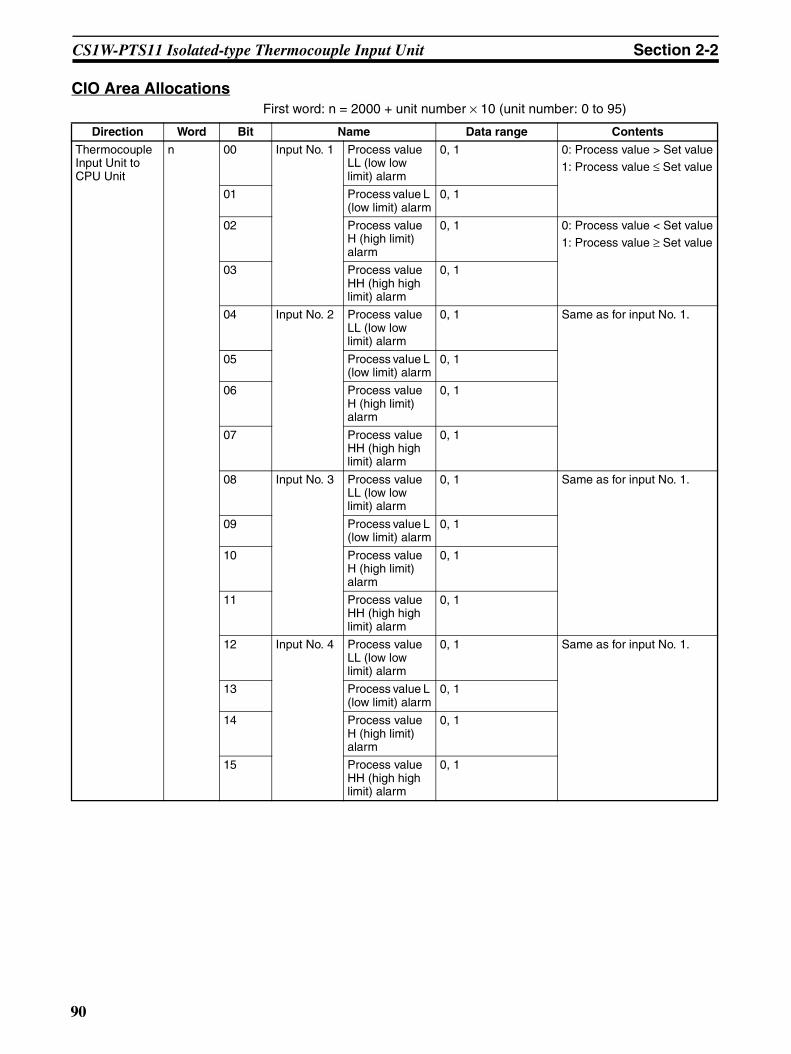
CS1W-PTS11 Isolated-type Thermocouple Input Unit Section 2-2
CIO Area AllocationsFirst word: n = 2000 + unit number × 10 (unit number: 0 to 95)
Direction Word Bit Name Data range Contents
Thermocouple Input Unit to CPU Unit
n 00 Input No. 1 Process value LL (low low limit) alarm
0, 1 0: Process value > Set value1: Process value ≤ Set value
01 Process value L (low limit) alarm
0, 1
02 Process value H (high limit) alarm
0, 1 0: Process value < Set value1: Process value ≥ Set value
03 Process value HH (high high limit) alarm
0, 1
04 Input No. 2 Process value LL (low low limit) alarm
0, 1 Same as for input No. 1.
05 Process value L (low limit) alarm
0, 1
06 Process value H (high limit) alarm
0, 1
07 Process value HH (high high limit) alarm
0, 1
08 Input No. 3 Process value LL (low low limit) alarm
0, 1 Same as for input No. 1.
09 Process value L (low limit) alarm
0, 1
10 Process value H (high limit) alarm
0, 1
11 Process value HH (high high limit) alarm
0, 1
12 Input No. 4 Process value LL (low low limit) alarm
0, 1 Same as for input No. 1.
13 Process value L (low limit) alarm
0, 1
14 Process value H (high limit) alarm
0, 1
15 Process value HH (high high limit) alarm
0, 1
90

CS1W-PTS11 Isolated-type Thermocouple Input Unit Section 2-2
Thermocouple Input Unit to CPU Unit
n + 1 00 to 15 Input No. 1 process value –32768 to 32767 (8000 to FFFF hex, 0000 to 7FFF hex)
The present process value is stored according to the scal-ing set in the allocated words of the DM Area.n + 2 00 to 15 Input No. 2 process value –32768 to 32767
(8000 to FFFF hex, 0000 to 7FFF hex)
n + 3 00 to 15 Input No. 3 process value –32768 to 32767 (8000 to FFFF hex, 0000 to 7FFF hex)
n + 4 00 to 15 Input No. 4 process value –32768 to 32767 (8000 to FFFF hex, 0000 to 7FFF hex)
n + 5 00 to 15 Input No. 1 rate-of-change value
–32768 to 32767 (8000 to FFFF hex, 0000 to 7FFF hex)
The process value rate of change is stored according to the scaling set in the allo-cated words of the DM Area.n + 6 00 to 15 Input No. 2 rate-of-change
value–32768 to 32767 (8000 to FFFF hex, 0000 to 7FFF hex)
n + 7 00 to 15 Input No. 3 rate-of-change value
–32768 to 32767 (8000 to FFFF hex, 0000 to 7FFF hex)
n + 8 00 to 15 Input No. 4 rate-of-change value
–32768 to 32767 (8000 to FFFF hex, 0000 to 7FFF hex)
n + 9 00 Input No. 1 Rate-of-change value L (low limit) alarm
0, 1 0: Rate-of-change value > Set value1: Rate-of-change value ≤ Set value
01 Rate-of-change value H (high limit) alarm
0, 1 0: Rate-of-change value < Set value
1: Rate-of-change value ≥ Set value
02 Input No. 2 Rate-of-change value L (low limit) alarm
0, 1 Same as for input No. 1.
03 Rate-of-change value H (high limit) alarm
04 Input No. 3 Rate-of-change value L (low limit) alarm
05 Rate-of-change value H (high limit) alarm
06 Input No. 4 Rate-of-change value L (low limit) alarm
07 Rate-of-change value H (high limit) alarm
08 Input No. 1 input disconnec-tion
0, 1 0: Normal1: Disconnection
09 Input No. 2 input disconnec-tion
0, 1
10 Input No. 3 input disconnec-tion
0, 1
11 Input No. 4 input disconnec-tion
0, 1
Direction Word Bit Name Data range Contents
91

CS1W-PTS11 Isolated-type Thermocouple Input Unit Section 2-2
Expansion Control/Monitor Area AllocationsFirst word: word p. (p = address specified in word o+1 in the area specified inword o in the Expansion Setting Area)
Thermocouple Input Unit to CPU Unit
n + 9 12 Cold junction sensor error 0, 1 0: Normal1: Error
13 Zero/span adjustment period end
0, 1 0: Adjustment enabled1: Adjustment ended
14 Zero/span adjustment period notice
0, 1 0: Adjustment enabled1: Notice period
15 Not used. 0
Direction Word Bit Name Data range Contents
Direction Word Bit Name Data range Contents
CPU Unit to Thermocou-ple Input Unit
p 00 to 15
Not used. 0 (0000 hex) Not used.
p+1 00 Input No. 1 hold function selection 0, 1 0: Peak and bottom1: Top and valley01 Input No. 2 hold function selection
02 Input No. 3 hold function selection
03 Input No. 4 hold function selection
04 to 07
Not used. 0 Not used.
08 Input No. 1 hold start 0, 1 0: Do not hold.1: Hold09 Input No. 2 hold start
10 Input No. 3 hold start
11 Input No. 4 hold start
12 Input No. 1 hold value reset 0, 1 0: Normal operation1: Reset hold value.13 Input No. 2 hold value reset
14 Input No. 3 hold value reset
15 Input No. 4 hold value reset
p+2 00 Input No. 1 zero/span adjustment update bit 0, 1 0: Normal operation1: Update adjustment date(Remains ON while writing external FROM.)
01 Input No. 2 zero/span adjustment update bit
02 Input No. 3 zero/span adjustment update bit
03 Input No. 4 zero/span adjustment update bit
04 to 15
Not used. 0 Not used.
92
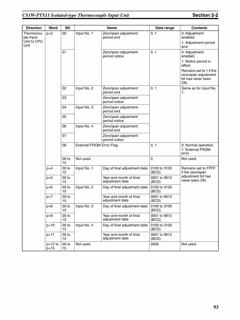
CS1W-PTS11 Isolated-type Thermocouple Input Unit Section 2-2
Thermocou-ple Input Unit to CPU Unit
p+3 00 Input No. 1 Zero/span adjustment period end
0, 1 0: Adjustment enabled.
1: Adjustment period end
01 Zero/span adjustment period notice
0, 1 0: Adjustment enabled.1: Notice period in effect.Remains set to 1 if the zero/span adjustment bit has never been ON.
02 Input No. 2 Zero/span adjustment period end
0, 1 Same as for input No. 1.
03 Zero/span adjustment period notice
04 Input No. 3 Zero/span adjustment period end
05 Zero/span adjustment period notice
06 Input No. 4 Zero/span adjustment period end
07 Zero/span adjustment period notice
08 External FROM Error Flag 0, 1 0: Normal operation1: External FROM error
09 to 15
Not used. 0 Not used.
p+4 00 to 15
Input No. 1 Day of final adjustment date 0100 to 3100 (BCD)
Remains set to FFFF if the zero/span adjustment bit has never been ON.
p+5 00 to 15
Year and month of final adjustment date
0001 to 9912 (BCD)
p+6 00 to 15
Input No. 2 Day of final adjustment date 0100 to 3100 (BCD)
p+7 00 to 15
Year and month of final adjustment date
0001 to 9912 (BCD)
p+8 00 to 15
Input No. 3 Day of final adjustment date 0100 to 3100 (BCD)
p+9 00 to 15
Year and month of final adjustment date
0001 to 9912 (BCD)
p+10 00 to 15
Input No. 4 Day of final adjustment date 0100 to 3100 (BCD)
p+11 00 to 15
Year and month of final adjustment date
0001 to 9912 (BCD)
p+12 to p+15
00 to 15
Not used. 0000 Not used.
Direction Word Bit Name Data range Contents
93
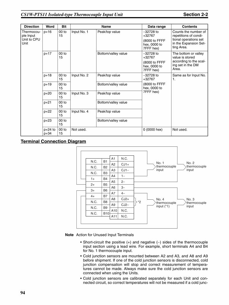
CS1W-PTS11 Isolated-type Thermocouple Input Unit Section 2-2
Terminal Connection Diagram
Note Action for Unused Input Terminals
• Short-circuit the positive (+) and negative (−) sides of the thermocoupleinput section using a lead wire. For example, short terminals A4 and B4for No. 1 thermocouple input.
• Cold junction sensors are mounted between A2 and A3, and A8 and A9before shipment. If one of the cold junction sensors is disconnected, coldjunction compensation will stop and correct measurement of tempera-tures cannot be made. Always make sure the cold junction sensors areconnected when using the Units.
• Cold junction sensors are calibrated separately for each Unit and con-nected circuit, so correct temperatures will not be measured if a cold junc-
Thermocou-ple Input Unit to CPU Unit
p+16 00 to 15
Input No. 1 Peak/top value −32728 to +32767
(8000 to FFFF hex, 0000 to 7FFF hex)
Counts the number of repetitions of condi-tional operations set in the Expansion Set-ting Area.
p+17 00 to 15
Bottom/valley value −32728 to +32767
(8000 to FFFF hex, 0000 to 7FFF hex)
The bottom or valley value is stored according to the scal-ing set in the DM Area.
p+18 00 to 15
Input No. 2 Peak/top value −32728 to +32767(8000 to FFFF hex, 0000 to 7FFF hex)
Same as for Input No. 1.
p+19 00 to 15
Bottom/valley value
p+20 00 to 15
Input No. 3 Peak/top value
p+21 00 to 15
Bottom/valley value
p+22 00 to 15
Input No. 4 Peak/top value
p+23 00 to 15
Bottom/valley value
p+24 to p+34
00 to 15
Not used. 0 (0000 hex) Not used.
Direction Word Bit Name Data range Contents
N.C.
N.C.
N.C.
1+
2+
3+
4+
N.C.
N.C.
N.C.
B1
B2
B3
B4
B5
B6
B7
B8
B9
B10
A1
A2
A3
A4
A5
A6
A7
A8
A9
A10
A11
N.C.
CJ1+
CJ1−
1−
2−
3−
4−
CJ2+
CJ2−
N.C.
N.C.
*2
No. 1 thermocouple input
No. 2 thermocouple input
No. 4 thermocouple input (*1)
No. 3 thermocouple input
94

CS1W-PTS11 Isolated-type Thermocouple Input Unit Section 2-2
tion sensor from another Unit is used or if the two cold junction sensors ina Unit are swapped. Use the cold junction sensors as they are provided,without making any changes.
• When wiring No. 4 thermocouple input terminals (*1 in the above dia-gram), remove the cold junction sensor between terminals CJ2+ andCJ2− at the bottom (*2 in the above diagram), connect the No. 4 thermo-couple input, and then reconnect the cold junction sensor. Any attempt toconnect No. 4 thermocouple input without removing the cold junction sen-sor may result in damage to the cold junction sensor.
• Always ground the GR terminal on the Power Supply Unit of the PLC.• If the input device uses a voltage generator, temperature compensator, or
similar device, then ground the input device if it has a ground terminal.
Terminal Block Diagram
Error Processing
Conversion Data Does Not Change.
Probable cause Remedy
The gain for span adjustment is set to 0.
Set the gain for span adjustment to a value other than 0.
The minimum and maximum val-ues for process value scaling are either the same or are set extremely low.
Set the minimum and maximum values correctly.
The sensor type, input range, or process value scaling is not set correctly.
Check and correct the settings.
An input device is malfunctioning, input wiring is faulty, or wiring is disconnected.
Check whether the input voltage or current has changed. Check for faulty or disconnected wir-ing. Check whether a wiring disconnection has been detected in the I/O Area.
No. 2 input
No. 1 input
26 VDC
Thermocouples
No. 3 input
No. 41 input
B4
A4
B5
A5
B6
A6
B7
A7
A2 A3
A8 A9
Photocoupler
Photocoupler
Photocoupler
Photocoupler
5 VDC
Con
nect
or
Inpu
t sel
ecto
r
Mul
tiple
xer
A/D
con
vert
er
Pho
toco
uple
r
Upper
Lower
Cold junction sensors
Amplifier circuit
Amplifier circuit
Amplifier circuit
Amplifier circuit
Amplifier circuit
Amplifier circuit
A/D converter
A/D converter
A/D converter
A/D converter
Digital circuits
Isolated power supply circuit
Isolated power supply circuit
Isolated power supply circuit
Isolated power supply circuit
Isolated power supply circuit
95

CS1W-PTS11 Isolated-type Thermocouple Input Unit Section 2-2
Values are Not Converted as Intended.
Converted Values are Unstable.
Probable cause Remedy
The sensor type, input range, or process value scaling is not set correctly.
Check and correct the settings.
The zero/span adjustment data is incorrect.
Check and correct the zero/span adjustment set-tings.
Cold junction compensation is not operating.
Check the Cold Junction Error Flag.
A compensation conductor has not been used or a different com-pensation conductor is used.
Use the correct compensation conductor for the thermocouple.
Incorrect input wiring (incorrect thermocouple or compensation conductor polarity.)
Correct the input wiring.
Probable cause Remedy
Input signals are being affected by external noise.
Change the connection paths of the input signal lines. (Separate them from sources of noise or use shielded cable.)
Insert a 0.01 to 0.1 µF ceramic capacitor between the positive (+) and negative (−) input terminals.
Increase the number of values for calculating the moving average in mean value processing.
The process value scaling value is greater than the Unit’s resolution.
Reduce the process value scaling value.
The input signal range setting is too small.
Match the input signal range to the internal ranges.
96
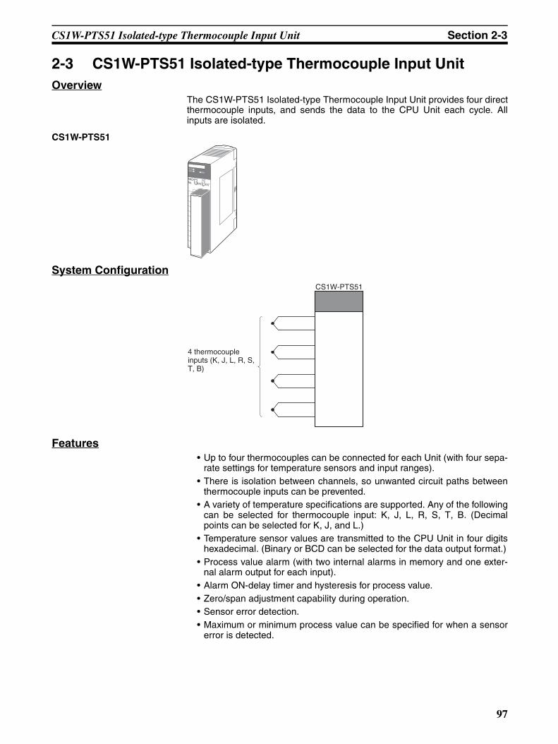
CS1W-PTS51 Isolated-type Thermocouple Input Unit Section 2-3
2-3 CS1W-PTS51 Isolated-type Thermocouple Input UnitOverview
The CS1W-PTS51 Isolated-type Thermocouple Input Unit provides four directthermocouple inputs, and sends the data to the CPU Unit each cycle. Allinputs are isolated.
CS1W-PTS51
System Configuration
Features• Up to four thermocouples can be connected for each Unit (with four sepa-
rate settings for temperature sensors and input ranges).• There is isolation between channels, so unwanted circuit paths between
thermocouple inputs can be prevented.• A variety of temperature specifications are supported. Any of the following
can be selected for thermocouple input: K, J, L, R, S, T, B. (Decimalpoints can be selected for K, J, and L.)
• Temperature sensor values are transmitted to the CPU Unit in four digitshexadecimal. (Binary or BCD can be selected for the data output format.)
• Process value alarm (with two internal alarms in memory and one exter-nal alarm output for each input).
• Alarm ON-delay timer and hysteresis for process value.• Zero/span adjustment capability during operation.• Sensor error detection.• Maximum or minimum process value can be specified for when a sensor
error is detected.
MACHNo.
X100
FEDCBA9876543210 FEDCBA9876543
210X101
RUNERC
ERH
CS1W-PTS51
4 thermocouple inputs (K, J, L, R, S, T, B)
97

CS1W-PTS51 Isolated-type Thermocouple Input Unit Section 2-3
Model Information
Block Diagram (Order of Processing)The processing for the inputs is as shown in the following diagram.
Unit classification
Model number Inputs Temperature sensor types
CS-series Special I/O Unit
CS1W-PTS51 4 K, J, L, R, S, T, B
When input disconnection is detected
Zero/span adjustment
Input calculations
Thermocouple typeInput rangeCold junction temperature compensation
A/D conversion
H, L
CPU Unit
I/O refresh
Process value Process value alarm Sensor error
CPU Unit Expansion Area Allocations
Isolated-type Thermocouple Input Unit
Process value alarm
Cold junction sensor error
Cold junction temperature compensation
Thermocouple
Upper cold junction sensor
External alarm output
98
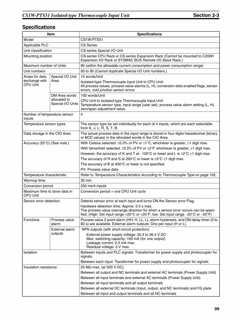
CS1W-PTS51 Isolated-type Thermocouple Input Unit Section 2-3
SpecificationsItem Specifications
Model CS1W-PTS51
Applicable PLC CS Series
Unit classification CS-series Special I/O Unit
Mounting position CS-series CPU Rack or CS-series Expansion Rack (Cannot be mounted to C200H Expansion I/O Rack or SYSMAC BUS Remote I/O Slave Rack.)
Maximum number of Units 80 (within the allowable current consumption and power consumption range)
Unit numbers 00 to 95 (Cannot duplicate Special I/O Unit numbers.)
Areas for data exchange with CPU Unit
Special I/O Unit Area
10 words/Unit
Isolated-type Thermocouple Input Unit to CPU Unit:All process values, process value alarms (L, H), conversion data enabled flags, sensor errors, cold junction sensor errors
DM Area words allocated to Special I/O Units
100 words/UnitCPU Unit to Isolated-type Thermocouple Input Unit:Temperature sensor type, input range (user set), process value alarm setting (L, H), zero/span adjustment value.
Number of temperature sensor inputs
4
Temperature sensor types The sensor type be set individually for each of 4 inputs, which are each selectable from K, J, L, R, S, T, B.
Data storage in the CIO Area The actual process data in the input range is stored in four digits hexadecimal (binary or BCD values) in the allocated words in the CIO Area.
Accuracy (25°C) (See note.) With Celsius selected: ±0.3% of PV or ±1°C, whichever is greater, ±1 digit max. With fahrenheit selected: ±0.3% of PV or ±2°F, whichever is greater, ±1 digit max.
However, the accuracy of K and T at −100°C or lower and L is ±2°C ±1 digit max.The accuracy of R and S at 200°C or lower is ±3°C ±1 digit max.The accuracy of B at 400°C or lower is not specified.
PV: Process value data
Temperature characteristic Refer to Temperature Characteristics According to Thermocouple Type on page 102.
Warmup time 30 min
Conversion period 250 ms/4 inputs.
Maximum time to store data in CPU Unit
Conversion period + one CPU Unit cycle
Sensor error detection Detects sensor error at each input and turns ON the Sensor error Flag.Hardware detection time: Approx. 0.5 s max.The process value overrange direction for when a sensor error occurs can be speci-fied. (High: Set input range +20°C or +20°F; low: Set input range −20°C or −20°F)
Functions Process value alarm
Process value 2-point alarm (HH, H, LL, L), alarm hysteresis, and ON-delay timer (0 to 60 s) are available. External alarm outputs: One per input (H or L).
External alarm outputs
NPN outputs (with short-circuit protection)External power supply voltage: 20.4 to 26.4 V DCMax. switching capacity: 100 mA (for one output) Leakage current: 0.3 mA max.Residual voltage: 3 V max.
Isolation Between inputs and PLC signals: Transformer for power supply and photocoupler for signals.Between each input: Transformer for power supply and photocoupler for signals.
Insulation resistance 20 MΩ max. (at 500 V DC).Between all output and NC terminals and external AC terminals (Power Supply Unit)
Between all input terminals and external AC terminals (Power Supply Unit)Between all input terminals and all output terminalsBetween all external DC terminals (input, output, and NC terminals) and FG plate
Between all input and output terminals and all NC terminals
99

CS1W-PTS51 Isolated-type Thermocouple Input Unit Section 2-3
Note The heat generated by a Unit will dramatically change the accuracy specifica-tions when more than one C200HW-PA209R or CS1W-ID291 Unit is mountedside-by-side. The following accuracy specifications apply under such conditions.With Celsius selected: ±0.3% of PV or ±1.3°C, whichever is greater, ±1 digit max. With Fahrenheit selected: ±0.3% of PV or ±3°F, whichever is greater, ±1 digit max.However, the accuracy of K and T at −100°C or less and L is ±3°C ±1 digitmax. The accuracy of R and S at 200°C or less is ±4°C ±1 digit max.The accuracy of B at 400°C or less is not specified.
Sensor Type and Input RangeThe Temperature Sensor type and input range are set in the allocated wordsin the DM Area for every four inputs. The measurable data range is ±20 digits wider than the sensor input range.
Dielectric strength Between all output and NC terminals and external AC terminals (Power Supply Unit)2,000 VAC, 50/60 Hz 1 min., detection current: 1 mA
Between all input terminals and external AC terminals (Power Supply Unit)Between all input terminals and all output terminalsBetween all external DC terminals (input, output, and NC terminals) and FG plate1,000 VAC, 50/60 Hz 1 min., detection current: 1 mABetween all channels500 VAC, 50/60 Hz 1 min., detection current: 1 mA
External connections Terminal block (detachable)
Unit number settings Set by rotary switches on front panel, from 0 to 95.
Indicators Seven LED indicators on front panel (for normal operation, errors detected at the Thermocouple Input Unit, errors related to the CPU Unit, and four indicators for exter-nal alarm outputs.)
Effect on CPU Unit cycle time 0.4 ms
Current consumption (supplied from Power Supply Unit)
5 V DC at 250 mA max.
Dimensions 35 × 130 × 126 mm (W × H × D)
Note The height including the Backplane is 145 mm.
Weight 450 g max.
Item Specifications
Set-ting
Input °C °F16-bit binary BCD 16-bit binary BCD
F@@@ indicates
minus sign.
Leftmost bit indicates
minus sign.
F@@@ indicates
minus sign.
Leftmost bit indicates
minus sign.
0 K: −200 to 1300°C(−300 to 2300°F)
FF38 to FFFF to 0514(−200 to −1 to 1300)
F200 to 1300(−200 to 1300)
8200 to 1300(−200 to 1300)
FED4 to FFFF to 08FC(−300 to −1 to 2300)
F300 to 2300(−300 to 2300)
F300 to 2300(−300 to 2300)
1 K: 0.0 to 500°C(0.0 to 900.0°F)
0000 to 1388(0.0 to 500.0)
0000 to 5000(0.0 to 500.0)
0000 to 5000(0.0 to 500.0)
0000 to 2328(0.0 to 900.0)
0000 to 9000(0.0 to 900.0)
0000 to 7999 (See note 3.)(0.0 to 799.9)
2 J: −100 to 850°C(−100 to 1500°F)
FF9C to FFFF to 0352(−100 to −1 to 850)
F100 to 0850(−100 to 850)
8100 to 0850(−100 to 850)
FF9C to FFFF to 05DC(−100 to −1 to 1500)
F100 to 1500(−100 to 1500)
8100 to 1500(−100 to 1500)
3 J: 0.0 to 400.0°C(0.0 to 750.0°F)
0000 to 0FA0(0.0 to 400.0)
0000 to 4000(0.0 to 400.0)
0000 to 4000(0.0 to 400.0)
0000 to 1D4C(0.0 to 750.0)
0000 to 7500(0.0 to 750.0)
0000 to 7500(0.0 to 750.0)
100

CS1W-PTS51 Isolated-type Thermocouple Input Unit Section 2-3
Note 1. If the indication range is exceeded, a sensor error will occur and the sensorerror bit will turn ON. The process value will be clamped at the lower or up-per limit of the indication range, depending on the setting for data directionat sensor error.
2. The lower limit for B thermocouples is 0°C/°F.
3. The indicator range for BCD display will be clamped at the lower (or upper)limit in the region between the lower (or upper) limit of the setting rangeand the point where a sensor error occurs.For 0.1°C/0.1°F indication with minus sign indicated by leftmost 4 bits (bits12 to 15): Lower limit = −99.9, Upper limit = 999.9.For 0.1°C/0.1°F indication with minus sign indicated by leftmost bit (bit 15):Lower limit = −799.9, Upper limit = 799.9.
4 T: −200 to 400°C(−300 to 700.0°F)
F830 to FFFF to 0FA0(−200.0 to −0.1 to 400.0)
F999 to 4000 (See note 3.)(−99.9 to 400.0)
A000 to 4000(−200.0 to 400.0)
F448 to FFFF to 1B58(−300.0 to −0.1 to 700.0)
F999 to 7000 (See note 3.)(−99.9 to 700.0)
B000 to 7000(−300.0 to 700.0)
5 L: −100 to 850°C(−100 to 1500°F)
FF9C to FFFF to 0352(−100 to −1 to 850)
F100 to 0850(−100 to 850)
8100 to 0850(−100 to 850)
FF9C to FFFF to 05DC(−100 to −1 to 1500)
F100 to 1500(−100 to 1500)
8100 to 1500(−100 to 1500)
6 L: 0.0 to 400.0°C(0.0 to 750.0°F)
0000 to 0FA0(0.0 to 400.0)
0000 to 4000(0.0 to 400.0)
0000 to 4000(0.0 to 400.0)
0000 to 1D4C(0.0 to 750.0)
0000 to 7500(0.0 to 750.0)
0000 to 7500(0.0 to 750.0)
7 R: 0 to 1700°C(0 to 3000°F)
0000 to 06A4(0 to 1700)
0000 to 1700(0 to 1700)
0000 to 1700(0 to 1700)
0000 to 0BB8(0 to 3000)
0000 to 3000(0 to 3000)
0000 to 3000(0 to 3000)
8 S: 0 to 1700°C(0 to 3000°F)
0000 to 06A4(0 to 1700)
0000 to 1700(0 to 1700)
0000 to 1700(0 to 1700)
0000 to 0BB8(0 to 3000)
0000 to 3000(0 to 3000)
0000 to 3000(0 to 3000)
9 B: 400 to 1800°C (See note 2.)(750 to 3200°F)
0190 to 0708(400 to 1800)
0400 to 1800(400 to 1800)
0400 to 1800(400 to 1800)
02EE to 0C80(750 to 3200)
0750 to 3200(750 to 3200)
0750 to 3200(750 to 3200)
Set-ting
Input °C °F16-bit binary BCD 16-bit binary BCD
F@@@ indicates
minus sign.
Leftmost bit indicates
minus sign.
F@@@ indicates
minus sign.
Leftmost bit indicates
minus sign.
101

CS1W-PTS51 Isolated-type Thermocouple Input Unit Section 2-3
Temperature Characteristics According to Thermocouple Type
The measured temperature error is calculated as shown in the followingexample.
Overall accuracy = Reference accuracy + Temperature characteristic × Change in ambient tem-perature = ±1.5°C + ±0.143°C × 5 = Approx. ±2.2°C ± 1 digit.
Thermocouple Temperature range Set value error when ambient temperature changes by 1°C
R 0 to 200°C ±0.43°C200 to 1,000°C ±0.29°C1,000 to 1,700°C ±285 ppm of PV
S 0 to 200°C ±0.43°C200 to 1,000°C ±0.29°C1,000 to 1,700°C 285 ppm of PV
B 400°C or less Not specified.
400 to 800°C ±0.43°C800 to 1,000°C ±0.29°C1,000 to 1,800°C 285 ppm of PV
K −200 to −100°C ±0.29°C−100 to 400°C ±0.11°C400 to 1,300°C ±285 ppm of PV
J −100 to 400°C ±0.11°C400 to 850°C ±285 ppm of PV
T −200 to −100°C ±0.29°C−100 to 400°C ±0.11°C
L −100 to 400°C ±0.11°C400 to 850°C ±285 ppm of PV
Item Details
Ambient temperature 30°CThermocouple type K
Measured temperature (PV) 500°CReference accuracy (25°C) ±0.3°C of PV or ±1°C, whichever is greater, ±1 digit.
In this example, ±1.5°C.
Temperature characteristics 400 to 1,300°C: 285 ppm of PV.
In this example, 285 ppm × 500°C = 0.143°C.
Change in ambient temper-ature
5°C (25 to 30°C).
102
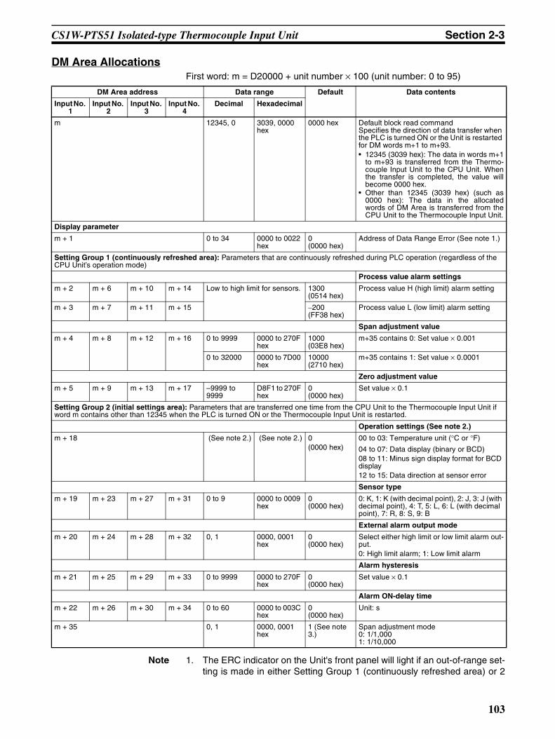
CS1W-PTS51 Isolated-type Thermocouple Input Unit Section 2-3
DM Area AllocationsFirst word: m = D20000 + unit number × 100 (unit number: 0 to 95)
Note 1. The ERC indicator on the Unit's front panel will light if an out-of-range set-ting is made in either Setting Group 1 (continuously refreshed area) or 2
DM Area address Data range Default Data contents
Input No. 1
Input No. 2
Input No. 3
Input No. 4
Decimal Hexadecimal
m 12345, 0 3039, 0000 hex
0000 hex Default block read commandSpecifies the direction of data transfer when the PLC is turned ON or the Unit is restarted for DM words m+1 to m+93.• 12345 (3039 hex): The data in words m+1
to m+93 is transferred from the Thermo-couple Input Unit to the CPU Unit. Whenthe transfer is completed, the value willbecome 0000 hex.
• Other than 12345 (3039 hex) (such as0000 hex): The data in the allocatedwords of DM Area is transferred from theCPU Unit to the Thermocouple Input Unit.
Display parameter
m + 1 0 to 34 0000 to 0022 hex
0 (0000 hex)
Address of Data Range Error (See note 1.)
Setting Group 1 (continuously refreshed area): Parameters that are continuously refreshed during PLC operation (regardless of the CPU Unit’s operation mode)
Process value alarm settings
m + 2 m + 6 m + 10 m + 14 Low to high limit for sensors. 1300 (0514 hex)
Process value H (high limit) alarm setting
m + 3 m + 7 m + 11 m + 15 −200 (FF38 hex)
Process value L (low limit) alarm setting
Span adjustment value
m + 4 m + 8 m + 12 m + 16 0 to 9999 0000 to 270F hex
1000 (03E8 hex)
m+35 contains 0: Set value × 0.001
0 to 32000 0000 to 7D00 hex
10000 (2710 hex)
m+35 contains 1: Set value × 0.0001
Zero adjustment value
m + 5 m + 9 m + 13 m + 17 –9999 to 9999
D8F1 to 270F hex
0 (0000 hex)
Set value × 0.1
Setting Group 2 (initial settings area): Parameters that are transferred one time from the CPU Unit to the Thermocouple Input Unit if word m contains other than 12345 when the PLC is turned ON or the Thermocouple Input Unit is restarted.
Operation settings (See note 2.)
m + 18 (See note 2.) (See note 2.) 0(0000 hex)
00 to 03: Temperature unit (°C or °F)
04 to 07: Data display (binary or BCD)08 to 11: Minus sign display format for BCD display12 to 15: Data direction at sensor error
Sensor type
m + 19 m + 23 m + 27 m + 31 0 to 9 0000 to 0009 hex
0 (0000 hex)
0: K, 1: K (with decimal point), 2: J, 3: J (with decimal point), 4: T, 5: L, 6: L (with decimal point), 7: R, 8: S, 9: B
External alarm output mode
m + 20 m + 24 m + 28 m + 32 0, 1 0000, 0001 hex
0 (0000 hex)
Select either high limit or low limit alarm out-put.0: High limit alarm; 1: Low limit alarm
Alarm hysteresis
m + 21 m + 25 m + 29 m + 33 0 to 9999 0000 to 270F hex
0 (0000 hex)
Set value × 0.1
Alarm ON-delay time
m + 22 m + 26 m + 30 m + 34 0 to 60 0000 to 003C hex
0 (0000 hex)
Unit: s
m + 35 0, 1 0000, 0001 hex
1 (See note 3.)
Span adjustment mode0: 1/1,0001: 1/10,000
103

CS1W-PTS51 Isolated-type Thermocouple Input Unit Section 2-3
(initial settings area). The offset from word m to the first word containingthe out-of-range error will be stored as the Address of Data Range Error inthe DM Area in four digits hexadecimal.
2. The operation settings are shown in the following table.
Example: For a temperature in degrees Celsius (°C), a binary data format,and a data direction at sensor error of “lower limit,” word m+18 will contain1000.3. Indicates the value after transferring the default value (set when 12345 is
written to word m).
CIO Area AllocationsFirst word: n = 2000 + unit number × 10 (unit number: 0 to 95)
Word Bits Description Settings
m+18 00 Temperature unit setting 0: °C1: °F
04 Data format 0: Binary (Negative values are given as 2’s comple-ments).1: BCD
08 Minus sign display format for BCD display 0: “F” used to indicate the minus sign.1: Leftmost bit used to indicate the minus sign.The setting is disabled if bits 04 to 07 are set to 0.
12 Data direction at sensor error 0: Goes to upper limit at sensor error1: Goes to lower limit at sensor error
Direction Word Bit Name Data range Contents
Thermocouple Input Unit to CPU Unit
n 00 Input No. 1 Process value L (low limit) alarm
0, 1 0: Process value > Set value
1: Process value ≤ Set value
01 Process value H (high limit) alarm
0, 1 0: Process value < Set value
1: Process value ≥ Set value
02 Input No. 2 Process value L (low limit) alarm
0, 1 Same as for input No. 1.
03 Process value H (high limit) alarm
0, 1
04 Input No. 3 Process value L (low limit) alarm
0, 1
05 Process value H (high limit) alarm
0, 1
06 Input No. 4 Process value L (low limit) alarm
0, 1
07 Process value H (high limit) alarm
0, 1
08 to 15 Not used.
n + 1 00 to 15 Input No. 1 Process value Depends on type of input.
Stores data in the data range specified for the input type ±20 digits.
n + 2 00 to 15 Input No. 2
n + 3 00 to 15 Input No. 3
n + 4 00 to 15 Input No. 4
104

CS1W-PTS51 Isolated-type Thermocouple Input Unit Section 2-3
Note The Conversion Data Enabled Flag remains OFF after the PLC is turned ONor the Unit is restarted until the AD conversion data becomes stable (approxi-mately 2 to 4 s), then is ON during operation.
Terminal Connection Diagram
Note Action for Unused Input Terminals
• Short-circuit the positive (+) and negative (−) sides of the thermocoupleinput section using a lead wire. For example, short terminals A3 and A2for No. 1 thermocouple input.
• Cold junction sensors are mounted before shipment. If one of the coldjunction sensors is disconnected, cold junction compensation will stopand correct measurement of temperatures cannot be made. Always makesure the cold junction sensors are connected when using the Units.
• Cold junction sensors are calibrated separately for each Unit and con-nected circuit, so correct temperatures will not be measured if a cold junc-tion sensor from another Unit is used or if the two cold junction sensors ina Unit are swapped. Use the cold junction sensors as they are provided,without making any changes.
Thermocouple Input Unit to CPU Unit
n + 5 00 to 15 Not used.
n + 6 00 to 15
n + 7 00 to 15
n + 8 00 to 15
n + 9 00 Input No. 1 Sensor error 0, 1 0: Normal1: Error01 Input No. 2 0, 1
02 Input No. 3 0, 1
03 Input No. 4 0, 1
04 Not used.
05
06
07
08 Cold junction sensor error 0, 1 0: Normal1: Error
09 to 14 Not used.
15 Conversion data enabled flag (See note.)
0, 1 0: Data disabled1: Data enabled
Direction Word Bit Name Data range Contents
External alarm outputs
2−2+
CJ
CJ
4−4+
ALM2
ALM4
0V
N.C.
B1
B2
B3
B4
B5
B6
B7
B8
B9
B10
A1
A2
A3
A4
A5
A6
A7
A8
A9
A10
A11
N.C
1−1+
N.C.
N.C.
3−3+
ALM1
ALM3
24V
N.C.
No. 2 thermocouple input
Cold junction sensor
No. 4 thermocouple input
No. 1 thermocouple input
No. 3 thermocouple input
External alarm outputsL
L
L
L
105

CS1W-PTS51 Isolated-type Thermocouple Input Unit Section 2-3
• Do not connect anything to NC terminals. Do not use NC terminals asrelay terminals.
• Always ground the GR terminal on the Power Supply Unit of the PLC.• If the input device uses a voltage generator, temperature compensator, or
similar device, then ground the input device if it has a ground terminal.
Terminal Block Diagram
Input Circuits
5 VDC
Con
nect
or
No. 1 inputAmplifier circuit
Photocoupler
A3
A2
No. 2 inputAmplifier circuit
Photocoupler
B2
B4
No. 3 inputAmplifier circuit
Photocoupler
A7
A6
No. 4 inputAmplifier circuit
Photocoupler
B6
B5
Cold junction sensors
Double integral A/D
Amplifier circuit
Reference power supply
Photocoupler
B3
B4
Isol
atio
n ci
rcui
t
Digital circuits
Double integral A/D
Reference power supply
Double integral A/D
Reference power supply
Double integral A/D
Reference power supply
Double integral A/D
Reference power supply
106

CS1W-PTS51 Isolated-type Thermocouple Input Unit Section 2-3
Output Circuits
Error Processing
Conversion Data Does Not Change.
Inte
rnal
Circ
uit
L
L
L
L
Output DisplayLED
B7ALM2
A9ALM3
B8ALM4
B90V
A1024V
A8ALM1
Probable cause Remedy
The gain for span adjustment is set to 0.
Set the gain for span adjustment to a value other than 0.
The sensor type, input range, or process value scaling is not set correctly.
Check and correct the settings.
An input device is malfunctioning, input wiring is faulty, or wiring is disconnected.
Check whether the input voltage or current has changed. Check for faulty or disconnected wir-ing. Check whether a sensor error has been detected in the I/O Area.
107

CS1W-PTS51 Isolated-type Thermocouple Input Unit Section 2-3
Values are Not Converted as Intended.
Converted Values are Unstable.
Probable cause Remedy
The sensor type is not set cor-rectly.
Check and correct the settings.
The zero/span adjustment data is incorrect.
Check and correct the zero/span adjustment set-tings.
Cold junction compensation is not operating.
Check the Cold Junction Error Flag.
A compensation conductor has not been used or a different com-pensation conductor is used.
Use the correct compensation conductor for the thermocouple.
Incorrect input wiring (incorrect thermocouple or compensation conductor polarity.)
Correct the input wiring.
Thermocouple lead or compensat-ing conductor is too long and mea-surements are being affected by conductor resistance.
Use a thicker compensating conductor.Change the wiring position and shorten the com-pensating conductor.
The terminal block temperature is not uniform due to radiated heat from peripheral devices.
Mount the unit in a position unaffected by radi-ated heat.
Probable cause Remedy
Input signals are being affected by external noise.
Change the connection paths of the input signal lines. (Separate them from sources of noise or use shielded cable.)
Insert a 0.01 to 0.1 µF ceramic capacitor between the positive (+) and negative (−) input terminals.
An airflow is hitting the Unit termi-nal block.
Move the terminal block to a position unaffected by airflow.
108

CS1W-PTS55 Isolated-type Thermocouple Input Unit Section 2-4
2-4 CS1W-PTS55 Isolated-type Thermocouple Input UnitOverview
The CS1W-PTS55 Isolated-type Thermocouple Input Unit provides 8 directthermocouple inputs, and sends the data to the CPU Unit each cycle. Allinputs are isolated.
CS1W-PTS55
System Configuration
Features• Up to 8 thermocouples can be connected for each Unit (with 8 separate
settings for temperature sensors and input ranges).• There is isolation between channels, so unwanted circuit paths between
thermocouple inputs can be prevented.• A variety of temperature specifications are supported. Any of the following
can be selected for thermocouple input: K, J, L, R, S, T, B. (Decimalpoints can be selected for K, J, and L.)
• Temperature sensor values are transmitted to the CPU Unit in four digitshexadecimal. (Binary or BCD can be selected for the data output format.)
• Process value alarms (Two internal alarms per input can be output tomemory and two alarms per input can be output to specified I/O memoryarea addresses using indirect address specifications).
• Alarm ON-delay timer and hysteresis for process value.• Zero/span adjustment capability during operation.• Sensor error detection.• Maximum or minimum process value can be specified for when a sensor
error is detected.
MACHNo.
X100
FEDCBA9876543210 FEDCBA9876543
210X101
RUNERC
ERH
CS1W-PTS55
8 thermocouple inputs (K, J, L, R, S, T, B)
109

CS1W-PTS55 Isolated-type Thermocouple Input Unit Section 2-4
Model Information
Block Diagram (Order of Processing)The processing for the inputs is as shown in the following diagram.
Unit classification
Model number Inputs Temperature sensor types
CS-series Special I/O Unit
CS1W-PTS55 8 K, J, L, R, S, T, B
Alarm Output
Zero/span adjustment
Input calculations
Thermocouple typeInput rangeCold junction temperature compensation
A/D conversion
H, L
CPU Unit
I/O refresh
Process value Process value alarm Cold junction sensor error
Isolated-type Thermocouple Input Unit
Process value alarm
Cold junction temperature compensation
Thermocouple
Upper cold junction sensor
Expansion Setting Area
Lower cold junction sensor
Output limit
CPU Unit CIO Area
Sensor error
110

CS1W-PTS55 Isolated-type Thermocouple Input Unit Section 2-4
SpecificationsItem Specifications
Model CS1W-PTS55
Applicable PLC CS Series
Unit classification CS-series Special I/O Unit
Mounting position CS-series CPU Rack or CS-series Expansion Rack (Cannot be mounted to C200H Expansion I/O Rack or SYSMAC BUS Remote I/O Slave Rack.)
Maximum number of Units 80 (within the allowable current consumption and power consumption range)
Unit numbers 00 to 95 (Cannot duplicate Special I/O Unit numbers.)
Areas for data exchange with CPU Unit
Special I/O Unit Area
10 words/Unit
Isolated-type Thermocouple Input Unit to CPU Unit:All process values, process value alarms (L, H), conversion data enabled flags, sensor errors, cold junction sensor errors
DM Area words allocated to Special I/O Units
100 words/UnitCPU Unit to Isolated-type Thermocouple Input Unit:Temperature sensor type, input range (user set), process value alarm setting (L, H), zero/span adjustment value.
Expansion Set-ting Area
1 word/Unit
CPU Unit to Isolated-type Thermocouple Input Unit:Process Value Alarm
Number of temperature sensor inputs
8
Temperature sensor types The sensor type be set individually for each of 8 inputs, which are each selectable from K, J, L, R, S, T, B (“Not used” can be selected).
Data storage in the CIO Area The actual process data in the input range is stored in four digits hexadecimal (binary or BCD values) in the allocated words in the CIO Area.
Accuracy (25°C) With Celsius selected: ±0.3% of PV or ±1°C, whichever is greater, ±1 digit max. With fahrenheit selected: ±0.3% of PV or ±2°F, whichever is greater, ±1 digit max.
However, the accuracy of K and T at −100°C or lower and L is ±2°C ±1 digit max.The accuracy of R and S at 200°C or lower is ±3°C ±1 digit max.
The accuracy of B at 400°C or lower is not specified.PV: Process value data
Temperature characteristic Refer to Temperature Characteristics According to Thermocouple Type on page 113.
Warmup time 30 min
Conversion period 250 ms/8 inputs.
Maximum time to store data in CPU Unit
Conversion period + one CPU Unit cycle
Sensor error detection Detects sensor error at each input and turns ON the Sensor error Flag.Hardware detection time: Approx. 0.5 s max.The process value overrange direction for when a sensor error occurs can be speci-fied. (High: Set input range +20°C or +20°F; low: Set input range −20°C or −20°F)
Functions Process value alarm
Process value 2-point alarm (H, L), alarm hysteresis, and ON-delay timer (0 to 60 s) are available. Two alarms per input (H, L) can be output to addresses in the CIO Area specified in the Expansion Setting Area.
Isolation Between inputs and PLC signals: Transformer for power supply and photocoupler for signals.Between each input: Transformer for power supply and photocoupler for signals.
Insulation resistance 20 MΩ max. (at 500 V DC).Between all input terminals and external AC terminals (Power Supply Unit)
Between all external DC terminals (input and NC terminals) and FG plateBetween all input and all NC terminals
111

CS1W-PTS55 Isolated-type Thermocouple Input Unit Section 2-4
Sensor Type and Input RangeThe Temperature Sensor type and input range are set in the allocated wordsin the DM Area for every four inputs. The measurable data range is ±20 digits wider than the sensor input range.
Dielectric strength Between NC terminals and external AC terminals (Power Supply Unit)2,000 VAC, 50/60 Hz 1 min., detection current: 1 mA
Between all input terminals and external AC terminals (Power Supply Unit)Between all external DC terminals (input and NC terminals) and FG plate1000 VAC, 50/60 Hz 1 min., detection current: 1 mA
Between all channels500 VAC, 50/60 Hz 1 min., detection current: 1 mA
External connections Terminal block (detachable)
Unit number settings Set by rotary switches on front panel, from 0 to 95.
Indicators Three LED indicators on front panel (for normal operation, errors detected at the Unit, errors related to the CPU Unit)
Effect on CPU Unit cycle time 0.4 ms
Current consumption (supplied from Power Supply Unit)
5 V DC at 180 mA max.26 V DC at 60 mA max.
Dimensions 35 × 130 × 126 mm (W × H × D)Note The height including the Backplane is 145 mm.
Weight 450 g max.
Item Specifications
Set-ting
Input °C °F16-bit binary BCD 16-bit binary BCD
F@@@ indicates
minus sign.
Leftmost bit indicates
minus sign.
F@@@ indicates
minus sign.
Leftmost bit indicates
minus sign.
0 K: −200 to 1300°C(−300 to 2300°F)
FF38 to FFFF to 0514(−200 to −1 to 1300)
F200 to 1300(−200 to 1300)
8200 to 1300(−200 to 1300)
FED4 to FFFF to 08FC(−300 to −1 to 2300)
F300 to 2300(−300 to 2300)
F300 to 2300(−300 to 2300)
1 K: 0.0 to 500°C(0.0 to 900.0°F)
0000 to 1388(0.0 to 500.0)
0000 to 5000(0.0 to 500.0)
0000 to 5000(0.0 to 500.0)
0000 to 2328(0.0 to 900.0)
0000 to 9000(0.0 to 900.0)
0000 to 7999 (See note 3.)(0.0 to 799.9)
2 J: −100 to 850°C(−100 to 1500°F)
FF9C to FFFF to 0352(−100 to −1 to 850)
F100 to 0850(−100 to 850)
8100 to 0850(−100 to 850)
FF9C to FFFF to 05DC(−100 to −1 to 1500)
F100 to 1500(−100 to 1500)
8100 to 1500(−100 to 1500)
3 J: 0.0 to 400.0°C(0.0 to 750.0°F)
0000 to 0FA0(0.0 to 400.0)
0000 to 4000(0.0 to 400.0)
0000 to 4000(0.0 to 400.0)
0000 to 1D4C(0.0 to 750.0)
0000 to 7500(0.0 to 750.0)
0000 to 7500(0.0 to 750.0)
4 T: −200 to 400°C(−300 to 700.0°F)
F830 to FFFF to 0FA0(−200.0 to −0.1 to 400.0)
F999 to 4000 (See note 3.)(−99.9 to 400.0)
A000 to 4000(−200.0 to 400.0)
F448 to FFFF to 1B58(−300.0 to −0.1 to 700.0)
F999 to 7000 (See note 3.)(−99.9 to 700.0)
B000 to 7000(−300.0 to 700.0)
5 L: −100 to 850°C(−100 to 1500°F)
FF9C to FFFF to 0352(−100 to −1 to 850)
F100 to 0850(−100 to 850)
8100 to 0850(−100 to 850)
FF9C to FFFF to 05DC(−100 to −1 to 1500)
F100 to 1500(−100 to 1500)
8100 to 1500(−100 to 1500)
6 L: 0.0 to 400.0°C(0.0 to 750.0°F)
0000 to 0FA0(0.0 to 400.0)
0000 to 4000(0.0 to 400.0)
0000 to 4000(0.0 to 400.0)
0000 to 1D4C(0.0 to 750.0)
0000 to 7500(0.0 to 750.0)
0000 to 7500(0.0 to 750.0)
7 R: 0 to 1700°C(0 to 3000°F)
0000 to 06A4(0 to 1700)
0000 to 1700(0 to 1700)
0000 to 1700(0 to 1700)
0000 to 0BB8(0 to 3000)
0000 to 3000(0 to 3000)
0000 to 3000(0 to 3000)
112

CS1W-PTS55 Isolated-type Thermocouple Input Unit Section 2-4
Note 1. If the indication range is exceeded, a sensor error will occur and the sensorerror bit will turn ON. The process value will be clamped at the lower or up-per limit of the indication range, depending on the setting for data directionat sensor error.
2. The lower limit for B thermocouples is 0°C/°F.
3. The indicator range for BCD display will be clamped at the lower (or upper)limit in the region between the lower (or upper) limit of the setting rangeand the point where a sensor error occurs.For 0.1°C/0.1°F indication with minus sign indicated by leftmost 4 bits (bits12 to 15): Lower limit = −99.9, Upper limit = 999.9.For 0.1°C/0.1°F indication with minus sign indicated by leftmost bit (bit 15):Lower limit = −799.9, Upper limit = 799.9.
Temperature Characteristics According to Thermocouple Type
The measured temperature error is calculated as shown in the followingexample.
8 S: 0 to 1700°C(0 to 3000°F)
0000 to 06A4(0 to 1700)
0000 to 1700(0 to 1700)
0000 to 1700(0 to 1700)
0000 to 0BB8(0 to 3000)
0000 to 3000(0 to 3000)
0000 to 3000(0 to 3000)
9 B: 400 to 1800°C (See note 2.)(750 to 3200°F)
0190 to 0708(400 to 1800)
0400 to 1800(400 to 1800)
0400 to 1800(400 to 1800)
02EE to 0C80(750 to 3200)
0750 to 3200(750 to 3200)
0750 to 3200(750 to 3200)
Set-ting
Input °C °F16-bit binary BCD 16-bit binary BCD
F@@@ indicates
minus sign.
Leftmost bit indicates
minus sign.
F@@@ indicates
minus sign.
Leftmost bit indicates
minus sign.
Thermocouple Temperature range Set value error when ambient temperature changes by 1°C
R 0 to 200°C ±0.43°C200 to 1,000°C ±0.29°C1,000 to 1,700°C ±285 ppm of PV
S 0 to 200°C ±0.43°C200 to 1,000°C ±0.29°C1,000 to 1,700°C 285 ppm of PV
B 400°C or less Not specified.
400 to 800°C ±0.43°C800 to 1,000°C ±0.29°C1,000 to 1,800°C 285 ppm of PV
K −200 to −100°C ±0.29°C−100 to 400°C ±0.11°C400 to 1,300°C ±285 ppm of PV
J −100 to 400°C ±0.11°C400 to 850°C ±285 ppm of PV
T −200 to −100°C ±0.29°C−100 to 400°C ±0.11°C
L −100 to 400°C ±0.11°C400 to 850°C ±285 ppm of PV
Item Details
Ambient temperature 30°CThermocouple type K
Measured temperature (PV) 500°C
113
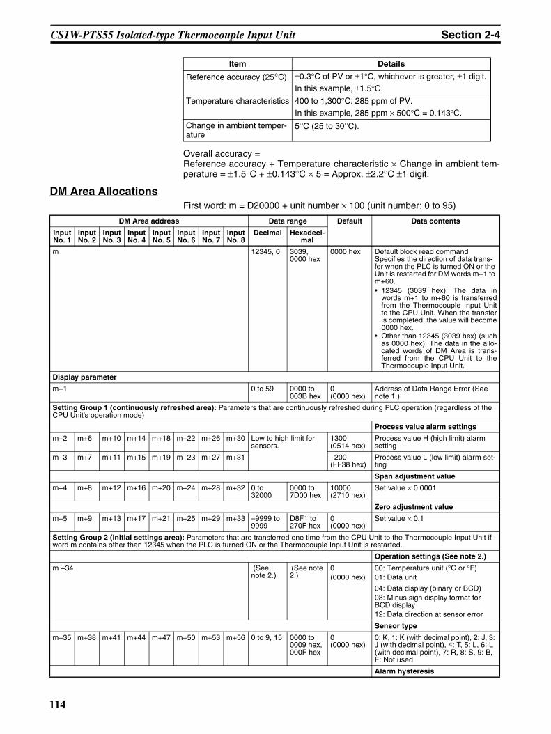
CS1W-PTS55 Isolated-type Thermocouple Input Unit Section 2-4
Overall accuracy = Reference accuracy + Temperature characteristic × Change in ambient tem-perature = ±1.5°C + ±0.143°C × 5 = Approx. ±2.2°C ±1 digit.
DM Area AllocationsFirst word: m = D20000 + unit number × 100 (unit number: 0 to 95)
Reference accuracy (25°C) ±0.3°C of PV or ±1°C, whichever is greater, ±1 digit.In this example, ±1.5°C.
Temperature characteristics 400 to 1,300°C: 285 ppm of PV.In this example, 285 ppm × 500°C = 0.143°C.
Change in ambient temper-ature
5°C (25 to 30°C).
Item Details
DM Area address Data range Default Data contents
Input No. 1
Input No. 2
Input No. 3
Input No. 4
Input No. 5
Input No. 6
Input No. 7
Input No. 8
Decimal Hexadeci-mal
m 12345, 0 3039, 0000 hex
0000 hex Default block read commandSpecifies the direction of data trans-fer when the PLC is turned ON or the Unit is restarted for DM words m+1 to m+60.• 12345 (3039 hex): The data in
words m+1 to m+60 is transferredfrom the Thermocouple Input Unitto the CPU Unit. When the transferis completed, the value will become0000 hex.
• Other than 12345 (3039 hex) (suchas 0000 hex): The data in the allo-cated words of DM Area is trans-ferred from the CPU Unit to theThermocouple Input Unit.
Display parameter
m+1 0 to 59 0000 to 003B hex
0 (0000 hex)
Address of Data Range Error (See note 1.)
Setting Group 1 (continuously refreshed area): Parameters that are continuously refreshed during PLC operation (regardless of the CPU Unit’s operation mode)
Process value alarm settings
m+2 m+6 m+10 m+14 m+18 m+22 m+26 m+30 Low to high limit for sensors.
1300 (0514 hex)
Process value H (high limit) alarm setting
m+3 m+7 m+11 m+15 m+19 m+23 m+27 m+31 −200 (FF38 hex)
Process value L (low limit) alarm set-ting
Span adjustment value
m+4 m+8 m+12 m+16 m+20 m+24 m+28 m+32 0 to 32000
0000 to 7D00 hex
10000 (2710 hex)
Set value × 0.0001
Zero adjustment value
m+5 m+9 m+13 m+17 m+21 m+25 m+29 m+33 –9999 to 9999
D8F1 to 270F hex
0 (0000 hex)
Set value × 0.1
Setting Group 2 (initial settings area): Parameters that are transferred one time from the CPU Unit to the Thermocouple Input Unit if word m contains other than 12345 when the PLC is turned ON or the Thermocouple Input Unit is restarted.
Operation settings (See note 2.)
m +34 (See note 2.)
(See note 2.)
0(0000 hex)
00: Temperature unit (°C or °F)01: Data unit
04: Data display (binary or BCD)08: Minus sign display format for BCD display12: Data direction at sensor error
Sensor type
m+35 m+38 m+41 m+44 m+47 m+50 m+53 m+56 0 to 9, 15 0000 to 0009 hex, 000F hex
0 (0000 hex)
0: K, 1: K (with decimal point), 2: J, 3: J (with decimal point), 4: T, 5: L, 6: L (with decimal point), 7: R, 8: S, 9: B, F: Not used
Alarm hysteresis
114
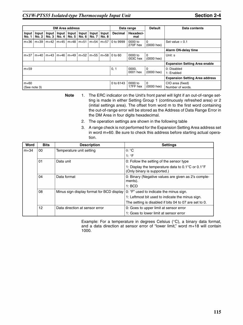
CS1W-PTS55 Isolated-type Thermocouple Input Unit Section 2-4
Note 1. The ERC indicator on the Unit's front panel will light if an out-of-range set-ting is made in either Setting Group 1 (continuously refreshed area) or 2(initial settings area). The offset from word m to the first word containingthe out-of-range error will be stored as the Address of Data Range Error inthe DM Area in four digits hexadecimal.
2. The operation settings are shown in the following table
3. A range check is not performed for the Expansion Setting Area address setin word m+60. Be sure to check this address before starting actual opera-tion.
Example: For a temperature in degrees Celsius (°C), a binary data format,and a data direction at sensor error of “lower limit,” word m+18 will contain1000.
m+36 m+39 m+42 m+45 m+48 m+51 m+54 m+57 0 to 9999 0000 to 270F hex
0 (0000 hex)
Set value × 0.1
Alarm ON-delay time
m+37 m+40 m+43 m+46 m+49 m+52 m+55 m+58 0 to 60 0000 to 003C hex
0 (0000 hex)
Unit: s
Expansion Setting Area enable
m+59 0, 1 0000, 0001 hex
0 (0000 hex)
0: Disabled1: Enabled
Expansion Setting Area address
m+60(See note 3)
0 to 6143 0000 to 17FF hex
0 (0000 hex)
CIO area (fixed)Number of words.
DM Area address Data range Default Data contents
Input No. 1
Input No. 2
Input No. 3
Input No. 4
Input No. 5
Input No. 6
Input No. 7
Input No. 8
Decimal Hexadeci-mal
Word Bits Description Settings
m+34 00 Temperature unit setting 0: °C1: °F
01 Data unit 0: Follow the setting of the sensor type
1: Display the temperature data to 0.1°C or 0.1°F (Only binary is supported.)
04 Data format 0: Binary (Negative values are given as 2’s comple-ments).1: BCD
08 Minus sign display format for BCD display 0: “F” used to indicate the minus sign.1: Leftmost bit used to indicate the minus sign.
The setting is disabled if bits 04 to 07 are set to 0.
12 Data direction at sensor error 0: Goes to upper limit at sensor error1: Goes to lower limit at sensor error
115

CS1W-PTS55 Isolated-type Thermocouple Input Unit Section 2-4
Expansion Setting AreaFirst word: word o. (o = address specified in word m+60 in the DM Area)
Note If either of the following changes is made for the Expansion Setting Area forthe CS1W-PTS55/PTS56/PDC55, the previous data will be left in the Expan-sion Setting Area even after the change has been made.Clear the previous data when changing either of these settings.
• The Expansion Setting Area Enable setting is changed from “enabled” to“disabled.”
• The Expansion Setting Area Address setting is changed while the Expan-sion Setting Area Enable setting is set to “enabled.”
Direction Word Bit Name Data range Contents
Thermocouple Input Unit to CPU Unit
o 00 Input No. 1 Process value L (low limit) alarm
0, 1 0: Process value > Set value1: Process value ≤ Set value
01 Process value H (high limit) alarm
0, 1 0: Process value < Set value1: Process value ≥ Set value
02 Input No. 2 Process value L (low limit) alarm
0, 1 Same as for input No. 1.
03 Process value H (high limit) alarm
0, 1
04 Input No. 3 Process value L (low limit) alarm
0, 1
05 Process value H (high limit) alarm
0, 1
06 Input No. 4 Process value L (low limit) alarm
0, 1
07 Process value H (high limit) alarm
0, 1
08 Input No. 5 Process value L (low limit) alarm
0, 1
09 Process value H (high limit) alarm
0, 1
10 Input No. 6 Process value L (low limit) alarm
0, 1
11 Process value H (high limit) alarm
0, 1
12 Input No. 7 Process value L (low limit) alarm
0, 1
13 Process value H (high limit) alarm
0, 1
14 Input No. 8 Process value L (low limit) alarm
0, 1
15 Process value H (high limit) alarm
0, 1
116
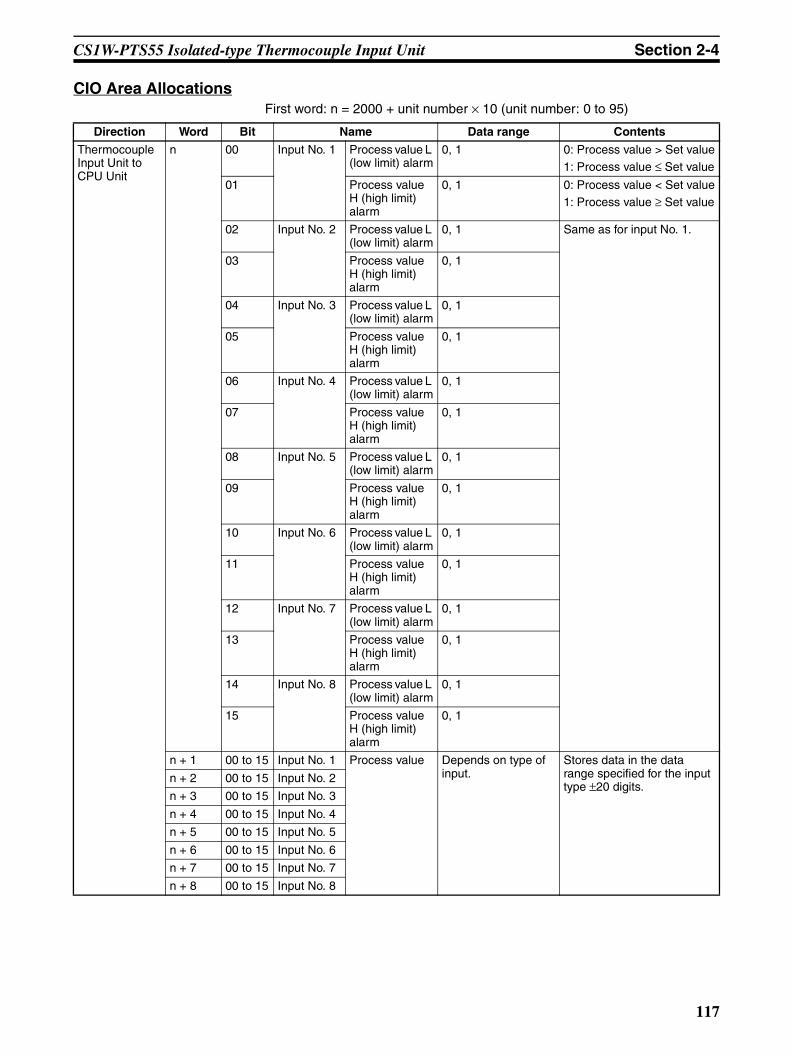
CS1W-PTS55 Isolated-type Thermocouple Input Unit Section 2-4
CIO Area AllocationsFirst word: n = 2000 + unit number × 10 (unit number: 0 to 95)
Direction Word Bit Name Data range Contents
Thermocouple Input Unit to CPU Unit
n 00 Input No. 1 Process value L (low limit) alarm
0, 1 0: Process value > Set value1: Process value ≤ Set value
01 Process value H (high limit) alarm
0, 1 0: Process value < Set value1: Process value ≥ Set value
02 Input No. 2 Process value L (low limit) alarm
0, 1 Same as for input No. 1.
03 Process value H (high limit) alarm
0, 1
04 Input No. 3 Process value L (low limit) alarm
0, 1
05 Process value H (high limit) alarm
0, 1
06 Input No. 4 Process value L (low limit) alarm
0, 1
07 Process value H (high limit) alarm
0, 1
08 Input No. 5 Process value L (low limit) alarm
0, 1
09 Process value H (high limit) alarm
0, 1
10 Input No. 6 Process value L (low limit) alarm
0, 1
11 Process value H (high limit) alarm
0, 1
12 Input No. 7 Process value L (low limit) alarm
0, 1
13 Process value H (high limit) alarm
0, 1
14 Input No. 8 Process value L (low limit) alarm
0, 1
15 Process value H (high limit) alarm
0, 1
n + 1 00 to 15 Input No. 1 Process value Depends on type of input.
Stores data in the data range specified for the input type ±20 digits.
n + 2 00 to 15 Input No. 2
n + 3 00 to 15 Input No. 3
n + 4 00 to 15 Input No. 4
n + 5 00 to 15 Input No. 5
n + 6 00 to 15 Input No. 6
n + 7 00 to 15 Input No. 7
n + 8 00 to 15 Input No. 8
117

CS1W-PTS55 Isolated-type Thermocouple Input Unit Section 2-4
Note The Conversion Data Enabled Flag remains OFF after the PLC is turned ONor the Unit is restarted until the AD conversion data becomes stable (approxi-mately 2 to 4 s), then is ON during operation.
Terminal Connection Diagram
Note • Set the Sensor type in Setting Group 2 in the DM Area to “Not used” forany thermocouple inputs that are not used.
• Cold junction sensors are mounted before shipment. If one of the coldjunction sensors is disconnected, cold junction compensation will stop
Thermocouple Input Unit to CPU Unit
n + 9 00 Input No. 1 Sensor error 0, 1 0: Normal1: Error01 Input No. 2 0, 1
02 Input No. 3 0, 1
03 Input No. 4 0, 1
04 Input No. 5 0, 1
05 Input No. 6 0, 1
06 Input No. 7 0, 1
07 Input No. 8 0, 1
08 Cold junction sensor 1 error 0, 1 0: Normal1: Error09 Cold junction sensor 2 error 0, 1
10 to 14 Not used.
15 Conversion data enabled flag (See note.)
0, 1 0: Data disabled1: Data enabled
Direction Word Bit Name Data range Contents
N.C.
N.C.
1+
2+
3+
4+
5+
6+
7+
8+
B1
B2
B3
B4
B5
B6
B7
B8
B9
B10
A1
A2
A3
A4
A5
A6
A7
A8
A9
A10
A11
Cold junction sensor
N.C. B11
N.C. B12A12
CJ1+
CJ1-
1-
2-
3-
4-
5-
6-
7-
8-
CJ2+
CJ2-Cold junction sensor
No. 8 thermocouple input
No. 7 thermocouple input
No. 6 thermocouple input
No. 5 thermocouple input
No. 4 thermocouple input
No. 3 thermocouple input
No. 2 thermocouple input
No. 1 thermocouple input
118
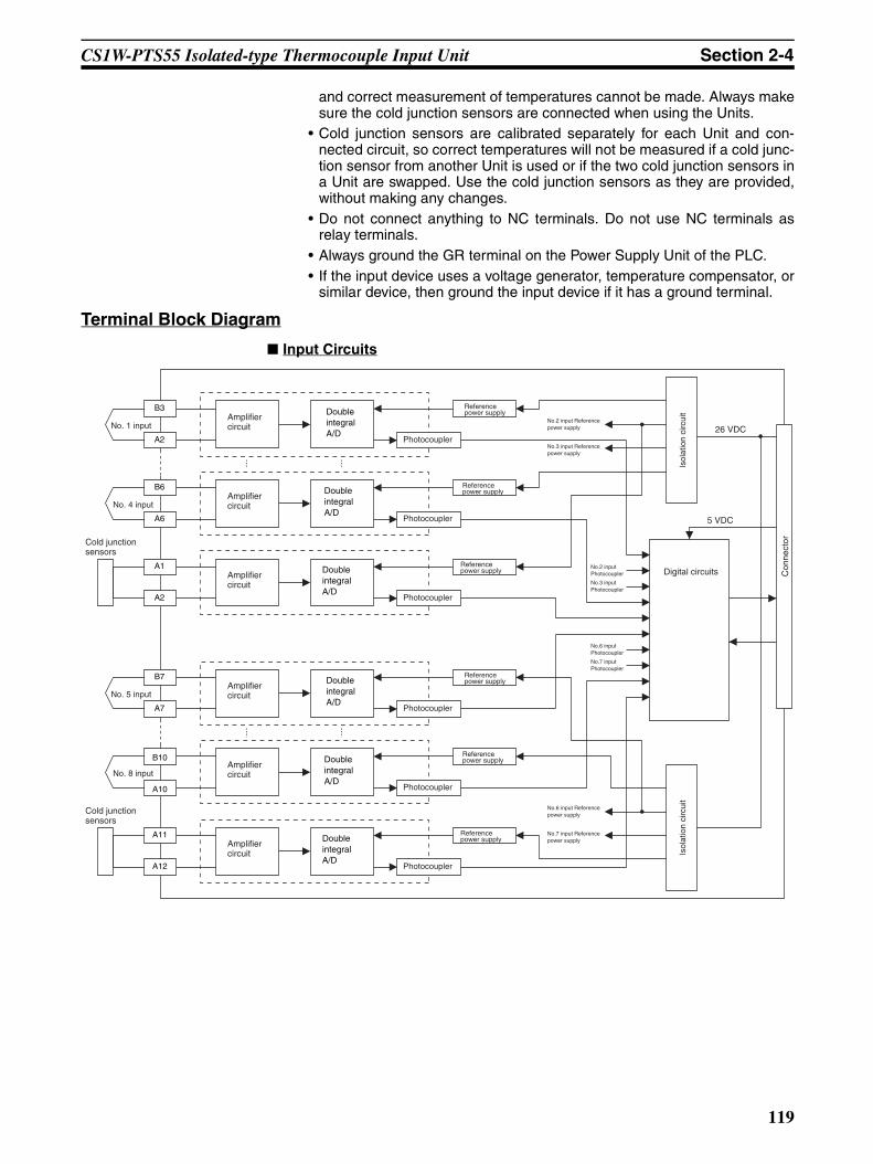
CS1W-PTS55 Isolated-type Thermocouple Input Unit Section 2-4
and correct measurement of temperatures cannot be made. Always makesure the cold junction sensors are connected when using the Units.
• Cold junction sensors are calibrated separately for each Unit and con-nected circuit, so correct temperatures will not be measured if a cold junc-tion sensor from another Unit is used or if the two cold junction sensors ina Unit are swapped. Use the cold junction sensors as they are provided,without making any changes.
• Do not connect anything to NC terminals. Do not use NC terminals asrelay terminals.
• Always ground the GR terminal on the Power Supply Unit of the PLC.• If the input device uses a voltage generator, temperature compensator, or
similar device, then ground the input device if it has a ground terminal.
Terminal Block Diagram
Input Circuits
5 VDC
Con
nect
or
Isol
atio
n ci
rcui
t
Digital circuitsReference power supply
Cold junction sensors
Double integral A/D
Amplifier circuit
Photocoupler
A1
A2
No. 4 inputAmplifier circuit
Photocoupler
B6
A6
Double integral A/D
Reference power supply
No. 1 inputAmplifier circuit
Photocoupler
B3
A2
Double integral A/D
Reference power supply
Reference power supply
Cold junction sensors
Double integral A/D
Amplifier circuit
Photocoupler
A11
A12
No. 8 inputAmplifier circuit
Photocoupler
B10
A10
Double integral A/D
Reference power supply
No. 5 inputAmplifier circuit
Photocoupler
B7
A7
Double integral A/D
Reference power supply
Isol
atio
n ci
rcui
t
No.2 input Reference power supply
No.3 input Reference power supply
No.2 input Photocoupler
No.3 input Photocoupler
No.6 input Photocoupler
No.7 input Photocoupler
No.6 input Reference power supply
No.7 input Reference power supply
26 VDC
119

CS1W-PTS55 Isolated-type Thermocouple Input Unit Section 2-4
Error Processing
Conversion Data Does Not Change.
Values are Not Converted as Intended.
Converted Values are Unstable.
Probable cause Remedy
The gain for span adjustment is set to 0.
Set the gain for span adjustment to a value other than 0.
The sensor type, input range, or process value scaling is not set correctly.
Check and correct the settings.
An input device is malfunctioning, input wiring is faulty, or wiring is disconnected.
Check whether the input voltage or current has changed. Check for faulty or disconnected wir-ing. Check whether a sensor error has been detected in the I/O Area.
Probable cause Remedy
The sensor type is not set cor-rectly.
Check and correct the settings.
The zero/span adjustment data is incorrect.
Check and correct the zero/span adjustment set-tings.
Cold junction compensation is not operating.
Check the Cold Junction Error Flag.
A compensation conductor has not been used or a different com-pensation conductor is used.
Use the correct compensation conductor for the thermocouple.
Incorrect input wiring (incorrect thermocouple or compensation conductor polarity.)
Correct the input wiring.
Thermocouple lead or compensat-ing conductor is too long and mea-surements are being affected by conductor resistance.
Use a thicker compensating conductor.Change the wiring position and shorten the com-pensating conductor.
The terminal block temperature is not uniform due to radiated heat from peripheral devices.
Mount the unit in a position unaffected by radi-ated heat.
Probable cause Remedy
Input signals are being affected by external noise.
Change the connection paths of the input signal lines. (Separate them from sources of noise or use shielded cable.)
Insert a 0.01 to 0.1 µF ceramic capacitor between the positive (+) and negative (−) input terminals.
An airflow is hitting the Unit termi-nal block.
Move the terminal block to a position unaffected by airflow.
120
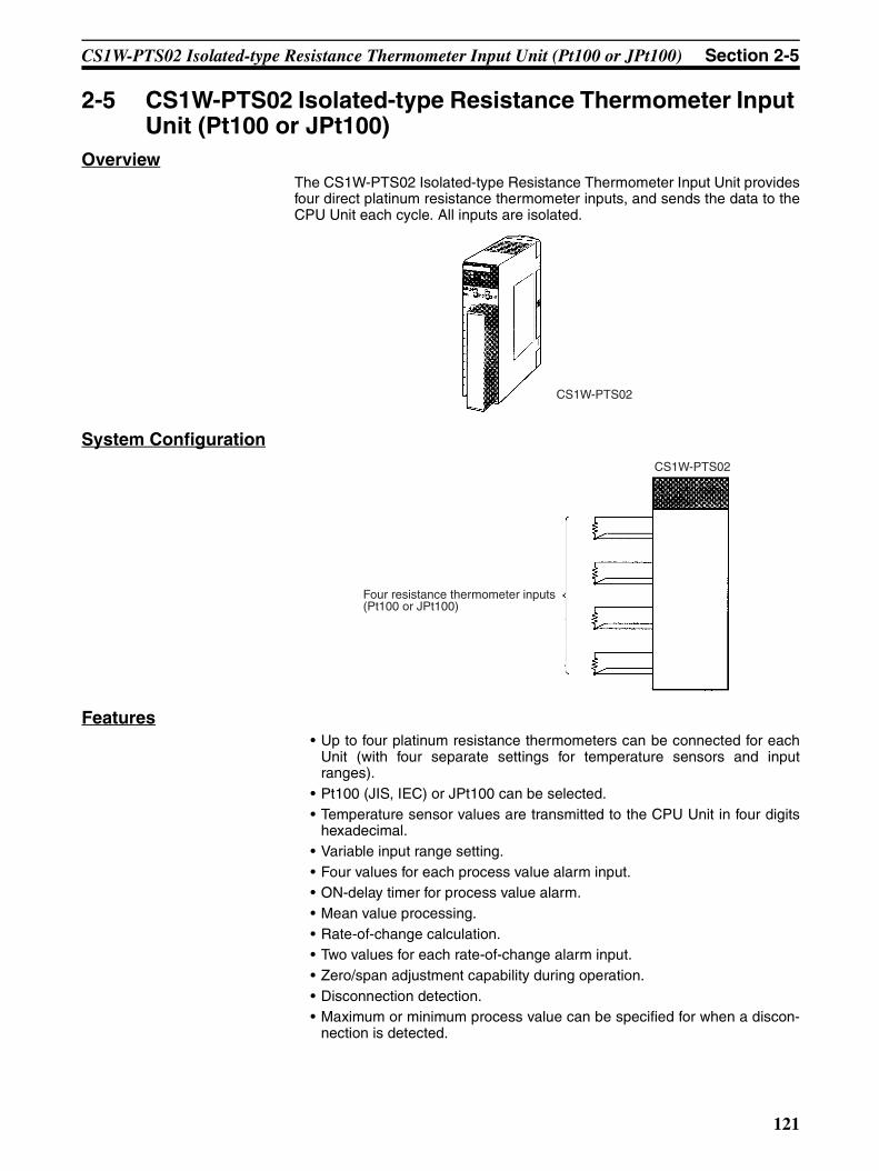
CS1W-PTS02 Isolated-type Resistance Thermometer Input Unit (Pt100 or JPt100) Section 2-5
2-5 CS1W-PTS02 Isolated-type Resistance Thermometer Input Unit (Pt100 or JPt100)
OverviewThe CS1W-PTS02 Isolated-type Resistance Thermometer Input Unit providesfour direct platinum resistance thermometer inputs, and sends the data to theCPU Unit each cycle. All inputs are isolated.
System Configuration
Features• Up to four platinum resistance thermometers can be connected for each
Unit (with four separate settings for temperature sensors and inputranges).
• Pt100 (JIS, IEC) or JPt100 can be selected.• Temperature sensor values are transmitted to the CPU Unit in four digits
hexadecimal.• Variable input range setting.• Four values for each process value alarm input.• ON-delay timer for process value alarm.• Mean value processing.• Rate-of-change calculation.• Two values for each rate-of-change alarm input.• Zero/span adjustment capability during operation.• Disconnection detection.• Maximum or minimum process value can be specified for when a discon-
nection is detected.
CS1W-PTS02
CS1W-PTS02
Four resistance thermometer inputs (Pt100 or JPt100)
121

CS1W-PTS02 Isolated-type Resistance Thermometer Input Unit (Pt100 or JPt100) Section 2-5
Model InformationUnit classification Model number Inputs Temperature sensor types
CS-series Special I/O Unit CS1W-PTS02 4 Platinum resistance thermometer Pt100 (JIS, IEC) or JPt100.
122

CS1W-PTS02 Isolated-type Resistance Thermometer Input Unit (Pt100 or JPt100) Section 2-5
Block Diagram (Order of Processing)The processing for the four inputs is as shown in the following diagram.
CPU Unit CIO Area
Process value Process value alarm Rate-of-change value Rate-of-change alarmInput disconnection alarm
Isolated-type Resistance Thermometer Input Unit
Process value alarm Rate-of-change alarm
Output limit: −15% to +115%
Rate-of-change calculation and scaling
+115% or −15% when input disconnection is detected
Output limit: −15% to +115%
Zero/span adjustment
Process value scaling
Input calculationsResistance thermometer typeInput range
A/D conversion, moving average
Resistance thermometer
Input disconnection check
HH, H, L, LL H, L
I/O refresh
123

CS1W-PTS02 Isolated-type Resistance Thermometer Input Unit (Pt100 or JPt100) Section 2-5
SpecificationsItem Specifications
Model CS1W-PTS02
Applicable PLC CS Series
Unit classification CS-series Special I/O Unit
Mounting position CS-series CPU Rack or CS-series Expansion Rack (Cannot be mounted to C200H Expansion I/O Rack or SYSMAC BUS Remote I/O Slave Rack.)
Maximum number of Units 80 (within the allowable current consumption and power consumption range)
Unit numbers 00 to 95 (Cannot duplicate Special I/O Unit numbers.)
Areas for data exchange with CPU Unit
Special I/O Unit Area
10 words/Unit
Resistance Thermometer Input Unit to CPU Unit:All process values, process value alarms (LL, L, H, HH), rate-of-change values, rate-of-change alarms (L, H), disconnection alarms, cold junction sensor errors
DM Area words allocated to Special I/O Units
100 words/UnitCPU Unit to Resistance Thermometer Input Unit:Temperature sensor type, input range (user set), scaling of process value data to be stored in allocated words in CIO area, number of items for moving average, process value alarm setting (LL, L, H, HH), rate-of-change alarm setting (L, H), zero/span adjustment value, etc.
Number of temperature sensor inputs
4
Temperature sensor types Pt100 (JIS, IEC) or JPt100 Sensor type, input range, and scaling to industrial units are separate for each of the 4 inputs.Note Sensor type, input range, and scal-
ing to industrial units are set in the DM Area.
Input ranges The input range can be set within any of the measurable input ranges shown in Table 1 (below).Note Internally, inputs are processed in
five ranges (refer to Table 2 below), so accuracy and resolution accord with these internal ranges.
Example:Sensor type: Pt100; input range: 0 to 500°C; industrial unit scaling: 0.0 to 500°C. DM Area settings are as follows:
Sensor type: 0 (0000 hex)Input signal maximum: 5000 (1388 hex)Input signal minimum: 0 (0000 hex)Industrial unit maximum value stored: 500 (01F4 hex)Industrial unit minimum value stored: 0 (0000 hex)
Scaling in industrial units Data to be stored in the allocated words in the CIO area must be scaled (individually for each of 4 inputs, with the minimum and maximum values set). Data can be stored at 0% to 100%.
Data storage in the CIO Area The value derived from carrying out the following processing in order of the actual process data in the input range is stored in four digits hexadecimal (binary values) in the allocated words in the CIO Area.1) Mean value processing → 2) Scaling → 3) Zero/span adjustment → 4) Output lim-its
Accuracy (25°C) The greater of the following: ±0.1% (of internal range full span) or 0.1°CAs shown in the following equation, the accuracy depends on the ratio of the selected internal range (0 to 4) span to the set input range span.
Temperature coefficient ±0.015% /°C, for any of internal range numbers 0 to 4.
Resolution 1/4,096 (of internal range full span)As shown in the following equation, the resolution depends on the ratio of the selected internal range (0 to 4) span to the set input range span.
Sensing method 3-wire method
Allowable lead wire resistance 20 Ω max. per wire
Accuracy = ±0.1% x Internal range span
Set input range spanor 0.1°C, whichever is greater.
Resolution =1
4096Internal range span
Set input range spanx
124

CS1W-PTS02 Isolated-type Resistance Thermometer Input Unit (Pt100 or JPt100) Section 2-5
Sensor Type and Input RangeThe resistance thermometer type and input range are set in the allocatedwords in the DM Area for every four inputs. The input range can be set any-where within the measurable input ranges shown in Table 1.
Table 1: Measurable Input Ranges
Note Set the input range in the DM Area within this range.
Internally inputs are processed in five progressive ranges (numbers 0 to 4), asshown in the following table.
Table 2: Internal Ranges
Input detection current 0.25 mA
Warmup time 10 min
Response time 0.5 s (travel time from input 0% to 90%, for step input)
Conversion period 100 ms/4 inputs
Maximum time to store data in CPU Unit
Conversion period + one CPU Unit cycle
Disconnection detection Detects disconnections at each input and turns ON the Disconnection Detection Flag.Hardware detection time: Approx. 1 sThe process value overrange direction for when a disconnection occurs can be speci-fied. (High: 115% of set input range; low: –15% of set input range)
Function Mean value pro-cessing (input filter)
Calculates the moving average for the specified number of process values (1 to 16), and stores that value in the CIO Area as the process value.
Process value alarm
Process value 4-point alarm (HH, H, LL, L), alarm hysteresis, and ON-delay timer (0 to 60 s) are available.
Rate-of-change calculation
Calculates the amount of change per comparison time interval (1 to 16 s).
Rate-of-change alarm
Rate-of-change 2-point alarm (H, L), alarm hysteresis (shared with process value alarm), and ON-delay timer (0 to 60 s, shared with process value alarm) are available.
Isolation Between temperature inputs and between input terminals and PLC signals: Isolation by transformer
Insulation resistance 20 MΩ (at 500 V DC) between inputs
Dielectric strength Between inputs: 1,000 V AC, at 50/60 Hz, for 1 min, leakage current 10 mA max.
External connections Terminal block (detachable)
Unit number settings Set by rotary switches on front panel, from 0 to 95.
Indicators Three LED indicators on front panel (for normal operation, errors detected at the Resistance Thermometer Input Unit, and errors related to the CPU Unit).
Front panel connector Sensor input connector terminal block (detachable)
Effect on CPU Unit cycle time 0.3 ms
Current consumption 5 V DC at 150 mA max., 26 V DC at 150 mA max.
Dimensions 35 × 130 × 126 mm (W × H × D)
Note The height including the Backplane is 145 mm.
Weight 450 g max.
Standard accessories None
Item Specifications
Sensor type DM Area setting Measurable input range (See note.)
Pt100 0 –200 to 850°CJPt100 1 –200 to 500°C
Internal range number Temperature range Span
0 –200 to 850°C 1,050°C1 –200 to 438°C 638°C2 –200 to 211°C 411°C
125

CS1W-PTS02 Isolated-type Resistance Thermometer Input Unit (Pt100 or JPt100) Section 2-5
Therefore, the accuracy and resolution are determined by the ratio of theselected internal range (0 to 4) span to the set input range span. For the inter-nal range, a larger number is selected when both the minimum and maximumvalues of the range fall within that next range.For example, suppose that the sensor type is Pt100 and the set input range is–100 to 400°C. Since both the minimum and maximum values fall within thelimits for internal range No. 1 (–200 to 438°C), that range will be selected.
Note With Resistance Thermometer Input Units, process values can be scaled(e.g., 0% to 100%) in industrial units for the set input range. It is possible toset the process value scaling higher than the resolution, but it will cause thevalues to be unstable.
DM Area Allocationsm = D20000 + unit number × 100 (unit number: 0 to 95)
3 –100 to 104°C 204°C4 –51 to 52°C 103°C
Internal range number Temperature range Span
DM Area address Data range Default Data contents
Input No. 1
Input No. 2
Input No. 3
Input No. 4
Decimal Hexadecimal
m 12345, 0 3039, 0000 hex 0000 hex Default block read commandSpecifies the direction of data transfer when the PLC is turned ON or the Unit is restarted for DM words m+2 to m+93.• 12345 (3039 hex): The data in words m+2 to
m+93 is transferred from the ResistanceThermometer Input Unit to the CPU Unit.When the transfer is completed, the valuewill become 0000 hex.
• Other than 12345 (3039 hex) (such as 0000hex): The data in the allocated words of DMArea is transferred from the CPU Unit to theResistance Thermometer Input Unit.
Setting Group 1 (continuously refreshed area): Parameters that are continuously refreshed during PLC operation (regardless of the CPU Unit’s operation mode)
Process value alarm settings
m + 2 m + 10 m + 18 m + 26 –32768 to 32767
8000 to FFFF hex, 0000 to 7FFF hex
4200 (1068 hex)
Process value HH (high high limit) alarm set-ting(Set at process value scaling value.)
m + 3 m + 11 m + 19 m + 27 –32768 to 32767
8000 to FFFF hex, 0000 to 7FFF hex
4000 (0FA0 hex)
Process value H (high limit) alarm setting(Set at process value scaling value.)
m + 4 m + 12 m + 20 m + 28 –32768 to 32767
8000 to FFFF hex, 0000 to 7FFF hex
0 (0000 hex)
Process value L (low limit) alarm setting(Set at process value scaling value.)
m + 5 m + 13 m + 21 m + 29 –32768 to 32767
8000 to FFFF hex, 0000 to 7FFF hex
–200 (FF38 hex)
Process value LL (low low limit) alarm setting(Set at process value scaling value.)
Rate-of-change value alarm settings
m + 6 m + 14 m + 22 m + 30 –32768 to 32767
8000 to FFFF hex, 0000 to 7FFF hex
4000 (0FA0 hex)
Rate-of-change value H (high limit) alarm set-ting(Set at rate-of-change scaling value.)
m + 7 m + 15 m + 23 m + 31 –32768 to 32767
8000 to FFFF hex, 0000 to 7FFF hex
0 (0000 hex)
Rate-of-change value L (low limit) alarm set-ting(Set at rate-of-change scaling value.)
Zero/span adjustment
m + 8 m + 16 m + 24 m + 32 0 to 32000 0000 to 7D00 hex 10000 (2710 hex)
Gain for span adjustment(set value x 0.0001)
m + 9 m + 17 m + 25 m + 33 –32000 to 32000
8300 to FFFF hex,0000 to 7D00 hex
0 (0000 hex)
Zero adjustment value(Set at process value scaling value.)
Setting Group 2 (initial settings area): Parameters that are transferred one time from the CPU Unit to the Resistance Thermometer Input Unit if word m contains other than 12345 when the PLC is turned ON or the Resistance Thermometer Input Unit is restarted.
m + 34 m + 49 m + 64 m + 79 0, 1 0000 to 0001 hex 0 (0000 hex)
Sensor type0: Pt100; 1: JPt100
Process value input range settings
126

CS1W-PTS02 Isolated-type Resistance Thermometer Input Unit (Pt100 or JPt100) Section 2-5
Note The ERC indicator on the Unit’s front panel will light if an out-of-range settingis made in either Setting Group 1 or 2. The offset from word m to the first wordcontaining the out-of-range error will be stored as the Address of Data RangeError in the DM Area in four digits hexadecimal. For more information, refer to1-6 Error Processing.
m + 35 m + 50 m + 65 m + 80 –32000 to 32000
8300 to FFFF hex, 0000 to 7D00 hex
4000 (0FA0 hex)
Maximum input signal value(set value x 0.1°C/°F)
m + 36 m + 51 m + 66 m + 81 –32000 to 32000
8300 to FFFF hex, 0000 to 7D00 hex
0 (0000 hex)
Minimum input signal value(set value x 0.1°C/°F)
m + 37 m + 52 m + 67 m + 82 0, 1 0000, 0001 hex 0 (0000 hex)
Unit0: °C, 1: °F
m + 38 m + 53 m + 68 m + 83 0, 1 0000, 0001 hex 0 (0000 hex)
Process value overrange direction at time of input disconnection0: High; 1: Low
Process value scaling
m + 39 m + 54 m + 69 m + 84 –32000 to 32000
8300 to FFFF hex, 0000 to 7D00 hex
4000 (0FA0 hex)
Value stored for maximum value in range (span)
m + 40 m + 55 m + 70 m + 85 –32000 to 32000
8300 to FFFF hex, 0000 to 7D00 hex
0 (0000 hex)
Value stored for minimum value in range (zero)
Alarm supplementary functions
m + 41 m + 56 m + 71 m + 86 0 to 32000 0000 to 7D00 hex 40 (0028 hex)
Alarm hysteresis(Set at process value scaling value. Shared with process value alarm and rate-of-change alarm.)
m + 42 m + 57 m + 72 m + 87 0 to 60 0000 to 003C hex 0 (0000 hex)
Alarm ON-delay time (Unit: s)(Shared with process value alarm and rate-of-change alarm.)
Rate-of-change function
m + 43 m + 58 m + 73 m + 88 –32000 to 32000
8300 to FFFF hex, 0000 to 7D00 hex
4000 (0FA0 hex)
Rate-of-change range setting
Maximum rate-of-change value (Process value industrial unit; comparison time interval)
m + 44 m + 59 m + 74 m + 89 –32000 to 32000
8300 to FFFF hex, 0000 to 7D00 hex
–4000 (F060 hex)
Minimum rate-of-change value (Process value industrial unit; comparison time interval)
m + 45 m + 60 m + 75 m + 90 1 to 16 0001 to 0010 hex 1 (0001 hex)
Rate-of-change comparison time interval (Unit: s)
m + 46 m + 61 m + 76 m + 91 –32000 to 32000
8300 to FFFF hex, 0000 to 7D00 hex
4000 (0FA0 hex)
Rate-of-change value scaling
Value stored for maximum value in range
m + 47 m + 62 m + 77 m + 92 –32000 to 32000
8300 to FFFF hex, 0000 to 7D00 hex
0 (0000 hex)
Value stored for minimum value in range
Mean value processing function
m + 48 m + 63 m + 78 m + 93 1 to 16 0001 to 0010 hex 4 (0004 hex)
Number of process values for calculating mov-ing average for mean value processing
Storage parameter
m + 94 m + 95 m + 96 m + 97 0 to 93 0000 to 005D hex 0 (0000 hex)
Address of Data Range Error (See note.)
DM Area address Data range Default Data contents
Input No. 1
Input No. 2
Input No. 3
Input No. 4
Decimal Hexadecimal
127

CS1W-PTS02 Isolated-type Resistance Thermometer Input Unit (Pt100 or JPt100) Section 2-5
CIO Area Allocationsn = 2000 + unit number × 10 (unit number: 0 to 95)
Direction Word Bit Name Data range Contents
Resistance Thermome-ter Input Unit to CPU Unit
n 00 Input No. 1 Process value LL (low low limit) alarm
0, 1 0: Process value > Set value
1: Process value ≤ Set value
01 Process value L (low limit) alarm
0, 1
02 Process value H (high limit) alarm
0, 1 0: Process value < Set value1: Process value ≥ Set value
03 Process value HH (high high limit) alarm
0, 1
04 Input No. 2 Process value LL (low low limit) alarm
0, 1 Same as for input No. 1.
05 Process value L (low limit) alarm
0, 1
06 Process value H (high limit) alarm
0, 1
07 Process value HH (high high limit) alarm
0, 1
08 Input No. 3 Process value LL (low low limit) alarm
0, 1 Same as for input No. 1.
09 Process value L (low limit) alarm
0, 1
10 Process value H (high limit) alarm
0, 1
11 Process value HH (high high limit) alarm
0, 1
12 Input No. 4 Process value LL (low low limit) alarm
0, 1 Same as for input No. 1.
13 Process value L (low limit) alarm
0, 1
14 Process value H (high limit) alarm
0, 1
15 Process value HH (high high limit) alarm
0, 1
128
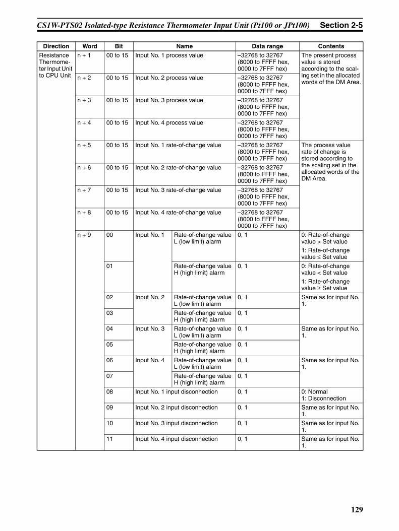
CS1W-PTS02 Isolated-type Resistance Thermometer Input Unit (Pt100 or JPt100) Section 2-5
Resistance Thermome-ter Input Unit to CPU Unit
n + 1 00 to 15 Input No. 1 process value –32768 to 32767 (8000 to FFFF hex, 0000 to 7FFF hex)
The present process value is stored according to the scal-ing set in the allocated words of the DM Area.
n + 2 00 to 15 Input No. 2 process value –32768 to 32767 (8000 to FFFF hex, 0000 to 7FFF hex)
n + 3 00 to 15 Input No. 3 process value –32768 to 32767 (8000 to FFFF hex, 0000 to 7FFF hex)
n + 4 00 to 15 Input No. 4 process value –32768 to 32767 (8000 to FFFF hex, 0000 to 7FFF hex)
n + 5 00 to 15 Input No. 1 rate-of-change value –32768 to 32767 (8000 to FFFF hex, 0000 to 7FFF hex)
The process value rate of change is stored according to the scaling set in the allocated words of the DM Area.
n + 6 00 to 15 Input No. 2 rate-of-change value –32768 to 32767 (8000 to FFFF hex, 0000 to 7FFF hex)
n + 7 00 to 15 Input No. 3 rate-of-change value –32768 to 32767 (8000 to FFFF hex, 0000 to 7FFF hex)
n + 8 00 to 15 Input No. 4 rate-of-change value –32768 to 32767 (8000 to FFFF hex, 0000 to 7FFF hex)
n + 9 00 Input No. 1 Rate-of-change value L (low limit) alarm
0, 1 0: Rate-of-change value > Set value1: Rate-of-change value ≤ Set value
01 Rate-of-change value H (high limit) alarm
0, 1 0: Rate-of-change value < Set value
1: Rate-of-change value ≥ Set value
02 Input No. 2 Rate-of-change value L (low limit) alarm
0, 1 Same as for input No. 1.
03 Rate-of-change value H (high limit) alarm
0, 1
04 Input No. 3 Rate-of-change value L (low limit) alarm
0, 1 Same as for input No. 1.
05 Rate-of-change value H (high limit) alarm
0, 1
06 Input No. 4 Rate-of-change value L (low limit) alarm
0, 1 Same as for input No. 1.
07 Rate-of-change value H (high limit) alarm
0, 1
08 Input No. 1 input disconnection 0, 1 0: Normal1: Disconnection
09 Input No. 2 input disconnection 0, 1 Same as for input No. 1.
10 Input No. 3 input disconnection 0, 1 Same as for input No. 1.
11 Input No. 4 input disconnection 0, 1 Same as for input No. 1.
Direction Word Bit Name Data range Contents
129
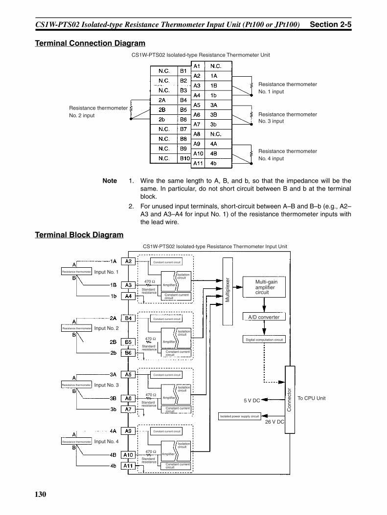
CS1W-PTS02 Isolated-type Resistance Thermometer Input Unit (Pt100 or JPt100) Section 2-5
Terminal Connection Diagram
Note 1. Wire the same length to A, B, and b, so that the impedance will be thesame. In particular, do not short circuit between B and b at the terminalblock.
2. For unused input terminals, short-circuit between A–B and B–b (e.g., A2–A3 and A3–A4 for input No. 1) of the resistance thermometer inputs withthe lead wire.
Terminal Block Diagram
CS1W-PTS02 Isolated-type Resistance Thermometer Unit
No. 2 input
No. 1 input
No. 3 input
No. 4 input
Resistance thermometer
Resistance thermometer
Resistance thermometer
Resistance thermometer
CS1W-PTS02 Isolated-type Resistance Thermometer Input Unit
Isolation circuit
Multi-gain amplifier circuit
A/D converter
Digital computation circuit
5 V DC
26 V DCIsolated power supply circuit
To CPU Unit
Resistance thermometer
Resistance thermometer
Resistance thermometer
Resistance thermometer
Constant current circuit
Standard resistance
Input No. 2
Input No. 1
Input No. 3
Input No. 4
Amplifier
Isolation circuit
Constant current circuit
Amplifier
Isolation circuit
Constant current circuit
Amplifier
Isolation circuit
Constant current circuit
Amplifier
Mul
tiple
xer
Con
nect
orConstant current circuit
Standard resistance
Constant current circuit
Standard resistance
Constant current circuit
Standard resistance
Constant current circuit
470 Ω
470 Ω
470 Ω
470 Ω
130

CS1W-PTS02 Isolated-type Resistance Thermometer Input Unit (Pt100 or JPt100) Section 2-5
Error Processing
Conversion Data Does Not Change.
Values are Not Converted as Intended.
Converted Values are Unstable.
Probable cause Remedy
The gain for span adjustment is set to 0.
Set the gain for span adjustment to a value other than 0.
The minimum and maximum val-ues for process value scaling are either the same or are set extremely low.
Set the minimum and maximum values correctly.
The sensor type, input range, or process value scaling is not set correctly.
Check and correct the settings.
An input device is malfunctioning, input wiring is faulty, or wiring is disconnected.
Check whether the input voltage or current has changed. Check for faulty or discon-nected wiring. Check whether a wiring disconnection has been detected in the I/O Area.
Probable cause Remedy
The sensor type, input range, or process value scaling is not set correctly.
Check and correct the settings.
The zero/span adjustment data is incorrect.
Check and correct the zero/span adjustment settings.
The resistance thermometer input wiring is faulty.
Correct the input wiring.
Probable cause Remedy
Input signals are being affected by external noise.
Change the connection paths of the input signal lines. (Separate them from sources of noise or use shielded cable.)
Increase the number of values for calculating the moving average in mean value pro-cessing.
The process value scaling value is greater than the Unit’s resolu-tion.
Reduce the process value scaling value.
The input signal range setting is too small.
Match the input signal range to the internal ranges.
131

CS1W-PTS03 Isolated-type Resistance Thermometer Input Unit (Ni508.4) Section 2-6
2-6 CS1W-PTS03 Isolated-type Resistance Thermometer Input Unit (Ni508.4)
OverviewThe CS1W-PTS03 Isolated-type Resistance Thermometer Input Unit providesfour direct Ni thermometer inputs, and sends the data to the CPU Unit eachcycle. All inputs are isolated.
System Configuration
Features• Up to four Ni resistance thermometers can be connected for each Unit
(with four separate input ranges).• Temperature sensor values are sent to the CPU Unit in four digits hexa-
decimal.• Variable input range setting.• Four values for each process value alarm input.• ON-delay timer for process value alarm.• Mean value processing.• Rate-of-change calculation.• Two values for each rate-of-change alarm input.• Zero/span adjustment capability during operation.• Disconnection detection.• Maximum or minimum process value can be specified for when a discon-
nection is detected.
CS1W-PTS03
Four resistance thermometer inputs (Ni508.4 Ω)
CS1W-PTS03
132
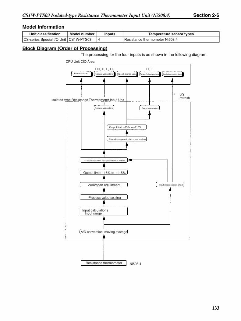
CS1W-PTS03 Isolated-type Resistance Thermometer Input Unit (Ni508.4) Section 2-6
Model Information
Block Diagram (Order of Processing)The processing for the four inputs is as shown in the following diagram.
Unit classification Model number Inputs Temperature sensor types
CS-series Special I/O Unit CS1W-PTS03 4 Resistance thermometer Ni508.4
CPU Unit CIO Area
Process value Process value alarm Rate-of-change value Rate-of-change alarm Input disconnection alarm
Isolated-type Resistance Thermometer Input Unit
Process value alarm Rate-of-change alarm
Output limit: −15% to +115%
Rate-of-change calculation and scaling
+115% or −15% when input disconnection is detected
Output limit: −15% to +115%
Zero/span adjustment
Process value scaling
Input calculationsInput range
A/D conversion, moving average
Resistance thermometer
Input disconnection check
HH, H, L, LL H, L
I/O refresh
Ni508.4
133

CS1W-PTS03 Isolated-type Resistance Thermometer Input Unit (Ni508.4) Section 2-6
SpecificationsItem Specifications
Model CS1W-PTS03
Applicable PLC CS Series
Unit classification CS-series Special I/O Unit
Mounting position CS-series CPU Rack or CS-series Expansion Rack (Cannot be mounted to C200H Expansion I/O Rack or SYSMAC BUS Remote I/O Slave Rack.)
Maximum number of Units 80 (within the allowable current consumption and power consumption range)
Unit numbers 00 to 95 (Cannot duplicate Special I/O Unit numbers.)
Areas for data exchange with CPU Unit
Special I/O Unit Area
10 words/Unit
Resistance Thermometer Input Unit to CPU Unit:All process values, process value alarms (LL, L, H, HH), rate-of-change values, rate-of-change alarms (L, H), disconnection alarms
DM Area words allocated to Special I/O Units
100 words/UnitCPU Unit to Resistance Thermometer Input Unit:Temperature sensor type, input range (user set), scaling of process value data to be stored in allocated words in CIO area, number of items for moving average, process value alarm setting (LL, L, H, HH), rate-of-change alarm setting (L, H), zero/span adjustment value, etc.
Number of temperature sensor inputs
4
Temperature sensor types Ni508.4 Input range and scaling to industrial units are separate for each of the 4 inputs.
Note Sensor type, input range, and scal-ing to industrial units are set in the DM Area.
Input ranges The input range can be set within a range of –50 to 150°C (variable setting).
Note Internally, inputs are processed in the above range (refer to Table 2 below), so accuracy and resolution accord with this internal range.
Example:Input range: –50 to 100°C; industrial unit scaling: –50.0 to 100.0°C. DM Area set-tings are as follows:Input signal maximum: 1000 (03E8 hex)Input signal minimum: –500 (FE0C hex)Industrial unit maximum value stored: 1000 (03E8 hex)Industrial unit minimum value stored: –500 (FE0C hex)
Scaling in industrial units Data to be stored in the allocated words in the CIO area must be scaled (with the minimum and maximum values set). Data can be stored at 0% to 100%.
Data storage in the CIO Area The value derived from carrying out the following processing in order of the actual process data in the input range is stored in four digits hexadecimal (binary values) in the allocated words in the CIO Area.1) Mean value processing → 2) Scaling → 3) Zero/span adjustment → 4) Output lim-its
Accuracy (25°C) The greater of the following: ±0.2% (of internal range full span) or 0.2°CAs shown in the following equation, the accuracy depends on the ratio of the selected internal range (0 to 4) span to the set input range span.
Temperature coefficient ±0.015% /°C, for any of internal range numbers 0 to 4.
Resolution 1/4,096 (of internal range full span)As shown in the following equation, the resolution depends on the ratio of the internal range span to the set input range span.
Sensing method 3-wire method
Allowable lead wire resistance 20 Ω max. per wire
Input detection current 0.25 mA
Warmup time 10 min
Accuracy = ±0.1% x Internal range span
Set input range spanor 0.2°C, whichever is greater.
Resolution =1
4096Internal range spanSet input range spanx
134

CS1W-PTS03 Isolated-type Resistance Thermometer Input Unit (Ni508.4) Section 2-6
Sensor Type and Input RangeThe input range is set in the allocated words in the DM Area for every fourinputs. It can be set anywhere within the measurable input range shown inTable 1.
Measurable Input Range
Note Set the input range in the DM Area within this range.
Even if the input range is set more narrowly than the range of –50 to 150°C,internally inputs will be processed according to the internal range shown inthe following table.
Internal range
Therefore, the accuracy and resolution are determined by the ratio of theinternal range span to the set input range span.Example: Even if the set input range is –50 to 100°C, internally inputs will beprocessed according to the internal range of –50 to 150°C.
Response time 0.5 s (travel time from input 0% to 90%, for step input)
Conversion period 100 ms/4 inputs
Maximum time to store data in CPU Unit
Conversion period + one CPU Unit cycle
Disconnection detection Detects disconnections at each input and turns ON the Disconnection Detection Flag.Hardware detection time: Approx. 1 sThe process value high/low direction for when a disconnection occurs can be speci-fied. (High: 115% of set input range; low: –15% of set input range)
Function Mean value pro-cessing (input filter)
Calculates the moving average for the specified number of process values (1 to 16), and stores that value in the CIO Area as the process value.
Process value alarm
Process value 4-point alarm (HH, H, LL, L), alarm hysteresis, and ON-delay timer (0 to 60 s) are available.
Rate-of-change calculation
Calculates the amount of change per comparison time interval (1 to 16 s).
Rate-of-change alarm
Rate-of-change 2-point alarm (H, L), alarm hysteresis (shared with process value alarm), and ON-delay timer (0 to 60 s, shared with process value alarm) are available.
Isolation Between temperature inputs and between input terminals and PLC signals: Isolation by transformer
Insulation resistance 20 MΩ (at 500 V DC) between inputs
Dielectric strength Between inputs: 1,000 V AC, at 50/60 Hz, for 1 min, leakage current 10 mA max.
External connections Terminal block (detachable)
Unit number settings Set by rotary switches on front panel, from 0 to 95.
Indicators Three LED indicators on front panel (for normal operation, errors detected at the Resistance Thermometer Input Unit, and errors related to the CPU Unit).
Front panel connector Sensor input connector terminal block (detachable)
Effect on CPU Unit cycle time 0.3 ms
Current consumption 5 V DC at 150 mA max., 26 V DC at 150 mA max.
Dimensions 35 × 130 × 126 mm (W × H × D)
Note The height including the Backplane is 145 mm.
Weight 450 g max.
Standard accessories None
Item Specifications
Sensor type Measurable Input range (See note.)
Ni508.4 –50 to 150°C
Internal range temperatures Internal range span
–50 to 150°C 200°C
135
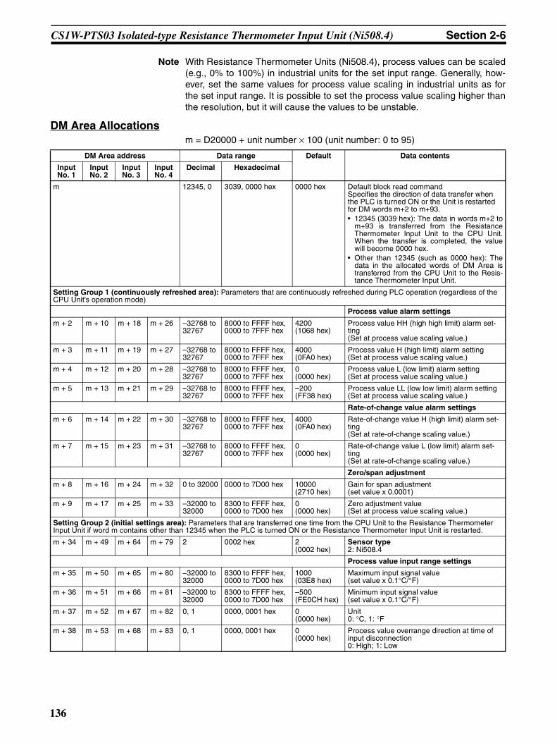
CS1W-PTS03 Isolated-type Resistance Thermometer Input Unit (Ni508.4) Section 2-6
Note With Resistance Thermometer Units (Ni508.4), process values can be scaled(e.g., 0% to 100%) in industrial units for the set input range. Generally, how-ever, set the same values for process value scaling in industrial units as forthe set input range. It is possible to set the process value scaling higher thanthe resolution, but it will cause the values to be unstable.
DM Area Allocationsm = D20000 + unit number × 100 (unit number: 0 to 95)
DM Area address Data range Default Data contents
Input No. 1
Input No. 2
Input No. 3
Input No. 4
Decimal Hexadecimal
m 12345, 0 3039, 0000 hex 0000 hex Default block read commandSpecifies the direction of data transfer when the PLC is turned ON or the Unit is restarted for DM words m+2 to m+93.• 12345 (3039 hex): The data in words m+2 to
m+93 is transferred from the ResistanceThermometer Input Unit to the CPU Unit.When the transfer is completed, the valuewill become 0000 hex.
• Other than 12345 (such as 0000 hex): Thedata in the allocated words of DM Area istransferred from the CPU Unit to the Resis-tance Thermometer Input Unit.
Setting Group 1 (continuously refreshed area): Parameters that are continuously refreshed during PLC operation (regardless of the CPU Unit’s operation mode)
Process value alarm settings
m + 2 m + 10 m + 18 m + 26 –32768 to 32767
8000 to FFFF hex, 0000 to 7FFF hex
4200 (1068 hex)
Process value HH (high high limit) alarm set-ting(Set at process value scaling value.)
m + 3 m + 11 m + 19 m + 27 –32768 to 32767
8000 to FFFF hex, 0000 to 7FFF hex
4000 (0FA0 hex)
Process value H (high limit) alarm setting(Set at process value scaling value.)
m + 4 m + 12 m + 20 m + 28 –32768 to 32767
8000 to FFFF hex, 0000 to 7FFF hex
0 (0000 hex)
Process value L (low limit) alarm setting(Set at process value scaling value.)
m + 5 m + 13 m + 21 m + 29 –32768 to 32767
8000 to FFFF hex, 0000 to 7FFF hex
–200 (FF38 hex)
Process value LL (low low limit) alarm setting(Set at process value scaling value.)
Rate-of-change value alarm settings
m + 6 m + 14 m + 22 m + 30 –32768 to 32767
8000 to FFFF hex, 0000 to 7FFF hex
4000 (0FA0 hex)
Rate-of-change value H (high limit) alarm set-ting(Set at rate-of-change scaling value.)
m + 7 m + 15 m + 23 m + 31 –32768 to 32767
8000 to FFFF hex, 0000 to 7FFF hex
0 (0000 hex)
Rate-of-change value L (low limit) alarm set-ting(Set at rate-of-change scaling value.)
Zero/span adjustment
m + 8 m + 16 m + 24 m + 32 0 to 32000 0000 to 7D00 hex 10000 (2710 hex)
Gain for span adjustment(set value x 0.0001)
m + 9 m + 17 m + 25 m + 33 –32000 to 32000
8300 to FFFF hex,0000 to 7D00 hex
0 (0000 hex)
Zero adjustment value(Set at process value scaling value.)
Setting Group 2 (initial settings area): Parameters that are transferred one time from the CPU Unit to the Resistance Thermometer Input Unit if word m contains other than 12345 when the PLC is turned ON or the Resistance Thermometer Input Unit is restarted.
m + 34 m + 49 m + 64 m + 79 2 0002 hex 2 (0002 hex)
Sensor type2: Ni508.4
Process value input range settings
m + 35 m + 50 m + 65 m + 80 –32000 to 32000
8300 to FFFF hex, 0000 to 7D00 hex
1000 (03E8 hex)
Maximum input signal value(set value x 0.1°C/°F)
m + 36 m + 51 m + 66 m + 81 –32000 to 32000
8300 to FFFF hex, 0000 to 7D00 hex
–500 (FE0CH hex)
Minimum input signal value(set value x 0.1°C/°F)
m + 37 m + 52 m + 67 m + 82 0, 1 0000, 0001 hex 0 (0000 hex)
Unit0: °C, 1: °F
m + 38 m + 53 m + 68 m + 83 0, 1 0000, 0001 hex 0 (0000 hex)
Process value overrange direction at time of input disconnection0: High; 1: Low
136

CS1W-PTS03 Isolated-type Resistance Thermometer Input Unit (Ni508.4) Section 2-6
Note The ERC indicator on the Unit’s front panel will light if an out-of-range settingis made in either Setting Group 1 or 2. The offset from word m to the first wordcontaining the out-of-range error will be stored as the Address of Data RangeError in the DM Area in four digits hexadecimal. For more information, refer to1-6 Error Processing.
Process value scaling
m + 39 m + 54 m + 69 m + 84 –32000 to 32000
8300 to FFFF hex, 0000 to 7D00 hex
4000 (0FA0 hex)
Value stored for maximum value in range (span)
m + 40 m + 55 m + 70 m + 85 –32000 to 32000
8300 to FFFF hex, 0000 to 7D00 hex
0 (0000 hex)
Value stored for minimum value in range (zero)
Alarm supplementary functions
m + 41 m + 56 m + 71 m + 86 0 to 32000 0000 to 7D00 hex 40 (0028 hex)
Alarm hysteresis(Set at process value scaling value. Shared with process value alarm and rate-of-change alarm.)
m + 42 m + 57 m + 72 m + 87 0 to 60 0000 to 003C hex 0 (0000 hex)
Alarm ON-delay time (Unit: s)(Shared with process value alarm and rate-of-change alarm.)
Rate-of-change function
m + 43 m + 58 m + 73 m + 88 –32000 to 32000
8300 to FFFF hex, 0000 to 7D00 hex
4000 (0FA0 hex)
Rate-of-change range setting
Maximum rate-of-change value (Process value industrial unit; comparison time interval)
m + 44 m + 59 m + 74 m + 89 –32000 to 32000
8300 to FFFF hex, 0000 to 7D00 hex
–4000 (F060 hex)
Minimum rate-of-change value (Process value industrial unit; comparison time interval)
m + 45 m + 60 m + 75 m + 90 1 to 16 0001 to 0010 hex 1 (0001 hex)
Rate-of-change comparison time interval (Unit: s)
m + 46 m + 61 m + 76 m + 91 –32000 to 32000
8300 to FFFF hex, 0000 to 7D00 hex
4000 (0FA0 hex)
Rate-of-change value scaling
Value stored for maximum value in range
m + 47 m + 62 m + 77 m + 92 –32000 to 32000
8300 to FFFF hex, 0000 to 7D00 hex
0 (0000 hex)
Value stored for minimum value in range
Mean value processing function
m + 48 m + 63 m + 78 m + 93 1 to 16 0001 to 0010 hex 4 (0004 hex)
Number of process values for calculating mov-ing average for mean value processing
Storage parameter
m + 94 m + 95 m + 96 m + 97 0 to 93 0000 to 005D hex 0 (0000 hex)
Address of Data Range Error (See note.)
DM Area address Data range Default Data contents
Input No. 1
Input No. 2
Input No. 3
Input No. 4
Decimal Hexadecimal
137

CS1W-PTS03 Isolated-type Resistance Thermometer Input Unit (Ni508.4) Section 2-6
CIO Area Allocationsn = 2000 + unit number × 10 (unit number: 0 to 95)
Direction Word Bit Name Data range Contents
Resistance Thermo-meter Input Unit to CPU Unit
n 00 Input No. 1 Process value LL (low low limit) alarm
0, 1 0: Process value > Set value
1: Process value ≤ Set value
01 Process value L (low limit) alarm
0, 1
02 Process value H (high limit) alarm
0, 1 0: Process value < Set value1: Process value ≥ Set value
03 Process value HH (high high limit) alarm
0, 1
04 Input No. 2 Process value LL (low low limit) alarm
0, 1 Same as for input No. 1.
05 Process value L (low limit) alarm
0, 1
06 Process value H (high limit) alarm
0, 1
07 Process value HH (high high limit) alarm
0, 1
08 Input No. 3 Process value LL (low low limit) alarm
0, 1 Same as for input No. 1.
09 Process value L (low limit) alarm
0, 1
10 Process value H (high limit) alarm
0, 1
11 Process value HH (high high limit) alarm
0, 1
12 Input No. 4 Process value LL (low low limit) alarm
0, 1 Same as for input No. 1.
13 Process value L (low limit) alarm
0, 1
14 Process value H (high limit) alarm
0, 1
15 Process value HH (high high limit) alarm
0, 1
138

CS1W-PTS03 Isolated-type Resistance Thermometer Input Unit (Ni508.4) Section 2-6
Resistance Thermo-meter Input Unit to CPU Unit
n + 1 00 to 15 Input No. 1 process value –32768 to 32767 (8000 to FFFF hex, 0000 to 7FFF hex)
The present process value is stored according to the scal-ing set in the allocated words of the DM Area.
n + 2 00 to 15 Input No. 2 process value –32768 to 32767 (8000 to FFFF hex, 0000 to 7FFF hex)
n + 3 00 to 15 Input No. 3 process value –32768 to 32767 (8000 to FFFF hex, 0000 to 7FFF hex)
n + 4 00 to 15 Input No. 4 process value –32768 to 32767 (8000 to FFFF hex, 0000 to 7FFF hex)
n + 5 00 to 15 Input No. 1 rate-of-change value –32768 to 32767 (8000 to FFFF hex, 0000 to 7FFF hex)
The process value rate of change is stored according to the scaling set in the allocated words of the DM Area.
n + 6 00 to 15 Input No. 2 rate-of-change value –32768 to 32767 (8000 to FFFF hex, 0000 to 7FFF hex)
n + 7 00 to 15 Input No. 3 rate-of-change value –32768 to 32767 (8000 to FFFF hex, 0000 to 7FFF hex)
n + 8 00 to 15 Input No. 4 rate-of-change value –32768 to 32767 (8000 to FFFF hex, 0000 to 7FFF hex)
n + 9 00 Input No. 1 Rate-of-change value L (low limit) alarm
0, 1 0: Rate-of-change value > Set value1: Rate-of-change value ≤ Set value
01 Rate-of-change value H (high limit) alarm
0, 1 0: Rate-of-change value < Set value
1: Rate-of-change value ≥ Set value
02 Input No. 2 Rate-of-change value L (low limit) alarm
0, 1 Same as for input No. 1.
03 Rate-of-change value H (high limit) alarm
0, 1
04 Input No. 3 Rate-of-change value L (low limit) alarm
0, 1 Same as for input No. 1.
05 Rate-of-change value H (high limit) alarm
0, 1
06 Input No. 4 Rate-of-change value L (low limit) alarm
0, 1 Same as for input No. 1.
07 Rate-of-change value H (high limit) alarm
0, 1
08 Input No. 1 input disconnection 0, 1 0: Normal1: Disconnection
09 Input No. 2 input disconnection 0, 1 Same as for input No. 1.
10 Input No. 3 input disconnection 0, 1 Same as for input No. 1.
11 Input No. 4 input disconnection 0, 1 Same as for input No. 1.
Direction Word Bit Name Data range Contents
139

CS1W-PTS03 Isolated-type Resistance Thermometer Input Unit (Ni508.4) Section 2-6
Terminal Connection Diagram
Note 1. Wire the same length to A, B, and b, so that the impedance will be thesame. In particular, do not short circuit between B and b at the terminalblock.
2. For unused input terminals, short-circuit between A–B and B–b (e.g., A2–A3 and A3–A4 for input No. 1) of the resistance thermometer inputs withthe lead wire.
Terminal Block Diagram
CS1W-PTS03 Isolated-type Resistance Thermometer Unit
Input No. 2
Input No. 1
Input No. 3
Input No. 4
Resistance thermometer
Resistance thermometer (Ni508.4 Ω)
Resistance thermometer
Resistance thermometer
CS1W-PTS03 Isolated-type Resistance Thermometer Input Unit (Ni508.4)
Input No. 2
Input No. 1
Input No. 3
Input No. 4
Isolation circuit
Amplifier circuit
A/D converter
Digital computation circuit
5 V DC
26 V DCIsolated power supply circuit
To CPU Unit
Resistance thermometer
Resistance thermometer
Resistance thermometer
Resistance thermometer
Constant current circuit
Standard resistance
AmplifierC
onne
ctor
Mul
tiple
xer
Isolation circuit
Constant current circuit
Amplifier
Isolation circuit
Constant current circuit
Amplifier
Isolation circuit
Constant current circuit
Amplifier
Constant current circuit
Standard resistance
Standard resistance
Constant current circuit
Standard resistance
Constant current circuit
Constant current circuit
470 Ω
470 Ω
470 Ω
470 Ω
140

CS1W-PTS03 Isolated-type Resistance Thermometer Input Unit (Ni508.4) Section 2-6
Error Processing
Conversion Data Does Not Change.
Values are Not Converted as Intended.
Converted Values are Unstable.
Probable cause Remedy
The gain for span adjustment is set to 0.
Set the gain for span adjustment to a value other than 0.
The minimum and maximum val-ues for process value scaling are either the same or are set extremely low.
Set the minimum and maximum values correctly.
The sensor type, input range, or process value scaling is not set correctly.
Check and correct the settings.
An input device is malfunctioning, input wiring is faulty, or wiring is disconnected.
Check whether the input voltage or current has changed. Check for faulty or discon-nected wiring. Check whether a wiring disconnection has been detected in the I/O Area.
Probable cause Remedy
The sensor type, input range, or process value scaling is not set correctly.
Check and correct the settings.
The zero/span adjustment data is incorrect.
Check and correct the zero/span adjustment settings.
The resistance thermometer input wiring is faulty.
Correct the input wiring.
Probable cause Remedy
Input signals are being affected by external noise.
Change the connection paths of the input signal lines. (Separate them from sources of noise or use shielded cable.)
Increase the number of values for calculating the moving average in mean value pro-cessing.
The process value scaling value is greater than the Unit’s resolu-tion.
Reduce the process value scaling value.
The input signal range setting is too small.
Match the input signal range to the internal ranges.
141

CS1W-PTS12 Isolated-type Resistance Thermometer Input Unit (Pt100, JPt100, Pt50, Ni508.4) Section 2-7
2-7 CS1W-PTS12 Isolated-type Resistance Thermometer Input Unit (Pt100, JPt100, Pt50, Ni508.4)
OverviewThe CS1W-PTS12 Isolated-type Resistance Thermometer Input Unit providesfour direct resistance thermometer inputs, and sends the data to the CPU Uniteach cycle. All inputs are isolated.
CS1W-PTS12
System Configuration
Features• Up to four resistance thermometers can be connected for each Unit (with
four separate settings for temperature sensors and input ranges).• Pt100 (JIS, IEC), JPt100, Pt50, or Ni508.4 can be selected.• 1/64,000 resolution for all temperature specifications.• High-speed conversion of 20 ms/4 inputs and 10 ms/2 inputs.• Temperature sensor values are transmitted to the CPU Unit in four digits
hexadecimal.• Variable input range setting.• Four values for each process value alarm input.• ON-delay timer for process value alarm.• Mean value processing.• Rate-of-change calculation.• Two values for each rate-of-change alarm input.• Zero/span adjustment capability during operation.• Disconnection detection.• Maximum or minimum process value can be specified for when a discon-
nection is detected.• Adjustment period control.
MACHNo.
X100
FEDCBA9876543210 FEDCBA9876543
210X101
RUNERC
ERH
CS1W-PTS12
Four resistance thermometer inputs (Pt100 (JIS, IEC), JPt100, Pt50, or Ni508.4)
142

CS1W-PTS12 Isolated-type Resistance Thermometer Input Unit (Pt100, JPt100, Pt50, Ni508.4) Section 2-7
• Peak and bottom detection.• Top and valley detection.
Model InformationUnit
classificationModel number Inputs Input types
CS-series Spe-cial I/O Unit
CS1W-PTS12 4 Resistance thermometer Pt100 (JIS, IEC), JPt100, Pt50, or Ni508.4
143

CS1W-PTS12 Isolated-type Resistance Thermometer Input Unit (Pt100, JPt100, Pt50, Ni508.4) Section 2-7
Block Diagram (Order of Processing)The processing for the inputs is as shown in the following diagram.
Rate-of-change alarm
Output limit: −15% to +115%
Rate-of-change calculation and scaling
+115% or −15% when input disconnection is detected
Output limit: −15% to +115%
Zero/span adjustment
Process value scaling
Input calculationsResistance thermometer typeInput range
A/D conversion, moving average
Resistance thermometer
Input disconnection check
HH, H, L, LL H, L
Top/valley value
CPU Unit
CPU Unit Expansion Area Allocations
I/O refresh
Peak/Bottom value
Process value Process value alarm Rate-of-change value Rate-of-change alarm Input disconnection alarm
CPU Unit CIO Area
Isolated-type Resistance Thermometer Input Unit
Process value alarm
144
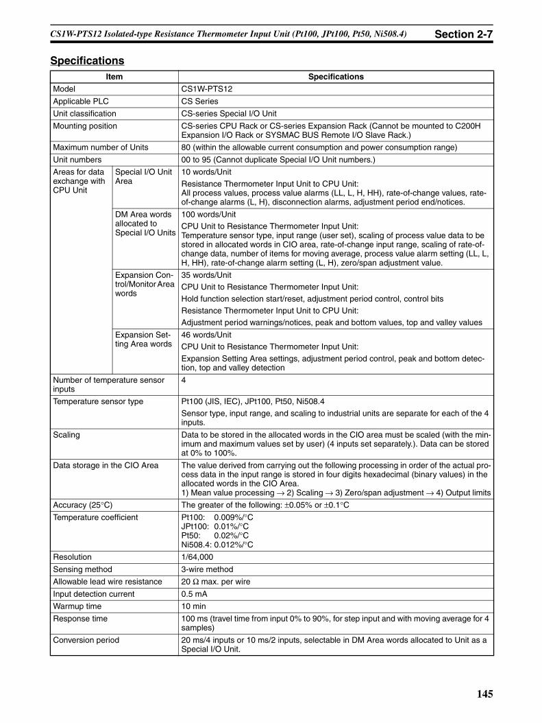
CS1W-PTS12 Isolated-type Resistance Thermometer Input Unit (Pt100, JPt100, Pt50, Ni508.4) Section 2-7
SpecificationsItem Specifications
Model CS1W-PTS12
Applicable PLC CS Series
Unit classification CS-series Special I/O Unit
Mounting position CS-series CPU Rack or CS-series Expansion Rack (Cannot be mounted to C200H Expansion I/O Rack or SYSMAC BUS Remote I/O Slave Rack.)
Maximum number of Units 80 (within the allowable current consumption and power consumption range)
Unit numbers 00 to 95 (Cannot duplicate Special I/O Unit numbers.)
Areas for data exchange with CPU Unit
Special I/O Unit Area
10 words/Unit
Resistance Thermometer Input Unit to CPU Unit:All process values, process value alarms (LL, L, H, HH), rate-of-change values, rate-of-change alarms (L, H), disconnection alarms, adjustment period end/notices.
DM Area words allocated to Special I/O Units
100 words/UnitCPU Unit to Resistance Thermometer Input Unit:Temperature sensor type, input range (user set), scaling of process value data to be stored in allocated words in CIO area, rate-of-change input range, scaling of rate-of-change data, number of items for moving average, process value alarm setting (LL, L, H, HH), rate-of-change alarm setting (L, H), zero/span adjustment value.
Expansion Con-trol/Monitor Area words
35 words/UnitCPU Unit to Resistance Thermometer Input Unit:
Hold function selection start/reset, adjustment period control, control bitsResistance Thermometer Input Unit to CPU Unit:Adjustment period warnings/notices, peak and bottom values, top and valley values
Expansion Set-ting Area words
46 words/UnitCPU Unit to Resistance Thermometer Input Unit:
Expansion Setting Area settings, adjustment period control, peak and bottom detec-tion, top and valley detection
Number of temperature sensor inputs
4
Temperature sensor type Pt100 (JIS, IEC), JPt100, Pt50, Ni508.4
Sensor type, input range, and scaling to industrial units are separate for each of the 4 inputs.
Scaling Data to be stored in the allocated words in the CIO area must be scaled (with the min-imum and maximum values set by user) (4 inputs set separately.). Data can be stored at 0% to 100%.
Data storage in the CIO Area The value derived from carrying out the following processing in order of the actual pro-cess data in the input range is stored in four digits hexadecimal (binary values) in the allocated words in the CIO Area.1) Mean value processing → 2) Scaling → 3) Zero/span adjustment → 4) Output limits
Accuracy (25°C) The greater of the following: ±0.05% or ±0.1°CTemperature coefficient Pt100: 0.009%/°C
JPt100: 0.01%/°CPt50: 0.02%/°CNi508.4: 0.012%/°C
Resolution 1/64,000
Sensing method 3-wire method
Allowable lead wire resistance 20 Ω max. per wire
Input detection current 0.5 mA
Warmup time 10 min
Response time 100 ms (travel time from input 0% to 90%, for step input and with moving average for 4 samples)
Conversion period 20 ms/4 inputs or 10 ms/2 inputs, selectable in DM Area words allocated to Unit as a Special I/O Unit.
145
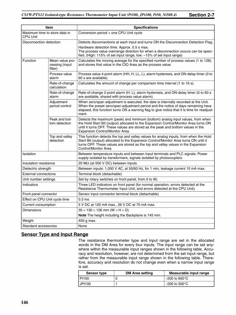
CS1W-PTS12 Isolated-type Resistance Thermometer Input Unit (Pt100, JPt100, Pt50, Ni508.4) Section 2-7
Sensor Type and Input RangeThe resistance thermometer type and input range are set in the allocatedwords in the DM Area for every four inputs. The input range can be set any-where within the measurable input ranges shown in the following table. Accu-racy and resolution, however, are not determined from the set input range, butrather from the measurable input range shown in the following table. There-fore, accuracy and resolution do not change even when a narrow input rangeis set.
Maximum time to store data in CPU Unit
Conversion period + one CPU Unit cycle
Disconnection detection Detects disconnections at each input and turns ON the Disconnection Detection Flag.Hardware detection time: Approx. 0.5 s max.The process value overrange direction for when a disconnection occurs can be speci-fied. (High: 115% of set input range; low: –15% of set input range)
Function Mean value pro-cessing (input filter)
Calculates the moving average for the specified number of process values (1 to 128), and stores that value in the CIO Area as the process value.
Process value alarm
Process value 4-point alarm (HH, H, LL, L), alarm hysteresis, and ON-delay timer (0 to 60 s are available).
Rate-of-change calculation
Calculates the amount of change per comparison time interval (1 to 16 s).
Rate-of-change alarm
Rate-of-change 2-point alarm (H, L), alarm hysteresis, and ON-delay timer (0 to 60 s are available, shared with process value alarm).
Adjustment period control
When zero/span adjustment is executed, the date is internally recorded at the Unit. When the preset zero/span adjustment period and the notice of days remaining have elapsed, this function turns ON a warning flag to give notice that it is time for readjust-ment.
Peak and bot-tom detection
Detects the maximum (peak) and minimum (bottom) analog input values, from when the Hold Start Bit (output) allocated to the Expansion Control/Monitor Area turns ON until it turns OFF. These values are stored as the peak and bottom values in the Expansion Control/Monitor Area.
Top and valley detection
This function detects the top and valley values for analog inputs, from when the Hold Start Bit (output) allocated to the Expansion Control/Monitor Area turns ON until it turns OFF. These values are stored as the top and valley values in the Expansion Control/Monitor Area.
Isolation Between temperature inputs and between input terminals and PLC signals: Power supply isolated by transformers, signals isolated by photocouplers.
Insulation resistance 20 MΩ (at 500 V DC) between inputs
Dielectric strength Between inputs: 1,000 V AC, at 50/60 Hz, for 1 min, leakage current 10 mA max.
External connections Terminal block (detachable)
Unit number settings Set by rotary switches on front panel, from 0 to 95.
Indicators Three LED indicators on front panel (for normal operation, errors detected at the Resistance Thermometer Input Unit, and errors detected at the CPU Unit).
Front panel connector Sensor input connector terminal block (detachable)
Effect on CPU Unit cycle time 0.3 ms
Current consumption 5 V DC at 120 mA max., 26 V DC at 70 mA max.
Dimensions 35 × 130 × 126 mm (W × H × D)Note The height including the Backplane is 145 mm.
Weight 450 g max.
Standard accessories None
Item Specifications
Sensor type DM Area setting Measurable input range
Pt100 0 −200 to 850°CJPt100 1 −200 to 500°C
146

CS1W-PTS12 Isolated-type Resistance Thermometer Input Unit (Pt100, JPt100, Pt50, Ni508.4) Section 2-7
DM Area AllocationsFirst word: word m. m = D20000 + unit number × 100 (unit number: 0 to 95)
Pt50 2 −200 to 649°CNi508.4 3 −50 to 150°C
Sensor type DM Area setting Measurable input range
DM Area address Data range Default Data contents
Input No. 1
Input No. 2
Input No. 3
Input No. 4
Decimal Hexadecimal
m 12345, 0 3039, 0000 hex 0000 hex Default block read commandSpecifies the direction of data transfer when the PLC is turned ON or the Unit is restarted for DM Area words m+1 to m+93.• 12345 (3039 hex): The data in words m+1
to m+93 is transferred from the Resis-tance Thermometer Input Unit to the CPUUnit. When the transfer is completed, thevalue will become 0000 hex.
• Other than 12345 (3039 hex) (such as0000 hex): The data in the allocatedwords of DM Area is transferred from theCPU Unit to the Resistance ThermometerInput Unit.
Number of inputs setting
m+1 0, 1 0000, 0001 hex 0 0: 4 inputs; 1: 2 inputs
Setting Group 1 (continuously refreshed area): Parameters that are continuously refreshed during PLC operation (regardless of the CPU Unit’s operation mode)
Process value alarm settings
m + 2 m + 10 m + 18 m + 26 –32768 to 32767
8000 to FFFF hex, 0000 to 7FFF hex
4200 (1068 hex)
Process value HH (high high limit) alarm setting(Set at process value scaling value.)
m + 3 m + 11 m + 19 m + 27 –32768 to 32767
8000 to FFFF hex, 0000 to 7FFF hex
4000 (0FA0 hex)
Process value H (high limit) alarm setting(Set at process value scaling value.)
m + 4 m + 12 m + 20 m + 28 –32768 to 32767
8000 to FFFF hex, 0000 to 7FFF hex
0 (0000 hex)
Process value L (low limit) alarm setting(Set at process value scaling value.)
m + 5 m + 13 m + 21 m + 29 –32768 to 32767
8000 to FFFF hex, 0000 to 7FFF hex
–200 (FF38 hex)
Process value LL (low low limit) alarm set-ting(Set at process value scaling value.)
Rate-of-change value alarm settings
m + 6 m + 14 m + 22 m + 30 –32768 to 32767
8000 to FFFF hex, 0000 to 7FFF hex
4000 (0FA0 hex)
Rate-of-change value H (high limit) alarm setting(Set at rate-of-change scaling value.)
m + 7 m + 15 m + 23 m + 31 –32768 to 32767
8000 to FFFF hex, 0000 to 7FFF hex
0 (0000 hex)
Rate-of-change value L (low limit) alarm set-ting(Set at rate-of-change scaling value.)
Zero/span adjustment
m + 8 m + 16 m + 24 m + 32 0 to 32000 0000 to 7D00 hex
10000 (2710 hex)
Gain for span adjustment(set value x 0.0001%)
m + 9 m + 17 m + 25 m + 33 –32000 to 32000
8300 to FFFF hex,0000 to 7D00 hex
0 (0000 hex)
Zero adjustment value(Set at process value scaling.)
Setting Group 2 (initial settings area): Parameters that are transferred one time from the CPU Unit to the Resistance Thermometer Input Unit if word m contains other than 12345 when the PLC is turned ON or the Resistance Thermometer Input Unit is restarted.
Sensor type
m+34 m+49 m+64 m+79 0 to 3 0000 to 0003 hex
0 (0000 hex) 0: Pt100; 1: JPt100: 2: Pt50: 3: Ni508.4
Process value input range settings
m+35 m+50 m+65 m+80 −32000 to 32000
8300 to FFFF hex, 0000 to 7D00 hex
4000 (0FA0 hex)
Maximum input signal value(set value x 0.1°C/°F)
m+36 m+51 m+66 m+81 −32000 to 32000
8300 to FFFF hex, 0000 to 7D00 hex
0 (0000 hex) Minimum input signal value(set value x 0.1°C/°F)
147

CS1W-PTS12 Isolated-type Resistance Thermometer Input Unit (Pt100, JPt100, Pt50, Ni508.4) Section 2-7
Note 1. The ERC indicator on the Unit’s front panel will light if an out-of-range set-ting is made in either Setting Group 1 or 2, or in the Expansion Setting Ar-ea. The offset from word m to the first word containing the out-of-rangeerror will be stored as the Address of Data Range Error in the DM Area infour digits hexadecimal. For more information, refer to 1-6 Error Process-ing.
If the first memory address where the out-of-range error occurred is in theExpansion Setting Area, the Address of Data Range Area will be +100 orlater. If the first word of the Expansion Setting Area has the error, the Ad-dress of Data Range Area will be +100.
m+37 m+52 m+67 m+82 0, 1 0000, 0001 hex 0 (0000 hex) Unit0: °C, 1: °FProcess value overrange direction at time of input disconnection
m+38 m+53 m+68 m+83 0, 1 0000, 0001 hex 0 (0000 hex) 0: High; 1: Low
Process value scaling
m+39 m+54 m+69 m+84 −32000 to 32000
8300 to FFFF hex, 0000 to 7D00 hex
4000 (0FA0 hex)
Value stored for maximum value in range (span)
m+40 m+55 m+70 m+85 −32000 to 32000
8300 to FFFF hex, 0000 to 7D00 hex
0 (0000 hex) Value stored for minimum value in range (zero)
Alarm supplementary functions
m+41 m+56 m+71 m+86 0 to 32000 0000 to 7D00 hex
40 (0028 hex) Alarm hysteresis(Set at process value scaling value. Shared with process value alarm and rate-of-change alarm.)
m+42 m+57 m+72 m+87 0 to 60 0000 to 003C hex
0 (0000 hex) Alarm ON-delay time (Unit: s)(Shared with process value alarm and rate-of-change alarm.)
Rate-of-change function
m+43 m+58 m+73 m+88 −32000 to 32000
8300 to FFFF hex, 0000 to 7D00 hex
4000 (0FA0 hex)
Rate-of-change range setting
Maximum rate-of-change value (Set value industrial unit; comparison time interval)
m+44 m+59 m+74 m+89 −32000 to 32000
8300 to FFFF hex, 0000 to 7D00 hex
−4000 (F060 hex)
Minimum rate-of-change value (Set value industrial unit; comparison time interval)
m+45 m+60 m+75 m+90 1 to 16 0001 to 0010 hex
1 (0001 hex) Rate-of-change comparison time interval(Unit: s)
m+46 m+61 m+76 m+91 −32000 to 32000
8300 to FFFF hex, 0000 to 7D00 hex
4000 (0FA0 hex)
Rate-of-change value scaling
Value stored for maxi-mum value in range
m+47 m+62 m+77 m+92 −32000 to 32000
8300 to FFFF hex, 0000 to 7D00 hex
−4000 (F060 hex)
Value stored for minimum value in range
Mean value processing function
m+48 m+63 m+78 m+93 1 to 128 0001 to 0080 hex
25 (0019 hex) Number of process values for calculating moving average for mean value processing
Display parameter
m+94 m+95 m+96 m+97 0 to 99, 100 to 1XX
0000 to 0063 hex, 0064 to 0XXX hex
0 (0000 hex) Address of Data Range Error (See note.)
Expansion Setting Area allocation settings
m+98 0 to 5 0000 to 0005 hex
--- Expansion Setting Area allocation0: Not used; 1: DM; 2: CIO; 3: W; 4: H; 5: EM
m+99 0 to 32767 0000 to 7FFF hex
--- First word for Expansion Setting Area
DM Area address Data range Default Data contents
Input No. 1
Input No. 2
Input No. 3
Input No. 4
Decimal Hexadecimal
148

CS1W-PTS12 Isolated-type Resistance Thermometer Input Unit (Pt100, JPt100, Pt50, Ni508.4) Section 2-7
2. When specifying an expansion setting area, be sure that it does not over-lap with other areas that are being used. If areas overlap, the words thatare allocated may be overwritten, resulting in unexpected operation.
3. When specifying the first word in an expansion setting area, be sure thatthe end of the memory area is not exceeded.
Expansion Setting Area AllocationsFirst word: word o. o = address specified in word m+99 in the area specifiedby word m+98 in the DM Area.
Note 1. When specifying an expansion control/monitor area be sure that it does notoverlap with other areas that are being used. If areas overlap, the wordsthat are allocated may be overwritten, resulting in unexpected operation.
2. When specifying the first word in an expansion control/monitor area besure that the end of the memory area is not exceeded.
DM Area address Data range Default Data contents
Input No. 1
Input No. 2
Input No. 3
Input No. 4
Decimal Hexadecimal
Setting Group 3 (initial settings area): Parameters that are transferred one time from the CPU Unit to the Resistance Thermometer Input Unit if word m contains other than 12345, and if Expansion Setting Area settings are allocated, when the PLC is turned ON or the Resistance Thermometer Input Unit is restarted.
Expansion Control/Monitor Area set-tings
o 0 to 5 0000 to 0005 hex
--- Expansion Control/Monitor Area allocation0: Not used. 1: DM; 2: CIO; 3: W; 4: H; 5: EM
o+1 0 to 32767 0000 to 7FFF hex
--- Expansion Control/Monitor Area first word
Zero/span adjustment supplementary function
o+2 o+13 o+24 o+35 0 to 32000 0000 to 7D00 hex
1000 (2710 hex)
Span adjustment position(Input span percentage)
o+3 o+14 o+25 o+36 −32000 to 32000
8300 to FFFF hex, 0000 to 7D00 hex
0 (0000 hex) Zero adjustment position(Input span percentage)
o+4 o+15 o+26 o+37 0 to 9999 0000 to 270F hex
365 (016D hex) Zero/span adjustment period (Unit: Days)
o+5 o+16 o+27 o+38 0 to 9999 0000 to 270F hex
30 (001E hex) Notice of days remaining (Unit: Days)
Not used.
o+6 o+17 o+28 o+39 --- --- 0 (0000 hex) Not used.
o+7 o+18 o+29 o+40
o+8 o+19 o+30 o+41
Top and valley hold
o+9 o+20 o+31 o+42 0 to 32000 0000 to 7D00 hex
40 (0028 hex) Hysteresis
Not used.
o+10 o+21 o+32 o+43 --- --- 0 (0000 hex) Not used.
o+11 o+22 o+33 o+44
o+12 o+23 o+34 o+45
149

CS1W-PTS12 Isolated-type Resistance Thermometer Input Unit (Pt100, JPt100, Pt50, Ni508.4) Section 2-7
CIO Area AllocationsFirst word: word n. n = 2000 + unit number × 10 (unit number: 0 to 95)
Direction Word Bit Name Data range Contents
Resistance Ther-mometer Input Unit to CPU Unit
n 00 Input No. 1 Process value LL (low low limit) alarm
0, 1 0: Process value > Set value1: Process value ≤ Set value
01 Process value L (low limit) alarm
0, 1
02 Process value H (high limit) alarm
0, 1 0: Process value < Set value1: Process value ≥ Set value
03 Process value HH (high high limit) alarm
0, 1
04 Input No. 2 Process value LL (low low limit) alarm
0, 1 Same as for input No. 1.
05 Process value L (low limit) alarm
0, 1
06 Process value H (high limit) alarm
0, 1
07 Process value HH (high high limit) alarm
0, 1
08 Input No. 3 Process value LL (low low limit) alarm
0, 1 Same as for input No. 1.
09 Process value L (low limit) alarm
0, 1
10 Process value H (high limit) alarm
0, 1
11 Process value HH (high high limit) alarm
0, 1
12 Input No. 4 Process value LL (low low limit) alarm
0, 1 Same as for input No. 1.
13 Process value L (low limit) alarm
0, 1
14 Process value H (high limit) alarm
0, 1
15 Process value HH (high high limit) alarm
0, 1
150

CS1W-PTS12 Isolated-type Resistance Thermometer Input Unit (Pt100, JPt100, Pt50, Ni508.4) Section 2-7
Resistance Ther-mometer Input Unit to CPU Unit
n + 1 00 to 15 Input No. 1 process value –32768 to 32767 (8000 to FFFF hex, 0000 to 7FFF hex)
The present process value is stored according to the scal-ing set in the allo-cated words of the DM Area.
n + 2 00 to 15 Input No. 2 process value –32768 to 32767 (8000 to FFFF hex, 0000 to 7FFF hex)
n + 3 00 to 15 Input No. 3 process value –32768 to 32767 (8000 to FFFF hex, 0000 to 7FFF hex)
n + 4 00 to 15 Input No. 4 process value –32768 to 32767 (8000 to FFFF hex, 0000 to 7FFF hex)
n + 5 00 to 15 Input No. 1 rate-of-change value –32768 to 32767 (8000 to FFFF hex, 0000 to 7FFF hex)
The present rate of change is stored according to the scal-ing set in the allo-cated words of the DM Area.
n + 6 00 to 15 Input No. 2 rate-of-change value –32768 to 32767 (8000 to FFFF hex, 0000 to 7FFF hex)
n + 7 00 to 15 Input No. 3 rate-of-change value –32768 to 32767 (8000 to FFFF hex, 0000 to 7FFF hex)
n + 8 00 to 15 Input No. 4 rate-of-change value –32768 to 32767 (8000 to FFFF hex, 0000 to 7FFF hex)
n + 9 00 Input No. 1 Rate-of-change value L (low limit) alarm
0, 1 0: Rate-of-change value > Set value1: Rate-of-change value ≤ Set value
01 Rate-of-change value H (high limit) alarm
0, 1 0: Rate-of-change value < Set value1: Rate-of-change value ≥ Set value
02 Input No. 2 Rate-of-change value L (low limit) alarm
0, 1 Same as for input No. 1.
03 Rate-of-change value H (high limit) alarm
0, 1
04 Input No. 3 Rate-of-change value L (low limit) alarm
0, 1 Same as for input No. 1.
05 Rate-of-change value H (high limit) alarm
0, 1
06 Input No. 4 Rate-of-change value L (low limit) alarm
0, 1 Same as for input No. 1.
07 Rate-of-change value H (high limit) alarm
0, 1
08 Input No. 1 input error 0, 1 0: Normal1: Disconnection 09 Input No. 2 input error 0, 1
10 Input No. 3 input error 0, 1 Same as for input No. 1.
11 Input No. 4 input error 0, 1 Same as for input No. 1.
12 Not used. 0 ---13 Zero/span adjustment period end 0, 1 0: Adjustment
enabled1: Adjustment ended
14 Zero/span adjustment period notice 0, 1 0: Adjustment enabled1: Notice period
15 Not used. 0 ---
Direction Word Bit Name Data range Contents
151

CS1W-PTS12 Isolated-type Resistance Thermometer Input Unit (Pt100, JPt100, Pt50, Ni508.4) Section 2-7
Expansion Control/Monitor Area AllocationsFirst word: word p. p = address specified in word o+1 in the area specified byword o in the Expansion Setting Area.
Direction Word Bit Name Data range Contents
CPU Unit to Resistance Thermome-ter Input Unit
p 00 to 15
Not used. Not used. Not used.
p+1 00 Input No. 1 hold function selec-tion
0, 1 0: Peak and bottom
1: Top and valley01 Input No. 2 hold function selec-
tion0, 1
02 Input No. 3 hold function selec-tion
0, 1
03 Input No. 4 hold function selec-tion
0, 1
04 to 07
Not used. 0 Not used.
08 Input No. 1 hold start 0, 1 0: Do not hold.
1: Hold09 Input No. 2 hold start 0, 1
10 Input No. 3 hold start 0, 1
11 Input No. 4 hold start 0, 1
12 Input No. 1 hold value reset 0, 1 0: Normal opera-tion1: Reset hold value.
13 Input No. 2 hold value reset 0, 1
14 Input No. 3 hold value reset 0, 1
15 Input No. 4 hold value reset 0, 1
p+2 00 Input No. 1 zero/span adjustment update bit
0, 1 0: Normal opera-tion1: Update adjust-ment date(Remains ON while writing external FROM.)
01 Input No. 2 zero/span adjustment update bit
0, 1
02 Input No. 3 zero/span adjustment update bit
0, 1
03 Input No. 4 zero/span adjustment update bit
0, 1
04 to 15
Not used. 0 Not used.
152

CS1W-PTS12 Isolated-type Resistance Thermometer Input Unit (Pt100, JPt100, Pt50, Ni508.4) Section 2-7
Resistance Thermome-ter Input Unit to CPU Unit
p+3 00 Input No. 1
Zero/span adjustment period end
0, 1 0: Adjustment enabled.
1: Adjustment period end
01 Zero/span adjustment period notice
0, 1 0: Adjustment enabled.1: Notice period in effect.Remains set to 1 if the zero/span adjustment bit has never been ON.
02 Input No. 2
Zero/span adjustment period end
0, 1
03 Zero/span adjustment period notice
0, 1
04 Input No. 3
Zero/span adjustment period end
0, 1
05 Zero/span adjustment period notice
0, 1
06 Input No. 4
Zero/span adjustment period end
0, 1
07 Zero/span adjustment period notice
0, 1
08 External FROM Error Flag 0, 1 0: Normal opera-tion1: External FROM error
09 to 15
Not used. 0 Not used.
p+4 00 to 15
Input No. 1
Day of final adjustment date
0100 to 3100 (BCD) Remains set to FFFF if the zero/span adjustment bit has never been ON.
p+5 00 to 15
Year and month of final adjustment date
0001 to 9912 (BCD)
p+6 00 to 15
Input No. 2
Day of final adjustment date
0100 to 3100 (BCD)
p+7 00 to 15
Year and month of final adjustment date
0001 to 9912 (BCD)
p+8 00 to 15
Input No. 3
Day of final adjustment date
0100 to 3100 (BCD)
p+9 00 to 15
Year and month of final adjustment date
0001 to 9912 (BCD)
p+10 00 to 15
Input No. 4
Day of final adjustment date
0100 to 3100 (BCD)
p+11 00 to 15
Year and month of final adjustment date
0001 to 9912 (BCD)
p+12 to p+15
00 to 15
Not used. 0 Not used.
Direction Word Bit Name Data range Contents
153

CS1W-PTS12 Isolated-type Resistance Thermometer Input Unit (Pt100, JPt100, Pt50, Ni508.4) Section 2-7
Terminal Connection Diagram
Note • Wire the same length to A, B, and b, so that the impedance will be thesame. In particular, do not short circuit between B and b at the terminalblock.
• For unused input terminals, short-circuit between A–B and B–b (e.g., A2–A3 and A3–A4 for input No. 1) of the resistance thermometer inputs withthe lead wire.
• Always ground the GR terminal on the Power Supply Unit of the PLC.
Resistance Thermome-ter Input Unit to CPU Unit
p+16 00 to 15
Input No. 1
Peak/top value −32728 to +32767(8000 to FFFF hex, 0000 to 7FFF hex)
Counts the num-ber of repetitions of conditional opera-tions set in the Expansion Setting Area.
p+17 00 to 15
Bottom/valley value −32728 to +32767
(8000 to FFFF hex, 0000 to 7FFF hex)
The bottom or val-ley value is stored according to the scaling set in the DM Area.
p+18 00 to 15
Input No. 2
Peak/top value −32728 to +32767(8000 to FFFF hex, 0000 to 7FFF hex)
Same as for Input No. 1.
p+19 00 to 15
Bottom/valley value −32728 to +32767
(8000 to FFFF hex, 0000 to 7FFF hex)
p+20 00 to 15
Input No. 3
Peak/top value −32728 to +32767
(8000 to FFFF hex, 0000 to 7FFF hex)
p+21 00 to 15
Bottom/valley value −32728 to +32767(8000 to FFFF hex, 0000 to 7FFF hex)
p+22 00 to 15
Input No. 4
Peak/top value −32728 to +32767(8000 to FFFF hex, 0000 to 7FFF hex)
p+23 00 to 15
Bottom/valley value −32728 to +32767(8000 to FFFF hex, 0000 to 7FFF hex)
p+24 to p+34
00 to 15
Not used. 0 (0000 hex) Not used.
Direction Word Bit Name Data range Contents
N.C.
N.C.
N.C.
2A
2B
2b
N.C.
N.C.
N.C.
N.C.
B1
B2
B3
B4
B5
B6
B7
B8
B9
B10
A1
A2
A3
A4
A5
A6
A7
A8
A9
A10
A11
N.C.
1A
1B
1b
3A
3B
3b
N.C.
4A
4B
4b
No. 2 Resistance thermometer input
No. 1 Resistance thermometer input
No. 3 Resistance thermometer input
No. 4 Resistance thermometer input
154

CS1W-PTS12 Isolated-type Resistance Thermometer Input Unit (Pt100, JPt100, Pt50, Ni508.4) Section 2-7
• If the input device uses a voltage generator, temperature compensator, orsimilar device, then ground the input device if it has a ground terminal.
Terminal Block Diagram
Error Processing
Conversion Data Does Not Change.
Values are Not Converted as Intended.
Probable cause Remedy
The gain for span adjustment is set to 0.
Set the gain for span adjustment to a value other than 0.
The minimum and maximum val-ues for process value scaling are either the same or are set extremely low.
Set the minimum and maximum process value scaling correctly.
The sensor type, or process value scaling is not set correctly.
Check and reset the sensor type, and the pro-cess value scaling settings.
An input device is malfunctioning, input wiring is faulty, or wiring is disconnected.
Check whether the input voltage or current has changed. Check for faulty or disconnected wir-ing. Check whether a disconnection has been detected in the I/O Area.
Probable cause Remedy
The sensor type, or process value scaling is set incorrectly.
Check and reset the sensor type, and the pro-cess value scaling settings.
The zero/span adjustment data is incorrect.
Check and correct the zero/span adjustment set-tings.
The resistance thermometer input wiring is faulty.
Check and correct the input wiring.
A2
A3
A4
B4
B5
B6
A5
A6
A7
A9
A10
A11
1A
1B
1b
A
B
2A
2B
2b
A
B
3A
3B
3b
A
B
4A
4B
4b
A
B 510 Ω
510 Ω
510 Ω
510 Ω
Reference resistance
Reference resistance
Reference resistance
Constant current circuit
Inpu
t sel
ecto
r Con
nect
or
26 VDC
5 VDC
Resistance thermometer
Resistance thermometer
Resistance thermometer
Resistance thermometer
Constant current circuit
Constant current circuit
Constant current circuit
Ampli-fier circuit
Ampli-fier circuit
Ampli-fier circuit
Ampli-fier circuit
A/D con-verter
A/D con-verter
A/D con-verter
A/D con-verter
Isolation circuit
Isolation circuit
Isolation circuit
Isolation circuit
Digital circuits
Photocoupler
Photocoupler
Photocoupler
Photocoupler
Reference resistance
155

CS1W-PTS12 Isolated-type Resistance Thermometer Input Unit (Pt100, JPt100, Pt50, Ni508.4) Section 2-7
Converted Values are Unstable.
Probable cause Remedy
Input signals are being affected by external noise.
Change the connection paths of the input signal lines. (Separate them from sources of noise or use shielded cable.)
Increase the number of values for calculating the moving average in mean value processing.
The scaling value is greater than the Unit’s resolution.
Reduce the process value scaling.
The input signal range is too small. Change to match the internal range.
156

CS1W-PTS52 Isolated-type Resistance Thermometer Input Unit (Pt100, JPt100) Section 2-8
2-8 CS1W-PTS52 Isolated-type Resistance Thermometer Input Unit (Pt100, JPt100)
OverviewThe CS1W-PTS52 Isolated-type Resistance Thermometer Input Unit providesfour direct platinum resistance thermometer inputs, and sends the data to theCPU Unit each cycle. All inputs are isolated.
CS1W-PTS52
System Configuration
Features• Up to four platinum resistance thermometers can be connected for each
Unit (with four separate settings for temperature sensors and inputranges).
• Pt100 (JIS, IEC), JPt100 can be selected.• Temperature sensor values are transmitted to the CPU Unit in four digits
hexadecimal. (Either binary or BCD data output can be selected.)• Process value alarm (two alarms in internal memory and one external
alarm output for each input).• Alarm ON-delay timer and hysteresis for process value.• Zero/span adjustment capability during operation.• Sensor error detection.• Maximum or minimum process value can be specified for when a sensor
error is detected.
Model Information
MACHNo.
X100
FEDCBA9876543210 FEDCBA9876543
210X101
RUNERC
ERH
CS1W-PTS52
Four platinum resistance thermometer inputs (Pt100 (JIS, IEC), JPt100)
Unit classification
Model number Inputs Input types
CS-series Spe-cial I/O Unit
CS1W-PTS52 4 Platinum resistance thermome-ter Pt100 (JIS, IEC), JPt100
157

CS1W-PTS52 Isolated-type Resistance Thermometer Input Unit (Pt100, JPt100) Section 2-8
Block Diagram (Order of Processing)The processing for the inputs is as shown in the following diagram.
SpecificationsItem Specifications
Model CS1W-PTS52
Applicable PLC CS Series
Unit classification CS-series Special I/O Unit
Mounting position CS-series CPU Rack or CS-series Expansion Rack (Cannot be mounted to C200H Expansion I/O Rack or SYSMAC BUS Remote I/O Slave Rack.)
Maximum number of Units 80 (within the allowable current consumption and power consumption range)
Unit numbers 00 to 95 (Cannot duplicate Special I/O Unit numbers.)
Process value alarm
Output limit
Zero/span adjustment
Input calculations
Resistance thermometer typeInput range
A/D conversion
Resistance thermometer
H, L H, L
CPU Unit
Process value Process value alarm Sensor error
CPU Unit CIO Area
Isolated-type Resistance Thermometer Input Unit I/O refresh
External alarm output
158

CS1W-PTS52 Isolated-type Resistance Thermometer Input Unit (Pt100, JPt100) Section 2-8
Areas for data exchange with CPU Unit
Special I/O Unit Area
10 words/UnitResistance Thermometer Input Unit to CPU Unit:All process values, process value alarms (L, H), conversion data enabled flag, sensor errors.
DM Area words allocated to Special I/O Units
100 words/UnitCPU Unit to Resistance Thermometer Input Unit:Temperature sensor type, input range (user set), process value alarm setting (L, H), zero/span adjustment value.
Number of temperature sensor inputs
4
Temperature sensor type Pt100 (JIS, IEC), JPt100The same sensor type, input range, and scaling to industrial units are used by all inputs.
Data storage in the CIO Area The actual process data in the input range is stored in four digits hexadecimal (binary or BCD values) in the allocated words in the CIO Area.
Accuracy (25°C) ±0.3% of PV or ±0.8°C, whichever is greater, ±1 digit max. (±0.3% of PV or ±1.6°F, whichever is greater, ±1 digit max.)
PV: Process value data
Temperature characteristics Refer to Temperature Characteristics According to Platinum Resistance Thermometer Type on page 161.
Sensing method 3-wire method
Input detection current 1 mA
Influence of conductor resistance 0.4°C/Ω max.
Conversion period 250 ms/4 inputs
Warmup time 10 min
Maximum time to store data in CPU Unit
Conversion period + one CPU Unit cycle
Sensor error detection Detects sensor error at each input and turns ON the Sensor error Flag.
Hardware detection time: Approx. 0.5 s max.The process value overrange direction for when a sensor error occurs can be speci-fied. (High: +20 digit of set input range; low: –20 digit of set input range)
Function Process value alarm
Process value 2-point alarm (H, L), alarm hysteresis, and ON-delay timer (0 to 60 s are available).
External alarm outputs
NPN outputs (with short-circuit protection)External power supply voltage: 20.4 to 26.4 V DCMax. switching capacity: 100 mA (for one output) Leakage current: 0.3 mA max.Residual voltage: 3 V max.
Isolation Between inputs and PLC signal: Transformer for power supply and photocoupler for signalsBetween each input: Transformer for power supply and photocoupler for signals
Insulation resistance 20 MΩ max. (at 500 V DC).Between all output and NC terminals and external AC terminals (Power Supply Unit)Between all input terminals and external AC terminals (Power Supply Unit)
Between all input terminals and all output terminalsBetween all external DC terminals (input, output, and NC terminals) and FG plateBetween all input and output terminals and all NC terminals
Item Specifications
159
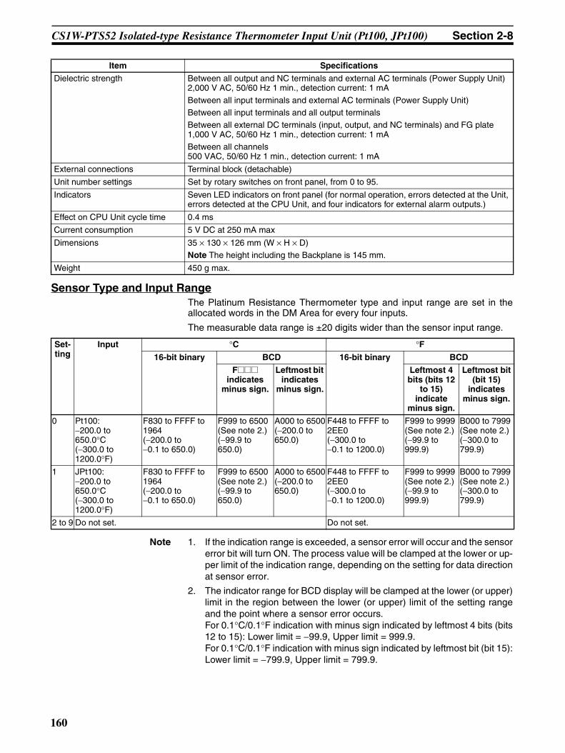
CS1W-PTS52 Isolated-type Resistance Thermometer Input Unit (Pt100, JPt100) Section 2-8
Sensor Type and Input RangeThe Platinum Resistance Thermometer type and input range are set in theallocated words in the DM Area for every four inputs.
The measurable data range is ±20 digits wider than the sensor input range.
Note 1. If the indication range is exceeded, a sensor error will occur and the sensorerror bit will turn ON. The process value will be clamped at the lower or up-per limit of the indication range, depending on the setting for data directionat sensor error.
2. The indicator range for BCD display will be clamped at the lower (or upper)limit in the region between the lower (or upper) limit of the setting rangeand the point where a sensor error occurs.For 0.1°C/0.1°F indication with minus sign indicated by leftmost 4 bits (bits12 to 15): Lower limit = −99.9, Upper limit = 999.9.For 0.1°C/0.1°F indication with minus sign indicated by leftmost bit (bit 15):Lower limit = −799.9, Upper limit = 799.9.
Dielectric strength Between all output and NC terminals and external AC terminals (Power Supply Unit)2,000 V AC, 50/60 Hz 1 min., detection current: 1 mA
Between all input terminals and external AC terminals (Power Supply Unit)Between all input terminals and all output terminalsBetween all external DC terminals (input, output, and NC terminals) and FG plate1,000 V AC, 50/60 Hz 1 min., detection current: 1 mABetween all channels500 VAC, 50/60 Hz 1 min., detection current: 1 mA
External connections Terminal block (detachable)
Unit number settings Set by rotary switches on front panel, from 0 to 95.
Indicators Seven LED indicators on front panel (for normal operation, errors detected at the Unit, errors detected at the CPU Unit, and four indicators for external alarm outputs.)
Effect on CPU Unit cycle time 0.4 ms
Current consumption 5 V DC at 250 mA max
Dimensions 35 × 130 × 126 mm (W × H × D)Note The height including the Backplane is 145 mm.
Weight 450 g max.
Item Specifications
Set-ting
Input °C °F16-bit binary BCD 16-bit binary BCD
F@@@ indicates
minus sign.
Leftmost bit indicates
minus sign.
Leftmost 4 bits (bits 12
to 15) indicate
minus sign.
Leftmost bit (bit 15)
indicates minus sign.
0 Pt100:−200.0 to 650.0°C(−300.0 to 1200.0°F)
F830 to FFFF to 1964(−200.0 to −0.1 to 650.0)
F999 to 6500 (See note 2.)(−99.9 to 650.0)
A000 to 6500(−200.0 to 650.0)
F448 to FFFF to 2EE0(−300.0 to −0.1 to 1200.0)
F999 to 9999 (See note 2.)(−99.9 to 999.9)
B000 to 7999 (See note 2.)(−300.0 to 799.9)
1 JPt100:−200.0 to 650.0°C(−300.0 to 1200.0°F)
F830 to FFFF to 1964(−200.0 to −0.1 to 650.0)
F999 to 6500 (See note 2.)(−99.9 to 650.0)
A000 to 6500(−200.0 to 650.0)
F448 to FFFF to 2EE0(−300.0 to −0.1 to 1200.0)
F999 to 9999 (See note 2.)(−99.9 to 999.9)
B000 to 7999 (See note 2.)(−300.0 to 799.9)
2 to 9 Do not set. Do not set.
160

CS1W-PTS52 Isolated-type Resistance Thermometer Input Unit (Pt100, JPt100) Section 2-8
Temperature Characteristics According to Platinum Resistance Thermometer Type
The measured temperature error is calculated as shown in the followingexample.
Overall accuracy = Reference accuracy + Temperature characteristic × Change in ambienttemperature = ±1.5°C + ±0.143°C × 5 = Approx. ± 2.2°C ±1 digit.
DM Area AllocationsFirst word: word m. m = D20000 + unit number × 100 (unit number: 0 to 95)
Platinum Resistance Thermometer
Temperature range Set value error when ambient temperature
changes by 1°CPt100 −200 to 200°C ±0.06°C
200 to 650°C 285 ppm of PV
JPt100 −200 to 200°C ±0.06°C200 to 650°C 285 ppm of PV
Item Details
Ambient temperature 30°CPlatinum Resistance Thermometer
Pt100
Measured temperature (PV)
500°C
Reference accuracy (25°C)
±0.3°C of PV or ±0.8°C, whichever is greater, ±1 digit.In this example, ±1.5°C.
Temperature characteris-tics
200 to 650°C: 285 ppm of PV.In this example, 285 ppm × 500°C = 0.143°C.
Change in ambient tem-perature
5°C (25 to 30°C)
DM Area address Data range Default Data contents
Input No. 1
Input No. 2
Input No. 3
Input No. 4
Decimal Hexadecimal
m 12345, 0 3039, 0000 hex 0000 hex Default block read commandSpecifies the direction of data transfer when the PLC is turned ON or the Unit is restarted for DM Area words m+1 to m+93.• 12345 (3039 hex): The data in words m+1
to m+93 is transferred from the Resis-tance Thermometer Input Unit to the CPUUnit. When the transfer is completed, thevalue will become 0000 hex.
• Other than 12345 (3039 hex) (such as0000 hex): The data in the allocatedwords of DM Area is transferred from theCPU Unit to the Resistance ThermometerInput Unit.
Display parameter
m + 1 0 to 34 0000 to 0022 hex
0 (0000 hex)
Address of Data Range Error (See note 1.)
Setting Group 1 (continuously refreshed area): Parameters that are continuously refreshed during PLC operation (regardless of the CPU Unit’s operation mode)
Process value alarm settings
m + 2 m + 6 m + 10 m + 14 Low to high limit for all sensors 6500 (1964 hex)
Process value H (high limit) alarm setting
m + 3 m + 7 m + 11 m + 15 −2000 (F830 hex)
Process value L (low limit) alarm setting
Span adjustment value
161

CS1W-PTS52 Isolated-type Resistance Thermometer Input Unit (Pt100, JPt100) Section 2-8
Note 1. The ERC indicator on the Unit’s front panel will light if an out-of-range set-ting is made in either Setting Group 1 or 2. The offset from word m to thefirst word containing the out-of-range error will be stored as the Address ofData Range Error in the DM Area in four digits hexadecimal.
2. The operation settings are shown in the following table.
Example: For a temperature in degrees Celsius (°C), a binary data format, and a datadirection at sensor error of “lower limit,” word m+18 contains 1000.
3. Indicates the value after transferring the default value (set when 12345 iswritten to word m).
m + 4 m + 8 m + 12 m + 16 0 to 9999 0000 to 270F hex
1000 (03E8 hex)
m+35 contains 0: Set value × 0.001
0 to 32000 0000 to 7D00 hex
10000 (2710 hex)
m+35 contains 1: Set value × 0.0001
Zero adjustment value
m + 5 m + 9 m + 13 m + 17 –9999 to 9999 D8F1 to 270F hex
0 (0000 hex)
Set value × 0.1
Setting Group 2 (initial settings area): Parameters that are transferred one time from the CPU Unit to the Resistance Thermometer Input Unit if word m contains other than 12345 when the PLC is turned ON or the Resistance Thermometer Input Unit is restarted.
Operation settings (See note 2.)
m + 18 (See note 2.) (See note 2.) 0(0000 hex)
00 to 03: Temperature unit (°C or °F)04 to 07: Data display (binary or BCD)08 to 11: Minus sign display format for BCD display12 to 15: Data direction at sensor error
Sensor type
m + 19 m + 23 m + 27 m + 31 0 to 1 0000, 0001 hex 0 (0000 hex) 0: Pt100; 1: JPt100
External alarm output mode
m + 20 m + 24 m + 28 m + 32 0, 1 0000, 0001 hex 0 (0000 hex)
Select either high limit or low limit alarm out-put.0: High limit alarm; 1: Low limit alarm
Alarm hysteresis
m + 21 m + 25 m + 29 m + 33 0 to 9999 0000 to 270F hex
0 (0000 hex)
Set value × 0.1
Alarm ON-delay time
m + 22 m + 26 m + 30 m + 34 0 to 60 0000 to 003C hex
0 (0000 hex)
Unit: s
m + 35 0, 1 0000, 0001 hex 1 (See note 3.) Span adjustment mode0: 1/1,0001: 1/10,000
DM Area address Data range Default Data contents
Input No. 1
Input No. 2
Input No. 3
Input No. 4
Decimal Hexadecimal
Word Bits Description Settings
m+18 00 Temperature unit setting 0: °C1: °F
04 Data format 0: Binary (Negative values are given as 2’s comple-ments).1: BCD
08 Minus sign display format for BCD display 0: “F” used to indicate the minus sign.1: Leftmost bit used to indicate the minus sign.
The setting is disabled if bits 04 to 07 are set to 0.
12 Data direction at sensor error 0: Goes to upper limit at sensor error1: Goes to lower limit at sensor error
162
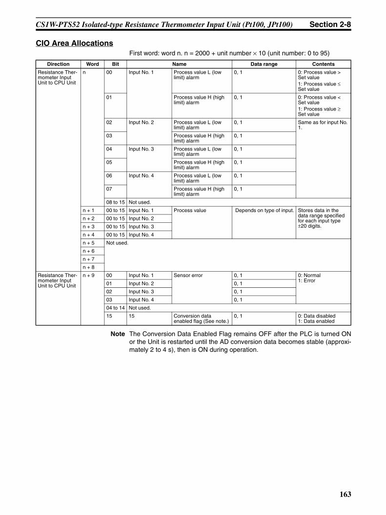
CS1W-PTS52 Isolated-type Resistance Thermometer Input Unit (Pt100, JPt100) Section 2-8
CIO Area AllocationsFirst word: word n. n = 2000 + unit number × 10 (unit number: 0 to 95)
Note The Conversion Data Enabled Flag remains OFF after the PLC is turned ONor the Unit is restarted until the AD conversion data becomes stable (approxi-mately 2 to 4 s), then is ON during operation.
Direction Word Bit Name Data range Contents
Resistance Ther-mometer Input Unit to CPU Unit
n 00 Input No. 1 Process value L (low limit) alarm
0, 1 0: Process value > Set value1: Process value ≤ Set value
01 Process value H (high limit) alarm
0, 1 0: Process value < Set value1: Process value ≥ Set value
02 Input No. 2 Process value L (low limit) alarm
0, 1 Same as for input No. 1.
03 Process value H (high limit) alarm
0, 1
04 Input No. 3 Process value L (low limit) alarm
0, 1
05 Process value H (high limit) alarm
0, 1
06 Input No. 4 Process value L (low limit) alarm
0, 1
07 Process value H (high limit) alarm
0, 1
08 to 15 Not used.
n + 1 00 to 15 Input No. 1 Process value Depends on type of input. Stores data in the data range specified for each input type ±20 digits.
n + 2 00 to 15 Input No. 2
n + 3 00 to 15 Input No. 3
n + 4 00 to 15 Input No. 4
n + 5 Not used.
n + 6
n + 7
n + 8
Resistance Ther-mometer Input Unit to CPU Unit
n + 9 00 Input No. 1 Sensor error 0, 1 0: Normal1: Error01 Input No. 2 0, 1
02 Input No. 3 0, 1
03 Input No. 4 0, 1
04 to 14 Not used.
15 15 Conversion data enabled flag (See note.)
0, 1 0: Data disabled1: Data enabled
163
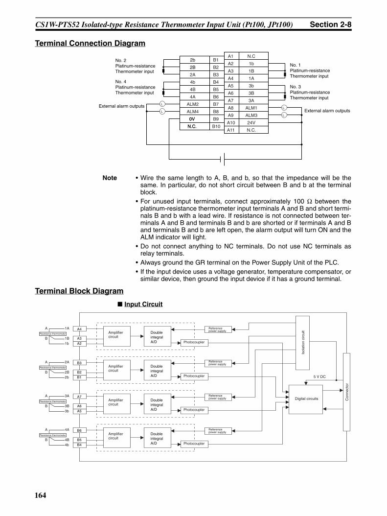
CS1W-PTS52 Isolated-type Resistance Thermometer Input Unit (Pt100, JPt100) Section 2-8
Terminal Connection Diagram
Note • Wire the same length to A, B, and b, so that the impedance will be thesame. In particular, do not short circuit between B and b at the terminalblock.
• For unused input terminals, connect approximately 100 Ω between theplatinum-resistance thermometer input terminals A and B and short termi-nals B and b with a lead wire. If resistance is not connected between ter-minals A and B and terminals B and b are shorted or if terminals A and Band terminals B and b are left open, the alarm output will turn ON and theALM indicator will light.
• Do not connect anything to NC terminals. Do not use NC terminals asrelay terminals.
• Always ground the GR terminal on the Power Supply Unit of the PLC.• If the input device uses a voltage generator, temperature compensator, or
similar device, then ground the input device if it has a ground terminal.
Terminal Block Diagram
Input Circuit
External alarm outputs
2b
2B
2A
4b
4B
4A
ALM2
ALM4
0V 0V
N.C. N.C.
B1
B2
B3
B4
B5
B6
B7
B8
B9
B10
A1
A2
A3
A4
A5
A6
A7
A8
A9
A10
A11
N.C
1b
1B
1A
3b
3B
3A
ALM1
ALM3
24V
N.C.
External alarm outputsL
L
L
L
No. 2 Platinum-resistance Thermometer input
No. 4 Platinum-resistance Thermometer input
No. 1 Platinum-resistance Thermometer input
No. 3 Platinum-resistance Thermometer input
5 V DC
Con
nect
or
Amplifier circuit
Photocoupler
A4
A2
Amplifier circuit
Photocoupler
Amplifier circuit
Photocoupler
Amplifier circuit
Photocoupler
Isol
atio
n ci
rcui
t
Digital circuits
A3
1A
1B1b
A
BResistance thermometer
B3
B1B2
2A
2B2b
A
BResistance thermometer
A7
A5A6
3A
3B3b
A
BResistance thermometer
B6
B4B5
4A
4B4b
A
BResistance thermometer
Double integral A/D
Reference power supply
Double integral A/D
Double integral A/D
Double integral A/D
Reference power supply
Reference power supply
Reference power supply
164
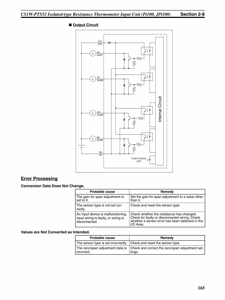
CS1W-PTS52 Isolated-type Resistance Thermometer Input Unit (Pt100, JPt100) Section 2-8
Output Circuit
Error Processing
Conversion Data Does Not Change.
Values are Not Converted as Intended.
Inte
rnal
Circ
uit
L
L
L
L
Output DisplayLED
B7ALM2
A9ALM3
B8ALM4
B90V
A1024V
A8ALM1
Probable cause Remedy
The gain for span adjustment is set to 0.
Set the gain for span adjustment to a value other than 0.
The sensor type is not set cor-rectly.
Check and reset the sensor type.
An input device is malfunctioning, input wiring is faulty, or wiring is disconnected.
Check whether the resistance has changed. Check for faulty or disconnected wiring. Check whether a sensor error has been detected in the I/O Area.
Probable cause Remedy
The sensor type is set incorrectly. Check and reset the sensor type.
The zero/span adjustment data is incorrect.
Check and correct the zero/span adjustment set-tings.
165

CS1W-PTS52 Isolated-type Resistance Thermometer Input Unit (Pt100, JPt100) Section 2-8
Converted Values are Unstable.
The platinum-resistance thermom-eter input wiring is faulty.
Check and correct the input wiring.
The compensating conductor is too long and measurements are being affected by conductor resis-tance.
Use a thicker compensating conductor.
Probable cause Remedy
Input signals are being affected by external noise.
Change the connection paths of the input signal lines. (Separate them from sources of noise or use shielded cable.)
Probable cause Remedy
166

CS1W-PTS56 Isolated-type Resistance Thermometer Input Unit (Pt100, JPt100) Section 2-9
2-9 CS1W-PTS56 Isolated-type Resistance Thermometer Input Unit (Pt100, JPt100)
OverviewThe CS1W-PTS56 Isolated-type Resistance Thermometer Input Unit provides8 direct platinum resistance thermometer inputs, and sends the data to theCPU Unit each cycle. All inputs are isolated.
CS1W-PTS56
System Configuration
Features• Up to 8 platinum resistance thermometers can be connected for each Unit
(with 8 separate settings for temperature sensors and input ranges).• Pt100 (JIS, IEC), JPt100 can be selected.• Temperature sensor values are transmitted to the CPU Unit in four digits
hexadecimal. (Either binary or BCD data output can be selected.)• Process value alarms (Two internal alarms per input can be output to
memory and two alarms per input can be output to specified I/O memoryarea addresses using indirect address specifications).
• Alarm ON-delay timer and hysteresis for process value.• Zero/span adjustment capability during operation.• Sensor error detection.• Maximum or minimum process value can be specified for when a sensor
error is detected.
Model Information
MACHNo.
X100
FEDCBA9876543210 FEDCBA9876543
210X101
RUNERC
ERH
CS1W-PTS56
8 platinum resistance thermometer inputs (Pt100 (JIS, IEC), JPt100)
Unit classification
Model number Inputs Input types
CS-series Spe-cial I/O Unit
CS1W-PTS56 8 Platinum resistance thermome-ter Pt100 (JIS, IEC), JPt100
167

CS1W-PTS56 Isolated-type Resistance Thermometer Input Unit (Pt100, JPt100) Section 2-9
Block Diagram (Order of Processing)The processing for the inputs is as shown in the following diagram.
SpecificationsItem Specifications
Model CS1W-PTS56
Applicable PLC CS Series
Unit classification CS-series Special I/O Unit
Mounting position CS-series CPU Rack or CS-series Expansion Rack (Cannot be mounted to C200H Expansion I/O Rack or SYSMAC BUS Remote I/O Slave Rack.)
Maximum number of Units 80 (within the allowable current consumption and power consumption range)
Unit numbers 00 to 95 (Cannot duplicate Special I/O Unit numbers.)
Areas for data exchange with CPU Unit
Special I/O Unit Area
10 words/UnitResistance Thermometer Input Unit to CPU Unit:All process values, process value alarms (L, H), conversion data enabled flag, sensor errors.
DM Area words allocated to Special I/O Units
100 words/UnitCPU Unit to Resistance Thermometer Input Unit:Temperature sensor type, input range (user set), process value alarm setting (L, H), zero/span adjustment value.
Expansion Set-ting Area
1 word/UnitCPU Unit to Resistance Thermometer Input Unit:Process Value Alarm
H, L
Alarm output
Process value alarm
H, L
CPU Unit
Process value Process value alarm Sensor error
CPU Unit CIO Area
Isolated-type Resistance Thermometer Input Unit I/O refresh
Expansion Setting Area
When input disconnection is detected
Zero/span adjustment
Input calculationsResistance thermometer typeInput range
A/D conversion
Resistance thermometer
Sensor error check
168
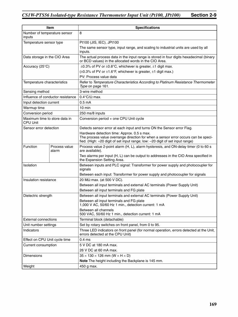
CS1W-PTS56 Isolated-type Resistance Thermometer Input Unit (Pt100, JPt100) Section 2-9
Number of temperature sensor inputs
8
Temperature sensor type Pt100 (JIS, IEC), JPt100The same sensor type, input range, and scaling to industrial units are used by all inputs.
Data storage in the CIO Area The actual process data in the input range is stored in four digits hexadecimal (binary or BCD values) in the allocated words in the CIO Area.
Accuracy (25°C) ±0.3% of PV or ±0.8°C, whichever is greater, ±1 digit max. (±0.3% of PV or ±1.6°F, whichever is greater, ±1 digit max.)
PV: Process value data
Temperature characteristics Refer to Temperature Characteristics According to Platinum Resistance Thermometer Type on page 161.
Sensing method 3-wire method
Influence of conductor resistance 0.4°C/Ω max.
Input detection current 0.5 mA
Warmup time 10 min
Conversion period 250 ms/8 inputs
Maximum time to store data in CPU Unit
Conversion period + one CPU Unit cycle
Sensor error detection Detects sensor error at each input and turns ON the Sensor error Flag.
Hardware detection time: Approx. 0.5 s max.The process value overrange direction for when a sensor error occurs can be speci-fied. (High: +20 digit of set input range; low: –20 digit of set input range)
Function Process value alarm
Process value 2-point alarm (H, L), alarm hysteresis, and ON-delay timer (0 to 60 s are available).Two alarms per input (H, L) can be output to addresses in the CIO Area specified in the Expansion Setting Area.
Isolation Between inputs and PLC signal: Transformer for power supply and photocoupler for signalsBetween each input: Transformer for power supply and photocoupler for signals
Insulation resistance 20 MΩ max. (at 500 V DC).Between all input terminals and external AC terminals (Power Supply Unit)Between all input terminals and FG plate
Dielectric strength Between all input terminals and external AC terminals (Power Supply Unit)Between all input terminals and FG plate1,000 V AC, 50/60 Hz 1 min., detection current: 1 mA
Between all channels500 VAC, 50/60 Hz 1 min., detection current: 1 mA
External connections Terminal block (detachable)
Unit number settings Set by rotary switches on front panel, from 0 to 95.
Indicators Three LED indicators on front panel (for normal operation, errors detected at the Unit, errors detected at the CPU Unit)
Effect on CPU Unit cycle time 0.4 ms
Current consumption 5 V DC at 180 mA max.26 V DC at 60 mA max.
Dimensions 35 × 130 × 126 mm (W × H × D)Note The height including the Backplane is 145 mm.
Weight 450 g max.
Item Specifications
169
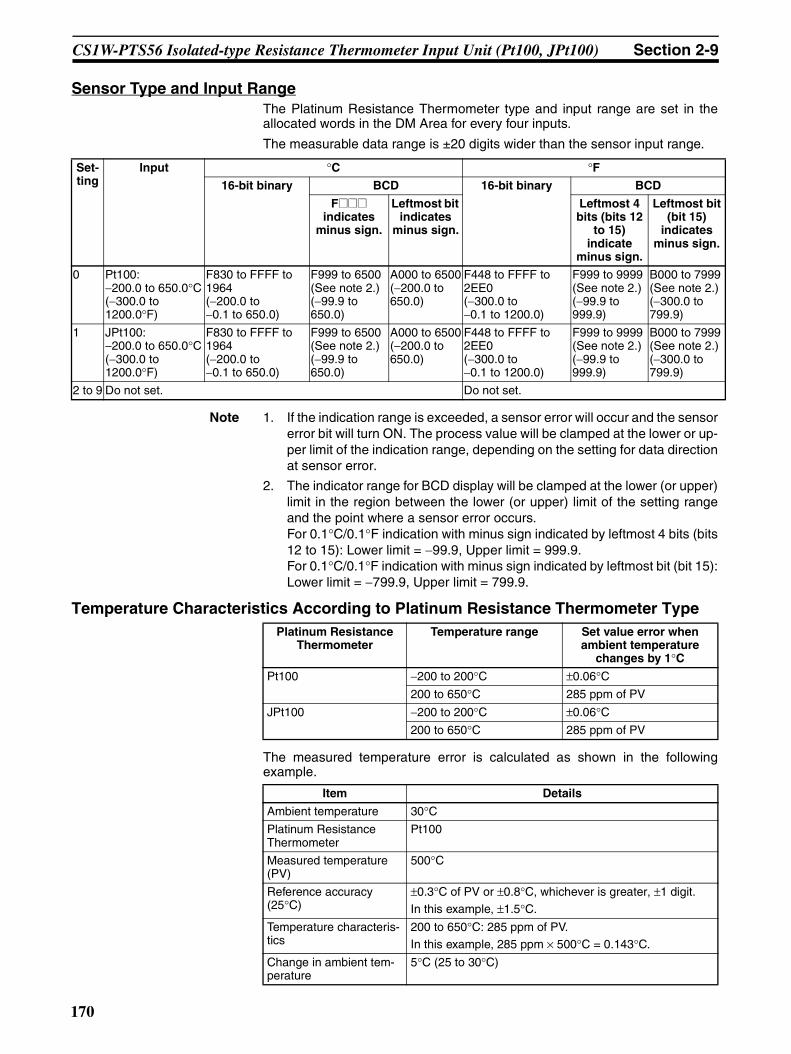
CS1W-PTS56 Isolated-type Resistance Thermometer Input Unit (Pt100, JPt100) Section 2-9
Sensor Type and Input RangeThe Platinum Resistance Thermometer type and input range are set in theallocated words in the DM Area for every four inputs.
The measurable data range is ±20 digits wider than the sensor input range.
Note 1. If the indication range is exceeded, a sensor error will occur and the sensorerror bit will turn ON. The process value will be clamped at the lower or up-per limit of the indication range, depending on the setting for data directionat sensor error.
2. The indicator range for BCD display will be clamped at the lower (or upper)limit in the region between the lower (or upper) limit of the setting rangeand the point where a sensor error occurs.For 0.1°C/0.1°F indication with minus sign indicated by leftmost 4 bits (bits12 to 15): Lower limit = −99.9, Upper limit = 999.9.For 0.1°C/0.1°F indication with minus sign indicated by leftmost bit (bit 15):Lower limit = −799.9, Upper limit = 799.9.
Temperature Characteristics According to Platinum Resistance Thermometer Type
The measured temperature error is calculated as shown in the followingexample.
Set-ting
Input °C °F16-bit binary BCD 16-bit binary BCD
F@@@ indicates
minus sign.
Leftmost bit indicates
minus sign.
Leftmost 4 bits (bits 12
to 15) indicate
minus sign.
Leftmost bit (bit 15)
indicates minus sign.
0 Pt100:−200.0 to 650.0°C(−300.0 to 1200.0°F)
F830 to FFFF to 1964(−200.0 to −0.1 to 650.0)
F999 to 6500 (See note 2.)(−99.9 to 650.0)
A000 to 6500(−200.0 to 650.0)
F448 to FFFF to 2EE0(−300.0 to −0.1 to 1200.0)
F999 to 9999 (See note 2.)(−99.9 to 999.9)
B000 to 7999 (See note 2.)(−300.0 to 799.9)
1 JPt100:−200.0 to 650.0°C(−300.0 to 1200.0°F)
F830 to FFFF to 1964(−200.0 to −0.1 to 650.0)
F999 to 6500 (See note 2.)(−99.9 to 650.0)
A000 to 6500(−200.0 to 650.0)
F448 to FFFF to 2EE0(−300.0 to −0.1 to 1200.0)
F999 to 9999 (See note 2.)(−99.9 to 999.9)
B000 to 7999 (See note 2.)(−300.0 to 799.9)
2 to 9 Do not set. Do not set.
Platinum Resistance Thermometer
Temperature range Set value error when ambient temperature
changes by 1°CPt100 −200 to 200°C ±0.06°C
200 to 650°C 285 ppm of PV
JPt100 −200 to 200°C ±0.06°C200 to 650°C 285 ppm of PV
Item Details
Ambient temperature 30°CPlatinum Resistance Thermometer
Pt100
Measured temperature (PV)
500°C
Reference accuracy (25°C)
±0.3°C of PV or ±0.8°C, whichever is greater, ±1 digit.In this example, ±1.5°C.
Temperature characteris-tics
200 to 650°C: 285 ppm of PV.In this example, 285 ppm × 500°C = 0.143°C.
Change in ambient tem-perature
5°C (25 to 30°C)
170
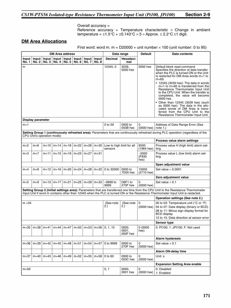
CS1W-PTS56 Isolated-type Resistance Thermometer Input Unit (Pt100, JPt100) Section 2-9
Overall accuracy = Reference accuracy + Temperature characteristic × Change in ambienttemperature = ±1.5°C + ±0.143°C × 5 = Approx. ± 2.2°C ±1 digit.
DM Area AllocationsFirst word: word m. m = D20000 + unit number × 100 (unit number: 0 to 95)
DM Area address Data range Default Data contents
Input No. 1
Input No. 2
Input No. 3
Input No. 4
Input No. 5
Input No. 6
Input No. 7
Input No. 8
Decimal Hexadeci-mal
m 12345, 0 3039, 0000 hex
0000 hex Default block read commandSpecifies the direction of data transfer when the PLC is turned ON or the Unit is restarted for DM Area words m+1 to m+60.• 12345 (3039 hex): The data in words
m+1 to m+60 is transferred from theResistance Thermometer Input Unitto the CPU Unit. When the transfer iscompleted, the value will become0000 hex.
• Other than 12345 (3039 hex) (suchas 0000 hex): The data in the allo-cated words of DM Area is trans-ferred from the CPU Unit to theResistance Thermometer Input Unit.
Display parameter
m+1 0 to 59 0000 to 003B hex
0 (0000 hex)
Address of Data Range Error (See note 1.)
Setting Group 1 (continuously refreshed area): Parameters that are continuously refreshed during PLC operation (regardless of the CPU Unit’s operation mode)
Process value alarm settings
m+2 m+6 m+10 m+14 m+18 m+22 m+26 m+30 Low to high limit for all sensors
6500 (1964 hex)
Process value H (high limit) alarm set-ting
m+3 m+7 m+11 m+15 m+19 m+23 m+27 m+31 −2000 (F830 hex)
Process value L (low limit) alarm set-ting
Span adjustment value
m+4 m+8 m+12 m+16 m+20 m+24 m+28 m+32 0 to 32000 0000 to 7D00 hex
10000 (2710 hex)
Set value × 0.0001
Zero adjustment value
m+5 m+9 m+13 m+17 m+21 m+25 m+29 m+33 –9999 to 9999
D8F1 to 270F hex
0 (0000 hex)
Set value × 0.1
Setting Group 2 (initial settings area): Parameters that are transferred one time from the CPU Unit to the Resistance Thermometer Input Unit if word m contains other than 12345 when the PLC is turned ON or the Resistance Thermometer Input Unit is restarted.
Operation settings (See note 2.)
m +34 (See note 2.)
(See note 2.)
0(0000 hex)
00 to 03: Temperature unit (°C or °F)04 to 07: Data display (binary or BCD)08 to 11: Minus sign display format for BCD display12 to 15: Data direction at sensor error
Sensor type
m+35 m+38 m+41 m+44 m+47 m+50 m+53 m+56 0, 1, 15 0000, 0001, 000F hex
0 (0000 hex)
0: Pt100; 1: JPt100, F: Not used
Alarm hysteresis
m+36 m+39 m+42 m+45 m+48 m+51 m+54 m+57 0 to 9999 0000 to 270F hex
0 (0000 hex)
Set value × 0.1
Alarm ON-delay time
m+37 m+40 m+43 m+46 m+49 m+52 m+55 m+58 0 to 60 0000 to 003C hex
0 (0000 hex)
Unit: s
Expansion Setting Area enable
m+59 0, 1 0000, 0001 hex
0 (0000 hex)
0: Disabled1: Enabled
171

CS1W-PTS56 Isolated-type Resistance Thermometer Input Unit (Pt100, JPt100) Section 2-9
Note 1. The ERC indicator on the Unit’s front panel will light if an out-of-range set-ting is made in either Setting Group 1 or 2. The offset from word m to thefirst word containing the out-of-range error will be stored as the Address ofData Range Error in the DM Area in four digits hexadecimal.
2. The operation settings are shown in the following table.
3. A range check is not performed for the Expansion Setting Area address setin word m+60. Be sure to check this address before starting actual opera-tion.
Example: For a temperature in degrees Celsius (°C), a binary data format,and a data direction at sensor error of “lower limit,” word m+18 contains 1000.
Expansion Setting Area address
m+60(See note 3)
0 to 6143 0000 to 17FF hex
0 (0000 hex)
CIO area (fixed)Number of words.
DM Area address Data range Default Data contents
Input No. 1
Input No. 2
Input No. 3
Input No. 4
Input No. 5
Input No. 6
Input No. 7
Input No. 8
Decimal Hexadeci-mal
Word Bits Description Settings
m+34 00 Temperature unit setting 0: °C1: °F
04 Data format 0: Binary (Negative values are given as 2’s comple-ments).
1: BCD
08 Minus sign display format for BCD display 0: “F” used to indicate the minus sign.1: Leftmost bit used to indicate the minus sign.
The setting is disabled if bits 04 to 07 are set to 0.
12 Data direction at sensor error 0: Goes to upper limit at sensor error
1: Goes to lower limit at sensor error
172
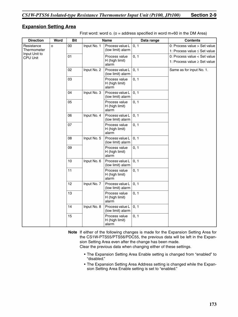
CS1W-PTS56 Isolated-type Resistance Thermometer Input Unit (Pt100, JPt100) Section 2-9
Expansion Setting AreaFirst word: word o. (o = address specified in word m+60 in the DM Area)
Note If either of the following changes is made for the Expansion Setting Area forthe CS1W-PTS55/PTS56/PDC55, the previous data will be left in the Expan-sion Setting Area even after the change has been made.Clear the previous data when changing either of these settings.
• The Expansion Setting Area Enable setting is changed from “enabled” to“disabled.”
• The Expansion Setting Area Address setting is changed while the Expan-sion Setting Area Enable setting is set to “enabled.”
Direction Word Bit Name Data range Contents
Resistance Thermometer Input Unit to CPU Unit
o 00 Input No. 1 Process value L (low limit) alarm
0, 1 0: Process value > Set value1: Process value ≤ Set value
01 Process value H (high limit) alarm
0, 1 0: Process value < Set value1: Process value ≥ Set value
02 Input No. 2 Process value L (low limit) alarm
0, 1 Same as for input No. 1.
03 Process value H (high limit) alarm
0, 1
04 Input No. 3 Process value L (low limit) alarm
0, 1
05 Process value H (high limit) alarm
0, 1
06 Input No. 4 Process value L (low limit) alarm
0, 1
07 Process value H (high limit) alarm
0, 1
08 Input No. 5 Process value L (low limit) alarm
0, 1
09 Process value H (high limit) alarm
0, 1
10 Input No. 6 Process value L (low limit) alarm
0, 1
11 Process value H (high limit) alarm
0, 1
12 Input No. 7 Process value L (low limit) alarm
0, 1
13 Process value H (high limit) alarm
0, 1
14 Input No. 8 Process value L (low limit) alarm
0, 1
15 Process value H (high limit) alarm
0, 1
173

CS1W-PTS56 Isolated-type Resistance Thermometer Input Unit (Pt100, JPt100) Section 2-9
CIO Area AllocationsFirst word: word n. n = 2000 + unit number × 10 (unit number: 0 to 95)
Note The Conversion Data Enabled Flag remains OFF after the PLC is turned ONor the Unit is restarted until the AD conversion data becomes stable (approxi-mately 2 to 4 s), then is ON during operation.
Direction Word Bit Name Data range Contents
Resistance Ther-mometer Input Unit to CPU Unit
n 00 Input No. 1 Process value L (low limit) alarm
0, 1 0: Process value > Set value1: Process value ≤ Set value
01 Process value H (high limit) alarm
0, 1 0: Process value < Set value1: Process value ≥ Set value
02 Input No. 2 Process value L (low limit) alarm
0, 1 Same as for input No. 1.
03 Process value H (high limit) alarm
0, 1
04 Input No. 3 Process value L (low limit) alarm
0, 1
05 Process value H (high limit) alarm
0, 1
06 Input No. 4 Process value L (low limit) alarm
0, 1
07 Process value H (high limit) alarm
0, 1
08 Input No. 5 Process value L (low limit) alarm
0, 1
09 Process value H (high limit) alarm
0, 1
10 Input No. 6 Process value L (low limit) alarm
0, 1
11 Process value H (high limit) alarm
0, 1
12 Input No. 7 Process value L (low limit) alarm
0, 1
13 Process value H (high limit) alarm
0, 1
14 Input No. 8 Process value L (low limit) alarm
0, 1
15 Process value H (high limit) alarm
0, 1
n + 1 00 to 15 Input No. 1 Process value Depends on type of input. Stores data in the data range specified for each input type ±20 digits.
n + 2 00 to 15 Input No. 2
n + 3 00 to 15 Input No. 3
n + 4 00 to 15 Input No. 4
n + 5 00 to 15 Input No. 5
n + 6 00 to 15 Input No. 6
n + 7 00 to 15 Input No. 7
n + 8 00 to 15 Input No. 8
Resistance Ther-mometer Input Unit to CPU Unit
n + 9 00 Input No. 1 Sensor error 0, 1 0: Normal1: Error01 Input No. 2 0, 1
02 Input No. 3 0, 1
03 Input No. 4 0, 1
04 Input No. 5 0, 1
05 Input No. 6 0, 1
06 Input No. 7 0, 1
07 Input No. 8 0, 1
08 to 14 Not used
15 15 Conversion data enabled flag (See note.)
0, 1 0: Data disabled1: Data enabled
174
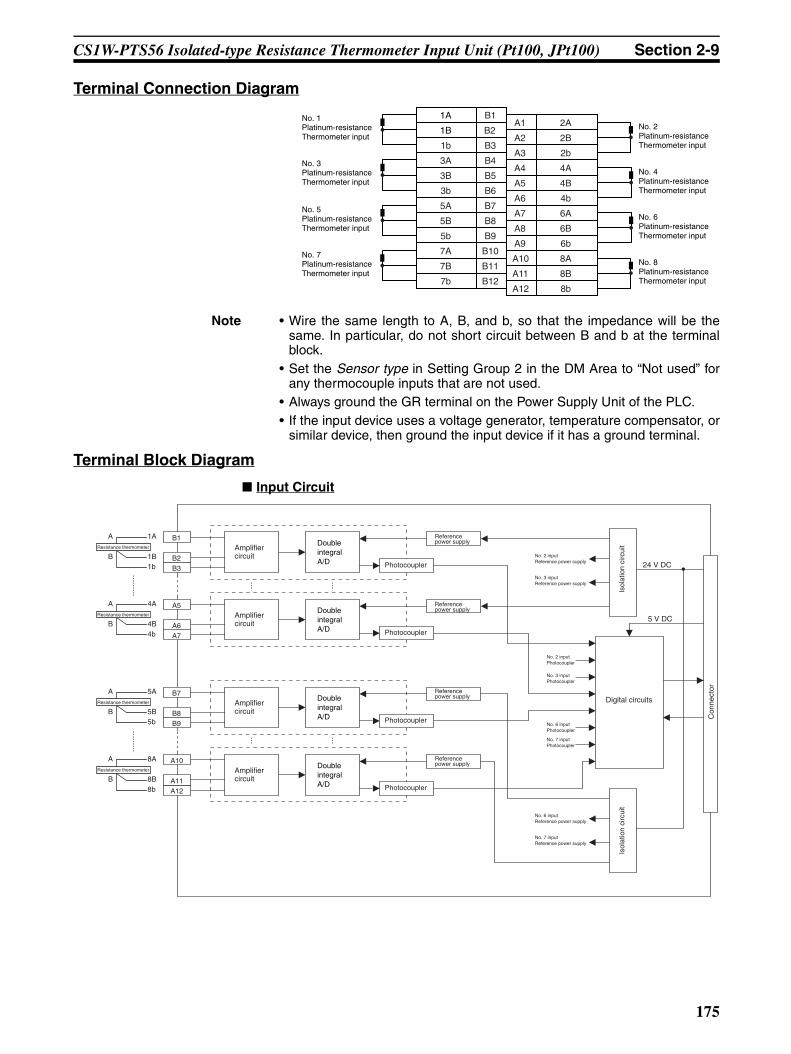
CS1W-PTS56 Isolated-type Resistance Thermometer Input Unit (Pt100, JPt100) Section 2-9
Terminal Connection Diagram
Note • Wire the same length to A, B, and b, so that the impedance will be thesame. In particular, do not short circuit between B and b at the terminalblock.
• Set the Sensor type in Setting Group 2 in the DM Area to “Not used” forany thermocouple inputs that are not used.
• Always ground the GR terminal on the Power Supply Unit of the PLC.• If the input device uses a voltage generator, temperature compensator, or
similar device, then ground the input device if it has a ground terminal.
Terminal Block Diagram
Input Circuit
1A
1B
1b
3A
3B
3b
5A
5B
5b
7A
B1
B2
B3
B4
B5
B6
B7
B8
B9
B10
A1
A2
A3
A4
A5
A6
A7
A8
A9
A10
A11
2A
2B
2b
4A
4B
4b
6A
6B
6b
8A
8B
No. 2 Platinum-resistance Thermometer input
No. 4 Platinum-resistance Thermometer input
No. 1 Platinum-resistance Thermometer input
No. 3 Platinum-resistance Thermometer input
7B
7b
B11
B12A12 8b
No. 6 Platinum-resistance Thermometer input
No. 8 Platinum-resistance Thermometer input
No. 5Platinum-resistance Thermometer input
No. 7 Platinum-resistance Thermometer input
5 V DC
Con
nect
or
Isol
atio
n ci
rcui
t
Digital circuits
1A
1B1b
A
BResistance thermometer Amplifier
circuitPhotocoupler
B1
B3B2
Double integral A/D
Reference power supply
Amplifier circuit
Photocoupler
A10
A12A11
8A
8B8b
A
BResistance thermometer
Double integral A/D
Reference power supply
Amplifier circuit
Photocoupler
B7
B9B8
5A
5B5b
A
BResistance thermometer
Double integral A/D
Reference power supply
Amplifier circuit
Photocoupler
4A
4B4b
A
BResistance thermometer
Double integral A/D
Reference power supply
A5
A7A6
Isol
atio
n ci
rcui
t
No. 2 inputPhotocoupler
No. 3 inputPhotocoupler
No. 6 inputPhotocoupler
No. 7 inputPhotocoupler
No. 2 inputReference power supply
No. 3 inputReference power supply
No. 6 inputReference power supply
No. 7 inputReference power supply
24 V DC
175

CS1W-PTS56 Isolated-type Resistance Thermometer Input Unit (Pt100, JPt100) Section 2-9
Error Processing
Conversion Data Does Not Change.
Values are Not Converted as Intended.
Converted Values are Unstable.
Probable cause Remedy
The gain for span adjustment is set to 0.
Set the gain for span adjustment to a value other than 0.
The sensor type is not set cor-rectly.
Check and reset the sensor type.
An input device is malfunctioning, input wiring is faulty, or wiring is disconnected.
Check whether the resistance has changed. Check for faulty or disconnected wiring. Check whether a sensor error has been detected in the I/O Area.
Probable cause Remedy
The sensor type, or input range is set incorrectly.
Check and reset the sensor type, input range, and the process value scaling settings.
The zero/span adjustment data is incorrect.
Check and correct the zero/span adjustment set-tings.
The platinum-resistance thermom-eter input wiring is faulty.
Check and correct the input wiring.
The compensating conductor is too long and measurements are being affected by conductor resis-tance.
Use a thicker compensating conductor.
Probable cause Remedy
Input signals are being affected by external noise.
Change the connection paths of the input signal lines. (Separate them from sources of noise or use shielded cable.)
176
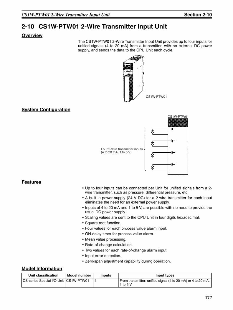
CS1W-PTW01 2-Wire Transmitter Input Unit Section 2-10
2-10 CS1W-PTW01 2-Wire Transmitter Input UnitOverview
The CS1W-PTW01 2-Wire Transmitter Input Unit provides up to four inputs forunified signals (4 to 20 mA) from a transmitter, with no external DC powersupply, and sends the data to the CPU Unit each cycle.
System Configuration
Features• Up to four inputs can be connected per Unit for unified signals from a 2-
wire transmitter, such as pressure, differential pressure, etc.• A built-in power supply (24 V DC) for a 2-wire transmitter for each input
eliminates the need for an external power supply.• Inputs of 4 to 20 mA and 1 to 5 V, are possible with no need to provide the
usual DC power supply.• Scaling values are sent to the CPU Unit in four digits hexadecimal.• Square root function.• Four values for each process value alarm input.• ON-delay timer for process value alarm.• Mean value processing.• Rate-of-change calculation.• Two values for each rate-of-change alarm input.• Input error detection.• Zero/span adjustment capability during operation.
Model Information
CS1W-PTW01
Four 2-wire transmitter inputs (4 to 20 mA, 1 to 5 V)
CS1W-PTW01
Unit classification Model number Inputs Input types
CS-series Special I/O Unit CS1W-PTW01 4 From transmitter: unified signal (4 to 20 mA) or 4 to 20 mA, 1 to 5 V
177
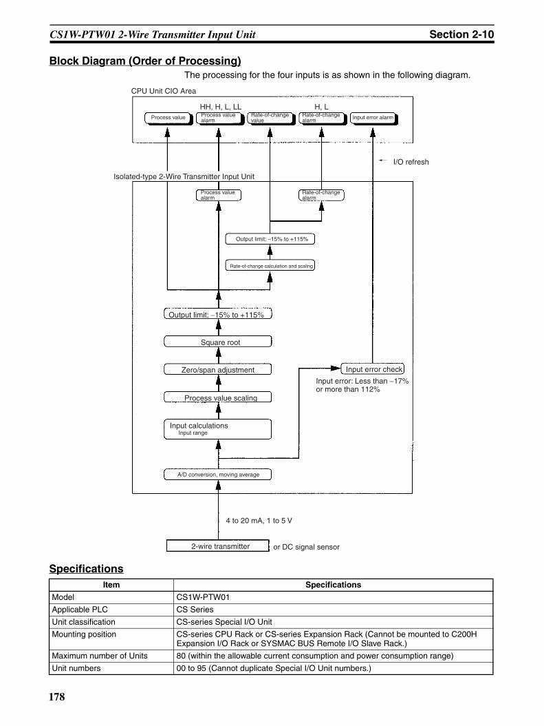
CS1W-PTW01 2-Wire Transmitter Input Unit Section 2-10
Block Diagram (Order of Processing)The processing for the four inputs is as shown in the following diagram.
SpecificationsItem Specifications
Model CS1W-PTW01
Applicable PLC CS Series
Unit classification CS-series Special I/O Unit
Mounting position CS-series CPU Rack or CS-series Expansion Rack (Cannot be mounted to C200H Expansion I/O Rack or SYSMAC BUS Remote I/O Slave Rack.)
Maximum number of Units 80 (within the allowable current consumption and power consumption range)
Unit numbers 00 to 95 (Cannot duplicate Special I/O Unit numbers.)
CPU Unit CIO Area
Process value Input error alarm
Isolated-type 2-Wire Transmitter Input Unit
Output limit: −15% to +115%
Rate-of-change calculation and scaling
Output limit: −15% to +115%
Zero/span adjustment
Process value scaling
Input calculationsInput range
A/D conversion, moving average
2-wire transmitter
Input error check
4 to 20 mA, 1 to 5 V
or DC signal sensor
I/O refresh
Square root
HH, H, L, LL H, LProcess value alarm
Rate-of-change value
Rate-of-change alarm
Process value alarm
Rate-of-change alarm
Input error: Less than −17% or more than 112%
178
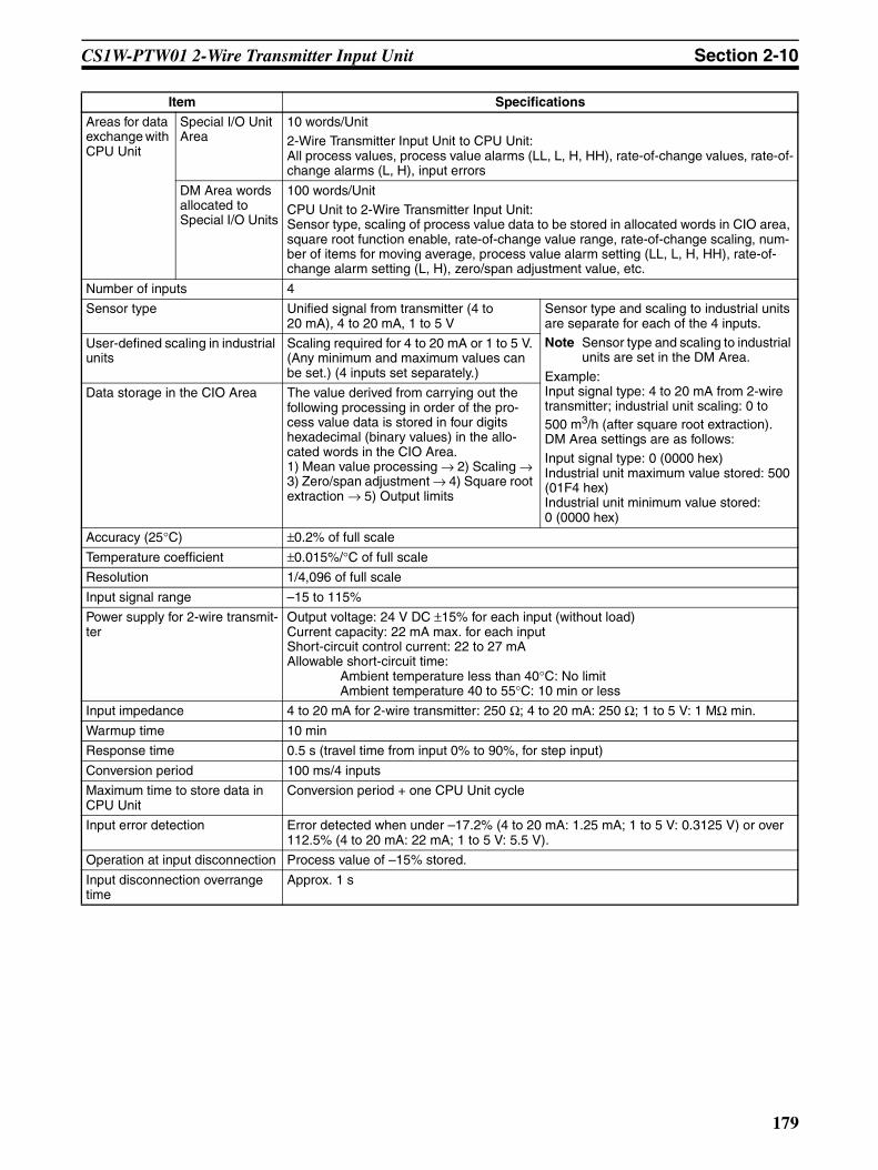
CS1W-PTW01 2-Wire Transmitter Input Unit Section 2-10
Areas for data exchange with CPU Unit
Special I/O Unit Area
10 words/Unit2-Wire Transmitter Input Unit to CPU Unit:All process values, process value alarms (LL, L, H, HH), rate-of-change values, rate-of-change alarms (L, H), input errors
DM Area words allocated to Special I/O Units
100 words/UnitCPU Unit to 2-Wire Transmitter Input Unit:Sensor type, scaling of process value data to be stored in allocated words in CIO area, square root function enable, rate-of-change value range, rate-of-change scaling, num-ber of items for moving average, process value alarm setting (LL, L, H, HH), rate-of-change alarm setting (L, H), zero/span adjustment value, etc.
Number of inputs 4
Sensor type Unified signal from transmitter (4 to 20 mA), 4 to 20 mA, 1 to 5 V
Sensor type and scaling to industrial units are separate for each of the 4 inputs.Note Sensor type and scaling to industrial
units are set in the DM Area.
Example:Input signal type: 4 to 20 mA from 2-wire transmitter; industrial unit scaling: 0 to 500 m3/h (after square root extraction). DM Area settings are as follows:Input signal type: 0 (0000 hex)Industrial unit maximum value stored: 500 (01F4 hex)Industrial unit minimum value stored: 0 (0000 hex)
User-defined scaling in industrial units
Scaling required for 4 to 20 mA or 1 to 5 V. (Any minimum and maximum values can be set.) (4 inputs set separately.)
Data storage in the CIO Area The value derived from carrying out the following processing in order of the pro-cess value data is stored in four digits hexadecimal (binary values) in the allo-cated words in the CIO Area.1) Mean value processing → 2) Scaling → 3) Zero/span adjustment → 4) Square root extraction → 5) Output limits
Accuracy (25°C) ±0.2% of full scale
Temperature coefficient ±0.015%/°C of full scale
Resolution 1/4,096 of full scale
Input signal range –15 to 115%
Power supply for 2-wire transmit-ter
Output voltage: 24 V DC ±15% for each input (without load)Current capacity: 22 mA max. for each inputShort-circuit control current: 22 to 27 mAAllowable short-circuit time:
Ambient temperature less than 40°C: No limitAmbient temperature 40 to 55°C: 10 min or less
Input impedance 4 to 20 mA for 2-wire transmitter: 250 Ω; 4 to 20 mA: 250 Ω; 1 to 5 V: 1 MΩ min.
Warmup time 10 min
Response time 0.5 s (travel time from input 0% to 90%, for step input)
Conversion period 100 ms/4 inputs
Maximum time to store data in CPU Unit
Conversion period + one CPU Unit cycle
Input error detection Error detected when under –17.2% (4 to 20 mA: 1.25 mA; 1 to 5 V: 0.3125 V) or over 112.5% (4 to 20 mA: 22 mA; 1 to 5 V: 5.5 V).
Operation at input disconnection Process value of –15% stored.
Input disconnection overrange time
Approx. 1 s
Item Specifications
179

CS1W-PTW01 2-Wire Transmitter Input Unit Section 2-10
Function Mean value pro-cessing (input filter)
Calculates the moving average for the specified number of process values (1 to 16), and stores that value in the CIO Area as the process value.
Process value alarm
Process value 4-point alarm (HH, H, LL, L), alarm hysteresis, and ON-delay timer (0 to 60 s) are available.
Rate-of-change calculation
Calculates the amount of change per comparison time interval (1 to 16 s).
Rate-of-change alarm
Rate-of-change 2-point alarm (H, L), alarm hysteresis (shared with process value alarm), and ON-delay timer (0 to 60 s, shared with process value alarm) are available.
Square root
Isolation Between inputs and between input terminals and PLC signals: Isolation by transformer
Insulation resistance 20 MΩ (at 500 V DC) between inputs
Dielectric strength Between inputs: 1,000 V AC, at 50/60 Hz, for 1 min, leakage current 10 mA max.
External connections Terminal block (detachable)
Unit number settings Set by rotary switches on front panel, from 0 to 95.
Indicators Three LED indicators on front panel (for normal operation, errors detected at the 2-Wire Transmitter Input Unit, and errors related to the CPU Unit).
Front panel connector Sensor input connector terminal block (detachable)
Effect on CPU Unit cycle time 0.3 ms
Current consumption 5 V DC at 150 mA max., 26 V DC at 160 mA max.
Dimensions 35 × 130 × 126 mm (W × H × D)Note The height including the Backplane is 145 mm.
Weight 450 g max.
Standard accessories None
Item Specifications
(A−B) (Input−B) +B
When the process value scaling maximum value is A and the minimum value is B:
Output =
Dropout: Output approx. 7% maximum linear (output = input) characteristics
Note 1 The square root function is only enabled when the maximum scaling valueis greater than the minimum value.
Note 2 When square root processing is being performed, set the maximum and minimum scaling values to the values required after square root processingof the current or other input values.
180
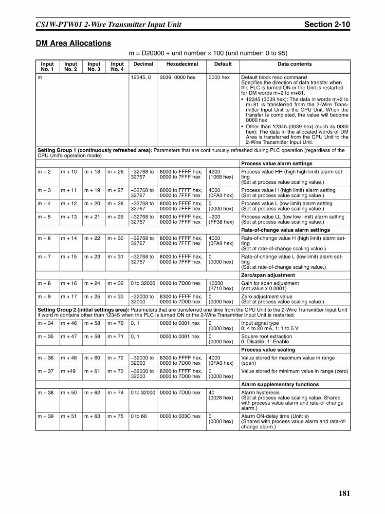
CS1W-PTW01 2-Wire Transmitter Input Unit Section 2-10
DM Area Allocationsm = D20000 + unit number × 100 (unit number: 0 to 95)
Input No. 1
Input No. 2
Input No. 3
Input No. 4
Decimal Hexadecimal Default Data contents
m 12345, 0 3039, 0000 hex 0000 hex Default block read commandSpecifies the direction of data transfer when the PLC is turned ON or the Unit is restarted for DM words m+2 to m+81.• 12345 (3039 hex): The data in words m+2 to
m+81 is transferred from the 2-Wire Trans-mitter Input Unit to the CPU Unit. When thetransfer is completed, the value will become0000 hex.
• Other than 12345 (3039 hex) (such as 0000hex): The data in the allocated words of DMArea is transferred from the CPU Unit to the2-Wire Transmitter Input Unit.
Setting Group 1 (continuously refreshed area): Parameters that are continuously refreshed during PLC operation (regardless of the CPU Unit’s operation mode)
Process value alarm settings
m + 2 m + 10 m + 18 m + 26 –32768 to 32767
8000 to FFFF hex, 0000 to 7FFF hex
4200 (1068 hex)
Process value HH (high high limit) alarm set-ting(Set at process value scaling value.)
m + 3 m + 11 m + 19 m + 27 –32768 to 32767
8000 to FFFF hex, 0000 to 7FFF hex
4000 (0FA0 hex)
Process value H (high limit) alarm setting(Set at process value scaling value.)
m + 4 m + 12 m + 20 m + 28 –32768 to 32767
8000 to FFFF hex, 0000 to 7FFF hex
0 (0000 hex)
Process value L (low limit) alarm setting(Set at process value scaling value.)
m + 5 m + 13 m + 21 m + 29 –32768 to 32767
8000 to FFFF hex, 0000 to 7FFF hex
–200 (FF38 hex)
Process value LL (low low limit) alarm setting(Set at process value scaling value.)
Rate-of-change value alarm settings
m + 6 m + 14 m + 22 m + 30 –32768 to 32767
8000 to FFFF hex, 0000 to 7FFF hex
4000 (0FA0 hex)
Rate-of-change value H (high limit) alarm set-ting(Set at rate-of-change scaling value.)
m + 7 m + 15 m + 23 m + 31 –32768 to 32767
8000 to FFFF hex, 0000 to 7FFF hex
0 (0000 hex)
Rate-of-change value L (low limit) alarm set-ting(Set at rate-of-change scaling value.)
Zero/span adjustment
m + 8 m + 16 m + 24 m + 32 0 to 32000 0000 to 7D00 hex 10000 (2710 hex)
Gain for span adjustment(set value x 0.0001)
m + 9 m + 17 m + 25 m + 33 –32000 to 32000
8300 to FFFF hex,0000 to 7D00 hex
0 (0000 hex)
Zero adjustment value(Set at process value scaling value.)
Setting Group 2 (initial settings area): Parameters that are transferred one time from the CPU Unit to the 2-Wire Transmitter Input Unit if word m contains other than 12345 when the PLC is turned ON or the 2-Wire Transmitter Input Unit is restarted.
m + 34 m + 46 m + 58 m + 70 0, 1 0000 to 0001 hex 0 (0000 hex)
Input signal type0: 4 to 20 mA, 1: 1 to 5 V
m + 35 m + 47 m + 59 m + 71 0, 1 0000 to 0001 hex 0 (0000 hex)
Square root extraction0: Disable; 1: Enable
Process value scaling
m + 36 m + 48 m + 60 m + 72 –32000 to 32000
8300 to FFFF hex, 0000 to 7D00 hex
4000 (0FA0 hex)
Value stored for maximum value in range (span)
m + 37 m +49 m + 61 m + 73 –32000 to 32000
8300 to FFFF hex, 0000 to 7D00 hex
0 (0000 hex)
Value stored for minimum value in range (zero)
Alarm supplementary functions
m + 38 m + 50 m + 62 m + 74 0 to 32000 0000 to 7D00 hex 40 (0028 hex)
Alarm hysteresis(Set at process value scaling value. Shared with process value alarm and rate-of-change alarm.)
m + 39 m + 51 m + 63 m + 75 0 to 60 0000 to 003C hex 0 (0000 hex)
Alarm ON-delay time (Unit: s)(Shared with process value alarm and rate-of-change alarm.)
181

CS1W-PTW01 2-Wire Transmitter Input Unit Section 2-10
Note The ERC indicator on the Unit’s front panel will light if an out-of-range settingis made in either Setting Group 1 or 2. The offset from word m to the first wordcontaining the out-of-range error will be stored as the Address of Data RangeError in the DM Area in four digits hexadecimal. For more information, refer to1-6 Error Processing.
Rate-of-change function
m + 40 m + 52 m + 64 m + 76 –32000 to 32000
8300 to FFFF hex, 0000 to 7D00 hex
4000 (0FA0 hex)
Rate-of-change range setting
Maximum rate-of-change value (Process value industrial unit; comparison time interval)
m + 41 m + 53 m + 65 m + 77 –32000 to 32000
8300 to FFFF hex, 0000 to 7D00 hex
–4000 (F060 hex)
Minimum rate-of-change value (Process value industrial unit; comparison time interval)
m + 42 m + 54 m + 66 m + 78 1 to 16 0001 to 0010 hex 01 (0001 hex)
Rate-of-change comparison time interval (Unit: s)
m + 43 m + 55 m + 67 m + 79 –32000 to 32000
8300 to FFFF hex, 0000 to 7D00 hex
4000 (0FA0 hex)
Rate-of-change value scaling
Value stored for maximum value in range
m + 44 m + 56 m + 68 m + 80 –32000 to 32000
8300 to FFFF hex, 0000 to 7D00 hex
0 (0000 hex)
Value stored for minimum value in range
Mean value processing function
m + 45 m + 57 m + 69 m + 81 1 to 16 0001 to 0010 hex 4 (0004 hex)
Number of process values for calculating mov-ing average for mean value processing
Storage parameter
m + 82 m + 83 m + 84 m + 85 0 to 81 0000 to 0051 hex 0 (0000 hex)
Address of Data Range Error (See note.)
Input No. 1
Input No. 2
Input No. 3
Input No. 4
Decimal Hexadecimal Default Data contents
182
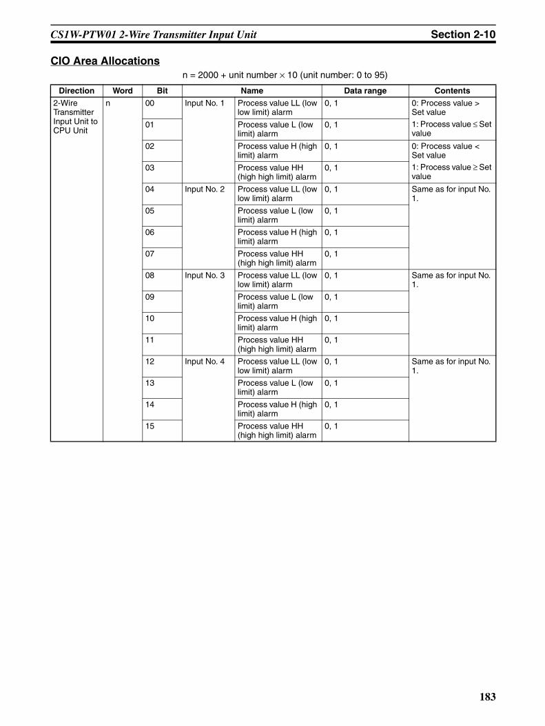
CS1W-PTW01 2-Wire Transmitter Input Unit Section 2-10
CIO Area Allocationsn = 2000 + unit number × 10 (unit number: 0 to 95)
Direction Word Bit Name Data range Contents
2-Wire Transmitter Input Unit to CPU Unit
n 00 Input No. 1 Process value LL (low low limit) alarm
0, 1 0: Process value > Set value
1: Process value ≤ Set value
01 Process value L (low limit) alarm
0, 1
02 Process value H (high limit) alarm
0, 1 0: Process value < Set value1: Process value ≥ Set value
03 Process value HH (high high limit) alarm
0, 1
04 Input No. 2 Process value LL (low low limit) alarm
0, 1 Same as for input No. 1.
05 Process value L (low limit) alarm
0, 1
06 Process value H (high limit) alarm
0, 1
07 Process value HH (high high limit) alarm
0, 1
08 Input No. 3 Process value LL (low low limit) alarm
0, 1 Same as for input No. 1.
09 Process value L (low limit) alarm
0, 1
10 Process value H (high limit) alarm
0, 1
11 Process value HH (high high limit) alarm
0, 1
12 Input No. 4 Process value LL (low low limit) alarm
0, 1 Same as for input No. 1.
13 Process value L (low limit) alarm
0, 1
14 Process value H (high limit) alarm
0, 1
15 Process value HH (high high limit) alarm
0, 1
183

CS1W-PTW01 2-Wire Transmitter Input Unit Section 2-10
2-Wire Transmitter Input Unit to CPU Unit
n + 1 00 to 15 Input No. 1 process value –32768 to 32767 (8000 to FFFF hex, 0000 to 7FFF hex)
The present process value is stored according to the scal-ing set in the allocated words of the DM Area.
n + 2 00 to 15 Input No. 2 process value –32768 to 32767 (8000 to FFFF hex, 0000 to 7FFF hex)
n + 3 00 to 15 Input No. 3 process value –32768 to 32767 (8000 to FFFF hex, 0000 to 7FFF hex)
n + 4 00 to 15 Input No. 4 process value –32768 to 32767 (8000 to FFFF hex, 0000 to 7FFF hex)
n + 5 00 to 15 Input No. 1 rate-of-change value –32768 to 32767 (8000 to FFFF hex, 0000 to 7FFF hex)
The process value rate of change is stored according to the scaling set in the allocated words of the DM Area.
n + 6 00 to 15 Input No. 2 rate-of-change value –32768 to 32767 (8000 to FFFF hex, 0000 to 7FFF hex)
n + 7 00 to 15 Input No. 3 rate-of-change value –32768 to 32767 (8000 to FFFF hex, 0000 to 7FFF hex)
n + 8 00 to 15 Input No. 4 rate-of-change value –32768 to 32767 (8000 to FFFF hex, 0000 to 7FFF hex)
n + 9 00 Input No. 1 Rate-of-change value L (low limit) alarm
0, 1 0: Rate-of-change value > Set value1: Rate-of-change value ≤ Set value
01 Rate-of-change value H (high limit) alarm
0, 1 0: Rate-of-change value < Set value
1: Rate-of-change value ≥ Set value
02 Input No. 2 Rate-of-change value L (low limit) alarm
0, 1 Same as for input No. 1.
03 Rate-of-change value H (high limit) alarm
0, 1
04 Input No. 3 Rate-of-change value L (low limit) alarm
0, 1 Same as for input No. 1.
05 Rate-of-change value H (high limit) alarm
0, 1
06 Input No. 4 Rate-of-change value L (low limit) alarm
0, 1 Same as for input No. 1.
07 Rate-of-change value H (high limit) alarm
0, 1
08 Input No. 1 input error 0, 1 0: Normal1: Error (less than –17.2% or greater than 112.5%)
09 Input No. 2 input error 0, 1 Same as for input No. 1.
10 Input No. 3 input error 0, 1 Same as for input No. 1.
11 Input No. 4 input error 0, 1 Same as for input No. 1.
Direction Word Bit Name Data range Contents
184
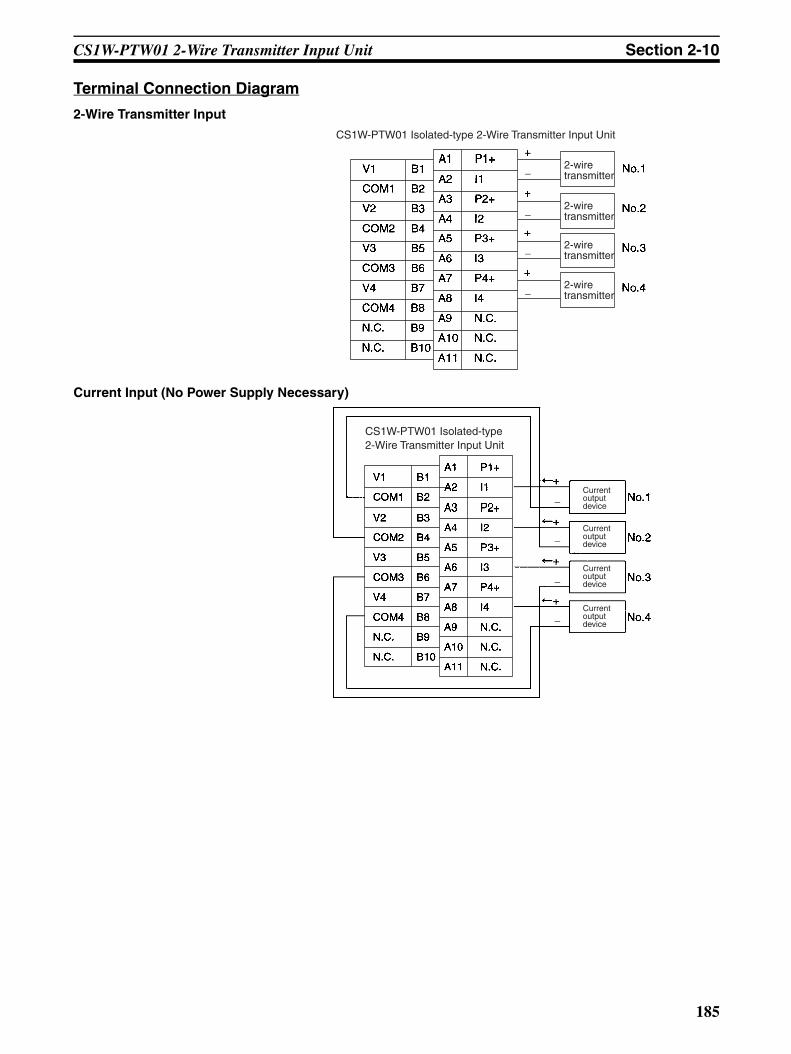
CS1W-PTW01 2-Wire Transmitter Input Unit Section 2-10
Terminal Connection Diagram
2-Wire Transmitter Input
Current Input (No Power Supply Necessary)
CS1W-PTW01 Isolated-type 2-Wire Transmitter Input Unit
2-wire transmitter
2-wire transmitter
2-wire transmitter
2-wire transmitter
−
−
−
−
CS1W-PTW01 Isolated-type 2-Wire Transmitter Input Unit
Current output device
Current output device
Current output device
Current output device
−
−
−
−
185

CS1W-PTW01 2-Wire Transmitter Input Unit Section 2-10
Voltage Input
Note In all of the above cases, leave all unused terminals open (e.g., terminals A1,A2, B1, and B2 for input No. 1).
CS1W-PTW01 Isolated-type 2-Wire Transmitter Input Unit
Voltage output device
Voltage output device
Voltage output device
Voltage output device
−
−
−
−
186
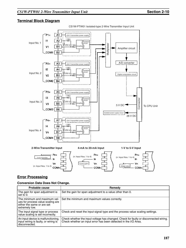
CS1W-PTW01 2-Wire Transmitter Input Unit Section 2-10
Terminal Block Diagram
Error Processing
Conversion Data Does Not Change.
Probable cause Remedy
The gain for span adjustment is set to 0.
Set the gain for span adjustment to a value other than 0.
The minimum and maximum val-ues for process value scaling are either the same or are set extremely low.
Set the minimum and maximum values correctly.
The input signal type or process value scaling is set incorrectly.
Check and reset the input signal type and the process value scaling settings.
An input device is malfunctioning, input wiring is faulty, or wiring is disconnected.
Check whether the input voltage has changed. Check for faulty or disconnected wiring. Check whether an input error has been detected in the I/O Area.
CS1W-PTW01 Isolated-type 2-Wire Transmitter Input Unit
Input No. 2
Input No. 1
Input No. 3
Input No. 4
Amplifier circuit
A/D converter
Digital computation circuit
5 V DC
26 V DCIsolated power supply circuit
To CPU Unit
Isolation circuit
Amplifier
+24-V transmitter power supply
Mul
tiple
xer
Con
nect
or
Isolation circuit
Amplifier
+24-V transmitter power supply
Isolation circuit
Amplifier
+24-V transmitter power supply
Isolation circuit
Amplifier
+24-V transmitter power supply
1 MΩ
1 MΩ
1 MΩ
1 MΩ
1 MΩ
1 MΩ
1 MΩ
1 MΩ
250 Ω
250 Ω
250 Ω
250 Ω
2-Wire Transmitter Input 4-mA to 20-mA Input 1-V to 5-V Input
2-wire transmitter
(n: Input Nos. 1 to 4)
(n: Input Nos. 1 to 4) (n: Input Nos. 1 to 4)
Current output
Voltage output
−−
−
187

CS1W-PTW01 2-Wire Transmitter Input Unit Section 2-10
Values are Not Converted as Intended.
Converted Values are Unstable.
Probable cause Remedy
The input signal type or process value scaling is set incorrectly.
Check and reset the input signal type and the process value scaling settings.
The zero/span adjustment data is incorrect.
Check and correct the zero/span adjustment settings.
The square root function is oper-ating.
Set the square function so that it does not operate.
Probable cause Remedy
Input signals are being affected by external noise.
Change the connection paths of the input signal lines. (Separate them from sources of noise or use shielded cable.)
Insert 0.01-µF to 0.1-µF ceramic capacitors between the I+ and COM, and between the V+ and COM input terminals.
Increase the number of values for calculating the moving average in mean value pro-cessing.
The scaling value is greater than the Unit’s resolution.
Reduce the scaling value.
188

CS1W-PDC01 Isolated-type Direct Current Input Unit Section 2-11
2-11 CS1W-PDC01 Isolated-type Direct Current Input UnitOverview
The CS1W-PDC01 Isolated-type Direct Current Input Unit provides four DCsignal inputs, and sends the data to the CPU Unit each cycle. All inputs areisolated.
System Configuration
Features• Up to four DC signal inputs can be connected per Unit. Any of the follow-
ing can be selected separately for the four inputs: 4 to 20 mA, 0 to 20 mA,–10 to 10 V, 0 to 10 V, –5 to 5 V, 1 to 5 V, 0 to 5 V, or ±10-V user-set range.
• Scaling values are sent to the CPU Unit in four digits hexadecimal.• Isolation between analog inputs can prevent sneak circuits from occurring
between input signals.• Square root function.• Four values for each process value alarm input.• ON-delay timer for process value alarm.• Mean value processing.• Rate-of-change calculation.• Two values for each rate-of-change alarm input.• Input error detection.• Zero/span adjustment capability during operation.
Model Information
CS1W-PDC01
Four DC inputs (−10 to 10 V, 0 to 10 V, −5 to 5 V, 0 to 5 V, 1 to 5 V, user-set V range, 4 to 20 mA, 0 to 20 mA)
CS1W-PDC01
Unit classification Model number Inputs Input types
CS-series Special I/O Unit CS1W-PDC01 4 The following can be selected separately: 4 to 20 mA, 0 to 20 mA, –10 to 10 V, 0 to 10 V, –5 to 5 V, 1 to 5 V, 0 to 5 V, or ±10-V user-set range
189
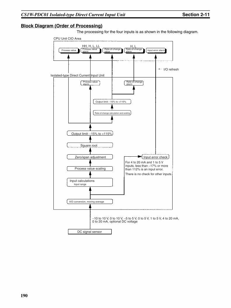
CS1W-PDC01 Isolated-type Direct Current Input Unit Section 2-11
Block Diagram (Order of Processing)The processing for the four inputs is as shown in the following diagram.
CPU Unit CIO Area
Process value Input error alarm
Isolated-type Direct Current Input Unit
Output limit: −15% to +115%
Rate-of-change calculation and scaling
Output limit: −15% to +115%
Zero/span adjustment
Process value scaling
Input calculationsInput range
A/D conversion, moving average
DC signal sensor
Input error check
−10 to 10 V, 0 to 10 V, −5 to 5 V, 0 to 5 V, 1 to 5 V, 4 to 20 mA, 0 to 20 mA, optional DC voltage
I/O refresh
Square root
There is no check for other inputs.
HH, H, L, LL H, LProcess value alarm
Rate-of-change value
Rate-of-change alarm
Process value alarm
Rate-of-change alarm
For 4 to 20 mA and 1 to 5 V inputs, less than −17% or more than 112% is an input error.
190

CS1W-PDC01 Isolated-type Direct Current Input Unit Section 2-11
SpecificationsItem Specifications
Model CS1W-PDC01
Applicable PLC CS-series
Unit classification CS-series Special I/O Unit
Mounting position CS-series CPU Rack or CS-series Expansion Rack (Cannot be mounted to C200H Expansion I/O Rack or SYSMAC BUS Remote I/O Slave Rack.)
Maximum number of Units 80 (within the allowable current consumption and power consumption range)
Unit numbers 00 to 95 (Cannot duplicate Special I/O Unit numbers.)
Areas for data exchange with CPU Unit
Special I/O Unit Area
10 words/Unit
Isolated-type Direct Current Input Unit to CPU Unit:All process values, process value alarms (LL, L, H, HH), rate-of-change values, rate-of-change alarms (L, H), input errors
DM Area words allocated to Special I/O Units
100 words/UnitCPU Unit to Isolated-type Direct Current Input Unit:Input signal type, scaling of process values in industrial units, square root function enable, rate-of-change value range, rate-of-change scaling, number of items for mov-ing average, process value alarm setting (LL, L, H, HH), rate-of-change alarm setting (L, H), zero/span adjustment value, etc.
Number of inputs 4
Input signal type 4 to 20 mA, 0 to 20 mA, –10 to 10 V, 0 to 10 V, –5 to 5 V, 1 to 5 V, 0 to 5 V, or ±10-V user-set range. The ±10-V user-set range can be specified within –10.000 to 10.000 V.
Input signal type and scaling to industrial units are separate for each of the 4 inputs.Note Input signal type and scaling to
industrial units are set in the DM Area.
Example:Input signal type: 4 to 20 mA; industrial unit scaling: 0 to 500 m3/h (after square root extraction). DM Area settings are as follows:Input signal type: 5 (0005 hex)Industrial unit maximum value stored: 500 (01F4 hex)Industrial unit minimum value stored: 0 (0000 hex)
User-defined scaling in industrial units
Scaling required for the above input sig-nals, such as 4 to 20 mA or 1 to 5 V. (Any minimum and maximum values can be set.) (4 inputs set separately.)
Data storage in the CIO Area The value derived from carrying out the following processing in order of the pro-cess value data is stored in four digits hexadecimal (binary values) in the allo-cated words in the CIO Area.1) Mean value processing → 2) Scaling → 3) Zero/span adjustment → 4) Square root extraction → 5) Output limits
Accuracy (25°C) ±0.1% of full scaleFor the ±10-V user-set range, however, as shown in the following equation, the accu-racy depends on the ratio of the selected internal range (0 to 4) span to the user-set range span.
Temperature coefficient ±0.015% /°C with respect to full scale.For the ±10-V user-set range, however: ±0.015% /°C with respect to the internal range.
Resolution 1/4,096 of full scaleFor the ±10-V user-set range, however, as shown in the following equation, the resolu-tion depends on the ratio of the selected internal range (0 to 4) span to the user-set range span.
Input signal range For inputs of 4 to 20 mA, 0 to 20 mA, 0 to 10 V, 1 to 5 V, 0 to 5 V: –15 to 115%For inputs of –10 to 10 V or –5 to 5 V: –7.5 to 107.5%For ±10-V user-set range: –7.5 to 107.5% of internal range
Maximum input rating Voltage: ±15 VCurrent: ±30 mA
Accuracy = ±0.1% x Internal range spanUser-set range span
Resolution =1
4096Internal range spanUser-set range spanx
191

CS1W-PDC01 Isolated-type Direct Current Input Unit Section 2-11
Input impedance For current input: 250 ΩFor voltage input: 1 MΩ min.
Warmup time 10 min
Response time 0.5 s (travel time from input 0% to 90%, for step input)
Conversion period 100 ms/4 inputs
Maximum time to store data in CPU Unit
Conversion period + one CPU Unit cycle
Input error detection Checks are conducted for only 4 to 20 mA and 1 to 5 V.Error detected when under –17.2% (1.25 mA, 0.3125 V) or over 112.5% (22 mA, 5.5 V).
Operation at input disconnection 4 to 20 mA, 1 to 5 V: Process value of –15% stored.0 to 20 mA, 0 to 5 V, 0 to 10 V, –10 to 10 V: The same value is stored as when 0 V or 0 mA is input.
Input disconnection overrange time
Approx. 1 s
Function Mean value pro-cessing (input filter)
Calculates the moving average for the specified number of past process values (1 to 16), and stores that value in the CIO Area as the process value.
Process value alarm
Process value 4-point alarm (HH, H, L, LL), hysteresis, and ON-delay timer (0 to 60 s) are available.
Rate-of-change calculation
Calculates the amount of change per comparison time interval (1 to 16 s).
Rate-of-change alarm
Rate-of-change 2-point alarm (H, L), alarm hysteresis (shared with process value alarm), and ON-delay timer (0 to 60 s, shared with process value alarm) are available.
Square root
Isolation Between analog inputs and between input terminals and PLC signals: Isolation by transformer
Insulation resistance 20 MΩ (at 500 V DC) between inputs
Dielectric strength Between inputs: 1,000 V AC, at 50/60 Hz, for 1 min, leakage current 10 mA max.
External connections Terminal block (detachable)
Unit number settings Set by rotary switches on front panel, from 0 to 95.
Indicators Three LED indicators on front panel (for normal operation, errors detected at the Direct Current Input Unit, and errors related to the CPU Unit).
Front panel connector Sensor input connector terminal block (detachable)
Effect on CPU Unit cycle time 0.3 ms
Current consumption 5 V DC at 150 mA max., 26 V DC at 160 mA max.
Dimensions 35 × 130 × 126 mm (W × H × D)Note The height including the Backplane is 145 mm.
Weight 450 g max.
Standard accessories None
Item Specifications
(A−B) (Input−B) +B
When the process value scaling maximum value is A and the minimum value is B:
Output =
Dropout: Output approx. 7% maximum linear (output = input) characteristics
Note The square root function is only enabled when the maximum scaling value is greater than the minimum value.
Note When square root processing is being performed, set the maximum and mini-mum scaling values to the values required after square root processing of the current or other input values.
192

CS1W-PDC01 Isolated-type Direct Current Input Unit Section 2-11
Accuracy and Resolution for ±10 V User-set RangeWith the ±10-V user-set range, the input signal zero and span can be set any-where within the range –10.000 to 10.000 V. Internally, however, inputs areprocessed in five progressive ranges (numbers 0 to 4), as shown in the follow-ing table.
Table 1: Internal Ranges
Therefore, the accuracy and resolution of the set range span are determinedby the ratio of the internal range (0 to 4) span to the set input range span. Forthe internal range, a larger number is selected when both the minimum andmaximum values of the range fall within that next range.For example, suppose that the set input range is 0.000 to 3.000 V. Since boththe minimum and maximum values fall within the limits for internal range No. 1(–5.000 to 5.000 V), that range will be selected.
DM Area Allocationsm = D20000 + unit number × 100 (unit number: 0 to 95)
Internal range number Measurable voltage Internal range span
0 –10.000 to 10.000 V 20.000 V
1 –5.000 to 5.000 V 10.000 V
2 –2.500 to 2.500 V 5.000 V
3 –1.250 to 1.250 V 2.500 V
4 –0.625 to 0.625 V 1.250 V
Input No. 1
Input No. 2
Input No. 3
Input No. 4
Decimal Hexadecimal Default Data contents
m 12345, 0 3039, 0000 hex 0000 hex Default block read commandSpecifies the direction of data transfer when the PLC is turned ON or the Unit is restarted for DM words m+2 to m+89.• 12345 (3039 hex): The data in words m+2 to
m+89 is transferred from the Direct CurrentInput Unit to the CPU Unit. When the transferis completed, the value will become 0000hex.
• Other than 12345 (3039 hex) (such as 0000hex): The data in the allocated words of DMArea is transferred from the CPU Unit to theDirect Current Input Unit.
Setting Group 1 (continuously refreshed area): Parameters that are continuously refreshed during PLC operation (regardless of the CPU Unit’s operation mode)
Process value alarm settings
m + 2 m + 10 m + 18 m + 26 –32768 to 32767
8000 to FFFF hex, 0000 to 7FFF hex
4200 (1068 hex)
Process value HH (high high limit) alarm set-ting(Set at process value scaling value.)
m + 3 m + 11 m + 19 m + 27 –32768 to 32767
8000 to FFFF hex, 0000 to 7FFF hex
4000 (0FA0 hex)
Process value H (high limit) alarm setting(Set at process value scaling value.)
m + 4 m + 12 m + 20 m + 28 –32768 to 32767
8000 to FFFF hex, 0000 to 7FFF hex
0 (0000 hex)
Process value L (low limit) alarm setting(Set at process value scaling value.)
m + 5 m + 13 m + 21 m + 29 –32768 to 32767
8000 to FFFF hex, 0000 to 7FFF hex
–200 (FF38 hex)
Process value LL (low low limit) alarm setting(Set at process value scaling value.)
Rate-of-change value alarm settings
m + 6 m + 14 m + 22 m + 30 –32768 to 32767
8000 to FFFF hex, 0000 to 7FFF hex
4000 (0FA0 hex)
Rate-of-change value H (high limit) alarm set-ting(Set at rate-of-change scaling value.)
m + 7 m + 15 m + 23 m + 31 –32768 to 32767
8000 to FFFF hex, 0000 to 7FFF hex
0 (0000 hex)
Rate-of-change value L (low limit) alarm set-ting(Set at rate-of-change scaling value.)
Zero/span adjustment
m + 8 m + 16 m + 24 m + 32 0 to 32000 0000 to 7D00 hex 10000 (2710 hex)
Gain for span adjustment(set value x 0.0001)
m + 9 m + 17 m + 25 m + 33 –32000 to 32000
8300 to FFFF hex,0000 to 7D00 hex
0 (0000 hex)
Zero adjustment value(Set at process value scaling value.)
193
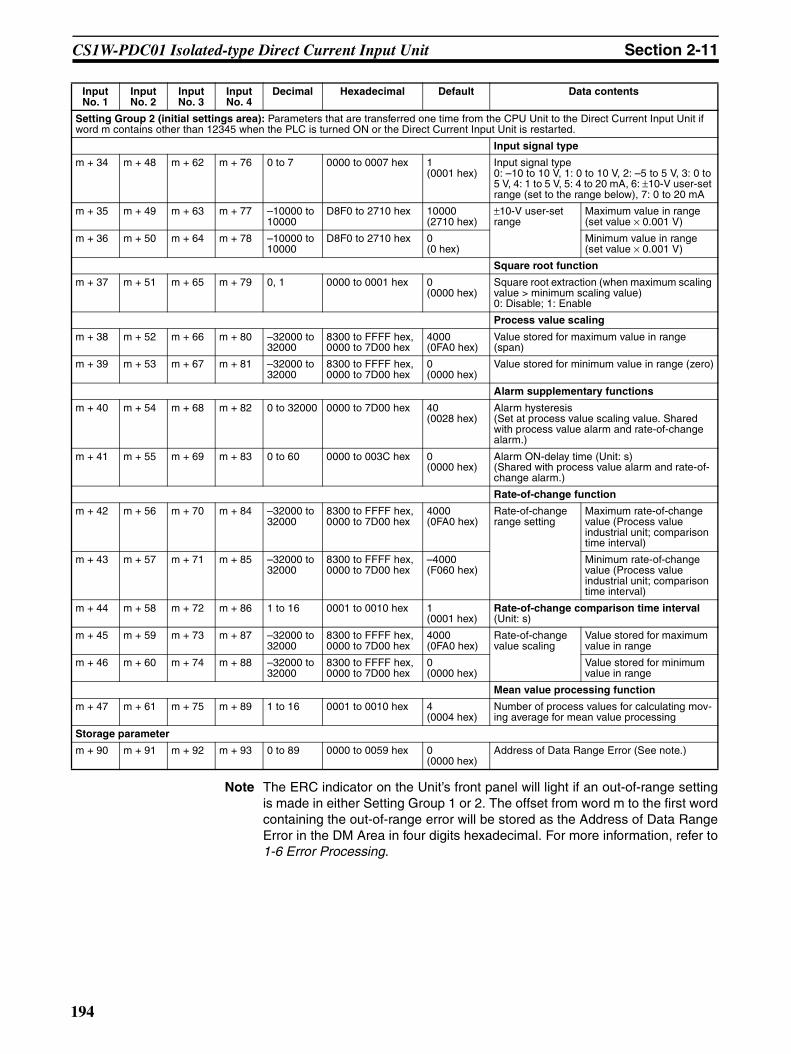
CS1W-PDC01 Isolated-type Direct Current Input Unit Section 2-11
Note The ERC indicator on the Unit’s front panel will light if an out-of-range settingis made in either Setting Group 1 or 2. The offset from word m to the first wordcontaining the out-of-range error will be stored as the Address of Data RangeError in the DM Area in four digits hexadecimal. For more information, refer to1-6 Error Processing.
Setting Group 2 (initial settings area): Parameters that are transferred one time from the CPU Unit to the Direct Current Input Unit if word m contains other than 12345 when the PLC is turned ON or the Direct Current Input Unit is restarted.
Input signal type
m + 34 m + 48 m + 62 m + 76 0 to 7 0000 to 0007 hex 1 (0001 hex)
Input signal type0: –10 to 10 V, 1: 0 to 10 V, 2: –5 to 5 V, 3: 0 to 5 V, 4: 1 to 5 V, 5: 4 to 20 mA, 6: ±10-V user-set range (set to the range below), 7: 0 to 20 mA
m + 35 m + 49 m + 63 m + 77 –10000 to 10000
D8F0 to 2710 hex 10000 (2710 hex)
±10-V user-set range
Maximum value in range (set value × 0.001 V)
m + 36 m + 50 m + 64 m + 78 –10000 to 10000
D8F0 to 2710 hex 0 (0 hex)
Minimum value in range (set value × 0.001 V)
Square root function
m + 37 m + 51 m + 65 m + 79 0, 1 0000 to 0001 hex 0 (0000 hex)
Square root extraction (when maximum scaling value > minimum scaling value)0: Disable; 1: Enable
Process value scaling
m + 38 m + 52 m + 66 m + 80 –32000 to 32000
8300 to FFFF hex, 0000 to 7D00 hex
4000 (0FA0 hex)
Value stored for maximum value in range (span)
m + 39 m + 53 m + 67 m + 81 –32000 to 32000
8300 to FFFF hex, 0000 to 7D00 hex
0 (0000 hex)
Value stored for minimum value in range (zero)
Alarm supplementary functions
m + 40 m + 54 m + 68 m + 82 0 to 32000 0000 to 7D00 hex 40 (0028 hex)
Alarm hysteresis(Set at process value scaling value. Shared with process value alarm and rate-of-change alarm.)
m + 41 m + 55 m + 69 m + 83 0 to 60 0000 to 003C hex 0 (0000 hex)
Alarm ON-delay time (Unit: s)(Shared with process value alarm and rate-of-change alarm.)
Rate-of-change function
m + 42 m + 56 m + 70 m + 84 –32000 to 32000
8300 to FFFF hex, 0000 to 7D00 hex
4000 (0FA0 hex)
Rate-of-change range setting
Maximum rate-of-change value (Process value industrial unit; comparison time interval)
m + 43 m + 57 m + 71 m + 85 –32000 to 32000
8300 to FFFF hex, 0000 to 7D00 hex
–4000 (F060 hex)
Minimum rate-of-change value (Process value industrial unit; comparison time interval)
m + 44 m + 58 m + 72 m + 86 1 to 16 0001 to 0010 hex 1 (0001 hex)
Rate-of-change comparison time interval (Unit: s)
m + 45 m + 59 m + 73 m + 87 –32000 to 32000
8300 to FFFF hex, 0000 to 7D00 hex
4000 (0FA0 hex)
Rate-of-change value scaling
Value stored for maximum value in range
m + 46 m + 60 m + 74 m + 88 –32000 to 32000
8300 to FFFF hex, 0000 to 7D00 hex
0 (0000 hex)
Value stored for minimum value in range
Mean value processing function
m + 47 m + 61 m + 75 m + 89 1 to 16 0001 to 0010 hex 4 (0004 hex)
Number of process values for calculating mov-ing average for mean value processing
Storage parameter
m + 90 m + 91 m + 92 m + 93 0 to 89 0000 to 0059 hex 0 (0000 hex)
Address of Data Range Error (See note.)
Input No. 1
Input No. 2
Input No. 3
Input No. 4
Decimal Hexadecimal Default Data contents
194

CS1W-PDC01 Isolated-type Direct Current Input Unit Section 2-11
CIO Area Allocationsn = 2000 + unit number × 10 (unit number: 0 to 95)
Direction Word Bit Name Data range Contents
Direct Cur-rent Input Unit to CPU Unit
n 00 Input No. 1 Process value LL (low low limit) alarm
0, 1 0: Process value > Set value
1: Process value ≤ Set value
01 Process value L (low limit) alarm
0, 1
02 Process value H (high limit) alarm
0, 1 0: Process value < Set value1: Process value ≥ Set value
03 Process value HH (high high limit) alarm
0, 1
04 Input No. 2 Process value LL (low low limit) alarm
0, 1 Same as for input No. 1.
05 Process value L (low limit) alarm
0, 1
06 Process value H (high limit) alarm
0, 1
07 Process value HH (high high limit) alarm
0, 1
08 Input No. 3 Process value LL (low low limit) alarm
0, 1 Same as for input No. 1.
09 Process value L (low limit) alarm
0, 1
10 Process value H (high limit) alarm
0, 1
11 Process value HH (high high limit) alarm
0, 1
12 Input No. 4 Process value LL (low low limit) alarm
0, 1 Same as for input No. 1.
13 Process value L (low limit) alarm
0, 1
14 Process value H (high limit) alarm
0, 1
15 Process value HH (high high limit) alarm
0, 1
195

CS1W-PDC01 Isolated-type Direct Current Input Unit Section 2-11
Direct Cur-rent Input Unit to CPU Unit
n + 1 00 to 15 Input No. 1 process value –32768 to 32767 (8000 to FFFF hex, 0000 to 7FFF hex)
The present process value is stored according to the scaling set in the allocated words of the DM Area.
n + 2 00 to 15 Input No. 2 process value –32768 to 32767 (8000 to FFFF hex, 0000 to 7FFF hex)
n + 3 00 to 15 Input No. 3 process value –32768 to 32767 (8000 to FFFF hex, 0000 to 7FFF hex)
n + 4 00 to 15 Input No. 4 process value –32768 to 32767 (8000 to FFFF hex, 0000 to 7FFF hex)
n + 5 00 to 15 Input No. 1 rate-of-change value –32768 to 32767 (8000 to FFFF hex, 0000 to 7FFF hex)
The process value rate of change is stored accord-ing to the scaling set in the allocated words of the DM Area.
n + 6 00 to 15 Input No. 2 rate-of-change value –32768 to 32767 (8000 to FFFF hex, 0000 to 7FFF hex)
n + 7 00 to 15 Input No. 3 rate-of-change value –32768 to 32767 (8000 to FFFF hex, 0000 to 7FFF hex)
n + 8 00 to 15 Input No. 4 rate-of-change value –32768 to 32767 (8000 to FFFF hex, 0000 to 7FFF hex)
n + 9 00 Input No. 1 Rate-of-change value L (low limit) alarm
0, 1 0: Rate-of-change value > Set value1: Rate-of-change value ≤ Set value
01 Rate-of-change value H (high limit) alarm
0, 1 0: Rate-of-change value < Set value
1: Rate-of-change value ≥ Set value
02 Input No. 2 Rate-of-change value L (low limit) alarm
0, 1 Same as for input No. 1.
03 Rate-of-change value H (high limit) alarm
0, 1
04 Input No. 3 Rate-of-change value L (low limit) alarm
0, 1 Same as for input No. 1.
05 Rate-of-change value H (high limit) alarm
0, 1
06 Input No. 4 Rate-of-change value L (low limit) alarm
0, 1 Same as for input No. 1.
07 Rate-of-change value H (high limit) alarm
0, 1
08 Input No. 1 input error 0, 1 0: Normal1: Error (less than –17.2% or greater than 112.5%)Note Checks are con-
ducted for inputs of 4 to 20 mA and 1 to 5 V.
09 Input No. 2 input error 0, 1 Same as for input No. 1.
10 Input No. 3 input error 0, 1 Same as for input No. 1.
11 Input No. 4 input error 0, 1 Same as for input No. 1.
Direction Word Bit Name Data range Contents
196

CS1W-PDC01 Isolated-type Direct Current Input Unit Section 2-11
Terminal Connection Diagram
Note In both of the above cases, leave all unused inputs open between the positiveand negative terminals (e.g., between B1 and B2 for voltage input No. 1).
Current inputVoltage input
Voltage output device Current output
device
Voltage output device
Voltage output device
Voltage output device
Current output device
Current output device
Current output device
−
−
−
−
−
−
−
−
197

CS1W-PDC01 Isolated-type Direct Current Input Unit Section 2-11
Terminal Block Diagram
Error Processing
Conversion Data Does Not Change.
Input No. 2
Input No. 1
Input No. 3
Input No. 4
Multi-gain amplifier circuit
A/D converter
Digital computation circuit
5 V DC
26 V DCIsolated power supply circuit
To CPU Unit
Isolation circuit
Amplifier
Isolation circuit
Amplifier
Isolation circuit
Amplifier
Isolation circuit
Amplifier
Mul
tiple
xer
Con
nect
or
1 MΩ
1 MΩ
1 MΩ
1 MΩ
250 Ω
250 Ω
250 Ω
250 Ω
1 MΩ
1 MΩ
1 MΩ
1 MΩ
(n: Input Nos. 1 to 4) (n: Input Nos. 1 to 4)
Current input Voltage input
Current output
Voltage output
Probable cause Remedy
The gain for span adjustment is set to 0.
Set the gain for span adjustment to a value other than 0.
The minimum and maximum val-ues for process value scaling are either the same or are set extremely low.
Set the minimum and maximum values correctly.
The input signal type or process value range is set incorrectly.
Check and reset the input signal type and the process value range settings.
An input device is malfunctioning, input wiring is faulty, or wiring is disconnected.
Check whether the input voltage has changed. Check for faulty or disconnected wiring. Check whether an input error has been detected in the I/O Area.
198

CS1W-PDC01 Isolated-type Direct Current Input Unit Section 2-11
Values are Not Converted as Intended.
Converted Values are Unstable.
Probable cause Remedy
The input signal type or process value scaling is set incorrectly.
Check and reset the input signal type and the process value scaling settings.
The zero/span adjustment data is incorrect.
Check and correct the zero/span adjustment settings.
The square root function is oper-ating.
Set the square function so that it does not operate.
Probable cause Remedy
Input signals are being affected by external noise.
Change the connection paths of the input signal lines. (Separate them from sources of noise or use shielded cable.)
Insert 0.01-µF to 0.1-µF ceramic capacitors between the I+ and COM, and between the V+ and COM input terminals.
Increase the number of values for calculating the moving average in mean value pro-cessing.
The scaling value is greater than the Unit’s resolution.
Reduce the scaling value.
199
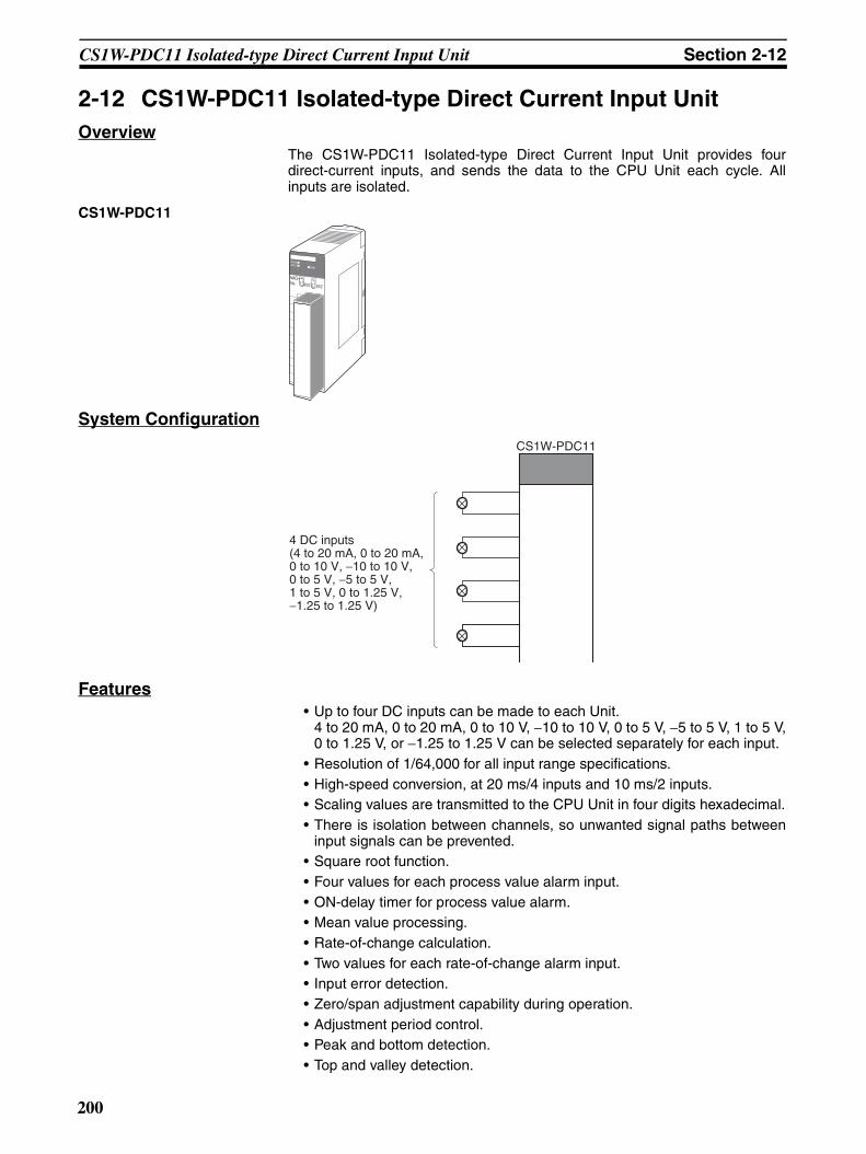
CS1W-PDC11 Isolated-type Direct Current Input Unit Section 2-12
2-12 CS1W-PDC11 Isolated-type Direct Current Input UnitOverview
The CS1W-PDC11 Isolated-type Direct Current Input Unit provides fourdirect-current inputs, and sends the data to the CPU Unit each cycle. Allinputs are isolated.
CS1W-PDC11
System Configuration
Features• Up to four DC inputs can be made to each Unit.
4 to 20 mA, 0 to 20 mA, 0 to 10 V, −10 to 10 V, 0 to 5 V, −5 to 5 V, 1 to 5 V,0 to 1.25 V, or −1.25 to 1.25 V can be selected separately for each input.
• Resolution of 1/64,000 for all input range specifications.• High-speed conversion, at 20 ms/4 inputs and 10 ms/2 inputs.• Scaling values are transmitted to the CPU Unit in four digits hexadecimal.• There is isolation between channels, so unwanted signal paths between
input signals can be prevented.• Square root function.• Four values for each process value alarm input.• ON-delay timer for process value alarm.• Mean value processing.• Rate-of-change calculation.• Two values for each rate-of-change alarm input.• Input error detection.• Zero/span adjustment capability during operation.• Adjustment period control.• Peak and bottom detection.• Top and valley detection.
MACHNo.
X100
FEDCBA9876543210 FEDCBA9876543
210X101
RUNERC
ERH
CS1W-PDC11
4 DC inputs(4 to 20 mA, 0 to 20 mA, 0 to 10 V, −10 to 10 V, 0 to 5 V, −5 to 5 V, 1 to 5 V, 0 to 1.25 V, −1.25 to 1.25 V)
200

CS1W-PDC11 Isolated-type Direct Current Input Unit Section 2-12
• Integral value calculation.
Model InformationUnit classification Model number Inputs Input types
CS-series Special I/O Unit
CS1W-PDC11 4 4 to 20 mA, 0 to 20 mA, 0 to 10 V, −10 to 10 V, 0 to 5 V, −5 to 5 V, 1 to 5 V, 0 to 1.25 V, and −1.25 to 1.25 V (separate for each input)
201

CS1W-PDC11 Isolated-type Direct Current Input Unit Section 2-12
Block Diagram
Rate-of-change alarm
Output limit: −15% to +115%
Rate-of-change calculation and scaling
+115% or −15% when input disconnection is detected
Square root
Zero/span adjustment
Process value scaling
Input calculationsInput range
A/D conversion, moving average
DC signal sensor
Input error check
HH, H, L, LL H, L
Top/valley value
CPU Unit
CPU Unit Expansion Area Allocations
I/O refresh
Peak/Bottom value
Process value Process value alarm Rate-of-change value Rate-of-change alarm Input error alarm
CPU Unit CIO Area
Isolated-type Direct Current Input Unit
Process value alarm
There is no check for other inputs.
For 4 to 20 mA and 1 to 5 V inputs, less than −17% or more than 112% is an input error.
202
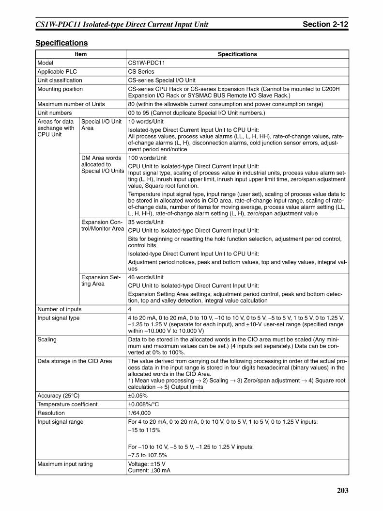
CS1W-PDC11 Isolated-type Direct Current Input Unit Section 2-12
SpecificationsItem Specifications
Model CS1W-PDC11
Applicable PLC CS Series
Unit classification CS-series Special I/O Unit
Mounting position CS-series CPU Rack or CS-series Expansion Rack (Cannot be mounted to C200H Expansion I/O Rack or SYSMAC BUS Remote I/O Slave Rack.)
Maximum number of Units 80 (within the allowable current consumption and power consumption range)
Unit numbers 00 to 95 (Cannot duplicate Special I/O Unit numbers.)
Areas for data exchange with CPU Unit
Special I/O Unit Area
10 words/Unit
Isolated-type Direct Current Input Unit to CPU Unit:All process values, process value alarms (LL, L, H, HH), rate-of-change values, rate-of-change alarms (L, H), disconnection alarms, cold junction sensor errors, adjust-ment period end/notice
DM Area words allocated to Special I/O Units
100 words/Unit
CPU Unit to Isolated-type Direct Current Input Unit:Input signal type, scaling of process value in industrial units, process value alarm set-ting (L, H), inrush input upper limit, inrush input upper limit time, zero/span adjustment value, Square root function.Temperature input signal type, input range (user set), scaling of process value data to be stored in allocated words in CIO area, rate-of-change input range, scaling of rate-of-change data, number of items for moving average, process value alarm setting (LL, L, H, HH), rate-of-change alarm setting (L, H), zero/span adjustment value
Expansion Con-trol/Monitor Area
35 words/Unit
CPU Unit to Isolated-type Direct Current Input Unit:Bits for beginning or resetting the hold function selection, adjustment period control, control bits
Isolated-type Direct Current Input Unit to CPU Unit:Adjustment period notices, peak and bottom values, top and valley values, integral val-ues
Expansion Set-ting Area
46 words/UnitCPU Unit to Isolated-type Direct Current Input Unit:
Expansion Setting Area settings, adjustment period control, peak and bottom detec-tion, top and valley detection, integral value calculation
Number of inputs 4
Input signal type 4 to 20 mA, 0 to 20 mA, 0 to 10 V, −10 to 10 V, 0 to 5 V, −5 to 5 V, 1 to 5 V, 0 to 1.25 V, −1.25 to 1.25 V (separate for each input), and ±10-V user-set range (specified range within –10.000 V to 10.000 V)
Scaling Data to be stored in the allocated words in the CIO area must be scaled (Any mini-mum and maximum values can be set.) (4 inputs set separately.) Data can be con-verted at 0% to 100%.
Data storage in the CIO Area The value derived from carrying out the following processing in order of the actual pro-cess data in the input range is stored in four digits hexadecimal (binary values) in the allocated words in the CIO Area.1) Mean value processing → 2) Scaling → 3) Zero/span adjustment → 4) Square root calculation → 5) Output limits
Accuracy (25°C) ±0.05%
Temperature coefficient ±0.008%/°CResolution 1/64,000
Input signal range For 4 to 20 mA, 0 to 20 mA, 0 to 10 V, 0 to 5 V, 1 to 5 V, 0 to 1.25 V inputs:−15 to 115%
For −10 to 10 V, −5 to 5 V, −1.25 to 1.25 V inputs: −7.5 to 107.5%
Maximum input rating Voltage: ±15 VCurrent: ±30 mA
203
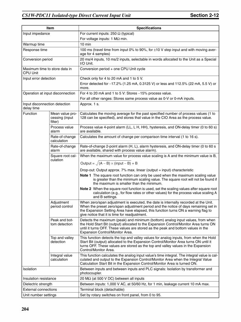
CS1W-PDC11 Isolated-type Direct Current Input Unit Section 2-12
Input impedance For current inputs: 250 Ω (typical)For voltage inputs: 1 MΩ min.
Warmup time 10 min
Response time 100 ms (travel time from input 0% to 90%, for ±10 V step input and with moving aver-age for 4 samples)
Conversion period 20 ms/4 inputs, 10 ms/2 inputs, selectable in words allocated to the Unit as a Special I/O Unit.
Maximum time to store data in CPU Unit
Conversion period + one CPU Unit cycle
Input error detection Check only for 4 to 20 mA and 1 to 5 V.Error detected for −17.2% (1.25 mA, 0.3125 V) or less and 112.5% (22 mA, 5.5 V) or more.
Operation at input disconnection For 4 to 20 mA and 1 to 5 V: Stores −15% process value.For all other ranges: Stores same process value as 0-V or 0-mA inputs.
Input disconnection detection delay time
Approx. 1 s.
Function Mean value pro-cessing (input filter)
Calculates the moving average for the past specified number of process values (1 to 128 can be specified), and stores that value in the CIO Area as the process value.
Process value alarm
Process value 4-point alarm (LL, L H, HH), hysteresis, and ON-delay timer (0 to 60 s) are available.
Rate-of-change calculation
Calculates the amount of change per comparison time interval (1 to 16 s).
Rate-of-change alarm
Rate-of-change 2-point alarm (H, L), alarm hysteresis, and ON-delay timer (0 to 60 s are available, shared with process value alarm).
Square root cal-culation
When the maximum value for process value scaling is A and the minimum value is B,
Drop-out: Output approx. 7% max. linear (output = input) characteristic
Note 1 The square root function can only be used when the maximum scaling value is greater than the minimum scaling value. The square root will not be found if the maximum is smaller than the minimum.
Note 2 When the square root function is used, set the scaling values after square root calculation (e.g., for flow rates or other values) for the process value scaling A and B settings.
Adjustment period control
When zero/span adjustment is executed, the date is internally recorded at the Unit. When the preset zero/span adjustment period and the notice of days remaining set in the Expansion Setting Area have elapsed, this function turns ON a warning flag to give notice that it is time for readjustment.
Peak and bot-tom detection
Detects the maximum (peak) and minimum (bottom) analog input values, from when the Hold Start Bit (output) allocated to the Expansion Control/Monitor Area turns ON until it turns OFF. These values are stored as the peak and bottom values in the Expansion Control/Monitor Area.
Top and valley detection
This function detects the top and valley values for analog inputs, from when the Hold Start Bit (output) allocated to the Expansion Control/Monitor Area turns ON until it turns OFF. These values are stored as the top and valley values in the Expansion Control/Monitor Area.
Integral value calculation
This function calculates the analog input value’s time integral. The integral value is cal-culated and output to the Expansion Control/Monitor Area when the Integral Value Calculation Start Bit in the Expansion Control/Monitor Area is turned ON.
Isolation Between inputs and between inputs and PLC signals: Isolation by transformer and photocoupler.
Insulation resistance 20 MΩ (at 500 V DC) between all inputs
Dielectric strength Between inputs: 1,000 V AC, at 50/60 Hz, for 1 min, leakage current 10 mA max.
External connections Terminal block (detachable)
Unit number settings Set by rotary switches on front panel, from 0 to 95.
Item Specifications
(A − B) × (input − B) + BOutput =
204
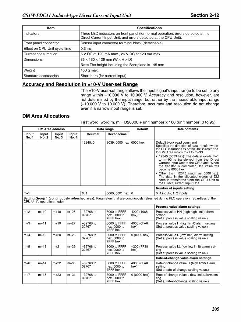
CS1W-PDC11 Isolated-type Direct Current Input Unit Section 2-12
Accuracy and Resolution in ±10-V User-set RangeThe ±10-V user-set range allows the input signal’s input range to be set to anyrange within –10.000 V to 10.000 V. Accuracy and resolution, however, arenot determined by the input range, but rather by the measurable input range(–10.000 V to 10.000 V). Therefore, accuracy and resolution do not changeeven if a narrow input range is set.
DM Area AllocationsFirst word: word m. m = D20000 + unit number × 100 (unit number: 0 to 95)
Indicators Three LED indicators on front panel (for normal operation, errors detected at the Direct Current Input Unit, and errors detected at the CPU Unit).
Front panel connector Sensor input connector terminal block (detachable)
Effect on CPU Unit cycle time 0.3 ms
Current consumption 5 V DC at 120 mA max., 26 V DC at 120 mA max.
Dimensions 35 × 130 × 126 mm (W × H × D)
Note The height including the Backplane is 145 mm.
Weight 450 g max.
Standard accessories Short bars (for current input)
Item Specifications
DM Area address Data range Default Data contents
Input No. 1
Input No. 2
Input No. 3
Input No. 4
Decimal Hexadecimal
m 12345, 0 3039, 0000 hex 0000 hex Default block read commandSpecifies the direction of data transfer when the PLC is turned ON or the Unit is restarted for DM Area words m+1 to m+93.• 12345 (3039 hex): The data in words m+1
to m+93 is transferred from the DirectCurrent Input Unit to the CPU Unit. Whenthe transfer is completed, the value willbecome 0000 hex.
• Other than 12345 (such as 0000 hex):The data in the allocated words of DMArea is transferred from the CPU Unit tothe Direct Current Input Unit.
Number of inputs setting
m+1 0, 1 0000, 0001 hex 0 0: 4 inputs; 1: 2 inputs
Setting Group 1 (continuously refreshed area): Parameters that are continuously refreshed during PLC operation (regardless of the CPU Unit’s operation mode)
Process value alarm settings
m+2 m+10 m+18 m+26 –32768 to 32767
8000 to FFFF hex, 0000 to 7FFF hex
4200 (1068 hex)
Process value HH (high high limit) alarm setting(Set at process value scaling value.)
m+3 m+11 m+19 m+27 –32768 to 32767
8000 to FFFF hex, 0000 to 7FFF hex
4000 (0FA0 hex)
Process value H (high limit) alarm setting(Set at process value scaling value.)
m+4 m+12 m+20 m+28 –32768 to 32767
8000 to FFFF hex, 0000 to 7FFF hex
0 (0000 hex) Process value L (low limit) alarm setting(Set at process value scaling value.)
m+5 m+13 m+21 m+29 –32768 to 32767
8000 to FFFF hex, 0000 to 7FFF hex
–200 (FF38 hex)
Process value LL (low low limit) alarm set-ting(Set at process value scaling value.)
Rate-of-change value alarm settings
m+6 m+14 m+22 m+30 –32768 to 32767
8000 to FFFF hex, 0000 to 7FFF hex
4000 (0FA0 hex)
Rate-of-change value H (high limit) alarm setting(Set at rate-of-change scaling value.)
m+7 m+15 m+23 m+31 –32768 to 32767
8000 to FFFF hex, 0000 to 7FFF hex
0 (0000 hex) Rate-of-change value L (low limit) alarm set-ting(Set at rate-of-change scaling value.)
205

CS1W-PDC11 Isolated-type Direct Current Input Unit Section 2-12
Zero/span adjustment
m+8 m+16 m+24 m+32 0 to 32000 0000 to 7D00 hex
10000 (2710 hex)
Gain for span adjustment(set value × 0.0001%)
m+9 m+17 m+25 m+33 –32000 to 32000
8300 to FFFF hex, 0000 to 7D00 hex
0 (0000 hex) Zero adjustment value(Set at process value scaling value.)
Setting Group 2 (initial settings area): Parameters that are transferred one time from the CPU Unit to the Direct Current Input Unit if word m contains other than 12345 when the PLC is turned ON or the Direct Current Input Unit is restarted.
Input signal type
m+34 m+48 m+62 m+76 0 to 9 0000 to 0009 hex
1 (0001 hex) 0: ±10 V; 1: 0 to 10 V; 2: ±5 V; 3: 0 to 5 V; 4: 1 to 5 V; 5: 4 to 20 mA; 6: ±10 V user-set range; 7: 0 to 20 mA; 8: ±1.25 V; 9: 0 to 1.25 V
Process value input range
m+35 m+49 m+63 m+77 –1000 to 1000 D8F0 to FFFF hex, 0000 to 2710 hex
10000 (2710 hex)
±10-V user-set range
Maximum value in range (set value × 0.001 V)
m+36 m+50 m+64 m+78 –1000 to 1000 D8F0 to FFFF hex, 0000 to 2710 hex
0 (0000 hex) Minimum value in range (set value × 0.001 V)
Square root function
m+37 m+51 m+65 m+79 0, 1 0000, 0001 hex 0 (0000 hex) Square root extraction (when maximum scaling value > minimum scaling value)0: Disable; 1: Enable
Process value scaling
m+38 m+52 m+66 m+80 –32000 to 32000
8300 to FFFF hex, 0000 to 7D00 hex
4000 (0FA0 hex)
Value stored for maximum value in range (span)
m+39 m+53 m+67 m+81 –32000 to 32000
8300 to FFFF hex, 0000 to 7D00 hex
0 (0000 hex) Value stored for minimum value in range (zero)
Alarm supplementary functions
m+40 m+54 m+68 m+82 0 to 32000 0000 to 7D00 hex
40 (0028 hex) Alarm hysteresis(Set at process value scaling value. Shared with process value alarm and rate-of-change alarm.)
m+41 m+55 m+69 m+83 0 to 60 0000 to 003C hex
0 (0000 hex) Alarm ON-delay time (Unit: s)(Shared with process value alarm and rate-of-change alarm.)
Rate-of-change function
m+42 m+56 m+70 m+84 –32000 to 32000
8300 to FFFF hex, 0000 to 7D00 hex
4000 (0FA0 hex)
Rate-of-change range setting
Maximum rate-of-change value (Process value industrial unit; compari-son time interval)
m+43 m+57 m+71 m+85 –32000 to 32000
8300 to FFFF hex, 0000 to 7D00 hex
–4000 (F060 hex)
Minimum rate-of-change value (Process value industrial unit; compari-son time interval)
m+44 m+58 m+72 m+86 1 to 16 0001 to 0010 hex
1 (0001 hex) Rate-of-change comparison time interval (Unit: s)
m+45 m+59 m+73 m+87 –32000 to 32000
8300 to FFFF hex, 0000 to 7D00 hex
4000 (0FA0 hex)
Rate-of-change value scaling
Value stored for maxi-mum value in range
m+46 m+60 m+74 m+88 –32000 to 32000
8300 to FFFF hex, 0000 to 7D00 hex
–4000 (F060 hex)
Value stored for minimum value in range
Mean value processing function
m+47 m+61 m+75 m+89 1 to 128 0001 to 0080 hex
25 (0019 hex) Number of process values for calculating moving average for mean value processing
Display parameter
m+90 m+91 m+92 m+93 0 to 99, 100 to 1XX
0000 to 0063 hex, 0064 to 0XXX hex
0 (0000 hex) Address of Data Range Error (See note.)
DM Area address Data range Default Data contents
Input No. 1
Input No. 2
Input No. 3
Input No. 4
Decimal Hexadecimal
206
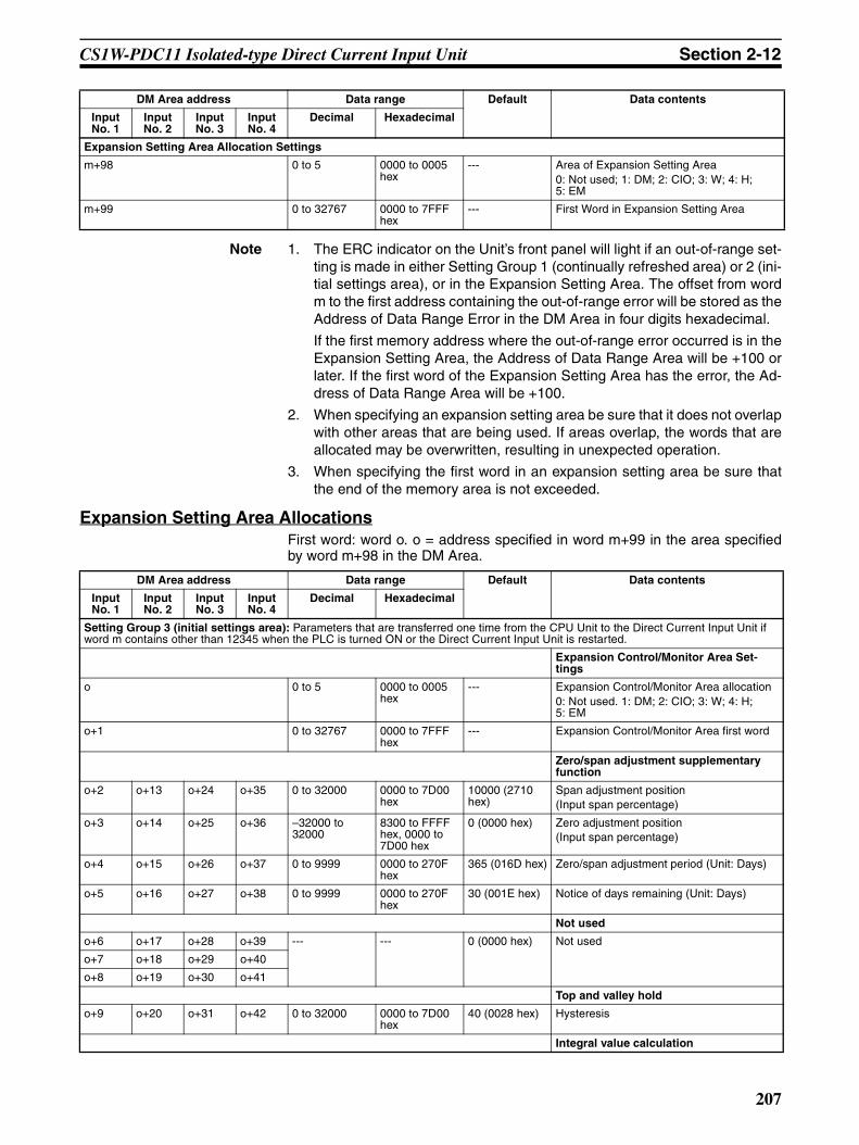
CS1W-PDC11 Isolated-type Direct Current Input Unit Section 2-12
Note 1. The ERC indicator on the Unit’s front panel will light if an out-of-range set-ting is made in either Setting Group 1 (continually refreshed area) or 2 (ini-tial settings area), or in the Expansion Setting Area. The offset from wordm to the first address containing the out-of-range error will be stored as theAddress of Data Range Error in the DM Area in four digits hexadecimal.
If the first memory address where the out-of-range error occurred is in theExpansion Setting Area, the Address of Data Range Area will be +100 orlater. If the first word of the Expansion Setting Area has the error, the Ad-dress of Data Range Area will be +100.
2. When specifying an expansion setting area be sure that it does not overlapwith other areas that are being used. If areas overlap, the words that areallocated may be overwritten, resulting in unexpected operation.
3. When specifying the first word in an expansion setting area be sure thatthe end of the memory area is not exceeded.
Expansion Setting Area AllocationsFirst word: word o. o = address specified in word m+99 in the area specifiedby word m+98 in the DM Area.
Expansion Setting Area Allocation Settings
m+98 0 to 5 0000 to 0005 hex
--- Area of Expansion Setting Area0: Not used; 1: DM; 2: CIO; 3: W; 4: H; 5: EM
m+99 0 to 32767 0000 to 7FFF hex
--- First Word in Expansion Setting Area
DM Area address Data range Default Data contents
Input No. 1
Input No. 2
Input No. 3
Input No. 4
Decimal Hexadecimal
DM Area address Data range Default Data contents
Input No. 1
Input No. 2
Input No. 3
Input No. 4
Decimal Hexadecimal
Setting Group 3 (initial settings area): Parameters that are transferred one time from the CPU Unit to the Direct Current Input Unit if word m contains other than 12345 when the PLC is turned ON or the Direct Current Input Unit is restarted.
Expansion Control/Monitor Area Set-tings
o 0 to 5 0000 to 0005 hex
--- Expansion Control/Monitor Area allocation0: Not used. 1: DM; 2: CIO; 3: W; 4: H; 5: EM
o+1 0 to 32767 0000 to 7FFF hex
--- Expansion Control/Monitor Area first word
Zero/span adjustment supplementary function
o+2 o+13 o+24 o+35 0 to 32000 0000 to 7D00 hex
10000 (2710 hex)
Span adjustment position(Input span percentage)
o+3 o+14 o+25 o+36 –32000 to 32000
8300 to FFFF hex, 0000 to 7D00 hex
0 (0000 hex) Zero adjustment position(Input span percentage)
o+4 o+15 o+26 o+37 0 to 9999 0000 to 270F hex
365 (016D hex) Zero/span adjustment period (Unit: Days)
o+5 o+16 o+27 o+38 0 to 9999 0000 to 270F hex
30 (001E hex) Notice of days remaining (Unit: Days)
Not used
o+6 o+17 o+28 o+39 --- --- 0 (0000 hex) Not used
o+7 o+18 o+29 o+40
o+8 o+19 o+30 o+41
Top and valley hold
o+9 o+20 o+31 o+42 0 to 32000 0000 to 7D00 hex
40 (0028 hex) Hysteresis
Integral value calculation
207

CS1W-PDC11 Isolated-type Direct Current Input Unit Section 2-12
Note 1. When specifying an expansion control/monitor area be sure that it does notoverlap with other areas that are being used. If areas overlap, the wordsthat are allocated may be overwritten, resulting in unexpected operation.
2. When specifying the first word in an expansion control/monitor area besure that the end of the memory area is not exceeded.
o+10 o+21 o+32 o+43 0, 1 0000, 0001 hex 0 (0000 hex) Integer unit0: Minutes; 1: Hours
Not used
o+11 o+22 o+33 o+44 --- --- 0 (0000 hex) Not used.
o+12 o+23 o+34 o+45
DM Area address Data range Default Data contents
Input No. 1
Input No. 2
Input No. 3
Input No. 4
Decimal Hexadecimal
208

CS1W-PDC11 Isolated-type Direct Current Input Unit Section 2-12
CIO Area AllocationsFirst word: word n. n = 2000 + unit number × 10 (unit number: 0 to 95)
Direction Word Bit Name Data range Contents
Direct Current Input Unit to CPU Unit
n 00 Input No. 1 Process value LL (low low limit) alarm
0, 1 0: Process value > Set value1: Process value ≤ Set value01 Process value L
(low limit) alarm0, 1
02 Process value H (high limit) alarm
0, 1 0: Process value < Set value1: Process value ≥ Set value03 Process value
HH (high high limit) alarm
0, 1
04 Input No. 2 Process value LL (low low limit) alarm
0, 1 Same as for input No. 1.
05 Process value L (low limit) alarm
0, 1
06 Process value H (high limit) alarm
0, 1
07 Process value HH (high high limit) alarm
0, 1
08 Input No. 3 Process value LL (low low limit) alarm
0, 1
09 Process value L (low limit) alarm
0, 1
10 Process value H (high limit) alarm
0, 1
11 Process value HH (high high limit) alarm
0, 1
12 Input No. 4 Process value LL (low low limit) alarm
0, 1
13 Process value L (low limit) alarm
0, 1
14 Process value H (high limit) alarm
0, 1
15 Process value HH (high high limit) alarm
0, 1
209

CS1W-PDC11 Isolated-type Direct Current Input Unit Section 2-12
Direct Current Input Unit to CPU Unit, con-tinued
n+1 0 to 15 Input No. 1 process value –32768 to 32767 (8000 to FFFF hex, 0000 to 7FFF hex)
The present process value is stored according to the scaling set in the allocated words of the DM Area.n+2 0 to 15 Input No. 2 process value –32768 to 32767
(8000 to FFFF hex, 0000 to 7FFF hex)
n+3 0 to 15 Input No. 3 process value –32768 to 32767 (8000 to FFFF hex, 0000 to 7FFF hex)
n+4 0 to 15 Input No. 4 process value –32768 to 32767 (8000 to FFFF hex, 0000 to 7FFF hex)
n+5 0 to 15 Input No. 1 rate-of-change value
–32768 to 32767 (8000 to FFFF hex, 0000 to 7FFF hex)
The present rate-of-change value is stored according to the scaling set in the allo-cated words of the DM Area.
n+6 0 to 15 Input No. 2 rate-of-change value
–32768 to 32767 (8000 to FFFF hex, 0000 to 7FFF hex)
n+7 0 to 15 Input No. 3 rate-of-change value
–32768 to 32767 (8000 to FFFF hex, 0000 to 7FFF hex)
n+8 0 to 15 Input No. 4 rate-of-change value
–32768 to 32767 (8000 to FFFF hex, 0000 to 7FFF hex)
Direction Word Bit Name Data range Contents
210

CS1W-PDC11 Isolated-type Direct Current Input Unit Section 2-12
Direct Current Input Unit to CPU Unit, con-tinued
n+9 00 Input No. 1 Rate-of-change value L (low limit) alarm
0, 1 0: Rate-of-change value > set value
1: Rate-of-change value ≤ set value
01 Rate-of-change value H (high limit) alarm
0, 1 0: Rate-of-change value < set value1: Rate-of-change value ≥ set value
02 Input No. 2 Rate-of-change value L (low limit) alarm
0, 1 Same as for input No. 1.
03 Rate-of-change value H (high limit) alarm
0, 1
04 Input No. 3 Rate-of-change value L (low limit) alarm
0, 1
05 Rate-of-change value H (high limit) alarm
0, 1
06 Input No. 4 Rate-of-change value L (low limit) alarm
0, 1
07 Rate-of-change value H (high limit) alarm
0, 1
08 Input No. 1 input error 0, 1 0: Normal1: Error (less than –17.2% or greater than 112.5%)Note Checks are con-
ducted for inputs of 4 to 20 mA and 1 to 5 V.
09 Input No. 2 input error 0, 1
10 Input No. 3 input error 0, 1
11 Input No. 4 input error 0, 1
12 Not used. 0, 1 Not used.
13 Zero/span adjustment period end
0, 1 0: Adjustment enabled1: Adjustment ended
14 Zero/span adjustment period notice
0, 1 0: Adjustment enabled1: Notice period
15 Not used. 0 Not used.
Direction Word Bit Name Data range Contents
211
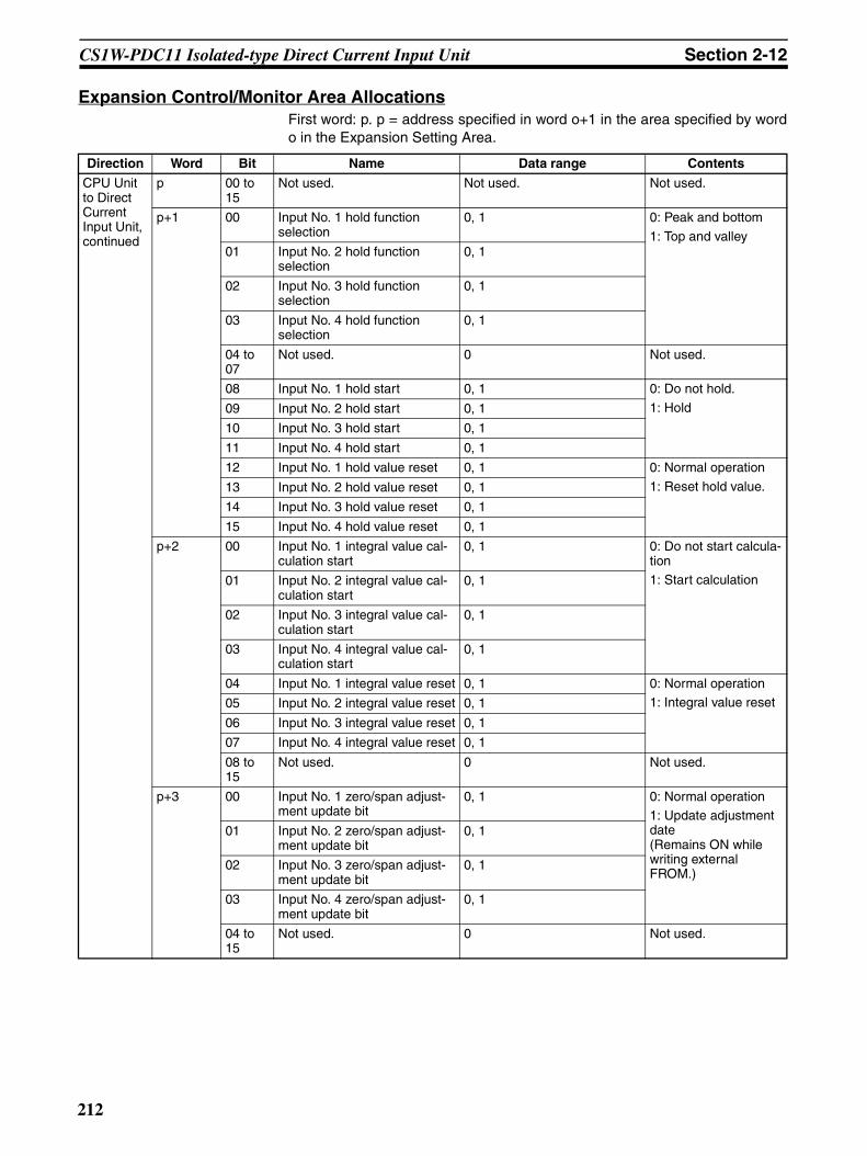
CS1W-PDC11 Isolated-type Direct Current Input Unit Section 2-12
Expansion Control/Monitor Area AllocationsFirst word: p. p = address specified in word o+1 in the area specified by wordo in the Expansion Setting Area.
Direction Word Bit Name Data range Contents
CPU Unit to Direct Current Input Unit, continued
p 00 to 15
Not used. Not used. Not used.
p+1 00 Input No. 1 hold function selection
0, 1 0: Peak and bottom
1: Top and valley01 Input No. 2 hold function
selection0, 1
02 Input No. 3 hold function selection
0, 1
03 Input No. 4 hold function selection
0, 1
04 to 07
Not used. 0 Not used.
08 Input No. 1 hold start 0, 1 0: Do not hold.
1: Hold09 Input No. 2 hold start 0, 1
10 Input No. 3 hold start 0, 1
11 Input No. 4 hold start 0, 1
12 Input No. 1 hold value reset 0, 1 0: Normal operation
1: Reset hold value.13 Input No. 2 hold value reset 0, 1
14 Input No. 3 hold value reset 0, 1
15 Input No. 4 hold value reset 0, 1
p+2 00 Input No. 1 integral value cal-culation start
0, 1 0: Do not start calcula-tion1: Start calculation01 Input No. 2 integral value cal-
culation start0, 1
02 Input No. 3 integral value cal-culation start
0, 1
03 Input No. 4 integral value cal-culation start
0, 1
04 Input No. 1 integral value reset 0, 1 0: Normal operation1: Integral value reset05 Input No. 2 integral value reset 0, 1
06 Input No. 3 integral value reset 0, 1
07 Input No. 4 integral value reset 0, 1
08 to 15
Not used. 0 Not used.
p+3 00 Input No. 1 zero/span adjust-ment update bit
0, 1 0: Normal operation1: Update adjustment date(Remains ON while writing external FROM.)
01 Input No. 2 zero/span adjust-ment update bit
0, 1
02 Input No. 3 zero/span adjust-ment update bit
0, 1
03 Input No. 4 zero/span adjust-ment update bit
0, 1
04 to 15
Not used. 0 Not used.
212

CS1W-PDC11 Isolated-type Direct Current Input Unit Section 2-12
Direct Cur-rent Input Unit to CPU Unit
p+4 00 Input No. 1
Zero/span adjustment period end
0, 1 0: Adjustment enabled.
1: Adjustment period end
01 Zero/span adjustment period notice
0, 1 0: Adjustment enabled.1: Notice period in effect.Remains set to 1 if the zero/span adjustment bit has never been ON.
02 Input No. 2
Zero/span adjustment period end
0, 1
03 Zero/span adjustment period notice
0, 1
04 Input No. 3
Zero/span adjustment period end
0, 1
05 Zero/span adjustment period notice
0, 1
06 Input No. 4
Zero/span adjustment period end
0, 1
07 Zero/span adjustment period notice
0, 1
08 External FROM error 0, 1 0: Normal operation.
1: External FROM error.
09 to 15
Not used. 0 Not used.
p+5 00 to 15
Input No. 1
Day of final adjustment date
0100 to 3100 (BCD) Remains set to FFFF if the zero/span adjust-ment bit has never been ON.
p+6 00 to 15
Year and month of final adjustment date
0001 to 9912 (BCD)
p+7 00 to 15
Input No. 2
Day of final adjustment date
0100 to 3100 (BCD)
p+8 00 to 15
Year and month of final adjustment date
0001 to 9912 (BCD)
p+9 00 to 15
Input No. 3
Day of final adjustment date
0100 to 3100 (BCD)
p+10 00 to 15
Year and month of final adjustment date
0001 to 9912 (BCD)
p+11 00 to 15
Input No. 4
Day of final adjustment date
0100 to 3100 (BCD)
p+12 00 to 15
Year and month of final adjustment date
0001 to 9912 (BCD)
p+13 to p+16
00 to 15
Not used. 0000 Not used.
p+17 00 to 15
Input No. 1
Peak/top value −32728 to +32767(8000 to FFFF hex, 0000 to 7FFF hex)
Counts the number of repetitions of condi-tional operations set in the Expansion Setting Area.
p+18 00 to 15
Bottom/valley value −32728 to +32767(8000 to FFFF hex, 0000 to 7FFF hex)
The bottom or valley value is stored accord-ing to the scaling set in the DM Area.
Direction Word Bit Name Data range Contents
213

CS1W-PDC11 Isolated-type Direct Current Input Unit Section 2-12
Direct Cur-rent Input Unit to CPU Unit
p+19 00 to 15
Input No. 2
Peak/top value −32728 to +32767(8000 to FFFF hex, 0000 to 7FFF hex)
Same as for Input No. 1.
p+20 00 to 15
Bottom/valley value −32728 to +32767
(8000 to FFFF hex, 0000 to 7FFF hex)
p+21 00 to 15
Input No. 3
Peak/top value −32728 to +32767
(8000 to FFFF hex, 0000 to 7FFF hex)
p+22 00 to 15
Bottom/valley value −32728 to +32767(8000 to FFFF hex, 0000 to 7FFF hex)
p+23 00 to 15
Input No. 4
Peak/top value −32728 to +32767(8000 to FFFF hex, 0000 to 7FFF hex)
p+24 00 to 15
Bottom/valley value −32728 to +32767(8000 to FFFF hex, 0000 to 7FFF hex)
p+25 00 to 15
Input No. 1
Integral value (lower digit)
−2147483648 to 2147483647(80000000 to FFFFFFFF hex, 00000000 to 7FFFFFFF hex)
The integral value for the present value is stored according to the scaling set in the DM Area.
p+26 00 to 15
Integral value (upper digit)
p+27 00 to 15
Input No. 2
Integral value (lower digit)
−2147483648 to 2147483647(80000000 to FFFFFFFF hex, 00000000 to 7FFFFFFF hex)p+28 00 to
15Integral value (upper digit)
p+29 00 to 15
Input No. 3
Integral value (lower digit)
−2147483648 to 2147483647
(80000000 to FFFFFFFF hex, 00000000 to 7FFFFFFF hex)p+30 00 to
15Integral value (upper digit)
p+31 00 to 15
Input No. 4
Integral value (lower digit)
−2147483648 to 2147483647
(80000000 to FFFFFFFF hex, 00000000 to 7FFFFFFF hex)p+32 00 to
15Integral value (upper digit)
p+33 and p+34
00 to 15
Not used. 0000 Not used.
Direction Word Bit Name Data range Contents
214

CS1W-PDC11 Isolated-type Direct Current Input Unit Section 2-12
Terminal Connection Diagram
Note • In both of the above cases, leave all unused inputs open between thepositive and negative terminals (e.g., between B1 and B2 for voltage inputNo. 1).
• Always ground the GR terminal on the Power Supply Unit of the PLC.• If the input device uses a voltage generator, temperature compensator, or
similar device, then ground the input device if it has a ground terminal. • Always short-circuit the V and I terminals when using current input.• Be sure to tighten the short bars to a torque of 0.5 N·m. Loose short bars
may result in conversion errors.
V1
COM1
V2
COM2
V3
COM3
V4
COM4
N.C.
N.C.
B1
B2
B3
B4
B5
B6
B7
B8
B9
B10
A1
A2
A3
A4
A5
A6
A7
A8
A9
A10
A11
N.C.
I1
N.C.
I2
N.C.
I3
N.C.
I4
N.C.
N.C.
N.C.
CS1W-PDC11
Voltage Inputs
+
−
+
−
+
−
+
−
Voltage output device
Voltage output device
Voltage output device
Voltage output device
CS1W-PDC11
Current inputs
V1
COM1
V2
COM2
V3
COM3
V4
COM4
N.C.
N.C.
B1
B2
B3
B4
B5
B6
B7
B8
B9
B10
A1
A2
A3
A4
A5
A6
A7
A8
A9
A10
A11
N.C.
I1
N.C.
I2
N.C.
I3
N.C.
I4
N.C.
N.C.
N.C.
Current output device
Current output device
Current output device
Current output device
+
−
+
−
+
−
+
−
+
−
+
−
+
−
+
−
V1+
COM1
V2+
COM2
V3+
COM3
V4+
COM4
NC
NC
NC
I1+
NC
I2+
NC
I3+
NC
I4+
NC
NC
NC
PDC11 terminal block
Current output device
Current output device
Current output device
Current output device
Short bars
215

CS1W-PDC11 Isolated-type Direct Current Input Unit Section 2-12
Terminal Block Diagram
Error Processing
Conversion Data Does Not Change.Probable cause Remedy
The gain for span adjustment is set to 0.
Set the gain for span adjustment to a value other than 0.
The minimum and maximum val-ues for process value scaling are either the same or are set extremely low.
Set the minimum and maximum values correctly.
The input signal type or process value range is set incorrectly.
Check and reset the input signal type and the process value range settings.
An input device is malfunctioning, input wiring is faulty, or wiring is disconnected.
Check whether the input voltage or current has changed. Check for faulty or disconnected wir-ing.Check whether an input error has been detected in the I/O Area.
26 VDC
5 VDC
V2+
I2+
COM2
V1+
I1+
COM1
V4+
I4+
COM4
V3+
I3+
COM3
B3
A4
B4
B1
A2
B2
B7
A8
B8
B5
A6
B6
250 Ω
1 MΩ
1 MΩ
250 Ω
1 MΩ
1 MΩ
250 Ω
1 MΩ
1 MΩ
250 Ω
1 MΩ
1 MΩ
Isolation circuit
Photocoupler
Am
plifi
er
circ
uit A/D
converter
Con
nect
or
Input selector
Digital circuits
Isolation circuit
Photocoupler
Am
plifi
er
circ
uit A/D
converter
Am
plifi
er
circ
uit A/D
converter
Isolation circuit
Photocoupler
Am
plifi
er
circ
uit A/D
converter
Isolation circuit
Photocoupler
216

CS1W-PDC11 Isolated-type Direct Current Input Unit Section 2-12
Values are Not Converted as Intended.
Converted Values are Unstable.
Probable cause Remedy
The input signal type or process value scaling is set incorrectly.
Check and reset the input signal type and the process value scaling settings.
The zero/span adjustment data is incorrect.
Check and correct the zero/span adjustment set-tings.
The square root function is operat-ing.
Set the square function so that it does not oper-ate.
Probable cause Remedy
Input signals are being affected by external noise.
Change the connection paths of the input signal lines. (Separate them from sources of noise or use shielded cable.)
Insert 0.01-µF to 0.1-µF ceramic capacitors between the I+ and COM input terminals.
Increase the number of values for calculating the moving average in mean value processing.
The scaling value is greater than the Unit’s resolution.
Reduce the scaling value.
217
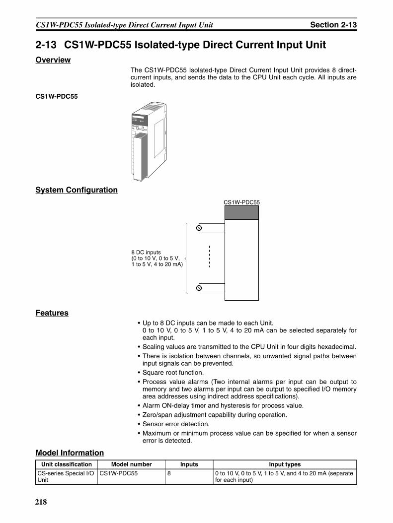
CS1W-PDC55 Isolated-type Direct Current Input Unit Section 2-13
2-13 CS1W-PDC55 Isolated-type Direct Current Input UnitOverview
The CS1W-PDC55 Isolated-type Direct Current Input Unit provides 8 direct-current inputs, and sends the data to the CPU Unit each cycle. All inputs areisolated.
CS1W-PDC55
System Configuration
Features• Up to 8 DC inputs can be made to each Unit.
0 to 10 V, 0 to 5 V, 1 to 5 V, 4 to 20 mA can be selected separately foreach input.
• Scaling values are transmitted to the CPU Unit in four digits hexadecimal.• There is isolation between channels, so unwanted signal paths between
input signals can be prevented.• Square root function.• Process value alarms (Two internal alarms per input can be output to
memory and two alarms per input can be output to specified I/O memoryarea addresses using indirect address specifications).
• Alarm ON-delay timer and hysteresis for process value.• Zero/span adjustment capability during operation.• Sensor error detection.• Maximum or minimum process value can be specified for when a sensor
error is detected.
Model Information
MACHNo.
X100
FEDCBA9876543210 FEDCBA9876543
210X101
RUNERC
ERH
CS1W-PDC55
8 DC inputs(0 to 10 V, 0 to 5 V, 1 to 5 V, 4 to 20 mA)
Unit classification Model number Inputs Input types
CS-series Special I/O Unit
CS1W-PDC55 8 0 to 10 V, 0 to 5 V, 1 to 5 V, and 4 to 20 mA (separate for each input)
218
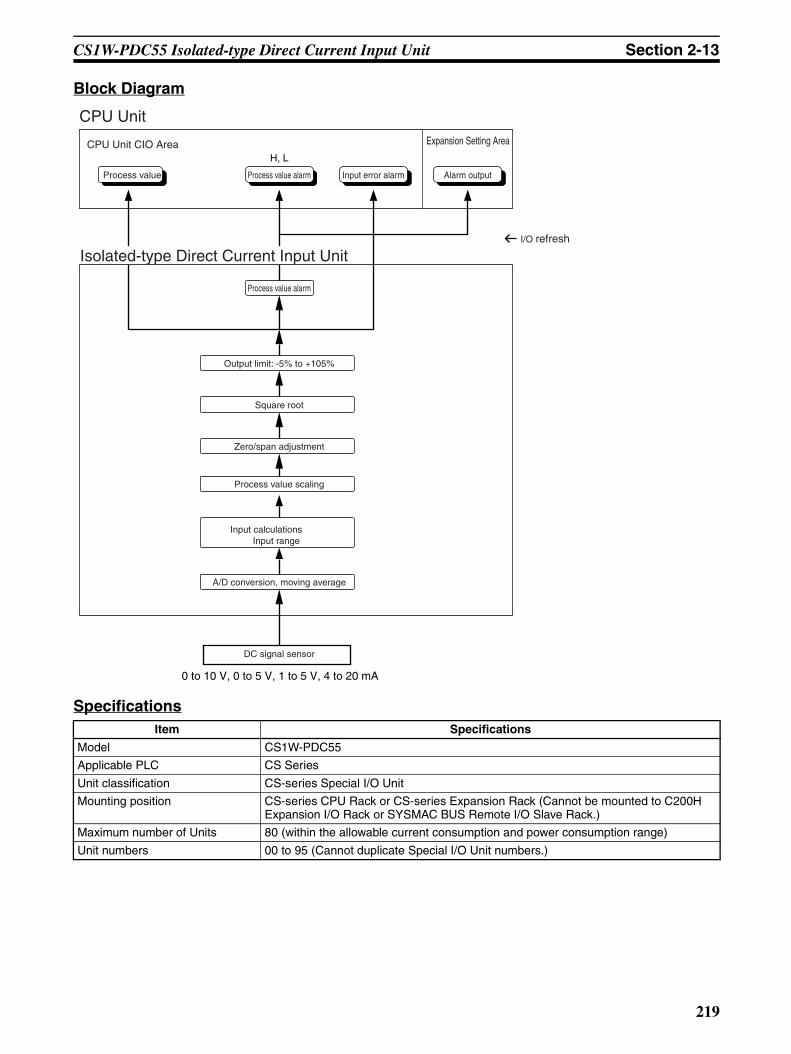
CS1W-PDC55 Isolated-type Direct Current Input Unit Section 2-13
Block Diagram
SpecificationsItem Specifications
Model CS1W-PDC55
Applicable PLC CS Series
Unit classification CS-series Special I/O Unit
Mounting position CS-series CPU Rack or CS-series Expansion Rack (Cannot be mounted to C200H Expansion I/O Rack or SYSMAC BUS Remote I/O Slave Rack.)
Maximum number of Units 80 (within the allowable current consumption and power consumption range)
Unit numbers 00 to 95 (Cannot duplicate Special I/O Unit numbers.)
H, L
0 to 10 V, 0 to 5 V, 1 to 5 V, 4 to 20 mA
Output limit: -5% to +105%
Square root
Zero/span adjustment
Process value scaling
Input calculationsInput range
A/D conversion, moving average
DC signal sensor
CPU UnitExpansion Setting Area
I/O refresh
Process value Process value alarm Alarm outputInput error alarm
CPU Unit CIO Area
Isolated-type Direct Current Input Unit
Process value alarm
219

CS1W-PDC55 Isolated-type Direct Current Input Unit Section 2-13
Areas for data exchange with CPU Unit
Special I/O Unit Area
10 words/UnitIsolated-type Direct Current Input Unit to CPU Unit:All process values, process value alarms (L, H), conversion data enabled flags, input errors
DM Area words allocated to Special I/O Units
100 words/UnitCPU Unit to Isolated-type Direct Current Input Unit:Input signal type (separate for each input), process value alarm setting (L, H), zero/span adjustment value, Square root function.
Expansion Con-trol/Monitor Area
1 word/Unit CPU Unit to Isolated-type Direct Current Input Unit:
Process value alarms
Number of inputs 8
Input signal type 0 to 10 V, 0 to 5 V, 1 to 5 V, 4 to 20 mA (separate for each input). (“Not used” can be selected).
Input signal type and scaling to industrial units are separate for each of the 8 inputs.Note Input signal type and scaling to
industrial units are set in the DM Area.
Example:Input signal type: 4 to 20 mA; industrial unit scaling: 0 to 500 m3/h (after square root extraction). DM Area settings are as follows:Input signal type: 3 (0003 hex)Industrial unit maximum value stored: 500 (01F4 hex)Industrial unit minimum value stored: 0 (0000 hex)
Scaling Data to be stored in the allocated words in the CIO area must be scaled (Any mini-mum and maximum values can be set.) (8 inputs set separately.) Data can be con-verted at 0% to 100%.
Data storage in the CIO Area The value derived from carrying out the following processing in order of the actual process data in the input range is stored in four digits hexadecimal (binary values) in the allocated words in the CIO Area.1) Scaling → 2) Zero/span adjustment → 3) Square root calculation → 4) Output limits
Accuracy (25°C) ±0.3% of full scale
Temperature Characteristics For voltage inputs: 100 ppm/°C of full scale.For current inputs: 120 ppm/°C of full scale.
Resolution 1/16,000 of full scale
Input signal range For all inputs:−5 to +105%
Maximum input rating Voltage: ±15 VCurrent: ±30 mA
Input impedance For current inputs: 250 Ω (typical)For voltage inputs: 1 MΩ min.
Warmup time 10 min
Conversion period 250 ms/8 inputs
Maximum time to store data in CPU Unit
Conversion period + one CPU Unit cycle
Input error detection Detects sensor error at each input and turns ON the Sensor error Flag.The process value overrange direction for when a sensor error occurs can be speci-fied. (High: 105% of input range; low: −5% of input range)
Item Specifications
220

CS1W-PDC55 Isolated-type Direct Current Input Unit Section 2-13
DM Area AllocationsFirst word: word m. m = D20000 + unit number × 100 (unit number: 0 to 95)
Function Process value alarm
Process value 8-point alarm (L H), hysteresis, and ON-delay timer (0 to 60 s) are available.
Two alarms per input (L, H) can be output to addresses in the CIO Area specified in the Expansion Setting Area.
Square root cal-culation(Supported only when input is 1 to 5 v or 4 to 20 mA.)
When the maximum value for process value scaling is A and the minimum value is B,
Drop-out: Output approx. 7% max. linear (output = input) characteristic
Note 1 The square root function can only be used when the maximum scaling value is greater than the minimum scaling value. The square root will not be found if the maximum is smaller than the minimum.
Note 2 When the square root function is used, set the scaling values after square root calculation (e.g., for flow rates or other values) for the process value scal-ing A and B settings.
Isolation Between inputs and between inputs and PLC signals: Isolation by transformer and photocoupler.
Insulation resistance 20 MΩ max. (at 500 V DC).Between all input terminals and external AC terminals (Power Supply Unit)Between all input terminals and FG plate
Dielectric strength Between all input terminals and external AC terminals (Power Supply Unit)Between all input terminals and FG plate1,000 VAC, 50/60 Hz 1 min., detection current: 1 mA
Between all channels500 VAC, 50/60 Hz 1 min., detection current: 1 mA
External connections Terminal block (detachable)
Unit number settings Set by rotary switches on front panel, from 0 to 95.
Indicators Three LED indicators on front panel (for normal operation, errors detected at the Direct Current Input Unit, and errors detected at the CPU Unit).
Front panel connector Sensor input connector terminal block (detachable)
Effect on CPU Unit cycle time 0.4 ms
Current consumption 5 V DC at 180 mA max., 26 V DC at 60 mA max.
Dimensions 35 × 130 × 126 mm (W × H × D)Note The height including the Backplane is 145 mm.
Weight 450 g max.
Item Specifications
(A − B) × (input − B) + BOutput =
DM Area address Data range Default Data contents
Input No. 1
Input No. 2
Input No. 3
Input No. 4
Input No. 5
Input No. 6
Input No. 7
Input No. 8
Decimal Hexadec-imal
m 12345, 0 3039, 0000 hex
0000 hex Default block read commandSpecifies the direction of data transfer when the PLC is turned ON or the Unit is restarted for DM Area words m+1 to m+97.• 12345 (3039 hex): The data in words
m+2 to m+98 is transferred from theDirect Current Input Unit to the CPUUnit. When the transfer is completed,the value will become 0000 hex.
• Other than 12345 (such as 0000 hex):The data in the allocated words of DMArea is transferred from the CPU Unit tothe Direct Current Input Unit.
Display parameter
m+1 0 to 83 0000 to 0053 hex
0 (0000 hex)
Address of Data Range Error (See note 1.)
221

CS1W-PDC55 Isolated-type Direct Current Input Unit Section 2-13
Setting Group 1 (continuously refreshed area): Parameters that are continuously refreshed during PLC operation (regardless of the CPU Unit’s operation mode)
Process value alarm settings
m+2 m+6 m+10 m+14 m+18 m+22 m+26 m+30 Low to high limit for sensors.
4200 (1068 hex)
Process value H (high limit) alarm setting
m+3 m+7 m+11 m+15 m+19 m+23 m+27 m+31 −200 (FF38 hex)
Process value L (low limit) alarm setting
Span adjustment value
m+4 m+8 m+12 m+16 m+20 m+24 m+28 m+32 0 to 32000
0000 to 7D00 hex
10000 (2710 hex)
Set value × 0.0001
Zero adjustment value
m+5 m+9 m+13 m+17 m+21 m+25 m+29 m+33 –9999 to 9999
D8F1 to 270F hex
0 (0000 hex)
Set value × 0.1
Setting Group 2 (initial settings area): Parameters that are transferred one time from the CPU Unit to the Direct Current Input Unit if word m contains other than 12345 when the PLC is turned ON or the Direct Current Input Unit is restarted.
Operation settings (See note 2.)
m +34 (See note 2.)
(See note 2.)
0(0000 hex)
04: Data display (binary or BCD)08: Minus sign display format for BCD dis-play12: Data direction at sensor error13: Data held at sensor error
Input signal type
m+35 m+41 m+47 m+53 m+59 m+65 m+71 m+77 0 to 3, 15
0000 to 0003,000F hex
0 (0000 hex)
0: 0 to 10 V; 1: 0 to 5 V; 2: 1 to 5 V; 3: 4 to 20 mA; F: Not used
Alarm hysteresis
m+36 m+42 m+48 m+54 m+60 m+66 m+72 m+78 0 to 9999
0000 to 270F hex
0 (0000 hex)
Set value × 0.1
Alarm ON-delay time
m+37 m+43 m+49 m+55 m+61 m+67 m+73 m+79 0 to 60 0000 to 003C hex
0 (0000 hex)
Unit: s
Square root function(Supported only when input is 1 to 5 V or 4 to 20 mA.)
m+38 m+44 m+50 m+56 m+62 m+68 m+74 m+80 0, 1 0000, 0001 hex
0 (0000 hex)
Square root extraction (when maximum scaling value > minimum scaling value)0: Disable; 1: Enable
Process value scaling
m+39 m+45 m+51 m+57 m+63 m+69 m+75 m+81 –32000 to 32000
8300 to FFFF hex, 0000 to 7D00 hex
4000 (0FA0 hex)
Value stored for maximum value in range (span)
m+40 m+46 m+52 m+58 m+64 m+70 m+76 m+82 –32000 to 32000
8300 to FFFF hex, 0000 to 7D00 hex
0 (0000 hex)
Value stored for minimum value in range (zero)
Expansion Setting Area enable
m+83 0, 1 0000, 0001 hex
0 (0000 hex)
0: Disabled1: Enabled
Expansion Setting Area address
m+84(See note 3.)
0 to 6143
0000 to 17FF hex
0 (0000 hex)
CIO area (fixed)Number of words.
DM Area address Data range Default Data contents
Input No. 1
Input No. 2
Input No. 3
Input No. 4
Input No. 5
Input No. 6
Input No. 7
Input No. 8
Decimal Hexadec-imal
222

CS1W-PDC55 Isolated-type Direct Current Input Unit Section 2-13
Note 1. The ERC indicator on the Unit's front panel will light if an out-of-range set-ting is made in either Setting Group 1 (continuously refreshed area) or 2(initial settings area). The offset from word m to the first word containingthe out-of-range error will be stored as the Address of Data Range Error inthe DM Area in four digits hexadecimal.
2. The operation settings are shown in the following table
3. A range check is not performed for the Expansion Setting Area address setin word m+84. Be sure to check this address before starting actual opera-tion.
Example: For a binary data format and a data direction at sensor error of“lower limit,” word m+18 contains 1000.
Word Bits Description Settings
m+34 04 Data format 0: Binary (Negative values are given as 2’s comple-ments).
1: BCD
08 Minus sign display format for BCD display 0: “F” used to indicate the minus sign.
1: Leftmost bit used to indicate the minus sign.The setting is disabled if bits 04 to 07 are set to 0.
12 Data direction at sensor error 0: Goes to upper limit at sensor error
1: Goes to lower limit at sensor error
13 Data held at sensor error 0: Follow the setting of Data direction at sensor error
1: If there is a sensor error when the upper limit is exceeded, hold the data at the upper limit. If there is a sensor error when the lower limit is exceeded, hold the data at the lower limit.
223

CS1W-PDC55 Isolated-type Direct Current Input Unit Section 2-13
Expansion Setting AreaFirst word: word o. (o = address specified in word m+60 in the DM Area)
Note If either of the following changes is made for the Expansion Setting Area forthe CS1W-PTS55/PTS56/PDC55, the previous data will be left in the Expan-sion Setting Area even after the change has been made.Clear the previous data when changing either of these settings.
• The Expansion Setting Area Enable setting is changed from “enabled” to“disabled.”
• The Expansion Setting Area Address setting is changed while the Expan-sion Setting Area Enable setting is set to “enabled.”
Direction Word Bit Name Data range Contents
Direct Current Input Unit to CPU Unit
o 00 Input No. 1 Process value L (low limit) alarm
0, 1 0: Process value > Set value1: Process value ≤ Set value
01 Process value H (high limit) alarm
0, 1 0: Process value < Set value1: Process value ≥ Set value
02 Input No. 2 Process value L (low limit) alarm
0, 1 Same as for input No. 1.
03 Process value H (high limit) alarm
0, 1
04 Input No. 3 Process value L (low limit) alarm
0, 1
05 Process value H (high limit) alarm
0, 1
06 Input No. 4 Process value L (low limit) alarm
0, 1
07 Process value H (high limit) alarm
0, 1
08 Input No. 5 Process value L (low limit) alarm
0, 1
09 Process value H (high limit) alarm
0, 1
10 Input No. 6 Process value L (low limit) alarm
0, 1
11 Process value H (high limit) alarm
0, 1
12 Input No. 7 Process value L (low limit) alarm
0, 1
13 Process value H (high limit) alarm
0, 1
14 Input No. 8 Process value L (low limit) alarm
0, 1
15 Process value H (high limit) alarm
0, 1
224

CS1W-PDC55 Isolated-type Direct Current Input Unit Section 2-13
CIO Area AllocationsFirst word: n = 2000 + unit number × 10 (unit number: 0 to 95)
Direction Word Bit Name Data range Contents
Direct Current Input Unit to CPU Unit
n 00 Input No. 1 Process value L (low limit) alarm
0, 1 0: Process value > Set value1: Process value ≤ Set value
01 Process value H (high limit) alarm
0, 1 0: Process value < Set value1: Process value ≥ Set value
02 Input No. 2 Process value L (low limit) alarm
0, 1 Same as for input No. 1.
03 Process value H (high limit) alarm
0, 1
04 Input No. 3 Process value L (low limit) alarm
0, 1
05 Process value H (high limit) alarm
0, 1
06 Input No. 4 Process value L (low limit) alarm
0, 1
07 Process value H (high limit) alarm
0, 1
08 Input No. 5 Process value L (low limit) alarm
0, 1
09 Process value H (high limit) alarm
0, 1
10 Input No. 6 Process value L (low limit) alarm
0, 1
11 Process value H (high limit) alarm
0, 1
12 Input No. 7 Process value L (low limit) alarm
0, 1
13 Process value H (high limit) alarm
0, 1
14 Input No. 8 Process value L (low limit) alarm
0, 1
15 Process value H (high limit) alarm
0, 1
n + 1 00 to 15 Input No. 1 Process value Depends on type of input.
The integral value for the present value is stored according to the scaling set in the DM Area.
n + 2 00 to 15 Input No. 2
n + 3 00 to 15 Input No. 3
n + 4 00 to 15 Input No. 4
n + 5 00 to 15 Input No. 5
n + 6 00 to 15 Input No. 6
n + 7 00 to 15 Input No. 7
n + 8 00 to 15 Input No. 8
225
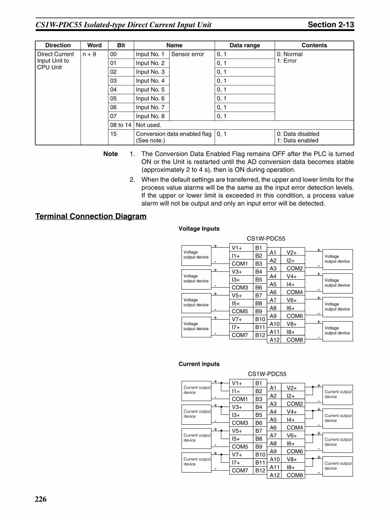
CS1W-PDC55 Isolated-type Direct Current Input Unit Section 2-13
Note 1. The Conversion Data Enabled Flag remains OFF after the PLC is turnedON or the Unit is restarted until the AD conversion data becomes stable(approximately 2 to 4 s), then is ON during operation.
2. When the default settings are transferred, the upper and lower limits for theprocess value alarms will be the same as the input error detection levels.If the upper or lower limit is exceeded in this condition, a process valuealarm will not be output and only an input error will be detected.
Terminal Connection Diagram
Direct Current Input Unit to CPU Unit
n + 9 00 Input No. 1 Sensor error 0, 1 0: Normal1: Error01 Input No. 2 0, 1
02 Input No. 3 0, 1
03 Input No. 4 0, 1
04 Input No. 5 0, 1
05 Input No. 6 0, 1
06 Input No. 7 0, 1
07 Input No. 8 0, 1
08 to 14 Not used.
15 Conversion data enabled flag (See note.)
0, 1 0: Data disabled1: Data enabled
Direction Word Bit Name Data range Contents
V1+I1+COM1V3+I3+COM3V5+I5+COM5V7+I7+COM7
B1B2B3B4B5B6B7B8B9B10B11B12
A1A2A3A4A5A6A7A8A9A10A11A12
V2+I2+COM2V4+I4+COM4V6+I6+COM6V8+I8+COM8
+Voltage output device
-+
Voltage output device
-+
Voltage output device
-+
Voltage output device
-
+Voltage output device
-+
Voltage output device
-+
Voltage output device
-+
Voltage output device
-
V1+I1+COM1V3+I3+COM3V5+I5+COM5V7+I7+COM7
B1B2B3B4B5B6B7B8B9B10B11B12
A1A2A3A4A5A6A7A8A9A10A11A12
V2+I2+COM2V4+I4+COM4V6+I6+COM6V8+I8+COM8
CS1W-PDC55+
Current output device
-+
Current output device
-+
Current output device
-+
Current output device
-
+Current output device
-+
Current output device
-+
Current output device
-+
Current output device
-
CS1W-PDC55
Voltage Inputs
Current inputs
226

CS1W-PDC55 Isolated-type Direct Current Input Unit Section 2-13
Con
nect
or
Note • In both of the above cases, leave all unused inputs open between thepositive and negative terminals.
• Always short-circuit the V and I terminals when using current input.
• Be sure to tighten the short bars to a torque of 0.5 N·m. Loose short barsmay result in conversion errors.
• Always ground the GR terminal on the Power Supply Unit of the PLC.• If the input device uses a voltage generator, temperature compensator, or
similar device, then ground the input device if it has a ground terminal.
Terminal Block Diagram
5 V DC
Isol
atio
n ci
rcui
t
Digital circuits
Amplifier circuit
Photocoupler
B1
B3
B2Double integral A/D
Reference power supply
Amplifier circuit
Photocoupler
A10
A12
A11Double integral A/D
Reference power supply
Amplifier circuit
Photocoupler
B7
B9
B8Double integral A/D
Reference power supply
Amplifier circuit
Photocoupler
Double integral A/D
Reference power supply
A5
A7
A6
Isol
atio
n ci
rcui
t
No. 2 inputPhotocoupler
No. 3 inputPhotocoupler
No. 6 inputPhotocoupler
No. 7 inputPhotocoupler
No. 2 inputReference power supply
No. 3 inputReference power supply
No. 6 inputReference power supply
No. 7 inputReference power supply
24 V DC
No.1 input
No.4 input
No.5 input
No.8 input
227

CS1W-PDC55 Isolated-type Direct Current Input Unit Section 2-13
Error Processing
Conversion Data Does Not Change.
Values are Not Converted as Intended.
Converted Values are Unstable.
Probable cause Remedy
The gain for span adjustment is set to 0.
Set the gain for span adjustment to a value other than 0.
The minimum and maximum val-ues for process value scaling are either the same or are set extremely low.
Set the minimum and maximum values correctly.
The input signal type or process value range is set incorrectly.
Check and reset the input signal type and the process value range settings.
An input device is malfunctioning, input wiring is faulty, or wiring is disconnected.
Check whether the input voltage or current has changed. Check for faulty or disconnected wir-ing.Check whether an input error has been detected in the I/O Area.
Probable cause Remedy
The input signal type or process value scaling is set incorrectly.
Check and reset the input signal type and the process value scaling settings.
The zero/span adjustment data is incorrect.
Check and correct the zero/span adjustment set-tings.
The square root function is operat-ing.
Set the square function so that it does not oper-ate.
Probable cause Remedy
Input signals are being affected by external noise.
Change the connection paths of the input signal lines. (Separate them from sources of noise or use shielded cable.)
Insert 0.01-µF to 0.1-µF ceramic capacitors between the I+ and COM input terminals.
Increase the number of values for calculating the moving average in mean value processing.
The scaling value is greater than the Unit’s resolution.
Reduce the scaling value.
228

CS1W-PTR01 Power Transducer Input Unit Section 2-14
2-14 CS1W-PTR01 Power Transducer Input UnitOverview
The CS1W-PTR01 Power Transducer Input Unit provides up to eight inputs of0 to 1 mA or –1 to 1 mA from power transducers, and sends the data to theCPU Unit each cycle.
System Configuration
Features• Up to eight inputs of 0 to 1 mA or –1 to 1 mA from a power transducer can
be separately connected.• Scaling values are sent to the CPU Unit in four digits hexadecimal.• The inrush input limit function temporarily limits the process value input to
a given set value when it increases from a low value (2%), in order to pre-vent process values from being jumped up by an inrush current when themotor is started up, and so on. (This function is available for inputs of 0 to1 mA only.)
• Two values for each process value alarm input.• ON-delay timer for process value alarm.• Mean value processing (for four values).• Zero/span adjustment capability during operation.
Model Information
CS1W-PTR01
Eight power transducer inputs (0 to 1 mA or −1 to 1 mA)
CS1W-PTR01
Unit classification Model number Inputs Input types
CS-series Special I/O Unit CS1W-PTR01 8 Either of the following can be selected separately: 0 to 1 mA, or –1 to 1 mA.
229

CS1W-PTR01 Power Transducer Input Unit Section 2-14
Block Diagram (Order of Processing)The processing for the eight inputs is as shown in the following diagram.
SpecificationsItem Specifications
Model CS1W-PTR01
Applicable PLC CS Series
Unit classification CS-series Special I/O Unit
Mounting position CS-series CPU Rack or CS-series Expansion Rack (Cannot be mounted to C200H Expansion I/O Rack or SYSMAC BUS Remote I/O Slave Rack.)
Maximum number of Units 80 (within the allowable current consumption and power consumption range)
Unit numbers 00 to 95 (Cannot duplicate Special I/O Unit numbers.)
CPU Unit CIO Area
Process value Process value alarm
Power Transducer Input Unit
Process value alarm
Output limit: −15% to +115%
Inrush input limit
Zero/span adjustment
Process value scaling
Input calculationsInput range
A/D conversion, moving average (for four values)
Power transducer
0 to 1 mA, −1 to 1 mA
I/O refresh
Type: current, voltage, effective power, reactive power, power rate, phase, frequency
Can be used when input range is 0 to 1 mA.
H, L
230

CS1W-PTR01 Power Transducer Input Unit Section 2-14
Areas for data exchange with CPU Unit
Special I/O Unit Area
10 words/UnitPower Transducer Input Unit to CPU Unit:All process values, process value alarms (L, H)
DM Area words allocated to Special I/O Units
100 words/Unit
CPU Unit to Power Transducer Input Unit:Input signal type, scaling of process value in industrial units, process value alarm set-ting (L, H), inrush input upper limit, inrush input upper limit time, zero/span adjustment value, etc.
Number of inputs 8
Input signal type Either 0 to 1 mA or –1 to 1 mA. Input signal type and scaling to industrial units are separate for each of the 8 inputs.Note Input signal type and scaling to
industrial units are set in the DM Area.
Example:Input signal type: 0 to 1 mA from power transducer; industrial unit scaling: 0 to 500 W. DM Area settings are as follows:
Input signal type: 0 (0000 hex)Industrial unit maximum value stored: 500 (01F4 hex)Industrial unit minimum value stored: 0 (0000 hex)
User-defined scaling in industrial units
Scaling required for the above input sig-nals. (Any minimum and maximum values can be set.) (8 inputs set separately.)
Data storage in the CIO Area The value derived from carrying out the following processing in order of the pro-cess value data is stored in four digits hexadecimal (binary values) in the allo-cated words in the CIO Area.1) Mean value processing → 2) Scaling → 3) Zero/span adjustment → 4) Inrush input limit → 5) Output limits
Accuracy (25°C) ±0.2% of full scale
Temperature coefficient ±0.015%/°C of full scale
Resolution 1/4,096 of full scale
Input signal range For 0 to 1 mA: –15 to 115%; for –1 to 1 mA: –7.5 to 107.5%
Input impedance 100 Ω (typical)
Warmup time 10 min
Response time 1.2 s (travel time from input 0% to 90%, for step input)
Conversion period 200 ms/8 inputs
Maximum time to store data in CPU Unit
Conversion period + one CPU Unit cycle
Input error detection None.
Operation at input disconnection Process value corresponding to 0 mA stored.
Function Inrush input limit
When the process value is increased from 2% or less, the inrush input limit function limits the increase for a set time. (It is available only for inputs of 0 to 1 mA.) This func-tion can be used to prevent sudden process value increases due to inrush currents caused by motor startup and so on.
Upper limit value: –32,000 to 32,000Upper limit time: 0 to 100 s
Process value alarm
Process value 2-point alarm (H, L), hysteresis, and ON-delay timer (0 to 60 s) are available.
Mean value processing (input filter)
Calculates the moving average for the past four process values (every 200 ms), and stores that value in the CIO Area as the process value.
Isolation Between inputs: No isolationBetween input terminals and PLC signals: Isolation by transformer and photocoupler
Insulation resistance 20 MΩ (at 500 V DC) between inputs and internal PLC signals
Dielectric strength Between inputs and internal PLC signals: 1,000 V AC, at 50/60 Hz, for 1 min, leakage current 10 mA max.
External connections Terminal block (detachable)
Unit number settings Set by rotary switches on front panel, from 0 to 95.
Indicators Three LED indicators on front panel (for normal operation, errors detected at the Power Transducer Input Unit, and errors related to the CPU Unit).
Item Specifications
231
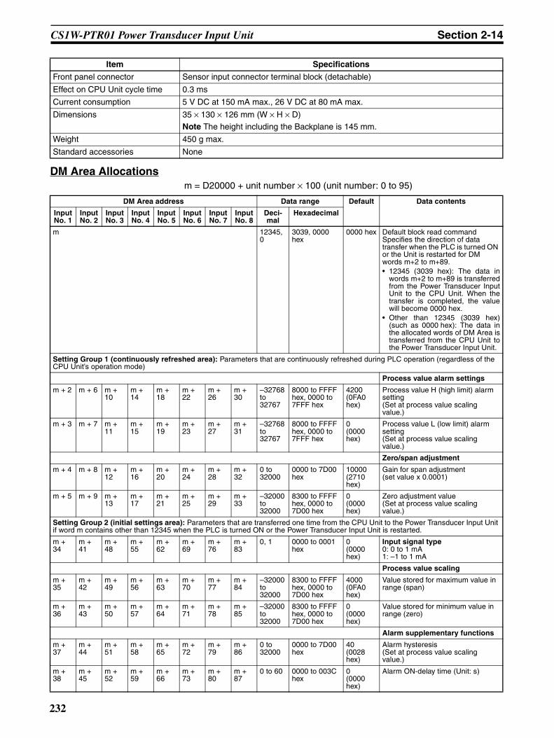
CS1W-PTR01 Power Transducer Input Unit Section 2-14
DM Area Allocationsm = D20000 + unit number × 100 (unit number: 0 to 95)
Front panel connector Sensor input connector terminal block (detachable)
Effect on CPU Unit cycle time 0.3 ms
Current consumption 5 V DC at 150 mA max., 26 V DC at 80 mA max.
Dimensions 35 × 130 × 126 mm (W × H × D)Note The height including the Backplane is 145 mm.
Weight 450 g max.
Standard accessories None
Item Specifications
DM Area address Data range Default Data contents
Input No. 1
Input No. 2
Input No. 3
Input No. 4
Input No. 5
Input No. 6
Input No. 7
Input No. 8
Deci-mal
Hexadecimal
m 12345, 0
3039, 0000 hex
0000 hex Default block read commandSpecifies the direction of data transfer when the PLC is turned ON or the Unit is restarted for DM words m+2 to m+89.• 12345 (3039 hex): The data in
words m+2 to m+89 is transferredfrom the Power Transducer InputUnit to the CPU Unit. When thetransfer is completed, the valuewill become 0000 hex.
• Other than 12345 (3039 hex)(such as 0000 hex): The data inthe allocated words of DM Area istransferred from the CPU Unit tothe Power Transducer Input Unit.
Setting Group 1 (continuously refreshed area): Parameters that are continuously refreshed during PLC operation (regardless of the CPU Unit’s operation mode)
Process value alarm settings
m + 2 m + 6 m + 10
m + 14
m + 18
m + 22
m + 26
m + 30
–32768 to 32767
8000 to FFFF hex, 0000 to 7FFF hex
4200 (0FA0 hex)
Process value H (high limit) alarm setting(Set at process value scaling value.)
m + 3 m + 7 m + 11
m + 15
m + 19
m + 23
m + 27
m + 31
–32768 to 32767
8000 to FFFF hex, 0000 to 7FFF hex
0 (0000 hex)
Process value L (low limit) alarm setting(Set at process value scaling value.)
Zero/span adjustment
m + 4 m + 8 m + 12
m + 16
m + 20
m + 24
m + 28
m + 32
0 to 32000
0000 to 7D00 hex
10000 (2710 hex)
Gain for span adjustment(set value x 0.0001)
m + 5 m + 9 m + 13
m + 17
m + 21
m + 25
m + 29
m + 33
–32000 to 32000
8300 to FFFF hex, 0000 to 7D00 hex
0 (0000 hex)
Zero adjustment value(Set at process value scaling value.)
Setting Group 2 (initial settings area): Parameters that are transferred one time from the CPU Unit to the Power Transducer Input Unit if word m contains other than 12345 when the PLC is turned ON or the Power Transducer Input Unit is restarted.
m + 34
m + 41
m + 48
m + 55
m + 62
m + 69
m + 76
m + 83
0, 1 0000 to 0001 hex
0 (0000 hex)
Input signal type0: 0 to 1 mA1: –1 to 1 mA
Process value scaling
m + 35
m + 42
m + 49
m + 56
m + 63
m + 70
m + 77
m + 84
–32000 to 32000
8300 to FFFF hex, 0000 to 7D00 hex
4000 (0FA0 hex)
Value stored for maximum value in range (span)
m + 36
m + 43
m + 50
m + 57
m + 64
m + 71
m + 78
m + 85
–32000 to 32000
8300 to FFFF hex, 0000 to 7D00 hex
0 (0000 hex)
Value stored for minimum value in range (zero)
Alarm supplementary functions
m + 37
m + 44
m + 51
m + 58
m + 65
m + 72
m + 79
m + 86
0 to 32000
0000 to 7D00 hex
40 (0028 hex)
Alarm hysteresis(Set at process value scaling value.)
m + 38
m + 45
m + 52
m + 59
m + 66
m + 73
m + 80
m + 87
0 to 60 0000 to 003C hex
0 (0000 hex)
Alarm ON-delay time (Unit: s)
232
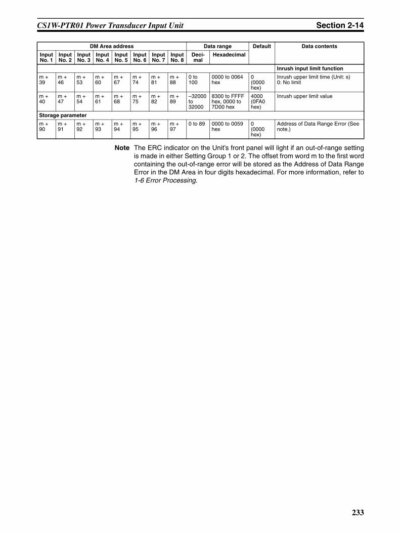
CS1W-PTR01 Power Transducer Input Unit Section 2-14
Note The ERC indicator on the Unit’s front panel will light if an out-of-range settingis made in either Setting Group 1 or 2. The offset from word m to the first wordcontaining the out-of-range error will be stored as the Address of Data RangeError in the DM Area in four digits hexadecimal. For more information, refer to1-6 Error Processing.
Inrush input limit function
m + 39
m + 46
m + 53
m + 60
m + 67
m + 74
m + 81
m + 88
0 to 100
0000 to 0064 hex
0 (0000 hex)
Inrush upper limit time (Unit: s)0: No limit
m + 40
m + 47
m + 54
m + 61
m + 68
m + 75
m + 82
m + 89
–32000 to 32000
8300 to FFFF hex, 0000 to 7D00 hex
4000 (0FA0 hex)
Inrush upper limit value
Storage parameter
m + 90
m + 91
m + 92
m + 93
m + 94
m + 95
m + 96
m + 97
0 to 89 0000 to 0059 hex
0 (0000 hex)
Address of Data Range Error (See note.)
DM Area address Data range Default Data contents
Input No. 1
Input No. 2
Input No. 3
Input No. 4
Input No. 5
Input No. 6
Input No. 7
Input No. 8
Deci-mal
Hexadecimal
233

CS1W-PTR01 Power Transducer Input Unit Section 2-14
CIO Area Allocationsn = 2000 + unit number × 10 (unit number: 0 to 95)
Direction Word Bit Name Data range Contents
Power Transducer Input Unit to CPU Unit
n 00 Input No. 1 Process value L (low limit) alarm
0, 1 0: Process value > Set value
1: Process value ≤ Set value
01 Process value H (high limit) alarm
0, 1 0: Process value < Set value1: Process value ≥ Set value
02 Input No. 2 Process value L (low limit) alarm
0, 1 Same as for input No. 1.
03 Process value H (high limit) alarm
0, 1
04 Input No. 3 Process value L (low limit) alarm
0, 1 Same as for input No. 1.
05 Process value H (high limit) alarm
0, 1
06 Input No. 4 Process value L (low limit) alarm
0, 1 Same as for input No. 1.
07 Process value H (high limit) alarm
0, 1
08 Input No. 5 Process value L (low limit) alarm
0, 1 Same as for input No. 1.
09 Process value H (high limit) alarm
0, 1
10 Input No. 6 Process value L (low limit) alarm
0, 1 Same as for input No. 1.
11 Process value H (high limit) alarm
0, 1
12 Input No. 7 Process value L (low limit) alarm
0, 1 Same as for input No. 1.
13 Process value H (high limit) alarm
0, 1
14 Input No. 8 Process value L (low limit) alarm
0, 1 Same as for input No. 1.
15 Process value H (high limit) alarm
0, 1
234

CS1W-PTR01 Power Transducer Input Unit Section 2-14
Terminal Connection Diagram
Note Leave all unused inputs open between the positive and negative terminals(e.g., between A1, and A2 for input No. 1). (They can, however, be short-cir-cuited with the lead wire.)
Power Transducer Input Unit to CPU Unit
n + 1 00 to 15 Input No. 1 process value –32768 to 32767 (8000 to FFFF hex, 0000 to 7FFF hex)
The present process value is stored according to the scal-ing set in the allocated words of the DM Area.
n + 2 00 to 15 Input No. 2 process value –32768 to 32767 (8000 to FFFF hex, 0000 to 7FFF hex)
n + 3 00 to 15 Input No. 3 process value –32768 to 32767 (8000 to FFFF hex, 0000 to 7FFF hex)
n + 4 00 to 15 Input No. 4 process value –32768 to 32767 (8000 to FFFF hex, 0000 to 7FFF hex)
n + 5 00 to 15 Input No. 5 process value –32768 to 32767 (8000 to FFFF hex, 0000 to 7FFF hex)
n + 6 00 to 15 Input No. 6 process value –32768 to 32767 (8000 to FFFF hex, 0000 to 7FFF hex)
n + 7 00 to 15 Input No. 7 process value –32768 to 32767 (8000 to FFFF hex, 0000 to 7FFF hex)
n + 8 00 to 15 Input No. 8 process value –32768 to 32767 (8000 to FFFF hex, 0000 to 7FFF hex)
Direction Word Bit Name Data range Contents
CS1W-PRT01 Power Transducer Input Unit
Powertransducer
Powertransducer
Powertransducer
Powertransducer
Powertransducer
Powertransducer
Powertransducer
Powertransducer
−
−
−
−
−
−
−
−
235
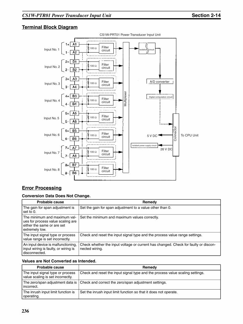
CS1W-PTR01 Power Transducer Input Unit Section 2-14
Terminal Block Diagram
Error Processing
Conversion Data Does Not Change.
Values are Not Converted as Intended.
Probable cause Remedy
The gain for span adjustment is set to 0.
Set the gain for span adjustment to a value other than 0.
The minimum and maximum val-ues for process value scaling are either the same or are set extremely low.
Set the minimum and maximum values correctly.
The input signal type or process value range is set incorrectly.
Check and reset the input signal type and the process value range settings.
An input device is malfunctioning, input wiring is faulty, or wiring is disconnected.
Check whether the input voltage or current has changed. Check for faulty or discon-nected wiring.
Probable cause Remedy
The input signal type or process value scaling is set incorrectly.
Check and reset the input signal type and the process value scaling settings.
The zero/span adjustment data is incorrect.
Check and correct the zero/span adjustment settings.
The inrush input limit function is operating.
Set the inrush input limit function so that it does not operate.
A/D converter
Digital computation circuit
5 V DC
26 V DCIsolated power supply circuit
To CPU Unit
Input No. 2
Input No. 1
Input No. 3
Input No. 4
Input No. 6
Input No. 5
Input No. 7
Input No. 8
CS1W-PRT01 Power Transducer Input Unit
Filter circuit Isolation circuit
Filter circuit
Filter circuit
Filter circuit
Filter circuit
Filter circuit
Filter circuit
Filter circuit
Con
nect
or
Mul
tiple
xer
100 Ω
100 Ω
100 Ω
100 Ω
100 Ω
100 Ω
100 Ω
100 Ω
−
−
−
−
−
−
−
−
236

CS1W-PTR01 Power Transducer Input Unit Section 2-14
Converted Values are Unstable.
Probable cause Remedy
Input signals are being affected by external noise.
Change the connection paths of the input signal lines. (Separate them from sources of noise or use shielded cable.)
Insert 0.01-µF to 0.1-µF ceramic capacitors between the positive and negative input terminals.
The scaling value is greater than the Unit’s resolution.
Reduce the scaling value.
237

CS1W-PTR02 Analog Input Unit (100 mV) Section 2-15
2-15 CS1W-PTR02 Analog Input Unit (100 mV)Overview
The CS1W-PTR02 Analog Input Unit provides up to eight inputs of 0 to100 mV or –100 to 100 mA, and sends the data to the CPU Unit each cycle.
System Configuration
Features• Up to eight inputs of 0 to 100 mV or –100 to 100 mV can be separately
connected.• Scaling values are sent to the CPU Unit in four digits hexadecimal.• The inrush input limit function temporarily limits the process value input to
a given set value when it increases from a low value (2%), in order to pre-vent process values from being jumped up by an inrush current when themotor is started up, and so on. (This function is available for inputs of 0 to100 mV only.)
• Two values for each process value alarm input.• ON-delay timer for process value alarm.• Mean value processing (for four values).• Zero/span adjustment capability during operation.
Model Information
CS1W-PTR02
Eight DC inputs (0 to 100 mV or −100 to 100 mV)
CS1W-PTR02
Unit classification Model number Inputs Input types
CS-series Special I/O Unit CS1W-PTR02 8 Either of the following can be selected separately: 0 to 100 mV, or –100 to 100 mV.
238

CS1W-PTR02 Analog Input Unit (100 mV) Section 2-15
Block Diagram (Order of Processing)The processing for the eight inputs is as shown in the following diagram.
CPU Unit CIO Area
Process value Process value alarm
Analog Input Unit
Process value alarm
Output limit: −15% to +115%
Inrush input limit
Zero/span adjustment
Process value scaling
Input calculationsInput range
A/D conversion, moving average (for four values)
Sensor/signal converter
0 to 100 mV, −100 to 100 mV
I/O refresh
Can be used when input range is 0 to 100 mV.
H, L
239

CS1W-PTR02 Analog Input Unit (100 mV) Section 2-15
SpecificationsItem Specifications
Model CS1W-PTR02
Applicable PLC CS Series
Unit classification CS-series Special I/O Unit
Mounting position CS-series CPU Rack or CS-series Expansion Rack (Cannot be mounted to C200H Expansion I/O Rack or SYSMAC BUS Remote I/O Slave Rack.)
Maximum number of Units 80 (within the allowable current consumption and power consumption range)
Unit numbers 00 to 95 (Cannot duplicate Special I/O Unit numbers.)
Areas for data exchange with CPU Unit
Special I/O Unit Area
10 words/Unit
Analog Input Unit to CPU Unit:All process values, process value alarms (L, H)
DM Area words allocated to Special I/O Units
100 words/UnitCPU Unit to Analog Input Unit:Input signal type, scaling of process value in industrial units, process value alarm set-ting (L, H), inrush input upper limit, inrush input upper limit time, zero/span adjustment value, etc.
Number of inputs 8
Input signal type Either 0 to 100 mV or –100 to 100 mV. Input signal type and scaling to industrial units are separate for each of the 8 inputs.
Note Input signal type and scaling to industrial units are set in the DM Area.
Example:Input signal type: 0 to 100 mV; industrial unit scaling: 0 to 500. DM Area settings are as follows:Input signal type: 0 (0000 hex)Industrial unit maximum value stored: 500 (01F4 hex)Industrial unit minimum value stored: 0 (0000 hex)
User-defined scaling in industrial units
Scaling required for the above input sig-nals. (Any minimum and maximum values can be set.) (8 inputs set separately.)
Data storage in the CIO Area The value derived from carrying out the following processing in order of the pro-cess value data is stored in four digits hexadecimal (binary values) in the allo-cated words in the CIO Area.1) Mean value processing → 2) Scaling → 3) Zero/span adjustment → 4) Inrush input limit → 5) Output limits
Accuracy (25°C) ±0.2% of full scale
Temperature coefficient ±0.015%/°C of full scale
Resolution 1/4,096 of full scale
Input signal range For 0 to 100 mV: –15 to 115%; for –100 to 100 mV: –7.5 to 107.5%
Input impedance Balanced: 1 MΩ min. (typical); unbalanced: 20 kΩ (typical)
Warmup time 10 min
Response time 1.2 s (travel time from input 0% to 90%, for step input)
Conversion period 200 ms/8 inputs
Maximum time to store data in CPU Unit
Conversion period + one CPU Unit cycle
Input error detection None
Operation at input disconnection Undefined
Function Inrush input limit
When the process value is increased from 2% or less, the inrush input limit function limits the increase for a set time. (It is available only for inputs of 0 to 100 mV.) This function can be used to prevent sudden process value increases due to inrush cur-rents caused by motor startup and so on.Upper limit value: –32,000 to 32,000Upper limit time: 0 to 100 s
Process value alarm
Process value 2-point alarm (H, L), hysteresis, and ON-delay timer (0 to 60 s) are available.
Mean value processing (input filter)
Calculates the moving average for the past four process values (every 200 ms), and stores that value in the CIO Area as the process value.
Isolation Between inputs: No isolationBetween input terminals and PLC signals: Isolation by transformer and photocoupler.
240

CS1W-PTR02 Analog Input Unit (100 mV) Section 2-15
DM Area Allocationsm = D20000 + unit number × 100 (unit number: 0 to 95)
Insulation resistance 20 MΩ (at 500 V DC) between inputs and internal PLC signals.
Dielectric strength Between inputs and internal PLC signals: 1,000 V AC, at 50/60 Hz, for 1 min, leakage current: 10 mA max.
External connections Terminal block (detachable)
Unit number settings Set by rotary switches on front panel, from 0 to 95.
Indicators Three LED indicators on front panel (for normal operation, errors detected at the Ana-log Input Unit, and errors related to the CPU Unit).
Front panel connector Sensor input connector terminal block (detachable)
Effect on CPU Unit cycle time 0.3 ms
Current consumption 5 V DC at 150 mA max., 26 V DC at 80 mA max.
Dimensions 35 × 130 × 126 mm (W × H × D)Note The height including the Backplane is 145 mm.
Weight 450 g max.
Standard accessories None
Item Specifications
DM Area address Data range Default Data contents
Input No. 1
Input No. 2
Input No. 3
Input No. 4
Input No. 5
Input No. 6
Input No. 7
Input No. 8
Deci-mal
Hexadecimal
m 12345, 0
3039, 0000 hex
0000 hex Default block read commandSpecifies the direction of data transfer when the PLC is turned ON or the Unit is restarted for DM words m+2 to m+89.• 12345 (3039 hex): The data in
words m+2 to m+89 is transferredfrom the Analog Input Unit to theCPU Unit. When the transfer iscompleted, the value will become0000 hex.
• Other than 12345 (such as 0000hex): The data in the allocatedwords of DM Area is transferredfrom the CPU Unit to the AnalogInput Unit.
Setting Group 1 (continuously refreshed area): Parameters that are continuously refreshed during PLC operation (regardless of the CPU Unit’s operation mode)
Process value alarm settings
m + 2 m + 6 m + 10
m + 14
m + 18
m + 22
m + 26
m + 30
–32768 to 32767
8000 to FFFF hex, 0000 to 7FFF hex
4000 (0FA0 hex)
Process value H (high limit) alarm setting(Set at process value scaling value.)
m + 3 m + 7 m + 11
m + 15
m + 19
m + 23
m + 27
m + 31
–32768 to 32767
8000 to FFFF hex, 0000 to 7FFF hex
0 (0000 hex)
Process value L (low limit) alarm setting(Set at process value scaling value.)
Zero/span adjustment
m + 4 m + 8 m + 12
m + 16
m + 20
m + 24
m + 28
m + 32
0 to 32000
0000 to 7D00 hex
10000 (2710 hex)
Gain for span adjustment(set value x 0.0001)
m + 5 m + 9 m + 13
m + 17
m + 21
m + 25
m + 29
m + 33
–32000 to 32000
8300 to FFFF hex, 0000 to 7D00 hex
0 (0000 hex)
Zero adjustment value(Set at process value scaling value.)
Setting Group 2 (initial settings area): Parameters that are transferred one time from the CPU Unit to the Analog Input Unit if word m contains other than 12345 when the PLC is turned ON or the Analog Input Unit is restarted.
m + 34
m + 41
m + 48
m + 55
m + 62
m + 69
m + 76
m + 83
0, 1 0000 to 0001 hex
0 (0000 hex)
Input signal type0: 0 to 100 mV1: –100 to 100 mV
241

CS1W-PTR02 Analog Input Unit (100 mV) Section 2-15
Note The ERC indicator on the Unit’s front panel will light if an out-of-range settingis made in either Setting Group 1 or 2. The offset from word m to the first wordcontaining the out-of-range error will be stored as the Address of Data RangeError in the DM Area in four digits hexadecimal. For more information, refer to1-6 Error Processing.
Process value scaling
m + 35
m + 42
m + 49
m + 56
m + 63
m + 70
m + 77
m + 84
–32000 to 32000
8300 to FFFF hex, 0000 to 7D00 hex
4000 (0FA0 hex)
Value stored for maximum value in range (span)
m + 36
m + 43
m + 50
m + 57
m + 64
m + 71
m + 78
m + 85
–32000 to 32000
8300 to FFFF hex, 0000 to 7D00 hex
0 (0000 hex)
Value stored for minimum value in range (zero)
Alarm supplementary functions
m + 37
m + 44
m + 51
m + 58
m + 65
m + 72
m + 79
m + 86
0 to 32000
0000 to 7D00 hex
40 (0028 hex)
Alarm hysteresis(Set at process value scaling value.)
m + 38
m + 45
m + 52
m + 59
m + 66
m + 73
m + 80
m + 87
0 to 60 0000 to 003C hex
0 (0000 hex)
Alarm ON-delay time (Unit: s)
Inrush input limit function
m + 39
m + 46
m + 53
m + 60
m + 67
m + 74
m + 81
m + 88
0 to 100
0000 to 0064 hex
0 (0000 hex)
Inrush upper limit time (Unit: s)0: No limit
m + 40
m + 47
m + 54
m + 61
m + 68
m + 75
m + 82
m + 89
–32000 to 32000
8300 to FFFF hex, 0000 to 7D00 hex
4000 (0FA0 hex)
Inrush upper limit value
Storage parameter
m + 90
m + 91
m + 92
m + 93
m + 94
m + 95
m + 96
m + 97
0 to 89 0000 to 0059 hex
0 (0000 hex)
Address of Data Range Error (See note.)
DM Area address Data range Default Data contents
Input No. 1
Input No. 2
Input No. 3
Input No. 4
Input No. 5
Input No. 6
Input No. 7
Input No. 8
Deci-mal
Hexadecimal
242
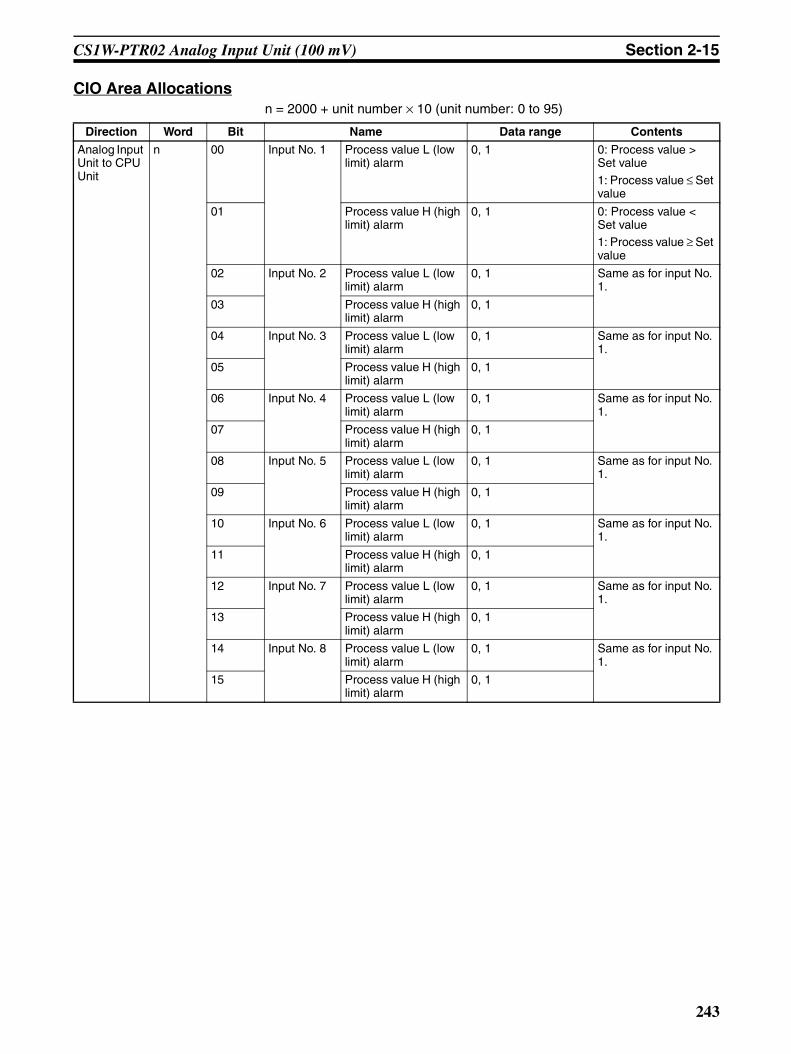
CS1W-PTR02 Analog Input Unit (100 mV) Section 2-15
CIO Area Allocationsn = 2000 + unit number × 10 (unit number: 0 to 95)
Direction Word Bit Name Data range Contents
Analog Input Unit to CPU Unit
n 00 Input No. 1 Process value L (low limit) alarm
0, 1 0: Process value > Set value
1: Process value ≤ Set value
01 Process value H (high limit) alarm
0, 1 0: Process value < Set value1: Process value ≥ Set value
02 Input No. 2 Process value L (low limit) alarm
0, 1 Same as for input No. 1.
03 Process value H (high limit) alarm
0, 1
04 Input No. 3 Process value L (low limit) alarm
0, 1 Same as for input No. 1.
05 Process value H (high limit) alarm
0, 1
06 Input No. 4 Process value L (low limit) alarm
0, 1 Same as for input No. 1.
07 Process value H (high limit) alarm
0, 1
08 Input No. 5 Process value L (low limit) alarm
0, 1 Same as for input No. 1.
09 Process value H (high limit) alarm
0, 1
10 Input No. 6 Process value L (low limit) alarm
0, 1 Same as for input No. 1.
11 Process value H (high limit) alarm
0, 1
12 Input No. 7 Process value L (low limit) alarm
0, 1 Same as for input No. 1.
13 Process value H (high limit) alarm
0, 1
14 Input No. 8 Process value L (low limit) alarm
0, 1 Same as for input No. 1.
15 Process value H (high limit) alarm
0, 1
243
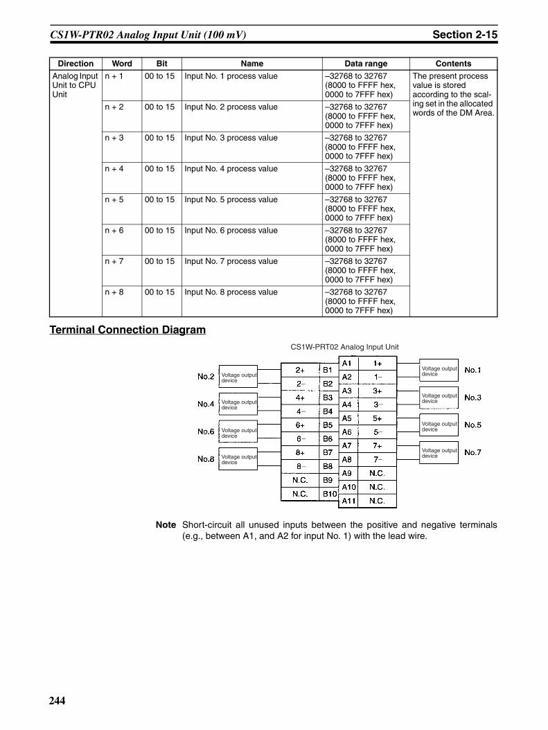
CS1W-PTR02 Analog Input Unit (100 mV) Section 2-15
Terminal Connection Diagram
Note Short-circuit all unused inputs between the positive and negative terminals(e.g., between A1, and A2 for input No. 1) with the lead wire.
Analog Input Unit to CPU Unit
n + 1 00 to 15 Input No. 1 process value –32768 to 32767 (8000 to FFFF hex, 0000 to 7FFF hex)
The present process value is stored according to the scal-ing set in the allocated words of the DM Area.
n + 2 00 to 15 Input No. 2 process value –32768 to 32767 (8000 to FFFF hex, 0000 to 7FFF hex)
n + 3 00 to 15 Input No. 3 process value –32768 to 32767 (8000 to FFFF hex, 0000 to 7FFF hex)
n + 4 00 to 15 Input No. 4 process value –32768 to 32767 (8000 to FFFF hex, 0000 to 7FFF hex)
n + 5 00 to 15 Input No. 5 process value –32768 to 32767 (8000 to FFFF hex, 0000 to 7FFF hex)
n + 6 00 to 15 Input No. 6 process value –32768 to 32767 (8000 to FFFF hex, 0000 to 7FFF hex)
n + 7 00 to 15 Input No. 7 process value –32768 to 32767 (8000 to FFFF hex, 0000 to 7FFF hex)
n + 8 00 to 15 Input No. 8 process value –32768 to 32767 (8000 to FFFF hex, 0000 to 7FFF hex)
Direction Word Bit Name Data range Contents
CS1W-PRT02 Analog Input Unit
Voltage output device
Voltage output device
Voltage output device
Voltage output device
Voltage output device
Voltage output device
Voltage output device
Voltage output device
−
−
−
−
−
−
−
−
244
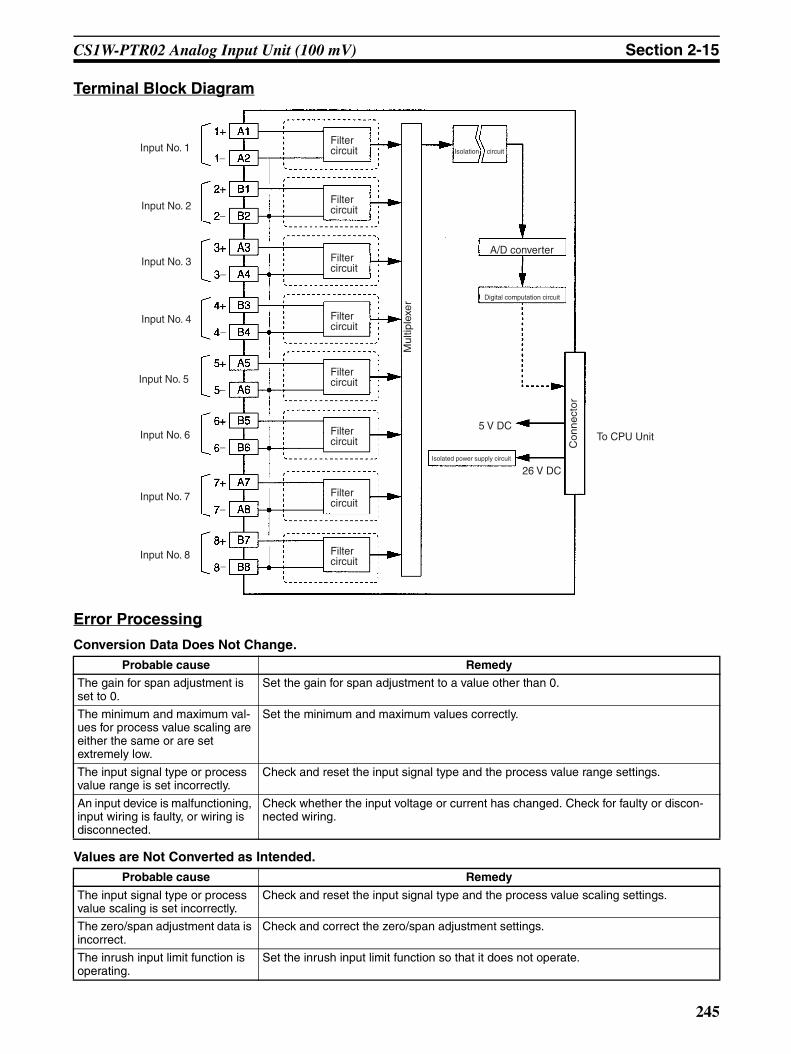
CS1W-PTR02 Analog Input Unit (100 mV) Section 2-15
Terminal Block Diagram
Error Processing
Conversion Data Does Not Change.
Values are Not Converted as Intended.
Probable cause Remedy
The gain for span adjustment is set to 0.
Set the gain for span adjustment to a value other than 0.
The minimum and maximum val-ues for process value scaling are either the same or are set extremely low.
Set the minimum and maximum values correctly.
The input signal type or process value range is set incorrectly.
Check and reset the input signal type and the process value range settings.
An input device is malfunctioning, input wiring is faulty, or wiring is disconnected.
Check whether the input voltage or current has changed. Check for faulty or discon-nected wiring.
Probable cause Remedy
The input signal type or process value scaling is set incorrectly.
Check and reset the input signal type and the process value scaling settings.
The zero/span adjustment data is incorrect.
Check and correct the zero/span adjustment settings.
The inrush input limit function is operating.
Set the inrush input limit function so that it does not operate.
A/D converter
Digital computation circuit
5 V DC
26 V DCIsolated power supply circuit
To CPU Unit
Input No. 2
Input No. 1
Input No. 3
Input No. 4
Input No. 6
Input No. 5
Input No. 7
Input No. 8
Filter circuit Isolation circuit
Filter circuit
Filter circuit
Filter circuit
Filter circuit
Filter circuit
Filter circuit
Filter circuit
Con
nect
or
Mul
tiple
xer
−
−
−
−
−
−
−
−
245

CS1W-PTR02 Analog Input Unit (100 mV) Section 2-15
Converted Values are Unstable.
Probable cause Remedy
Input signals are being affected by external noise.
Change the connection paths of the input signal lines. (Separate them from sources of noise or use shielded cable.)
Insert 0.01-µF to 0.1-µF ceramic capacitors between the positive and negative input terminals.
The scaling value is greater than the Unit’s resolution.
Reduce the scaling value.
246
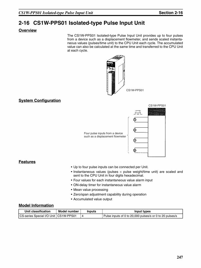
CS1W-PPS01 Isolated-type Pulse Input Unit Section 2-16
2-16 CS1W-PPS01 Isolated-type Pulse Input UnitOverview
The CS1W-PPS01 Isolated-type Pulse Input Unit provides up to four pulsesfrom a device such as a displacement flowmeter, and sends scaled instanta-neous values (pulses/time unit) to the CPU Unit each cycle. The accumulatedvalue can also be calculated at the same time and transferred to the CPU Unitat each cycle.
System Configuration
Features• Up to four pulse inputs can be connected per Unit.• Instantaneous values (pulses × pulse weight/time unit) are scaled and
sent to the CPU Unit in four digits hexadecimal.• Four values for each instantaneous value alarm input• ON-delay timer for instantaneous value alarm• Mean value processing• Zero/span adjustment capability during operation• Accumulated value output
Model Information
CS1W-PPS01
CS1W-PPS01
Four pulse inputs from a device such as a displacement flowmeter
Unit classification Model number Inputs Input types
CS-series Special I/O Unit CS1W-PPS01 4 Pulse inputs of 0 to 20,000 pulses/s or 0 to 20 pulses/s
247

CS1W-PPS01 Isolated-type Pulse Input Unit Section 2-16
Block Diagram (Order of Processing)The processing for the four inputs is as shown in the following diagram.
Pulse weight conversion(pulse scaling)
Accumulation reset for all inputs at restart.
Instantaneous value (pulse × pulse weight per time unit) scaling
Instantaneous value (pulses × pulse weight per time unit) conversion
Instantaneous value (pulses × pulse weight per time unit) average
Use when the weight/pulse (pulse weight) from the Sensor is a fraction (not an exponent of 10), and the accumulated value from the Pulse Input Unit in the CPU Unit is used as is (without scaling). Do not use at any other time.
CPU Unit CIO Area
Instantaneous value Instantaneous value alarm
Output limit: −15% to +115%
Zero/span adjustment
I/O refresh
Accumulated value Accumulation Reset Flag
For each input For all inputs
Pulse Input Unit
Instantaneous value alarm ON for 10 s at reset.
Stepdown
Differential accumulation
HH, H, L, LL
Pulse generator Flow, mass, power, rotation pulses, etc.
248

CS1W-PPS01 Isolated-type Pulse Input Unit Section 2-16
SpecificationsItem Specifications
Model CS1W-PPS01
Applicable PLC CS-series
Unit classification CS-series Special I/O Unit
Mounting position CS-series CPU Rack or CS-series Expansion Rack (Cannot be mounted to C200H Expansion I/O Rack or SYSMAC BUS Remote I/O Slave Rack.)
Maximum number of Units 80 (within the allowable current consumption and power consumption range)
Unit numbers 00 to 95 (Cannot duplicate Special I/O Unit numbers.)
Areas for data exchange with CPU Unit
Special I/O Unit Area
10 words/Unit
Pulse Input Unit to CPU Unit:All process values, process value alarms (LL, L, H, HH), accumulated values, Accu-mulation Reset Bit
DM Area words allocated to Special I/O Units
100 words/UnitCPU Unit to Pulse Input Unit:Instantaneous value conversion coefficient, instantaneous value scaling, pulse weight, number of values for moving average, instantaneous value alarm settings (LL, L, H, HH), zero/span adjustment, etc.
Number of pulse inputs 4
Pulse input type Voltage input, no-voltage semiconductor input, contact input (selected individually for each of 4 inputs, according to connection terminals)
No-voltage semiconductor input: Connected to voltage input terminals (between Fn+ and COMn).
Maximum coefficient speed: 20,000 pulses/s (duty ratio: 50%)Detection voltage: 4 V DCShort-circuit current between terminals: 1.2 mA DCON resistance: 0.8 kΩ max.OFF resistance: 5.0 kΩ min.
Voltage input: Connected to voltage input terminals (between Fn+ and COMn).Waveform: Square waveMaximum coefficient speed: 20,000 pulses/s (duty ratio: 50%)ON voltage: 0 to 1 VOFF voltage: 3 to 30 V
Contact input: Connected to contact input terminals (between Sn+ and COMn).Maximum coefficient speed: 20 pulses/s (duty ratio: 50%)Detection voltage: 8 V DCShort-circuit current between terminals: 2.4 mA DCON resistance: 0.8 kΩ max.OFF resistance: 5.0 kΩ min.
Sensor power supply For no-voltage semiconductor inputs, etc., a 12-V DC power supply can be provided for the sensors that are the pulse sources.Output voltage: 12 V DC ±15%Current capacity: 30 mA max.Limit current when short-circuited: 31 to 55 mAAllowable short-circuit time: No limit
Accumulation conversion period 100 ms/4 inputs
Maximum time to store data in CPU Unit
Conversion period + one CPU Unit cycle
249

CS1W-PPS01 Isolated-type Pulse Input Unit Section 2-16
Function Instantaneous value output
Conversion to instantaneous values
This function can be used to count the number of pulses per time unit, and to convert the values to instantaneous values (pulses x pulse weight / time unit). Any of the following can be selected as the time unit: 1 s, 3 s, 10 s, 30 s, or 60 s. (The time unit is set in the DM Area.)
Note 1 Errors and fluctuations will increase when the input signal pulse rate is low, so specify a longer time unit.
Note 2 The instantaneous value is only refreshed at intervals of the time unit set. Therefore, when the Unit is restarted, the instantaneous value will be 0000 until the time set as the time unit has elapsed.
Note 3 When pulse weight conversion is used for accumulated values, the number of pulses obtained by multiplying the actual number of input pulses by the pulse weight (0.1000 to 3.2000) for one time unit is used.
Instantaneous value scaling
This function can be used for scaling instantaneous values (pulses x pulse weight/time unit), i.e., setting data with respect to a maximum value, and storing them in the allocated words of the CIO Area.
• When instantaneous value (pulses x pulse weight/time unit) is 100% input: Can be set from 0.001 pulses/time unit to 32,000 pulses/time unit.
• Maximum value for Instanta-neous value scaling (industrial units): Scaling of the above instanta-neous value (100% input) is possible from –32,000 to 32,000 (8300 to FFFF, 0000 to 7D00 hex).
Note When pulse weight con-version is used for accu-mulated values, scaling is already performed for each pulse, so an expo-nent of 10 of the industrial unit is set in the instanta-neous value (pulses x pulse weight per time unit) for a 100% input.
Example 1:To obtain a pulse input of 0 to 2,000 pulses/s for a flow of 0 to 300.0 ml/s:
Time unit: 1 sInstantaneous value 100% input: 2,000Maximum value for instanta-neous value scaling (industrial units): 3,000
Example 2:When pulse inputs at 0 to 2,000 pulses/s are obtained for a flow-rate of 0 to 300.0 ml/s, and the pulse weight function is used for totaling:There are 0.15 ml per pulse, so the pulse weight = 0.15.
For a flowrate of 0 to 300.0 ml/s, 0 to 2,000 x 0.15 = 300 pulses/s. Therefore,
Time unit: 1 sInstantaneous value 100% input: 300Maximum value for instanta-neous value scaling (industrial units): 3,000
Data storage in the CIO Area
The value derived from carrying out the following processing in order of the instantaneous value (pulses x pulse weight/time unit) is stored in four digits hexadeci-mal (binary values) in the allo-cated words in the CIO Area.1) Mean value processing → 2) Instantaneous value scaling → 3) Scaling → 4) Zero/span adjustment → 5) Output limits
Mean value pro-cessing (input fil-ter)
Calculates the moving average for the specified number of past instantaneous values (1 to 16), and stores that value in the CIO Area as the instantaneous value.
Instantaneous value alarm
Instantaneous value 4-point alarm (HH, H, L, LL), hysteresis, and ON-delay timer (0 to 60 s) are available.
Item Specifications
250

CS1W-PPS01 Isolated-type Pulse Input Unit Section 2-16
Function Accumulated output
Pulse weight conversion
Performs scaling for a single pulse. Use for the accumulated value when the pulse weight (weight/pulse) is a fraction (not an exponent of 10). (See note.)The pulse weight (0.1 to 3.2) is multiplied by the actual number of pulses input. This number of pulses is used as the input for conver-sion to instantaneous values (pulses x pulse weight per time unit) and the input for totaling prior to stepdown.Example: When the pulse weight from the flowmeter is 0.26 ml/pulse, the pulse weight is set to 0.26. When one pulse (0.26 ml) is input, it is treated as a 0.26 pulse, and when two pulses (0.52 ml) are input, they are treated as a 0.52 pulse.The weight per pulse becomes 1 ml, so to calculate in the CPU Unit the simple (unscaled) value in industrial units (ml) based on the accumulated value from the Pulse Input Unit (value in words n+5 to n+8), the value can be calculated simply using 1 ml/pulse.Note When the accumulated value from the Pulse Input Unit in the
CPU Unit is not used (i.e., when only the instantaneous value is used), pulse weight conversion is not required. Use instantaneousness value scaling to convert to industrial units.
Accumulated value
The accumulated number of pulses (0 to 9,999 pulses) for each input is stored in the allocated words of the CIO Area. When 9,999 is exceeded, the value returns to 0 and starts counting again.Note When pulse weight conversion is used, the accumulated
value for the number of pulses obtained by multiplying the actual number of input pulses by the pulse weight (0.1000 to 3.2000) is used.
Stepdown When the accumulated value is used, this function prevents accu-mulated value overflow by reducing the number of input pulses. The actual number of input pulses is multiplied by one of four fac-tors (x1, x0.1, x0.01, or x0.001), and the number of input pulses accumulated is then based on that value.Note This stepdown function operates only for accumulated val-
ues, and not for instantaneous values. When the pulse weight conversion function is used, it uses for the number of pulses obtained by multiplying the actual number of input pulses by the pulse weight (0.1000 to 3.2000).
Isolation Between inputs and between input terminals and PLC signals: Isolation by trans-former and photocoupler
Insulation resistance 20 MΩ (at 500 V DC) between inputs
Dielectric strength Between inputs: 1,000 V AC, at 50/60 Hz, for 1 min, leakage current 10 mA max.
External connections Terminal block (detachable)
Unit number settings Set by rotary switches on front panel, from 0 to 95.
Indicators Three LED indicators on front panel (for normal operation, errors detected at the Pulse Input Unit, and errors related to the CPU Unit).
Front panel connector Sensor input connector terminal block (detachable)
Effect on CPU Unit cycle time 0.3 ms
Current consumption 5 V DC at 200 mA max., 26 V DC at 160 mA max.
Warmup time 10 min
Dimensions 35 × 130 × 126 mm (W × H × D)Note The height including the Backplane is 145 mm.
Weight 450 g max.
Standard accessories None
Item Specifications
251
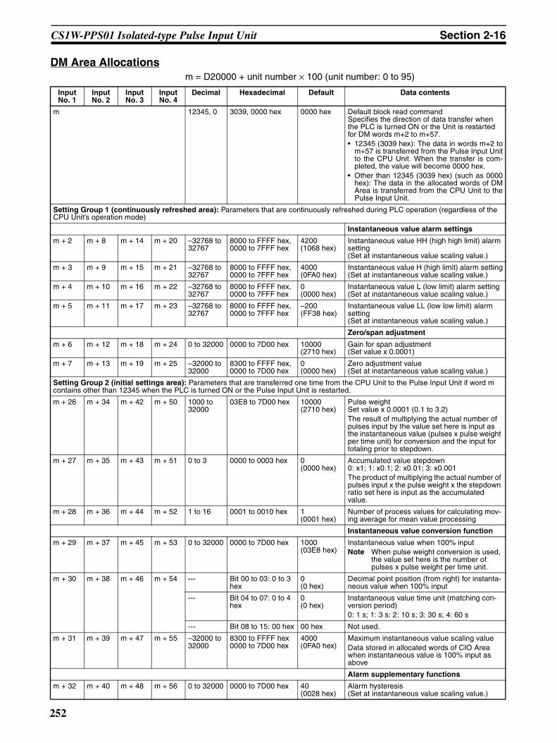
CS1W-PPS01 Isolated-type Pulse Input Unit Section 2-16
DM Area Allocationsm = D20000 + unit number × 100 (unit number: 0 to 95)
Input No. 1
Input No. 2
Input No. 3
Input No. 4
Decimal Hexadecimal Default Data contents
m 12345, 0 3039, 0000 hex 0000 hex Default block read commandSpecifies the direction of data transfer when the PLC is turned ON or the Unit is restarted for DM words m+2 to m+57.• 12345 (3039 hex): The data in words m+2 to
m+57 is transferred from the Pulse Input Unitto the CPU Unit. When the transfer is com-pleted, the value will become 0000 hex.
• Other than 12345 (3039 hex) (such as 0000hex): The data in the allocated words of DMArea is transferred from the CPU Unit to thePulse Input Unit.
Setting Group 1 (continuously refreshed area): Parameters that are continuously refreshed during PLC operation (regardless of the CPU Unit’s operation mode)
Instantaneous value alarm settings
m + 2 m + 8 m + 14 m + 20 –32768 to 32767
8000 to FFFF hex, 0000 to 7FFF hex
4200 (1068 hex)
Instantaneous value HH (high high limit) alarm setting(Set at instantaneous value scaling value.)
m + 3 m + 9 m + 15 m + 21 –32768 to 32767
8000 to FFFF hex, 0000 to 7FFF hex
4000 (0FA0 hex)
Instantaneous value H (high limit) alarm setting(Set at instantaneous value scaling value.)
m + 4 m + 10 m + 16 m + 22 –32768 to 32767
8000 to FFFF hex, 0000 to 7FFF hex
0 (0000 hex)
Instantaneous value L (low limit) alarm setting(Set at instantaneous value scaling value.)
m + 5 m + 11 m + 17 m + 23 –32768 to 32767
8000 to FFFF hex, 0000 to 7FFF hex
–200 (FF38 hex)
Instantaneous value LL (low low limit) alarm setting(Set at instantaneous value scaling value.)
Zero/span adjustment
m + 6 m + 12 m + 18 m + 24 0 to 32000 0000 to 7D00 hex 10000 (2710 hex)
Gain for span adjustment(Set value x 0.0001)
m + 7 m + 13 m + 19 m + 25 –32000 to 32000
8300 to FFFF hex, 0000 to 7D00 hex
0 (0000 hex)
Zero adjustment value(Set at instantaneous value scaling value.)
Setting Group 2 (initial settings area): Parameters that are transferred one time from the CPU Unit to the Pulse Input Unit if word m contains other than 12345 when the PLC is turned ON or the Pulse Input Unit is restarted.
m + 26 m + 34 m + 42 m + 50 1000 to 32000
03E8 to 7D00 hex 10000 (2710 hex)
Pulse weightSet value x 0.0001 (0.1 to 3.2)The result of multiplying the actual number of pulses input by the value set here is input as the instantaneous value (pulses x pulse weight per time unit) for conversion and the input for totaling prior to stepdown.
m + 27 m + 35 m + 43 m + 51 0 to 3 0000 to 0003 hex 0 (0000 hex)
Accumulated value stepdown0: x1; 1: x0.1; 2: x0.01; 3: x0.001The product of multiplying the actual number of pulses input x the pulse weight x the stepdown ratio set here is input as the accumulated value.
m + 28 m + 36 m + 44 m + 52 1 to 16 0001 to 0010 hex 1 (0001 hex)
Number of process values for calculating mov-ing average for mean value processing
Instantaneous value conversion function
m + 29 m + 37 m + 45 m + 53 0 to 32000 0000 to 7D00 hex 1000 (03E8 hex)
Instantaneous value when 100% inputNote When pulse weight conversion is used,
the value set here is the number of pulses x pulse weight per time unit.
m + 30 m + 38 m + 46 m + 54 --- Bit 00 to 03: 0 to 3 hex
0 (0 hex)
Decimal point position (from right) for instanta-neous value when 100% input
--- Bit 04 to 07: 0 to 4 hex
0 (0 hex)
Instantaneous value time unit (matching con-version period)0: 1 s; 1: 3 s: 2: 10 s; 3: 30 s; 4: 60 s
--- Bit 08 to 15: 00 hex 00 hex Not used.
m + 31 m + 39 m + 47 m + 55 –32000 to 32000
8300 to FFFF hex0000 to 7D00 hex
4000 (0FA0 hex)
Maximum instantaneous value scaling valueData stored in allocated words of CIO Area when instantaneous value is 100% input as above
Alarm supplementary functions
m + 32 m + 40 m + 48 m + 56 0 to 32000 0000 to 7D00 hex 40 (0028 hex)
Alarm hysteresis(Set at instantaneous value scaling value.)
252

CS1W-PPS01 Isolated-type Pulse Input Unit Section 2-16
Note The ERC indicator on the Unit’s front panel will light if an out-of-range settingis made in either Setting Group 1 or 2. The offset from word m to the first wordcontaining the out-of-range error will be stored as the Address of Data RangeError in the DM Area in four digits hexadecimal. For more information, refer to1-6 Error Processing.
CIO Area Allocationsn = 2000 + unit number × 10 (unit number: 0 to 95)
m + 33 m + 41 m + 49 m + 57 0 to 60 0000 to 003C hex 0 (0000 hex)
Alarm ON-delay time (Unit: s)
Storage parameter
m + 58 m + 59 m + 60 m + 61 0 to 57 0000 to 0039 hex 0 (0000 hex)
Address of Data Range Error (See note.)
Input No. 1
Input No. 2
Input No. 3
Input No. 4
Decimal Hexadecimal Default Data contents
Direction Word Bit Name Data range Contents
Pulse Input Unit to CPU Unit
n 00 Input No. 1 Instantaneous value LL (low low limit) alarm
0, 1 0: Instantaneous value > Set value
1: Instantaneous value ≤ Set value01 Instantaneous value L
(low limit) alarm0, 1
02 Instantaneous value H (high limit) alarm
0, 1 0: Instantaneous value < Set value
1: Instantaneous value ≥ Set value
03 Instantaneous value HH (high high limit) alarm
0, 1
04 Input No. 2 Instantaneous value LL (low low limit) alarm
0, 1 Same as for input No. 1.
05 Instantaneous value L (low limit) alarm
0, 1
06 Instantaneous value H (high limit) alarm
0, 1
07 Instantaneous value HH (high high limit) alarm
0, 1
08 Input No. 3 Instantaneous value LL (low low limit) alarm
0, 1 Same as for input No. 1.
09 Instantaneous value L (low limit) alarm
0, 1
10 Instantaneous value H (high limit) alarm
0, 1
11 Instantaneous value HH (high high limit) alarm
0, 1
12 Input No. 4 Instantaneous value LL (low low limit) alarm
0, 1 Same as for input No. 1.
13 Instantaneous value L (low limit) alarm
0, 1
14 Instantaneous value H (high limit) alarm
0, 1
15 Instantaneous value HH (high high limit) alarm
0, 1
253

CS1W-PPS01 Isolated-type Pulse Input Unit Section 2-16
Note The accumulated value is reset when the PLC is turned ON or when the PulseInput Unit is restarted.
Pulse Input Unit to CPU Unit
n + 1 00 to 15 Input No. 1 instantaneous value –32768 to 32767 (8000 to FFFF hex, 0000 to 7FFF hex)
The present instanta-neous value is stored according to the scal-ing set in the allocated words of the DM Area.
n + 2 00 to 15 Input No. 2 instantaneous value –32768 to 32767 (8000 to FFFF hex, 0000 to 7FFF hex)
n + 3 00 to 15 Input No. 3 instantaneous value –32768 to 32767 (8000 to FFFF hex, 0000 to 7FFF hex)
n + 4 00 to 15 Input No. 4 instantaneous value –32768 to 32767 (8000 to FFFF hex, 0000 to 7FFF hex)
n + 5 00 to 15 Input No. 1 accumulated value 0 to 9999 (0000 to 270F hex)
The accumulated value for the number of pulses (after step-down) is stored here.
n + 6 00 to 15 Input No. 2 accumulated value 0 to 9999 (0000 to 270F hex)
n + 7 00 to 15 Input No. 3 accumulated value 0 to 9999 (0000 to 270F hex)
n + 8 00 to 15 Input No. 4 accumulated value 0 to 9999 (0000 to 270F hex)
n + 9 00 Accumulation Reset Bit 0, 1 When the accumu-lated value is reset, this flag turns ON for 10 s. (See note.)
Direction Word Bit Name Data range Contents
254

CS1W-PPS01 Isolated-type Pulse Input Unit Section 2-16
Terminal Connection Diagram
Note In all of the above cases, leave all unused inputs open between the terminals(e.g., between B1 and B2 for no-voltage semiconductor input No. 1).
No-voltage Semiconductor Input Voltage Input
CS1W-PPS01 Isolated-type Pulse Input Unit CS1W-PPS01 Isolated-type Pulse Input Unit
Voltage pulse generation
Contact Input
CS1W-PPS01 Isolated-type Pulse Input Unit CS1W-PPS01 Isolated-type Pulse Input Unit
3-wire Sensor Input
Internal power supply
Internal power supply
Internal power supply
Internal power supply
−
−
−
−
255
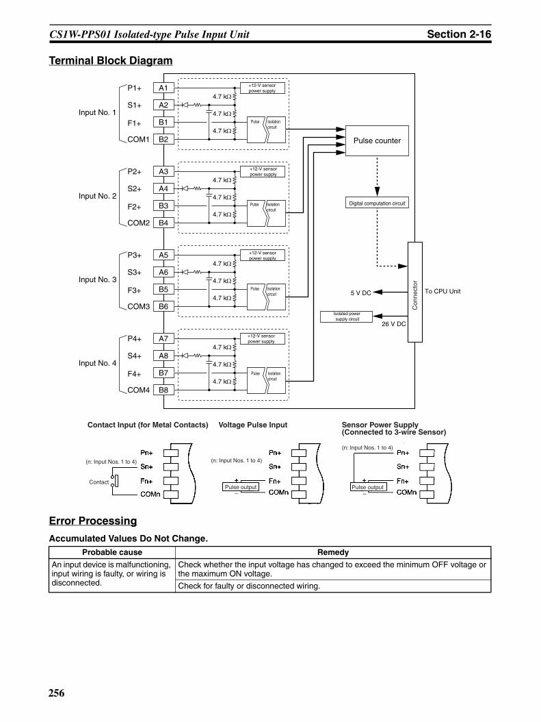
CS1W-PPS01 Isolated-type Pulse Input Unit Section 2-16
Terminal Block Diagram
Error Processing
Accumulated Values Do Not Change.Probable cause Remedy
An input device is malfunctioning, input wiring is faulty, or wiring is disconnected.
Check whether the input voltage has changed to exceed the minimum OFF voltage or the maximum ON voltage.
Check for faulty or disconnected wiring.
A1
A2
B2
P1+
S1+
F1+
COM1
+12-V sensorpower supply
Pulse Isolationcircuit
Digital computation circuit
Isolated power supply circuit
5 V DC
26 V DC
4.7 kΩ
4.7 kΩ
4.7 kΩ
Input No. 1B1
A3
A4
B4
P2+
S2+
F2+
COM2
Input No. 2B3
A5
A6
B6
P3+
S3+
F3+
COM3
Input No. 3B5
A7
A8
B8
P4+
S4+
F4+
COM4
Input No. 4B7
Pulse counter
4.7 kΩ
4.7 kΩ
4.7 kΩ
4.7 kΩ
4.7 kΩ
4.7 kΩ
4.7 kΩ
4.7 kΩ
4.7 kΩ
+12-V sensorpower supply
+12-V sensorpower supply
+12-V sensorpower supply
Pulse Isolationcircuit
Pulse Isolationcircuit
Pulse Isolationcircuit
Con
nect
or
To CPU Unit
(n: Input Nos. 1 to 4) (n: Input Nos. 1 to 4)
Contact Input (for Metal Contacts) Voltage Pulse Input
ContactPulse output
Sensor Power Supply (Connected to 3-wire Sensor)
(n: Input Nos. 1 to 4)
Pulse output− −
256
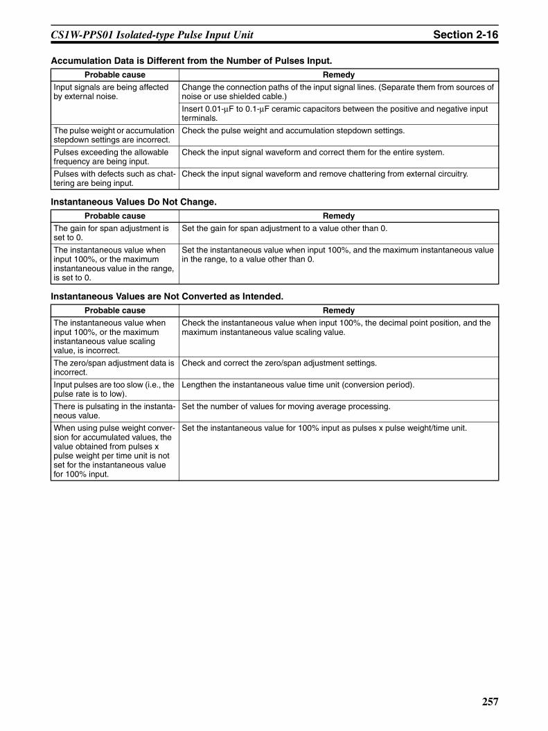
CS1W-PPS01 Isolated-type Pulse Input Unit Section 2-16
Accumulation Data is Different from the Number of Pulses Input.
Instantaneous Values Do Not Change.
Instantaneous Values are Not Converted as Intended.
Probable cause Remedy
Input signals are being affected by external noise.
Change the connection paths of the input signal lines. (Separate them from sources of noise or use shielded cable.)
Insert 0.01-µF to 0.1-µF ceramic capacitors between the positive and negative input terminals.
The pulse weight or accumulation stepdown settings are incorrect.
Check the pulse weight and accumulation stepdown settings.
Pulses exceeding the allowable frequency are being input.
Check the input signal waveform and correct them for the entire system.
Pulses with defects such as chat-tering are being input.
Check the input signal waveform and remove chattering from external circuitry.
Probable cause Remedy
The gain for span adjustment is set to 0.
Set the gain for span adjustment to a value other than 0.
The instantaneous value when input 100%, or the maximum instantaneous value in the range, is set to 0.
Set the instantaneous value when input 100%, and the maximum instantaneous value in the range, to a value other than 0.
Probable cause Remedy
The instantaneous value when input 100%, or the maximum instantaneous value scaling value, is incorrect.
Check the instantaneous value when input 100%, the decimal point position, and the maximum instantaneous value scaling value.
The zero/span adjustment data is incorrect.
Check and correct the zero/span adjustment settings.
Input pulses are too slow (i.e., the pulse rate is to low).
Lengthen the instantaneous value time unit (conversion period).
There is pulsating in the instanta-neous value.
Set the number of values for moving average processing.
When using pulse weight conver-sion for accumulated values, the value obtained from pulses x pulse weight per time unit is not set for the instantaneous value for 100% input.
Set the instantaneous value for 100% input as pulses x pulse weight/time unit.
257

CS1W-PMV01 Isolated-type Analog Output Unit Section 2-17
2-17 CS1W-PMV01 Isolated-type Analog Output UnitOverview
Each cycle, the CS1W-PMV01 Isolated-type Analog Output Unit converts upto four analog output set values from the CPU Unit to either 4 to 20 mA or 1 to5 V, and outputs them. It can also provide answer back for checking actualoutput values.
System Configuration
Features• Outputs in either 4 to 20 mA or 1 to 5 V (set separately for each of the four
outputs) the analog output values set in the allocated words of the CPUUnit’s CIO Area.
• Answer input function.Actual output signals of 4 to 20 mA or 1 to 5 V are checked by being readagain from the output circuit, and are stored in the allocated words in theCIO Area. Mean value processing is also possible.
• Output disconnection detection function (current output only).• Output high/low limit function.• Rate-of-change limit function.• Output hold function when CPU Unit errors occur.
When a CPU Unit fatal error (including FALS execution), or a CPU error inthe CPU Unit occurs, or all outputs are turned OFF with the Output OFFBit, this function can hold either a preset value or the analog output valueprior to the error.
• Zero/span adjustment capability during operation.
Model Information
CS1W-PMV01
CS1W-PMV01
Four analog outputs (4 to 20 mA, 1 to 5 V)
Control terminal
Control terminal
Control terminal
Control terminal
Unit classification Model number Outputs Outputs
CS-series Special I/O Unit CS1W-PMV01 4 4 to 20 mA, 1 to 5 V (separate for each of four outputs)
258
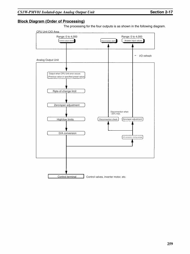
CS1W-PMV01 Isolated-type Analog Output Unit Section 2-17
Block Diagram (Order of Processing)The processing for the four outputs is as shown in the following diagram.
CPU Unit CIO Area
Control output values
Range: 0 to 4,000
Disconnection alarm Answer input values
Range: 0 to 4,000
Analog Output Unit
I/O refresh
Output when CPU Unit error occurs
(Previous value or specified preset value)
Rate-of-change limit
Zero/span adjustment
High/low limits
D/A conversion
Control terminal Control valves, inverter motor, etc.
Disconnection check
Disconnection when −22% max.
Zero/span adjustment
A/D conversion, moving average
259
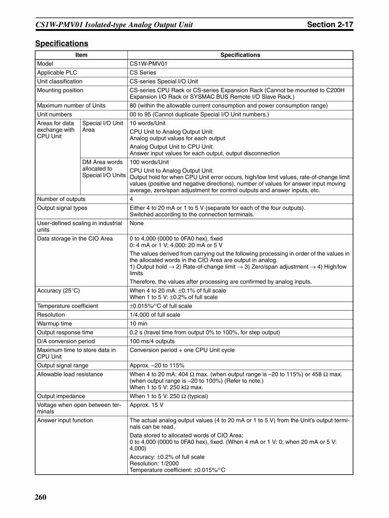
CS1W-PMV01 Isolated-type Analog Output Unit Section 2-17
SpecificationsItem Specifications
Model CS1W-PMV01
Applicable PLC CS Series
Unit classification CS-series Special I/O Unit
Mounting position CS-series CPU Rack or CS-series Expansion Rack (Cannot be mounted to C200H Expansion I/O Rack or SYSMAC BUS Remote I/O Slave Rack.)
Maximum number of Units 80 (within the allowable current consumption and power consumption range)
Unit numbers 00 to 95 (Cannot duplicate Special I/O Unit numbers.)
Areas for data exchange with CPU Unit
Special I/O Unit Area
10 words/Unit
CPU Unit to Analog Output Unit:Analog output values for each outputAnalog Output Unit to CPU Unit:Answer input values for each output, output disconnection
DM Area words allocated to Special I/O Units
100 words/Unit
CPU Unit to Analog Output Unit:Output hold for when CPU Unit error occurs, high/low limit values, rate-of-change limit values (positive and negative directions), number of values for answer input moving average, zero/span adjustment for control outputs and answer inputs, etc.
Number of outputs 4
Output signal types Either 4 to 20 mA or 1 to 5 V (separate for each of the four outputs).Switched according to the connection terminals.
User-defined scaling in industrial units
None
Data storage in the CIO Area 0 to 4,000 (0000 to 0FA0 hex), fixed0: 4 mA or 1 V; 4,000: 20 mA or 5 VThe values derived from carrying out the following processing in order of the values in the allocated words in the CIO Area are output in analog.1) Output hold → 2) Rate-of-change limit → 3) Zero/span adjustment → 4) High/low limitsTherefore, the values after processing are confirmed by analog inputs.
Accuracy (25°C) When 4 to 20 mA: ±0.1% of full scaleWhen 1 to 5 V: ±0.2% of full scale
Temperature coefficient ±0.015%/°C of full scale
Resolution 1/4,000 of full scale
Warmup time 10 min
Output response time 0.2 s (travel time from output 0% to 100%, for step output)
D/A conversion period 100 ms/4 outputs
Maximum time to store data in CPU Unit
Conversion period + one CPU Unit cycle
Output signal range Approx. –20 to 115%
Allowable load resistance When 4 to 20 mA: 404 Ω max. (when output range is –20 to 115%) or 458 Ω max. (when output range is –20 to 100%) (Refer to note.)When 1 to 5 V: 250 kΩ max.
Output impedance When 1 to 5 V: 250 Ω (typical)
Voltage when open between ter-minals
Approx. 15 V
Answer input function The actual analog output values (4 to 20 mA or 1 to 5 V) from the Unit’s output termi-nals can be read.
Data stored to allocated words of CIO Area:0 to 4,000 (0000 to 0FA0 hex), fixed. (When 4 mA or 1 V: 0; when 20 mA or 5 V: 4,000)
Accuracy: ±0.2% of full scaleResolution: 1/2000Temperature coefficient: ±0.015%/°C
260
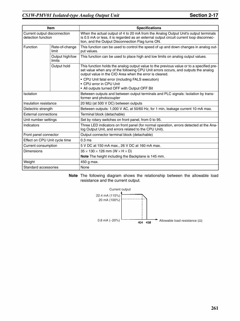
CS1W-PMV01 Isolated-type Analog Output Unit Section 2-17
Note The following diagram shows the relationship between the allowable loadresistance and the current output.
Current output disconnection detection function
When the actual output of 4 to 20 mA from the Analog Output Unit’s output terminals is 0.5 mA or less, it is regarded as an external output circuit current loop disconnec-tion, and the Output Disconnection Flag turns ON.
Function Rate-of-change limit
This function can be used to control the speed of up and down changes in analog out-put values.
Output high/low limits
This function can be used to place high and low limits on analog output values.
Output hold This function holds the analog output value to the previous value or to a specified pre-set value when any of the following CPU Unit errors occurs, and outputs the analog output value in the CIO Area when the error is cleared.• CPU Unit fatal error (including FALS execution)• CPU error in CPU Unit• All outputs turned OFF with Output OFF Bit
Isolation Between outputs and between output terminals and PLC signals: Isolation by trans-former and photocoupler
Insulation resistance 20 MΩ (at 500 V DC) between outputs
Dielectric strength Between outputs: 1,000 V AC, at 50/60 Hz, for 1 min, leakage current 10 mA max.
External connections Terminal block (detachable)
Unit number settings Set by rotary switches on front panel, from 0 to 95.
Indicators Three LED indicators on front panel (for normal operation, errors detected at the Ana-log Output Unit, and errors related to the CPU Unit).
Front panel connector Output connector terminal block (detachable)
Effect on CPU Unit cycle time 0.3 ms
Current consumption 5 V DC at 150 mA max., 26 V DC at 160 mA max.
Dimensions 35 × 130 × 126 mm (W × H × D)Note The height including the Backplane is 145 mm.
Weight 450 g max.
Standard accessories None
Item Specifications
22.4 mA (115%)
Current output
Allowable load resistance (Ω)
20 mA (100%)
0.8 mA (−20%)
261

CS1W-PMV01 Isolated-type Analog Output Unit Section 2-17
Output Values According to CPU Unit StatusAnalog output values from the Analog Output Unit will be as shown in the fol-lowing table, depending on the status of the CPU Unit.
Note Regardless of the CPU Unit’s operation mode (including Program Mode), theanalog output value in the allocated words of the CIO Area is always outputrefreshed. As shown in the above table, however, when the operation mode ischanged to Program Mode, the analog output value in the CIO Area is eithercleared or held depending on the status of the CPU Unit’s I/O Memory HoldFlag (A500.12). In particular, be careful when this flag is ON, because thevalue prior to the mode change will be held and that value will be outputrefreshed.
DM Area Allocationsm = D20000 + unit number × 100 (unit number: 0 to 95)
CPU Unit status Analog output values from Unit
Fatal error (including FALS(007) execution)
The output hold function holds the previous value or a specified preset value.
CPU error
All outputs turned OFF with Output OFF Bit
Change of operation mode from RUN or Monitor to Program
(See note.)
When the CPU Unit’s I/O Memory Hold Flag (A500.12) is OFF.
The output value in the CIO Area is cleared, and that value (0000 hex) is output refreshed.
When the CPU Unit’s I/O Memory Hold Flag (A500.12) is ON.
The output value in the CIO Area is held at the value prior to the operation mode change, and that is output refreshed.
Fatal error or CPU standby after turning ON the power supply
Either 0 mA or 0 V is output.
Special I/O Unit cyclic refresh disabled
Outputs can be refreshed by means of IORF(097) in the ladder diagram program.
Output No. 1
Output No. 2
Output No. 3
Output No. 4
Decimal Hexadecimal Default Data contents
m 12345, 0 3039, 0000 hex 0000 hex Default block read commandSpecifies the direction of data transfer when the PLC is turned ON or the Unit is restarted for DM words m+2 to m+45.• 12345 (3039 hex): The data in words m+2 to
m+45 is transferred from the Analog OutputUnit to the CPU Unit. When the transfer iscompleted, the value will become 0000 hex.
• Other than 12345 (3039 hex) (such as 0000hex): The data in the allocated words of DMArea is transferred from the CPU Unit to theAnalog Output Unit.
Setting Group 1 (continuously refreshed area): Parameters that are continuously refreshed during PLC operation (regardless of the CPU Unit’s operation mode)
Analog output zero/span adjustment
m + 2 m + 6 m + 10 m + 14 0 to 32000 0000 to 7D00 hex 10000 (2710 hex)
Gain for span adjustment(set value x 0.0001)
m + 3 m + 7 m + 11 m + 15 –4000 to 4000
F060 to FFFF hex, 0000 to 0FA0 hex
0 (0000 hex)
Zero adjustment value(Set in units of analog output value resolution.)
Answer input zero/span adjustment
m + 4 m + 8 m + 12 m + 16 0 to 32000 0000 to 7D00 hex 10000 (2710 hex)
Gain for span adjustment(set value x 0.0001)
m + 5 m + 9 m + 13 m + 17 –4000 to 4000
F060 to FFFF hex, 0000 to 0FA0 hex
0 (0000 hex)
Zero adjustment value(Set in units of analog output value resolution.)
262
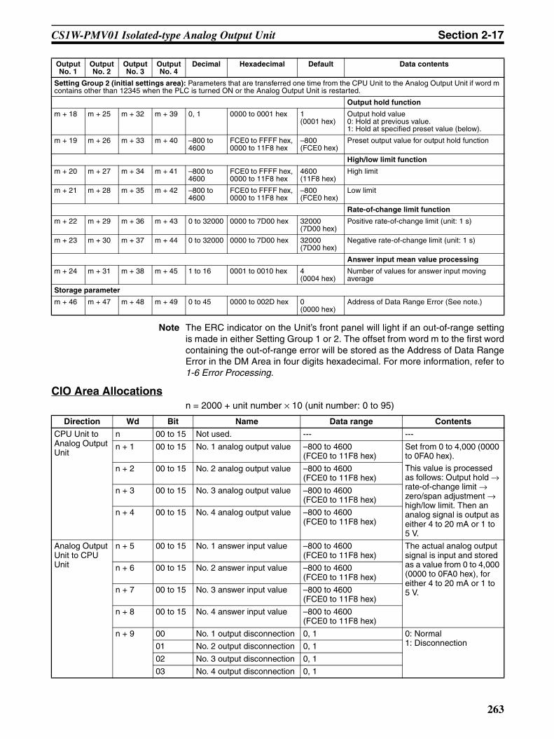
CS1W-PMV01 Isolated-type Analog Output Unit Section 2-17
Note The ERC indicator on the Unit’s front panel will light if an out-of-range settingis made in either Setting Group 1 or 2. The offset from word m to the first wordcontaining the out-of-range error will be stored as the Address of Data RangeError in the DM Area in four digits hexadecimal. For more information, refer to1-6 Error Processing.
CIO Area Allocationsn = 2000 + unit number × 10 (unit number: 0 to 95)
Setting Group 2 (initial settings area): Parameters that are transferred one time from the CPU Unit to the Analog Output Unit if word m contains other than 12345 when the PLC is turned ON or the Analog Output Unit is restarted.
Output hold function
m + 18 m + 25 m + 32 m + 39 0, 1 0000 to 0001 hex 1 (0001 hex)
Output hold value0: Hold at previous value.1: Hold at specified preset value (below).
m + 19 m + 26 m + 33 m + 40 –800 to 4600
FCE0 to FFFF hex, 0000 to 11F8 hex
–800 (FCE0 hex)
Preset output value for output hold function
High/low limit function
m + 20 m + 27 m + 34 m + 41 –800 to 4600
FCE0 to FFFF hex, 0000 to 11F8 hex
4600 (11F8 hex)
High limit
m + 21 m + 28 m + 35 m + 42 –800 to 4600
FCE0 to FFFF hex, 0000 to 11F8 hex
–800 (FCE0 hex)
Low limit
Rate-of-change limit function
m + 22 m + 29 m + 36 m + 43 0 to 32000 0000 to 7D00 hex 32000 (7D00 hex)
Positive rate-of-change limit (unit: 1 s)
m + 23 m + 30 m + 37 m + 44 0 to 32000 0000 to 7D00 hex 32000 (7D00 hex)
Negative rate-of-change limit (unit: 1 s)
Answer input mean value processing
m + 24 m + 31 m + 38 m + 45 1 to 16 0001 to 0010 hex 4 (0004 hex)
Number of values for answer input moving average
Storage parameter
m + 46 m + 47 m + 48 m + 49 0 to 45 0000 to 002D hex 0 (0000 hex)
Address of Data Range Error (See note.)
Output No. 1
Output No. 2
Output No. 3
Output No. 4
Decimal Hexadecimal Default Data contents
Direction Wd Bit Name Data range Contents
CPU Unit to Analog Output Unit
n 00 to 15 Not used. --- ---
n + 1 00 to 15 No. 1 analog output value –800 to 4600 (FCE0 to 11F8 hex)
Set from 0 to 4,000 (0000 to 0FA0 hex).
This value is processed as follows: Output hold → rate-of-change limit → zero/span adjustment → high/low limit. Then an analog signal is output as either 4 to 20 mA or 1 to 5 V.
n + 2 00 to 15 No. 2 analog output value –800 to 4600 (FCE0 to 11F8 hex)
n + 3 00 to 15 No. 3 analog output value –800 to 4600 (FCE0 to 11F8 hex)
n + 4 00 to 15 No. 4 analog output value –800 to 4600 (FCE0 to 11F8 hex)
Analog Output Unit to CPU Unit
n + 5 00 to 15 No. 1 answer input value –800 to 4600 (FCE0 to 11F8 hex)
The actual analog output signal is input and stored as a value from 0 to 4,000 (0000 to 0FA0 hex), for either 4 to 20 mA or 1 to 5 V.
n + 6 00 to 15 No. 2 answer input value –800 to 4600 (FCE0 to 11F8 hex)
n + 7 00 to 15 No. 3 answer input value –800 to 4600 (FCE0 to 11F8 hex)
n + 8 00 to 15 No. 4 answer input value –800 to 4600 (FCE0 to 11F8 hex)
n + 9 00 No. 1 output disconnection 0, 1 0: Normal1: Disconnection01 No. 2 output disconnection 0, 1
02 No. 3 output disconnection 0, 1
03 No. 4 output disconnection 0, 1
263
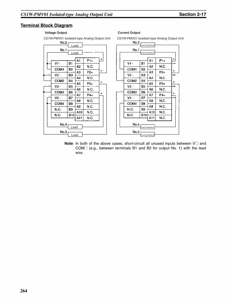
CS1W-PMV01 Isolated-type Analog Output Unit Section 2-17
Terminal Block Diagram
Note In both of the above cases, short-circuit all unused inputs between V@ andCOM@ (e.g., between terminals B1 and B2 for output No. 1) with the leadwire.
Voltage Output Current Output
CS1W-PMV01 Isolated-type Analog Output Unit CS1W-PMV01 Isolated-type Analog Output Unit
Load
Load
Load Load resistance
Load Load resistance
Load resistance
Load resistance
−
−
−
−
−
−
−
−
−
−
−
−
−
−
−
−
264
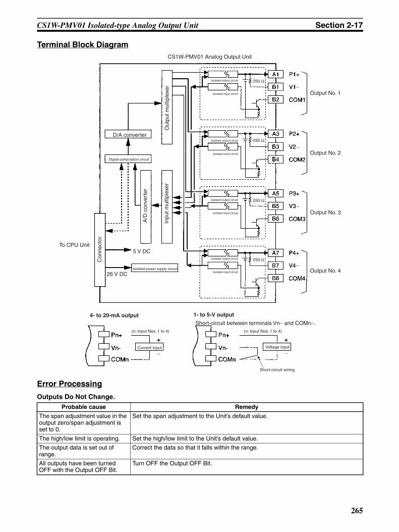
CS1W-PMV01 Isolated-type Analog Output Unit Section 2-17
Terminal Block Diagram
Error Processing
Outputs Do Not Change.
Output No. 1
Digital computation circuit
5 V DC
26 V DCIsolated power supply circuit
To CPU Unit
Isolated input circuit
CS1W-PMV01 Analog Output Unit
Isolated output circuit
Output No. 2
Output No. 3
Output No. 4
D/A converter
Isolated input circuit
Isolated output circuit
Isolated input circuit
Isolated output circuit
Isolated input circuit
Isolated output circuit
Out
put m
ultip
lexe
rIn
put m
ultip
lexe
r
A/D
con
vert
er
Con
nect
or
250 Ω
250 Ω
250 Ω
250 Ω
−
−
−
−
4- to 20-mA output 1- to 5-V output
(n: Input Nos. 1 to 4) (n: Input Nos. 1 to 4)
Short-circuit between terminals Vn− and COMn−.
Current input Voltage input
Short-circuit wiring
−−
Probable cause Remedy
The span adjustment value in the output zero/span adjustment is set to 0.
Set the span adjustment to the Unit’s default value.
The high/low limit is operating. Set the high/low limit to the Unit’s default value.
The output data is set out of range.
Correct the data so that it falls within the range.
All outputs have been turned OFF with the Output OFF Bit.
Turn OFF the Output OFF Bit.
265
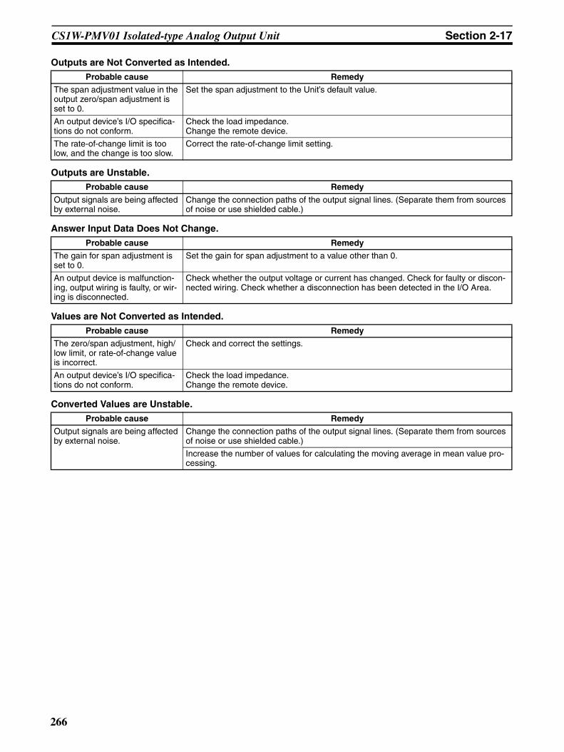
CS1W-PMV01 Isolated-type Analog Output Unit Section 2-17
Outputs are Not Converted as Intended.
Outputs are Unstable.
Answer Input Data Does Not Change.
Values are Not Converted as Intended.
Converted Values are Unstable.
Probable cause Remedy
The span adjustment value in the output zero/span adjustment is set to 0.
Set the span adjustment to the Unit’s default value.
An output device’s I/O specifica-tions do not conform.
Check the load impedance.Change the remote device.
The rate-of-change limit is too low, and the change is too slow.
Correct the rate-of-change limit setting.
Probable cause Remedy
Output signals are being affected by external noise.
Change the connection paths of the output signal lines. (Separate them from sources of noise or use shielded cable.)
Probable cause Remedy
The gain for span adjustment is set to 0.
Set the gain for span adjustment to a value other than 0.
An output device is malfunction-ing, output wiring is faulty, or wir-ing is disconnected.
Check whether the output voltage or current has changed. Check for faulty or discon-nected wiring. Check whether a disconnection has been detected in the I/O Area.
Probable cause Remedy
The zero/span adjustment, high/low limit, or rate-of-change value is incorrect.
Check and correct the settings.
An output device’s I/O specifica-tions do not conform.
Check the load impedance.Change the remote device.
Probable cause Remedy
Output signals are being affected by external noise.
Change the connection paths of the output signal lines. (Separate them from sources of noise or use shielded cable.)
Increase the number of values for calculating the moving average in mean value pro-cessing.
266

CS1W-PMV02 Isolated-type Analog Output Unit Section 2-18
2-18 CS1W-PMV02 Isolated-type Analog Output UnitOverview
Each cycle, the CS1W-PMV02 Isolated-type Analog Output Unit converts upto four analog output set values from the CPU Unit to analog voltage signalsand outputs them.
System Configuration
Features• Outputs the analog output values set in the allocated words of the CPU
Unit’s CIO Area. (Supported output ranges: −10 to 10 V, 0 to 10 V, −5 to5 V, 0 to 5 V, −1 to 1 V, 0 to 1 V.)
• Output high/low limit function.• Rate-of-change limit function.• Output hold function when CPU Unit errors occur.
When a CPU Unit fatal error (including FALS execution), or a CPU error inthe CPU Unit occurs, or all outputs are turned OFF with the Output OFFBit, this function can hold either a preset value or the analog output valueprior to the error.
• Zero/span adjustment capability during operation.
Model Information
CS1W-PMV02
Control terminal
Control terminal
Control terminal
Control terminal
Four analog outputs (0 to 10 V, ±10 V, 0 to 5 V, ±5 V, 0 to 1 V, ±1 V)
CS1W-PMV02
Unit classification Model number Outputs Outputs
CS-series Special I/O Unit CS1W-PMV02 4 −10 to 10 V, 0 to 10 V, −5 to 5 V, 0 to 5 V, −1 to 1 V, 0 to 1 V
267
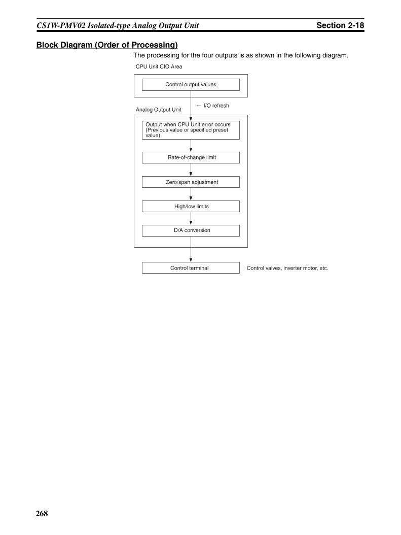
CS1W-PMV02 Isolated-type Analog Output Unit Section 2-18
Block Diagram (Order of Processing)The processing for the four outputs is as shown in the following diagram.
CPU Unit CIO Area
Control output values
I/O refreshAnalog Output Unit
Output when CPU Unit error occurs (Previous value or specified preset value)
Rate-of-change limit
Zero/span adjustment
High/low limits
D/A conversion
Control terminal Control valves, inverter motor, etc.
268
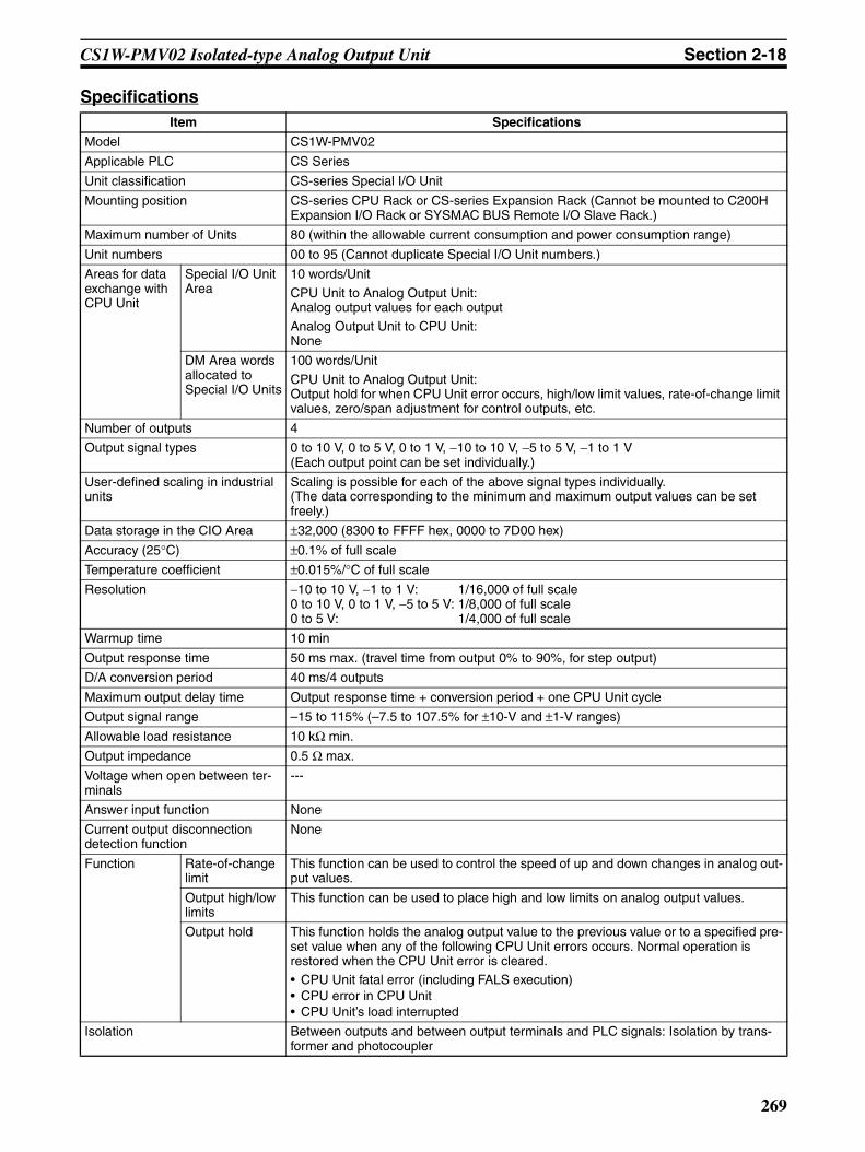
CS1W-PMV02 Isolated-type Analog Output Unit Section 2-18
SpecificationsItem Specifications
Model CS1W-PMV02
Applicable PLC CS Series
Unit classification CS-series Special I/O Unit
Mounting position CS-series CPU Rack or CS-series Expansion Rack (Cannot be mounted to C200H Expansion I/O Rack or SYSMAC BUS Remote I/O Slave Rack.)
Maximum number of Units 80 (within the allowable current consumption and power consumption range)
Unit numbers 00 to 95 (Cannot duplicate Special I/O Unit numbers.)
Areas for data exchange with CPU Unit
Special I/O Unit Area
10 words/Unit
CPU Unit to Analog Output Unit:Analog output values for each outputAnalog Output Unit to CPU Unit:None
DM Area words allocated to Special I/O Units
100 words/Unit
CPU Unit to Analog Output Unit:Output hold for when CPU Unit error occurs, high/low limit values, rate-of-change limit values, zero/span adjustment for control outputs, etc.
Number of outputs 4
Output signal types 0 to 10 V, 0 to 5 V, 0 to 1 V, −10 to 10 V, −5 to 5 V, −1 to 1 V(Each output point can be set individually.)
User-defined scaling in industrial units
Scaling is possible for each of the above signal types individually.(The data corresponding to the minimum and maximum output values can be set freely.)
Data storage in the CIO Area ±32,000 (8300 to FFFF hex, 0000 to 7D00 hex)
Accuracy (25°C) ±0.1% of full scale
Temperature coefficient ±0.015%/°C of full scale
Resolution −10 to 10 V, −1 to 1 V: 1/16,000 of full scale0 to 10 V, 0 to 1 V, −5 to 5 V: 1/8,000 of full scale0 to 5 V: 1/4,000 of full scale
Warmup time 10 min
Output response time 50 ms max. (travel time from output 0% to 90%, for step output)
D/A conversion period 40 ms/4 outputs
Maximum output delay time Output response time + conversion period + one CPU Unit cycle
Output signal range –15 to 115% (–7.5 to 107.5% for ±10-V and ±1-V ranges)
Allowable load resistance 10 kΩ min.
Output impedance 0.5 Ω max.
Voltage when open between ter-minals
---
Answer input function None
Current output disconnection detection function
None
Function Rate-of-change limit
This function can be used to control the speed of up and down changes in analog out-put values.
Output high/low limits
This function can be used to place high and low limits on analog output values.
Output hold This function holds the analog output value to the previous value or to a specified pre-set value when any of the following CPU Unit errors occurs. Normal operation is restored when the CPU Unit error is cleared.• CPU Unit fatal error (including FALS execution)• CPU error in CPU Unit• CPU Unit’s load interrupted
Isolation Between outputs and between output terminals and PLC signals: Isolation by trans-former and photocoupler
269

CS1W-PMV02 Isolated-type Analog Output Unit Section 2-18
Output Values According to CPU Unit StatusAnalog output values from the Analog Output Unit will be as shown in the fol-lowing table, depending on the status of the CPU Unit.
Note Regardless of the CPU Unit’s operation mode (including Program Mode), theanalog output value in the allocated words of the CIO Area is always outputrefreshed. As shown in the above table, however, when the operation mode ischanged to Program Mode, the analog output value in the CIO Area is eithercleared or held depending on the status of the I/O Memory Hold Flag(A500.12). In particular, be careful when this flag is ON, because the valueprior to the mode change will be held and that value will be output refreshed.
Insulation resistance 20 MΩ (at 500 V DC) between outputs
Dielectric strength Between outputs: 1,000 V AC, at 50/60 Hz, for 1 min, leakage current 10 mA max.
External connections Terminal block (detachable)
Unit number settings Set by rotary switches on front panel, from 0 to 95.
Indicators Three LED indicators on front panel (for normal operation, errors detected at the Ana-log Output Unit, and errors related to the CPU Unit).
Front panel connector Output connector terminal block (detachable)
Effect on CPU Unit cycle time 0.3 ms
Current consumption 5 V DC at 120 mA max., 26 V DC at 120 mA max.
Dimensions 35 × 130 × 126 mm (W × H × D)
Note The height including the Backplane is 145 mm.
Weight 450 g max.
Standard accessories None
Item Specifications
CPU Unit status Analog output values from Unit
Fatal error (including FALS(007) execution)
The output hold function holds the previous value or a specified preset value.
CPU error
All outputs turned OFF with Output OFF Bit
Change of operation mode from RUN or Monitor to Program
(See note.)
When the CPU Unit’s I/O Memory Hold Flag (A500.12) is OFF.
The output value in the CIO Area is cleared, and that value (0000 hex) is output refreshed.
When the CPU Unit’s I/O Memory Hold Flag (A500.12) is ON.
The output value in the CIO Area is held at the value prior to the operation mode change, and that is output refreshed.
Fatal error or CPU standby after turning ON the power supply
0 V is output.
Special I/O Unit cyclic refresh disabled
Outputs can be refreshed by means of IORF(097) in the ladder diagram program.
270

CS1W-PMV02 Isolated-type Analog Output Unit Section 2-18
DM Area Allocationsm = D20000 + unit number × 100 (unit number: 0 to 95)
Input No. 1
Input No. 2
Input No. 3
Input No. 4
Decimal Hexadecimal Default Data contents
m 12345, 0 3039, 0000 hex 0000 hex Default block read commandSpecifies the direction of data transfer when the PLC is turned ON or the Unit is restarted for DM words m+2 to m+61.• 12345 (3039 hex): The data in words m+2 to
m+61 is transferred from the Analog OutputUnit to the CPU Unit. When the transfer iscompleted, the value will become 0000 hex.
• Other than 12345 (such as 0000 hex): Thedata in the allocated words of DM Area istransferred from the CPU Unit to the AnalogOutput Unit.
Setting Group 1 (continuously refreshed area): Parameters that are continuously refreshed during PLC operation (regardless of the CPU Unit’s operation mode)
Analog output zero/span adjustment
m + 2 m + 6 m + 10 m + 14 1 to 32000 0001 to 7D00 hex 10000 (2710 hex)
Gain for span adjustment(set value x 0.0001)
m + 3 m + 7 m + 11 m + 15 –16000 to 16000
C180 to FFFF hex, 0000 to 3E80 hex
0 (0000 hex)
Zero adjustment value(Set in units of analog output value resolution.)
Setting Group 2 (initial settings area): Parameters that are transferred one time from the CPU Unit to the Analog Output Unit if word m contains other than 12345 when the PLC is turned ON or the Analog Output Unit is restarted.
Output hold function
m + 18 m + 25 m + 32 m + 39 0, 1 0000 to 0001 hex 1 (0001 hex)
Output hold value0: Hold at previous value.1: Hold at specified preset value (below).
m + 19 m + 26 m + 33 m + 40 –32000 to 32000
8300 to FFFF hex, 0000 to 7D00 hex
–600 (FDA8 hex)
Preset output value for output hold function
High/low limit function
m + 20 m + 27 m + 34 m + 41 –32000 to 32000
8300 to FFFF hex, 0000 to 7D00 hex
4600 (11F8 hex)
High limit
m + 21 m + 28 m + 35 m + 42 –32000 to 32000
8300 to FFFF hex, 0000 to 7D00 hex
–600 (FDA8 hex)
Low limit
Rate-of-change limit function
m + 22 m + 29 m + 36 m + 43 0 to 32000 0000 to 7D00 hex 32000 (7D00 hex)
Positive rate-of-change limit (unit: 1 s)
m + 23 m + 30 m + 37 m + 44 0 to 32000 0000 to 7D00 hex 32000 (7D00 hex)
Negative rate-of-change limit (unit: 1 s)
Display Parameter
m + 46 m + 47 m + 48 m + 49 0 to 61 0000 to 003D 0(0000 hex)
Address display for data range error
Expansion Settings (initial settings area): Parameters that are transferred one time from the CPU Unit to the Analog Output Unit if word m contains other than 12345 when the PLC is turned ON or the Analog Output Unit is restarted.
Output signal type
m + 50 m + 53 m + 56 m + 59 0, 1, 2, 3, 8, 9
0000 hex0001 hex0002 hex0003 hex0008 hex0009 hex
1(0001 hex)
0: –10 to 10 V1: 0 to 10 V2: –5 to 5 V3: 0 to 5 V8: –1 to 1 V9: 0 to 1 V
Output data scaling
m + 51 m + 54 m + 57 m + 60 –32000 to 32000
8300 to FFFF hex, 0000 to 7D00 hex
4000(0000 hex)
Setting data that corresponds to maximum out-put value (span)
m + 52 m + 55 m + 58 m + 61 –32000 to 32000
8300 to FFFF hex, 0000 to 7D00 hex
0(0000 hex)
Setting data that corresponds to minimum out-put value (zero)
271

CS1W-PMV02 Isolated-type Analog Output Unit Section 2-18
CIO Area Allocationsn = 2000 + unit number × 10 (unit number: 0 to 95)
Terminal Connection Diagram
B terminals: 0 to 1 V, ±1 V; A terminals: 0 to 10 V, 0 to 5 V, ±10 V, ±5 V
Note 1. Although signals 1/10 of the size of the A-row terminal output signals areoutput to the B terminals, simultaneous use of A (L) and B (H) terminals ofthe same number is prohibited.
2. Do not connect V@@ and COM@@ for all unused output numbers.
Direction Wd Bit Name Data range Contents
CPU Unit to Analog Output Unit
n 00 to 15 Not used. --- ---
n + 1 00 to 15 No. 1 analog output value –32000 to 32000 (8300 to FFFF hex, 0000 to 7D00 hex)
Set from –32000 to 32000 (8300 to FFFF hex, 0000 to 7D00 hex).
This value is processed as follows: Output hold → rate-of-change limit → zero/span adjustment → high/low limit. Then an analog signal is output.
n + 2 00 to 15 No. 2 analog output value –32000 to 32000 (8300 to FFFF hex, 0000 to 7D00 hex)
n + 3 00 to 15 No. 3 analog output value –32000 to 32000 (8300 to FFFF hex, 0000 to 7D00 hex)
n + 4 00 to 15 No. 4 analog output value –32000 to 32000 (8300 to FFFF hex, 0000 to 7D00 hex)
Analog Output Unit to CPU Unit
n + 5 00 to 15 Not used. --- ---
n + 6 00 to 15
n + 7 00 to 15
n + 8 00 to 15
n + 9 00 to 15
V1L B1
COM1 B2
V2L B3
COM2 B4
V3L B5
COM3 B6
V4L B7
COM4 B8
N.C. B9
N.C. B10
V1H
COM1
V2H
COM2
V3H
COM3
V4H
COM4
N.C.
N.C.
N.C.
+
+
−
−A3
A4
A5
A6
A7
A8
A9
A10
A11
A1
A2
CS1W-PMV02 Isolated-type Analog Output Unit
Load
Load
272

CS1W-PMV02 Isolated-type Analog Output Unit Section 2-18
Terminal Block Diagram
Error ProcessingOutputs Do Not Change.
Outputs are Not Converted as Intended.
V1H
COM1
V1L
COM1
A1
A2
B1
B2
V2H
COM2
V2L
COM2
A3
A4
B3
B4
V3H
COM3
V3L
COM3
A5
A6
B5
B6
V4H
COM4
V4L
COM4
A7
A8
B7
B8
Isolated power supply circuit
Isolated power supply circuit
Isolated power supply circuit
Isolated power supply circuit
Photo-coupler
Photo-coupler
Photo-coupler
Photo-coupler
D/A converter
D/A converter
D/A converter
D/A converter
Output No. 1
Output No. 2
Output No. 4
Output No. 3
Digital computation circuit
26 V DC
5 V DC
Con
nect
or
Amplifier circuit
Amplifier circuit
Amplifier circuit
Amplifier circuit
Amplifier circuit
Amplifier circuit
Amplifier circuit
Amplifier circuit
Probable cause Remedy
The span adjustment value in the output zero/span adjustment is set to 0.
Set the span adjustment to the Unit’s default value.
The high/low limit is operating. Set the high/low limit to the Unit’s default value.
The output data is set out of range. Correct the data so that it falls within the range.
All outputs have been turned OFF with the Out-put OFF Bit.
Turn OFF the Output OFF Bit.
Probable cause Remedy
The zero/span adjustment or high/low limit value is incorrect.
Check and correct the settings.
An output device’s I/O specifications do not conform.
Check the load impedance.Change the remote device.
The rate-of-change limit is too low, and the change is too slow.
Correct the rate-of-change limit setting.
273

CS1W-PMV02 Isolated-type Analog Output Unit Section 2-18
Outputs are Unstable.
Probable cause Remedy
Output signals are being affected by external noise.
Change the connection paths of the output signal lines. (Separate them from sources of noise or use shielded cable.)
274
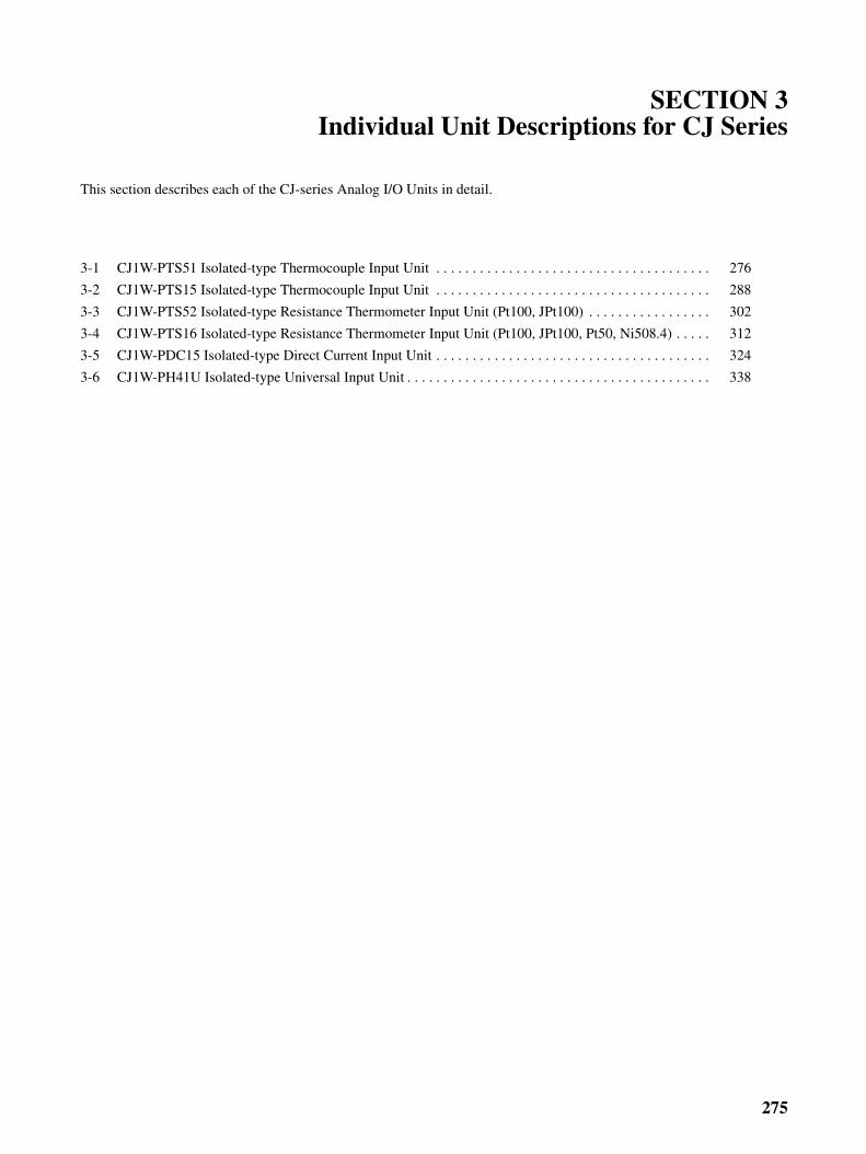
SECTION 3Individual Unit Descriptions for CJ Series
This section describes each of the CJ-series Analog I/O Units in detail.
3-1 CJ1W-PTS51 Isolated-type Thermocouple Input Unit . . . . . . . . . . . . . . . . . . . . . . . . . . . . . . . . . . . . . . 276
3-2 CJ1W-PTS15 Isolated-type Thermocouple Input Unit . . . . . . . . . . . . . . . . . . . . . . . . . . . . . . . . . . . . . . 288
3-3 CJ1W-PTS52 Isolated-type Resistance Thermometer Input Unit (Pt100, JPt100) . . . . . . . . . . . . . . . . . 302
3-4 CJ1W-PTS16 Isolated-type Resistance Thermometer Input Unit (Pt100, JPt100, Pt50, Ni508.4) . . . . . 312
3-5 CJ1W-PDC15 Isolated-type Direct Current Input Unit . . . . . . . . . . . . . . . . . . . . . . . . . . . . . . . . . . . . . . 324
3-6 CJ1W-PH41U Isolated-type Universal Input Unit . . . . . . . . . . . . . . . . . . . . . . . . . . . . . . . . . . . . . . . . . . 338
275

Section 3-1CJ1W-PTS51 Isolated-type Thermocouple Input Unit
3-1 CJ1W-PTS51 Isolated-type Thermocouple Input UnitOverview
The CJ1W-PTS51 Isolated-type Thermocouple Input Unit provides four directthermocouple inputs, and sends the data to the CPU Unit each cycle. Allinputs are isolated.
CJ1W-PTS51
System Configuration
Features• Up to four Thermocouples can be connected for each Unit. (The tempera-
ture sensor and input range settings are the same for all four inputs.)• There is isolation between channels, so unwanted circuit paths between
thermocouple inputs can be prevented.• A variety of temperature specifications are supported. Any of the following
can be selected for thermocouple input: K, J, L, R, S, T, B (Decimal pointscan be selected for K, J, and L.)
• Temperature sensor values are transmitted to the CPU Unit in four digitshexadecimal. (Binary or BCD can be selected for the data output format.)
• Process value alarm (with two internal alarms in memory and one exter-nal alarm output for each input)
• Alarm ON-delay timer and hysteresis for process value• Zero/span adjustment capability during operation• Sensor error detection• Maximum or minimum process value can be specified for when a sensor
error is detected.
PTS51
MACH
No.
X101
X100
RUNERCERH
ALM
12
34
--
-
CJ1W-PTS51
4 thermocouple inputs (K, J, L, R, S, T, B)
276
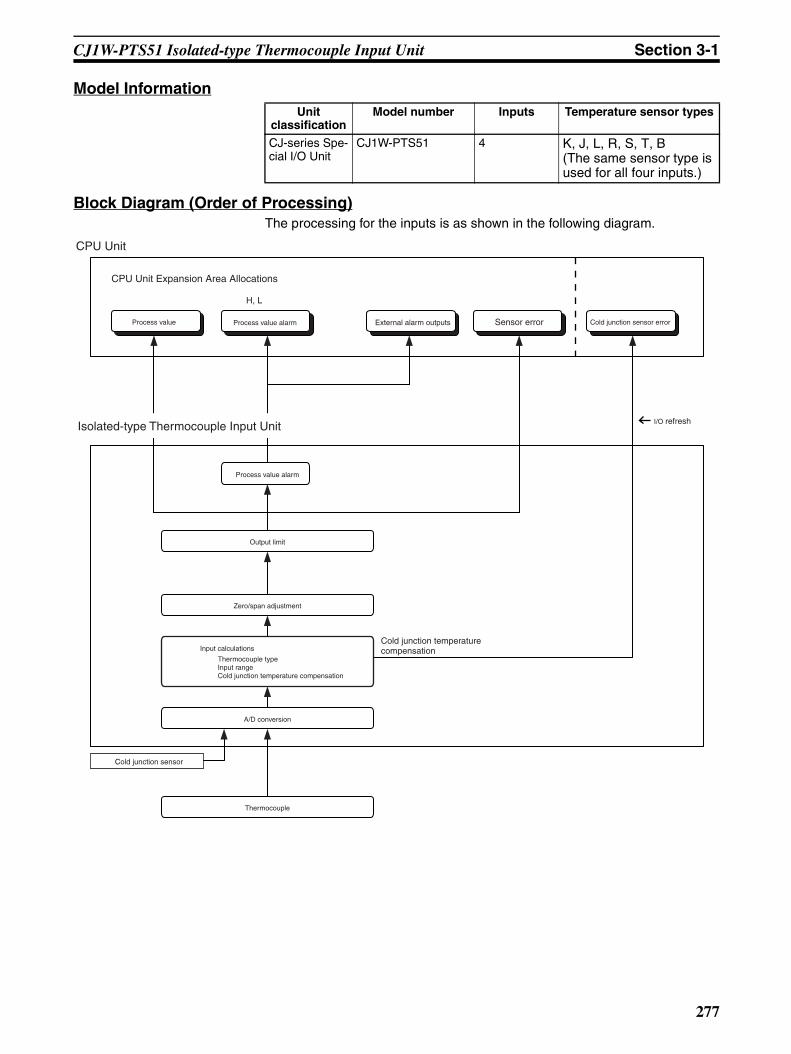
Section 3-1CJ1W-PTS51 Isolated-type Thermocouple Input Unit
Model Information
Block Diagram (Order of Processing)The processing for the inputs is as shown in the following diagram.
Unit classification
Model number Inputs Temperature sensor types
CJ-series Spe-cial I/O Unit
CJ1W-PTS51 4 K, J, L, R, S, T, B (The same sensor type is used for all four inputs.)
Output limit
Zero/span adjustment
Input calculations
Thermocouple typeInput rangeCold junction temperature compensation
A/D conversion
H, L
CPU Unit
I/O refresh
Process value Process value alarm Sensor error
CPU Unit Expansion Area Allocations
Isolated-type Thermocouple Input Unit
Process value alarm
Cold junction sensor error
Cold junction temperature compensation
Thermocouple
Cold junction sensor
External alarm outputs
277

Section 3-1CJ1W-PTS51 Isolated-type Thermocouple Input Unit
SpecificationsItem Specifications
Model CJ1W-PTS51
Applicable PLC CJ Series
Unit classification CJ-series Special I/O Unit
Mounting position CJ-series CPU Rack or CJ-series Expansion Rack
Maximum number of Units 40 (within the allowable current consumption and power consumption range)
Unit numbers 00 to 95 (Cannot duplicate Special I/O Unit numbers.)
Areas for data exchange with CPU Unit
Special I/O Unit Area
10 words/UnitThermocouple Input Unit to CPU Unit:All process values, process value alarms (L, H), conversion data enabled flag, sensor errors, cold junction sensor errors
DM Area words allocated to Special I/O Units
100 words/UnitCPU Unit to Thermocouple Input Unit:Temperature sensor type, input range (same for all I/O), process value alarm setting (L, H), zero/span adjustment value.
Number of temperature sensor inputs
4
Temperature sensor types Selectable from K, J, L, R, S, T, B. (Same setting for all inputs.)
Data storage in the CIO Area The actual process data in the input range is stored in four digits hexadecimal (binary or BCD values) in the allocated words in the CIO Area.
Accuracy (25°C) (See note.) With Celsius selected: ±0.3% of PV or ±1°C, whichever is greater, ±1 digit max.
With fahrenheit selected: ±0.3% of PV or ±2°F, whichever is greater, ±1 digit max.However, the accuracy of K and T at −100°C or lower and L is ±2°C ±1 digit max.The accuracy of R and S at 200°C or lower is ±3°C ±1 digit max.
The accuracy of B at 400°C or lower is not specified.PV: Process value data
Temperature characteristics Refer to Temperature Characteristics According to Thermocouple Type on page 280.
Warmup time 30 min
Conversion period 250 ms/4 inputs.
Maximum time to store data in CPU Unit
Conversion period + one CPU Unit cycle
Sensor error detection Detects sensor error at each input and turns ON the Sensor error Flag.Hardware detection time: Approx. 0.5 s max.The process value overrange direction for when a sensor error occurs can be speci-fied. (High: Set input range +20°C or +20°F; low: Set input range −20°C or −20°F)
Function Process value alarm
Process value 2-point alarm (HH, H, LL, L), alarm hysteresis, and ON-delay timer (0 to 60 s) are available. External alarm outputs: One per input (H or L).
External alarm outputs
NPN outputs (with short-circuit protection)
External power supply voltage: 20.4 to 26.4 V DCMax. switching capacity: 100 mA (for one output) Leakage current: 0.3 mA max.Residual voltage: 3 V max.
Isolation Between inputs and PLC signal: Transformer for power supply and photocoupler for signals
Between each input: Transformer for power supply and photocoupler for signals.
Insulation resistance 20 MΩ max. (at 500 V DC).
Between all output and NC terminals and external AC terminals (Power Supply Unit)Between all input terminals and external AC terminals (Power Supply Unit)Between all input terminals and all output terminals
Between all external DC terminals (input, output, and NC terminals) and FG plateBetween all input and output terminals and all NC terminals
278

Section 3-1CJ1W-PTS51 Isolated-type Thermocouple Input Unit
Sensor Type and Input RangeThe Temperature Sensor type and input range are set in the allocated wordsin the DM Area for every four inputs.
The measurable data range is ±20 digits wider than the sensor input range.
Dielectric strength Between all output and NC terminals and external AC terminals (Power Supply Unit)2,000 VAC, 50/60 Hz 1 min., detection current: 1 mA
Between all input terminals and external AC terminals (Power Supply Unit)Between all input terminals and all output terminalsBetween all external DC terminals (input, output, and NC terminals) and FG plate1,000 VAC, 50/60 Hz 1 min., detection current: 1 mABetween all channels500 VAC, 50/60 Hz 1 min., detection current: 1 mA
External connections Terminal block (detachable)
Unit number settings Set by rotary switches on front panel, from 0 to 95.
Indicators Seven LED indicators on front panel (for normal operation, errors detected at the Thermocouple Input Unit, errors related to the CPU Unit, and four indicators for exter-nal alarm outputs.)
Effect on CPU Unit cycle time 0.4 ms
Current consumption (supplied from Power Supply Unit)
5 V DC at 250 mA max.
Dimensions 31 × 90 × 65 mm (W × H × D)
Weight 150 g max.
Item Specifications
Set-ting
Input °C °F16-bit binary BCD 16-bit binary BCD
F@@@ indicates
minus sign.
Leftmost bit indicates
minus sign.
F@@@ indicates
minus sign.
Leftmost bit indicates
minus sign.
0 K: −200 to 1300°C(−300 to 2300°F)
FF38 to FFFF to 0514(−200 to −1 to 1300)
F200 to 1300(−200 to 1300)
8200 to 1300(−200 to 1300)
FED4 to FFFF to 08FC(−300 to −1 to 2300)
F300 to 2300(−300 to 2300)
F300 to 2300(−300 to 2300)
1 K: 0.0 to 500°C(0.0 to 900.0°F)
0000 to 1388(0.0 to 500.0)
0000 to 5000(0.0 to 500.0)
0000 to 5000(0.0 to 500.0)
0000 to 2328(0.0 to 900.0)
0000 to 9000(0.0 to 900.0)
0000 to 7999 (See note 3.)(0.0 to 799.9)
2 J: −100 to 850°C(−100 to 1500°F)
FF9C to FFFF to 0352(−100 to −1 to 850)
F100 to 0850(−100 to 850)
8100 to 0850(−100 to 850)
FF9C to FFFF to 05DC(−100 to −1 to 1500)
F100 to 1500(−100 to 1500)
8100 to 1500(−100 to 1500)
3 J: 0.0 to 400.0°C(0.0 to 750.0°F)
0000 to 0FA0(0.0 to 400.0)
0000 to 4000(0.0 to 400.0)
0000 to 4000(0.0 to 400.0)
0000 to 1D4C(0.0 to 750.0)
0000 to 7500(0.0 to 750.0)
0000 to 7500(0.0 to 750.0)
4 T: −200 to 400°C(−300 to 700.0°F)
F830 to FFFF to 0FA0(−200.0 to −0.1 to 400.0)
F999 to 4000 (See note 3.)(−99.9 to 400.0)
A000 to 4000(−200.0 to 400.0)
F448 to FFFF to 1B58(−300.0 to −0.1 to 700.0)
F999 to 7000 (See note 3.)(−99.9 to 700.0)
B000 to 7000(−300.0 to 700.0)
5 L: −100 to 850°C(−100 to 1500°F)
FF9C to FFFF to 0352(−100 to −1 to 850)
F100 to 0850(−100 to 850)
8100 to 0850(−100 to 850)
FF9C to FFFF to 05DC(−100 to −1 to 1500)
F100 to 1500(−100 to 1500)
8100 to 1500(−100 to 1500)
6 L: 0.0 to 400.0°C(0.0 to 750.0°F)
0000 to 0FA0(0.0 to 400.0)
0000 to 4000(0.0 to 400.0)
0000 to 4000(0.0 to 400.0)
0000 to 1D4C(0.0 to 750.0)
0000 to 7500(0.0 to 750.0)
0000 to 7500(0.0 to 750.0)
7 R: 0 to 1700°C(0 to 3000°F)
0000 to 06A4(0 to 1700)
0000 to 1700(0 to 1700)
0000 to 1700(0 to 1700)
0000 to 0BB8(0 to 3000)
0000 to 3000(0 to 3000)
0000 to 3000(0 to 3000)
279

Section 3-1CJ1W-PTS51 Isolated-type Thermocouple Input Unit
Note 1. If the indication range is exceeded, a sensor error will occur and the sensorerror bit will turn ON. The process value will be clamped at the lower or up-per limit of the indication range, depending on the setting for data directionat sensor error.
2. The lower limit for B thermocouples is 0°C/°F.
3. The indicator range for BCD display will be clamped at the lower (or upper)limit in the region between the lower (or upper) limit of the setting rangeand the point where a sensor error occurs.For 0.1°C/0.1°F indication with minus sign indicated by leftmost 4 bits (bits12 to 15): Lower limit = −99.9, Upper limit = 999.9.For 0.1°C/0.1°F indication with minus sign indicated by leftmost bit (bit 15):Lower limit = −799.9, Upper limit = 799.9.
Temperature Characteristics According to Thermocouple Type
The measured temperature error is calculated as shown in the followingexample.
8 S: 0 to 1700°C(0 to 3000°F)
0000 to 06A4(0 to 1700)
0000 to 1700(0 to 1700)
0000 to 1700(0 to 1700)
0000 to 0BB8(0 to 3000)
0000 to 3000(0 to 3000)
0000 to 3000(0 to 3000)
9 B: 400 to 1800°C (See note 2.)(750 to 3200°F)
0190 to 0708(400 to 1800)
0400 to 1800(400 to 1800)
0400 to 1800(400 to 1800)
02EE to 0C80(750 to 3200)
0750 to 3200(750 to 3200)
0750 to 3200(750 to 3200)
Set-ting
Input °C °F16-bit binary BCD 16-bit binary BCD
F@@@ indicates
minus sign.
Leftmost bit indicates
minus sign.
F@@@ indicates
minus sign.
Leftmost bit indicates
minus sign.
Thermocouple Temperature range Set value error when ambient temperature changes by 1°C
R 0 to 200 °C ±0.43°C200 to 1,000°C ±0.29°C1,000 to 1,700°C ±285 ppm of PV
S 0 to 200 °C ±0.43°C200 to 1,000°C ±0.29°C1,000 to 1,700°C 285 ppm of PV
B 400°C or less Not specified.
400 to 800°C ±0.43°C800 to 1,000°C ±0.29°C1,000 to 1,800°C 285 ppm of PV
K −200 to −100°C ±0.29°C−100 to 400°C ±0.11°C400 to 1,300°C ±285 ppm of PV
J −100 to 400°C ±0.11°C400 to 850°C ±285 ppm of PV
T −200 to −100°C ±0.29°C−100 to 400°C ±0.11°C
L −100 to 400°C ±0.11°C400 to 850°C ±285 ppm of PV
Item Details
Ambient temperature 30°CThermocouple type K
Measured temperature (PV) 500°C
280
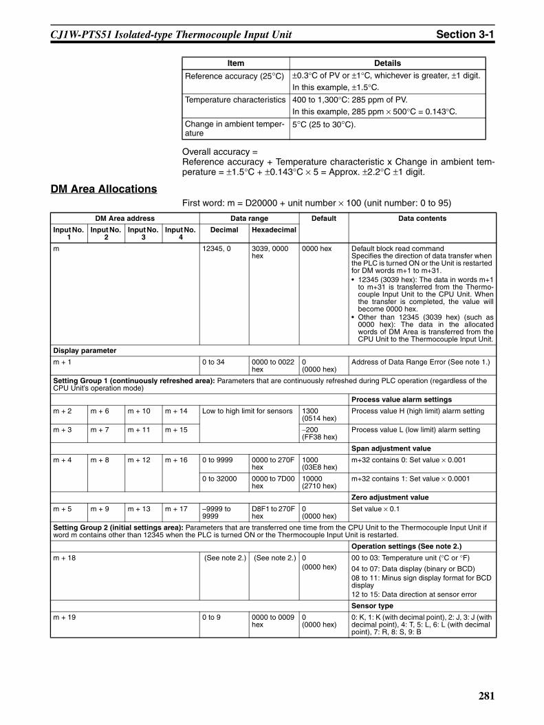
Section 3-1CJ1W-PTS51 Isolated-type Thermocouple Input Unit
Overall accuracy = Reference accuracy + Temperature characteristic x Change in ambient tem-perature = ±1.5°C + ±0.143°C × 5 = Approx. ±2.2°C ±1 digit.
DM Area AllocationsFirst word: m = D20000 + unit number × 100 (unit number: 0 to 95)
Reference accuracy (25°C) ±0.3°C of PV or ±1°C, whichever is greater, ±1 digit.In this example, ±1.5°C.
Temperature characteristics 400 to 1,300°C: 285 ppm of PV.In this example, 285 ppm × 500°C = 0.143°C.
Change in ambient temper-ature
5°C (25 to 30°C).
Item Details
DM Area address Data range Default Data contents
Input No. 1
Input No. 2
Input No. 3
Input No. 4
Decimal Hexadecimal
m 12345, 0 3039, 0000 hex
0000 hex Default block read commandSpecifies the direction of data transfer when the PLC is turned ON or the Unit is restarted for DM words m+1 to m+31.• 12345 (3039 hex): The data in words m+1
to m+31 is transferred from the Thermo-couple Input Unit to the CPU Unit. Whenthe transfer is completed, the value willbecome 0000 hex.
• Other than 12345 (3039 hex) (such as0000 hex): The data in the allocatedwords of DM Area is transferred from theCPU Unit to the Thermocouple Input Unit.
Display parameter
m + 1 0 to 34 0000 to 0022 hex
0 (0000 hex)
Address of Data Range Error (See note 1.)
Setting Group 1 (continuously refreshed area): Parameters that are continuously refreshed during PLC operation (regardless of the CPU Unit’s operation mode)
Process value alarm settings
m + 2 m + 6 m + 10 m + 14 Low to high limit for sensors 1300 (0514 hex)
Process value H (high limit) alarm setting
m + 3 m + 7 m + 11 m + 15 −200 (FF38 hex)
Process value L (low limit) alarm setting
Span adjustment value
m + 4 m + 8 m + 12 m + 16 0 to 9999 0000 to 270F hex
1000(03E8 hex)
m+32 contains 0: Set value × 0.001
0 to 32000 0000 to 7D00 hex
10000 (2710 hex)
m+32 contains 1: Set value × 0.0001
Zero adjustment value
m + 5 m + 9 m + 13 m + 17 –9999 to 9999
D8F1 to 270F hex
0 (0000 hex)
Set value × 0.1
Setting Group 2 (initial settings area): Parameters that are transferred one time from the CPU Unit to the Thermocouple Input Unit if word m contains other than 12345 when the PLC is turned ON or the Thermocouple Input Unit is restarted.
Operation settings (See note 2.)
m + 18 (See note 2.) (See note 2.) 0(0000 hex)
00 to 03: Temperature unit (°C or °F)
04 to 07: Data display (binary or BCD)08 to 11: Minus sign display format for BCD display12 to 15: Data direction at sensor error
Sensor type
m + 19 0 to 9 0000 to 0009 hex
0 (0000 hex)
0: K, 1: K (with decimal point), 2: J, 3: J (with decimal point), 4: T, 5: L, 6: L (with decimal point), 7: R, 8: S, 9: B
281
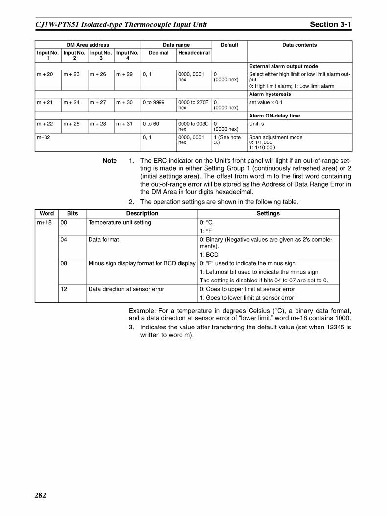
Section 3-1CJ1W-PTS51 Isolated-type Thermocouple Input Unit
Note 1. The ERC indicator on the Unit's front panel will light if an out-of-range set-ting is made in either Setting Group 1 (continuously refreshed area) or 2(initial settings area). The offset from word m to the first word containingthe out-of-range error will be stored as the Address of Data Range Error inthe DM Area in four digits hexadecimal.
2. The operation settings are shown in the following table.
Example: For a temperature in degrees Celsius (°C), a binary data format,and a data direction at sensor error of “lower limit,” word m+18 contains 1000.3. Indicates the value after transferring the default value (set when 12345 is
written to word m).
External alarm output mode
m + 20 m + 23 m + 26 m + 29 0, 1 0000, 0001 hex
0 (0000 hex)
Select either high limit or low limit alarm out-put.0: High limit alarm; 1: Low limit alarm
Alarm hysteresis
m + 21 m + 24 m + 27 m + 30 0 to 9999 0000 to 270F hex
0 (0000 hex)
set value × 0.1
Alarm ON-delay time
m + 22 m + 25 m + 28 m + 31 0 to 60 0000 to 003C hex
0 (0000 hex)
Unit: s
m+32 0, 1 0000, 0001 hex
1 (See note 3.)
Span adjustment mode0: 1/1,0001: 1/10,000
DM Area address Data range Default Data contents
Input No. 1
Input No. 2
Input No. 3
Input No. 4
Decimal Hexadecimal
Word Bits Description Settings
m+18 00 Temperature unit setting 0: °C1: °F
04 Data format 0: Binary (Negative values are given as 2’s comple-ments).1: BCD
08 Minus sign display format for BCD display 0: “F” used to indicate the minus sign.1: Leftmost bit used to indicate the minus sign.
The setting is disabled if bits 04 to 07 are set to 0.
12 Data direction at sensor error 0: Goes to upper limit at sensor error
1: Goes to lower limit at sensor error
282

Section 3-1CJ1W-PTS51 Isolated-type Thermocouple Input Unit
CIO Area AllocationsFirst word: n = 2000 + unit number × 10 (unit number: 0 to 95)
Note The Conversion Data Enabled Flag remains OFF after the PLC is turned ONor the Unit is restarted until the AD conversion data becomes stable (approxi-mately 2 to 4 s), then is ON during operation.
Direction Word Bit Name Data range Contents
Thermocouple Input Unit to CPU Unit
n 00 Input No. 1 Process value L (low limit) alarm
0, 1 0: Process value > Set value1: Process value ≤ Set value
01 Process value H (high limit) alarm
0, 1 0: Process value < Set value1: Process value ≥ Set value
02 Input No. 2 Process value L (low limit) alarm
0, 1 Same as for input No. 1.
03 Process value H (high limit) alarm
0, 1
04 Input No. 3 Process value L (low limit) alarm
0, 1
05 Process value H (high limit) alarm
0, 1
06 Input No. 4 Process value L (low limit) alarm
0, 1
07 Process value H (high limit) alarm
0, 1
08 to 15 Not used.
n + 1 00 to 15 Input No. 1 Process value Depends on type of input.
Stores data in the data range specified for each input type ±20 digits.
n + 2 00 to 15 Input No. 2
n + 3 00 to 15 Input No. 3
n + 4 00 to 15 Input No. 4
Thermocouple Input Unit to CPU Unit
n + 5 00 to 15 Not used.
n + 6 00 to 15
n + 7 00 to 15
n + 8 00 to 15
n + 9 00 Input No. 1 Sensor error 0, 1 0: Normal1: Error01 Input No. 2 0, 1
02 Input No. 3 0, 1
03 Input No. 4 0, 1
04 to 07 Not used.
08 Cold junction sensor error 0, 1 0: Normal1: Error
09 to 14 Not used.
15 Conversion data enabled flag (See note.)
0, 1 0: Data disabled1: Data enabled
283

Section 3-1CJ1W-PTS51 Isolated-type Thermocouple Input Unit
Terminal Connection Diagram
Note Action for Unused Input Terminals
• Short-circuit the positive (+) and negative (−) sides of the thermocoupleinput section using a lead wire. For example, short terminals A3 and A2for No. 1 thermocouple input.
• Cold junction sensors are mounted before shipment. If one of the coldjunction sensors is disconnected, cold junction compensation will stopand correct measurement of temperatures cannot be made. Always makesure the cold junction sensors are connected when using the Units.
• Cold junction sensors are calibrated separately for each Unit and con-nected circuit, so correct temperatures will not be measured if a cold junc-tion sensor from another Unit is used or if the two cold junction sensors ina Unit are swapped. Use the cold junction sensors as they are provided,without making any changes.
• Do not connect anything to NC terminals. Do not use NC terminals asrelay terminals.
• Always ground the GR terminal on the Power Supply Unit of the PLC.• If the input device uses a voltage generator, temperature compensator, or
similar device, then ground the input device if it has a ground terminal.
External alarm outputs
2−2+
CJ
CJ
4−4+
ALM2
ALM4
0V
B1
B2
B3
B4
B5
B6
B7
B8
B9
A1
A2
A3
A4
A5
A6
A7
A8
A9
1−1+
N.C.
N.C.
3−3+
ALM1
ALM3
24V
No. 2 thermocouple input
Cold junction sensors
No. 4 thermocouple input
No. 1 thermocouple input
No. 3 thermocouple input
External alarm outputsL
L
L
L
284
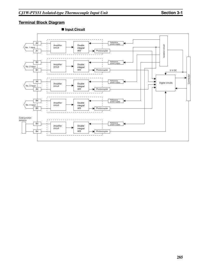
Section 3-1CJ1W-PTS51 Isolated-type Thermocouple Input Unit
Con
nect
or
Terminal Block Diagram
Input Circuit
5 V DC
No. 1 inputAmplifier circuit
Photocoupler
A2
A1
No. 2 inputAmplifier circuit
Photocoupler
B2
B1
No. 3 inputAmplifier circuit
Photocoupler
A6
A5
No. 4 inputAmplifier circuit
Photocoupler
B6
B5
Cold junction sensors
Amplifier circuit
Photocoupler
B3
B4
Isol
atio
n ci
rcui
t
Digital circuits
Double integral A/D
Reference power supply
Double integral A/D
Double integral A/D
Double integral A/D
Double integral A/D
Reference power supply
Reference power supply
Reference power supply
Reference power supply
285

Section 3-1CJ1W-PTS51 Isolated-type Thermocouple Input Unit
Output Circuit
Error Processing
Conversion Data Does Not Change.
Values are Not Converted as Intended.
Inte
rnal
Circ
uit
L
L
L
L
Output DisplayLED
B7ALM2
A8ALM3
B8ALM4
B90V
A924V
A7ALM1
Probable cause Remedy
The gain for span adjustment is set to 0.
Set the gain for span adjustment to a value other than 0.
The sensor type is not set cor-rectly.
Check and correct the settings.
An input device is malfunctioning, input wiring is faulty, or wiring is disconnected.
Check whether the input voltage or current has changed. Check for faulty or disconnected wir-ing. Check whether a sensor error has been detected in the I/O Area.
Probable cause Remedy
The sensor type is not set cor-rectly.
Check and correct the settings.
The zero/span adjustment data is incorrect.
Check and correct the zero/span adjustment set-tings.
286

Section 3-1CJ1W-PTS51 Isolated-type Thermocouple Input Unit
Converted Values are Unstable.
Cold junction compensation is not operating.
Check the Cold Junction Error Flag.
A compensation conductor has not been used or a different com-pensation conductor is used.
Use the correct compensation conductor for the thermocouple.
Incorrect input wiring (incorrect thermocouple or compensation conductor polarity.)
Correct the input wiring.
Thermocouple lead or compensat-ing conductor is too long and mea-surements are being affected by conductor resistance.
Use a thicker compensating conductor.
Change the wiring position and shorten the com-pensating conductor.
The terminal block temperature is not uniform due to radiated heat from peripheral devices.
Mount the unit in a position unaffected by radi-ated heat.
Probable cause Remedy
Input signals are being affected by external noise.
Change the connection paths of the input signal lines. (Separate them from sources of noise or use shielded cable.)
Insert a 0.01 to 0.1 µF ceramic capacitor between the positive (+) and negative (−) input terminals.
An airflow is hitting the Unit termi-nal block.
Move the terminal block to a position unaffected by airflow.
Probable cause Remedy
287
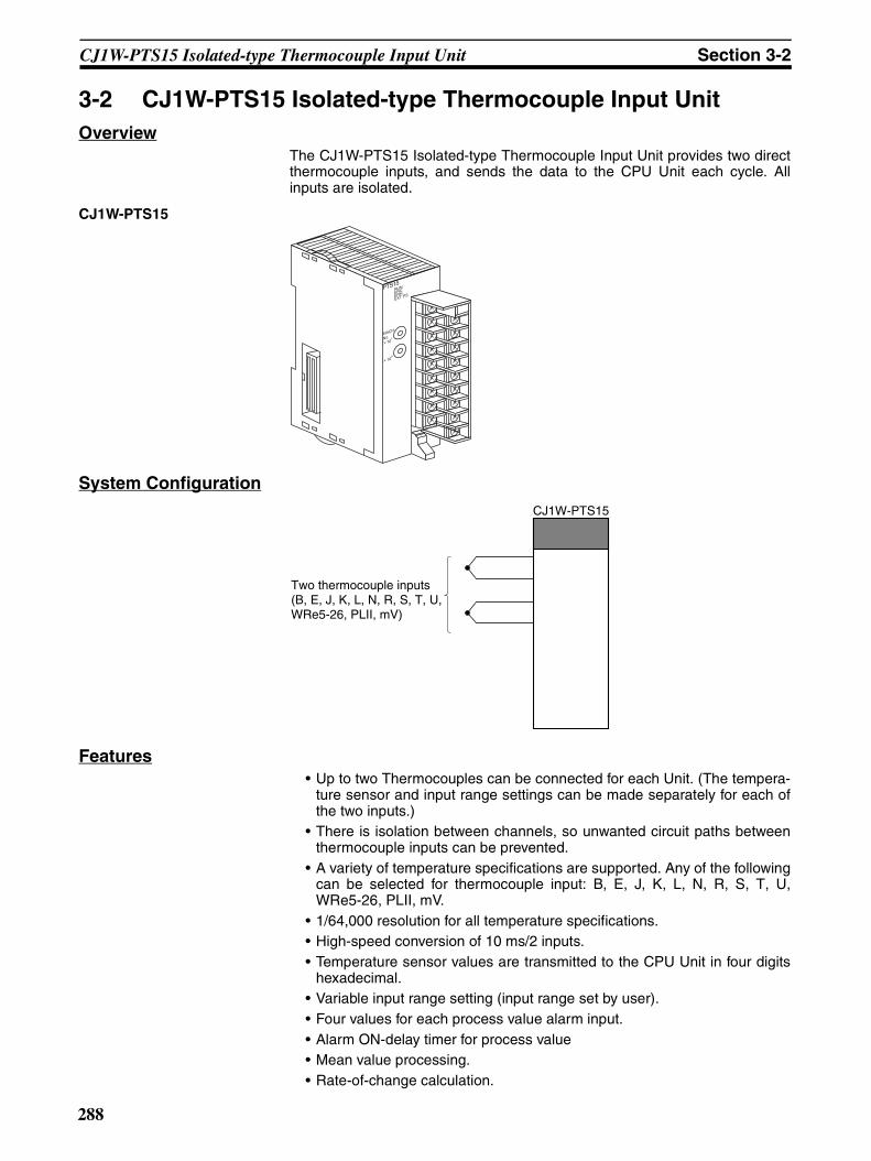
Section 3-2CJ1W-PTS15 Isolated-type Thermocouple Input Unit
3-2 CJ1W-PTS15 Isolated-type Thermocouple Input UnitOverview
The CJ1W-PTS15 Isolated-type Thermocouple Input Unit provides two directthermocouple inputs, and sends the data to the CPU Unit each cycle. Allinputs are isolated.
CJ1W-PTS15
System Configuration
Features• Up to two Thermocouples can be connected for each Unit. (The tempera-
ture sensor and input range settings can be made separately for each ofthe two inputs.)
• There is isolation between channels, so unwanted circuit paths betweenthermocouple inputs can be prevented.
• A variety of temperature specifications are supported. Any of the followingcan be selected for thermocouple input: B, E, J, K, L, N, R, S, T, U,WRe5-26, PLII, mV.
• 1/64,000 resolution for all temperature specifications.• High-speed conversion of 10 ms/2 inputs.• Temperature sensor values are transmitted to the CPU Unit in four digits
hexadecimal.• Variable input range setting (input range set by user).• Four values for each process value alarm input.• Alarm ON-delay timer for process value• Mean value processing.• Rate-of-change calculation.
PTS15
MACH
No. 1
0
RUNERCERHEXT PS
CJ1W-PTS15
Two thermocouple inputs(B, E, J, K, L, N, R, S, T, U, WRe5-26, PLII, mV)
288
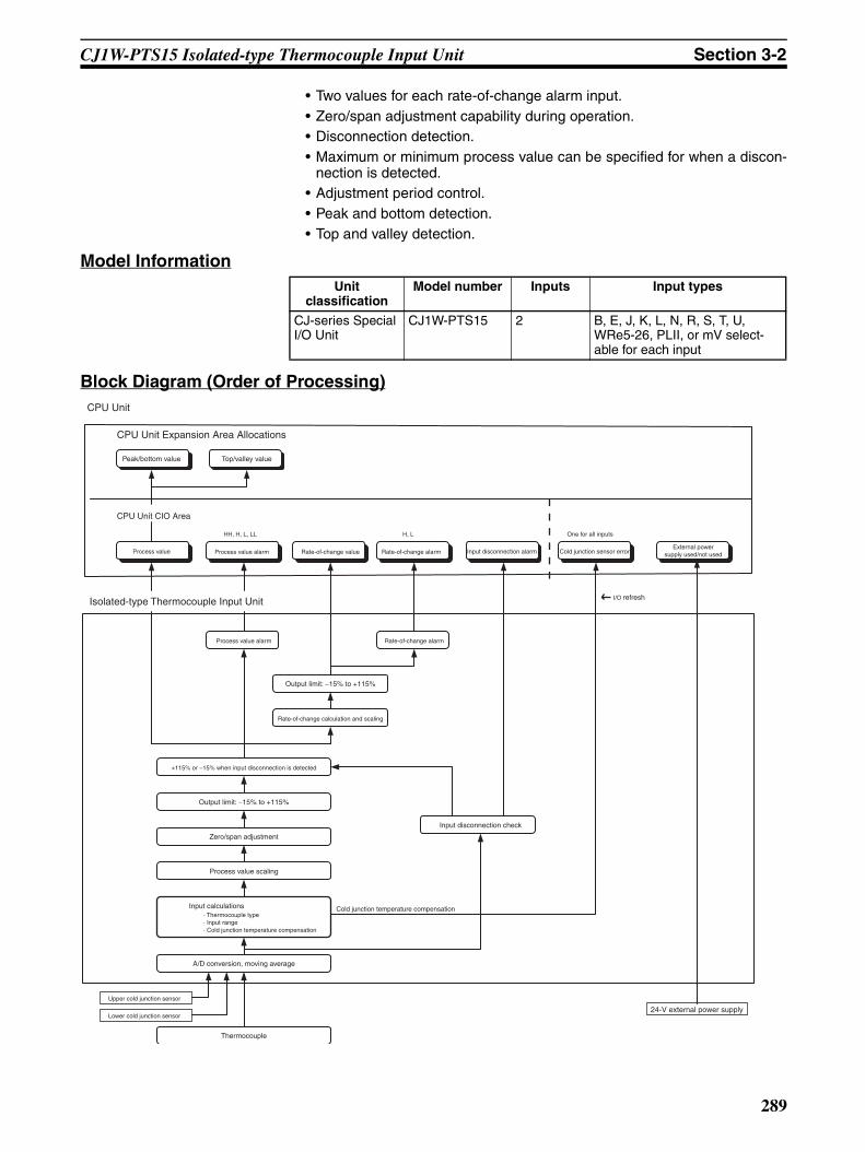
Section 3-2CJ1W-PTS15 Isolated-type Thermocouple Input Unit
• Two values for each rate-of-change alarm input.• Zero/span adjustment capability during operation.• Disconnection detection.• Maximum or minimum process value can be specified for when a discon-
nection is detected.• Adjustment period control.• Peak and bottom detection.• Top and valley detection.
Model Information
Block Diagram (Order of Processing)
Unit classification
Model number Inputs Input types
CJ-series Special I/O Unit
CJ1W-PTS15 2 B, E, J, K, L, N, R, S, T, U, WRe5-26, PLII, or mV select-able for each input
Rate-of-change alarm
Output limit: −15% to +115%
Rate-of-change calculation and scaling
+115% or −15% when input disconnection is detected
Output limit: −15% to +115%
Zero/span adjustment
Process value scaling
Input calculations· Thermocouple type · Input range· Cold junction temperature compensation
A/D conversion, moving average
Input disconnection check
HH, H, L, LL H, L
Top/valley value
CPU Unit
CPU Unit Expansion Area Allocations
I/O refresh
Peak/bottom value
Process value Process value alarm Rate-of-change value Rate-of-change alarm Input disconnection alarm
CPU Unit CIO Area
Isolated-type Thermocouple Input Unit
Process value alarm
Cold junction sensor error
One for all inputs
Cold junction temperature compensation
Thermocouple
Upper cold junction sensor
Lower cold junction sensor
External power supply used/not used
24-V external power supply
289

Section 3-2CJ1W-PTS15 Isolated-type Thermocouple Input Unit
SpecificationsItem Specifications
Model CJ1W-PTS15
Applicable PLC CJ Series
Unit classification CJ-series Special I/O Unit
Mounting position CJ-series CPU Rack or CJ-series Expansion Rack
Maximum number of Units 40 (within the allowable current consumption and power consumption range)
Unit numbers 00 to 95 (Cannot duplicate Special I/O Unit numbers.)
Areas for data exchange with CPU Unit
Special I/O Unit Area
10 words/UnitThermocouple Input Unit to CPU Unit:All process values, process value alarms (LL, L, H, HH), conversion data enabled flags, sensor errors.
DM Area words allocated to Special I/O Units
100 words/UnitCPU Unit to Thermocouple Input Unit:Temperature sensor type, input range (user set), process value alarm setting (L, H), zero/span adjustment value.
Expansion Con-trol/Monitor Area words
35 words/UnitCPU Unit to Thermocouple Input Unit:Hold function selection start/reset, adjustment period control, control bitsThermocouple Input Unit to CPU Unit:Adjustment period warnings/notices (for each input), peak and bottom values, top and valley values
Expansion Set-ting Area words
46 words/Unit
CPU Unit to Thermocouple Input Unit:Expansion Setting Area settings, adjustment period control, peak and bottom detec-tion, top and valley detection
Number of temperature sensor inputs
2
Temperature sensor type The sensor type, input range, and scaling can be set individually for each of 2 inputs, which are each selectable from B, E, J, K, L, N, R, S, T, U, WRe5-26, PL II, and mV.
Scaling Data to be stored in the allocated words in the CIO area must be scaled (with the min-imum and maximum values set by user) (2 inputs set separately). For example, data can be stored at 0% to 100%.
Data storage in the CIO Area The value derived from carrying out the following processing in order of the actual pro-cess data in the input range is stored in four digits hexadecimal (binary values) in the allocated words in the CIO Area.1) Mean value processing → 2) Scaling → 3) Zero/span adjustment → 4) Output limits
Accuracy (25°C) ±0.05% (Depends on the Sensor used and the measured temperature. Refer to Accu-racy by Sensor Type and Measured Temperature Range on page 292 for details.)
Temperature coefficient ±0.01%/°C (For full scale of electromotive force. See note.)
Resolution 1/64000
Cold junction compensation error ±1°C, at 20 ±10°CMaximum signal input ±120 mV
Input impedance 20 kΩ min.
Input disconnection detection cur-rent
0.1 µA (typical)
Warmup time 45 min
Response time 100 ms (travel time from input 0% to 90%, for ±100 mV step input and with moving average for 4 samples)
Conversion period 10 ms/2 inputs
Maximum time to store data in CPU Unit
Conversion period + one CPU Unit cycle
Disconnection detection Detects disconnections at each input and turns ON the Disconnection Detection Flag.Hardware detection time: Approx. 0.5 s max.The process value overrange direction for when a disconnection occurs can be speci-fied. (High: 115% of set input range; low: –15% of set input range)
290

Section 3-2CJ1W-PTS15 Isolated-type Thermocouple Input Unit
Note The method for calculating the error in temperature measurements, includingthe temperature coefficient, is given below. The “full scale of electromotiveforce” is the difference between the high limit and low limit converted to elec-tromotive force for each thermocouple.
ExampleAmbient temperature: 30 °CTemperature Sensor: K thermocouple (−270 to 1,372 °C)Measured temperature: 500 °C
From electromotive force table−270 °C: −6.458 mV1,372 °C: 54.86 mV
Full scale: 61.344
Function Mean value pro-cessing (input filter)
Calculates the moving average for the specified number of process values (1 to 128), and stores that value in the CIO Area as the process value.
Process value alarm
Process value 4-point alarm (LL, L, H, HH), alarm hysteresis, and ON-delay timer (0 to 60 s) are available.
Rate-of-change calculation
Calculates the amount of change per comparison time interval (1 to 16 s).
Rate-of-change alarm
Rate-of-change 2-point alarm (L, H), alarm hysteresis (shared with process value alarm), and ON-delay timer (0 to 60 s, shared with process value alarm) are available.
Adjustment period control
When zero/span adjustment is executed, the date is internally recorded at the Unit. When the preset zero/span adjustment period and number of days notice have elapsed (allocated in Expansion Setting Area), this function turns ON a warning flag to give notice that it is time for readjustment.
Peak and bot-tom detection
This function detects the maximum (peak) and minimum (bottom) analog input values, from when the Hold Start Bit (output) allocated to the Expansion Control/Monitor Area turns ON until it turns OFF, and stores them in the Expansion Control/Monitor Area.
Top and valley detection
This function detects the top and valley values for analog inputs, from when the Hold Start Bit (output) allocated to the Expansion Control/Monitor Area turns ON until it turns OFF, and stores them in the Expansion Control/Monitor Area.
Isolation Between inputs and PLC signals, and between inputs: Isolation by transformer for power supply, and by photocoupler for signals.Cold junction compensation circuit: No isolation from input 2
Insulation resistance 20 MΩ (at 500 V DC) between inputs
Dielectric strength Between inputs: 1,000 V AC, at 50/60 Hz, for 1 min, leakage current 10 mA max.
External connections Terminal block (detachable)
Unit number settings Set by rotary switches on front panel, from 0 to 95.
Indicators Four LED indicators on front panel (for normal operation, errors detected at the Ther-mocouple Input Unit, errors related to the CPU Unit, and use of external power sup-ply).
Front panel connector Sensor input connector terminal block (detachable)
Effect on CPU Unit cycle time 0.3 ms
Current consumption 5 V DC at 180 mA max.
External power supply 24 VDC +10%/−15% 60 mA max., inrush current: 20 A for 1 ms max.(The external 24-VDC power supply must be isolated.)
Dimensions 31 × 90 × 65 mm (W × H × D)
Weight 150 g max.
Standard accessories Two cold junction sensors (installed in terminal block)
Item Specifications
291
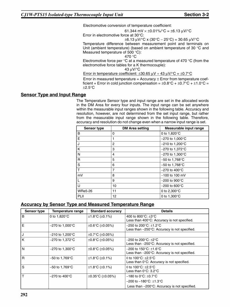
Section 3-2CJ1W-PTS15 Isolated-type Thermocouple Input Unit
Electromotive conversion of temperature coefficient:61.344 mV × ±0.01%/°C = ±6.13 µV/°C
Error in electromotive force at 30°C: ±6.13 µV/°C x (30°C − 25°C) = 30.65 µV/°C
Temperature difference between measurement point and terminals onUnit (ambient temperature) (based on ambient temperature of 30 °C andMeasured temperature of 500 °C):
470 °CElectromotive force per °C at a measured temperature of 470 °C (from theelectromotive force tables for a K thermocouple):
43 µV/°CError in temperature coefficient: ±30.65 µV ÷ 43 µV/°C = ±0.7°CError in measured temperature = Accuracy ± Error from temperature coef-ficient + Error in cold junction compensation = ±0.8°C + ±0.7°C + ±1.0°C =±2.5°C
Sensor Type and Input RangeThe Temperature Sensor type and input range are set in the allocated wordsin the DM Area for every four inputs. The input range can be set anywherewithin the measurable input ranges shown in the following table. Accuracy andresolution, however, are not determined from the set input range, but ratherfrom the measurable input range shown in the following table. Therefore,accuracy and resolution do not change even when a narrow input range is set.
Accuracy by Sensor Type and Measured Temperature Range
Sensor type DM Area setting Measurable input range
B 0 0 to 1,820°CE 1 −270 to 1,000°CJ 2 −210 to 1,200°CK 3 −270 to 1,372°CN 4 −270 to 1,300°CR 5 −50 to 1,768°CS 6 −50 to 1,768°CT 7 −270 to 400°CmV 8 −100 to 100 mV
L 9 −200 to 900°CU 10 −200 to 600°CWRe5-26 11 0 to 2,300°CPLII 12 0 to 1,300°C
Sensor type Temperature range Standard accuracy Details
B 0 to 1,820°C ±1.8°C (±0.1%) 400 to 800°C: ±3°CLess than 400°C: Accuracy is not specified.
E −270 to 1,000°C ±0.6°C (±0.05%) −250 to 200°C: ±1.2°CLess than −250°C: Accuracy is not specified.
J −210 to 1,200°C ±0.7°C (±0.05%)
K −270 to 1,372°C ±0.8°C (±0.05%) −250 to 200°C: ±2°CLess than −250°C: Accuracy is not specified.
N −270 to 1,300°C ±0.8°C (±0.05%) −200 to 150°C: ±1.6°CLess than −200°C: Accuracy is not specified.
R −50 to 1,769°C ±1.8°C (±0.1%) 0 to 100°C: ±2.5°CLess than 0°C: Accuracy is not specified.
S −50 to 1,769°C ±1.8°C (±0.1%) 0 to 100°C: ±2.5°CLess than 0°C: 3.2°C
T −270 to 400°C ±0.35°C (±0.05%) −180 to 0°C: ±0.7°C−200 to −180°C: ±1.3°C Less than −200°C: Accuracy is not specified.
292
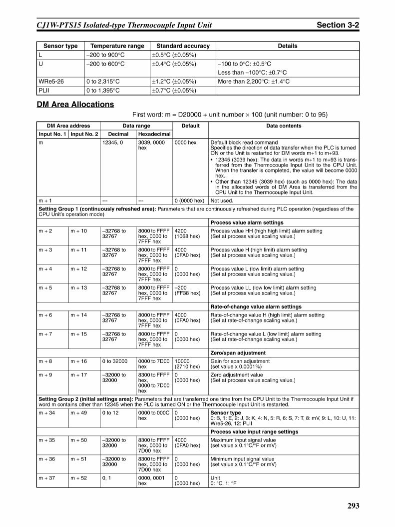
Section 3-2CJ1W-PTS15 Isolated-type Thermocouple Input Unit
DM Area AllocationsFirst word: m = D20000 + unit number × 100 (unit number: 0 to 95)
L −200 to 900°C ±0.5°C (±0.05%)
U −200 to 600°C ±0.4°C (±0.05%) −100 to 0°C: ±0.5°CLess than −100°C: ±0.7°C
WRe5-26 0 to 2,315°C ±1.2°C (±0.05%) More than 2,200°C: ±1.4°CPLII 0 to 1,395°C ±0.7°C (±0.05%)
Sensor type Temperature range Standard accuracy Details
DM Area address Data range Default Data contents
Input No. 1 Input No. 2 Decimal Hexadecimal
m 12345, 0 3039, 0000 hex
0000 hex Default block read commandSpecifies the direction of data transfer when the PLC is turned ON or the Unit is restarted for DM words m+1 to m+93.• 12345 (3039 hex): The data in words m+1 to m+93 is trans-
ferred from the Thermocouple Input Unit to the CPU Unit.When the transfer is completed, the value will become 0000hex.
• Other than 12345 (3039 hex) (such as 0000 hex): The datain the allocated words of DM Area is transferred from theCPU Unit to the Thermocouple Input Unit.
m + 1 --- --- 0 (0000 hex) Not used.
Setting Group 1 (continuously refreshed area): Parameters that are continuously refreshed during PLC operation (regardless of the CPU Unit’s operation mode)
Process value alarm settings
m + 2 m + 10 –32768 to 32767
8000 to FFFF hex, 0000 to 7FFF hex
4200 (1068 hex)
Process value HH (high high limit) alarm setting(Set at process value scaling value.)
m + 3 m + 11 –32768 to 32767
8000 to FFFF hex, 0000 to 7FFF hex
4000 (0FA0 hex)
Process value H (high limit) alarm setting(Set at process value scaling value.)
m + 4 m + 12 –32768 to 32767
8000 to FFFF hex, 0000 to 7FFF hex
0 (0000 hex)
Process value L (low limit) alarm setting(Set at process value scaling value.)
m + 5 m + 13 –32768 to 32767
8000 to FFFF hex, 0000 to 7FFF hex
–200 (FF38 hex)
Process value LL (low low limit) alarm setting(Set at process value scaling value.)
Rate-of-change value alarm settings
m + 6 m + 14 –32768 to 32767
8000 to FFFF hex, 0000 to 7FFF hex
4000 (0FA0 hex)
Rate-of-change value H (high limit) alarm setting(Set at rate-of-change scaling value.)
m + 7 m + 15 –32768 to 32767
8000 to FFFF hex, 0000 to 7FFF hex
0 (0000 hex)
Rate-of-change value L (low limit) alarm setting(Set at rate-of-change scaling value.)
Zero/span adjustment
m + 8 m + 16 0 to 32000 0000 to 7D00 hex
10000 (2710 hex)
Gain for span adjustment(set value x 0.0001%)
m + 9 m + 17 –32000 to 32000
8300 to FFFF hex,0000 to 7D00 hex
0 (0000 hex)
Zero adjustment value(Set at process value scaling value.)
Setting Group 2 (initial settings area): Parameters that are transferred one time from the CPU Unit to the Thermocouple Input Unit if word m contains other than 12345 when the PLC is turned ON or the Thermocouple Input Unit is restarted.
m + 34 m + 49 0 to 12 0000 to 000C hex
0 (0000 hex)
Sensor type0: B, 1: E, 2: J, 3: K, 4: N, 5: R, 6: S, 7: T, 8: mV, 9: L, 10: U, 11: Wre5-26, 12: PLII
Process value input range settings
m + 35 m + 50 –32000 to 32000
8300 to FFFF hex, 0000 to 7D00 hex
4000 (0FA0 hex)
Maximum input signal value(set value x 0.1°C/°F or mV)
m + 36 m + 51 –32000 to 32000
8300 to FFFF hex, 0000 to 7D00 hex
0 (0000 hex)
Minimum input signal value(set value x 0.1°C/°F or mV)
m + 37 m + 52 0, 1 0000, 0001 hex
0 (0000 hex)
Unit0: °C, 1: °F
293
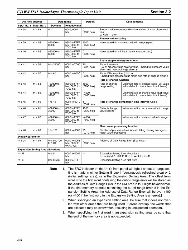
Section 3-2CJ1W-PTS15 Isolated-type Thermocouple Input Unit
Note 1. The ERC indicator on the Unit’s front panel will light if an out-of-range set-ting is made in either Setting Group 1 (continuously refreshed area) or 2(initial settings area), or in the Expansion Setting Area. The offset fromword m to the first word containing the out-of-range error will be stored asthe Address of Data Range Error in the DM Area in four digits hexadecimal.If the first memory address containing the out-of-range error is in the Ex-pansion Setting Area, the Address of Data Range Error will be over +100(or +100 if the first word in the Expansion Setting Area is an error).]
2. When specifying an expansion setting area, be sure that it does not over-lap with other areas that are being used. If areas overlap, the words thatare allocated may be overwritten, resulting in unexpected operation.
3. When specifying the first word in an expansion setting area, be sure thatthe end of the memory area is not exceeded.
m + 38 m + 53 0, 1 0000, 0001 hex
0 (0000 hex)
Process value overrange direction at time of input disconnec-tion0: High; 1: Low
Process value scaling
m + 39 m + 54 –32000 to 32000
8300 to FFFF hex, 0000 to 7D00 hex
4000 (0FA0 hex)
Value stored for maximum value in range (span)
m + 40 m + 55 –32000 to 32000
8300 to FFFF hex, 0000 to 7D00 hex
0 (0000 hex)
Value stored for minimum value in range (zero)
Alarm supplementary functions
m + 41 m + 56 0 to 32000 0000 to 7D00 hex
40 (0028 hex)
Alarm hysteresis(Set at process value scaling value. Shared with process value alarm and rate-of-change alarm.)
m + 42 m + 57 0 to 60 0000 to 003C hex
0 (0000 hex)
Alarm ON-delay time (Unit: s)(Shared with process value alarm and rate-of-change alarm.)
Rate-of-change function
m + 43 m + 58 –32000 to 32000
8300 to FFFF hex, 0000 to 7D00 hex
4000 (0FA0 hex)
Rate-of-change range setting
Maximum rate-of-change value (Set value industrial unit; comparison time interval)
m + 44 m + 59 –32000 to 32000
8300 to FFFF hex, 0000 to 7D00 hex
–4000 (F060 hex)
Minimum rate-of-change value (Set value industrial unit; comparison time interval)
m + 45 m + 60 1 to 16 0001 to 0010 hex
1 (0001 hex)
Rate-of-change comparison time interval (Unit: s)
m + 46 m + 61 –32000 to 32000
8300 to FFFF hex, 0000 to 7D00 hex
4000 (0FA0 hex)
Rate-of-change value scaling
Value stored for maximum value in range
m + 47 m + 62 –32000 to 32000
8300 to FFFF hex, 0000 to 7D00 hex
–4000 (F060 hex)
Value stored for minimum value in range
Mean value processing function
m + 48 m + 63 1 to 128 0001 to 0080 hex
25(0019 hex)
Number of process values for calculating moving average for mean value processing
Display parameter
m + 94 m + 95 0 to 99, 100 to 1XX
0000 to 0063 hex, 0064 to 0XXX hex
0 (0000 hex)
Address of Data Range Error (See note.)
Expansion Setting Area allocations
m+98 0 to 5 0000 to 0005 hex
--- Expansion Setting Area allocations:0: Not used; 1: DM; 2: CIO; 3: W; 4: H; 5: EM
m+99 0 to 32767 0000 to 7FFF hex
--- Expansion Setting Area first word
DM Area address Data range Default Data contents
Input No. 1 Input No. 2 Decimal Hexadecimal
294

Section 3-2CJ1W-PTS15 Isolated-type Thermocouple Input Unit
Expansion Setting AreaFirst word: word o. (o = address specified in word m+99 in the area specifiedin word m+98 in the DM Area)
Note 1. When specifying an expansion control/monitor area be sure that it does notoverlap with other areas that are being used. If areas overlap, the wordsthat are allocated may be overwritten, resulting in unexpected operation.
2. When specifying the first word in an expansion control/monitor area besure that the end of the memory area is not exceeded.
DM Area address Data range Default Data contents
Input No. 1 Input No. 2 Decimal Hexadecimal
Setting Group 3 (initial settings area): Parameters that are transferred one time from the CPU Unit to the Thermocouple Input Unit if word m contains other than 12345, and if Expansion Setting Area settings are allocated, when the PLC is turned ON or the Thermocou-ple Input Unit is restarted.
Expansion Control/Monitor Area settings
o 0 to 5 0000 to 0005 hex
--- Expansion Control/Monitor Area allocation0: Not used. 1: DM; 2: CIO; 3: W; 4: H; 5: EM
o+1 0 to 32767 0000 to 7FFF hex
--- Expansion Control/Monitor Area first word
Zero/span adjustment supplementary function
o+2 o+13 0 to 32000 0000 to 7D00 hex
10000 (2710 hex)
Span adjustment position(Input span percentage)
o+3 o+14 −32000 to 32000
8300 to FFFF hex, 0000 to 7D00 hex
0 (0000 hex) Zero adjustment position(Input span percentage)
o+4 o+15 0 to 9999 0000 to 270F hex
365 (016D hex) Zero/span adjustment period (Unit: Days)
o+5 o+16 0 to 9999 0000 to 270F hex
30 (001E hex) Notice of days remaining (Unit: Days)
Not used.
o+6 to o+8 o+17 to o+19
--- --- 0 (0000 hex) Not used.
Top and valley hold
o+9 o+20 0 to 32000 0000 to 7D00 hex
40 (0028 hex) Hysteresis
Not used.
o+10 o+21 --- --- 0 (0000 hex) Not used.
o+11 o+22
o+12 o+23
295
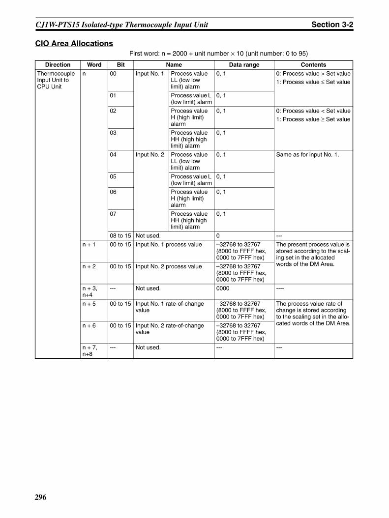
Section 3-2CJ1W-PTS15 Isolated-type Thermocouple Input Unit
CIO Area AllocationsFirst word: n = 2000 + unit number × 10 (unit number: 0 to 95)
Direction Word Bit Name Data range Contents
Thermocouple Input Unit to CPU Unit
n 00 Input No. 1 Process value LL (low low limit) alarm
0, 1 0: Process value > Set value1: Process value ≤ Set value
01 Process value L (low limit) alarm
0, 1
02 Process value H (high limit) alarm
0, 1 0: Process value < Set value1: Process value ≥ Set value
03 Process value HH (high high limit) alarm
0, 1
04 Input No. 2 Process value LL (low low limit) alarm
0, 1 Same as for input No. 1.
05 Process value L (low limit) alarm
0, 1
06 Process value H (high limit) alarm
0, 1
07 Process value HH (high high limit) alarm
0, 1
08 to 15 Not used. 0 ---
n + 1 00 to 15 Input No. 1 process value –32768 to 32767 (8000 to FFFF hex, 0000 to 7FFF hex)
The present process value is stored according to the scal-ing set in the allocated words of the DM Area.n + 2 00 to 15 Input No. 2 process value –32768 to 32767
(8000 to FFFF hex, 0000 to 7FFF hex)
n + 3, n+4
--- Not used. 0000 ----
n + 5 00 to 15 Input No. 1 rate-of-change value
–32768 to 32767 (8000 to FFFF hex, 0000 to 7FFF hex)
The process value rate of change is stored according to the scaling set in the allo-cated words of the DM Area.n + 6 00 to 15 Input No. 2 rate-of-change
value–32768 to 32767 (8000 to FFFF hex, 0000 to 7FFF hex)
n + 7, n+8
--- Not used. --- ---
296

Section 3-2CJ1W-PTS15 Isolated-type Thermocouple Input Unit
Note The External Power Supply Flag turns ON after external power is suppliedand the internal voltage stabilizes (which requires approximately 2 s). Theindicator on the front of the Unit will turn ON as soon as external power is sup-plied.
Thermocouple Input Unit to CPU Unit
n + 9 00 Input No. 1 Rate-of-change value L (low limit) alarm
0, 1 0: Rate-of-change value > Set value
1: Rate-of-change value ≤ Set value
01 Rate-of-change value H (high limit) alarm
0, 1 0: Rate-of-change value < Set value1: Rate-of-change value ≥ Set value
02 Input No. 2 Rate-of-change value L (low limit) alarm
0, 1 Same as for input No. 1.
03 Rate-of-change value H (high limit) alarm
0, 1
04 to 07 Not used. 0 ---
08 Input No. 1 input disconnec-tion
0, 1 0: Normal1: Disconnection
09 Input No. 2 input disconnec-tion
0, 1
10, 11 Not used. 0 ---
12 Cold junction sensor error 0, 1 0: Normal1: Error
13 Zero/span adjustment period end
0, 1 0: Adjustment enabled1: Adjustment ended
14 Zero/span adjustment period notice
0, 1 0: Adjustment enabled1: Notice period
15 External power supply 0, 1 0: External power supply not used1: External power supply used
Direction Word Bit Name Data range Contents
297

Section 3-2CJ1W-PTS15 Isolated-type Thermocouple Input Unit
Expansion Control/Monitor Area AllocationsFirst word: word p. (p = address specified in word o+1 in the area specified inword o in the Expansion Setting Area)
Direction Word Bit Name Data range Contents
CPU Unit to Thermocou-ple Input Unit
p 00 to 15
Not used. Not used. Not used.
p+1 00 Input No. 1 hold function selection 0, 1 0: Peak and bottom
1: Top and valley01 Input No. 2 hold function selection
02 to 07
Not used. 0 Not used.
08 Input No. 1 hold start 0, 1 0: Do not hold.1: Hold09 Input No. 2 hold start
10, 11 Not used. 0 Not used.
12 Input No. 1 hold value reset 0, 1 0: Normal operation1: Reset hold value.13 Input No. 2 hold value reset
14, 15 Not used. 0 Not used.
p+2 00 Input No. 1 zero/span adjustment update bit 0, 1 0: Normal operation1: Update adjustment date(Remains ON while writing external FROM.)
01 Input No. 2 zero/span adjustment update bit
02 to 15
Not used. 0 Not used.
298
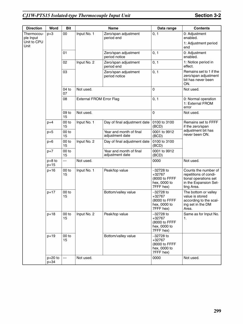
Section 3-2CJ1W-PTS15 Isolated-type Thermocouple Input Unit
Thermocou-ple Input Unit to CPU Unit
p+3 00 Input No. 1 Zero/span adjustment period end
0, 1 0: Adjustment enabled.
1: Adjustment period end
01 Zero/span adjustment period notice
0, 1 0: Adjustment enabled.1: Notice period in effect.Remains set to 1 if the zero/span adjustment bit has never been ON.
02 Input No. 2 Zero/span adjustment period end
0, 1
03 Zero/span adjustment period notice
0, 1
04 to 07
Not used. 0 Not used.
08 External FROM Error Flag 0, 1 0: Normal operation1: External FROM error
09 to 15
Not used. 0 Not used.
p+4 00 to 15
Input No. 1 Day of final adjustment date 0100 to 3100 (BCD)
Remains set to FFFF if the zero/span adjustment bit has never been ON.
p+5 00 to 15
Year and month of final adjustment date
0001 to 9912 (BCD)
p+6 00 to 15
Input No. 2 Day of final adjustment date 0100 to 3100 (BCD)
p+7 00 to 15
Year and month of final adjustment date
0001 to 9912 (BCD)
p+8 to p+15
--- Not used. 0000 Not used.
p+16 00 to 15
Input No. 1 Peak/top value −32728 to +32767 (8000 to FFFF hex, 0000 to 7FFF hex)
Counts the number of repetitions of condi-tional operations set in the Expansion Set-ting Area.
p+17 00 to 15
Bottom/valley value −32728 to +32767(8000 to FFFF hex, 0000 to 7FFF hex)
The bottom or valley value is stored according to the scal-ing set in the DM Area.
p+18 00 to 15
Input No. 2 Peak/top value −32728 to +32767(8000 to FFFF hex, 0000 to 7FFF hex)
Same as for Input No. 1.
p+19 00 to 15
Bottom/valley value −32728 to +32767(8000 to FFFF hex, 0000 to 7FFF hex)
p+20 to p+34
--- Not used. 0000 Not used.
Direction Word Bit Name Data range Contents
299

Section 3-2CJ1W-PTS15 Isolated-type Thermocouple Input Unit
Terminal Connection Diagram
Note Action for Unused Input Terminals
• Short-circuit the positive (+) and negative (−) sides of the thermocoupleinput section using a lead wire. For example, short terminals A4 and B5for No. 2 thermocouple input.
• Cold junction sensors are mounted between A1 and A2, and A6 and A7before shipment. If one of the cold junction sensors is disconnected, coldjunction compensation will stop and correct measurement of tempera-tures cannot be made. Always make sure the cold junction sensors areconnected when using the Units.
• Cold junction sensors are calibrated separately for each Unit and con-nected circuit, so correct temperatures will not be measured if a cold junc-tion sensor from another Unit is used or if the two cold junction sensors ina Unit are swapped. Use the cold junction sensors as they are provided,without making any changes.
• Always ground the GR terminal on the Power Supply Unit of the PLC.• If the input device uses a voltage generator, temperature compensator, or
similar device, then ground the input device if it has a ground terminal.
Terminal Block Diagram
NC
NC
NC
1+
2+
NC
NC
NC
0V
B1 (10)
B2 (11)
B3 (12)
B4 (13)
B5 (14)
B6 (15)
B7 (16)
B8 (17)
B9 (18)
CJ1+A1 (1)
CJ1−A2 (2)
1−A3 (3)
2−A4 (4)
NC A5 (5)
CJ2+A6 (6)
CJ2−A7 (7)
NC A8 (8)
24VA9 (9)
Thermocouple input 2
Cold junction sensor 2
Thermo-couple input 1
Cold junction sensor 1
24 VDC
5 VDC
B5
A4
A1A2
A6A7
Isolation circuitB4
A3
Isolation circuit
A9B9
No. 1 input
Thermocouples
No. 2 input
Upper
Lower
Cold junction sensors
Amplifier circuit
Amplifier circuit
Amplifier circuit
Amplifier circuit
A/D converter
A/D converter
A/D
con
vert
er
Mul
tiple
xer
Pho
toco
uple
r
Photocoupler
Photocoupler
Digital circuits
Con
nect
or
24-V power supply
Power sup-ply circuit
300
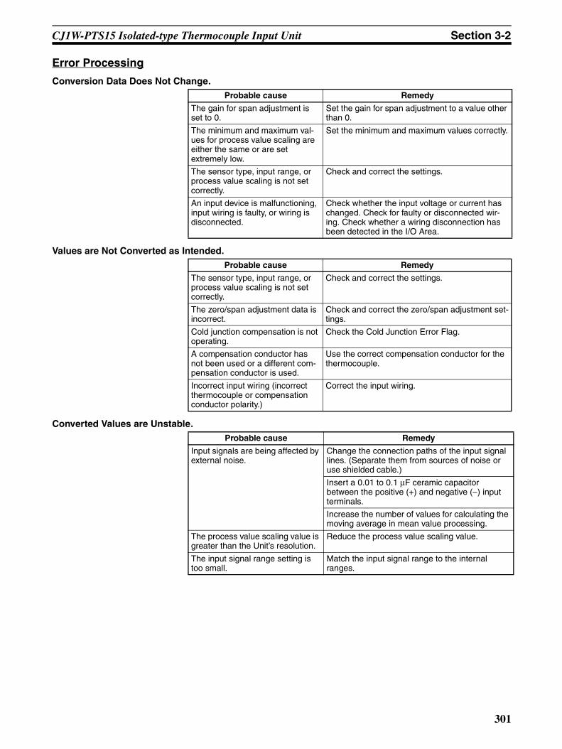
Section 3-2CJ1W-PTS15 Isolated-type Thermocouple Input Unit
Error Processing
Conversion Data Does Not Change.
Values are Not Converted as Intended.
Converted Values are Unstable.
Probable cause Remedy
The gain for span adjustment is set to 0.
Set the gain for span adjustment to a value other than 0.
The minimum and maximum val-ues for process value scaling are either the same or are set extremely low.
Set the minimum and maximum values correctly.
The sensor type, input range, or process value scaling is not set correctly.
Check and correct the settings.
An input device is malfunctioning, input wiring is faulty, or wiring is disconnected.
Check whether the input voltage or current has changed. Check for faulty or disconnected wir-ing. Check whether a wiring disconnection has been detected in the I/O Area.
Probable cause Remedy
The sensor type, input range, or process value scaling is not set correctly.
Check and correct the settings.
The zero/span adjustment data is incorrect.
Check and correct the zero/span adjustment set-tings.
Cold junction compensation is not operating.
Check the Cold Junction Error Flag.
A compensation conductor has not been used or a different com-pensation conductor is used.
Use the correct compensation conductor for the thermocouple.
Incorrect input wiring (incorrect thermocouple or compensation conductor polarity.)
Correct the input wiring.
Probable cause Remedy
Input signals are being affected by external noise.
Change the connection paths of the input signal lines. (Separate them from sources of noise or use shielded cable.)
Insert a 0.01 to 0.1 µF ceramic capacitor between the positive (+) and negative (−) input terminals.
Increase the number of values for calculating the moving average in mean value processing.
The process value scaling value is greater than the Unit’s resolution.
Reduce the process value scaling value.
The input signal range setting is too small.
Match the input signal range to the internal ranges.
301

Section 3-3CJ1W-PTS52 Isolated-type Resistance Thermometer Input Unit (Pt100, JPt100)
3-3 CJ1W-PTS52 Isolated-type Resistance Thermometer Input Unit (Pt100, JPt100)
OverviewThe CJ1W-PTS52 Isolated-type Resistance Thermometer Input Unit providesfour direct platinum resistance thermometer inputs, and sends the data to theCPU Unit each cycle. All inputs are isolated.
CJ1W-PTS52
System Configuration
Features• Up to four platinum resistance thermometers can be connected for each
Unit. (The temperature sensor and input range settings are the same forall four inputs.)
• Pt100 (JIS, IEC), JPt100 can be selected.• Temperature sensor values are transmitted to the CPU Unit in four digits
hexadecimal. (Either binary or BCD data output can be selected.)• Process value alarm (two alarms in internal memory and one external
alarm output for each input).• Alarm ON-delay timer and hysteresis for process value.• Zero/span adjustment capability during operation.• Sensor error detection.• Maximum or minimum process value can be specified for when a sensor
error is detected.
PTS52
MACH
No.
X101
X100
RUNERCERH
ALM
12
34
--
-
CJ1W-PTS52
Four platinum resistance thermometer inputs (Pt100 (JIS, IEC), JPt100)
302
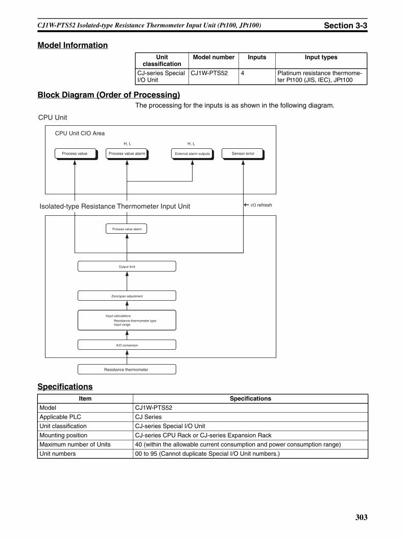
Section 3-3CJ1W-PTS52 Isolated-type Resistance Thermometer Input Unit (Pt100, JPt100)
Model Information
Block Diagram (Order of Processing)The processing for the inputs is as shown in the following diagram.
Specifications
Unit classification
Model number Inputs Input types
CJ-series Special I/O Unit
CJ1W-PTS52 4 Platinum resistance thermome-ter Pt100 (JIS, IEC), JPt100
Item Specifications
Model CJ1W-PTS52
Applicable PLC CJ Series
Unit classification CJ-series Special I/O Unit
Mounting position CJ-series CPU Rack or CJ-series Expansion Rack
Maximum number of Units 40 (within the allowable current consumption and power consumption range)
Unit numbers 00 to 95 (Cannot duplicate Special I/O Unit numbers.)
Process value alarm
Output limit
Zero/span adjustment
Input calculations
Resistance thermometer typeInput range
A/D conversion
Resistance thermometer
H, L H, L
CPU Unit
Process value Process value alarm Sensor errorExternal alarm outputs
CPU Unit CIO Area
Isolated-type Resistance Thermometer Input Unit I/O refresh
303
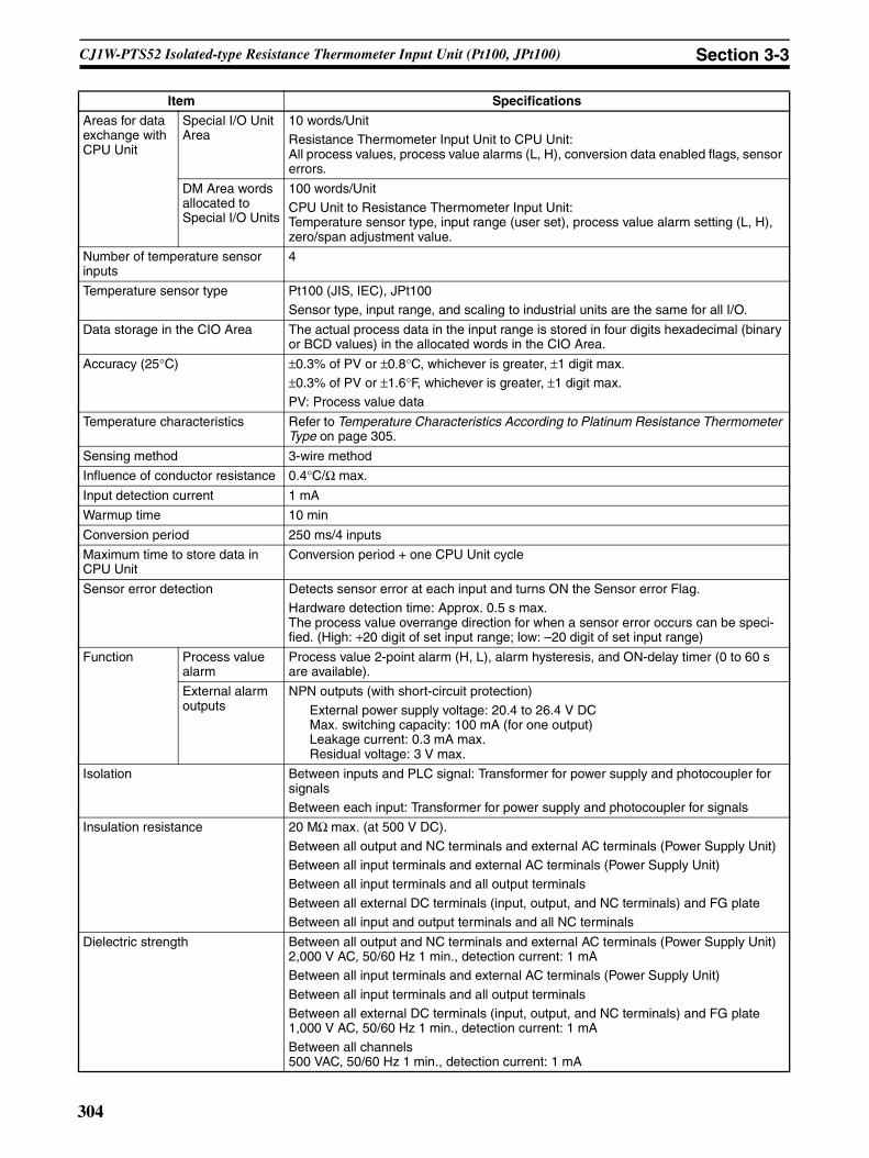
Section 3-3CJ1W-PTS52 Isolated-type Resistance Thermometer Input Unit (Pt100, JPt100)
Areas for data exchange with CPU Unit
Special I/O Unit Area
10 words/UnitResistance Thermometer Input Unit to CPU Unit:All process values, process value alarms (L, H), conversion data enabled flags, sensor errors.
DM Area words allocated to Special I/O Units
100 words/UnitCPU Unit to Resistance Thermometer Input Unit:Temperature sensor type, input range (user set), process value alarm setting (L, H), zero/span adjustment value.
Number of temperature sensor inputs
4
Temperature sensor type Pt100 (JIS, IEC), JPt100Sensor type, input range, and scaling to industrial units are the same for all I/O.
Data storage in the CIO Area The actual process data in the input range is stored in four digits hexadecimal (binary or BCD values) in the allocated words in the CIO Area.
Accuracy (25°C) ±0.3% of PV or ±0.8°C, whichever is greater, ±1 digit max. ±0.3% of PV or ±1.6°F, whichever is greater, ±1 digit max.PV: Process value data
Temperature characteristics Refer to Temperature Characteristics According to Platinum Resistance Thermometer Type on page 305.
Sensing method 3-wire method
Influence of conductor resistance 0.4°C/Ω max.
Input detection current 1 mA
Warmup time 10 min
Conversion period 250 ms/4 inputs
Maximum time to store data in CPU Unit
Conversion period + one CPU Unit cycle
Sensor error detection Detects sensor error at each input and turns ON the Sensor error Flag.Hardware detection time: Approx. 0.5 s max.The process value overrange direction for when a sensor error occurs can be speci-fied. (High: +20 digit of set input range; low: –20 digit of set input range)
Function Process value alarm
Process value 2-point alarm (H, L), alarm hysteresis, and ON-delay timer (0 to 60 s are available).
External alarm outputs
NPN outputs (with short-circuit protection)
External power supply voltage: 20.4 to 26.4 V DCMax. switching capacity: 100 mA (for one output) Leakage current: 0.3 mA max.Residual voltage: 3 V max.
Isolation Between inputs and PLC signal: Transformer for power supply and photocoupler for signalsBetween each input: Transformer for power supply and photocoupler for signals
Insulation resistance 20 MΩ max. (at 500 V DC).
Between all output and NC terminals and external AC terminals (Power Supply Unit)Between all input terminals and external AC terminals (Power Supply Unit)Between all input terminals and all output terminals
Between all external DC terminals (input, output, and NC terminals) and FG plateBetween all input and output terminals and all NC terminals
Dielectric strength Between all output and NC terminals and external AC terminals (Power Supply Unit)2,000 V AC, 50/60 Hz 1 min., detection current: 1 mABetween all input terminals and external AC terminals (Power Supply Unit)
Between all input terminals and all output terminalsBetween all external DC terminals (input, output, and NC terminals) and FG plate1,000 V AC, 50/60 Hz 1 min., detection current: 1 mA
Between all channels500 VAC, 50/60 Hz 1 min., detection current: 1 mA
Item Specifications
304

Section 3-3CJ1W-PTS52 Isolated-type Resistance Thermometer Input Unit (Pt100, JPt100)
Sensor Type and Input RangeThe Platinum Resistance Thermometer type and input range are set in theallocated words in the DM Area for every four inputs.
The measurable data range is ±20 digits wider than the sensor input range.
Note 1. If the indication range is exceeded, a sensor error will occur and the sensorerror bit will turn ON. The process value will be clamped at the lower or up-per limit of the indication range, depending on the setting for data directionat sensor error.
2. The indicator range for BCD display will be clamped at the lower (or upper)limit in the region between the lower (or upper) limit of the setting rangeand the point where a sensor error occurs.For 0.1°C/0.1°F indication with minus sign indicated by leftmost 4 bits (bits12 to 15): Lower limit = −99.9, Upper limit = 999.9.For 0.1°C/0.1°F indication with minus sign indicated by leftmost bit (bit 15):Lower limit = −799.9, Upper limit = 799.9.
Temperature Characteristics According to Platinum Resistance Thermometer Type
External connections Terminal block (detachable)
Unit number settings Set by rotary switches on front panel, from 0 to 95.
Indicators Seven LED indicators on front panel (for normal operation, errors detected at the Resistance Thermometer Input Unit, errors detected at the CPU Unit, and four indica-tors for external alarm outputs.)
Effect on CPU Unit cycle time 0.4 ms
Current consumption 5 V DC at 250 mA max
Dimensions 31 × 90 × 65 mm (W × H × D)
Note The height including the Backplane is 145 mm.
Weight 150 g max.
Item Specifications
Set-ting
Input °C °F16-bit binary BCD 16-bit binary BCD
F@@@ indicates
minus sign.
Leftmost bit indicates
minus sign.
Leftmost 4 bits (bits 15
to 12) indicate
minus sign.
Leftmost bit (bit 15)
indicates minus sign.
0 Pt100: −200.0 to 650.0°C(−300.0 to 1200.0°F)
F830 to FFFF to 1964(−200.0 to −0.1 to 650.0)
F999 to 6500 (See note 2.)(−99.9 to 650.0)
A000 to 6500(−200.0 to 650.0)
F448 to FFFF to 2EE0(−300.0 to −0.1 to 1200.0)
F999 to 9999 (See note 2.)(−99.9 to 999.9)
B000 to 7999 (See note 2.)(−300.0 to 799.9)
1 JPt100: −200.0 to 650.0°C(−300.0 to 1200.0°F)
F830 to FFFF to 1964(−200.0 to −0.1 to 650.0)
F999 to 6500 (See note 2.)(−99.9 to 650.0)
A000 to 6500(−200.0 to 650.0)
F448 to FFFF to 2EE0(−300.0 to −0.1 to 1200.0)
F999 to 9999 (See note 2.)(−99.9 to 999.9)
B000 to 7999 (See note 2.)(−300.0 to 799.9)
2 to 9 Do not set. Do not set.
Platinum Resistance Thermometer
Temperature range Set value error when ambient temperature
changes by 1°CPt100 −200 to 200°C ±0.06°C
200 to 650°C 285 ppm of PV
JPt100 −200 to 200°C ±0.06°C200 to 650°C 285 ppm of PV
305

Section 3-3CJ1W-PTS52 Isolated-type Resistance Thermometer Input Unit (Pt100, JPt100)
The measured temperature error is calculated as shown in the followingexample.
Overall accuracy = Reference accuracy + Temperature characteristic × Change in ambienttemperature = ±1.5°C + ±0.143°C × 5 = Approx. ±2.2°C ±1 digit.
Item Details
Ambient temperature 30°CPlatinum Resistance Thermometer
Pt100
Measured temperature (PV)
500°C
Reference accuracy (25°C)
±0.3°C of PV or ±0.8°C, whichever is greater, ±1 digit.
In this example, ±1.5°C.
Temperature characteris-tics
200 to 650°C: 285 ppm of PV.In this example, 285 ppm × 500°C = 0.143°C.
Change in ambient tem-perature
5°C (25 to 30°C)
306
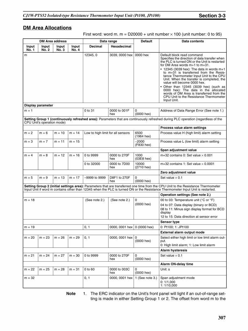
Section 3-3CJ1W-PTS52 Isolated-type Resistance Thermometer Input Unit (Pt100, JPt100)
DM Area AllocationsFirst word: word m. m = D20000 + unit number × 100 (unit number: 0 to 95)
Note 1. The ERC indicator on the Unit’s front panel will light if an out-of-range set-ting is made in either Setting Group 1 or 2. The offset from word m to the
DM Area address Data range Default Data contents
Input No. 1
Input No. 2
Input No. 3
Input No. 4
Decimal Hexadecimal
m 12345, 0 3039, 0000 hex 0000 hex Default block read commandSpecifies the direction of data transfer when the PLC is turned ON or the Unit is restarted for DM Area words m+1 to m+31.• 12345 (3039 hex): The data in words m+1
to m+31 is transferred from the Resis-tance Thermometer Input Unit to the CPUUnit. When the transfer is completed, thevalue will become 0000 hex.
• Other than 12345 (3039 hex) (such as0000 hex): The data in the allocatedwords of DM Area is transferred from theCPU Unit to the Resistance ThermometerInput Unit.
Display parameter
m + 1 0 to 31 0000 to 001F hex
0 (0000 hex)
Address of Data Range Error (See note 1.)
Setting Group 1 (continuously refreshed area): Parameters that are continuously refreshed during PLC operation (regardless of the CPU Unit’s operation mode)
Process value alarm settings
m + 2 m + 6 m + 10 m + 14 Low to high limit for all sensors 6500 (1964 hex)
Process value H (high limit) alarm setting
m + 3 m + 7 m + 11 m + 15 −2000 (F830 hex)
Process value L (low limit) alarm setting
Span adjustment value
m + 4 m + 8 m + 12 m + 16 0 to 9999 0000 to 270F hex
1000 (03E8 hex)
m+32 contains 0: Set value × 0.001
0 to 32000 0000 to 7D00 hex
10000 (2710 hex)
m+32 contains 1: Set value × 0.0001
Zero adjustment value
m + 5 m + 9 m + 13 m + 17 –9999 to 9999 D8F1 to 270F hex
0 (0000 hex)
Set value × 0.1
Setting Group 2 (initial settings area): Parameters that are transferred one time from the CPU Unit to the Resistance Thermometer Input Unit if word m contains other than 12345 when the PLC is turned ON or the Resistance Thermometer Input Unit is restarted.
Operation settings (See note 2.)
m + 18 (See note 2.) (See note 2.) 0(0000 hex)
00 to 03: Temperature unit (°C or °F)
04 to 07: Data display (binary or BCD)08 to 11: Minus sign display format for BCD display12 to 15: Data direction at sensor error
Sensor type
m + 19 0, 1 0000, 0001 hex 0 (0000 hex) 0: Pt100; 1: JPt100
External alarm output mode
m + 20 m + 23 m + 26 m + 29 0, 1 0000, 0001 hex 0 (0000 hex)
Select either high limit or low limit alarm out-put.0: High limit alarm; 1: Low limit alarm
Alarm hysteresis
m + 21 m + 24 m + 27 m + 30 0 to 9999 0000 to 270F hex
0 (0000 hex)
Set value × 0.1
Alarm ON-delay time
m + 22 m + 25 m + 28 m + 31 0 to 60 0000 to 003C hex
0 (0000 hex)
Unit: s
m + 32 0, 1 0000, 0001 hex 1 (See note 3.) Span adjustment mode0: 1/1,0001: 1/10,000
307

Section 3-3CJ1W-PTS52 Isolated-type Resistance Thermometer Input Unit (Pt100, JPt100)
first word containing the out-of-range error will be stored as the Address ofData Range Error in the DM Area in four digits hexadecimal.
2. The operation settings are shown in the following table.
Example: For a temperature in degrees Celsius (°C), a binary data format,and a data direction at sensor error of “lower limit,” word m+18 contains 1000.3. Indicates the value after transferring the default value (set when 12345 is
written to word m).
CIO Area AllocationsFirst word: word n. n = 2000 + unit number × 10 (unit number: 0 to 95)
Word Bits Description Settings
m+18 00 Temperature unit setting 0: °C1: °F
04 Data format 0: Binary (Negative values are given as 2’s comple-ments).
1: BCD
08 Minus sign display format for BCD display 0: “F” used to indicate the minus sign.1: Leftmost bit used to indicate the minus sign.
The setting is disabled if bits 04 to 07 are set to 0.
12 Data direction at sensor error 0: Goes to upper limit at sensor error
1: Goes to lower limit at sensor error
Direction Word Bit Name Data range Contents
Resistance Ther-mometer Input Unit to CPU Unit
n 00 Input No. 1 Process value L (low limit) alarm
0, 1 0: Process value > Set value1: Process value ≤ Set value
01 Process value H (high limit) alarm
0, 1 0: Process value < Set value1: Process value ≥ Set value
02 Input No. 2 Process value L (low limit) alarm
0, 1 Same as for input No. 1.
03 Process value H (high limit) alarm
0, 1
04 Input No. 3 Process value L (low limit) alarm
0, 1
05 Process value H (high limit) alarm
0, 1
06 Input No. 4 Process value L (low limit) alarm
0, 1
07 Process value H (high limit) alarm
0, 1
08 to 15 Not used.
n + 1 00 to 15 Input No. 1 Process value Depends on type of input. Stores data in the data range specified for each input type ±20 digits.
n + 2 00 to 15 Input No. 2
n + 3 00 to 15 Input No. 3
n + 4 00 to 15 Input No. 4
n + 5 Not used.
n + 6
n + 7
n + 8
308

Section 3-3CJ1W-PTS52 Isolated-type Resistance Thermometer Input Unit (Pt100, JPt100)
Note The Conversion Data Enabled Flag remains OFF after the PLC is turned ONor the Unit is restarted until the AD conversion data becomes stable (approxi-mately 2 to 4 s), then is ON during operation.
Terminal Connection Diagram
Note • Wire the same length to A, B, and b, so that the impedance will be thesame. In particular, do not short circuit between B and b at the terminalblock.
• For unused input terminals, connect approximately 100 Ω between theplatinum-resistance thermometer input terminals A and B and short termi-nals B and b with a lead wire. If resistance is not connected between ter-minals A and B and terminals B and b are shorted or if terminals A and Band terminals B and b are left open, the alarm output will turn ON and theALM indicator will light.
• Always ground the GR terminal on the Power Supply Unit of the PLC.• If the input device uses a voltage generator, temperature compensator, or
similar device, then ground the input device if it has a ground terminal.
Resistance Ther-mometer Input Unit to CPU Unit
n + 9 00 Input No. 1 Sensor error 0, 1 0: Normal1: Error01 Input No. 2 0, 1
02 Input No. 3 0, 1
03 Input No. 4 0, 1
04 to 14 Not used.
15 15 Conversion data enabled flag. (See note.)
0, 1 0: Data disabled1: Data enabled
Direction Word Bit Name Data range Contents
External alarm outputs
2b
2B
2A
4b
4B
4A
ALM2
ALM4
0V 0V
B1
B2
B3
B4
B5
B6
B7
B8
B9
A1
A2
A3
A4
A5
A6
A7
A8
A9
1b
1B
1A
3b
3B
3A
ALM1
ALM3
24V
External alarm outputsL
L
L
L
No. 2 Platinum-resistance Thermometer input
No. 4 Platinum-resistance Thermometer input
No. 1 Platinum-resistance Thermometer input
No. 3 Platinum-resistance Thermometer input
309

Section 3-3CJ1W-PTS52 Isolated-type Resistance Thermometer Input Unit (Pt100, JPt100)
Terminal Block Diagram
Input Circuit
Output Circuit
5 V DC
Con
nect
or
Amplifier circuit
PhotocouplerA1
Amplifier circuit
Photocoupler
Amplifier circuit
Photocoupler
Amplifier circuit
Photocoupler
Isol
atio
n ci
rcui
t
Digital circuits
1A
1B1b
A
BResistance thermometer
B3
B1B2
2A
2B2b
A
BResistance thermometer
A6
A3
A2
3A
3B3b
A
BResistance thermometer
B6
B4B5
4A
4B4b
A
BResistance thermometer
Double integral A/D
Reference power supply
Double integral A/D
Double integral A/D
Double integral A/D
Reference power supply
Reference power supply
Reference power supply
A4
A5
Inte
rnal
Circ
uit
L
L
L
L
Output DisplayLED
B7ALM2
A8ALM3
B8ALM4
B90V
A9 24V
A7ALM1
310

Section 3-3CJ1W-PTS52 Isolated-type Resistance Thermometer Input Unit (Pt100, JPt100)
Error Processing
Conversion Data Does Not Change.
Values are Not Converted as Intended.
Converted Values are Unstable.
Probable cause Remedy
The gain for span adjustment is set to 0.
Set the gain for span adjustment to a value other than 0.
The sensor type is not set cor-rectly.
Check and reset the sensor type.
An input device is malfunctioning, input wiring is faulty, or wiring is disconnected.
Check whether the resistance has changed. Check for faulty or disconnected wiring. Check whether a sensor error has been detected in the I/O Area.
Probable cause Remedy
The sensor type is set incorrectly. Check and reset the sensor type settings.
The zero/span adjustment data is incorrect.
Check and correct the zero/span adjustment set-tings.
The platinum-resistance thermom-eter input wiring is faulty.
Check and correct the input wiring.
The compensating conductor is too long and measurements are being affected by conductor resis-tance.
Use a thicker compensating conductor.
Probable cause Remedy
Input signals are being affected by external noise.
Change the connection paths of the input signal lines. (Separate them from sources of noise or use shielded cable.)
311

CJ1W-PTS16 Isolated-type Resistance Thermometer Input Unit (Pt100, JPt100, Pt50, Ni508.4) Section 3-4
3-4 CJ1W-PTS16 Isolated-type Resistance Thermometer Input Unit (Pt100, JPt100, Pt50, Ni508.4)
OverviewThe CS1W-PTS16 Isolated-type Resistance Thermometer Input Unit providestwo direct resistance thermometer inputs, and sends the data to the CPU Uniteach cycle. All inputs are isolated.
CS1W-PTS16
System Configuration
Features• Up to two resistance thermometers can be connected for each Unit (with
two separate settings for temperature sensors and input ranges).• Pt100 (JIS, IEC), JPt100, Pt50, or Ni508.4 can be selected.• 1/64,000 resolution for all temperature specifications.• High-speed conversion of 10 ms/2 inputs.• Temperature sensor values are transmitted to the CPU Unit in four digits
hexadecimal.• Variable input range setting.• Four values for each process value alarm input.• ON-delay timer for process value alarm.• Mean value processing.• Rate-of-change calculation.• Two values for each rate-of-change alarm input.• Zero/span adjustment capability during operation.• Disconnection detection.• Maximum or minimum process value can be specified for when a discon-
nection is detected.• Adjustment period control.
PTS16
MACH
No. 1
0
RUNERCERHEXT PS
CS1W-PTS16
Two resistance thermometer inputs (Pt100 (JIS, IEC), JPt100, Pt50, or Ni508.4)
312

CJ1W-PTS16 Isolated-type Resistance Thermometer Input Unit (Pt100, JPt100, Pt50, Ni508.4) Section 3-4
• Peak and bottom detection.• Top and valley detection.
Model Information
Block Diagram (Order of Processing)The processing for the inputs is as shown in the following diagram.
Unit classification
Model number Inputs Input types
CJ-series Special I/O Unit
CJ1W-PTS16 2 Resistance thermometer Pt100 (JIS, IEC), JPt100, Pt50, or Ni508.4
Process value alarm Rate-of-change alarm
Output limit: −15% to +115%
Rate-of-change calculation and scaling
+115% or −15% when input disconnection is detected
Output limit: −15% to +115%
Zero/span adjustment
Process value scaling
Input calculationsResistance thermometer typeInput range
A/D conversion, moving average
Resistance thermometer
Input disconnection check
HH, H, L, LL H, L
Top/valley value
CPU Unit
CPU Unit Expansion Area Allocations
Peak/Bottom value
Process value Process value alarm Rate-of-change value Rate-of-change alarm Input disconnection alarm
CPU Unit CIO Area
Isolated-type Resistance Thermometer Input Unit
24-V external power supply
I/O refresh
External power supply used/not used
313

CJ1W-PTS16 Isolated-type Resistance Thermometer Input Unit (Pt100, JPt100, Pt50, Ni508.4) Section 3-4
SpecificationsItem Specifications
Model CJ1W-PTS16
Applicable PLC CJ Series
Unit classification CJ-series Special I/O Unit
Mounting position CJ-series CPU Rack or CJ-series Expansion Rack
Maximum number of Units 40 (within the allowable current consumption and power consumption range)
Unit numbers 00 to 95 (Cannot duplicate Special I/O Unit numbers.)
Areas for data exchange with CPU Unit
Special I/O Unit Area
10 words/UnitResistance Thermometer Input Unit to CPU Unit:All process values, process value alarms (LL, L, H, HH), rate-of-change values, rate-of-change alarms (L, H), disconnection alarms, adjustment period end/notices.
DM Area words allocated to Special I/O Units
100 words/UnitCPU Unit to Resistance Thermometer Input Unit:Temperature sensor type, input range (user set), scaling of process value data to be stored in allocated words in CIO area, rate-of-change input range, scaling of rate-of-change data, number of items for moving average, process value alarm setting (LL, L, H, HH), rate-of-change alarm setting (L, H), zero/span adjustment value.
Expansion Con-trol/Monitor Area words
35 words/UnitCPU Unit to Resistance Thermometer Input Unit:Hold function selection start/reset, adjustment period control, control bits
Resistance Thermometer Input Unit to CPU Unit:Adjustment period warnings/notices, peak and bottom values, top and valley values
Expansion Set-ting Area words
46 words/UnitCPU Unit to Resistance Thermometer Input Unit:Expansion Setting Area settings, adjustment period control, peak and bottom detec-tion, top and valley detection
Number of temperature sensor inputs
2
Temperature sensor type Pt100 (JIS, IEC), JPt100, Pt50, Ni508.4Sensor type, input range, and scaling to industrial units are separate for each of the 2 inputs.
Scaling Data to be stored in the allocated words in the CIO area must be scaled (with the min-imum and maximum values set by user) (2 inputs set separately.). Data can be stored at 0% to 100%.
Data storage in the CIO Area The value derived from carrying out the following processing in order of the actual pro-cess data in the input range is stored in four digits hexadecimal (binary values) in the allocated words in the CIO Area.1) Mean value processing → 2) Scaling → 3) Zero/span adjustment → 4) Output limits
Accuracy (25°C) The greater of the following: ±0.05% or ±0.1°CTemperature coefficient Pt100: 0.009%/°C
JPt100: 0.01%/°CPt50: 0.02%/°CNi508.4: 0.012%/°C
Resolution 1/64,000
Sensing method 3-wire method
Allowable lead wire resistance 20 Ω max. per wire
Input detection current 0.5 mA
Warmup time 10 min
Response time 100 ms (travel time from input 0% to 90%, for step input and with moving average for 4 samples)
Conversion period 10 ms/2 inputs
Maximum time to store data in CPU Unit
Conversion period + one CPU Unit cycle
314
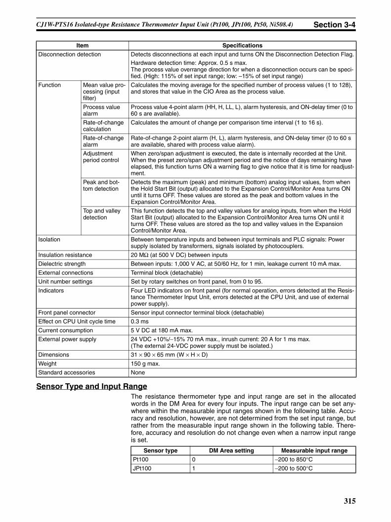
CJ1W-PTS16 Isolated-type Resistance Thermometer Input Unit (Pt100, JPt100, Pt50, Ni508.4) Section 3-4
Sensor Type and Input RangeThe resistance thermometer type and input range are set in the allocatedwords in the DM Area for every four inputs. The input range can be set any-where within the measurable input ranges shown in the following table. Accu-racy and resolution, however, are not determined from the set input range, butrather from the measurable input range shown in the following table. There-fore, accuracy and resolution do not change even when a narrow input rangeis set.
Disconnection detection Detects disconnections at each input and turns ON the Disconnection Detection Flag.Hardware detection time: Approx. 0.5 s max.The process value overrange direction for when a disconnection occurs can be speci-fied. (High: 115% of set input range; low: –15% of set input range)
Function Mean value pro-cessing (input filter)
Calculates the moving average for the specified number of process values (1 to 128), and stores that value in the CIO Area as the process value.
Process value alarm
Process value 4-point alarm (HH, H, LL, L), alarm hysteresis, and ON-delay timer (0 to 60 s are available).
Rate-of-change calculation
Calculates the amount of change per comparison time interval (1 to 16 s).
Rate-of-change alarm
Rate-of-change 2-point alarm (H, L), alarm hysteresis, and ON-delay timer (0 to 60 s are available, shared with process value alarm).
Adjustment period control
When zero/span adjustment is executed, the date is internally recorded at the Unit. When the preset zero/span adjustment period and the notice of days remaining have elapsed, this function turns ON a warning flag to give notice that it is time for readjust-ment.
Peak and bot-tom detection
Detects the maximum (peak) and minimum (bottom) analog input values, from when the Hold Start Bit (output) allocated to the Expansion Control/Monitor Area turns ON until it turns OFF. These values are stored as the peak and bottom values in the Expansion Control/Monitor Area.
Top and valley detection
This function detects the top and valley values for analog inputs, from when the Hold Start Bit (output) allocated to the Expansion Control/Monitor Area turns ON until it turns OFF. These values are stored as the top and valley values in the Expansion Control/Monitor Area.
Isolation Between temperature inputs and between input terminals and PLC signals: Power supply isolated by transformers, signals isolated by photocouplers.
Insulation resistance 20 MΩ (at 500 V DC) between inputs
Dielectric strength Between inputs: 1,000 V AC, at 50/60 Hz, for 1 min, leakage current 10 mA max.
External connections Terminal block (detachable)
Unit number settings Set by rotary switches on front panel, from 0 to 95.
Indicators Four LED indicators on front panel (for normal operation, errors detected at the Resis-tance Thermometer Input Unit, errors detected at the CPU Unit, and use of external power supply).
Front panel connector Sensor input connector terminal block (detachable)
Effect on CPU Unit cycle time 0.3 ms
Current consumption 5 V DC at 180 mA max.
External power supply 24 VDC +10%/−15% 70 mA max., inrush current: 20 A for 1 ms max.(The external 24-VDC power supply must be isolated.)
Dimensions 31 × 90 × 65 mm (W × H × D)
Weight 150 g max.
Standard accessories None
Item Specifications
Sensor type DM Area setting Measurable input range
Pt100 0 −200 to 850°CJPt100 1 −200 to 500°C
315
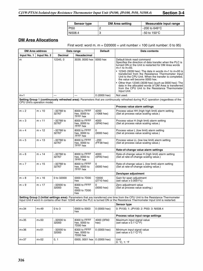
CJ1W-PTS16 Isolated-type Resistance Thermometer Input Unit (Pt100, JPt100, Pt50, Ni508.4) Section 3-4
DM Area AllocationsFirst word: word m. m = D20000 + unit number × 100 (unit number: 0 to 95)
Pt50 2 −200 to 649°CNi508.4 3 −50 to 150°C
Sensor type DM Area setting Measurable input range
DM Area address Data range Default Data contents
Input No. 1 Input No. 2 Decimal Hexadecimal
m 12345, 0 3039, 0000 hex 0000 hex Default block read commandSpecifies the direction of data transfer when the PLC is turned ON or the Unit is restarted for DM Area words m+1 to m+93.• 12345 (3039 hex): The data in words m+1 to m+93 is
transferred from the Resistance Thermometer InputUnit to the CPU Unit. When the transfer is completed,the value will become 0000 hex.
• Other than 12345 (3039 hex) (such as 0000 hex): Thedata in the allocated words of DM Area is transferredfrom the CPU Unit to the Resistance ThermometerInput Unit.
m+1 --- --- 0 (0000 hex) Not used.
Setting Group 1 (continuously refreshed area): Parameters that are continuously refreshed during PLC operation (regardless of the CPU Unit’s operation mode)
Process value alarm settings
m + 2 m + 10 –32768 to 32767
8000 to FFFF hex, 0000 to 7FFF hex
4200 (1068 hex)
Process value HH (high high limit) alarm setting(Set at process value scaling value.)
m + 3 m + 11 –32768 to 32767
8000 to FFFF hex, 0000 to 7FFF hex
4000 (0FA0 hex)
Process value H (high limit) alarm setting(Set at process value scaling value.)
m + 4 m + 12 –32768 to 32767
8000 to FFFF hex, 0000 to 7FFF hex
0 (0000 hex)
Process value L (low limit) alarm setting(Set at process value scaling value.)
m + 5 m + 13 –32768 to 32767
8000 to FFFF hex, 0000 to 7FFF hex
–200 (FF38 hex)
Process value LL (low low limit) alarm setting(Set at process value scaling value.)
Rate-of-change value alarm settings
m + 6 m + 14 –32768 to 32767
8000 to FFFF hex, 0000 to 7FFF hex
4000 (0FA0 hex)
Rate-of-change value H (high limit) alarm setting(Set at rate-of-change scaling value.)
m + 7 m + 15 –32768 to 32767
8000 to FFFF hex, 0000 to 7FFF hex
0 (0000 hex)
Rate-of-change value L (low limit) alarm setting(Set at rate-of-change scaling value.)
Zero/span adjustment
m + 8 m + 16 0 to 32000 0000 to 7D00 hex
10000 (2710 hex)
Gain for span adjustment(set value x 0.0001%)
m + 9 m + 17 –32000 to 32000
8300 to FFFF hex,0000 to 7D00 hex
0 (0000 hex)
Zero adjustment value(Set at process value scaling.)
Setting Group 2 (initial settings area): Parameters that are transferred one time from the CPU Unit to the Resistance Thermometer Input Unit if word m contains other than 12345 when the PLC is turned ON or the Resistance Thermometer Input Unit is restarted.
Sensor type
m+34 m+49 0 to 3 0000 to 0003 hex
0 (0000 hex) 0: Pt100; 1: JPt100: 2: Pt50: 3: Ni508.4
Process value input range settings
m+35 m+50 −32000 to 32000
8300 to FFFF hex, 0000 to 7D00 hex
4000 (0FA0 hex)
Maximum input signal value(set value x 0.1°C/°F)
m+36 m+51 −32000 to 32000
8300 to FFFF hex, 0000 to 7D00 hex
0 (0000 hex) Minimum input signal value(set value x 0.1°C/°F)
m+37 m+52 0, 1 0000, 0001 hex 0 (0000 hex) Unit0: °C, 1: °F
316
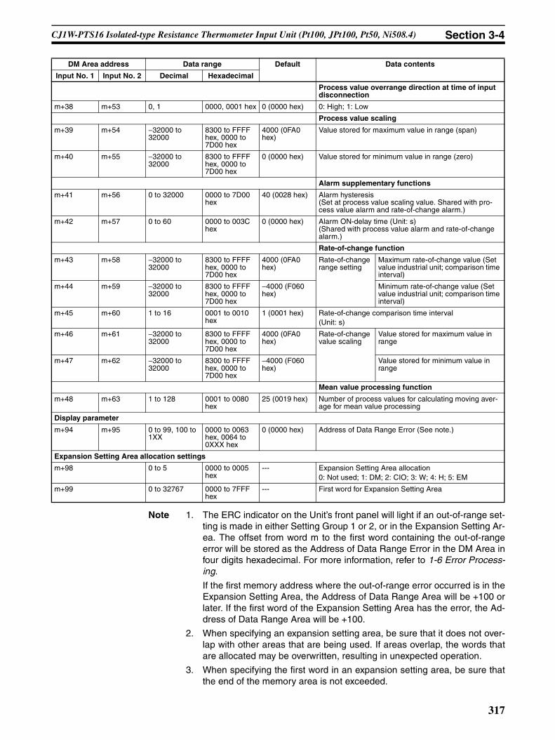
CJ1W-PTS16 Isolated-type Resistance Thermometer Input Unit (Pt100, JPt100, Pt50, Ni508.4) Section 3-4
Note 1. The ERC indicator on the Unit’s front panel will light if an out-of-range set-ting is made in either Setting Group 1 or 2, or in the Expansion Setting Ar-ea. The offset from word m to the first word containing the out-of-rangeerror will be stored as the Address of Data Range Error in the DM Area infour digits hexadecimal. For more information, refer to 1-6 Error Process-ing.
If the first memory address where the out-of-range error occurred is in theExpansion Setting Area, the Address of Data Range Area will be +100 orlater. If the first word of the Expansion Setting Area has the error, the Ad-dress of Data Range Area will be +100.
2. When specifying an expansion setting area, be sure that it does not over-lap with other areas that are being used. If areas overlap, the words thatare allocated may be overwritten, resulting in unexpected operation.
3. When specifying the first word in an expansion setting area, be sure thatthe end of the memory area is not exceeded.
Process value overrange direction at time of input disconnection
m+38 m+53 0, 1 0000, 0001 hex 0 (0000 hex) 0: High; 1: Low
Process value scaling
m+39 m+54 −32000 to 32000
8300 to FFFF hex, 0000 to 7D00 hex
4000 (0FA0 hex)
Value stored for maximum value in range (span)
m+40 m+55 −32000 to 32000
8300 to FFFF hex, 0000 to 7D00 hex
0 (0000 hex) Value stored for minimum value in range (zero)
Alarm supplementary functions
m+41 m+56 0 to 32000 0000 to 7D00 hex
40 (0028 hex) Alarm hysteresis(Set at process value scaling value. Shared with pro-cess value alarm and rate-of-change alarm.)
m+42 m+57 0 to 60 0000 to 003C hex
0 (0000 hex) Alarm ON-delay time (Unit: s)(Shared with process value alarm and rate-of-change alarm.)
Rate-of-change function
m+43 m+58 −32000 to 32000
8300 to FFFF hex, 0000 to 7D00 hex
4000 (0FA0 hex)
Rate-of-change range setting
Maximum rate-of-change value (Set value industrial unit; comparison time interval)
m+44 m+59 −32000 to 32000
8300 to FFFF hex, 0000 to 7D00 hex
−4000 (F060 hex)
Minimum rate-of-change value (Set value industrial unit; comparison time interval)
m+45 m+60 1 to 16 0001 to 0010 hex
1 (0001 hex) Rate-of-change comparison time interval(Unit: s)
m+46 m+61 −32000 to 32000
8300 to FFFF hex, 0000 to 7D00 hex
4000 (0FA0 hex)
Rate-of-change value scaling
Value stored for maximum value in range
m+47 m+62 −32000 to 32000
8300 to FFFF hex, 0000 to 7D00 hex
−4000 (F060 hex)
Value stored for minimum value in range
Mean value processing function
m+48 m+63 1 to 128 0001 to 0080 hex
25 (0019 hex) Number of process values for calculating moving aver-age for mean value processing
Display parameter
m+94 m+95 0 to 99, 100 to 1XX
0000 to 0063 hex, 0064 to 0XXX hex
0 (0000 hex) Address of Data Range Error (See note.)
Expansion Setting Area allocation settings
m+98 0 to 5 0000 to 0005 hex
--- Expansion Setting Area allocation0: Not used; 1: DM; 2: CIO; 3: W; 4: H; 5: EM
m+99 0 to 32767 0000 to 7FFF hex
--- First word for Expansion Setting Area
DM Area address Data range Default Data contents
Input No. 1 Input No. 2 Decimal Hexadecimal
317
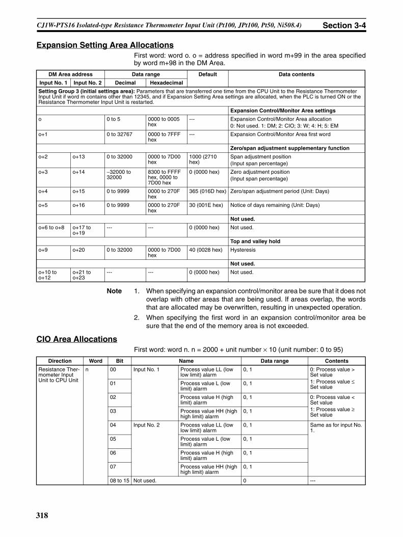
CJ1W-PTS16 Isolated-type Resistance Thermometer Input Unit (Pt100, JPt100, Pt50, Ni508.4) Section 3-4
Expansion Setting Area AllocationsFirst word: word o. o = address specified in word m+99 in the area specifiedby word m+98 in the DM Area.
Note 1. When specifying an expansion control/monitor area be sure that it does notoverlap with other areas that are being used. If areas overlap, the wordsthat are allocated may be overwritten, resulting in unexpected operation.
2. When specifying the first word in an expansion control/monitor area besure that the end of the memory area is not exceeded.
CIO Area AllocationsFirst word: word n. n = 2000 + unit number × 10 (unit number: 0 to 95)
DM Area address Data range Default Data contents
Input No. 1 Input No. 2 Decimal Hexadecimal
Setting Group 3 (initial settings area): Parameters that are transferred one time from the CPU Unit to the Resistance Thermometer Input Unit if word m contains other than 12345, and if Expansion Setting Area settings are allocated, when the PLC is turned ON or the Resistance Thermometer Input Unit is restarted.
Expansion Control/Monitor Area settings
o 0 to 5 0000 to 0005 hex
--- Expansion Control/Monitor Area allocation0: Not used. 1: DM; 2: CIO; 3: W; 4: H; 5: EM
o+1 0 to 32767 0000 to 7FFF hex
--- Expansion Control/Monitor Area first word
Zero/span adjustment supplementary function
o+2 o+13 0 to 32000 0000 to 7D00 hex
1000 (2710 hex)
Span adjustment position(Input span percentage)
o+3 o+14 −32000 to 32000
8300 to FFFF hex, 0000 to 7D00 hex
0 (0000 hex) Zero adjustment position(Input span percentage)
o+4 o+15 0 to 9999 0000 to 270F hex
365 (016D hex) Zero/span adjustment period (Unit: Days)
o+5 o+16 0 to 9999 0000 to 270F hex
30 (001E hex) Notice of days remaining (Unit: Days)
Not used.
o+6 to o+8 o+17 to o+19
--- --- 0 (0000 hex) Not used.
Top and valley hold
o+9 o+20 0 to 32000 0000 to 7D00 hex
40 (0028 hex) Hysteresis
Not used.
o+10 to o+12
o+21 to o+23
--- --- 0 (0000 hex) Not used.
Direction Word Bit Name Data range Contents
Resistance Ther-mometer Input Unit to CPU Unit
n 00 Input No. 1 Process value LL (low low limit) alarm
0, 1 0: Process value > Set value1: Process value ≤ Set value
01 Process value L (low limit) alarm
0, 1
02 Process value H (high limit) alarm
0, 1 0: Process value < Set value1: Process value ≥ Set value
03 Process value HH (high high limit) alarm
0, 1
04 Input No. 2 Process value LL (low low limit) alarm
0, 1 Same as for input No. 1.
05 Process value L (low limit) alarm
0, 1
06 Process value H (high limit) alarm
0, 1
07 Process value HH (high high limit) alarm
0, 1
08 to 15 Not used. 0 ---
318

CJ1W-PTS16 Isolated-type Resistance Thermometer Input Unit (Pt100, JPt100, Pt50, Ni508.4) Section 3-4
Note The External Power Supply Flag turns ON after external power is suppliedand the internal voltage stabilizes (which requires approximately 2 s). Theindicator on the front of the Unit will turn ON as soon as external power is sup-plied.
Resistance Ther-mometer Input Unit to CPU Unit
n + 1 00 to 15 Input No. 1 process value –32768 to 32767 (8000 to FFFF hex, 0000 to 7FFF hex)
The present process value is stored according to the scal-ing set in the allo-cated words of the DM Area.
n + 2 00 to 15 Input No. 2 process value –32768 to 32767 (8000 to FFFF hex, 0000 to 7FFF hex)
n + 3, n + 4
--- Not used. 0000 ---
n + 5 00 to 15 Input No. 1 rate-of-change value –32768 to 32767 (8000 to FFFF hex, 0000 to 7FFF hex)
The present rate of change is stored according to the scal-ing set in the allo-cated words of the DM Area.
n + 6 00 to 15 Input No. 2 rate-of-change value –32768 to 32767 (8000 to FFFF hex, 0000 to 7FFF hex)
n + 7, n + 8
--- Not used. 0000 ---
n + 9 00 Input No. 1 Rate-of-change value L (low limit) alarm
0, 1 0: Rate-of-change value > Set value1: Rate-of-change value ≤ Set value
01 Rate-of-change value H (high limit) alarm
0, 1 0: Rate-of-change value < Set value1: Rate-of-change value ≥ Set value
02 Input No. 2 Rate-of-change value L (low limit) alarm
0, 1 Same as for input No. 1.
03 Rate-of-change value H (high limit) alarm
0, 1
04 to 07 Not used. 0 ---08 Input No. 1 input error 0, 1 0: Normal
1: Disconnection 09 Input No. 2 input error 0, 1
10 to 12 Not used. 0 ---13 Zero/span adjustment period end 0, 1 0: Adjustment
enabled1: Adjustment ended
14 Zero/span adjustment period notice 0, 1 0: Adjustment enabled1: Notice period
15 External power supply 0, 1 0: External power supply not used1: External power supply used
Direction Word Bit Name Data range Contents
319

CJ1W-PTS16 Isolated-type Resistance Thermometer Input Unit (Pt100, JPt100, Pt50, Ni508.4) Section 3-4
Expansion Control/Monitor Area AllocationsFirst word: word p. p = address specified in word o+1 in the area specified byword o in the Expansion Setting Area.
Direction Word Bit Name Data range Contents
CPU Unit to Resistance Thermome-ter Input Unit
p 00 to 15
Not used. Not used. Not used.
p+1 00 Input No. 1 hold function selec-tion
0, 1 0: Peak and bottom
1: Top and valley01 Input No. 2 hold function selec-
tion0, 1
02 to 07
Not used. 0 Not used.
08 Input No. 1 hold start 0, 1 0: Do not hold.1: Hold09 Input No. 2 hold start 0, 1
10, 11 Not used. 0 Not used.
12 Input No. 1 hold value reset 0, 1 0: Normal opera-tion1: Reset hold value.
13 Input No. 2 hold value reset 0, 1
14, 15 Not used. 0 Not used.
p+2 00 Input No. 1 zero/span adjustment update bit
0, 1 0: Normal opera-tion1: Update adjust-ment date(Remains ON while writing external FROM.)
01 Input No. 2 zero/span adjustment update bit
0, 1
02 to 15
Not used. 0 Not used.
320

CJ1W-PTS16 Isolated-type Resistance Thermometer Input Unit (Pt100, JPt100, Pt50, Ni508.4) Section 3-4
Resistance Thermome-ter Input Unit to CPU Unit
p+3 00 Input No. 1
Zero/span adjustment period end
0, 1 0: Adjustment enabled.
1: Adjustment period end
01 Zero/span adjustment period notice
0, 1 0: Adjustment enabled.1: Notice period in effect.Remains set to 1 if the zero/span adjustment bit has never been ON.
02 Input No. 2
Zero/span adjustment period end
0, 1
03 Zero/span adjustment period notice
0, 1
04 to 07
Not used. 0 Not used.
08 External FROM Error Flag 0, 1 0: Normal opera-tion1: External FROM error
09 to 15
Not used. 0 Not used.
p+4 00 to 15
Input No. 1
Day of final adjustment date
0100 to 3100 (BCD) Remains set to FFFF if the zero/span adjustment bit has never been ON.
p+5 00 to 15
Year and month of final adjustment date
0001 to 9912 (BCD)
p+6 00 to 15
Input No. 2
Day of final adjustment date
0100 to 3100 (BCD)
p+7 00 to 15
Year and month of final adjustment date
0001 to 9912 (BCD)
p+8 to p+15
--- Not used. 0 Not used.
p+16 00 to 15
Input No. 1
Peak/top value −32728 to +32767(8000 to FFFF hex, 0000 to 7FFF hex)
Counts the num-ber of repetitions of conditional opera-tions set in the Expansion Setting Area.
p+17 00 to 15
Bottom/valley value −32728 to +32767(8000 to FFFF hex, 0000 to 7FFF hex)
The bottom or val-ley value is stored according to the scaling set in the DM Area.
p+18 00 to 15
Input No. 2
Peak/top value −32728 to +32767(8000 to FFFF hex, 0000 to 7FFF hex)
Same as for Input No. 1.
p+19 00 to 15
Bottom/valley value −32728 to +32767(8000 to FFFF hex, 0000 to 7FFF hex)
p+20 to p+34
--- Not used. 0 (0000 hex) Not used.
Direction Word Bit Name Data range Contents
321

CJ1W-PTS16 Isolated-type Resistance Thermometer Input Unit (Pt100, JPt100, Pt50, Ni508.4) Section 3-4
Terminal Connection Diagram
Note • Wire the same length to A, B, and b, so that the impedance will be thesame. In particular, do not short circuit between B and b at the terminalblock.
• For unused input terminals, short-circuit between A–B and B–b (e.g., B4–B5 and B5–B6 for input No. 2) of the resistance thermometer inputs withthe lead wire.
• Always ground the GR terminal on the Power Supply Unit of the PLC.• If the input device uses a voltage generator, temperature compensator, or
similar device, then ground the input device if it has a ground terminal.
Terminal Block Diagram
Error Processing
Conversion Data Does Not Change.
B1 (10)
B2 (11)
B3 (12)
B4 (13)
B5 (14)
B6 (15)
B7 (16)
B8 (17)
B9 (18)
NC A1 (1)
1AA2 (2)
1BA3 (3)
1bA4 (4)
NC A5 (5)
NC A6 (6)
NC A7 (7)
NC A8 (8)
24VA9 (9)
NC
NC
NC
2A
2B
2b
NC
NC
0V
Resistance thermometer input 2
Resistance thermometer input 1
24 VDC
Probable cause Remedy
The gain for span adjustment is set to 0.
Set the gain for span adjustment to a value other than 0.
The minimum and maximum val-ues for process value scaling are either the same or are set extremely low.
Set the minimum and maximum process value scaling correctly.
The sensor type, or process value scaling is not set correctly.
Check and reset the sensor type, and the pro-cess value scaling settings.
An input device is malfunctioning, input wiring is faulty, or wiring is disconnected.
Check whether the input voltage or current has changed. Check for faulty or disconnected wir-ing. Check whether a disconnection has been detected in the I/O Area.
5 VDC
A2
A3
A4
B4
B5
B6
1A
1B
1b
A
B
2A
2B
2b
A
B
510 Ω
510 Ω
A9
B9
Resistance thermometer
Resistance thermometer
24-VDC circuit
Reference resistance
Reference resistance
Constant current circuit
Constant current circuit
Am-plifier circuit
A/D con-verter
Am-plifier circuit
A/D con-verter
Constant current circuit
Constant current circuit
Power supply circuit
Isolation circuit
Photocoupler
Photocoupler
Isolation circuit
Inpu
t sel
ecto
r
Con
nect
or
Digital circuits
322

CJ1W-PTS16 Isolated-type Resistance Thermometer Input Unit (Pt100, JPt100, Pt50, Ni508.4) Section 3-4
Values are Not Converted as Intended.
Converted Values are Unstable.
Probable cause Remedy
The sensor type, or process value scaling is set incorrectly.
Check and reset the sensor type, and the pro-cess value scaling settings.
The zero/span adjustment data is incorrect.
Check and correct the zero/span adjustment set-tings.
The resistance thermometer input wiring is faulty.
Check and correct the input wiring.
Probable cause Remedy
Input signals are being affected by external noise.
Change the connection paths of the input signal lines. (Separate them from sources of noise or use shielded cable.)
Increase the number of values for calculating the moving average in mean value processing.
The scaling value is greater than the Unit’s resolution.
Reduce the process value scaling.
The input signal range is too small. Change to match the internal range.
323
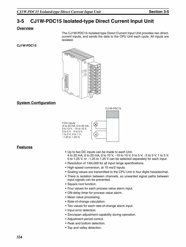
CJ1W-PDC15 Isolated-type Direct Current Input Unit Section 3-5
3-5 CJ1W-PDC15 Isolated-type Direct Current Input UnitOverview
The CJ1W-PDC15 Isolated-type Direct Current Input Unit provides two direct-current inputs, and sends the data to the CPU Unit each cycle. All inputs areisolated.
CJ1W-PDC15
System Configuration
Features• Up to two DC inputs can be made to each Unit.
4 to 20 mA, 0 to 20 mA, 0 to 10 V, −10 to 10 V, 0 to 5 V, −5 to 5 V, 1 to 5 V,0 to 1.25 V, or −1.25 to 1.25 V can be selected separately for each input.
• Resolution of 1/64,000 for all input range specifications.• High-speed conversion, at 10 ms/2 inputs.• Scaling values are transmitted to the CPU Unit in four digits hexadecimal.• There is isolation between channels, so unwanted signal paths between
input signals can be prevented.• Square root function.• Four values for each process value alarm input.• ON-delay timer for process value alarm.• Mean value processing.• Rate-of-change calculation.• Two values for each rate-of-change alarm input.• Input error detection.• Zero/span adjustment capability during operation.• Adjustment period control.• Peak and bottom detection.• Top and valley detection.
PDC15
MACH
No. 1
0
RUNERCERHEXT PS
CJ1W-PDC15
2 DC inputs(4 to 20 mA, 0 to 20 mA, 0 to 10 V, −10 to 10 V, 0 to 5 V, −5 to 5 V, 1 to 5 V, 0 to 1 V, −1.25 to 1.25 V)
324

CJ1W-PDC15 Isolated-type Direct Current Input Unit Section 3-5
• Integral value calculation.
Model Information
Block Diagram
Specifications
Unit classification Model number Inputs Input types
CJ-series Special I/O Unit
CJ1W-PDC15 2 4 to 20 mA, 0 to 20 mA, 0 to 10 V, −10 to 10 V, 0 to 5 V, −5 to 5 V, 1 to 5 V, 0 to 1.25 V, and −1.25 to 1.25 V (separate for each input)
Item Specifications
Model CJ1W-PDC15
Applicable PLC CJ Series
Unit classification CJ-series Special I/O Unit
Process value alarm Rate-of-change alarm
Output limit: −15% to +115%
Rate-of-change calculation and scaling
+115% or −15% when input disconnection is detected
Square root
Zero/span adjustment
Process value scaling
Input calculationsInput range
A/D conversion, moving average
DC signal sensor
Input error check
HH, H, L, LL H, L
Top/valley value
CPU Unit
CPU Unit Expansion Area Allocations
Peak/Bottom value
Process value Process value alarm Rate-of-change value Rate-of-change alarm Input error alarm
CPU Unit CIO Area
Isolated-type Direct Current Input Unit
External power supply used/not used
24-V external power supply
I/O refresh
There is no check for other inputs.
For 4 to 20 mA and 1 to 5 V inputs, less than −17% or more than 112% is an input error.
325

CJ1W-PDC15 Isolated-type Direct Current Input Unit Section 3-5
Mounting position CJ-series CPU Rack or CJ-series Expansion Rack
Maximum number of Units 40 (within the allowable current consumption and power consumption range)
Unit numbers 00 to 95 (Cannot duplicate Special I/O Unit numbers.)
Areas for data exchange with CPU Unit
Special I/O Unit Area
10 words/UnitDirect Current Input Unit to CPU Unit:All process values, process value alarms (LL, L, H, HH), rate-of-change values, rate-of-change alarms (L, H), disconnection alarms, cold junction sensor errors, adjust-ment period end/notice
DM Area words allocated to Special I/O Units
100 words/Unit
CPU Unit to Direct Current Input Unit:Input signal type, scaling of process value in industrial units, process value alarm set-ting (L, H), inrush input upper limit, inrush input upper limit time, zero/span adjustment value, Square root function.Temperature input signal type, input range (user set), scaling of process value data to be stored in allocated words in CIO area, rate-of-change input range, scaling of rate-of-change data, number of items for moving average, process value alarm setting (LL, L, H, HH), rate-of-change alarm setting (L, H), zero/span adjustment value
Expansion Con-trol/Monitor Area
35 words/Unit CPU Unit to Direct Current Input Unit:Bits for beginning or resetting the hold function selection, adjustment period control, control bitsDirect Current Input Unit to CPU Unit:Adjustment period notices, peak and bottom values, top and valley values, integral val-ues
Expansion Set-ting Area
46 words/UnitCPU Unit to Direct Current Input Unit:
Expansion Setting Area settings, adjustment period control, peak and bottom detec-tion, top and valley detection, integral value calculation
Number of inputs 2
Input signal type 4 to 20 mA, 0 to 20 mA, 0 to 10 V, −10 to 10 V, 0 to 5 V, −5 to 5 V, 1 to 5 V, 0 to 1.25 V, −1.25 to 1.25 V (separate for each input), and ±10-V user-set range (specified range within –10.000 V to 10.000 V)
Scaling Data to be stored in the allocated words in the CIO area must be scaled (Any mini-mum and maximum values can be set.) (2 inputs set separately.) Data can be con-verted at 0% to 100%.
Data storage in the CIO Area The value derived from carrying out the following processing in order of the actual pro-cess data in the input range is stored in four digits hexadecimal (binary values) in the allocated words in the CIO Area.1) Mean value processing → 2) Scaling → 3) Zero/span adjustment → 4) Square root calculation → 5) Output limits
Accuracy (25°C) ±0.05%
Temperature coefficient ±0.008%/°CResolution 1/64,000
Input signal range For 4 to 20 mA, 0 to 20 mA, 0 to 10 V, 0 to 5 V, 1 to 5 V, 0 to 1.25 V inputs:−15 to 115%
For −10 to 10 V, −5 to 5 V, −1.25 to 1.25 V inputs: −7.5 to 107.5%
Maximum input rating Voltage: ±15 VCurrent: ±30 mA
Input impedance For current inputs: 250 Ω (typical)For voltage inputs: 1 MΩ min.
Warmup time 10 min
Conversion period 10 ms/2 inputs
Maximum time to store data in CPU Unit
Conversion period + one CPU Unit cycle
Item Specifications
326
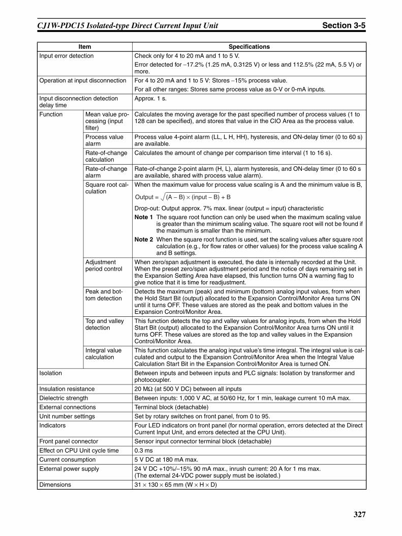
CJ1W-PDC15 Isolated-type Direct Current Input Unit Section 3-5
Input error detection Check only for 4 to 20 mA and 1 to 5 V.Error detected for −17.2% (1.25 mA, 0.3125 V) or less and 112.5% (22 mA, 5.5 V) or more.
Operation at input disconnection For 4 to 20 mA and 1 to 5 V: Stores −15% process value.
For all other ranges: Stores same process value as 0-V or 0-mA inputs.
Input disconnection detection delay time
Approx. 1 s.
Function Mean value pro-cessing (input filter)
Calculates the moving average for the past specified number of process values (1 to 128 can be specified), and stores that value in the CIO Area as the process value.
Process value alarm
Process value 4-point alarm (LL, L H, HH), hysteresis, and ON-delay timer (0 to 60 s) are available.
Rate-of-change calculation
Calculates the amount of change per comparison time interval (1 to 16 s).
Rate-of-change alarm
Rate-of-change 2-point alarm (H, L), alarm hysteresis, and ON-delay timer (0 to 60 s are available, shared with process value alarm).
Square root cal-culation
When the maximum value for process value scaling is A and the minimum value is B,
Drop-out: Output approx. 7% max. linear (output = input) characteristic
Note 1 The square root function can only be used when the maximum scaling value is greater than the minimum scaling value. The square root will not be found if the maximum is smaller than the minimum.
Note 2 When the square root function is used, set the scaling values after square root calculation (e.g., for flow rates or other values) for the process value scaling A and B settings.
Adjustment period control
When zero/span adjustment is executed, the date is internally recorded at the Unit. When the preset zero/span adjustment period and the notice of days remaining set in the Expansion Setting Area have elapsed, this function turns ON a warning flag to give notice that it is time for readjustment.
Peak and bot-tom detection
Detects the maximum (peak) and minimum (bottom) analog input values, from when the Hold Start Bit (output) allocated to the Expansion Control/Monitor Area turns ON until it turns OFF. These values are stored as the peak and bottom values in the Expansion Control/Monitor Area.
Top and valley detection
This function detects the top and valley values for analog inputs, from when the Hold Start Bit (output) allocated to the Expansion Control/Monitor Area turns ON until it turns OFF. These values are stored as the top and valley values in the Expansion Control/Monitor Area.
Integral value calculation
This function calculates the analog input value’s time integral. The integral value is cal-culated and output to the Expansion Control/Monitor Area when the Integral Value Calculation Start Bit in the Expansion Control/Monitor Area is turned ON.
Isolation Between inputs and between inputs and PLC signals: Isolation by transformer and photocoupler.
Insulation resistance 20 MΩ (at 500 V DC) between all inputs
Dielectric strength Between inputs: 1,000 V AC, at 50/60 Hz, for 1 min, leakage current 10 mA max.
External connections Terminal block (detachable)
Unit number settings Set by rotary switches on front panel, from 0 to 95.
Indicators Four LED indicators on front panel (for normal operation, errors detected at the Direct Current Input Unit, and errors detected at the CPU Unit).
Front panel connector Sensor input connector terminal block (detachable)
Effect on CPU Unit cycle time 0.3 ms
Current consumption 5 V DC at 180 mA max.
External power supply 24 V DC +10%/−15% 90 mA max., inrush current: 20 A for 1 ms max.(The external 24-VDC power supply must be isolated.)
Dimensions 31 × 130 × 65 mm (W × H × D)
Item Specifications
(A − B) × (input − B) + BOutput =
327

CJ1W-PDC15 Isolated-type Direct Current Input Unit Section 3-5
Accuracy and Resolution in ±10-V User-set RangeThe ±10-V user-set range allows the input signal’s input range to be set to anyrange within –10.000 V to 10.000 V. Accuracy and resolution, however, arenot determined by the input range, but rather by the measurable input range(–10.000 V to 10.000 V). Therefore, accuracy and resolution do not changeeven if a narrow input range is set.
DM Area AllocationsFirst word: word m. m = D20000 + unit number × 100 (unit number: 0 to 95)
Weight 150 g max.
Standard accessories Short bars (for current input)
Item Specifications
DM Area address Data range Default Data contents
Input No. 1 Input No. 2 Decimal Hexadecimal
m 12345, 0 3039, 0000 hex 0000 hex Default block read commandSpecifies the direction of data transfer when the PLC is turned ON or the Unit is restarted for DM Area words m+1 to m+93.• 12345 (3039 hex): The data in words m+1 to m+93 is
transferred from the Direct Current Input Unit to theCPU Unit. When the transfer is completed, the valuewill become 0000 hex.
• Other than 12345 (such as 0000 hex): The data in theallocated words of DM Area is transferred from theCPU Unit to the Direct Current Input Unit.
m+1 --- --- 0 (0000 hex) Not used.
Setting Group 1 (continuously refreshed area): Parameters that are continuously refreshed during PLC operation (regardless of the CPU Unit’s operation mode)
Process value alarm settings
m+2 m+10 –32768 to 32767
8000 to FFFF hex, 0000 to 7FFF hex
4200 (1068 hex)
Process value HH (high high limit) alarm setting(Set at process value scaling value.)
m+3 m+11 –32768 to 32767
8000 to FFFF hex, 0000 to 7FFF hex
4000 (0FA0 hex)
Process value H (high limit) alarm setting(Set at process value scaling value.)
m+4 m+12 –32768 to 32767
8000 to FFFF hex, 0000 to 7FFF hex
0 (0000 hex) Process value L (low limit) alarm setting(Set at process value scaling value.)
m+5 m+13 –32768 to 32767
8000 to FFFF hex, 0000 to 7FFF hex
–200 (FF38 hex)
Process value LL (low low limit) alarm setting(Set at process value scaling value.)
Rate-of-change value alarm settings
m+6 m+14 –32768 to 32767
8000 to FFFF hex, 0000 to 7FFF hex
4000 (0FA0 hex)
Rate-of-change value H (high limit) alarm setting(Set at rate-of-change scaling value.)
m+7 m+15 –32768 to 32767
8000 to FFFF hex, 0000 to 7FFF hex
0 (0000 hex) Rate-of-change value L (low limit) alarm setting(Set at rate-of-change scaling value.)
Zero/span adjustment
m+8 m+16 0 to 32000 0000 to 7D00 hex
10000 (2710 hex)
Gain for span adjustment(set value × 0.0001%)
m+9 m+17 –32000 to 32000
8300 to FFFF hex, 0000 to 7D00 hex
0 (0000 hex) Zero adjustment value(Set at process value scaling value.)
Setting Group 2 (initial settings area): Parameters that are transferred one time from the CPU Unit to the Direct Current Input Unit if word m contains other than 12345 when the PLC is turned ON or the Direct Current Input Unit is restarted.
Input signal type
m+34 m+48 0 to 9 0000 to 0009 hex
1 (0001 hex) 0: ±10 V; 1: 0 to 10 V; 2: ±5 V; 3: 0 to 5 V; 4: 1 to 5 V; 5: 4 to 20 mA; 6: ±10 V user-set range; 7: 0 to 20 mA; 8: ±1.25 V; 9: 0 to 1.25 V
328

CJ1W-PDC15 Isolated-type Direct Current Input Unit Section 3-5
Note 1. The ERC indicator on the Unit’s front panel will light if an out-of-range set-ting is made in either Setting Group 1 (continually refreshed area) or 2 (ini-tial settings area), or in the Expansion Setting Area. The offset from wordm to the first address containing the out-of-range error will be stored as theAddress of Data Range Error in the DM Area in four digits hexadecimal.
If the first memory address where the out-of-range error occurred is in theExpansion Setting Area, the Address of Data Range Area will be +100 orlater. If the first word of the Expansion Setting Area has the error, the Ad-dress of Data Range Area will be +100.
Process value input range
m+35 m+49 –1000 to 1000 D8F0 to FFFF hex, 0000 to 2710 hex
10000 (2710 hex)
±10-V user-set range
Maximum value in range (set value × 0.001 V)
m+36 m+50 –1000 to 1000 D8F0 to FFFF hex, 0000 to 2710 hex
0 (0000 hex) Minimum value in range (set value × 0.001 V)
Square root function
m+37 m+51 0, 1 0000, 0001 hex 0 (0000 hex) Square root extraction (when maximum scaling value > minimum scaling value)0: Disable; 1: Enable
Process value scaling
m+38 m+52 –32000 to 32000
8300 to FFFF hex, 0000 to 7D00 hex
4000 (0FA0 hex)
Value stored for maximum value in range (span)
m+39 m+53 –32000 to 32000
8300 to FFFF hex, 0000 to 7D00 hex
0 (0000 hex) Value stored for minimum value in range (zero)
Alarm supplementary functions
m+40 m+54 0 to 32000 0000 to 7D00 hex
40 (0028 hex) Alarm hysteresis(Set at process value scaling value. Shared with pro-cess value alarm and rate-of-change alarm.)
m+41 m+55 0 to 60 0000 to 003C hex
0 (0000 hex) Alarm ON-delay time (Unit: s)(Shared with process value alarm and rate-of-change alarm.)
Rate-of-change function
m+42 m+56 –32000 to 32000
8300 to FFFF hex, 0000 to 7D00 hex
4000 (0FA0 hex)
Rate-of-change range setting
Maximum rate-of-change value (Pro-cess value industrial unit; comparison time interval)
m+43 m+57 –32000 to 32000
8300 to FFFF hex, 0000 to 7D00 hex
–4000 (F060 hex)
Minimum rate-of-change value (Pro-cess value industrial unit; comparison time interval)
m+44 m+58 1 to 16 0001 to 0010 hex
1 (0001 hex) Rate-of-change comparison time interval (Unit: s)
m+45 m+59 –32000 to 32000
8300 to FFFF hex, 0000 to 7D00 hex
4000 (0FA0 hex)
Rate-of-change value scaling
Value stored for maximum value in range
m+46 m+60 –32000 to 32000
8300 to FFFF hex, 0000 to 7D00 hex
–4000 (F060 hex)
Value stored for minimum value in range
Mean value processing function
m+47 m+61 1 to 128 0001 to 0080 hex
25 (0019 hex) Number of process values for calculating moving aver-age for mean value processing
Display parameter
m+90 m+91 0 to 99, 100 to 1XX
0000 to 0063 hex, 0064 to 0XXX hex
0 (0000 hex) Address of Data Range Error (See note.)
Expansion Setting Area Allocation Settings
m+98 0 to 5 0000 to 0005 hex
--- Area of Expansion Setting Area0: Not used; 1: DM; 2: CIO; 3: W; 4: H; 5: EM
m+99 0 to 32767 0000 to 7FFF hex
--- First Word in Expansion Setting Area
DM Area address Data range Default Data contents
Input No. 1 Input No. 2 Decimal Hexadecimal
329

CJ1W-PDC15 Isolated-type Direct Current Input Unit Section 3-5
2. When specifying an expansion setting area, be sure that it does not over-lap with other areas that are being used. If areas overlap, the words thatare allocated may be overwritten, resulting in unexpected operation.
3. When specifying the first word in an expansion setting area, be sure thatthe end of the memory area is not exceeded.
Expansion Setting Area AllocationsFirst word: word o. o = address specified in word m+99 in the area specifiedby word m+98 in the DM Area.
Note 1. When specifying an expansion control/monitor area be sure that it does notoverlap with other areas that are being used. If areas overlap, the wordsthat are allocated may be overwritten, resulting in unexpected operation.
2. When specifying the first word in an expansion control/monitor area besure that the end of the memory area is not exceeded.
DM Area address Data range Default Data contents
Input No. 1 Input No. 2 Decimal Hexadecimal
Setting Group 3 (initial settings area): Parameters that are transferred one time from the CPU Unit to the Direct Current Input Unit if word m contains other than 12345 when the PLC is turned ON or the Direct Current Input Unit is restarted.
Expansion Control/Monitor Area Settings
o 0 to 5 0000 to 0005 hex
--- Expansion Control/Monitor Area allocation0: Not used. 1: DM; 2: CIO; 3: W; 4: H; 5: EM
o+1 0 to 32767 0000 to 7FFF hex
--- Expansion Control/Monitor Area first word
Zero/span adjustment supplementary function
o+2 o+13 0 to 32000 0000 to 7D00 hex
10000 (2710 hex)
Span adjustment position(Input span percentage)
o+3 o+14 –32000 to 32000
8300 to FFFF hex, 0000 to 7D00 hex
0 (0000 hex) Zero adjustment position(Input span percentage)
o+4 o+15 0 to 9999 0000 to 270F hex
365 (016D hex) Zero/span adjustment period (Unit: Days)
o+5 o+16 0 to 9999 0000 to 270F hex
30 (001E hex) Notice of days remaining (Unit: Days)
Not used
o+6 o+17 --- --- 0 (0000 hex) Not used
o+7 o+18
o+8 o+19
Top and valley hold
o+9 o+20 0 to 32000 0000 to 7D00 hex
40 (0028 hex) Hysteresis
Integral value calculation
o+10 o+21 0, 1 0000, 0001 hex 0 (0000 hex) Integer unit0: Minutes; 1: Hours
Not used
o+11 o+22 --- --- 0 (0000 hex) Not used.
o+12 o+23
330
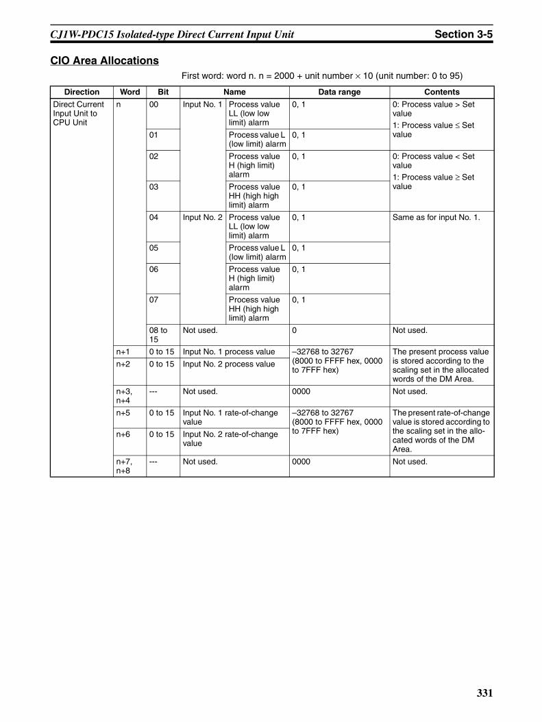
CJ1W-PDC15 Isolated-type Direct Current Input Unit Section 3-5
CIO Area AllocationsFirst word: word n. n = 2000 + unit number × 10 (unit number: 0 to 95)
Direction Word Bit Name Data range Contents
Direct Current Input Unit to CPU Unit
n 00 Input No. 1 Process value LL (low low limit) alarm
0, 1 0: Process value > Set value1: Process value ≤ Set value01 Process value L
(low limit) alarm0, 1
02 Process value H (high limit) alarm
0, 1 0: Process value < Set value1: Process value ≥ Set value03 Process value
HH (high high limit) alarm
0, 1
04 Input No. 2 Process value LL (low low limit) alarm
0, 1 Same as for input No. 1.
05 Process value L (low limit) alarm
0, 1
06 Process value H (high limit) alarm
0, 1
07 Process value HH (high high limit) alarm
0, 1
08 to 15
Not used. 0 Not used.
n+1 0 to 15 Input No. 1 process value –32768 to 32767 (8000 to FFFF hex, 0000 to 7FFF hex)
The present process value is stored according to the scaling set in the allocated words of the DM Area.
n+2 0 to 15 Input No. 2 process value
n+3, n+4
--- Not used. 0000 Not used.
n+5 0 to 15 Input No. 1 rate-of-change value
–32768 to 32767 (8000 to FFFF hex, 0000 to 7FFF hex)
The present rate-of-change value is stored according to the scaling set in the allo-cated words of the DM Area.
n+6 0 to 15 Input No. 2 rate-of-change value
n+7, n+8
--- Not used. 0000 Not used.
331

CJ1W-PDC15 Isolated-type Direct Current Input Unit Section 3-5
Note The External Power Supply Flag turns ON after external power is suppliedand the internal voltage stabilizes (which requires approximately 2 s). Theindicator on the front of the Unit will turn ON as soon as external power is sup-plied.
Direct Current Input Unit to CPU Unit, con-tinued
n+9 00 Input No. 1 Rate-of-change value L (low limit) alarm
0, 1 0: Rate-of-change value > set value
1: Rate-of-change value ≤ set value
01 Rate-of-change value H (high limit) alarm
0, 1 0: Rate-of-change value < set value1: Rate-of-change value ≥ set value
02 Input No. 2 Rate-of-change value L (low limit) alarm
0, 1 Same as for input No. 1.
03 Rate-of-change value H (high limit) alarm
04 to 07
Not used. 0 Not used.
08 Input No. 1 input error 0, 1 0: Normal1: Error (less than –17.2% or greater than 112.5%)Note Checks are con-
ducted for inputs of 4 to 20 mA and 1 to 5 V.
09 Input No. 2 input error 0, 1
10 to 12
Not used. 0 Not used.
13 Zero/span adjustment period end
0, 1 0: Adjustment enabled1: Adjustment ended
14 Zero/span adjustment period notice
0, 1 0: Adjustment enabled1: Notice period
15 External power supply 0, 1 0: External power supply not used1: External power supply used
Direction Word Bit Name Data range Contents
332

CJ1W-PDC15 Isolated-type Direct Current Input Unit Section 3-5
Expansion Control/Monitor Area AllocationsFirst word: p. p = address specified in word o+1 in the area specified by wordo in the Expansion Setting Area.
Direction Word Bit Name Data range Contents
CPU Unit to Direct Current Input Unit, continued
p 00 to 15
Not used. 0000 Not used.
p+1 00 Input No. 1 hold function selection
0, 1 0: Peak and bottom
1: Top and valley01 Input No. 2 hold function
selection0, 1
02 to 07
Not used. 0 Not used.
08 Input No. 1 hold start 0, 1 0: Do not hold.1: Hold09 Input No. 2 hold start 0, 1
10, 11 Not used. 0 Not used.
12 Input No. 1 hold value reset 0, 1 0: Normal operation
1: Reset hold value.13 Input No. 2 hold value reset 0, 1
14, 15 Not used. 0 Not used.
p+2 00 Input No. 1 integral value cal-culation start
0, 1 0: Do not start calcula-tion1: Start calculation01 Input No. 2 integral value cal-
culation start0, 1
02, 03 Not used. 0 Not used.
04 Input No. 1 integral value reset 0, 1 0: Normal operation1: Integral value reset05 Input No. 2 integral value reset 0, 1
06 to 15
Not used. 0 Not used.
p+3 00 Input No. 1 zero/span adjust-ment update bit
0, 1 0: Normal operation1: Update adjustment date(Remains ON while writing external FROM.)
01 Input No. 2 zero/span adjust-ment update bit
0, 1
02 to 15
Not used. 0 Not used.
333

CJ1W-PDC15 Isolated-type Direct Current Input Unit Section 3-5
Direct Cur-rent Input Unit to CPU Unit
p+4 00 Input No. 1
Zero/span adjustment period end
0, 1 0: Adjustment enabled.
1: Adjustment period end
01 Zero/span adjustment period notice
0, 1 0: Adjustment enabled.1: Notice period in effect.Remains set to 1 if the zero/span adjustment bit has never been ON.
02 Input No. 2
Zero/span adjustment period end
0, 1
03 Zero/span adjustment period notice
0, 1
04 to 07
Not used. 0 Not used.
08 External FROM error 0, 1 0: Normal operation.1: External FROM error.
09 to 15
Not used. 0 Not used.
p+5 00 to 15
Input No. 1
Day of final adjustment date
0100 to 3100 (BCD) Remains set to FFFF if the zero/span adjust-ment bit has never been ON.
p+6 00 to 15
Year and month of final adjustment date
0001 to 9912 (BCD)
p+7 00 to 15
Input No. 2
Day of final adjustment date
0100 to 3100 (BCD)
p+8 00 to 15
Year and month of final adjustment date
0001 to 9912 (BCD)
p+9 to p+16
00 to 15
Not used. 0000 Not used.
p+17 00 to 15
Input No. 1
Peak/top value −32728 to +32767
(8000 to FFFF hex, 0000 to 7FFF hex)
Counts the number of repetitions of condi-tional operations set in the Expansion Setting Area.
p+18 00 to 15
Bottom/valley value −32728 to +32767(8000 to FFFF hex, 0000 to 7FFF hex)
The bottom or valley value is stored accord-ing to the scaling set in the DM Area.
p+19 00 to 15
Input No. 2
Peak/top value −32728 to +32767(8000 to FFFF hex, 0000 to 7FFF hex)
Same as for Input No. 1.
p+20 00 to 15
Bottom/valley value −32728 to +32767(8000 to FFFF hex, 0000 to 7FFF hex)
p+21 to p+24
--- Not used. 0 Not used.
p+25 00 to 15
Input No. 1
Integral value (lower digit)
−2147483648 to 2147483647(80000000 to FFFFFFFF hex, 00000000 to 7FFFFFFF hex)
The integral value for the present value is stored according to the scaling set in the DM Area.
p+26 00 to 15
Integral value (upper digit)
p+27 00 to 15
Input No. 2
Integral value (lower digit)
−2147483648 to 2147483647
(80000000 to FFFFFFFF hex, 00000000 to 7FFFFFFF hex)p+28 00 to
15Integral value (upper digit)
p+29 to p+34
00 to 15
Not used. 0000 Not used.
Direction Word Bit Name Data range Contents
334

CJ1W-PDC15 Isolated-type Direct Current Input Unit Section 3-5
Terminal Connection Diagram
Voltage Inputs
Current inputs
Note • In both of the above cases, leave all unused inputs open between thepositive and negative terminals (e.g., between B2 and B3 for voltage inputNo. 1).
• Always ground the GR terminal on the Power Supply Unit of the PLC.• If the input device uses a voltage generator, temperature compensator, or
similar device, then ground the input device if it has a ground terminal. • Always short-circuit the V and I terminals when using current input.
B1 (10)
B2 (11)
B3 (12)
B4 (13)
B5 (14)
B6 (15)
B7 (16)
B8 (17)
B9 (18)
NC A1 (1)
I1 A2 (2)
NC A3 (3)
I2 A4 (4)
NC A5 (5)
NC A6 (6)
NC A7 (7)
NC A8 (8)
24V A9 (9)
NC
V1
COM1
V2
COM2
NC
NC
NC
0V
− +
− +
Voltage output device
Voltage output device
B1 (10)
B2 (11)
B3 (12)
B4 (13)
B5 (14)
B6 (15)
B7 (16)
B8 (17)
B9 (18)
NCA1 (1)
I1 A2 (2)
NCA3 (3)
I2 A4 (4)
NCA5 (5)
NCA6 (6)
NCA7 (7)
NCA8 (8)
24V A9 (9)
−
− +
+ NC
V1
COM1
V2
COM2
NC
NC
NC
0V
Current output device
Current output device
+
−
+
−
NC
V1
COM1
V2
COM2
NC
NC
NC
0V
NC
I1
NC
I2
NC
I3+
NC
I4+
24
PDC15 terminal block
Current output device
Short bars
Current output device
335

CJ1W-PDC15 Isolated-type Direct Current Input Unit Section 3-5
Terminal Block Diagram
Error Processing
Conversion Data Does Not Change.
Values are Not Converted as Intended.
Probable cause Remedy
The gain for span adjustment is set to 0.
Set the gain for span adjustment to a value other than 0.
The minimum and maximum val-ues for process value scaling are either the same or are set extremely low.
Set the minimum and maximum values correctly.
The input signal type or process value range is set incorrectly.
Check and reset the input signal type and the process value range settings.
An input device is malfunctioning, input wiring is faulty, or wiring is disconnected.
Check whether the input voltage or current has changed. Check for faulty or disconnected wir-ing.Check whether an input error has been detected in the I/O Area.
Probable cause Remedy
The input signal type or process value scaling is set incorrectly.
Check and reset the input signal type and the process value scaling settings.
The zero/span adjustment data is incorrect.
Check and correct the zero/span adjustment set-tings.
The square root function is operat-ing.
Set the square function so that it does not oper-ate.
5 VDC
B2
A2
B3
V1+
I1+
COM1
V2+
I2+
COM2
A9
B9
1 MΩ
250 Ω
B4
A4
B5
1 MΩ
250 Ω
1 MΩ
1 MΩA
mpl
ifier
ci
rcui
tA
mpl
ifier
ci
rcui
t
A/D converter
A/D converter
Isolation circuit
Photocoupler
Photocoupler
Isolation circuit
Input selector Digital
circuits
Con
nect
or
24-VDC circuit
Power supply circuit
336

CJ1W-PDC15 Isolated-type Direct Current Input Unit Section 3-5
Converted Values are Unstable.
Probable cause Remedy
Input signals are being affected by external noise.
Change the connection paths of the input signal lines. (Separate them from sources of noise or use shielded cable.)
Insert 0.01-µF to 0.1-µF ceramic capacitors between the I+ and COM input terminals.
Increase the number of values for calculating the moving average in mean value processing.
The scaling value is greater than the Unit’s resolution.
Reduce the scaling value.
337

CJ1W-PH41U Isolated-type Universal Input Unit Section 3-6
3-6 CJ1W-PH41U Isolated-type Universal Input UnitOverview
The CJ1W-PH41U Isolated-type Universal Input Unit supports four input channels, each of which can be set to a resistance thermometer, thermocou-ple, DC signal, or potentiometer input. All inputs are isolated.
CJ1W-PH41U
System Configuration
Features• A single Unit supports a maximum of four inputs: resistance thermometer,
thermocouple, DC current/voltage, and potentiometer. The input type isset separately for each input. Resistance thermometer input Pt100 (JIS, IEC 3-wire), JPt100 (3-wire),Pt1000 (3-wire), or Pt100 (JIS, IEC 4-wire) can be selected.Thermocouple input K, J, T, E, L, U, N, R, S, B, WRe5-26, or PLII can beselected.For DC signal, 4 to 20 mA, 0 to 20 mA, 1 to 5 V, 0 to 1.25 V, 0 to 5 V, 0 to10 V, ±100 mV, −1.25 to 1.25 V, −5 to 5 V, or −10 to 10 V can be selected.In addition, a potentiometer input can be selected.
• Isolation between input channels prevents unwanted current pathsbetween input channels.
• A minimum resolution of 1/256,000 is achieved.• The conversion period is 60 ms/4 points at a resolution of 1/256,000,
10 ms/4 points at 1/64,000 (Pt1000 or a potentiometer input cannot be
PH41U
MACH
No.10
1
100
RUNERCERH
W
O
C
mA V ±100 mV
Resistance thermometer input:Pt100 (3-wire), JPt100 (3-wire)Pt1000 (3-wire), Pt100 (4-wire)
Thermocouple input:K, J, T, E, L, U, N, R, S, B, WRe5-26, PLII
DC input:4 to 20 mA, 0 to 20 mA
DC voltage input:1 to 5 V, 0 to 1.25 V, 0 to 5 V, 0 to 10 V, ±100 mV, −1.25 to 1.25 V, −5 to 5 V, −10 to 10 V
Potentiometer input
CJ1W-PH41U
Channel 1
Channel 2
Channel 3
Channel 4
Isolation
Isolation
Isolation
338

CJ1W-PH41U Isolated-type Universal Input Unit Section 3-6
selected), and 5 ms/4 points at 1/16,000 (K and E thermocouple inputsonly can be selected). The fastest conversion period is automatically setfor the resolution.
• Scaled values are transferred to the CPU Unit in eight or four digits hexa-decimal.
• Input ranges can be set to any values.• Process value alarms (four alarms for each point) are provided.• Alarm ON/OFF delay timer and hysteresis are provided for process val-
ues.• Averaging function is provided. • Rate-of-change function is provided.• Rate-of-change alarms (two alarms for each point) are provided.• Zero/span adjustment during operation is supported.• Input error detection is supported. • Process value clamp direction is supported for input burnout.• Adjustment period control is provided. • Peak and bottom value detection is supported. • Top and valley value detection is supported. • Square root extraction (DC input only) is supported. • Integral value calculation is supported.
Model InformationType of
UnitModel Number of
inputsInput types
CJ-series Special I/O Unit
CJ1W-PH41U 4 Resistance thermometer: Pt100 (JIS, IEC 3-wire), JPt100 (3-wire), Pt1000 (3-wire), Pt100 (JIS, IEC 4-wire)
Thermocouple: K, J, T, E, L, U, N, R, S, B, WRe5-26, PLIICurrent: 4 to 20 mA, 0 to 20 mA
Voltage: 1 to 5 V, 0 to 1.25 V, 0 to 5 V, 0 to 10 V, ±100 mV, −1.25 to 1.25 V, −5 to 5 V, −10 to 10 V
Potentiometer: The input type is set separately for each input.
339

CJ1W-PH41U Isolated-type Universal Input Unit Section 3-6
Block Diagram (Order of Processing)
CIO Area
CPU Unit
HH, H, L, LL
Process value Process value alarm
Peak/bottom value Top/valley value
Output limit: −15% to 115%
H, L
Input error alarm
I/O refresh
Input error: 115% or −15%
Output limit: −15% to 115%
Offset compensation
Input error check
Process value scaling
Zero/span adjustment
Input calculations:• Input range• Cold junction temperature compensation (thermocouple input only)
A/D conversion, moving average
Expansion Control/Monitor Area
Rate-of-change value
Rate-of-change alarmCold junction sensor error
Isolated-type Universal Input Unit
Process value alarm
Rate-of-change alarm
Rate-of-change calculation and scaling
Square root (DC input only)
Thermocouple input only
Cold junction sensor
Resistance thermometer, thermocouple, DC input, or potentiometer
340
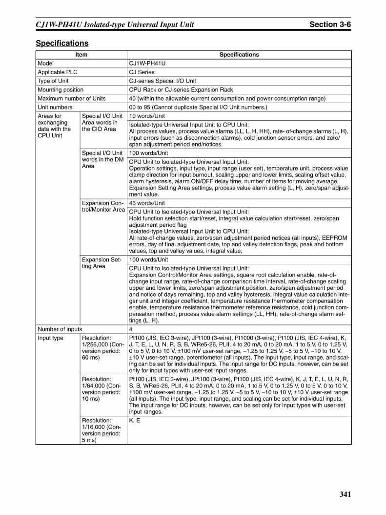
CJ1W-PH41U Isolated-type Universal Input Unit Section 3-6
SpecificationsItem Specifications
Model CJ1W-PH41U
Applicable PLC CJ Series
Type of Unit CJ-series Special I/O Unit
Mounting position CPU Rack or CJ-series Expansion Rack
Maximum number of Units 40 (within the allowable current consumption and power consumption range)
Unit numbers 00 to 95 (Cannot duplicate Special I/O Unit numbers.)
Areas for exchanging data with the CPU Unit
Special I/O Unit Area words in the CIO Area
10 words/Unit
Isolated-type Universal Input Unit to CPU Unit:All process values, process value alarms (LL, L, H, HH), rate- of-change alarms (L, H), input errors (such as disconnection alarms), cold junction sensor errors, and zero/span adjustment period end/notices.
Special I/O Unit words in the DM Area
100 words/Unit
CPU Unit to Isolated-type Universal Input Unit:Operation settings, input type, input range (user set), temperature unit, process value clamp direction for input burnout, scaling upper and lower limits, scaling offset value, alarm hysteresis, alarm ON/OFF delay time, number of items for moving average, Expansion Setting Area settings, process value alarm setting (L, H), zero/span adjust-ment value.
Expansion Con-trol/Monitor Area
46 words/Unit
CPU Unit to Isolated-type Universal Input Unit:Hold function selection start/reset, integral value calculation start/reset, zero/span adjustment period flagIsolated-type Universal Input Unit to CPU Unit: All rate-of-change values, zero/span adjustment period notices (all inputs), EEPROM errors, day of final adjustment date, top and valley detection flags, peak and bottom values, top and valley values, integral value.
Expansion Set-ting Area
100 words/Unit
CPU Unit to Isolated-type Universal Input Unit:Expansion Control/Monitor Area settings, square root calculation enable, rate-of-change input range, rate-of-change comparison time interval, rate-of-change scaling upper and lower limits, zero/span adjustment position, zero/span adjustment period and notice of days remaining, top and valley hysteresis, integral value calculation inte-ger unit and integer coefficient, temperature resistance thermometer compensation enable, temperature resistance thermometer reference resistance, cold junction com-pensation method, process value alarm settings (LL, HH), rate-of-change alarm set-tings (L, H).
Number of inputs 4
Input type Resolution: 1/256,000 (Con-version period: 60 ms)
Pt100 (JIS, IEC 3-wire), JPt100 (3-wire), Pt1000 (3-wire), Pt100 (JIS, IEC 4-wire), K, J, T, E, L, U, N, R, S, B, WRe5-26, PLII, 4 to 20 mA, 0 to 20 mA, 1 to 5 V, 0 to 1.25 V, 0 to 5 V, 0 to 10 V, ±100 mV user-set range, −1.25 to 1.25 V, −5 to 5 V, −10 to 10 V, ±10 V user-set range, potentiometer (all inputs). The input type, input range, and scal-ing can be set for individual inputs. The input range for DC inputs, however, can be set only for input types with user-set input ranges.
Resolution: 1/64,000 (Con-version period: 10 ms)
Pt100 (JIS, IEC 3-wire), JPt100 (3-wire), Pt100 (JIS, IEC 4-wire), K, J, T, E, L, U, N, R, S, B, WRe5-26, PLII, 4 to 20 mA, 0 to 20 mA, 1 to 5 V, 0 to 1.25 V, 0 to 5 V, 0 to 10 V, ±100 mV user-set range, −1.25 to 1.25 V, −5 to 5 V, −10 to 10 V, ±10 V user-set range (all inputs). The input type, input range, and scaling can be set for individual inputs. The input range for DC inputs, however, can be set only for input types with user-set input ranges.
Resolution: 1/16,000 (Con-version period: 5 ms)
K, E
341

CJ1W-PH41U Isolated-type Universal Input Unit Section 3-6
Applicable standards for resis-tance thermometer and thermo-couple inputs
Pt100: JIS C1604-1997, IEC 60751-95JPt100: JIS C1604-1989K, J, T, E, N, R, S, B: JIS C1602-1995L, U: DIN 43710-1985WRe5-26: ASTM E988-96PLII: ASTM E1751-00
Scaling Data to be stored in the allocated words in the CIO area must be scaled (with user-set minimum and maximum values for data and offsets). The inputs are set individually. Data can be converted at 0% to 100%.
Data storage in the Special I/O Unit Area in the CIO Area
The values derived from carrying out the following processing in order of the actual process data in the input range are stored in four digits hexadecimal (binary values) in the allocated words in the Special I/O Unit Area.1) Averaging → 2) Scaling → 3) Zero/span adjustment → 4) Square root calculation → 5) Offset compensation → 6) Output limits
Accuracy (25°C) Resistance thermometer or thermocouple input: ±0.05% (The accuracy depends on the input type and the measured tempera-ture. For details, refer to the Accuracy and Temperature Coefficient According to Resistance Thermometer and Thermocouple Input Types and Measured Temper-atures on page 347.
Current or voltage input: ±0.05%Potentiometer input: ±1%
Temperature coefficient Resistance thermometer or thermocouple input:The temperature coefficient depends on the input type and the measured temper-ature. For details, refer to the Accuracy and Temperature Coefficient According to Resistance Thermometer and Thermocouple Input Types and Measured Temper-atures on page 347.
Current or voltage input: ±80 ppm/°C (for full scale)
Potentiometer input: ±100 ppm/°C (for full scale)
Cold junction compensation error Thermocouple input: ±1.2°CResolution 1/256,000 (Conversion period: 60 ms) (See note.), 1/64,000 (Conversion period:
10 ms), 1/16,000 (Conversion period: 5 ms)
Note: The resolution for a potentiometer input is 1/4,000.
Input signal range Resistance thermometer, thermocouple, ±100 mV user-set input:−15% to 115% of measurable input range
4 to 20 mA, 1 to 5 V, 0 to 1.25 V, 0 to 5 V, 0 to 10 V input: −15% to 115%
0 to 20 mA input:0% to 115%
−1.25 to 1.25 V, −5 to 5 V, −10 to 10 V, ±10 V user-set range input:−7.5% to 107.5%
Potentiometer input: −15% to 115% of 0 to 2,500 Ω
Influence of lead wire resistance Resistance thermometer input: 0.06°C/Ω (20 Ω max.) (3-wire)0.006°C/Ω (20 Ω max.) (4-wire)
Input detection current Resistance thermometer input: Approx. 0.21 mA (3-wire), approx. 0.42 mA (4-wire)Potentiometer input: Approx. 0.21 mA
Absolute maximum ratings Thermocouple, ±100 mV user-set range input: ±130 mVCurrent input: 30 mAVoltage input (excluding ±100 mV user-set range): ±15 V
Input impedance Thermocouple, ±100 mV user-set range input: 20 kΩ min.Current input: 150 Ω max.Voltage input (excluding ±100 mV user-set range): 1 MΩ min.
Input disconnection detection cur-rent
Thermocouple, ±100 mV user-set range input: Approx. 0.1 µA
Item Specifications
342
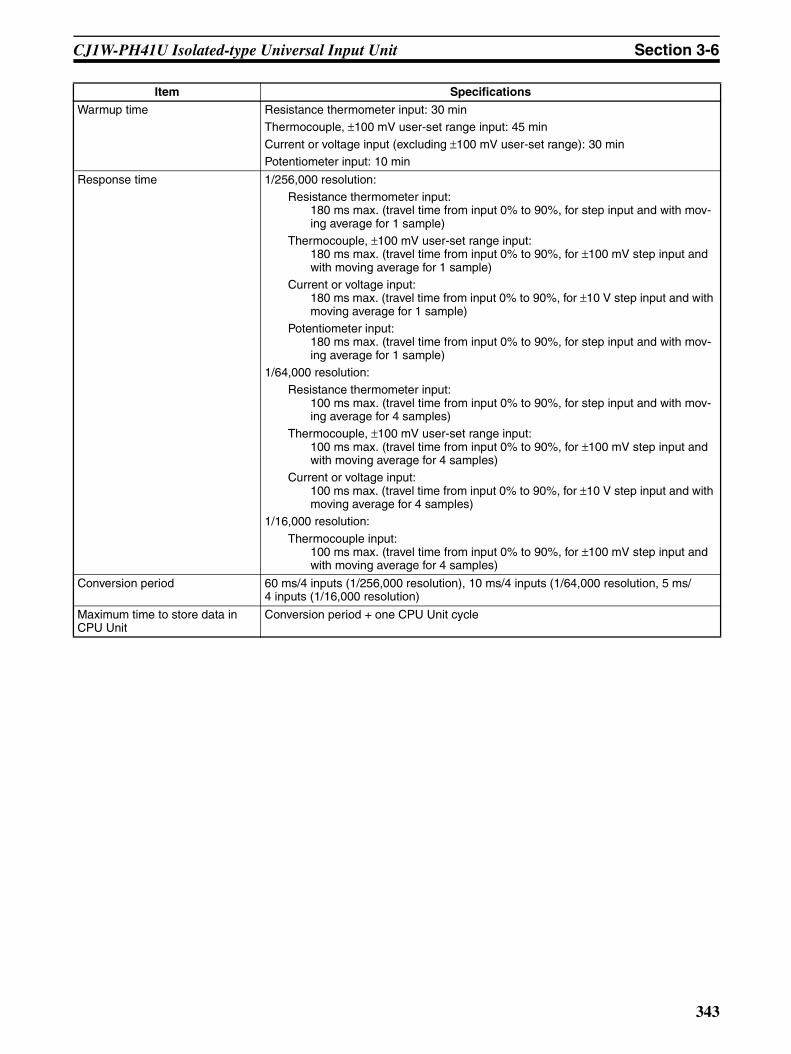
CJ1W-PH41U Isolated-type Universal Input Unit Section 3-6
Warmup time Resistance thermometer input: 30 minThermocouple, ±100 mV user-set range input: 45 min
Current or voltage input (excluding ±100 mV user-set range): 30 minPotentiometer input: 10 min
Response time 1/256,000 resolution:Resistance thermometer input:
180 ms max. (travel time from input 0% to 90%, for step input and with mov-ing average for 1 sample)
Thermocouple, ±100 mV user-set range input:180 ms max. (travel time from input 0% to 90%, for ±100 mV step input and with moving average for 1 sample)
Current or voltage input:180 ms max. (travel time from input 0% to 90%, for ±10 V step input and with moving average for 1 sample)
Potentiometer input:180 ms max. (travel time from input 0% to 90%, for step input and with mov-ing average for 1 sample)
1/64,000 resolution:Resistance thermometer input:
100 ms max. (travel time from input 0% to 90%, for step input and with mov-ing average for 4 samples)
Thermocouple, ±100 mV user-set range input:100 ms max. (travel time from input 0% to 90%, for ±100 mV step input and with moving average for 4 samples)
Current or voltage input:100 ms max. (travel time from input 0% to 90%, for ±10 V step input and with moving average for 4 samples)
1/16,000 resolution:
Thermocouple input:100 ms max. (travel time from input 0% to 90%, for ±100 mV step input and with moving average for 4 samples)
Conversion period 60 ms/4 inputs (1/256,000 resolution), 10 ms/4 inputs (1/64,000 resolution, 5 ms/4 inputs (1/16,000 resolution)
Maximum time to store data in CPU Unit
Conversion period + one CPU Unit cycle
Item Specifications
343

CJ1W-PH41U Isolated-type Universal Input Unit Section 3-6
Input disconnection and input error detection
Resistance thermometer, thermocouple, ±100 mV user-set range, potentiometer input:
Input Error Flag turns ON when a disconnection occurs or when 115% or −15% of the measurable input range is exceeded. The process value clamp direct direction for when a disconnection occurs can be specified. (High: 115% of set input range. Low: −15% of set input range.)Disconnection detection time:
Approx. 5 s max. (4-wire Pt100)Approx. 1 s max. (±100 mV user-set range)Approx. 0.5 s max. (not 4-wire Pt100 or ±100 mV user-set range)
4 to 20 mA, 1 to 5 V, 0 to 1.25 V, 0 to 5 V, 0 to 10 V input:
An error is detected and the Input Error Flag turns ON when a disconnection occurs or when 115% or −15% of the measurable input range is exceeded.When a disconnection occurs in the 4 to 20 mA/1 to 5 V range, the −15% process value is stored. When a disconnection occurs in any other range, a process value the same as for a 0 V input is stored.
0 to 20 mA input:
An error is detected and the Input Error Flag turns ON when 115% of the measur-able input range is exceeded. When a disconnection occurs, a process value the same as for a 0 mA input is stored.
−1.25 to 1.25 V, −5 to 5 V,−10 to 10 V, ±10 V user-set range input: An error is detected and the Input Error Flag turns ON when 107.5% or −7.5% of the measurable input range is exceeded. When a disconnection occurs, a process value the same as for a 0 V input is stored.
Item Specifications
344
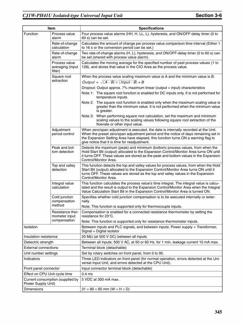
CJ1W-PH41U Isolated-type Universal Input Unit Section 3-6
Function Process value alarm
Four process value alarms (HH, H, LL, L), hysteresis, and ON/OFF-delay timer (0 to 60 s) can be set.
Rate-of-change calculation
Calculates the amount of change per process value comparison time interval (Either 1 to 16 s or the conversion period can be set.)
Rate-of-change alarm
Two rate-of-change alarms (H, L), hysteresis, and ON/OFF-delay timer (0 to 60 s) can be set (shared with process value alarm).
Process value averaging (input filter)
Calculates the moving average for the specified number of past process values (1 to 128), and stores that value in the CIO Area as the process value.
Square root extraction
When the process value scaling maximum value is A and the minimum value is B:
Dropout: Output approx. 7% maximum linear (output = input) characteristicsNote 1: The square root function is enabled for DC inputs only. It is not performed for
temperature inputs.Note 2: The square root function is enabled only when the maximum scaling value is
greater than the minimum value. It is not performed when the minimum value is greater.
Note 3: When performing square root calculation, set the maximum and minimum scaling values to the scaling values following square root extraction of the flowrate or other input value.
Adjustment period control
When zero/span adjustment is executed, the date is internally recorded at the Unit. When the preset zero/span adjustment period and the notice of days remaining set in the Expansion Setting Area have elapsed, this function turns ON a warning flag to give notice that it is time for readjustment.
Peak and bot-tom detection
Detects the maximum (peak) and minimum (bottom) process values, from when the Hold Start Bit (output) allocated to the Expansion Control/Monitor Area turns ON until it turns OFF. These values are stored as the peak and bottom values in the Expansion Control/Monitor Area.
Top and valley detection
This function detects the top and valley values for process values, from when the Hold Start Bit (output) allocated to the Expansion Control/Monitor Area turns ON until it turns OFF. These values are stored as the top and valley values in the Expansion Control/Monitor Area.
Integral value calculation
This function calculates the process value's time integral. The integral value is calcu-lated and the result is output to the Expansion Control/Monitor Area when the Integral Value Calculation Start Bit in the Expansion Control/Monitor Area is turned ON.
Cold junction compensation method
Specifies whether cold junction compensation is to be executed internally or exter-nally.
Note: This function is supported only for thermocouple inputs.
Resistance ther-mometer input compensation
Compensation is enabled for a connected resistance thermometer by setting the resistance for 23°C.
Note: This function is supported only for resistance thermometer inputs.
Isolation Between inputs and PLC signals, and between inputs: Power supply = Transformer, Signal = Digital isolator
Insulation resistance 20 MΩ (at 500 V DC) between all inputs
Dielectric strength Between all inputs: 500 V AC, at 50 or 60 Hz, for 1 min, leakage current 10 mA max.
External connections Terminal block (detachable)
Unit number settings Set by rotary switches on front panel, from 0 to 95.
Indicators Three LED indicators on front panel (for normal operation, errors detected at the Uni-versal Input Unit, and errors detected at the CPU Unit).
Front panel connector Input connector terminal block (detachable)
Effect on CPU Unit cycle time 0.4 ms
Current consumption (supplied by Power Supply Unit)
5 VDC at 300 mA max.
Dimensions 31 × 90 × 65 mm (W × H × D)
Item Specifications
Output A B–⟨ ⟩ Input B–⟨ ⟩× B+=
345
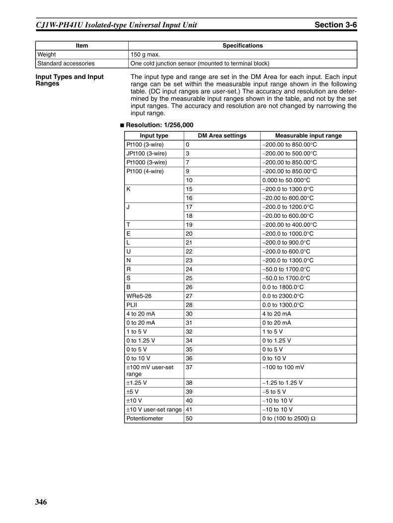
CJ1W-PH41U Isolated-type Universal Input Unit Section 3-6
Input Types and Input Ranges
The input type and range are set in the DM Area for each input. Each inputrange can be set within the measurable input range shown in the followingtable. (DC input ranges are user-set.) The accuracy and resolution are deter-mined by the measurable input ranges shown in the table, and not by the setinput ranges. The accuracy and resolution are not changed by narrowing theinput range.
Resolution: 1/256,000
Weight 150 g max.
Standard accessories One cold junction sensor (mounted to terminal block)
Item Specifications
Input type DM Area settings Measurable input range
Pt100 (3-wire) 0 −200.00 to 850.00°CJPt100 (3-wire) 3 −200.00 to 500.00°CPt1000 (3-wire) 7 −200.00 to 850.00°CPt100 (4-wire) 9 −200.00 to 850.00°C
10 0.000 to 50.000°CK 15 −200.0 to 1300.0°C
16 −20.00 to 600.00°CJ 17 −200.0 to 1200.0°C
18 −20.00 to 600.00°CT 19 −200.00 to 400.00°CE 20 −200.0 to 1000.0°CL 21 −200.0 to 900.0°CU 22 −200.0 to 600.0°CN 23 −200.0 to 1300.0°CR 24 −50.0 to 1700.0°CS 25 −50.0 to 1700.0°CB 26 0.0 to 1800.0°CWRe5-26 27 0.0 to 2300.0°CPLII 28 0.0 to 1300.0°C4 to 20 mA 30 4 to 20 mA
0 to 20 mA 31 0 to 20 mA
1 to 5 V 32 1 to 5 V
0 to 1.25 V 34 0 to 1.25 V
0 to 5 V 35 0 to 5 V
0 to 10 V 36 0 to 10 V
±100 mV user-set range
37 −100 to 100 mV
±1.25 V 38 −1.25 to 1.25 V
±5 V 39 −5 to 5 V
±10 V 40 −10 to 10 V
±10 V user-set range 41 −10 to 10 V
Potentiometer 50 0 to (100 to 2500) Ω
346
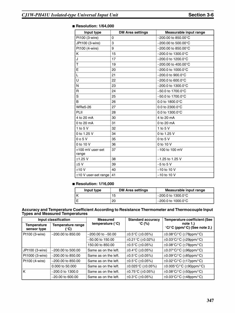
CJ1W-PH41U Isolated-type Universal Input Unit Section 3-6
Resolution: 1/64,000
Resolution: 1/16,000
Accuracy and Temperature Coefficient According to Resistance Thermometer and Thermocouple Input Types and Measured Temperatures
Input type DM Area settings Measurable input range
Pt100 (3-wire) 0 −200.00 to 850.00°CJPt100 (3-wire) 3 −200.00 to 500.00°CPt100 (4-wire) 9 −200.00 to 850.00°CK 15 −200.0 to 1300.0°CJ 17 −200.0 to 1200.0°CT 19 −200.00 to 400.00°CE 20 −200.0 to 1000.0°CL 21 −200.0 to 900.0°CU 22 −200.0 to 600.0°CN 23 −200.0 to 1300.0°CR 24 −50.0 to 1700.0°CS 25 −50.0 to 1700.0°CB 26 0.0 to 1800.0°CWRe5-26 27 0.0 to 2300.0°CPLII 28 0.0 to 1300.0°C4 to 20 mA 30 4 to 20 mA
0 to 20 mA 31 0 to 20 mA
1 to 5 V 32 1 to 5 V
0 to 1.25 V 34 0 to 1.25 V
0 o 5 V 35 0 to 5 V
0 to 10 V 36 0 to 10 V
±100 mV user-set range
37 −100 to 100 mV
±1.25 V 38 −1.25 to 1.25 V
±5 V 39 −5 to 5 V
±10 V 40 −10 to 10 V
±10 V user-set range 41 −10 to 10 V
Input type DM Area settings Measurable input range
K 15 −200.0 to 1300.0°CE 20 −200.0 to 1000.0°C
Input classification Measured temperature (°C)
Standard accuracy°C (%)
Temperature coefficient (See note 1.)
°C/°C (ppm/°C) (See note 2.)Temperature sensor type
Temperature range (°C)
Pt100 (3-wire) −200.00 to 850.00 −200.00 to −50.00 ±0.5°C (±0.05%) ±0.08°C/°C (±78ppm/°C)
−50.00 to 150.00 ±0.21°C (±0.02%) ±0.03°C/°C (±29ppm/°C)
150.00 to 850.00 ±0.5°C (±0.05%) ±0.08°C/°C (±78ppm/°C)
JPt100 (3-wire) −200.00 to 500.00 Same as on the left. ±0.4°C (±0.05%) ±0.07°C/°C (±96ppm/°C)
Pt1000 (3-wire) −200.00 to 850.00 Same as on the left. ±0.5°C (±0.05%) ±0.09°C/°C (±85ppm/°C)
Pt100 (4-wire) −200.00 to 850.00 Same as on the left. ±0.5°C (±0.05%) ±0.02°C/°C (±17ppm/°C)
0.000 to 50.000 Same as on the left. ±0.025°C (±0.05%) ±0.005°C/°C (±90ppm/°C)
K −200.0 to 1300.0 Same as on the left. ±0.75°C (±0.05%) ±0.08°C/°C (±50ppm/°C)
−20.00 to 600.00 Same as on the left. ±0.3°C (±0.05%) ±0.03°C/°C (±48ppm/°C)
347

CJ1W-PH41U Isolated-type Universal Input Unit Section 3-6
Note 1. Error in process value when ambient temperature changes by 1°C.
2. For full-scale.
J −200.0 to 1200.0 −200.0 to 0.0 ±0.7°C (±0.05%) ±0.13°C/°C (±96ppm/°C)
0.0 to 1200.0 ±0.06°C/°C (±42ppm/°C)
−20.00 to 600.00 Same as on the left. ±0.3°C (±0.05%) ±0.04°C/°C (±72ppm/°C)
T −200.00 to 400.00 −200.00 to −180.00 ±1.3°C (±0.22%) ±0.05°C/°C (±75ppm/°C)
−180.00 to 0.00 ±0.7°C (±0.12%)
0.00 to 400.00 ±0.33°C (±0.055%)
E −200.0 to 1000.0 −200.0 to 0.0 ±0.6°C (±0.05%) ±0.12°C/°C (±100ppm/°C)
0.0 to 1000.0 ±0.06°C/°C (±50ppm/°C)
L −200.0 to 900.0 Same as on the left. ±0.5°C (±0.05%) ±0.04°C/°C (±40ppm/°C)
U −200.0 to 600.0 −200.0 to −100.0 ±0.7°C (±0.09%) ±0.06°C/°C (±75ppm/°C)
−100.0 to 0.0 ±0.5°C (±0.07%)
0.0 to 600.0 ±0.4°C (±0.05%)
N −200.0 to 1300.0 −200.0 to −150.0 ±1.6°C (±0.11%) ±0.11°C/°C (±70ppm/°C)
−150.0 to −100.0 ±0.75°C (±0.05%)
−100.0 to 1300.0 ±0.08°C/°C (±50ppm/°C)
R −50.0 to 1700.0 −50.0 to 0.0 ±3.2°C (±0.19%) ±0.13°C/°C (±77ppm/°C)
0.0 to 100.0 ±2.5°C (±0.15%) ±0.11°C/°C (±60ppm/°C)
100.0 to 1700.0 ±1.75°C (±0.1%)
S −50.0 to 1700.0 −50.0 to 0.0 ±3.2°C (±0.19%) ±0.13°C/°C (±77ppm/°C)
0.0 to 100.0 ±2.5°C (±0.15%) ±0.11°C/°C (±60ppm/°C)
100.0 to 1700.0 ±1.75°C (±0.1%)
B 0.0 to 1800.0 0.0 to 400.0 May not be accurate. May not be accurate.
400.0 to 800.0 ±3°C (±0.17%) ±0.12°C/°C (±66ppm/°C)
800.0 to 1800.0 ±1.8°C (±0.1%)
WRe5-26 0.0 to 2300.0 0.0 to 1500.0 ±1.15°C (±0.05%) ±0.13°C/°C (±58ppm/°C)
1500.0 to 2200.0 ±0.21°C/°C (±91ppm/°C)
2200.0 to 2300.0 ±1.4°C (±0.07%)
PLII 0.0 to 1300.0 Same as on the left. ±0.65°C (±0.05%) ±0.07°C/°C (±57ppm/°C)
Input classification Measured temperature (°C)
Standard accuracy°C (%)
Temperature coefficient (See note 1.)
°C/°C (ppm/°C) (See note 2.)Temperature sensor type
Temperature range (°C)
348

CJ1W-PH41U Isolated-type Universal Input Unit Section 3-6
DM Area AllocationsFirst word: word m. m = D20000 + unit number × 100 (unit number: 0 to 95)
DM Area address Data range Default Data contents
Input No. 1
Input No. 2
Input No. 3
Input No. 4
Decimal Hexadecimal
m 12345, 0 3039 hex, 0000 hex 0 (0000 hex) Default Block Read Command Specifies the direction of data trans-fer when the PLC is turned ON or the Unit is restarted.• 12345 (3039 hex): The initial set-
tings for the Analog I/O Unit aretransferred from the Analog I/OUnit to words m+1 to m+93 in theCPU Unit. When the transfer iscompleted, the value will become0000 hex.
• Other than 12345 (3039 hex),such as 0 (0000 hex): The data inthe allocated words of DM Area istransferred from the CPU Unit tothe Analog Input Unit.
Operation Settings (See note 1.)
m+1 (See note 1.) (See note 1.) 0 (0000 hex) Bits 00 to 03: Resolution SwitchBits 04 to 07: Process Value Data Length
Setting Group 1 (continuously refreshed area): Parameters that are continuously refreshed during PLC operation (can be set regardless of the CPU Unit's operation mode)
Process value alarm settings
m+2 m+10 m+18 m+26 −2147483648 to 2147483647
80000000 to FFFFFFFF hex, 00000000 to 7FFFFFFF hex
40000 (00009C40 hex)
Lower Process Value H (High Limit) Alarm Setting (Set to process value scal-ing value.)
m+3 m+11 m+19 m+27 Upper
m+4 m+12 m+20 m+28 −2147483648 to 2147483647
80000000 to FFFFFFFF hex, 00000000 to 7FFFFFFF hex
0 (00000000 hex)
Lower Process Value L (Low Limit) Alarm Setting (Set to process value scal-ing value.)
m+5 m+13 m+21 m+29 Upper
Zero/span adjustment
m+6 m+14 m+22 m+30 1 to 100000000
00000001 to 05F5E100 hex
10000000 (00989680 hex)
Lower Gain for Span Adjust-ment (set value × 0.0000001% (10−7)%)
m+7 m+15 m+23 m+31 Upper
m+8 m+16 m+24 m+32 −2147483648 to 2147483647
80000000 to FFFFFFFF hex, 00000000 to 7FFFFFFF hex
0 (00000000 hex)
Lower Zero Adjustment Value (Set to process value scaling value.)
m+9 m+17 m+25 m+33 Upper
349
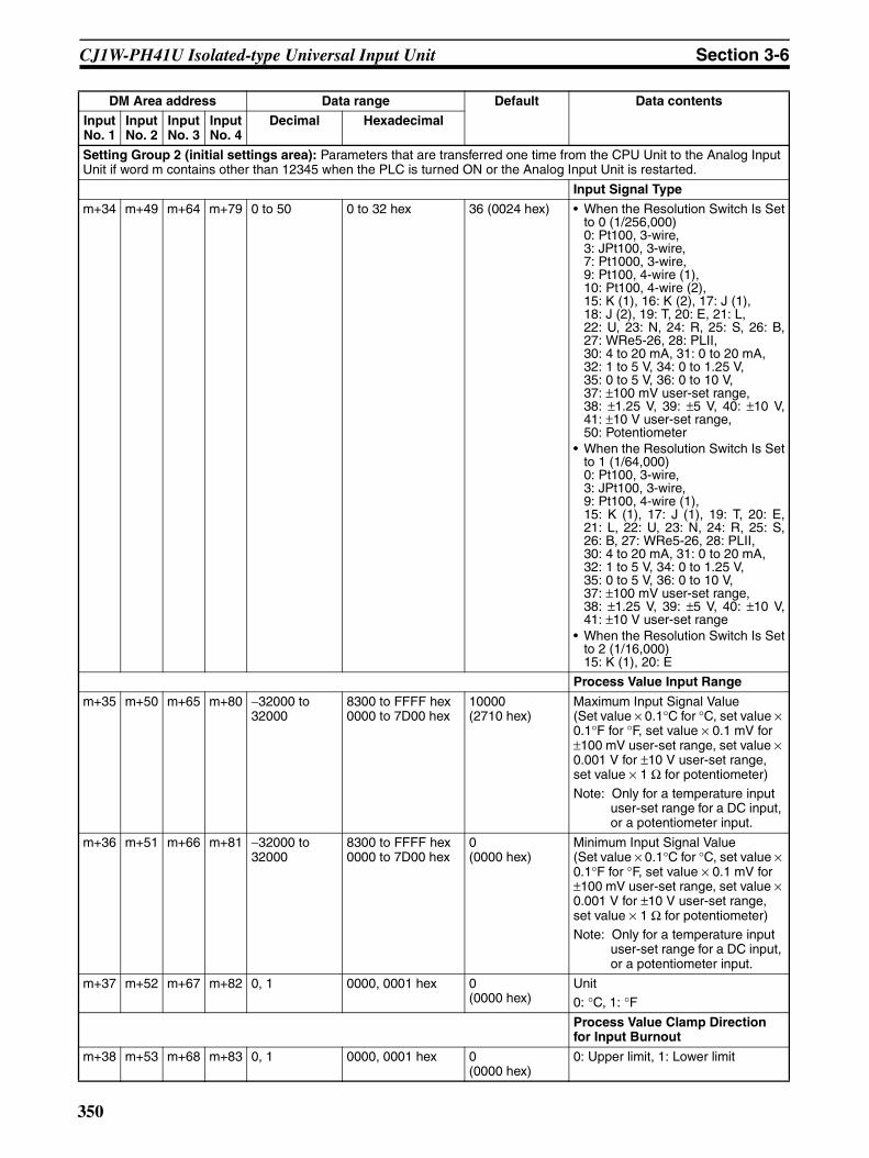
CJ1W-PH41U Isolated-type Universal Input Unit Section 3-6
Setting Group 2 (initial settings area): Parameters that are transferred one time from the CPU Unit to the Analog Input Unit if word m contains other than 12345 when the PLC is turned ON or the Analog Input Unit is restarted.
Input Signal Type
m+34 m+49 m+64 m+79 0 to 50 0 to 32 hex 36 (0024 hex) • When the Resolution Switch Is Setto 0 (1/256,000)0: Pt100, 3-wire, 3: JPt100, 3-wire, 7: Pt1000, 3-wire, 9: Pt100, 4-wire (1), 10: Pt100, 4-wire (2), 15: K (1), 16: K (2), 17: J (1), 18: J (2), 19: T, 20: E, 21: L, 22: U, 23: N, 24: R, 25: S, 26: B,27: WRe5-26, 28: PLII, 30: 4 to 20 mA, 31: 0 to 20 mA, 32: 1 to 5 V, 34: 0 to 1.25 V, 35: 0 to 5 V, 36: 0 to 10 V, 37: ±100 mV user-set range, 38: ±1.25 V, 39: ±5 V, 40: ±10 V,41: ±10 V user-set range, 50: Potentiometer
• When the Resolution Switch Is Setto 1 (1/64,000)0: Pt100, 3-wire, 3: JPt100, 3-wire, 9: Pt100, 4-wire (1), 15: K (1), 17: J (1), 19: T, 20: E,21: L, 22: U, 23: N, 24: R, 25: S,26: B, 27: WRe5-26, 28: PLII, 30: 4 to 20 mA, 31: 0 to 20 mA, 32: 1 to 5 V, 34: 0 to 1.25 V, 35: 0 to 5 V, 36: 0 to 10 V, 37: ±100 mV user-set range, 38: ±1.25 V, 39: ±5 V, 40: ±10 V,41: ±10 V user-set range
• When the Resolution Switch Is Setto 2 (1/16,000)15: K (1), 20: E
Process Value Input Range
m+35 m+50 m+65 m+80 −32000 to 32000
8300 to FFFF hex 0000 to 7D00 hex
10000 (2710 hex)
Maximum Input Signal Value(Set value × 0.1°C for °C, set value × 0.1°F for °F, set value × 0.1 mV for ±100 mV user-set range, set value × 0.001 V for ±10 V user-set range, set value × 1 Ω for potentiometer)
Note: Only for a temperature input user-set range for a DC input, or a potentiometer input.
m+36 m+51 m+66 m+81 −32000 to 32000
8300 to FFFF hex 0000 to 7D00 hex
0 (0000 hex)
Minimum Input Signal Value(Set value × 0.1°C for °C, set value × 0.1°F for °F, set value × 0.1 mV for ±100 mV user-set range, set value × 0.001 V for ±10 V user-set range, set value × 1 Ω for potentiometer)Note: Only for a temperature input
user-set range for a DC input, or a potentiometer input.
m+37 m+52 m+67 m+82 0, 1 0000, 0001 hex 0 (0000 hex)
Unit0: °C, 1: °FProcess Value Clamp Direction for Input Burnout
m+38 m+53 m+68 m+83 0, 1 0000, 0001 hex 0 (0000 hex)
0: Upper limit, 1: Lower limit
DM Area address Data range Default Data contents
Input No. 1
Input No. 2
Input No. 3
Input No. 4
Decimal Hexadecimal
350

CJ1W-PH41U Isolated-type Universal Input Unit Section 3-6
Process Value Scaling
m+39 m+54 m+69 m+84 −2147483648 to 2147483647
80000000 to FFFFFFFF hex, 00000000 to 7FFFFFFF hex
10000 (00002710 hex)
Lower Value Stored for Maxi-mum Value in Range (Span)
m+40 m+55 m+70 m+85 Upper
m+41 m+56 m+71 m+86 −2147483648 to 2147483647
80000000 to FFFFFFFF hex, 00000000 to 7FFFFFFF hex
0 (00000000 hex)
Lower Value Stored for Mini-mum Value in Range (Zero)
m+42 m+57 m+72 m+87 Upper
m+43 m+58 m+73 m+88 −2147483648 to 2147483647
80000000 to FFFFFFFF hex, 00000000 to 7FFFFFFF hex
0 (00000000 hex)
Lower Scaling Offset
m+44 m+59 m+74 m+89 Upper
Alarm Supplementary Functions
m+45 m+60 m+75 m+90 0 to 32767 0000 to 7FFF hex 40 (0028 hex)
Alarm Hysteresis(Set to process value scaling value. Shared with process value alarm and rate-of-change alarm.)
m+46 m+61 m+76 m+91 0 to 60 0000 to 003C hex 0 (0000 hex)
Alarm ON-delay Time (Unit: s)(Shared with process value alarm and rate-of-change alarm.)
m+47 m+62 m+77 m+92 0 to 60 0000 to 003C hex 0 (0000 hex)
Alarm OFF-delay Time (Unit: s) (Shared with process value alarm and rate-of-change alarm.)
Mean Value Processing Function
m+48 m+63 m+78 m+93 0 to 128 0000 to 0080 hex 0 (0000 hex)
Number of Process Values for Cal-culating Moving Average for Mean Value Processing0: 4 values for a resolution of
1/256,000, 25 values for a reso-lution of 1/64,000 or 1/16,000
1 to 128: Number of process values
Display parameter
m+94 m+95 m+96 m+97 0 to 99, 100 to 1XX
0000 to 0063 hex, 0064 to 0XXX hex
0 (0000 hex)
Address of Data Range Error (See note 2.)
Expansion Setting Area Allocation Settings
m+98 0 to 5 0000 to 0005 hex --- Area of Expansion Setting Area
0: Not used; 1: DM; 2: CIO; 3: W; 4: H; 5: EM
m+99 0 to 32767 0000 to 7FFF hex --- First Word in Expansion Setting Area
DM Area address Data range Default Data contents
Input No. 1
Input No. 2
Input No. 3
Input No. 4
Decimal Hexadecimal
351
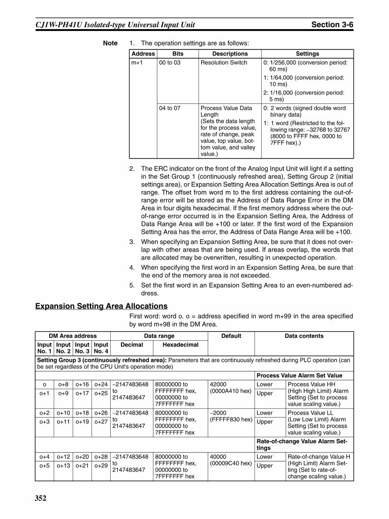
CJ1W-PH41U Isolated-type Universal Input Unit Section 3-6
Note 1. The operation settings are as follows:
2. The ERC indicator on the front of the Analog Input Unit will light if a settingin the Set Group 1 (continuously refreshed area), Setting Group 2 (initialsettings area), or Expansion Setting Area Allocation Settings Area is out ofrange. The offset from word m to the first address containing the out-of-range error will be stored as the Address of Data Range Error in the DMArea in four digits hexadecimal. If the first memory address where the out-of-range error occurred is in the Expansion Setting Area, the Address ofData Range Area will be +100 or later. If the first word of the ExpansionSetting Area has the error, the Address of Data Range Area will be +100.
3. When specifying an Expansion Setting Area, be sure that it does not over-lap with other areas that are being used. If areas overlap, the words thatare allocated may be overwritten, resulting in unexpected operation.
4. When specifying the first word in an Expansion Setting Area, be sure thatthe end of the memory area is not exceeded.
5. Set the first word in an Expansion Setting Area to an even-numbered ad-dress.
Expansion Setting Area AllocationsFirst word: word o. o = address specified in word m+99 in the area specifiedby word m+98 in the DM Area.
Address Bits Descriptions Settings
m+1 00 to 03 Resolution Switch 0: 1/256,000 (conversion period: 60 ms)
1: 1/64,000 (conversion period: 10 ms)
2: 1/16,000 (conversion period: 5 ms)
04 to 07 Process Value Data Length (Sets the data length for the process value, rate of change, peak value, top value, bot-tom value, and valley value.)
0: 2 words (signed double word binary data)
1: 1 word (Restricted to the fol-lowing range: −32768 to 32767 (8000 to FFFF hex, 0000 to 7FFF hex).)
DM Area address Data range Default Data contents
Input No. 1
Input No. 2
Input No. 3
Input No. 4
Decimal Hexadecimal
Setting Group 3 (continuously refreshed area): Parameters that are continuously refreshed during PLC operation (can be set regardless of the CPU Unit's operation mode)
Process Value Alarm Set Value
o o+8 o+16 o+24 −2147483648 to 2147483647
80000000 to FFFFFFFF hex, 00000000 to 7FFFFFFF hex
42000 (0000A410 hex)
Lower Process Value HH (High High Limit) Alarm Setting (Set to process value scaling value.)
o+1 o+9 o+17 o+25 Upper
o+2 o+10 o+18 o+26 −2147483648 to 2147483647
80000000 to FFFFFFFF hex, 00000000 to 7FFFFFFF hex
−2000 (FFFFF830 hex)
Lower Process Value LL (Low Low Limit) Alarm Setting (Set to process value scaling value.)
o+3 o+11 o+19 o+27 Upper
Rate-of-change Value Alarm Set-tings
o+4 o+12 o+20 o+28 −2147483648 to 2147483647
80000000 to FFFFFFFF hex, 00000000 to 7FFFFFFF hex
40000 (00009C40 hex)
Lower Rate-of-change Value H (High Limit) Alarm Set-ting (Set to rate-of-change scaling value.)
o+5 o+13 o+21 o+29 Upper
352
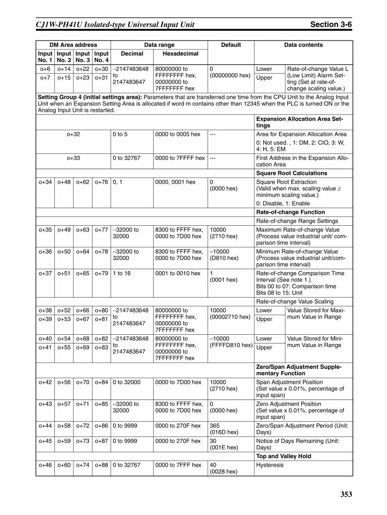
CJ1W-PH41U Isolated-type Universal Input Unit Section 3-6
o+6 o+14 o+22 o+30 −2147483648 to 2147483647
80000000 to FFFFFFFF hex, 00000000 to 7FFFFFFF hex
0 (00000000 hex)
Lower Rate-of-change Value L (Low Limit) Alarm Set-ting (Set at rate-of-change scaling value.)
o+7 o+15 o+23 o+31 Upper
Setting Group 4 (initial settings area): Parameters that are transferred one time from the CPU Unit to the Analog Input Unit when an Expansion Setting Area is allocated if word m contains other than 12345 when the PLC is turned ON or the Analog Input Unit is restarted.
Expansion Allocation Area Set-tings
o+32 0 to 5 0000 to 0005 hex --- Area for Expansion Allocation Area
0: Not used. , 1: DM, 2: CIO, 3: W, 4: H, 5: EM
o+33 0 to 32767 0000 to 7FFFF hex --- First Address in the Expansion Allo-cation Area
Square Root Calculations
o+34 o+48 o+62 o+76 0, 1 0000, 0001 hex 0 (0000 hex)
Square Root Extraction(Valid when max. scaling value ≥ minimum scaling value.) 0: Disable, 1: Enable
Rate-of-change Function
Rate-of-change Range Settings
o+35 o+49 o+63 o+77 −32000 to 32000
8300 to FFFF hex, 0000 to 7D00 hex
10000 (2710 hex)
Maximum Rate-of-change Value (Process value industrial unit/ com-parison time interval)
o+36 o+50 o+64 o+78 −32000 to 32000
8300 to FFFF hex, 0000 to 7D00 hex
−10000 (D810 hex)
Minimum Rate-of-change Value (Process value industrial unit/com-parison time interval)
o+37 o+51 o+65 o+79 1 to 16 0001 to 0010 hex 1 (0001 hex)
Rate-of-change Comparison Time Interval (See note 1.) Bits 00 to 07: Comparison timeBits 08 to 15: Unit
Rate-of-change Value Scaling
o+38 o+52 o+66 o+80 −2147483648 to 2147483647
80000000 to FFFFFFFF hex, 00000000 to 7FFFFFFF hex
10000 (00002710 hex)
Lower Value Stored for Maxi-mum Value in Rangeo+39 o+53 o+67 o+81 Upper
o+40 o+54 o+68 o+82 −2147483648 to 2147483647
80000000 to FFFFFFFF hex, 00000000 to 7FFFFFFF hex
−10000(FFFFD810 hex)
Lower Value Stored for Mini-mum Value in Rangeo+41 o+55 o+69 o+83 Upper
Zero/Span Adjustment Supple-mentary Function
o+42 o+56 o+70 o+84 0 to 32000 0000 to 7D00 hex 10000 (2710 hex)
Span Adjustment Position(Set value x 0.01%, percentage of input span)
o+43 o+57 o+71 o+85 −32000 to 32000
8300 to FFFF hex, 0000 to 7D00 hex
0 (0000 hex)
Zero Adjustment Position(Set value x 0.01%, percentage of input span)
o+44 o+58 o+72 o+86 0 to 9999 0000 to 270F hex 365 (016D hex)
Zero/Span Adjustment Period (Unit: Days)
o+45 o+59 o+73 o+87 0 to 9999 0000 to 270F hex 30 (001E hex)
Notice of Days Remaining (Unit: Days)
Top and Valley Hold
o+46 o+60 o+74 o+88 0 to 32767 0000 to 7FFF hex 40 (0028 hex)
Hysteresis
DM Area address Data range Default Data contents
Input No. 1
Input No. 2
Input No. 3
Input No. 4
Decimal Hexadecimal
353

CJ1W-PH41U Isolated-type Universal Input Unit Section 3-6
Note The settings for the Rate-of-change Comparison Time Interval, Integral ValueCalculation, Temperature Resistance Thermometer Compensation, and ColdJunction Compensation Method are as follows:
Integral Value Calculation (See note 1.)
o+47 o+61 o+75 o+89 (See note.) (See note.) 0 (0000 hex) Bits 00 to 07: Integer UnitBits 08 to 15: Integer Coefficient
Temperature Resistance Ther-mometer Compensation
o+90 (See note.) (See note.) 0 (0000 hex) Temperature Resistance Thermom-eter Compensation Enable (See note 1.)
o+91 o+93 o+95 o+97 −2147483648 to 2147483647
80000000 to FFFFFFFF hex, 00000000 to 7FFFFFFF hex
1089585403 (40F1C0FB hex)
Lower Reference Resistance (resistance at 23°C)(Set value × 0.0000001(10−7) Ω for Pt100 or JPt100,or Set value × 0.000001(10−6) Ω for Pt1000)
o+92 o+94 o+96 o+98 Upper
Cold Junction Compensation Method Settings
o+99 (See note.) (See note.) 0 (0000 hex) Cold Junction Compensation Method (See note 1.)
Address Bits Description Settings
o+37o+51o+65o+79
00 to 07 Rate-of-change Comparison Time Inter-val
Decimal Hexadecimal
1 to 16 0001 to 0010 hex
08 to 15 Unit 0: s1: Conversion period
o+47o+61o+75o+89
00 to 07 Integral Unit 0: Minutes1: Hours
08 to 15 Integer Coefficient 0: 11: 1/102: 1/1003: 1/1,0004: 1/10,000
o+90 00 Input No. 1 Temperature Resistance Thermometer Compensation
0: Disabled1: Enabled
01 Input No. 2 Temperature Resistance Thermometer Compensation
02 Input No. 3 Temperature Resistance Thermometer Compensation
03 Input No. 4 Temperature Resistance Thermometer Compensation
04 to 15 Not used.
o+99 00 Input No. 1 Cold Junction Compensation Method
0: Internal (Use the Unit's cold junction sensor.)1: External (Do not use the Unit's cold junction sensor.)01 Input No. 2 Cold Junction Compensation
Method
02 Input No. 3 Cold Junction Compensation Method
03 Input No. 4 Cold Junction Compensation Method
04 to 15 Not used.
DM Area address Data range Default Data contents
Input No. 1
Input No. 2
Input No. 3
Input No. 4
Decimal Hexadecimal
354
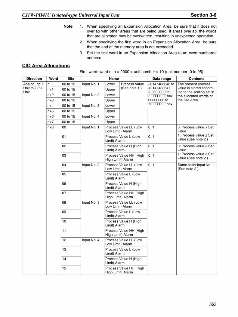
CJ1W-PH41U Isolated-type Universal Input Unit Section 3-6
Note 1. When specifying an Expansion Allocation Area, be sure that it does notoverlap with other areas that are being used. If areas overlap, the wordsthat are allocated may be overwritten, resulting in unexpected operation.
2. When specifying the first word in an Expansion Allocation Area, be surethat the end of the memory area is not exceeded.
3. Set the first word in an Expansion Allocation Area to an even-numberedaddress.
CIO Area AllocationsFirst word: word n. n = 2000 + unit number × 10 (unit number: 0 to 95)
Direction Word Bits Name Data range Contents
Analog Input Unit to CPU Unit
n 00 to 15 Input No. 1 Lower Process Value (See note 1.)
−2147483648 to +2147483647(80000000 to FFFFFFFF hex, 00000000 to 7FFFFFFF hex)
The present process value is stored accord-ing to the scaling set in the allocated words of the DM Area.
n+1 00 to 15 Upper
n+2 00 to 15 Input No. 2 Lower
n+3 00 to 15 Upper
n+4 00 to 15 Input No. 3 Lower
n+5 00 to 15 Upper
n+6 00 to 15 Input No. 4 Lower
n+7 00 to 15 Upper
n+8 00 Input No. 1 Process Value LL (Low Low Limit) Alarm
0, 1 0: Process value > Set value 1: Process value ≤ Set value (See note 2.)
01 Process Value L (Low Limit) Alarm
0, 1
02 Process Value H (High Limit) Alarm
0, 1 0: Process value < Set value 1: Process value ≥ Set value (See note 2.)
03 Process Value HH (High High Limit) Alarm
0, 1
04 Input No. 2 Process Value LL (Low Low Limit) Alarm
0, 1 Same as for input No. 1. (See note 2.)
05 Process Value L (Low Limit) Alarm
06 Process Value H (High Limit) Alarm
07 Process Value HH (High High Limit) Alarm
08 Input No. 3 Process Value LL (Low Low Limit) Alarm
09 Process Value L (Low Limit) Alarm
10 Process Value H (High Limit) Alarm
11 Process Value HH (High High Limit) Alarm
12 Input No. 4 Process Value LL (Low Low Limit) Alarm
13 Process Value L (Low Limit) Alarm
14 Process Value H (High Limit) Alarm
15 Process Value HH (High High Limit) Alarm
355

CJ1W-PH41U Isolated-type Universal Input Unit Section 3-6
Note 1. To indicate the process value in one word of data, set scaling in the rangeof −32,768 to 32,767 (8000 to FFFF hex or 0000 to 7FFF hex), and set theprocess value data length to 1 (one word).
2. If an Expansion Allocation Area is not set, the Process Value HH (HighHigh Limit) Alarm and Process Value LL (Low Low Limit) Alarm will be 0.
3. This value will be 0 if neither the Expansion Setting Area nor the ExpansionControl/Monitor Area is used.
4. This value will be 1 if an error occurs in the A/D conversion. If the error isnot cleared by turning the power OFF and back ON or restarting the Unit,check whether there is a source of noise nearby. For details, refer to ErrorProcessing on page 363.
Analog Input Unit to CPU Unit
n+9 00 Input No. 1 Rate-of-change Value L (Low Limit) Alarm
0, 1 0: Rate of change > Set value 1: Rate of change ≤ Set value (See note 3.)
01 Rate-of-change Value H (High Limit) Alarm
0, 1 0: Rate of change < Set value 1: Rate of change ≥ Set value (See note 3.)
02 Input No. 2 Rate-of-change Value L (Low Limit) Alarm
0, 1 Same as for input No. 1. (See note 3.)
03 Rate-of-change Value H (High Limit) Alarm
0, 1
04 Input No. 3 Rate-of-change Value L (Low Limit) Alarm
0, 1
05 Rate-of-change Value H (High Limit) Alarm
0, 1
06 Input No. 4 Rate-of-change Value L (Low Limit) Alarm
0, 1
07 Rate-of-change Value H (High Limit) Alarm
0, 1
08 Input No. 1 Input Error 0, 1 0: Normal1: Error09 Input No. 2
10 Input No. 3
11 Input No. 4
12 Cold Junction Sensor Error 0, 1 0: Normal1: Error
13 Zero/Span Adjustment Period End 0, 1 0: Adjustment enabled.1: Adjustment ended. (See note 3.)Remains set to 1 if the zero/span adjustment bit has never been ON.
14 Zero/span Adjustment Period Notice 0, 1 0: Adjustment enabled.1: Notice period in effect. (See note 3.)Remains set to 1 if the zero/span adjustment bit has never been ON.
15 A/D Conversion Error (See note 4.) 0, 1 0: Normal1: Error
Direction Word Bits Name Data range Contents
356
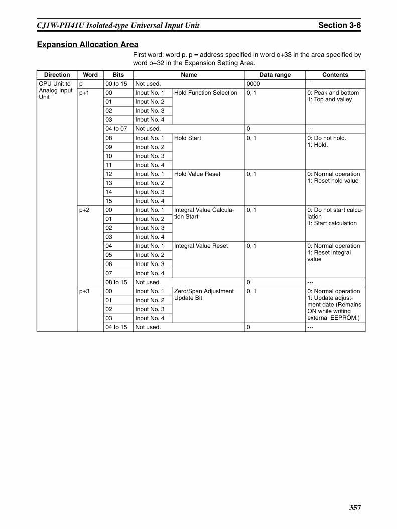
CJ1W-PH41U Isolated-type Universal Input Unit Section 3-6
Expansion Allocation AreaFirst word: word p. p = address specified in word o+33 in the area specified byword o+32 in the Expansion Setting Area.
Direction Word Bits Name Data range Contents
CPU Unit to Analog Input Unit
p 00 to 15 Not used. 0000 ---
p+1 00 Input No. 1 Hold Function Selection 0, 1 0: Peak and bottom1: Top and valley01 Input No. 2
02 Input No. 3
03 Input No. 4
04 to 07 Not used. 0 ---
08 Input No. 1 Hold Start 0, 1 0: Do not hold.1: Hold.09 Input No. 2
10 Input No. 3
11 Input No. 4
12 Input No. 1 Hold Value Reset 0, 1 0: Normal operation1: Reset hold value13 Input No. 2
14 Input No. 3
15 Input No. 4
p+2 00 Input No. 1 Integral Value Calcula-tion Start
0, 1 0: Do not start calcu-lation1: Start calculation
01 Input No. 2
02 Input No. 3
03 Input No. 4
04 Input No. 1 Integral Value Reset 0, 1 0: Normal operation1: Reset integral value
05 Input No. 2
06 Input No. 3
07 Input No. 4
08 to 15 Not used. 0 ---
p+3 00 Input No. 1 Zero/Span Adjustment Update Bit
0, 1 0: Normal operation1: Update adjust-ment date (Remains ON while writing external EEPROM.)
01 Input No. 2
02 Input No. 3
03 Input No. 4
04 to 15 Not used. 0 ---
357

CJ1W-PH41U Isolated-type Universal Input Unit Section 3-6
Analog Input Unit to CPU Unit
p+4 00 to 15 Input No. 1 Lower Rate of Change (See note.)
−2147483648 to 2147483647(80000000 to FFFFFFFF hex, 00000000 to 7FFFFFFF hex)
The present rate-of-change value is stored according to the scaling set in the Expansion Setting Area.
p+5 00 to 15 Upper
p+6 00 to 15 Input No. 2 Lower
p+7 00 to 15 Upper
p+8 00 to 15 Input No. 3 Lower
p+9 00 to 15 Upper
p+10 00 to 15 Input No. 4 Lower
p+11 00 to 15 Upper
p+12 00 Input No. 1 Zero/Span Adjustment Period End
0, 1 0: Adjustment enabled.1: Adjustment ended. Remains set to 1 if the Zero/Span Adjustment Bit has never been ON.
01 Zero/Span Adjustment Period Notice
0, 1 0: Adjustment enabled.1: Notice period in effect.Remains set to 1 if the Zero/Span Adjustment Bit has never been ON.
02 Input No. 2 Zero/Span Adjustment Period End
0, 1 Same as input No. 1.
03 Zero/Span Adjustment Period Notice
0, 1
04 Input No. 3 Zero/Span Adjustment Period End
0, 1
05 Zero/Span Adjustment Period Notice
0, 1
06 Input No. 4 Zero/Span Adjustment Period End
0, 1
07 Zero/Span Adjustment Period Notice
0, 1
08 EEPROM Error 0, 1 0: Normal1: Error
09 to 15 Not used. 0 ---
p+13 00 to 15 Input No. 1 Day of Final Adjustment Date
0100 to 3100(BCD) Records the last date when the Zero/Span Adjustment Update Bit was turned ON. Remains set to FFFF if the Zero/Span Adjust-ment Update Bit has never been ON.
p+14 00 to 15 Year and Month of Final Adjustment Date
0001 to 9912(BCD)
p+15 00 to 15 Input No. 2 Day of Final Adjustment Date
0100 to 3100(BCD)
p+16 00 to 15 Year and Month of Final Adjustment Date
0001 to 9912(BCD)
p+17 00 to 15 Input No. 3 Day of Final Adjustment Date
0100 to 3100(BCD)
p+18 00 to 15 Year and Month of Final Adjustment Date
0001 to 9912(BCD)
p+19 00 to 15 Input No. 4 Day of Final Adjustment Date
0100 to 3100(BCD)
p+20 00 to 15 Year and Month of Final Adjustment Date
0001 to 9912(BCD)
Direction Word Bits Name Data range Contents
358

CJ1W-PH41U Isolated-type Universal Input Unit Section 3-6
Analog Input Unit to CPU Unit
p+21 00 Input No. 1 Valley Detection Timing Flag
0, 1 Turns ON when a valley is detected for the valley hold func-tion. Turns OFF the next cycle.
01 Top Detection Timing Flag
0, 1 Turns ON when a top is detected for the top hold function. Turns OFF the next cycle.
02 Input No. 2 Valley Detection Timing Flag
0, 1 Same as input No. 1.
03 Top Detection Timing Flag
0, 1
04 Input No. 3 Valley Detection Timing Flag
0, 1
05 Top Detection Timing Flag
0, 1
06 Input No. 4 Valley Detection Timing Flag
0, 1
07 Top Detection Timing Flag
0, 1
08 to 15 Not used. 0 ---
p+22 00 to 15 Input No. 1 Lower Peak/Top Value (See note.)
−2147483648 to 2147483647(80000000 to FFFFFFFF hex, 00000000 to 7FFFFFFF hex)
The peak or top value is stored according to the scaling set in the DM Area.
p+23 00 to 15 Upper
p+24 00 to 15 Lower Bottom/Valley Value (See note.)
−2147483648 to 2147483647(80000000 to FFFFFFFF hex, 00000000 to 7FFFFFFF hex)
The bottom or valley value is stored according to the scaling set in the DM Area.
p+25 00 to 15 Upper
p+26 00 to 15 Input No. 2 Lower Peak/Top Value (See note.)
−2147483648 to 2147483647(80000000 to FFFFFFFF hex, 00000000 to 7FFFFFFF hex)
Same as for input No. 1.p+27 00 to 15 Upper
p+28 00 to 15 Lower Bottom/Valley Value (See note.)
p+29 00 to 15 Upper
p+30 00 to 15 Input No. 3 Lower Peak/Top Value (See note.)p+31 00 to 15 Upper
p+32 00 to 15 Lower Bottom/Valley Value (See note.)
p+33 00 to 15 Upper
p+34 00 to 15 Input No. 4 Lower Peak/Top Value (See note.)p+35 00 to 15 Upper
p+36 00 to 15 Lower Bottom/Valley Value (See note.)
p+37 00 to 15 Upper
Direction Word Bits Name Data range Contents
359
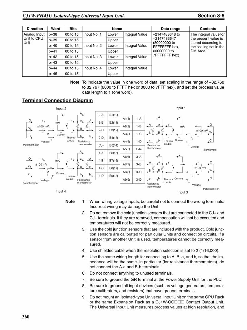
CJ1W-PH41U Isolated-type Universal Input Unit Section 3-6
Note To indicate the value in one word of data, set scaling in the range of −32,768to 32,767 (8000 to FFFF hex or 0000 to 7FFF hex), and set the process valuedata length to 1 (one word).
Terminal Connection Diagram
Note 1. When wiring voltage inputs, be careful not to connect the wrong terminals.Incorrect wiring may damage the Unit.
2. Do not remove the cold junction sensors that are connected to the CJ+ andCJ− terminals. If they are removed, compensation will not be executed andtemperatures will not be correctly measured.
3. Use the cold junction sensors that are included with the product. Cold junc-tion sensors are calibrated for particular Units and connection circuits. If asensor from another Unit is used, temperatures cannot be correctly mea-sured.
4. Use shielded cable when the resolution selection is set to 2 (1/16,000).
5. Use the same wiring length for connecting to A, B, a, and b, so that the im-pedance will be the same. In particular (for resistance thermometers), donot connect the A-a and B-b terminals.
6. Do not connect anything to unused terminals.
7. Be sure to ground the GR terminal at the Power Supply Unit for the PLC.
8. Be sure to ground all input devices (such as voltage generators, tempera-ture calibrators, and resistors) that have ground terminals.
9. Do not mount an Isolated-type Universal Input Unit on the same CPU Rackor the same Expansion Rack as a CJ1W-OC@@@ Contact Output Unit.The Universal Input Unit measures process values at high resolution, and
Analog Input Unit to CPU Unit
p+38 00 to 15 Input No. 1 Lower Integral Value −2147483648 to +2147483647(80000000 to FFFFFFFF hex, 00000000 to 7FFFFFFF hex)
The integral value for the present value is stored according to the scaling set in the DM Area.
p+39 00 to 15 Upper
p+40 00 to 15 Input No. 2 Lower Integral Value
p+41 00 to 15 Upper
p+42 00 to 15 Input No. 3 Lower Integral Value
p+43 00 to 15 Upper
p+44 00 to 15 Input No. 4 Lower Integral Value
p+45 00 to 15 Upper
Direction Word Bits Name Data range Contents
2-A B1(10)
A1(1) 1- A 2-B B2(11)
A2(2) 1- B 2-C B3(12)
A3(3) 1- C 2-D B4(13)
A4(4) 1- D CJ− B5(14)
A5(5) CJ+ 4-A B6(15)
A6(6) 3-A 4-B B7(16)
A7(7) 3-B 4-C B8(17)
A8(8) 3-C 4-D B9(18)
A9(9) 3-D
B
A
b
B
a
b
A
+
−
+
− −
+
W
O
C
B
A
b
B
a
b
A
+
−
+
− −
+
W
O
C
mA
V
mA
V
+
−
+
−
B
A
b
B
a
b
A
+
−
+
− −
+
W
O
C
mA
V
+
− B
A
b
B
a
b
A
+
−
+
− −
+
W
O
C
mA
V
+
−
±100 mV
Input 2
PotentiometerVoltage
Current
±100 mV
±100 mV
Input 1
±100 mV
Input 4 Input 3
Thermo-couple Resistance
thermometer
PotentiometerVoltage
CurrentThermo-couple Resistance
thermometer
PotentiometerVoltage
CurrentThermo-coupleResistance
thermometer
Potentiometer
Voltage
CurrentThermo-coupleResistance
thermometer
360
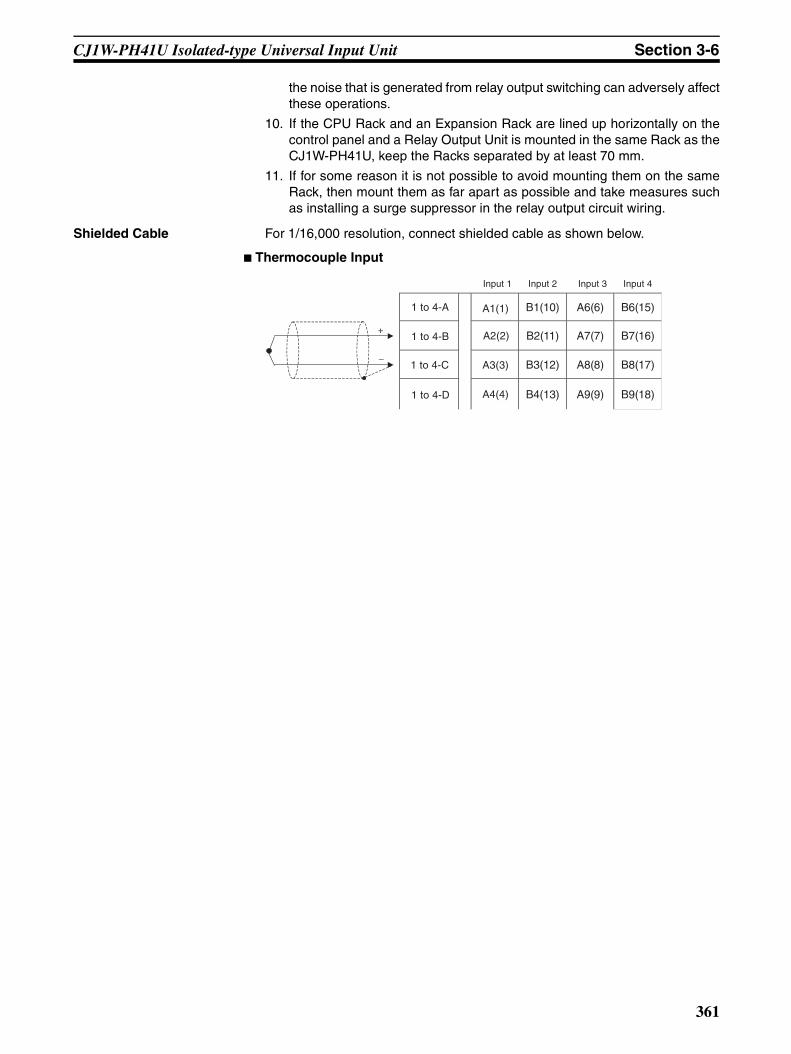
CJ1W-PH41U Isolated-type Universal Input Unit Section 3-6
the noise that is generated from relay output switching can adversely affectthese operations.
10. If the CPU Rack and an Expansion Rack are lined up horizontally on thecontrol panel and a Relay Output Unit is mounted in the same Rack as theCJ1W-PH41U, keep the Racks separated by at least 70 mm.
11. If for some reason it is not possible to avoid mounting them on the sameRack, then mount them as far apart as possible and take measures suchas installing a surge suppressor in the relay output circuit wiring.
Shielded Cable For 1/16,000 resolution, connect shielded cable as shown below.
Thermocouple Input
B1(10) A6(6) B6(15)
B2(11) A7(7) B7(16)
B3(12) A8(8) B8(17)
B4(13) A9(9) B9(18)
Input 1
+
−
Input 2 Input 3 Input 4
1 to 4-A
1 to 4-B
1 to 4-C
1 to 4-D
A1(1)
A2(2)
A3(3)
A4(4)
361

CJ1W-PH41U Isolated-type Universal Input Unit Section 3-6
Block Diagram
CH
1 in
put
CH
2 in
put
Col
d ju
nctio
n
sens
orC
H3
inpu
t C
H4
inpu
t
Con
nect
or
Isolated circuit
Input circuit A/D converter
5 VDCPower supply circuit
Isolated circuit
Isolated circuit
Isolated circuit
Input circuit A/D converter
Input circuit A/D converter
Input circuit A/D converter
Input circuit A/D converter
Digital isolator
Digital isolator
Digital isolator
Digital isolator
362
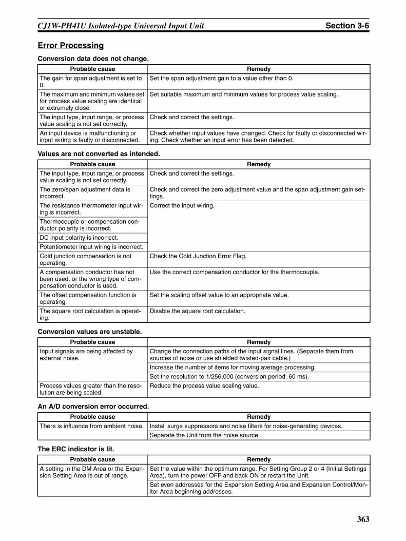
CJ1W-PH41U Isolated-type Universal Input Unit Section 3-6
Error Processing
Conversion data does not change.
Values are not converted as intended.
Conversion values are unstable.
An A/D conversion error occurred.
The ERC indicator is lit.
Probable cause Remedy
The gain for span adjustment is set to 0.
Set the span adjustment gain to a value other than 0.
The maximum and minimum values set for process value scaling are identical or extremely close.
Set suitable maximum and minimum values for process value scaling.
The input type, input range, or process value scaling is not set correctly.
Check and correct the settings.
An input device is malfunctioning or input wiring is faulty or disconnected.
Check whether input values have changed. Check for faulty or disconnected wir-ing. Check whether an input error has been detected.
Probable cause Remedy
The input type, input range, or process value scaling is not set correctly.
Check and correct the settings.
The zero/span adjustment data is incorrect.
Check and correct the zero adjustment value and the span adjustment gain set-tings.
The resistance thermometer input wir-ing is incorrect.
Correct the input wiring.
Thermocouple or compensation con-ductor polarity is incorrect.
DC input polarity is incorrect.
Potentiometer input wiring is incorrect.
Cold junction compensation is not operating.
Check the Cold Junction Error Flag.
A compensation conductor has not been used, or the wrong type of com-pensation conductor is used.
Use the correct compensation conductor for the thermocouple.
The offset compensation function is operating.
Set the scaling offset value to an appropriate value.
The square root calculation is operat-ing.
Disable the square root calculation.
Probable cause Remedy
Input signals are being affected by external noise.
Change the connection paths of the input signal lines. (Separate them from sources of noise or use shielded twisted-pair cable.)
Increase the number of items for moving average processing.
Set the resolution to 1/256,000 (conversion period: 60 ms).
Process values greater than the reso-lution are being scaled.
Reduce the process value scaling value.
Probable cause Remedy
There is influence from ambient noise. Install surge suppressors and noise filters for noise-generating devices.
Separate the Unit from the noise source.
Probable cause Remedy
A setting in the DM Area or the Expan-sion Setting Area is out of range.
Set the value within the optimum range. For Setting Group 2 or 4 (Initial Settings Area), turn the power OFF and back ON or restart the Unit.
Set even addresses for the Expansion Setting Area and Expansion Control/Mon-itor Area beginning addresses.
363

CJ1W-PH41U Isolated-type Universal Input Unit Section 3-6
364

Appendix ASupplementary Explanation of Functions
The following supplements the explanation given in 1-2 Features and Functions.
Changing Set Values during Output of Process Value (or Instantaneous Value) Alarm or Rate-of-change AlarmHH (High High Limit) and H (High Limit) AlarmsWhen the alarm set value is raised while the alarm output is ON, the alarm output will be turned OFF when thefollowing condition is satisfied.Input value < (alarm set value after change – hysteresis)The alarm output will first turn OFF when the input value falls below the set value (with the hysteresis included).
LL (Low Low Limit) and L (Low Limit) AlarmsWhen the alarm set value is lowered while the alarm output is ON, the alarm output will be turned OFF whenthe following condition is satisfied.Input value > (alarm set value after change + hysteresis)When the hysteresis part alone of the input value is greater than the set value, the alarm output will turn OFFfor the first time.
Example: HH and H Limit Alarms
Alarm set value raised.
Alarm set value further raised.
Hysteresis
H, HH alarm set value
With present value at this point, alarm output turns ON.
Input value (Process value, rate-of-change value, instantaneous value)
Hysteresis
Input value (Process value, rate-of-change value, instantaneous value)
With present value at this point, alarm output remains ON.
H, HH alarm set value
Hysteresis
Input value (Process value, rate-of-change value, instantaneous value)
With present value at this point, alarm output turns OFF.
H, HH alarm set value
365

Supplementary Explanation of Functions Appendix A
Alarm Operation when Upper Limit Is Less Than Lower LimitProcess value (instantaneous value) and rate-of-change value alarm set values can be set freely regardless ofthe relative sizes of HH > H > L > LL.
Example: H < L, or HH < H.
The alarm output operation is determined purely by the relative sizes of the input value (screening value) andalarm set value, as shown below.
HH and H Limit AlarmsWhen the input value is greater than the alarm set value, the alarm output is turned ON.
LL and L Limit AlarmsWhen the input value is less than the alarm set value, the alarm output is turned ON.
Note Rate-of-change value alarm is not available for CS1W-PTS5@/PDC55, and CJ1W-PTS51/PTS52. Pro-cess value alarm only.
Applicable Units Isolated-type Thermocouple Input Units CS1W-PTS01-V1/11/51/55, CJ1W-PTS51/15
Isolated-type Resistance Thermometer Input Units
CS1W-PTS02/03/12/52/56, CJ1W-PTS52/16
Isolated-type 2-Wire Transmitter Input Unit CS1W-PTW01
Isolated-type Direct Current Input Units CS1W-PDC01/11/55, CJ1W-PDC15
Isolated-type Pulse Input Unit CS1W-PPS01
Power Transducer Input Unit CS1W-PTR01
Analog Input Unit (100 mV) CS1W-PTR02
Isolated-type Universal Input Units CS1W-PH41U
Process value or rate-of-change value
Hysteresis
Low limit (L) set value
High limit (H) set value
Low limit (L) alarm output
High limit (H) alarm output
Time
Time
Time
Applicable Units Isolated-type Thermocouple Input Units CS1W-PTS01-V1/11/51/55, CJ1W-PTS51/15
Isolated-type Resistance Thermometer Input Units
CS1W-PTS02/03/12/52/56, CJ1W-PTS52/16
Isolated-type 2-Wire Transmitter Input Unit CS1W-PTW01
Isolated-type Direct Current Input Units CS1W-PDC01/11/55, CJ1W-PDC15
Isolated-type Pulse Input Unit CS1W-PPS01
Power Transducer Input Unit CS1W-PTR01
Analog Input Unit (100 mV) CS1W-PTR02
Isolated-type Universal Input Units CJ1W-PH41U
366

Supplementary Explanation of Functions Appendix A
Alarm Output Operation when Falling Back from Alarm Condition Before Alarm-ON Delay Time ElapsesIf inputs fall back from the alarm-ON condition (including hysteresis) before the alarm-ON delay time haselapsed, the alarm output will not turn ON.
Note The alarm will not be turned OFF even if the alarm OFF condition is no longer met before the alarmOFF-delay time expires.
Setting Process Value Scaling with Negative BiasWith process value scaling in industrial units, a negative bias can be set by reversing the maximum and mini-mum values in the range.
Example: CS1W-PDC01 Isolated-type Direct Current Input Unit
The following values can be set for an input signal of 4 to 20 mA: Maximum process value in range = 0, mini-mum process value in range = 4000.
Process value or rate-of-change valueFalling back from ON condition
Set value Hysteresis
Time
Alarm output Will not turn ON
Time
Alarm-ON delay time
Applicable Units Isolated-type Thermocouple Input Units CS1WPTS01-V1/11/51/55, CJ1W-PTS51/15
Isolated-type Resistance Thermometer Input Units
CS1W-PTS02/03/12/52/56, CJ1W-PTS52/16
Isolated-type 2-Wire Transmitter Input Unit CS1W-PTW01
Isolated-type Direct Current Input Units CS1W-PDC01/11/55, CJ1W-PDC15
Isolated-type Pulse Input Unit CS1W-PPS01
Power Transducer Input Unit CS1W-PTR01
Analog Input Unit (100 mV) CS1W-PTR02
Isolated-type Universal Input Units CJ1W-PH41U (See note.)
367
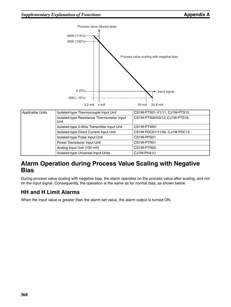
Supplementary Explanation of Functions Appendix A
Alarm Operation during Process Value Scaling with Negative BiasDuring process value scaling with negative bias, the alarm operates on the process value after scaling, and noton the input signal. Consequently, the operation is the same as for normal bias, as shown below.
HH and H Limit AlarmsWhen the input value is greater than the alarm set value, the alarm output is turned ON.
Process value (stored data)
Input signal
3.2 mA 4 mA 20 mA 20.8 mA
−600 (−15%)
0 (0%)
4000 (100%)
4600 (115%)
Process value scaling with negative bias
Applicable Units Isolated-type Thermocouple Input Unit CS1W-PTS01-V1/11, CJ1W-PTS15
Isolated-type Resistance Thermometer Input Unit
CS1W-PTS02/03/12, CJ1W-PTS16
Isolated-type 2-Wire Transmitter Input Unit CS1W-PTW01
Isolated-type Direct Current Input Unit CS1W-PDC01/11/55, CJ1W-PDC15
Isolated-type Pulse Input Unit CS1W-PPS01
Power Transducer Input Unit CS1W-PTR01
Analog Input Unit (100 mV) CS1W-PTR02
Isolated-type Universal Input Units CJ1W-PH41U
368
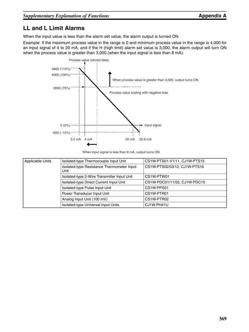
Supplementary Explanation of Functions Appendix A
LL and L Limit AlarmsWhen the input value is less than the alarm set value, the alarm output is turned ON.
Example: If the maximum process value in the range is 0 and minimum process value in the range is 4,000 foran input signal of 4 to 20 mA, and if the H (high limit) alarm set value is 3,000, the alarm output will turn ONwhen the process value is greater than 3,000 (when the input signal is less than 8 mA).
Applicable Units Isolated-type Thermocouple Input Unit CS1W-PTS01-V1/11, CJ1W-PTS15
Isolated-type Resistance Thermometer Input Unit
CS1W-PTS02/03/12, CJ1W-PTS16
Isolated-type 2-Wire Transmitter Input Unit CS1W-PTW01
Isolated-type Direct Current Input Unit CS1W-PDC01/11/55, CJ1W-PDC15
Isolated-type Pulse Input Unit CS1W-PPS01
Power Transducer Input Unit CS1W-PTR01
Analog Input Unit (100 mV) CS1W-PTR02
Isolated-type Universal Input Units CJ1W-PH41U
Process value (stored data)
When process value is greater than 3,000, output turns ON.
Process value scaling with negative bias
Input signal
When input signal is less than 8 mA, output turns ON.
3.2 mA 4 mA 20 mA 20.8 mA
−600 (−15%)
0 (0%)
4000 (100%)
4600 (115%)
3000 (75%)
369

Supplementary Explanation of Functions Appendix A
Maximum/Minimum Value for when Input Disconnection Occurs during Process Value Scaling with Negative BiasIf an input is disconnected during process value scaling with negative bias, either the maximum or minimumprocess value will be specified.
If the process value overrange direction is high, the maximum process value will be specified.
If the process value overrange direction is low, the minimum process value will be specified.
Applicable Units Isolated-type Thermocouple Input Unit CS1W-PTS01-V1/11, CJ1W-PTS15
Isolated-type Resistance Thermometer Input Unit
CS1W-PTS02/03/12, CJ1W-PTS16
Isolated-type Universal Input Units CJ1W-PH41U
Process value (stored data)
If the high value is set, the maximum value of 4600 will be specified when an input is disconnected.
Process value scaling with negative bias
Input signalIf the low value is set, the minimum value of −600 will be specified when an input is disconnected.
3.2 mA 4 mA 20 mA 20.8 mA
−600 (−15%)
0 (0%)
4000 (100%)
4600 (115%)
370

Supplementary Explanation of Functions Appendix A
Output Hold when CPU Unit Error OccursIn the following cases, the CS1W-PMV01/PMV02 Isolated-type Analog Output Unit will hold either a specifiedpreset value or the analog output value prior to the error for output when the CPU Unit is restored to normaloperation.
• A fatal error (including user-defined FALS execution) occurs
• A CPU error occurs
• A load break occurs
When the CPU Unit is restored to normal operation, the output value in the CIO Area will be output.
Note If a CPU error occurs while the output rate-of-change limit function is operating, the output hold functionwill operate as follows:
• If previous value hold has been specified, then the value prior to the CPU error will be held for output.
• When preset value hold has been specified, the output rate-of-change limit will remain in effect even duringthe change to the preset value, and the rate of change will be limited.
Inrush Input Limit FunctionThe inrush input limit function will not operate if the process value is already greater than 2% when the powersupply to the PLC is turned ON. The inrush input limit function will operate only when the process value risesabove 2% from less than 2% at startup.
No output rate-of-change limit
No CPU error occurs.
Previous value held when CPU error occurs
Rate-of-change limit in effect
CPU error occurs here.
Time
Analog output value
Applicable Units Isolated-type Analog Output Units CS1W-PMV01/PMV02
Analog output value
No CPU error occurs.
Rate-of-change limit enabled
Preset valueNo rate-of-change limit
CPU error occurs.
Rate-of-change limit still enabled.
Time
Previous value held when CPU error occurs
Process value
Operation of inrush input limit function
Time
371

Supplementary Explanation of Functions Appendix A
Hysteresis during Square Root CalculationsDuring square root calculations, outputs of approximately 7% or less have linear characteristics (i.e., output =input). Hysteresis exists, however, when switching between square root characteristics and linear characteris-tics, as shown below.
During input rise: Switching from linear characteristics to square root characteristics at 0.5% input (output ofapproximately 7%).
During input fall: Switching from square root characteristics to linear characteristics at 0.3% input (output ofapproximately 5.5%).
Adjustment Period Control
Final Adjustment Date Not Stored in the Unit’s External FROM (Initial Status) The set values are as follows:
• The 4-byte area (2 words) for the final adjustment date is set to FFFF.
• The Zero/span Adjustment Period Notice Bit is set to 1 (notice period).
• The Zero/span Adjustment Period End Bit is set to 1 (adjustment ended).
Error in Final Adjustment Date Stored in Unit’s External FROM when Power is Turned ONThe ERC indicator is ON and the adjustment period control function does not operate properly.Restart the Unit. The set values are as follows.
• The External FROM Error Flag is set to 1 (external FROM error).
• The 4-byte area (2 words) for the final adjustment date is set to FFFF.
• The Zero/span Adjustment Period Notice Bit is set to 1 (notice period).
• The Zero/span Adjustment Period End Bit is set to 1 (adjustment ended).
Applicable Units Analog Input Unit (100 mV) CS1W-PTR02
Power Transducer Input Unit CS1W-PTR01
Output
Square root calculation
InputLinear
0.5%
0.3%
2%
5.5%
7%
Applicable Units Isolated-type 2-Wire Transmitter Input Unit CS1W-PTW01
Isolated-type Direct Current Input Unit CS1W-PDC01/11/55, CJ1W-PDC15
Isolated-type Universal Input Units CS1W-PH41U
372

Supplementary Explanation of Functions Appendix A
Error in Unit’s External FROM when Updating Final Adjustment DateThe ERC indicator is ON and the adjustment period control function does not operate properly when the Unit isrestarted. Update the final adjustment date again. The set values are as follows.
• The External FROM Error Flag is set to 1 (external FROM error).
Note If the CPU Unit’s internal clock information is refreshed after updating the final adjustment date, thewarning will not be accurate. The Zero/span Adjustment Update Bit remains ON (1: Update adjustmentdate) while writing external FROM, so do not turn OFF the PLC.
Note For the CJ1W-PH41U, the “external FROM” is an external EEPROM.
Integral Value Calculation
Integral Value Unit: HourThe process value is calculated using an integral width of 3.6 s (1/1,000th of an hour), and the total is output to4 bytes (2 words) of memory.
An integral value of 1,000 indicates that a process value of 1,000 has continued for one hour.
Integral Value Unit: MinuteThe process value is calculated using an integral width of 60 ms (1/1,000th of a minute), and the total is outputto 4 bytes (2 words) of memory.
An integral value of 1,000 indicates that a process value of 1,000 has continued for one minute.
Example: Process value: 1,000 (constant)Integral unit: hour
Applicable Units Isolated-type Thermocouple Input Unit CS1W-PTS11, CJ1W-PTS15
Isolated-type Resistance Thermometer Input Unit
CS1W-PTS12, CJ1W-PTS16
Isolated-type Direct Current Input Unit CS1W-PDC11, CJ1W-PDC15
Isolated-type Universal Input Units CJ1W-PH41U (See note.)
Time lapsed (hours) Integral value
0.5 500
1 1,000
2 2,000
3 3,000
373

Supplementary Explanation of Functions Appendix A
Note The integral width for one integral value is as follows:
Integral Value OverflowThe integral value will become undefined if the integral value exceeds the data range (–2147483648 to2147483647) during integral calculation. For the CJ1W-PDC15, an integral value overflow will occur after aminimum of 45 days has lapsed from the start of integral calculation.Example: Integral value overflow (minimum conditions). The table shows the integral values for the followingminimum conditions.
• Process value: –32768 (constant)
• Integral unit: Minute
Note Use the Integral Value Calculation Start Bit, the Integral Value Reset Bits, and (for the CJ1W-PH41Uonly) the integral coefficient so that an integral value overflow does not occur.
ON
OFF
ON
OFF
Integral value
Time
Time
Time
Time
Integral value
Process value
Integral Value Reset Bit
Integral Value Calculation Start Bit
Integral width (See note.)
Unit Integral width
Hour 3.6 s (1/1,000th of an hour)
Minute 60 ms (1/1,000th of a minute)
Number of days lapsed (days)
Integral value
0 0
1 −47185920
2 −94371840
to to
45 −2123366400
46 Undefined
Applicable Units Isolated-type Direct Current Input Unit CS1W-PDC11, CJ1W-PDC15
Isolated-type Universal Input Units CJ1W-PH41U
374

Appendix BZero/Span Adjustment Example
The Analog I/O Unit’s zero/span adjustment can be performed as described below using a calibration device.
1,2,3... 1. Connect the Programming Device to the CPU Unit.
2. Connect a suitable calibration device as shown in the following table to the Analog I/O Unit.
3. Turn ON the power to the PLC, and wait approximately 10 minutes for the Unit to warm up.The CS1W-PTS5@ and CJ1W-PTS5@ require approximately 30 minutes to warm up.The CS1W-PTS01-V1, CS1W-PTS11, and CJ1W-PTS15/PH41U require approximately 45 min-utes to warm up.
4. Make the adjustments.
Name Model Calibration device
Isolated-type Thermocouple Input Unit CS1W-PTS01-V1 Voltage and current generator
CS1W-PTS11
CS1W-PTS51
CS1W-PTS55
CJ1W-PTS51
CJ1W-PTS15
Isolated-type Universal Input Unit (thermo-couple inputs)
CJ1W-PH41U
Isolated-type Resistance Thermocouple Input Unit (Pt100, JPt100)
CS1W-PTS02 Variable resistor
Isolated-type Resistance Thermocouple Input Unit (Ni508.4)
CS1W-PTS03
Isolated-type Resistance Thermocouple Input Unit (Pt100, JPt100, JPt50, Ni508.4)
CS1W-PTS12
CJ1W-PTS16
Isolated-type Resistance Thermocouple Input Unit (Pt100, JPt100)
CS1W-PTS52
CS1W-PTS56
Isolated-type Resistance Thermocouple Input Unit (Pt100, JPt100)
CJ1W-PTS52
Isolated-type Universal Input Unit (Pt100, JPt100, Pt1000)
CJ1W-PH41U
Isolated-type 2-Wire Transmitter Input Unit CS1W-PTW01 Voltage and current generator
Isolated-type Direct Current Input Unit CS1W-PDC01 Voltage and current generator
CS1W-PDC11
CS1W-PDC55
CJ1W-PDC15
Isolated-type Universal Input Units (direct current inputs)
CJ1W-PH41U
Analog Input Unit (100 mV) CS1W-PTR02 Voltage generator
Power Transducer Input Unit CS1W-PTR01 Voltage generator
Isolated-type Pulse Input Unit CS1W-PPS01 Pulse generator
Isolated-type Analog Output Unit CS1W-PMV01 Voltage and current meter
CS1W-PMV02 Voltage meter
375

Zero/Span Adjustment Example Appendix B
Input Units1,2,3... 1. Input a signal equivalent to 0% from the calibration device, and check the process value in the CPU
Unit’s CIO Area using the Programming Device. If the value is abnormal, change the zero adjust-ment value in the DM Area, and adjust the offset (parallel movement) value.
2. Input a signal equivalent to 100% from the calibration device, and check the process value in theCPU Unit’s CIO Area using the Programming Device. If the value is abnormal, change the spanadjustment gain value in the DM Area, and adjust the gain (bias).
Note For the CJ1W-PTS15 Isolated-type Thermocouple Input Unit or CJ1W-PH41U Universal Input Unit, con-nect the terminals of the cold junction sensor. For the CJ1W-PTS15 Isolated-type Thermocouple InputUnit, connect the terminals for the cold junction sensor on the top. This will make the Isolated-type Ther-mocouple Input Unit or Universal Input Unit discontinue cold junction compensation. Then input a stan-dard thermocouple value of 0°C (standard thermal power generation value, IEC 60584-1) to thecalibration mV signal.
Output Units1,2,3... 1. Set an analog output value equivalent to 0% in the CPU Unit’s CIO Area. Check the signal using
the calibration device. If the value is abnormal, change the zero adjustment value in the DM Area,and adjust the offset (parallel movement) value.
2. Set an analog output value equivalent to 100% in the CPU Unit’s CIO Area. Check the signal usingthe calibration device. If the value is abnormal, change the span adjustment gain value in the DMArea, and adjust the gain (bias).
Adjust the zero/span according to the following equation.
Process value after adjustment = (input value – minimum process value in range) x DM Area span adjustmentgain value + minimum process value in range + DM Area zero adjustment value
Example: Minimum process value in range = 0; maximum process value in range = 4,000; span adjustmentgain = 10060 x 0.0001 = 1.0060; zero adjustment value = 5
If the input value is 500, the process value after adjustment will be as follows:
Process value after adjustment = (500 – 0) x 1.0060 + 0 + 5 = 508.
Process value (after adjustment = stored data)Span adjustment gain (example: 1.006)
Zero adjustment value (example: 5)
Process value (before adjustment)
−600 (−15%)
4600 (115%)
4000 (100%)
508
50 (0%)
−600 0 500 4000 4600
376

Zero/Span Adjustment Example Appendix B
Zero/span Adjustment Example for Any Points (CS1W-PTS11/12, PDC11, CJ1W-PTS15/16, PDC15, PH41U)Use the following adjustment equation to perform zero/span adjustment for any points.
Process value after adjustment = (X − B) × ((C − A) × E − B + A)/(C − B) + D + B
X: Input valueA: Zero point of allocated DM Area
B: Zero adjustment position (process value range)
C: Span adjustment position (process value range)
D: Zero adjustment value for allocated DM Area
E: Span adjustment gain for allocated DM Area
Note The zero adjustment position and span adjustment position are percentages of the input span in theExpansion Setting Area settings, so they can be obtained using the following equations.
Zero adjustment position = (Span point set in the allocated DM Area – Zero point set in the allocated DMArea) × Zero adjustment position set in the Expansion Setting Area + Zero point set in the allocated DMArea
Span adjustment position = (Span point set in the allocated DM Area – Zero point set in the allocatedDM Area) × Span adjustment position set in the Expansion Setting Area + Zero point set in the allocatedDM Area
Example: The values are calculated for the conditions in the following table.
Note For the CJ1W-PH41U, the space adjustment gain setting is 10060000 (10060000 × 0.0000001 =1.0060000).
After adjustment, the process value is as follows:
Zero adjustment position = (4000 − 0) × 0.0500 + 0 = 200Span adjustment position = (4000 − 0) × 0.9500 + 0 = 3800Process value after adjustment = (500 − 200) × ((3800 − 0) × 1.0060 − 200 + 0)/(3800 − 200) + 5 + 200= 506.9
Item Value
Zero point set in the Allocated DM Area 0
Span point set in the Allocated DM Area 4000
Span adjustment gain set in the Allocated DM Area 10060 (10060 × 0.0001 = 1.0060) (See note.)
Zero adjustment position set in the Allocated DM Area 5
Zero adjustment position set in the Expansion Setting Area 500 (500 × 0.0001 = 5%)
Span adjustment position set in the Expansion Setting Area 9500 (9500 × 0.0001 = 95%)
Input value 500
377
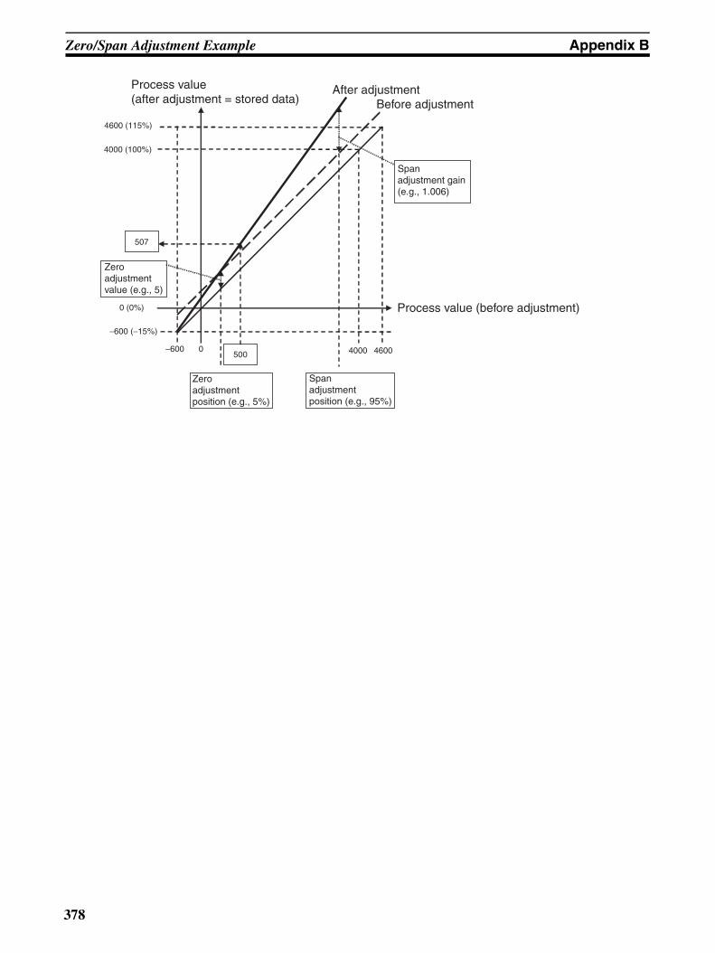
Zero/Span Adjustment Example Appendix B
4600 (115%)
4000 (100%)
0 (0%)
500
507
Process value (after adjustment = stored data)
After adjustmentBefore adjustment
Process value (before adjustment)
Span adjustment position (e.g., 95%)
Zero adjustment position (e.g., 5%)
Zero adjustment value (e.g., 5)
Span adjustment gain (e.g., 1.006)
−600 0
−600 (−15%)
4000 4600
378
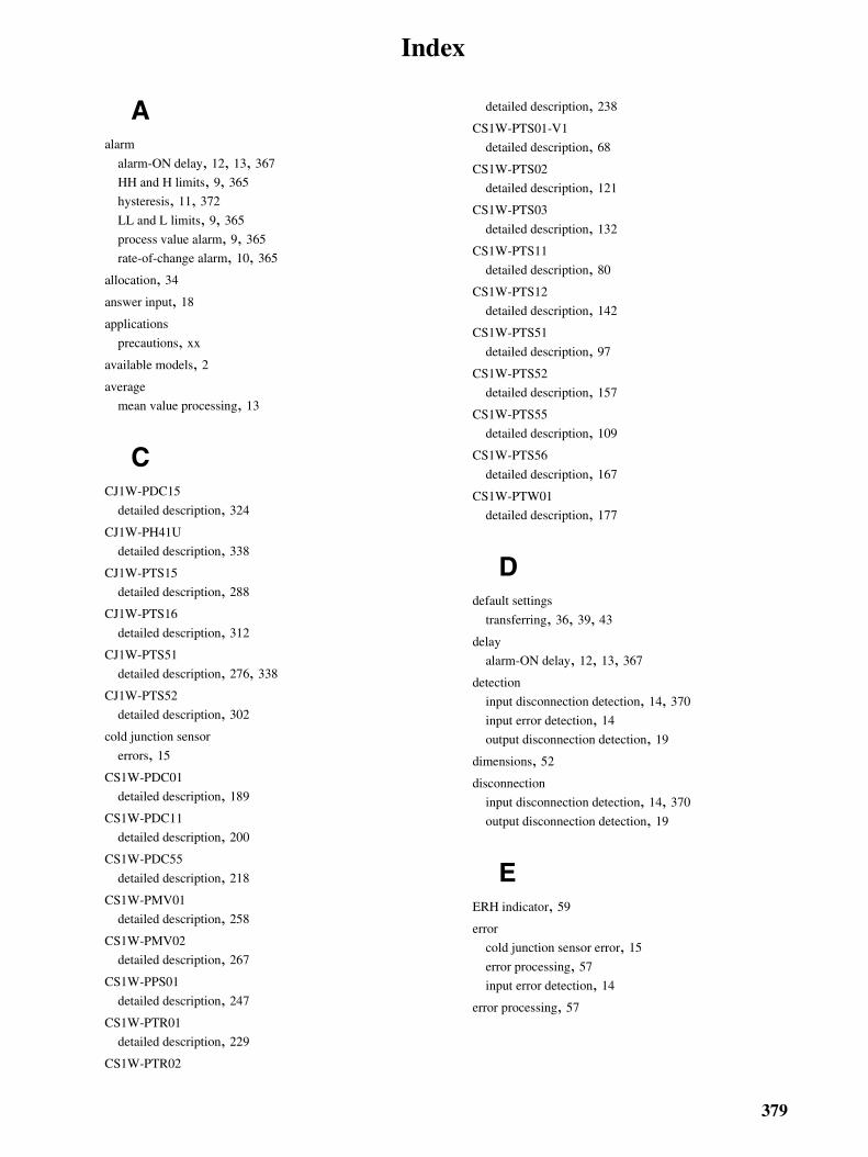
Index
Aalarm
alarm-ON delay, 12, 13, 367
HH and H limits, 9, 365
hysteresis, 11, 372
LL and L limits, 9, 365
process value alarm, 9, 365
rate-of-change alarm, 10, 365
allocation, 34
answer input, 18
applications
precautions, xx
available models, 2average
mean value processing, 13
CCJ1W-PDC15
detailed description, 324
CJ1W-PH41U
detailed description, 338
CJ1W-PTS15
detailed description, 288
CJ1W-PTS16
detailed description, 312
CJ1W-PTS51
detailed description, 276, 338
CJ1W-PTS52
detailed description, 302
cold junction sensor
errors, 15
CS1W-PDC01
detailed description, 189
CS1W-PDC11
detailed description, 200
CS1W-PDC55
detailed description, 218
CS1W-PMV01
detailed description, 258
CS1W-PMV02
detailed description, 267
CS1W-PPS01
detailed description, 247
CS1W-PTR01
detailed description, 229
CS1W-PTR02
detailed description, 238
CS1W-PTS01-V1
detailed description, 68
CS1W-PTS02
detailed description, 121
CS1W-PTS03
detailed description, 132
CS1W-PTS11
detailed description, 80
CS1W-PTS12
detailed description, 142
CS1W-PTS51
detailed description, 97
CS1W-PTS52
detailed description, 157
CS1W-PTS55
detailed description, 109
CS1W-PTS56
detailed description, 167
CS1W-PTW01
detailed description, 177
Ddefault settings
transferring, 36, 39, 43
delay
alarm-ON delay, 12, 13, 367
detection
input disconnection detection, 14, 370
input error detection, 14
output disconnection detection, 19
dimensions, 52
disconnection
input disconnection detection, 14, 370
output disconnection detection, 19
EERH indicator, 59
error
cold junction sensor error, 15
error processing, 57
input error detection, 14
error processing, 57
379

Index
Ffeatures
CJ1W-PDC15, 324
CJ1W-PH41U, 338
CJ1W-PTS15, 288
CJ1W-PTS16, 312
CJ1W-PTS51, 276, 338
CJ1W-PTS52, 302
CS1W-PDC01, 189
CS1W-PDC11, 200
CS1W-PDC55, 218
CS1W-PMV01, 258
CS1W-PMV02, 267
CS1W-PPS01, 247
CS1W-PTR01, 229
CS1W-PTR02, 238
CS1W-PTS01-V1, 68
CS1W-PTS02, 121
CS1W-PTS03, 132
CS1W-PTS11, 80
CS1W-PTS12, 142
CS1W-PTS51, 97
CS1W-PTS52, 157
CS1W-PTS55, 109
CS1W-PTS56, 167
CS1W-PTW01, 177
Hhysteresis, 11, 372
II/O Isolation, 7input disconnection detection, 14, 370
input error detection, 14
input range
variable input range setting, 7inrush input limit, 16, 371
installation, 26
precautions, xx
isolation
I/O isolation, 7
LLED Indicators, 30, 32
Mmean value processing, 13
models
available models, 2mounting Units, 48
Nnomenclature, 28
Ooperating environment
precautions, xix
operating procedures, 55
output disconnection detection, 19
output hold, 19, 371
output rate-of-change limit, 18
Pprecautions
applications, xx
general, xviii
handling precautions, 50
operating environment, xix
safety, xviii
process value
automatic scaling, 8, 367
averaging, 13
process value alarm, 9, 365
pulse accumulation, 18
pulse input instantaneous value conversion, 17
Rrate-of-change alarm, 10, 365
rate-of-change limit, 18
Restart Bits, 36, 40, 43
restarting Special I/O Units, 36, 43
Ssafety precautions
See also precautions
scaling, 8, 367
380

Index
setup
initial hardware setup, 55
initial software setup, 55
span adjustment gain, 16
example, 375
specifications, 26
CJ1W-PDC15, 325
CJ1W-PH41U, 341
CJ1W-PTS15, 290
CJ1W-PTS16, 314
CJ1W-PTS51, 278, 341
CJ1W-PTS52, 303
CS1W-PDC01, 191
CS1W-PDC11, 203
CS1W-PDC55, 219
CS1W-PMV01, 260
CS1W-PMV02, 269
CS1W-PPS01, 249
CS1W-PTR01, 230
CS1W-PTR02, 240
CS1W-PTS01-V1, 70
CS1W-PTS02, 124
CS1W-PTS03, 134
CS1W-PTS11, 83
CS1W-PTS12, 145
CS1W-PTS51, 99
CS1W-PTS52, 158
CS1W-PTS55, 111
CS1W-PTS56, 168
CS1W-PTW01, 178
square root, 15, 372
stepdown rate, 17
system configuration, 24
CJ1W-PDC15, 324
CJ1W-PH41U, 338
CJ1W-PTS15, 288, 338
CJ1W-PTS16, 312
CJ1W-PTS51, 276
CJ1W-PTS52, 302
CS1W-PDC01, 189
CS1W-PDC11, 200
CS1W-PDC55, 218
CS1W-PMV01, 258
CS1W-PMV02, 267
CS1W-PPS01, 247
CS1W-PTR01, 229
CS1W-PTR02, 238
CS1W-PTS01-V1, 68
CS1W-PTS02, 121
CS1W-PTS03, 132
CS1W-PTS11, 80
CS1W-PTS12, 142
CS1W-PTS51, 97
CS1W-PTS52, 157
CS1W-PTS55, 109
CS1W-PTS56, 167
CS1W-PTW01, 177
Tterminals
connecting, 52
Uunit number switches, 31, 33
Vvariable input range setting, 7
Wword allocation, 34
CJ1W-PDC15, 328, 331
CJ1W-PH41U, 349, 355
CJ1W-PTS15, 293, 296
CJ1W-PTS16, 316, 318
CJ1W-PTS51, 281, 283
CJ1W-PTS52, 307, 308
CS1W-PDC01, 193, 195
CS1W-PDC11, 205, 209
CS1W-PDC55, 221, 225
CS1W-PMV01, 262, 263
CS1W-PMV02, 271, 272
CS1W-PPS01, 252, 253
CS1W-PTR01, 232, 234
CS1W-PTR02, 241, 243
CS1W-PTS01-V1, 73, 75
CS1W-PTS02, 126, 128
CS1W-PTS03, 136, 138
CS1W-PTS11, 86, 90
CS1W-PTS12, 147, 150
CS1W-PTS51, 103, 104
CS1W-PTS52, 161, 163
CS1W-PTS55, 114, 117
CS1W-PTS56, 171, 174
CS1W-PTW01, 181, 183
381

Index
Zzero adjustment offset, 16
example, 375
382

Revision History
A manual revision code appears as a suffix to the catalog number on the front cover of the manual.
The following table outlines the changes made to the manual during each revision. Page numbers refer to theprevious version.
Revision code
Date Revised content
1 April 2000 Original production
02 January 2002 “CS1 Series” was changed to “CS Series” and “-V1” was added to the model number CS1W-PTS01 throughout the manual. In addition, the following changes were made.Page 39: Changes made to diagram and notes 1 and 2, and another note added.Page 40: Terminal numbers changedPage 128: Changes made to equations in 3 places.
03 May 2002 Information on the CS1W-PMV02 Isolated-type Analog Output Unit was added throughout the manual.
04 August 2003 “PC” was changed to “PLC” throughout the manual.Changes and additions were made to add the CS1W-PTS11, CS1W-PTS12, and CS1W-PDC11.
05 February 2004 Changes and additions were made to add the CS1W-PTS51/PTS52 and CJ1W-PTS51/PTS52.
06 June 2004 Changes and additions were made to add the CS1W-PTS55/PTS56 and PDC55.
07 March 2005 Changes and additions were made to add the CJ1W-PTS15/PTS16 and PDC15.
08 February 2007 Page v: Added information on notation for general precautions.Page x: Added information on liability and warranty.Page 13: Added a note below the bottom table.Page 23: Added maximum current and total power supplied for the C200HW-PD025 and CS1D-PD025.Pages 55, 93, 152, 271, and 297: Changed the default values for m+4 to m+16.Page 162: Changed word to m+34 in bottom table. Pages 194 and 317: Added “output =” to formula and added “for” to note 2. Pages 196 and 319: Changed the decimal data range for m+38, m+39, m+42, and m+43.Page 210: Added information on input range to square root calculation and modified the equation.Page 211: Changed values for m+4 to m+32.Page 212: Added information on input range for the square root function, changed the decimal data range for m+39 and m+40, and removed setting of 00 to 03 from m+34.Page 213: Modified the description below the table.Page 283: Added “8: mV” to the sensor type for m+34 and m+49.Pages 290 and 312: Added 24-VDC circuit to the top diagram.
09 March 2008 Changes and additions were made to add the CJ1W-PH41U Isolated-type Universal Input Unit.
10 July 2008 Pages 191, 203, 220, and 326: Added maximum input ratings.Page 304: Added input detection current.
Revision code
Cat. No. W368-E1-10
383