cs 450: computer graphics visible surface...
TRANSCRIPT
CS 450: COMPUTER GRAPHICS
VISIBLE SURFACE DETECTIONSPRING 2016
DR. MICHAEL J. REALE

INTRODUCTION
• We’ve talked about drawing surfaces, but what happens when a surface is hidden?
• E.g., at the back of an object, obscured by another surface, etc.
• We need to determine which surfaces (or parts of surfaces) are visible
• Two general categories (which sometimes overlap):
• Object-space approaches deal with objects/primitives themselves
• Image-space approaches deal with projected primitives at pixel level

OVERVIEW
• In this slide deck, we will cover the following approaches:
• Back-face detection
• Depth-buffer/Z-buffer
• A-buffer
• BSP trees
• Octrees
• Ray-casting

BACK-FACE DETECTION

BACK-FACE CULLING
• If the normal is facing away from the camera, then the surface is probably behind an object
• In other words, given a normal N and a view direction V, if:
• …the surface is pointing away from the camera and can be removed
• If we’ve already performed the view transform, we only need look at the z coordinate of the normal:
• Back-face culling = removing polygons that are facing away from the camera
0NV
0zN

BACK-FACE CULLING
• All non-overlapping, convex shapes done!
• Concave shapes may obscure themselves more work to do
• Overlapping shapes (convex or concave) still more work to do
• However, it is always a good preprocessing step to other approaches generally cuts the total number of polygons to render in half

OPENGL FACE CULLING
• To enable or disable face culling in OpenGL:
• glEnable(GL_CULL_FACE);
• glDisable(GL_CULL_FACE);
• Notice I said FACE culling (not back-face culling). In OpenGL, you can specify what you want culled with glCullFace:
• glCullFace(GL_BACK) cull back faces (default)
• glCullFace(GL_FRONT) cull front faces
• glCullFace(GL_FRONT_AND_BACK) cull front AND back faces no faces drawn (but lines/points still drawn)
• To determine front or back looks at winding order:
• COUNTERclockwise front
• Clockwise back

DEPTH-BUFFER/Z-BUFFER

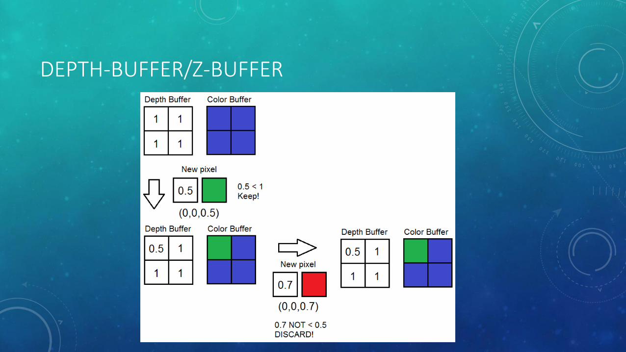
DEPTH-BUFFER/Z-BUFFER
• Depth-buffer/Z-buffer approach
• Pretty much the standard for depth sorting in almost all applications
• Implemented in graphics hardware
• Have depth buffer = separate buffer that holds depth values
• Initialize to 1.0 (remember: normalized device coordinates)
• If projected pixel z < depth[x,y]:
• Depth[x,y] = z
• Color[x,y] = pixel’s color
• Otherwise, ignore pixel
DEPTH-BUFFER/Z-BUFFER

DEPTH-BUFFER/Z-BUFFER
• Advantages:
• Very easy to implement
• For opaque surfaces, does not matter what order they are rendered in!
• Disadvantages:
• Does not work properly with transparent or semi-transparent surfaces (if drawn out of order)
• Can be a little inefficient might already have nearest pixel, but still have to check every other overlapping polygon on that pixel

DEPTH-BUFFER/Z-BUFFER IN OPENGL
• To enable/disable depth-buffer/z-buffer testing in OpenGL:
• glEnable(GL_DEPTH_TEST);
• glDisable(GL_DEPTH_TEST);
• You can also set how the z-buffer works with glDepthFunc()
• When clearing your color buffer, you should also clear out your depth buffer:
• glClear(GL_COLOR_BUFFER_BIT | GL_DEPTH_BUFFER_BIT);

A-BUFFER
A-BUFFER
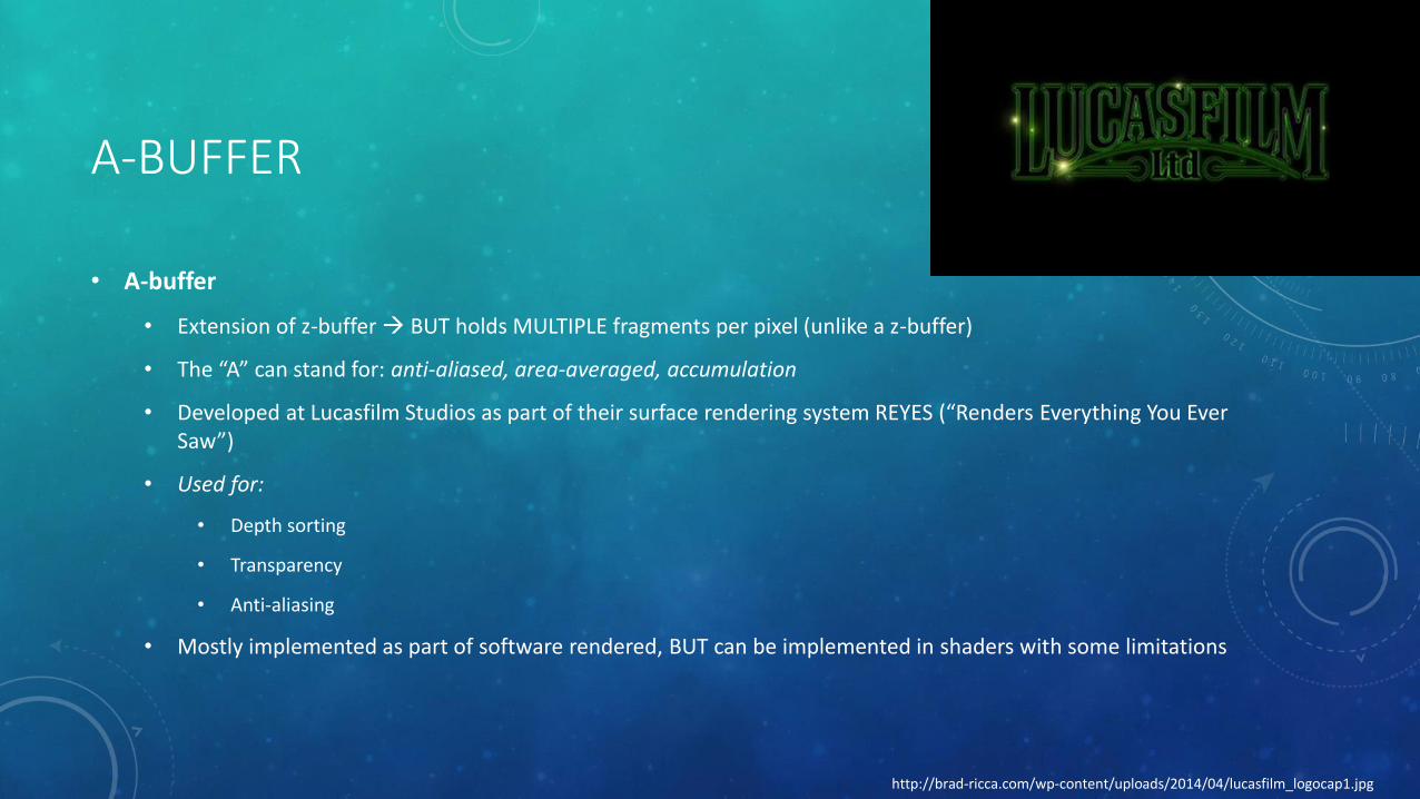
• A-buffer
• Extension of z-buffer BUT holds MULTIPLE fragments per pixel (unlike a z-buffer)
• The “A” can stand for: anti-aliased, area-averaged, accumulation
• Developed at Lucasfilm Studios as part of their surface rendering system REYES (“Renders Everything You Ever Saw”)
• Used for:
• Depth sorting
• Transparency
• Anti-aliasing
• Mostly implemented as part of software rendered, BUT can be implemented in shaders with some limitations
http://brad-ricca.com/wp-content/uploads/2014/04/lucasfilm_logocap1.jpg

A-BUFFER: FRAGMENTS AND PIXELS
• Fragments may only cover PART of a given pixel:
• Each fragment has a coverage mask
• Determines how much of the pixel the fragment actually covers
• Stored as a bit mask
• Fragment’s final color = opacity * (area of coverage mask)
• A-buffer = 2D array of “pixel structs”
• Each pixel struct contains:
• Depth field = stores real-number value (positive, negative, or zero)
• Surface data field = stores surface data OR a pointer
• If (depth field >= 0):
• Depth field = depth of surface
• Surface data field = color (and other info) of fragment
• Otherwise:
• Surface data field = linked list of surface data (RGB, depth, opacity, percent of area coverage, surface identifier, etc.)
• Fragments are often sorted by z-depth
Coverage mask: 0000 0111 1111 0111
Each “pixel struct” in the A-buffer:
Fragment partially covering single pixel:

A-BUFFER: MERGING
• At some point, the list of fragments needs to be merged to get the final color:
• Each fragment determine “inside” and “outside” parts of coverage mask
• Recursively blend list of fragments in these areas
• When merging occurs often tied to how fragments are stored:
• Variable size list
• Can wait until final shading step to merge
• Harder to implement this in hardware/shaders often using software renderer
• Fixed size list
• Can use hardware/shaders (e.g., writing to a texture, using existing z-buffer)
• However, there isn’t really an upper bound on how many fragments overlap a pixel! merge when list is full of fragments (Z3 algorithm)

A-BUFFER VS. OPENGL ACCUMULATION BUFFER
• The buffer used for the A-buffer approach is called an accumulation buffer
• This is NOT to be confused with accumulation buffers in OpenGL, which are implemented as a buffer with a SINGLE color value per pixel
• Do not draw directly into; copy/add whole color buffer into it
• Use glAccum(GLenum op, GLfloat value); values of op:
• GL_ACCUM = read from color buffer, multiply by value, and add to accumulation buffer
• GL_LOAD = same as GL_ACCUM, except it REPLACES the values in the accumulation buffer
• GL_RETURN = takes values from the accumulation buffer, multiplies them by value, and places the result in the color buffer(s) enabled for writing.
• GL_ADD /GL_MULT = simply add or multiply the value of each pixel in the accumulation buffer by value and then return it to the accumulation buffer. For GL_MULT, value is clamped to be in the range [-1.0,1.0]. For GL_ADD, no clamping occurs.
• Can be used for anti-aliasing and motion blur

BSP TREES

BSP TREES
• BSP Trees = Binary Space Partitioning Trees
• Used for depth sorting objects
• Also used for collision detection and intersection calculations (e.g., for ray tracing)
• Two varieties: axis-aligned and polygon-aligned
• Basic idea:
• Use plane to divide space in two
• Sort geometry into these two spaces
• Repeat process recursively
• Traverse trees in a certain way contents sorted from front-to-back from any point of view
• Sorting approximate for axis-aligned and exact for polygon-aligned BSPs

AXIS-ALIGNED BSP TREES
• Enclose whole scene in axis-aligned bounding box (AABB)
• Recursively subdivide that box into smaller boxes
• Splitting plane may split box exactly in half OR may shift a little in position
• Each child box contains some number of objects repeat splitting until some criteria met
• What plane should we use?
• Can cycle through each axis for each plane (first x, then y, then z, then x again, and so on) k-d trees
• OR
• Can pick largest side of box and split along this direction
• Want to avoid splitting objects if possible; if object is split, you can either:
• Store at current level of tree only one copy of object in tree, but not as efficient if small objects get stuck up in upper levels
• Store in both child nodes tighter bounds for larger objects, but objects in multiple locations
AXIS-ALIGNED BSP TREES
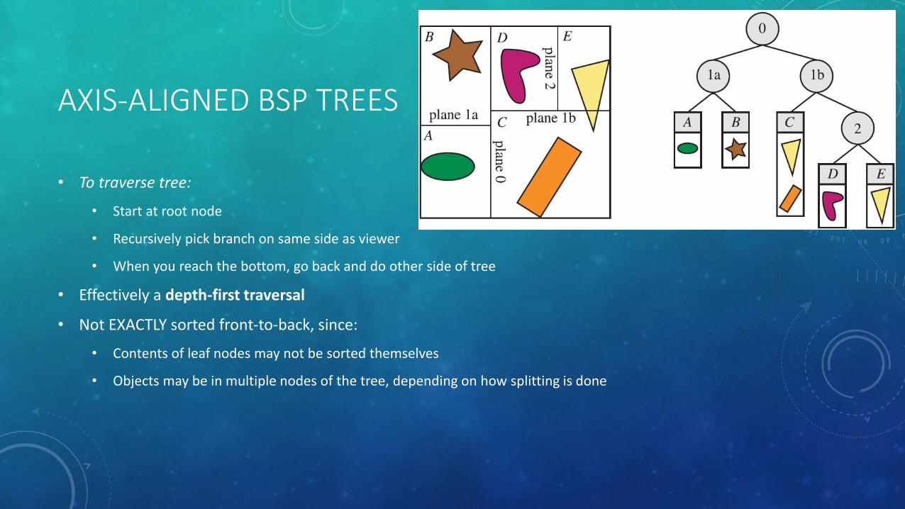
• To traverse tree:
• Start at root node
• Recursively pick branch on same side as viewer
• When you reach the bottom, go back and do other side of tree
• Effectively a depth-first traversal
• Not EXACTLY sorted front-to-back, since:
• Contents of leaf nodes may not be sorted themselves
• Objects may be in multiple nodes of the tree, depending on how splitting is done

POLYGON-ALIGNED BSP TREES
• Particularly useful for rendering static/rigid geometry in an exact sorted order
• Popular for games like Doom, back when there was no hardware Z-buffer
• Still used for collision detection
• Polygons = dividing planes
• Start with one polygon as root
• Divide all other polygons into inside and outside plane of polygon
• If other polygon intersects plane split polygon
• Choose another polygon in each half-space as divider
• Repeat process recursively until all polygons in BSP tree
• Time-consuming process usually create tree once and store for further use
http://vignette2.wikia.nocookie.net/doom/images/b/b3/Imp.png/revision/latest/scale-to-width/256?cb=20050113171050

POLYGON-ALIGNED BSP TREES
• Challenge: ideally want balanced BSP tree i.e., depth of all branches is the same
• Useful property: for a given view, tree can be traversed in strictly back to front (or front to back) order
• Determine on which side the root plane the camera is located
• Go down branch on other side of camera
• Repeat process recursively
• Go back up to other branches when hit bottom

POLYGON-ALIGNED BSP TREES
• Example above (back to front):
• Start at A C on other side
• At C G on other side
• Output G go back up tree
• Output C go down other branch F
• Output F go back up tree
• Go back up to A
• Output A go down other branch B
• At B E on other side
• Output E go back up tree
• Output B go down other branch D
• Output D
• Final drawing order: G, C, F, A, E, B, D

OCTREES

OCTREES
• Octrees
• Similar to axis-aligned BSP tree
• Enclosed entire area in minimal axis-aligned box
• Split simultaneously in all 3 axes split point at center of box makes eight new boxes
• Keep splitting recursively until max depth is reached or have certain number of objects in box
• 3D version of a quadtree:
• Example: split until box is 1) empty or 2) contains only one object

OCTREES
• What if object straddles TWO leaf nodes?
• Option 1) Just store in both leaf nodes
• Option 2) Use smallest box that contains entire object inefficient for a small object in the center of a large node
• E.g., star object in example above
• Option 3) Split objects introduces more primitives
• Option 4) Have pointer to object less efficient and makes editing octree more difficult

OCTREES VS. BSP TREES
• BSP tree can partition things the same way as an octree
• Octree doesn’t need to store additional plane information like BSP trees
• BSP trees can be more efficient because of better splitting

RAY-CASTING

RAY-CASTING
• Ray-casting = shooting a ray from the camera through each position in the projection plane and checking what object(s) we intersect with nearest one is used as color for a pixel
• Alternative (non-real-time) rendering approach
• Works with polygonal objects as well as implicit objects (e.g., F(x,y,z) = 0)
• Must intersect ray with ALL objects in scene and pick nearest point inefficient
• Partial solution: use BSP trees or similar approaches to reduce intersection computations

RAY-CASTING VS. RAY-TRACING
• Ray-casting = shooting ray to nearest object; special case of ray-tracing
• Ray-tracing = traces multiple ray paths to get global reflection, refraction, etc.