cs 356: computer network architectures lecture 6: multi-access … · 2019-01-31 · –multiple...
TRANSCRIPT

CS 356: Computer Network Architectures
Lecture 6: Multi-access links
Chapter 2.6, 2.7, end-to-end arguments
Xiaowei [email protected]

Overview• Sliding window revisited• End-to-end arguments– Reliable transmission
• Multiple access links– Ethernet: CSMA/CD– Token ring–Wireless• 802.11 (WiFi): RTS/CTS• Bluetooth• Cell phone
– Note: understand the concepts

Exercise
• Delay: 100ms; Bandwidth: 1Mbps; Packet Size: 1000 Bytes; Ack: 40 Bytes
• Q: the smallest window size to keep the pipe full?

• Window size = largest amount of unacked data• How long does it take to ack a packet?– RTT = 100 ms * 2 + transmission delay of a packet
(1000B) + transmission delay of an ack (40B) ~=208ms
• How many packets can the sender send in an RTT?– 1Mbps * 208ms / 8000 bits = 26
• Roughly 13 packets in the pipe from sender to receiver, and 13 acks from receiver to sender
100ms
1Mbps
END-TO-END ARGUMENTS IN SYSTEM DESIGN
By J.H. Saltzer, D.P. Reed and D.D. Clark*

End-to-End Argument• Extremely influential
• �…functions placed at the lower levels may be redundant or of little value when compared to the cost of providing them at the lower level…�
• �…sometimes an incomplete version of the function provided by the communication system (lower levels) may be useful as a performance enhancement…�
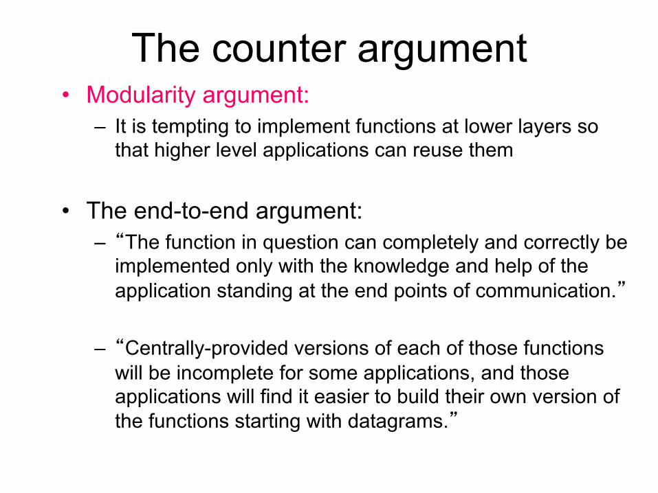
The counter argument• Modularity argument:
– It is tempting to implement functions at lower layers so that higher level applications can reuse them
• The end-to-end argument:– �The function in question can completely and correctly be
implemented only with the knowledge and help of the application standing at the end points of communication.�
– �Centrally-provided versions of each of those functions will be incomplete for some applications, and those applications will find it easier to build their own version of the functions starting with datagrams.�
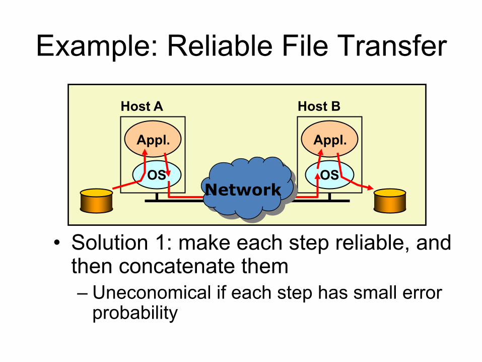
Example: Reliable File Transfer
• Solution 1: make each step reliable, and then concatenate them– Uneconomical if each step has small error
probability
OS
Appl.
OS
Appl.
Host A Host B
Network

Example: Reliable File Transfer
• Solution 2: end-to-end check and retry– Correct and complete
OS
Appl.
OS
Appl.
Host A Host B
OKNetwork

Example: Reliable File Transfer
• An intermediate solution: the communication system provides internally, a guarantee of reliable data transmission, e.g., a hop-by-hop reliable protocol– Only reducing end-to-end retries– No effect on correctness
OS
Appl.
OS
Appl.
Host A Host B
OKNetwork

Question: should lower layer play a part in obtaining reliability?
• Answer: it depends– Example: extremely lossy link
• One in a hundred packets will be corrupted• 1K packet size, 1M file size• Prob of no end-to-end retry: (1-1/100)1000 ~ 4.3e-5
• TCP provides a reliable bitstream interface

Performance enhancement
• �put into reliability measures within the data communication system is seen to be an engineering tradeoff based on performance, rather than a requirement for correctness.�
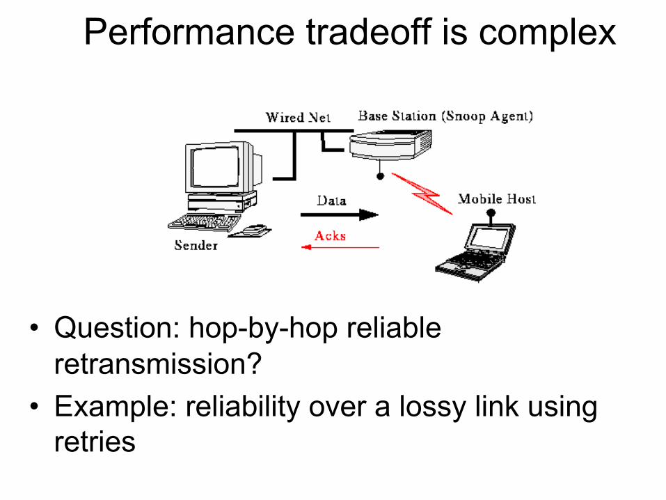
Performance tradeoff is complex
• Question: hop-by-hop reliable retransmission?
• Example: reliability over a lossy link using retries

Performance tradeoffs• Example: reliability over a lossy link using retries
– But they wont help real time applications, applications with built-in error correction mechanisms
• Tradeoffs:– Applications that do not need them will pay the cost
anyway– Low-level subsystems may not have as much
information as the higher levels to do the job as efficiently

End-to-End Argument: Discussion• The original end-to-end argument emphasizes
correctness & completeness, not – complexity: is complexity at edges result in a �simpler� architecture?
– evolvability, ease of introduction of new functionality: ability to evolve because easier/cheaper to add new edge applications than change routers?
– Technology penetration: simple network layer makes it �easier� for IP to spread everywhere

Summary: End-to-End Arguments
• If the application can do it, don�t do it at a lower layer -- anyway the application knows the best what it needs– add functionality in lower layers iff it is (1)
used and improves performances of a large number of applications, and (2) does not hurt other applications
• Success story: Internet– a minimalist design
Overview• Sliding window revisited• End-to-end arguments– Reliable transmission
• Multiple access links– Ethernet: CSMA/CD– Token ring–Wireless• 802.11 (WiFi): RTS/CTS• Bluetooth• Cell phone
– Note: understand the concepts

Original design• 802.3 standard defines both MAC and physical
layer details– No switches
Robert Metcalfe�s originalEthernet SketchHe identified the day Ethernet was born as 05/22/1973

Multiple-access links
• Many nodes attached to the same link– Ethernet– Token rings– Wireless network (WiFi)
• Problem: who gets to send a frame?– Multiple senders lead to collision
• Solution: a general technique– Multiple access with collision detect (CSMA/CD)
•Bus LAN •Ring LAN
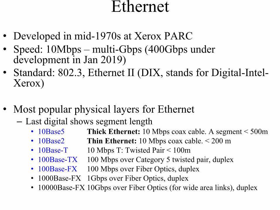
Ethernet• Developed in mid-1970s at Xerox PARC• Speed: 10Mbps – multi-Gbps (400Gbps under
development in Jan 2019)• Standard: 802.3, Ethernet II (DIX, stands for Digital-Intel-
Xerox)
• Most popular physical layers for Ethernet– Last digital shows segment length
• 10Base5 Thick Ethernet: 10 Mbps coax cable. A segment < 500m• 10Base2 Thin Ethernet: 10 Mbps coax cable. < 200 m• 10Base-T 10 Mbps T: Twisted Pair < 100m• 100Base-TX 100 Mbps over Category 5 twisted pair, duplex• 100Base-FX 100 Mbps over Fiber Optics, duplex• 1000Base-FX 1Gbps over Fiber Optics, duplex• 10000Base-FX 10Gbps over Fiber Optics (for wide area links), duplex
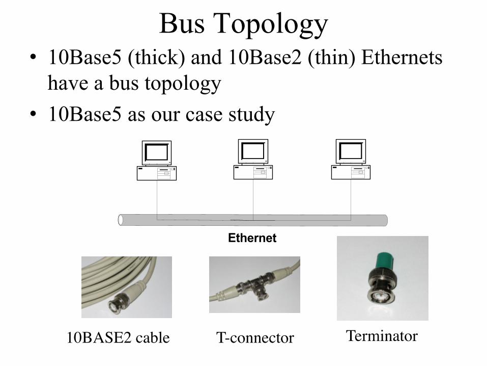
Bus Topology
Ethernet
• 10Base5 (thick) and 10Base2 (thin) Ethernets have a bus topology
• 10Base5 as our case study
10BASE2 cable T-connector Terminator

Physical propertiesSensing the line; if idle, sends signals
10Base5
Transceiverq A small device directly
attached to the tapq It detects when the
line is idle and drives the signal when the host is transmitting
q It also receives incoming signals.

How to expand an Ethernet segment• A repeater is a device that
forwards digital signals– Multiple segments can be
joined together by repeaters
• No more than four repeaters between any host– <2500 meters
• < 1024 hosts• Terminators are attached to
each end of the segment• Manchester encoding

• Starting with 10Base-T, stations are connected to a hub (or a switch) in a star configuration
• 100Mbps, 1000Mbps
How to expand an Ethernet segment (II)
Hub
10 Base-T cable and jackA hub is a multiwayrepeater
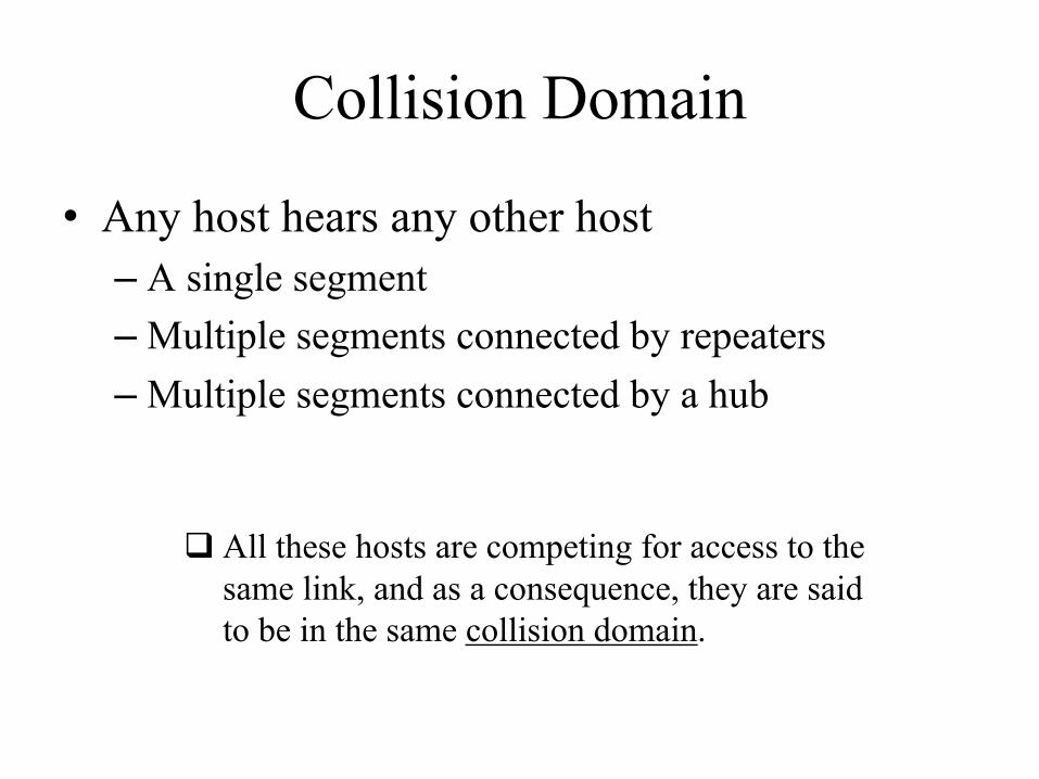
Collision Domain
• Any host hears any other host– A single segment–Multiple segments connected by repeaters–Multiple segments connected by a hub
q All these hosts are competing for access to the same link, and as a consequence, they are said to be in the same collision domain.

Access control
• Bit-oriented framing• In a host�s memory, Ethernet header is 14 bytes• The adaptor adds the preamble and CRC• The type field is the de-multiplexor
• 46-1500 bytes of data– Pad to minimum length– Minimum length is for collision detection
• 802.3 has the same header format, but substitutes type with length field– How to tell whether the field indicates type or length?
• All types > 1500B

A prettier picture
• You�ll need to know this for Lab 2
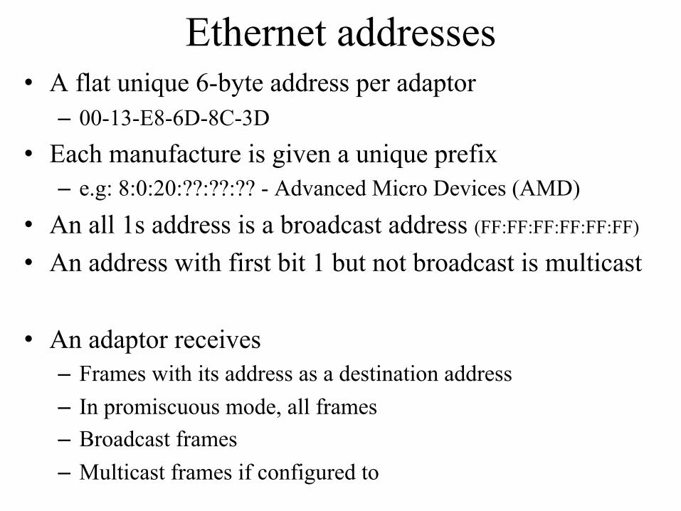
Ethernet addresses• A flat unique 6-byte address per adaptor– 00-13-E8-6D-8C-3D
• Each manufacture is given a unique prefix– e.g: 8:0:20:??:??:?? - Advanced Micro Devices (AMD)
• An all 1s address is a broadcast address (FF:FF:FF:FF:FF:FF)
• An address with first bit 1 but not broadcast is multicast
• An adaptor receives – Frames with its address as a destination address– In promiscuous mode, all frames– Broadcast frames– Multicast frames if configured to

Transmitter Algorithm (1)
1. The adaptor receives datagram from network layer, creates frame
2. If the adaptor senses channel idle, starts frame transmission. If NIC senses channel busy, waits until channel idle, then transmits.
3. If NIC transmits an entire frame without detecting another transmission, NIC is done with frame!
4. If NIC detects another transmission while transmitting, abortsand sends jam signal (collision!!)

Transmitter Algorithm (2)
• If collision…– jam for 32 bits, then stop transmitting frame–Wait and try again• exponential backoff (doubling the delay interval of
each collision)• After the nth collision:: the adaptor waits for k x
51.2us, for randomly selected k=0, …, 2n – 1– 1st time: 0 or 51.2us– 2nd time: 0, 51.2, 102.4, or 153.6us–…
• give up after several tries (usually 16)

Carrier Sense Multiple Access with Collision Detection (CSMA/CD)
• An adaptor senses the signals on the line and compares it with its own– If same, no collision; otherwise, collision– Sends 32-bit jamming sequence after collision
• In the worst case, a sender needs to send 512 bits (46+14+4 = 64B) to detect collision– Why?

q A and B are at opposite ends of the networkq One way delay is dq A needs to send for 2d (round-trip delay) to detect collisionq 2d = 51.2 μs. On a 10Mps Ethernet, corresponds to 512 bits
q Related to maximum Ethernet length ~ 2500 mq Has some margin for errors
(a) A sends a frame at time t ;
(d) B’s runt (32-bit) frame arrives at A at time t + 2d.
(c) B begins transmitting at time t + d and immediately collides with A’s frame;
(b) A’s frame arrives at B at time t + d;

• The IEEE 802.3 Baseband 5-4-3 – Five physical segments between any two nodes– Four repeaters between the nodes. – Three of these physical segments can have connected node
• Each segment < 500m à Total < 2500m

• Propagation delay for this maximum-extent Ethernet network is 25.6us
• 2*d = 51.2us• Minimum Ethernet packet frame is 512 bits
(64B)– Header 14B, payload 46B, CRC 4B
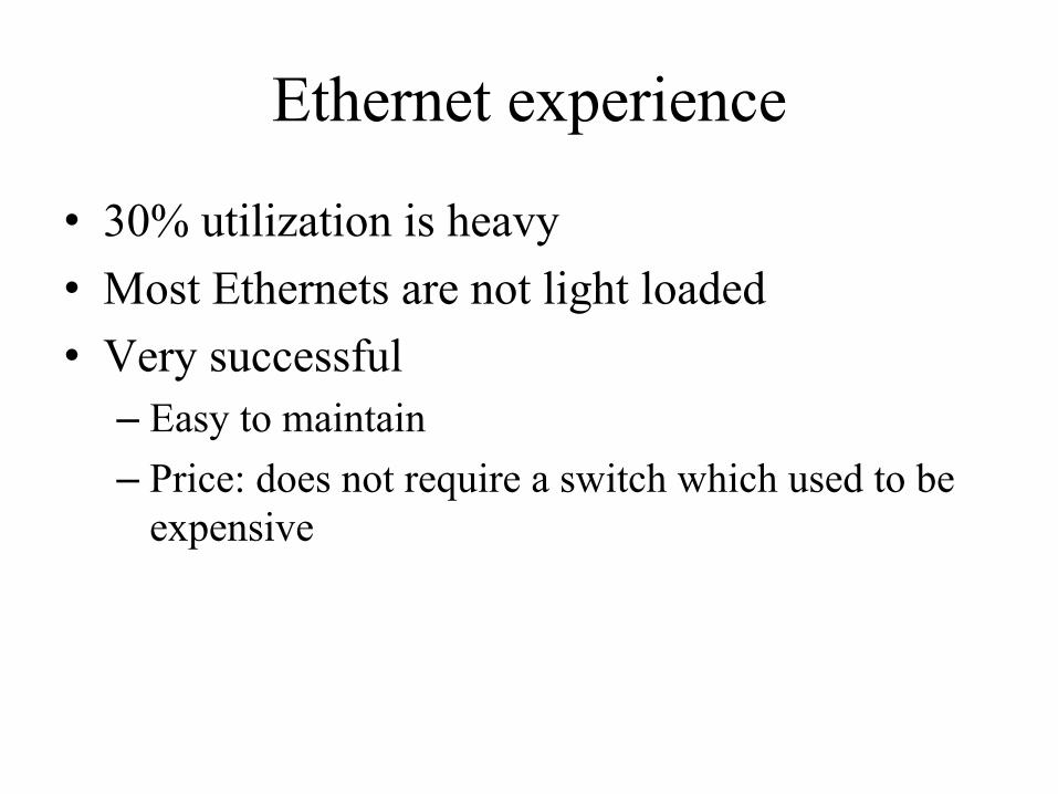
Ethernet experience
• 30% utilization is heavy• Most Ethernets are not light loaded• Very successful– Easy to maintain– Price: does not require a switch which used to be
expensive

Overview• Sliding window revisited• End-to-end arguments– Reliable transmission
• Multiple access links– Ethernet: CSMA/CD– Token ring–Wireless• 802.11 (WiFi): RTS/CTS• Bluetooth• Cell phone
– Note: understand the concepts

Token rings• A token circulates the ring
• If a node has something to send, take the token off the ring, and send the frame– Node 1
• Each node along the way simply forwards the frame
• Receiver copies the frame– Node 4
• Frame comes back to sender – Sender removes the packet
and puts the token back

Token ring standard
• IBM Token Ring• A nearly identical IEEE standard– 802.5: not widely used
• Fiber Distributed Data Interface (FDDI)– Derived from the IEEE 802.4 token bus timed
token protocol
• Resilient Packet Ring (RPR)– 802.17

Challenges must be addressed
• Fault tolerance
• Media access control– How long each node can hold the token?
• Reliability– How does the sender know the frame is received
• Resource utilization

Adding fault tolerance
• Problem: single node powers off disconnects the ring
• Solution: relay that closes when host�s powered off
an electromechanical relay

Token ring media access control• An adaptor has a receiver and a transmitter• Problem: how long can a node holds a token? – Token holding time (THT), default 10ms in 802.5– Short: waste bandwidth– Long: starve others–What if you have an important short message?

802.5 Token Access Protocol• A token has a 3-bit priority field• A frame has three reservation bits– A device seizes the token if its packet’s priority is
at least as the token– Reservation• A sender X sets priority n in the three reservation bits in
a frame if– The bits are not set to a higher value
• The station that holds the token set priority to n– Sender X lowers the token priority after releasing
it so other senders can send– Drawback: may starve lower priority traffic

Token ring reliability
• No sliding window!
• Two trailing bits (A, C) after each frame– A recipient sets A bit when it sees the frame– Sets C bit after it copies the frame back to its adaptor– If a sender does not see both bits set, retransmits
q A=0, C=0: the intended recipient is not functioning or absentq A=1, C=0: for some reason (e.g., lack of buffer space), the
destination could not accept the frameq A=1, C=1: frame received

When to release a token
• Which one is better?– 802.5 originally used (b), and adds (a) later
Early release:Sender inserts the token back onto the ring immediately following its frame
Late release:Sender inserts the token after the frame it transmits has gone all the way around the ring and been removed
Better bandwidth utilization

802.5 Token ring maintenance
• A monitor makes sure the token is not lost– Periodically announces itself
• If the monitor fails– A station elects itself by sending a claim token– If the token comes back, it�s the monitor– If competition, highest address wins
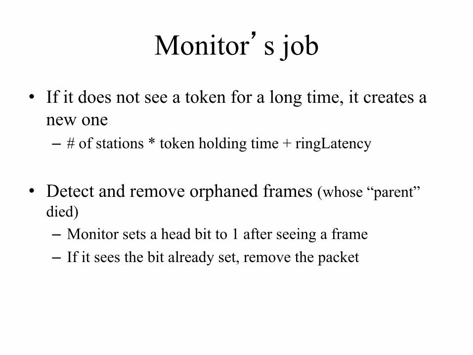
Monitor�s job
• If it does not see a token for a long time, it creates a new one– # of stations * token holding time + ringLatency
• Detect and remove orphaned frames (whose “parent” died)– Monitor sets a head bit to 1 after seeing a frame– If it sees the bit already set, remove the packet

802.5 Frame format
q Similar to the Ethernet, 802.5 addresses are 48 bits long.
q The frame also includes a 32-bit CRC.q Frame status byte includes the A and C bits for
reliable delivery

Wireless links
• Most common– Asymmetric
• Point-to-multipoint

Wireless access control
• Can’t use Ethernet protocol– Hidden terminal• A and C can�t hear each other�s collision at B
– Exposed terminal• B can send to A; C can send to D

802.11 (WiFi) Multiple access with collision avoidance (CSMA/CA)
• Sender and receiver exchange control– Sender à receiver: Request to send (RTS)
• Specifies the length of frame– Receiver à sender: Clear to send (CTS)
• Echoes length of frame– Sender à receiver: frame– Receiver à sender: ack– Other nodes can send after hearing ACK
• Node sees CTS– Too close to receiver, can�t transmit– Addressing hidden terminals
• Node only sees RTS– Okay to transmit– Addressing exposed terminals

How to resolve collision
• Sender cannot do collision detection– Single antenna can�t send and receive at the same
time
• If no CTS, then RTS collide• Exponential backoff to retransmit

Distribution system
• Hosts associate with APs• APs connect via the distribution system – A layer-2 system
• Ethernet, token ring, etc.
– Host IP addresses do not need to change
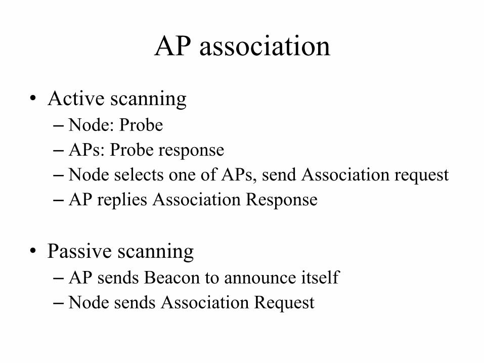
AP association
• Active scanning– Node: Probe– APs: Probe response– Node selects one of APs, send Association request– AP replies Association Response
• Passive scanning– AP sends Beacon to announce itself– Node sends Association Request

Frame format
• Same AP– Addr1: dst– Addr2: src
• Different Aps– ToDS and FromDS in control field set– Add1: dst, Addr2: AP_dst– Addr3: AP_src, Add4: src

Bluetooth
• Connecting devices: mobile phones, headsets, keyboards– Very short range communication– Low power
• License exempt band 2.45 Ghz• 1~3Mpbs• Specified by Bluetooth Special Interest Group

A bluetooth piconet
• A master device and up to seven slave devices• Communication is between the master and a slave

Cell phone technologies
• Using licensed spectrum• Different bands using different frequencies• Base stations form a wired network• Geographic area served by a base station’s
antenna is called a cell– Similar to wifi
• Phone is associated with one base station• Leaving a cell entering a cell causes a handoff

Cellular technologies
• 1G: analog• 2G: digital and data• 3G: higher bandwidth and simultaneous voice
and data• 4G: even higher. Top around 2.6Ghz• 5G: 15Ghz

Summary• A new reliable transmission mechanism– Current logical channels
• Multiple access links– Ethernet– 802.11 (WiFi)– Bluetooth– Cell phone– Note: understand the concepts

Backup

Transmitter Algorithm
Begin: Wait until the line is idle and has data to send, the adaptor sends it, and listens to collision– If no, go back to Begin– else exponentially backoff• randomly selects a k between [0,2n-1], waits for k x
51.2 µs to try Begin again
• Gives up after n reaches 16
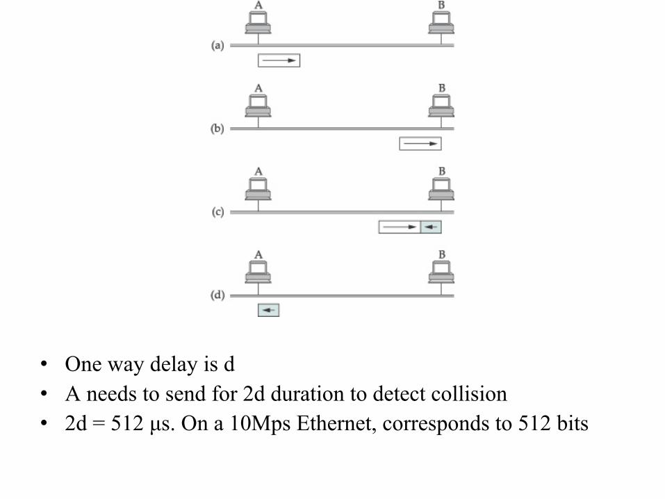
• One way delay is d• A needs to send for 2d duration to detect collision• 2d = 512 µs. On a 10Mps Ethernet, corresponds to 512 bits