cryogenic optical performance of a lightweighted mirror
TRANSCRIPT
Cryogenic optical performance of a lightweighted mirror assembly for future space astronomical telescopes: correlating optical test results
and thermal optical model Ron Eng*a, William R. Arnolda, Marcus A. Bakera, Ryan M. Bevanab, Gregory Burdickc, Michael R.
Effingera, Darrell E. Gaddya, Brian K. Goodea, Craig Hansonc, William D. Hoguea, Jeffrey R. Kegleya, Charlie Kirkc, Steven P. Maffettc, Gary W. Matthewsd, Richard D. Silera, W. Scott Smitha,
H. Philip Stahla, John M. Tuckera, Ernest R. Wrighta, aNASA Marshall Space Flight Center, Huntsville, AL, USA 35812;
bThe University of Alabama in Huntsville, Huntsville, AL, USA 35899; cITT Exelis Geospatial Systems, 800 Lee Rd, Rochester, NY, USA 03115;
d ITT Exelis, Greenbelt, MD, USA 20771
ABSTRACT
A 43cm diameter stacked core mirror demonstrator was interferometrically tested at room temperature down to 250 degrees Kelvin for thermal deformation. The 2.5m radius of curvature spherical mirror assembly was constructed by low temperature fusing three abrasive waterjet core sections between two CNC pocket milled face sheets. The 93% lightweighted Corning ULE® mirror assembly represents the current state of the art for future UV, optical, near IR space telescopes. During the multiple thermal test cycles, test results of interferometric test, thermal IR images of the front face were recorded in order to validate thermal optical model. Keywords: Lightweighted ULE® mirror, optical testing, optical model
1. INTRODUCTION
In a 2012 National Research Council report, NASA Space Technology Roadmaps and Priorities, the committee identified 14 space technology areas (TA) and roadmap for advancing space technology research and development over the next 3 decades. Space technology area TA08, Science Instruments, Observatories, and Sensor Systems, its roadmap addressed technologies for future space missions relevant to Earth science, heliophysics, planetary science, and astrophysics driven by science and mission priorities recommended in the 2010 decadal survey of astronomy and astrophysics in New Worlds, New Horizons in Astronomy and Astrophysics. The TA08 committee identified low cost, high performance telescopes as one of the top technical challenges. The technology will be used to develop the next generation of large-aperture astronomical telescopes to detect elusive extrasolar planets, or exoplanets such as Earth-analogs. Earth-analogs are earth-sized worlds circling around a star similar to our sun. Larger aperture telescopes is needed to help answer age old question, such as whether there are life on these exoplanets. In addition, larger telescopes can be used for lightweighted, laser communication systems, and high-performance orbiting observatories for understanding how galaxies assemble their stellar populations, understanding the interactions of baryonic matter with intergalactic medium, and further understanding our earth formation and evolution in our own solar system. Large aperture, lightweighted, high stiffness mirrors, both monolithic 4 to 8 meters, and segmented mirrors greater than 8 meters, were identified as a high priority technology for future UV, visible, and IR orbiting observatories. Since large mirror development programs are inherently prohibitively costly from design, manufacturing, fabrication, to testing, an integrated modeling software for the mirror technology would be necessary to validate the mirror system before cutting any hardware since cost of mirror materials, labor to manufacture the mirror system, and optical testing in relevant environment such as vacuum and cryogenic temperatures involves materials, labor hours and test facilities costs.
In response to these findings and the current federal budget constraints to do more science with less funding, NASA funded the Advanced normal incidence ultraviolet/optical/near-infrared (UVOIR) Mirror Technology Development (AMTD) Program for Very Large Space Telescopes. The key objectives of the AMTD program is to define and initiate a long-term program to mature lower cost, large aperture, low areal density, high stiffness primary mirror substrate to technology readiness level 6 (TRL-6) by 2018 so that a viable flight observatory mission can be proposed to the 2020
Decadal Review. Another key element of the AMTD program is the integrated model validation of optical performance determined by mechanical and thermal models to validate representative mirror prototypes. ITT Exelis was partnered to develop a 40cm diameter proof of concept demonstration mirror scalable to 4 meters mirror or larger using the stacked core technology.
2. STACKED CORE MIRROR TECHNOLOGY
The primary mirror for the Hubble Space Telescope was a lightweighted mirror fabricated out of Corning 7941 Ultra-Low Expansion (ULE®) titania-silica glass; its diameter was 2.49m with 30.5cm thick with a central hole of 71.1cm. The front and back facesheets are 2.54cm thick, stacked between a lightweighted core. The Hubble primary mirror weights 828kg, and it is ~25% of the equivalent solid ULE® structure. The areal density for the Hubble primary mirror is 180 kg/m2.
ULE® is well suited for both large ground and space astronomical telescope mirrors due to its low thermal expansion, thermal conductivity and diffusivity, density, and high temporal and thermal stability. The near zero coefficient of thermal expansion (CTE) is the most important property for large mirrors with axial or radial thermal gradients.
The Corning Canton plant was facilitized to manufacture up to 8+meter ULE® boule. Corning supplied the ULE® blank for the 4.3m diameter primary mirror for Discovery Channel Telescope in 2005. The Discovery Channel telescope was recently completed at Happy Jack, AZ. Corning casted several 8.2m ULE® mirror blanks for the Subaru, Gemini North, and Gemini South Telescopes. Corning pioneered the manufacturing process to use abrasive waterjet to minimize intercell rib thickness while maintaining high structural dimensional stability. Combining abrasive waterjet, frit bonding or low temperature fusion bonding techniques, core structure can achieve 2% density or 98% lightweighting. The mirror assembly can be sagged or slumped over a mandrel to form a meniscus, near-net shape mirror. Recent efforts at Corning have reduced the striae in each boule in order to reduce striae induced mid-spatial frequency roughness for UV missions.
Exelis developed a 43cm diameter, 2.5m radius of curvature, UV quality, low areal density, thermally and dynamically stable proof of concept mirror scalable to 4m or larger. The mirror was constructed with 1.56cm and 1.7cm thick front and back factsheets fused between 3 lightweighted cores with total core thickness of 33.44cm. The stacked core mirror assembly weights 6.7kg; and it is ~7% or 93% lightweighting of the equivalent solid Corning 7972 ULE® structure. The areal density for the stacked core mirror can be scalable to 35 kg/m2.
During the Hubble primary mirror assembly, high temperature fusion technique was used to fuse lightweighted core with ribs section to the front and back facesheets. The Exelis 43cm stacked core mirror demonstrator was fabricated by low temperature fusing 2 pocket milled plano facesheets to 3 abrasive waterjet core sections. The stacked core mirror assembly method reduces risk and cost of the catastrophic failure during the ULE® cores abrasive waterjet lightweighting process, yet maintaining its stiffness after assembly. The core depth and rib thickness were optimized for minimal quilting during cryogenic testing and areal density. The stacked core fabrication method eliminates the need for lightweighting very thick solid ULE® boule by abrasive waterjet. Three cores with thickness of less than 15cm were processed by abrasive waterjet. Experimental results have proven specialized abrasive waterjet can cut depth up to 40cm for larger diameter mirror core sections.
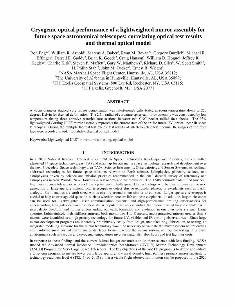
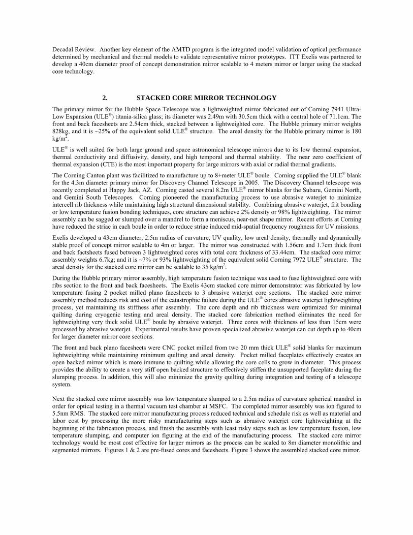
The front and back plano facesheets were CNC pocket milled from two 20 mm thick ULE® solid blanks for maximum lightweighting while maintaining minimum quilting and areal density. Pocket milled faceplates effectively creates an open backed mirror which is more immune to quilting while allowing the core cells to grow in diameter. This process provides the ability to create a very stiff open backed structure to effectively stiffen the unsupported faceplate during the slumping process. In addition, this will also minimize the gravity quilting during integration and testing of a telescope system. Next the stacked core mirror assembly was low temperature slumped to a 2.5m radius of curvature spherical mandrel in order for optical testing in a thermal vacuum test chamber at MSFC. The completed mirror assembly was ion figured to 5.5nm RMS. The stacked core mirror manufacturing process reduced technical and schedule risk as well as material and labor cost by processing the more risky manufacturing steps such as abrasive waterjet core lightweighting at the beginning of the fabrication process, and finish the assembly with least risky steps such as low temperature fusion, low temperature slumping, and computer ion figuring at the end of the manufacturing process. The stacked core mirror technology would be most cost effective for larger mirrors as the process can be scaled to 8m diameter monolithic and segmented mirrors. Figures 1 & 2 are pre-fused cores and facesheets. Figure 3 shows the assembled stacked core mirror.
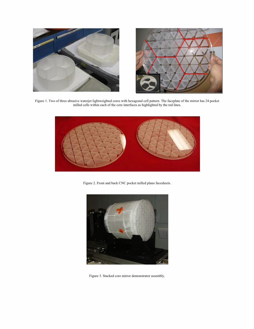
Figure 1. Two of three abrasive waterjet lightweighted cores with hexagonal cell pattern. The faceplate of the mirror has 24 pocket milled cells within each of the core interfaces as highlighted by the red lines.
Figure 2. Front and back CNC pocket milled plano facesheets.
Figure 3. Stacked core mirror demonstrator assembly.
3. CRYOGENIC OPTICAL TESTING SYSTEMS
The X-Ray Cryogenic Facility (XRCF) at the NASA Marshall Space Flight Center has been testing cryogenic normal incidence mirrors since 1998. Prior to 1998, the grazing incidence telescope assembly for the Chandra X-Ray Observatory was tested at the same facility. The James Webb Space Telescope primary mirror segments were cryogenic tested from room temperature down to 25°K in the 3.3 x 10m vacuum chamber in 2010-2011. The facility is equipped with two closed loop gaseous Helium refrigerators, Linde 1620S helium refrigerators. The stacked core mirror thermal optical performance test was performed in the 1 x 3 m cryogenic vacuum test chamber at the X-Ray Cryogenic Facility (XRCF) at the NASA Marshall Space Flight Center. This smaller chamber is more cost effective for testing smaller diameter mirrors with shorter radius of curvature. This smaller chamber contains a gaseous helium cooled inner shroud. An optical window located on the chamber dome allows testing the test article with optical axis-horizontal in vacuum inside the chamber. An optional window can be mounted at the top of the chamber for optical axis-vertical test configurations. The chamber contains a rail system to allow easy positioning of the test article inside the shroud. Figure 4 shows photo of the stacked core mirror on the test stand within the cryo-vac test chamber shroud, prior to positioning and the test chamber closeout.
Figure 4. Stacked core mirror assembly in the 1 x 3m vacuum chamber.
The cryo-vac test chamber cooling is provided by a Helium Compressor/Refrigerator system, Linde Model 1620S helium gas refrigerator supplied by a vertical screw compressor. Liquid nitrogen is supplied to the helium refrigerator precooler by the facility LN2 system. The LN2 system is a closed loop system supplying from and returns to the external storage vessels. A 75 gpm LN2 pump provides LN2 from the two external storage vessels to the helium refrigerator. Twenty-four thermal sensors were used to provide an accurate temperature readout and record the test article and chamber temperature profile during the test. Twelve sensors were attached to the mirror and remaining sensors were located on the helium shroud and test stand in the chamber. The thermal sensors were attached to the mirror and stand with double-sided tape and covered with Kapton tape. Table 1 lists the sensor identifications and descriptions. Figure 5 shows the sensor positions and identifications for the data system. A thermal data system provides real-time display of the data graphically or in tabular form. The temperature data are recorded and retrievable in 30 second intervals.
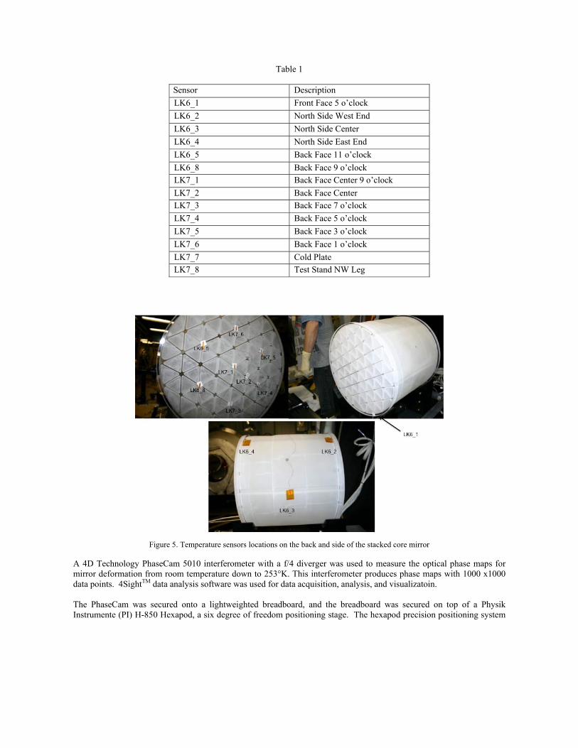
Table 1
Sensor Description
LK6_1 Front Face 5 o’clock
LK6_2 North Side West End
LK6_3 North Side Center
LK6_4 North Side East End
LK6_5 Back Face 11 o’clock
LK6_8 Back Face 9 o’clock
LK7_1 Back Face Center 9 o’clock
LK7_2 Back Face Center
LK7_3 Back Face 7 o’clock
LK7_4 Back Face 5 o’clock
LK7_5 Back Face 3 o’clock
LK7_6 Back Face 1 o’clock
LK7_7 Cold Plate
LK7_8 Test Stand NW Leg
Figure 5. Temperature sensors locations on the back and side of the stacked core mirror
A 4D Technology PhaseCam 5010 interferometer with a f/4 diverger was used to measure the optical phase maps for mirror deformation from room temperature down to 253°K. This interferometer produces phase maps with 1000 x1000 data points. 4SightTM data analysis software was used for data acquisition, analysis, and visualizatoin. The PhaseCam was secured onto a lightweighted breadboard, and the breadboard was secured on top of a Physik Instrumente (PI) H-850 Hexapod, a six degree of freedom positioning stage. The hexapod precision positioning system
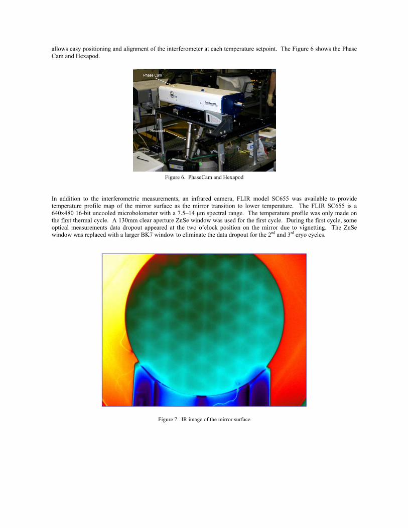
allows easy positioning and alignment of the interferometer at each temperature setpoint. The Figure 6 shows the Phase Cam and Hexapod.
Figure 6. PhaseCam and Hexapod
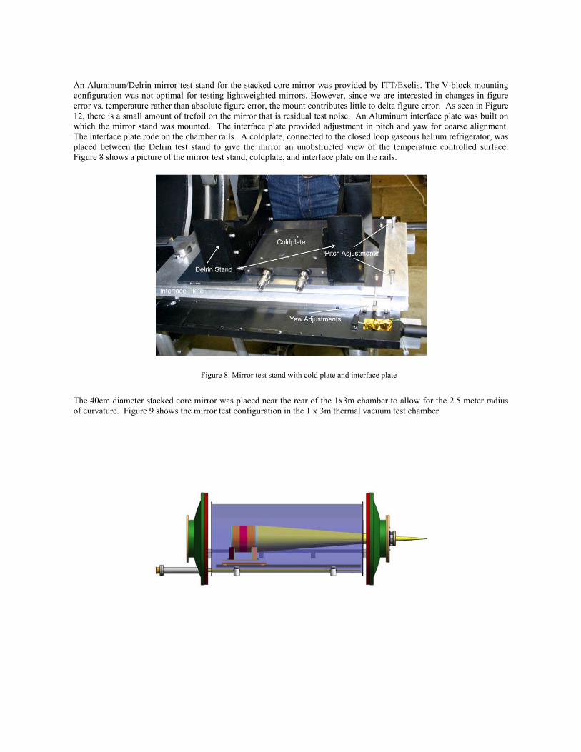
In addition to the interferometric measurements, an infrared camera, FLIR model SC655 was available to provide temperature profile map of the mirror surface as the mirror transition to lower temperature. The FLIR SC655 is a 640x480 16-bit uncooled microbolometer with a 7.5–14 μm spectral range. The temperature profile was only made on the first thermal cycle. A 130mm clear aperture ZnSe window was used for the first cycle. During the first cycle, some optical measurements data dropout appeared at the two o’clock position on the mirror due to vignetting. The ZnSe window was replaced with a larger BK7 window to eliminate the data dropout for the 2nd and 3rd cryo cycles.
Figure 7. IR image of the mirror surface
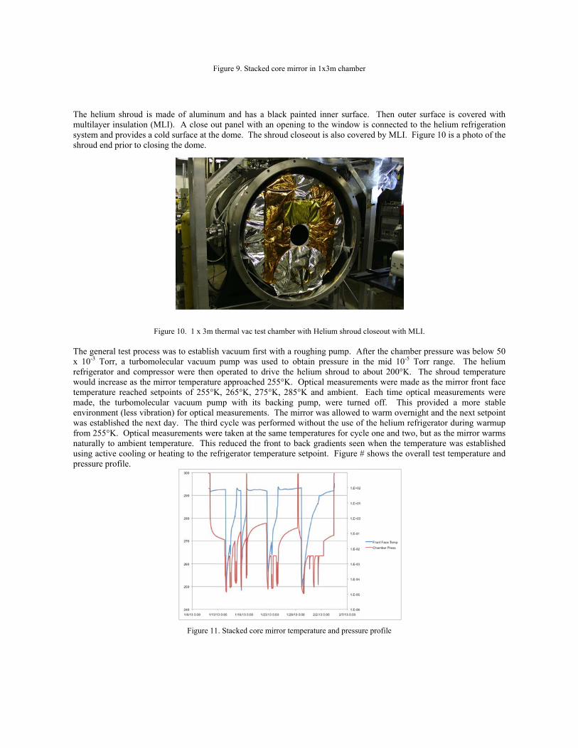
An Aluminum/Delrin mirror test stand for the stacked core mirror was provided by ITT/Exelis. The V-block mounting configuration was not optimal for testing lightweighted mirrors. However, since we are interested in changes in figure error vs. temperature rather than absolute figure error, the mount contributes little to delta figure error. As seen in Figure 12, there is a small amount of trefoil on the mirror that is residual test noise. An Aluminum interface plate was built on which the mirror stand was mounted. The interface plate provided adjustment in pitch and yaw for coarse alignment. The interface plate rode on the chamber rails. A coldplate, connected to the closed loop gaseous helium refrigerator, was placed between the Delrin test stand to give the mirror an unobstructed view of the temperature controlled surface. Figure 8 shows a picture of the mirror test stand, coldplate, and interface plate on the rails.
Figure 8. Mirror test stand with cold plate and interface plate
The 40cm diameter stacked core mirror was placed near the rear of the 1x3m chamber to allow for the 2.5 meter radius of curvature. Figure 9 shows the mirror test configuration in the 1 x 3m thermal vacuum test chamber.
The helium smultilayer inssystem and prshroud end pr
The general tx 10-3 Torr, refrigerator awould increatemperature rmade, the tuenvironment was establishfrom 255°K. naturally to ausing active cpressure profi
shroud is madsulation (MLIrovides a coldrior to closing
Figu
test process wa turbomolec
and compressose as the mirrreached setpourbomolecular(less vibration
hed the next d Optical meas
ambient tempecooling or heafile.
F
de of aluminuI). A close oud surface at theg the dome.
ure 10. 1 x 3m t
was to establishcular vacuum or were then ror temperaturoints of 255°Kr vacuum pumn) for optical
day. The thirdsurements wererature. This ating to the re
Figure 11
Figure 9. Stacke
um and has aut panel with e dome. The
thermal vac test
h vacuum firspump was u
operated to dre approachedK, 265°K, 27mp with its measurement
d cycle was pere taken at thereduced the
efrigerator tem
1. Stacked core
ed core mirror i
a black paintean opening toshroud closeo
t chamber with
st with a roughused to obtaindrive the heliud 255°K. Opt5°K, 285°K abacking pum
ts. The mirrorerformed withe same temperfront to back
mperature setp
mirror tempera
in 1x3m chamb
ed inner surfao the windowout is also cov
Helium shroud
hing pump. An pressure inum shroud toical measuremand ambient.
mp, were turnr was allowedhout the use oratures for cycgradients see
point. Figure
ature and pressu
er
ace. Then outw is connectedvered by MLI.
d closeout with
After the cham the mid 10-5
o about 200°Kments were m
Each time oned off. Thid to warm oveof the helium cle one and tw
en when the te# shows the o
ure profile
ter surface is d to the helium Figure 10 is
MLI.
mber pressure 5 Torr range.
K. The shrouade as the mioptical measuis provided a
ernight and therefrigerator d
wo, but as the emperature woverall test tem
covered withm refrigeration
a photo of the
was below 50 The helium
ud temperaturerror front face
urements werea more stablee next setpoinuring warmupmirror warms
was establishedmperature and
h n e
0 m e e e e
nt p s d d
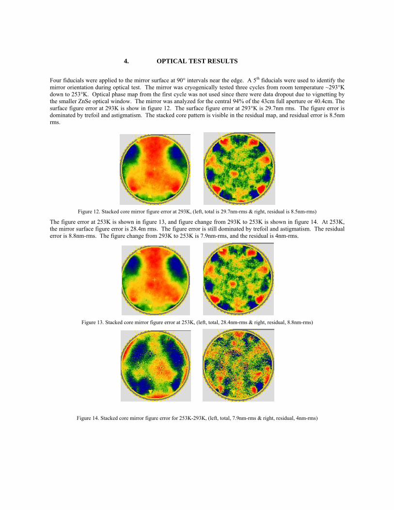
4. OPTICAL TEST RESULTS
Four fiducials were applied to the mirror surface at 90° intervals near the edge. A 5th fiducials were used to identify the mirror orientation during optical test. The mirror was cryogenically tested three cycles from room temperature ~293°K down to 253°K. Optical phase map from the first cycle was not used since there were data dropout due to vignetting by the smaller ZnSe optical window. The mirror was analyzed for the central 94% of the 43cm full aperture or 40.4cm. The surface figure error at 293K is show in figure 12. The surface figure error at 293°K is 29.7nm rms. The figure error is dominated by trefoil and astigmatism. The stacked core pattern is visible in the residual map, and residual error is 8.5nm rms.
Figure 12. Stacked core mirror figure error at 293K, (left, total is 29.7nm-rms & right, residual is 8.5nm-rms)
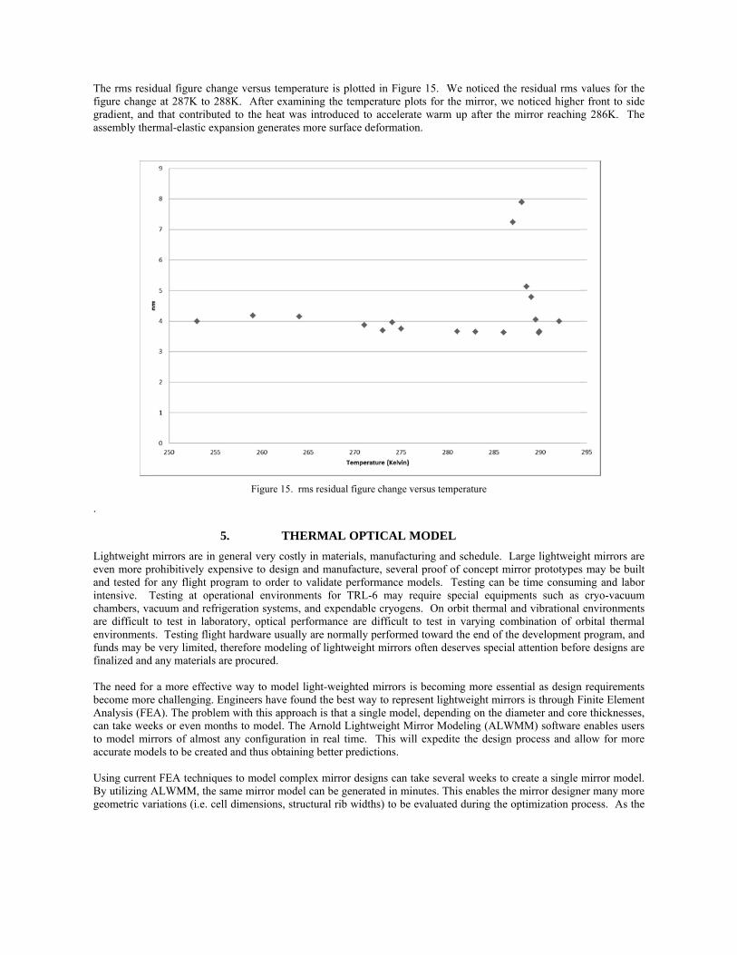
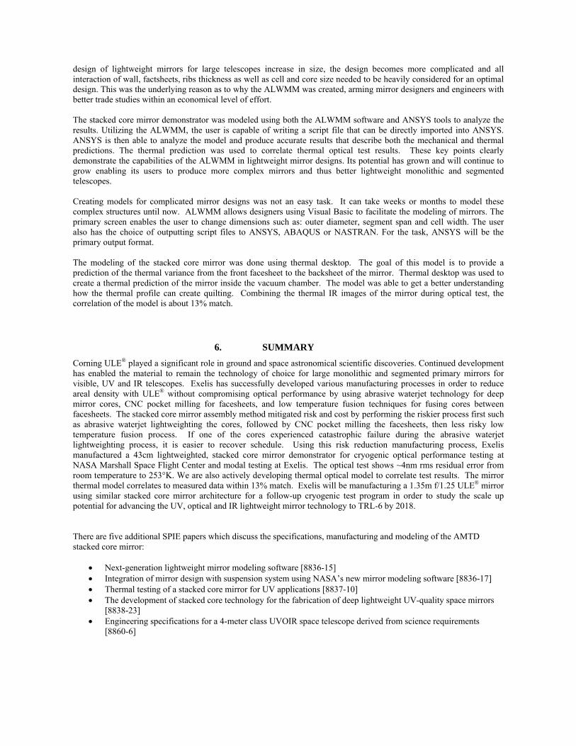
The figure error at 253K is shown in figure 13, and figure change from 293K to 253K is shown in figure 14. At 253K, the mirror surface figure error is 28.4m rms. The figure error is still dominated by trefoil and astigmatism. The residual error is 8.8nm-rms. The figure change from 293K to 253K is 7.9nm-rms, and the residual is 4nm-rms.
Figure 13. Stacked core mirror figure error at 253K, (left, total, 28.4nm-rms & right, residual, 8.8nm-rms)
Figure 14. Stacked core mirror figure error for 253K-293K, (left, total, 7.9nm-rms & right, residual, 4nm-rms)
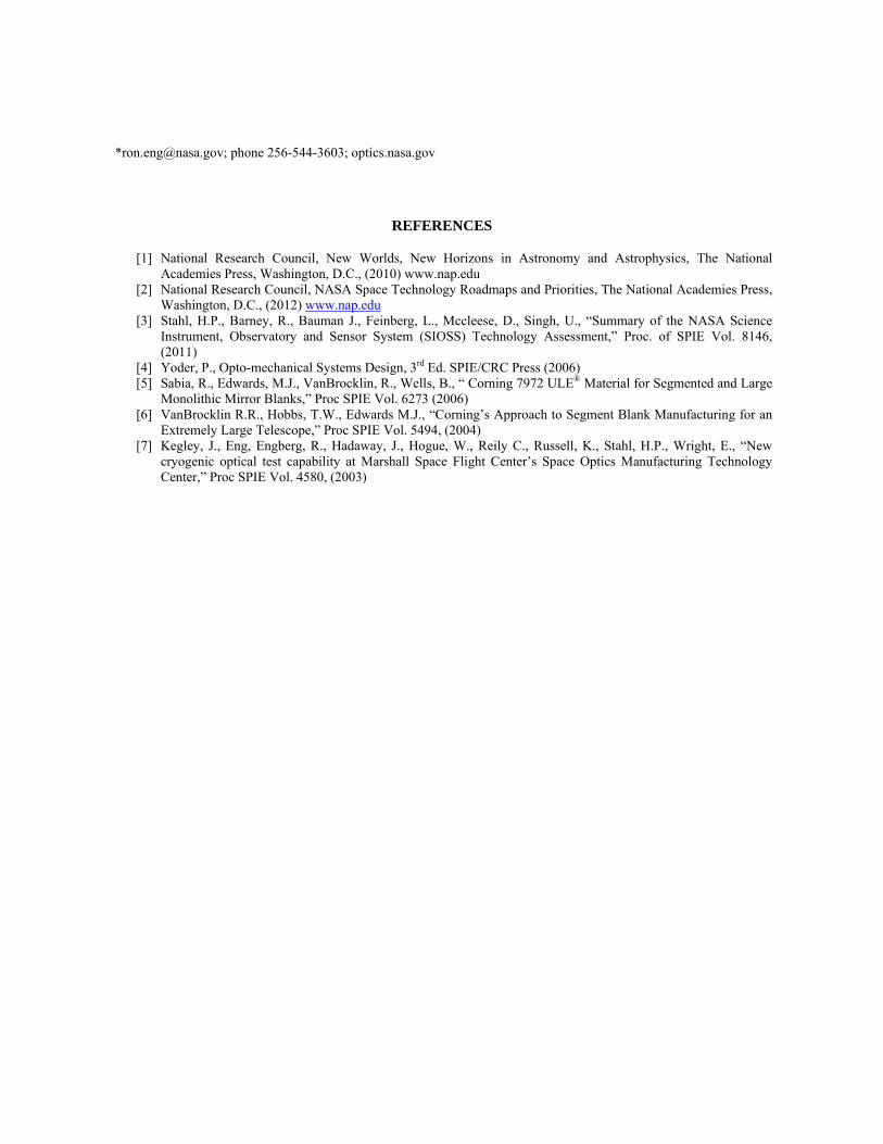
The rms residfigure changegradient, andassembly ther
.
Lightweight meven more prand tested fointensive. Tchambers, vaare difficult environmentsfunds may befinalized and The need for become moreAnalysis (FEcan take weekto model miraccurate mod Using currentBy utilizing Ageometric var
dual figure che at 287K to 2
d that contriburmal-elastic ex
mirrors are inrohibitively ex
or any flight pTesting at opacuum and refto test in labs. Testing flige very limitedany materials
a more effece challenging. A). The problks or even morrors of almosdels to be creat
t FEA techniqALWMM, theriations (i.e. c
hange versus t288K. After uted to the hexpansion gene
Figure
5.
n general veryxpensive to dprogram to orerational env
frigeration sysboratory, opticght hardware u, therefore mos are procured
ctive way to mEngineers ha
lem with this onths to modest any configuted and thus o
ques to modele same mirror cell dimension
temperature iexamining th
eat was introderates more su
e 15. rms residu
THERMA
y costly in matesign and mader to validat
vironments fostems, and expcal performanusually are noodeling of ligh
d.
model light-weave found the approach is thel. The Arnolduration in reaobtaining bette
l complex mirmodel can be
ns, structural r
s plotted in Fhe temperatureduced to accelurface deform
ual figure chan
AL OPTICA
terials, manufanufacture, sevte performancor TRL-6 mapendable cryonce are difficuormally perforhtweight mirr
eighted mirrobest way to rehat a single md Lightweight
al time. This er predictions.
rror designs cae generated inrib widths) to
Figure 15. Wee plots for thelerate warm u
mation.
ge versus temp
AL MODEL
facturing and veral proof ofce models. Teay require speogens. On orbult to test in rmed toward trors often dese
ors is becominepresent lightw
model, dependit Mirror Modwill expedite
.
an take severan minutes. Thi
be evaluated
e noticed the e mirror, we nup after the m
erature
schedule. Laf concept mirresting can beecial equipmebit thermal anvarying com
the end of theerves special a
ng more essenweight mirroring on the dia
deling (ALWMe the design p
al weeks to crs enables the during the op
residual rms noticed highe
mirror reachin
arge lightweigror prototypes time consuments such as
nd vibrational mbination of o
developmentattention befo
ntial as designrs is through Fameter and corMM) softwareprocess and al
reate a single mirror design
ptimization pr
values for ther front to side
ng 286K. The
ght mirrors ares may be buil
ming and laborcryo-vacuumenvironments
orbital thermat program, andore designs are
n requirementsFinite Elemenre thicknesses
e enables usersllow for more
mirror modelner many morerocess. As the
e e e
e lt r
m s
al d e
s nt s, s e
l. e e
design of lightweight mirrors for large telescopes increase in size, the design becomes more complicated and all interaction of wall, factsheets, ribs thickness as well as cell and core size needed to be heavily considered for an optimal design. This was the underlying reason as to why the ALWMM was created, arming mirror designers and engineers with better trade studies within an economical level of effort. The stacked core mirror demonstrator was modeled using both the ALWMM software and ANSYS tools to analyze the results. Utilizing the ALWMM, the user is capable of writing a script file that can be directly imported into ANSYS. ANSYS is then able to analyze the model and produce accurate results that describe both the mechanical and thermal predictions. The thermal prediction was used to correlate thermal optical test results. These key points clearly demonstrate the capabilities of the ALWMM in lightweight mirror designs. Its potential has grown and will continue to grow enabling its users to produce more complex mirrors and thus better lightweight monolithic and segmented telescopes. Creating models for complicated mirror designs was not an easy task. It can take weeks or months to model these complex structures until now. ALWMM allows designers using Visual Basic to facilitate the modeling of mirrors. The primary screen enables the user to change dimensions such as: outer diameter, segment span and cell width. The user also has the choice of outputting script files to ANSYS, ABAQUS or NASTRAN. For the task, ANSYS will be the primary output format.
The modeling of the stacked core mirror was done using thermal desktop. The goal of this model is to provide a prediction of the thermal variance from the front facesheet to the backsheet of the mirror. Thermal desktop was used to create a thermal prediction of the mirror inside the vacuum chamber. The model was able to get a better understanding how the thermal profile can create quilting. Combining the thermal IR images of the mirror during optical test, the correlation of the model is about 13% match.
6. SUMMARY
Corning ULE® played a significant role in ground and space astronomical scientific discoveries. Continued development has enabled the material to remain the technology of choice for large monolithic and segmented primary mirrors for visible, UV and IR telescopes. Exelis has successfully developed various manufacturing processes in order to reduce areal density with ULE® without compromising optical performance by using abrasive waterjet technology for deep mirror cores, CNC pocket milling for facesheets, and low temperature fusion techniques for fusing cores between facesheets. The stacked core mirror assembly method mitigated risk and cost by performing the riskier process first such as abrasive waterjet lightweighting the cores, followed by CNC pocket milling the facesheets, then less risky low temperature fusion process. If one of the cores experienced catastrophic failure during the abrasive waterjet lightweighting process, it is easier to recover schedule. Using this risk reduction manufacturing process, Exelis manufactured a 43cm lightweighted, stacked core mirror demonstrator for cryogenic optical performance testing at NASA Marshall Space Flight Center and modal testing at Exelis. The optical test shows ~4nm rms residual error from room temperature to 253°K. We are also actively developing thermal optical model to correlate test results. The mirror thermal model correlates to measured data within 13% match. Exelis will be manufacturing a 1.35m f/1.25 ULE® mirror using similar stacked core mirror architecture for a follow-up cryogenic test program in order to study the scale up potential for advancing the UV, optical and IR lightweight mirror technology to TRL-6 by 2018. There are five additional SPIE papers which discuss the specifications, manufacturing and modeling of the AMTD stacked core mirror:
Next-generation lightweight mirror modeling software [8836-15] Integration of mirror design with suspension system using NASA’s new mirror modeling software [8836-17] Thermal testing of a stacked core mirror for UV applications [8837-10] The development of stacked core technology for the fabrication of deep lightweight UV-quality space mirrors
[8838-23] Engineering specifications for a 4-meter class UVOIR space telescope derived from science requirements
[8860-6]
*[email protected]; phone 256-544-3603; optics.nasa.gov
REFERENCES
[1] National Research Council, New Worlds, New Horizons in Astronomy and Astrophysics, The National Academies Press, Washington, D.C., (2010) www.nap.edu
[2] National Research Council, NASA Space Technology Roadmaps and Priorities, The National Academies Press, Washington, D.C., (2012) www.nap.edu
[3] Stahl, H.P., Barney, R., Bauman J., Feinberg, L., Mccleese, D., Singh, U., “Summary of the NASA Science Instrument, Observatory and Sensor System (SIOSS) Technology Assessment,” Proc. of SPIE Vol. 8146, (2011)
[4] Yoder, P., Opto-mechanical Systems Design, 3rd Ed. SPIE/CRC Press (2006) [5] Sabia, R., Edwards, M.J., VanBrocklin, R., Wells, B., “ Corning 7972 ULE® Material for Segmented and Large
Monolithic Mirror Blanks,” Proc SPIE Vol. 6273 (2006) [6] VanBrocklin R.R., Hobbs, T.W., Edwards M.J., “Corning’s Approach to Segment Blank Manufacturing for an
Extremely Large Telescope,” Proc SPIE Vol. 5494, (2004) [7] Kegley, J., Eng, Engberg, R., Hadaway, J., Hogue, W., Reily C., Russell, K., Stahl, H.P., Wright, E., “New
cryogenic optical test capability at Marshall Space Flight Center’s Space Optics Manufacturing Technology Center,” Proc SPIE Vol. 4580, (2003)