crust formation in a (ferro)silicon furnace · crust formation in a (ferro)silicon furnace proposed...
TRANSCRIPT
Crust Formation in a (Ferro)Silicon Furnace
Proposed by: Dr S.A. Halvorsen, Elkem a/s Research, Norway,Report by: B.W. van de Fliert and LA. Frigaard,
Discussions by: SH, GLS, GR, JL, AN, JC, AL, CP, AF, CB.
AbstractElkem Research brought two problems concerning the (ferro)silicon process in anelectric furnace to the 27th ESGl.
The first problem concerned suggestions for and discussionof, improvements to anexisting unidimensional model of the silicon process. The unidimensional model wasdeveloped to describe dynamic aspects of the thermo-chemical processes occurringwithin the furnace. A major area for improvement in the model is in providing amore accurate description of the hearth region of the furnace.
The second problem concerned the proposal of mathematical models to describemechanisms for the formation of a hard crust at the furnace top. Crust formationappears to be dominated by SiO-condensation, due to the reaction:
2 SiO -+ Si02 + Si,
which occurs near the top of the furnace for sufficiently low temperatures.
1 Introduction.
At Elkem a/5, ferrosilicon is produced in large three-phase electric furnaces. A chargeconsisting of quartz (Si02), coal (C) and iron ore is supplied to the top of the furnace.The product, ferrosilicon, is formed at high temperatures (~ 2300K) and is tapped at thebottom of the furnace. The furnace can be pictured as a large vessel containing one ormore vertically oriented cylindrical electrodes. The furnace is then conceptually dividedinto "hearth" regions under the electrodes, where it is very hot, and "shaft" regionsalongside the electrodes, where it is cooler; see Fig. 1. The charge of raw materialsis at approximately room temperature when supplied to the top of the furnace and is"forced" into the furnace by stoking. The stoking takes place after a certain amount ofSiO and CO gases has escaped from the top of the furnace, with each stoking cycle takingapproximately one hour.
In the hearth of the furnace, during each stoking cycle, a gas filled cavity is formedaround the tip of each electrode. During operation the size of the cavity increases asthe charge materials are consumed on the sides and at the bottom of the cavity. Thiscontinues until either the layer of charge material at the top of the cavity breaks downor the shaft material is stoked down into the hearth and new materials are added at thetop, thus starting a new stoking cycle.
1
The overall process is strongly endothermic (hence the large electrodes) and is dom-inated by the silicon reactions. For this reason, one can concentrate largely on theproduction of pure silicon, ignoring the iron. The main components in the silicon processare: C, SiC and SiOz (solids); Si and SiOz (liquids); SiO and CO (gases). An additionalcomponent is a SiO "condensate", denoted by "SiO", which consists of a mixture of Siand SiOz. The melting temperatures of "SiO", Si and SiOz are approximately 1700Kand the temperatures in the furnace are in the ranges of 300 - 2200K in the shaft and2200 - 2400K in the hearth. The two dominant reactions that take place in the hearthof the furnace are:
.siO + SiC -4 2 Si + CO,
SiOz + Si -4 2 SiO.
(1)(2)
The first of these reactions produces Si, which can be tapped. The second reactionconsumes some of this Si in producing SiO. In the shaft region two reactions dominate:
2 SiO -4 sio, + Si (= 2 "SiO"),
SiO + 2 C -4 SiC + CO.(3)(4)
The production of SiO in the hearth and its recovery in the shaft are the essential steps inthe process. The hearth of the furnace must be in a state where silicon can be produced.This gives conditions on the temperatures and a lower bound for the SiO-pressure in thehearth. The gas exiting the top of the furnace also contains CO, which has been producedin the hearth via (1). However, if the gas exiting the top of the furnace contains a highcontent of SiO, then this means that the rate of silicon recovery at the bottom of thefurnace will be low. Reactions (3) and (4) govern the recovery of SiO. Reaction (3)involves the condensation of gaseous SiO, whilst through (4) a certain amount of SiOreacts with carbon present in the charge. A by-product of the process is silicon carbide,SiC, a hard porous solid material which is deposited both at the bottom and on thewalls of the hearth, whenever there is too much SiC to be consumed in reaction (1). Itis favourable to have all the carbon used in the shaft of the furnace, but conversely onedoes not want too much SiC to enter the hearth. This gives some bounds on the contentof carbon in the charge.
Furthermore, there is the formation of a hard crust at the walls of the furnace inthe upper part of the furnace. The crust consists mainly of SiOz (which can occur indifferent structures, i.e. crystals), but also carbon, silicon and silicon carbide are found inthe crust. After some months or years of operation the hard layer of SiC in the hearth,and/or the crust, may get too thick for the furnace to function well and it then needs tobe emptied, with a consequent productivity penalty.
2 Current process models and proposed improvements.
Elkem a/s have had an ongoing research programme into various aspects of the ferrosili-con process since the 1950's. Initially the mathematical aspects of this programme were
2
confined to the development of a stochiometric model, which has yielded much informa-tion about the basic operational requirements of the process. However, to reflect theessentially dynamic nature of the process (e.g. the variations throughout the stokingcycles), starting in 1984, Dr Halvorsen has been developing a unidimensional dynamicmodel of the (pure) silicon process.
The essential elements of the current model are as follows. Firstly, there is a setof sub-models giving the kinetic rate laws for each chemical reaction. The shaft regionof the furnace is then modelled through a set of coupled partial differential equations,describing mass conservation for each species, together with a one-dimensional heat con-servation equation. Solid phase velocity is determined by assuming that all gases, liquidsand "SiO" occupy only the interstitial spaces between granules of solid charge, and thenby assuming that any further voids created (e.g. by reaction and/or melting) are :filledimmediately by the solid flow. The liquid phase mass flux is computed backwards from anequation for the total conservation of the liquid phase, and the gas velocity is computedby including the additional assumption that the sum of the partial gas pressures is 1 atm.The shaft equations are coupled through boundary conditions to a set of ordinary differ-ential equations describing the hearth region of the furnace. These ordinary differentialequations describe species/mass conservation and heat conservation.
This unidimensional model has been solved numerically for a range of process condi-tions, both when the furnace is stoked continuously and in cycles. Although very useful,it has been recognised by Elkem that there are still a number of deficiencies in the model.Possible areas for improvement of the unidimensional model that have been proposedinclude the following.
• Shaft region:
- The electrodes also provide power to the shaft region.
- Heat losses through the furnace walls in the shaft region can be included.
- Improve the description for the flow of solids and liquids.
The volume fraction occupied by the solids is not constant.
The carbon electrode is, as well as an energy source, a supplier of carbon tothe process.
• Hearth region:
- The finite size of the hearth region should be included, perhaps by a distributedhearth region model consisting of one or more zones/computation cells of finitevolume.
The reactions taking place in the hearth and the effects that these reactionshave on the hearth volume need to be reexamined.
Include heat losses by conduction through the bottom and walls of the hearthregion.
The position of the electrodes, which is adjusted by the furnace control system,can be included in this description.
3
Include continuous or limited tapping periods of the silicon.
Slagging may occur, when viscous Si02 and solid SiC are tapped along withthe silicon.
One major aim of Elkem a/s, in bringing this problem to the study group, was to discussways of incorporating some of the above effects into the unidimensional model. Theforemost consideration in doing this however, was that improvements suggested shouldbe able to be incorporated reasonably simply into the current computational framework.During the week many of the above problems were discussed, with various participantsat the study group making practical suggestions, mostly in keeping with the spirit ofthe current model. The suggestions focussed mainly on an improved description of thefurnace hearth region. Below are outlined some of these suggested improvements.
1. A single zone finite volume hearth model was recommended as an initial improve-ment. In this model the hearth is described by variables for the volume, the floorarea, the wall area and the height below the electrode tip. There were some argu-ments for considering a multi-zone model, with different phases and species presentin each zone, but the inter-zone reaction/transfer rates then become difficult tomodel.
2. Currently the mass flux into the hearth region is partially determined by a boundarycondition on the solid phase velocity, between the hearth and shaft regions. Theinfluence of the finite size of the hearth region can be included by a smooth "cut-off"of the solid phase velocity when a certain critical volume of solid is exceeded in thehearth. This critical volume can be determined approximately from the maximumamount of new charge material that can be added at the top of the furnace afterstoking in each stoking cycle.
3. If there is too much SiC in the hearth region, then reaction (1) cannot consumeit fast enough, and the surplus becomes deposited on the sides and walls of thehearth. It was suggested that this effect be incorporated via an additional "reaction"(postulated to take place when the total mass of SiC in the hearth exceeds a certaincritical mass), which converts normal "active" SiC to another species of "inactive"SiC, only present in the hearth. The reaction rate and critical mass of active SiCneed to be determined/modelled.
4. Of the inactive SiC formed in the hearth, an amount proportional to the hearth wallarea is deposited on the walls; the remainder is deposited on the floor of the hearth.Given a known hearth floor area, the height of the "layer" of inactive SiC depositedon the bottom of the hearth can be computed, and then this can be continuouslysubtracted from the hearth volume.
5. Also for given hearth floor area and mass of silicon in the hearth, the height of thepool/layer of liquid Si can be computed, including in the computation any Si thathas been tapped.
4
6. The position of the electrode is usually adjusted to maintain a constant powerinput, which corresponds (approximately) to maintaining a constant distance fromthe electrode tip to the top of the layer of liquid Si on the base of the hearth.
7. In the current model the reaction rate for (2) is not assumed to depend upon theconcentration of Si. This is because normally there is a plentiful supply of Si inthe hearth, with which the Si02 can react. It was suggested that the reaction (2)would be influenced by the amount of liquid Si in the hearth region, when thisamount is small, and that this effect should also be incorporated. This highlightedthe problem that, if reaction (2) is "cut-off" for a low mass of Si, then there is nomechanism in the current model for the production of SiO gas, which is potentiallycatastrophic for the process. Thus, it would then be necessary to reintroduce intothe model the reaction:
2 Si02 + SiC ~ 3 SiO + CO,
which is known to take place in the hearth, but is not dominant usually.
8. It was suggested that heat losses, by conduction, through the bottom and wallsof the hearth region be included computationally by two separate, fairly coarse,one-dimensional finite-volume heat transfer models. The thickness of inactive SiCon the bottom of the hearth is usually much greater than that on the sides of thehearth. Thus, the two models should correspond to the sideways and downwardsheat losses respectively. A number of different process response time scales havealready been identified from the existing unidimensional model. It was suggestedthat a variable thickness of volume elements be used in each of these two models,and that the different element thicknesses used should correspond to the distanceof propagation of a thermal transient on each of the different time scales.
3 Crust formation close to the furnace top.
The second problem area of interest to Elkem a/ s, in coming to the study group, concernedthe proposal of mathematical models to describe mechanisms for the formation of a hardcrust near the top of the furnace. Reactions (3) and (4) are both exothermic and cantake place at the lower temperatures that are found in the furnace shaft. Close to thetop of the furnace a hard crust of porous material may be formed, consisting of Si02, Cand SiC. It is believed that the crust formation is dominated by the SiO-condensation,
2 SiO ~ Si02 + Si,
which (depending on the temperature), can produce a hard glass-like solid. In extremecases, and over a period of months or years, this crust growth can result in the furnacebeing shut down.
The solid charge is fed in at the top of the furnace at approximately room temperatureand with a constant void fraction. Lower in the shaft, the solid temperatures increasesto nearly the hearth temperature. It is postulated that crust formation results from
5
condensation on the (cold) wall. The main driving force for the condensation is thetemperature difference between the hot gas coming from the hearth (~ 2300K) and thesolid material. Condensation takes place if the temperature drops below a certain criticaltemperature (T < T* ~ 2000K). Since the solid material is relatively cold, it is assumedthat the condensation takes place at the solid particles, Le. the condensation is a surfacereaction.
The above suggested mechanism for crust formation is supported by the evidence thatthe crust is observed only to form at the furnace walls and not at the electrode, wherethe temperature will typically be too high for significant condensation to occur. As wellas the vertical temperature gradient in the shaft, there will be a temperature gradientacross the shaft due to heat inflow from the electrode and outflow through the furnacewalls. The condensation reaction will take place throughout the shaft, the voids in theincoming material being filled with condensate. However, nearer the electrode and in thebulk of the shaft region the condensate will be forced down into the hearth, together withthe charge. Only near the furnace walls (where the lower temperatures should guaranteea higher condensation rate), is the condensate likely to stick, cool and form a hard crust.
In the following analysis the growth rate of the crust is therefore modelled as beingproportional to the rate of condensation and to the surface area of the wall exposedto reaction at which the solid material may stick. The liquid and solid phases will betreated the same, so that melting of the different species need not be considered. In thefurnace shaft we assume a downwards solid/liquid flux opposed by an upwards gas flux.Two models for crust formation are considered. In the first model it is proposed thatthe crust is formed slowly, and due to SiO-condensation alone. In the second model theexothermic reaction (4) is also taken into account and furthermore, the process is studiedon the stoking time scale.
The following notation will be used:t = time, Z = vertical position in shaft, x, y = horizontal position,Ts, Tg = local absolute temperature of solid, gas component (K),CS, cg = local concentration of solid, gas (mol / m3),
Vs,Vg = velocity of solid, gas (m/s),R = reaction rate (mol/m3s),
and we define the following constants and coefficients:T* = equilibrium (critical) temperature,Te, Tw = temperatures of electrode and wall,a,(3",fJ = (reaction) constants,D = diffusion coefficient gas,"'i = P;~i' k; = thermal conductivity, Pi = density, Ci = specific heat, i = g, s.
3.1 Crust formation due to SiO-condensation on a long time scale.
A first model for the crust formation simplifies the process to a SiO-condensation: 2 SiO -+
Si02 + Si at sufficiently low temperatures. Restricting the domain of interest to the shaft
6
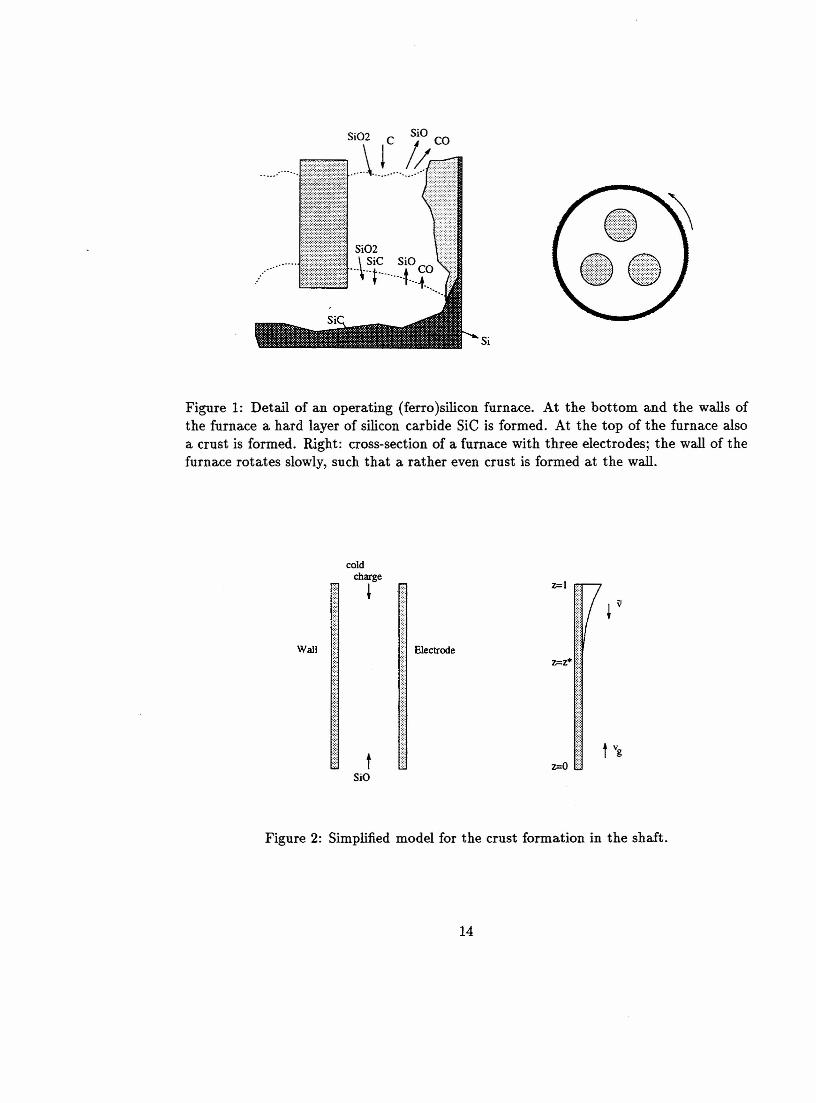
of the furnace, a given supply of SiO gas is coming from the hearth, and similarly a givensupply of charge is fed to the top of the idealised reactor. See Fig. 2.
Since only one reaction is used, only the concentration cg of the SiO gas needs to beconsidered. Its change is determined by the diffusion and the reaction rate:
(5)
For this condensation two gas molecules react to form solid (or liquid) if the temperatureat the surface of the solid is below the critical condensation temperature. Therefore thereaction rate is modelled by:
R = ~c;(T* - Ts)+, (6)
with reaction constant ~. The temperatures Tg and T; of gas and solid are given by heatconduction equations:
pgCg (O~g +V.(.QgTg») = V.(kgVTg)+a1R-H,
PsCs (O~s + V. C1tsTs») = V· (ksVTs) + azR + H.
(7)
(8)
The terms aiR give the amount of heat that is released from the exothermic reaction,going into the gas or the solid respectively. We will assume that the heat released fromthe reaction will go into the solid material that is formed by the condensation reaction.This means that a1 = O.
The term H models the heat transfer from the gas to the solid, depending on thetemperature difference (Tg - Ta). This will be modelled with a linear relation:
(9)
for a given constant f3. If f3 is very large, then the heat transfer between solid and gas isalmost immediate and the solid and gas will have approximately the same temperatureat each height in the shaft. If f3 is small, the temperature of the gas that escapes at thetop of the furnace will be almost the same as the temperature at the bottom.
Boundary conditions are given by:- at the crust boundary h (heat transfer and no flux conditions):
et, ( er,on = "'Iwg Tg - Tw), on = "'Iws(Tg - Tw),
oCg _ 0on - ,- at the electrode (heat transfer and no flux conditions):
(10)
(11)
er, ( et,on = "'leg Tg - Te), an = "'Ies(Ts - Te),
oCg _ 0on - ,
(12)
(13)
7
- at the bottom and top of the shaft:
Tg = To, cg = Co, at z = 0, T; = TL, at z = L (14)
The formation of the crust is modelled by:
8h8t =, R, at the crust boundary h, (15)
which gives the growth of the thickness of the crust layer, proportional to the reactionrate and the surface area of the wall.
To close the system we need initial conditions at t = 0 and an equation for thevelocities. A possible choice is describing the flow through a porous medium; however wewill use constant velocities for simplicity.
An important model assumption is the time scale on which the process of the crustformation takes place. In this first model the time scale for the crust formation is assumedto be long, such that after scaling, the only time component is in the dynamical equationfor the growth of the crust and all other processes are quasi-static.
One-dimensional model for a thin crust.
We will first concentrate on the one-dimensional model, in the case of a thin crust (whichdoes not influence the flow through the shaft). For a one-dimensional model we needsimilar boundaries on each side of the shaft. Both boundaries (wall or crust and electrode)are assumed to be good insulators.
A scaling is done for a thin crust and for a long time period. Non-dimensionalisationand scaling (with e the ratio of crust thickness over shaft width, c ~ 1) are as follows.With at z = 0 a given gas temperature To, gas concentration Co, gas velocity Vo, and withL the length of shaft, define the non-dimensional variables:
z - tvo - h _ Vg Vs _ cgZ= L' t=T' h=-, Vg =-, Vs =-, cg =-,
cL Vo Vo Co- Tg - Ts t: _T* - RL
H=HL
Tg=-, Ts=-, R=--,To To - To' VOCo voToPgcg
The temperature at z = L is scaled to TL/To which we will set to zero. The dimensionlessparameters are:
- f3Lf3=--,
VOPgCgt = ,co, 6 = 6coToL,
L VoKo_ t
Ki = --,Lvo- DD=-.
Lvo
To leading order in e and on a long time scale (such that all processes are stationaryexcept for the crust growth), ignoring small terms related to diffusion and conduction,we find the following set of equations:
8(vgTg) -H, (16)8z
Pscs 8(vsTs) aR+H, (17)pgCg 8z
8
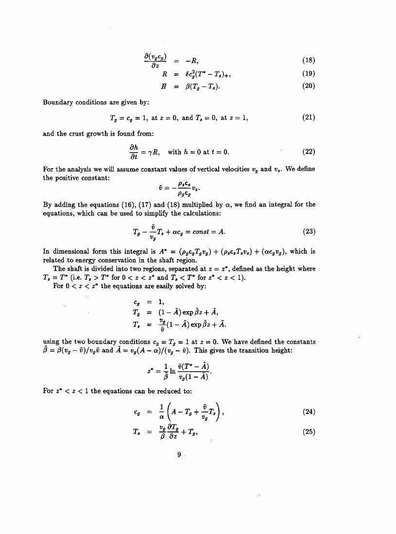
a(VgCg) = -R,azR = c5c;(T* - T,,)+,
H = f3(Tg - T,,).
(18)
(19)
(20)
Boundary conditions are given by:
Tg = cg = 1, at z = 0, and T" = 0, at z = 1, (21)
and the crust growth is found from:
ah. at = "Y R, with h = 0 at t = o. (22)
For the analysis we will assume constant values of vertical velocities Vg and V". We definethe positive constant:
_ p"c"V= ---VS'
pgCgBy adding the equations (16), (17) and (18) multiplied by a, we find an integral for theequations, which can be used to simplify the calculations:
VTg - -Ts + aCg = const = A.
Vg(23)
In dimensional form this integral is A* = (pgcgTgvg) + (p"c"T"vs) + (acgvg), which isrelated to energy conservation in the shaft region.
The shaft is divided into two regions, separated at z = z", defined as the height whereT" = T* (i.e. T" > T* for 0 < z < z* and T" < T* for z· < z < 1).
For 0 < z < z" the equations are easily solved by:
Cg 1,Tg = (1- .A)exp,Bz +.A,
V - - -T" = 3(1- A)expf3z + A.V
using the two boundary conditions cg = Tg = 1 at z = O.We have defined the constants .,B = f3(Vg - v)/vgv and A = viA - a)/( Vg - v). This gives the transition height:
z* = lln v(T* - ~) .f3 viI - A)
For z" < z < 1 the equations can be reduced to:
(24)
(25)
9

and the following o.d.e. for the temperature of the gas:
(26)
We will look at the solution in more detail for the case of small parameter 6, which cor-responds to the physical situation that only a negligible amount of gas is taken up by thecondensation (which seems to be in agreement with numerical experiments) and/or thatthe ratio of surface area of the solid particles over the total volume is small. Asymptoticexpansion in 6 gives in leading order that no reaction takes place, although the tem-perature drops below the critical temperature. Expand z", A, the crust thickness, gasconcentration and temperatures in series of 6. To leading order this is easily found togive:
1,vg( exp jjz - exp jj)
v - vgexp jjvexp jjz - Vg exp jj
v - Vg expjj
The integration constants are found from continuity of the temperatures at:
z~ = ~ln (T* v + (1- T*)eXpjj), with AO = a + (~- vg)exp!.{3 Vg V - Vgexp {3
The growth of the crust to leading order (with hO = 0) is then given by:
{
0, 0 S; z S; z'",
h1(z, t) = it (T* _ vg( ~xp jjz - e~ jj»), z* S; z S; 1.
V - Vg exp (3
The solution is found more accurately from the expansion to higher order in 6 and thecrust growth is then found similarly for z > zo + 6zi + 0(62).
(27)
Other simplifications of the model.
When looking at the asymptotic expansion for large parameter {3,which corresponds toa immediate heat transfer between gas and solid, it is found in leading order that the gasand solid in the lower part of the shaft will have constant temperatures Tg = T; = 1 andalso the gas concentration is constant, cg = 1. There will be a transition region given bya boundary layer around some value z", The inner solution in this transition layer mustbe matched with the outer solutions in the lower and the upper part of the shaft. It isnot clear what will determine the value of z" however and this might be interesting toinvestigate.
An other case that can be investigated further is the model for a thick crust, us-ing either a boundary layer approach or lubrication theory. The (non-dimensionalised)equations and boundary conditions are given by:
10
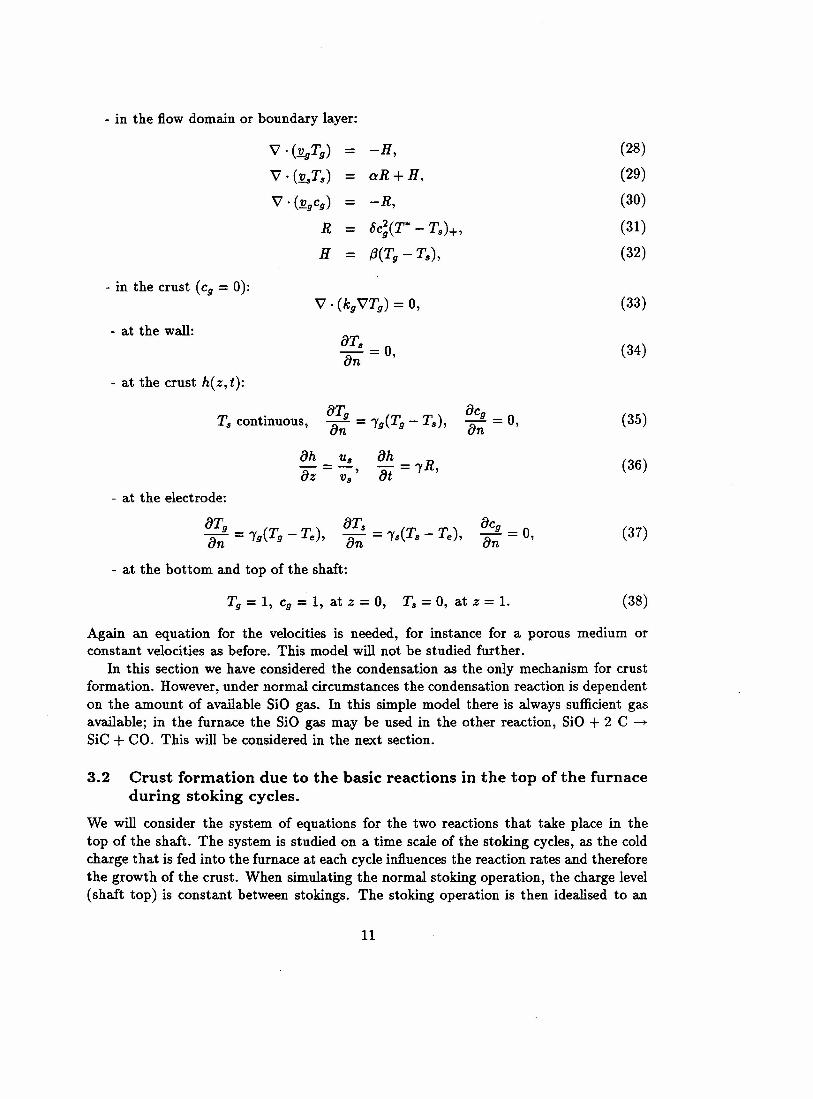
- in the flow domain or boundary layer:
v .(:!lgTg) = -H,V . (.!laTs) aR+H,V . (:!lgCg) -R,
R = oc;(T* - Ts)+,
H = f3(Tg - Ts),
(28)
(29)
(30)
(31)
(32)
- in the crust (cg = 0):V· (kgVTg) = 0, (33)
- at the wall:aTs = 0an ' (34)
- at the crust h(z, t):
et, ( )T; continuous, an = Ig Tg - Ts ,aCg _ 0an - , (35)
oh Us= ,az Vs(36)
- at the electrode:
er, ( )an = 19 Tg - Te ,aCg _ 0an - , (37)
- at the bottom and top of the shaft:
Tg = 1, cg = 1, at z = 0, T; = 0, at z = 1. (38)
Again an equation for the velocities is needed, for instance for a porous medium orconstant velocities as before. This model will not be studied further.
In this section we have considered the condensation as the only mechanism for crustformation. However,under normal circumstances the condensation reaction is dependenton the amount of available SiO gas. In this simple model there is always sufficient gasavailable; in the furnace the SiO gas may be used in the other reaction, SiO+ 2 C ~SiC + CO. This will be considered in the next section.
3.2 Crust formation due to the basic reactions in the top of the furnaceduring stoking cycles.
We will consider the system of equations for the two reactions that take place in thetop of the shaft. The system is studied on a time scale of the stoking cycles, as the coldcharge that is fed into the furnace at each cycleinfluencesthe reaction rates and thereforethe growth of the crust. When simulating the normal stoking operation, the charge level(shaft top) is constant between stokings. The stoking operation is then idealised to an
11
instantaneous time discrete event, when the remaining shaft material is pushed down andthe shaft is restored to its full height by adding the necessary amount of fresh charge mix.
We need to consider the temperature Tg of the gases SiO and CO and T; of the solidsand liquids Si02, Si, SiC, C. The gases move upwards with velocity Vg while the solids arenot pushed down during one stoking cycle (vs = 0). For simplicity we take Vg constantand assume that the crust is thin.
From the two reactions it follows that the model equations can be reduced to equationsfor the concentrations of the gas SiO and of the solid carbon C, which we will denote bycg and Cs. (The temperatures Tg and T; are still temperatures of the ensemble of gasesand solids in the shaft.)
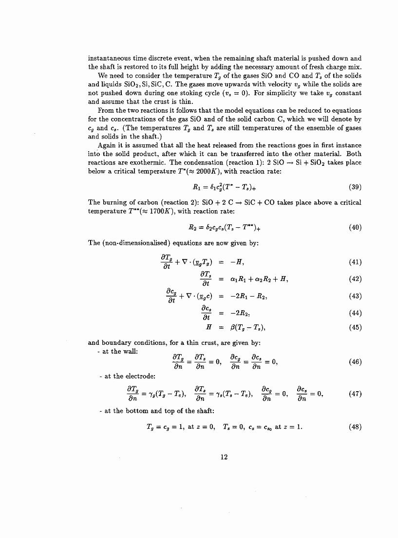
Again it is assumed that all the heat released from the reactions goes in first instanceinto the solid product, after which it can be transferred into the other material. Bothreactions are exothermic. The. condensation (reaction 1): 2 SiO ~ Si + Si02 takes placebelow a critical temperature T*( ~ 2000K), with reaction rate:
(39)
The burning of carbon (reaction 2): SiO + 2 C -+ SiC + CO takes place above a criticaltemperature T**( ~ 1700K), with reaction rate:
R2 = b2CgCs(Ts - T**)+ (40)
The (non-dimensionalised) equations are now given by:
or, ( ) -H, (41)ot + V'. 'l2.gTg ==er,
aIRI + a2R2 + H, (42)==otOCg ) -2RI - R2' (43)-+V'·(v C =ot -g
Be,-2R2' (44)=ot
H = f3(Tg - Ts), (45)
and boundary conditions, for a thin crust, are given by:- at the wall:
oTg == oTs == 0,on on
OCg = oCs == 0,on on
(46)
- at the electrode:
OCg _ 0on - , OCs = 0,
on(47)
- at the bottom and top of the shaft:
Tg = Cg = 1, at z = 0, T; = 0, Cs = Cso at z = 1. (48)
12
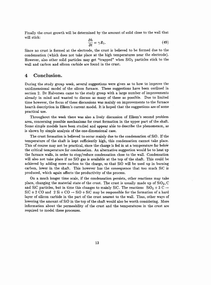
Finally the crust growth will be determined by the amount of solid close to the wall thatwill stick: oh- = 'YRl.otSince no crust is formed at the electrode, the crust is believed to be formed due to thecondensation (which does not take place at the high temperatures near the electrode).However, also other solid particles may get "trapped" when Si02 particles stick to thewall and carbon and silicon carbide are found in the crust.
(49)
4 Conclusion.
During the study group week, several suggestions were given as to how to improve theunidimensional model of the silicon furnace. These suggestions have been outlined insection 2. Dr Halvorsen came to the study group with a large number of improvementsalready in mind and wanted to discuss as many of these as possible. Due to limitedtime however, the focus of these discussions was mainly on improvements to the furnacehearth description in Elkem's current model. It is hoped that the suggestions are of somepractical use.
Throughout the week there was also a lively discussion of Elkem's second problemarea, concerning possible mechanisms for crust formation in the upper part of the shaft.Some simple models have been studied and appear able to describe the phenomenon, asis shown by simple analysis of the one-dimensional case.
The crust formation is believed to occur mainly due to the condensation of SiO. If thetemperature of the shaft is kept sufficiently high, this condensation cannot take place.This of Course may not be practical, since the charge is fed in at a temperature far belowthe critical temperature for condensation. An alternative suggestion would be to heat upthe furnace walls, in order to stop/reduce condensation close to the wall. Condensationwill also not take place if no SiO gas is available at the top of the shaft. This could beachieved by adding more carbon to the charge, so that SiO will be used up in burningcarbon, lower in the shaft. This however has the consequence that too much SiC isproduced, which again affects the productivity of the process.
On a much longer time scale, if the condensation persists, other reactions may takeplace, changing the material state of the crust. The crust is usually made up of Si02, Cand SiC particles, but in time this changes to mainly SiC. The reactions Si02 + 3 C -+
SiC + 2 CO and 2 Si + CO -+ SiO + SiC may be responsible for the formation of a hardlayer of silicon carbide in the part of the crust nearest to the wall. Thus, other ways oflowering the amount of SiO in the top of the shaft would also be worth considering. Moreinformation about the permeability of the crust and the temperatures in the crust arerequired to model these processes.
13
•\\••Si02
\SiC SiO
·····l········t ...~O........
Si
Figure 1: Detail of an operating (ferro)silicon furnace. At the bottom and the walls ofthe furnace a hard layer of silicon carbide SiC is formed. At the top of the furnace alsoa crust is formed. Right: cross-section of a furnace with three electrodes; the wall of thefurnace rotates slowly, such that a rather even crust is formed at the wall.
coldcharge
~
Wall 1.1:
I:· tSiO
••••\}
i~)[:::: Electrode
Figure 2: Simplified model for the crust formation in the shaft.
14