crumblebot assembly and usage - 4tronix4tronix.co.uk/crumble/crumblebot.pdf · - page 1 -...
TRANSCRIPT
- Page 1 -
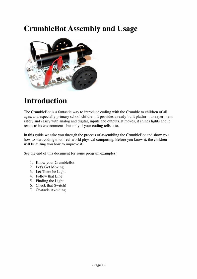
CrumbleBot Assembly and Usage
Introduction
The CrumbleBot is a fantastic way to introduce coding with the Crumble to children of all
ages, and especially primary school children. It provides a ready-built platform to experiment
safely and easily with analog and digital, inputs and outputs. It moves, it shines lights and it
reacts to its environment - but only if your coding tells it to.
In this guide we take you through the process of assembling the CrumbleBot and show you
how to start coding to do real-world physical computing. Before you know it, the children
will be telling you how to improve it!
See the end of this document for some program examples:
1. Know your CrumbleBot
2. Let's Get Moving
3. Let There be Light
4. Follow that Line!
5. Finding the Light
6. Check that Switch!
7. Obstacle Avoiding
- Page 2 -
Assembling CrumbleBot
Nothing could be simpler really, but let's break it down into a few easy steps
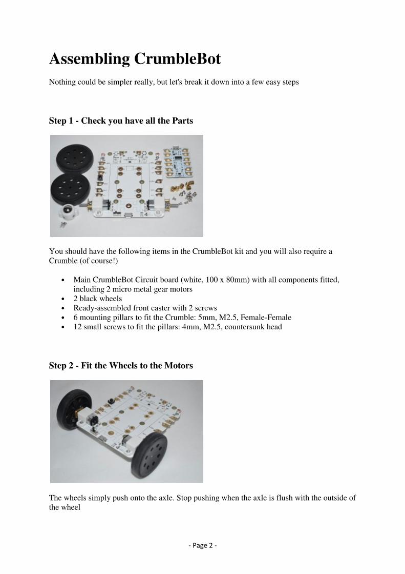
Step 1 - Check you have all the Parts
You should have the following items in the CrumbleBot kit and you will also require a
Crumble (of course!)
• Main CrumbleBot Circuit board (white, 100 x 80mm) with all components fitted,
including 2 micro metal gear motors
• 2 black wheels
• Ready-assembled front caster with 2 screws
• 6 mounting pillars to fit the Crumble: 5mm, M2.5, Female-Female
• 12 small screws to fit the pillars: 4mm, M2.5, countersunk head
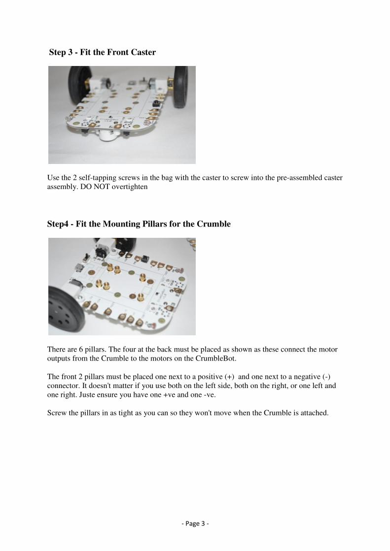
Step 2 - Fit the Wheels to the Motors
The wheels simply push onto the axle. Stop pushing when the axle is flush with the outside of
the wheel
- Page 3 -
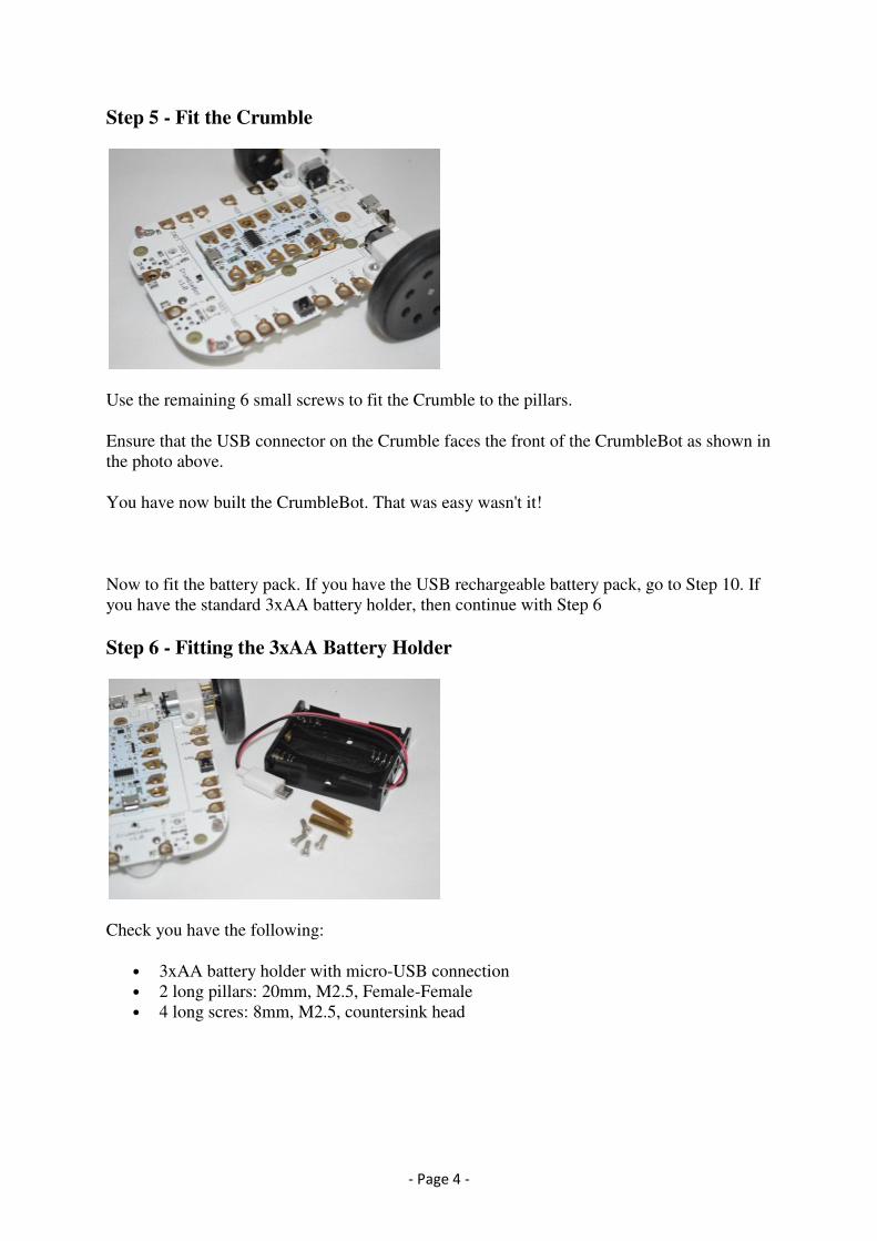
Step 3 - Fit the Front Caster
Use the 2 self-tapping screws in the bag with the caster to screw into the pre-assembled caster
assembly. DO NOT overtighten
Step4 - Fit the Mounting Pillars for the Crumble
There are 6 pillars. The four at the back must be placed as shown as these connect the motor
outputs from the Crumble to the motors on the CrumbleBot.
The front 2 pillars must be placed one next to a positive (+) and one next to a negative (-)
connector. It doesn't matter if you use both on the left side, both on the right, or one left and
one right. Juste ensure you have one +ve and one -ve.
Screw the pillars in as tight as you can so they won't move when the Crumble is attached.
- Page 4 -
Step 5 - Fit the Crumble
Use the remaining 6 small screws to fit the Crumble to the pillars.
Ensure that the USB connector on the Crumble faces the front of the CrumbleBot as shown in
the photo above.
You have now built the CrumbleBot. That was easy wasn't it!
Now to fit the battery pack. If you have the USB rechargeable battery pack, go to Step 10. If
you have the standard 3xAA battery holder, then continue with Step 6
Step 6 - Fitting the 3xAA Battery Holder
Check you have the following:
• 3xAA battery holder with micro-USB connection
• 2 long pillars: 20mm, M2.5, Female-Female
• 4 long scres: 8mm, M2.5, countersink head
- Page 5 -
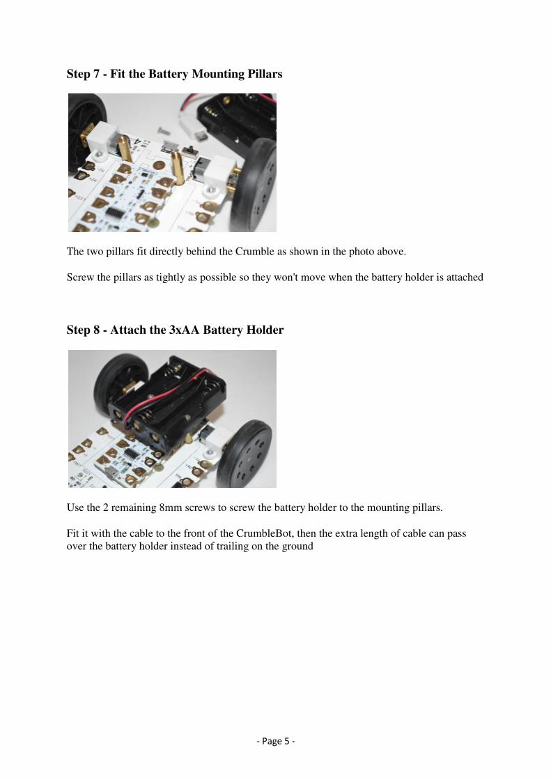
Step 7 - Fit the Battery Mounting Pillars
The two pillars fit directly behind the Crumble as shown in the photo above.
Screw the pillars as tightly as possible so they won't move when the battery holder is attached
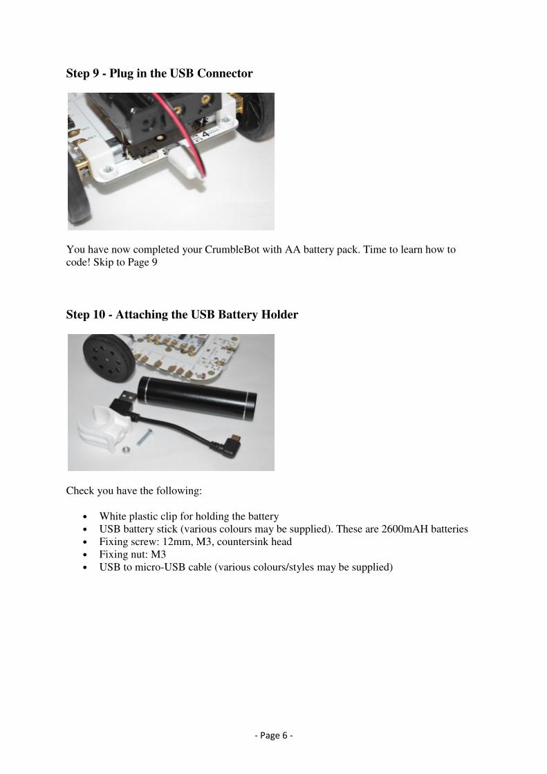
Step 8 - Attach the 3xAA Battery Holder
Use the 2 remaining 8mm screws to screw the battery holder to the mounting pillars.
Fit it with the cable to the front of the CrumbleBot, then the extra length of cable can pass
over the battery holder instead of trailing on the ground
- Page 6 -
Step 9 - Plug in the USB Connector
You have now completed your CrumbleBot with AA battery pack. Time to learn how to
code! Skip to Page 9
Step 10 - Attaching the USB Battery Holder
Check you have the following:
• White plastic clip for holding the battery
• USB battery stick (various colours may be supplied). These are 2600mAH batteries
• Fixing screw: 12mm, M3, countersink head
• Fixing nut: M3
• USB to micro-USB cable (various colours/styles may be supplied)

- Page 7 -
Step 11 - Attach the Mounting Clip
Pass the screw through the plastic pillar, through the CrumbleBot PCB and into the nut.
Tighten well
Twist the clip if necessary to make it point forwards
Step 12 - Fit the USB Battery Pack
Push the USB Battery Pack through the clip from the front. Do not attempt to clip it in from
above as it is very stiff.
- Page 8 -
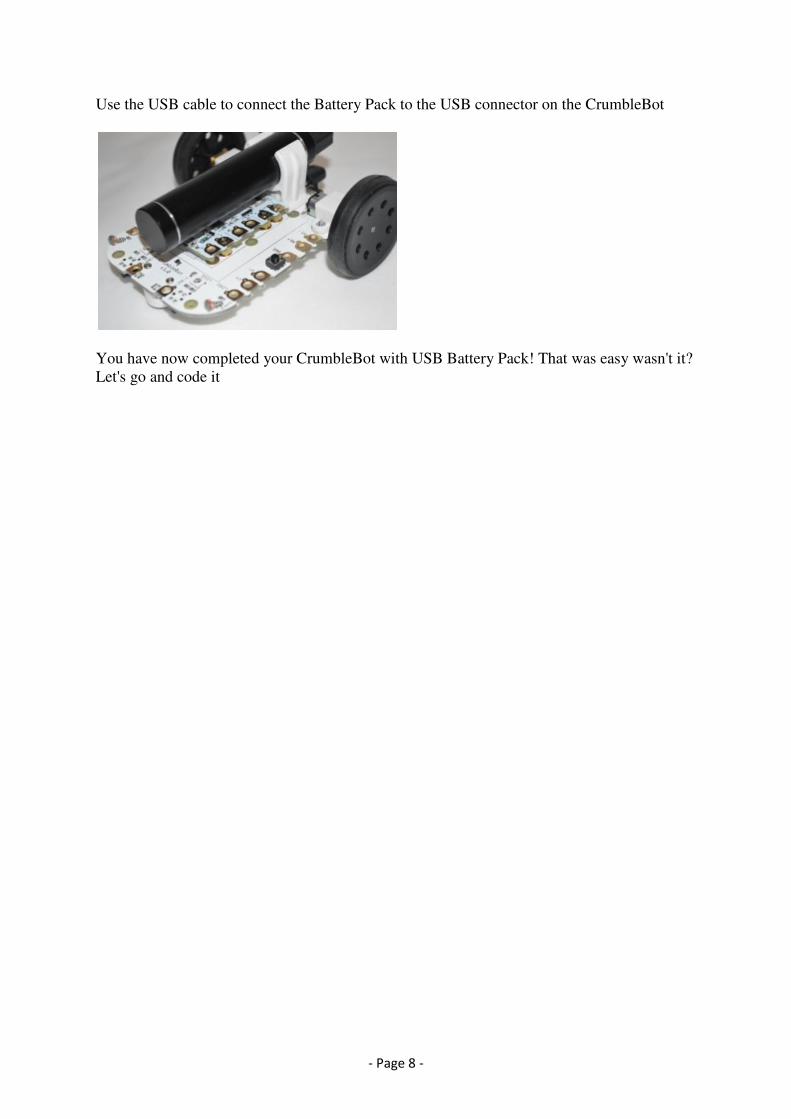
Use the USB cable to connect the Battery Pack to the USB connector on the CrumbleBot
You have now completed your CrumbleBot with USB Battery Pack! That was easy wasn't it?
Let's go and code it
- Page 9 -
Coding for your CrumbleBot
** Please note that only the motors are permanently connected. All other features require one
or more croc clips (included) to be connected from the Crumble to the Crumblebot. This
allows more features to be included than can be active at any one time.
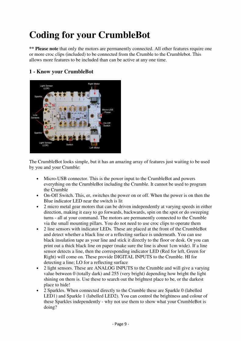
1 - Know your CrumbleBot
The CrumbleBot looks simple, but it has an amazing array of features just waiting to be used
by you and your Crumble:
• Micro-USB connector. This is the power input to the CrumbleBot and powers
everything on the CrumbleBot including the Crumble. It cannot be used to program
the Crumble
• On-Off Switch. This, er, switches the power on or off. When the power is on then the
Blue indicator LED near the switch is lit
• 2 micro metal gear motors that can be driven independently at varying speeds in either
direction, making it easy to go forwards, backwards, spin on the spot or do sweeping
turns - all at your command. The motors are permanently connected to the Crumble
via the small mounting pillars. You do not need to use croc clips to operate them
• 2 line sensors with indicator LEDs. These are placed at the front of the CrumbleBot
and detect whether a black line or a reflecting surface is underneath. You can use
black insulation tape as your line and stick it directly to the floor or desk. Or you can
print out a thick black line on paper (make sure the line is about 1cm wide). If a line
sensor detects a line, then the corresponding indicator LED (Red for left, Green for
Right) will come on. These provide DIGITAL INPUTS to the Crumble. HI for
detecting a line; LO for a reflecting surface
• 2 light sensors. These are ANALOG INPUTS to the Crumble and will give a varying
value between 0 (totally dark) and 255 (very bright) depending how bright the light
shining on them is. Use these to search out the brightest place to be, or the darkest
place to hide!
• 2 Sparkles. When connected directly to the Crumble these are Sparkle 0 (labelled
LED1) and Sparkle 1 (labelled LED2). You can control the brightness and colour of
these Sparkles independently - why not use them to show what your CrumbleBot is
doing?
- Page 10 -
• Small tactile switch. This is a DIGITAL INPUT to the Crumble. When pressed it is
HI, otherwise it is LO
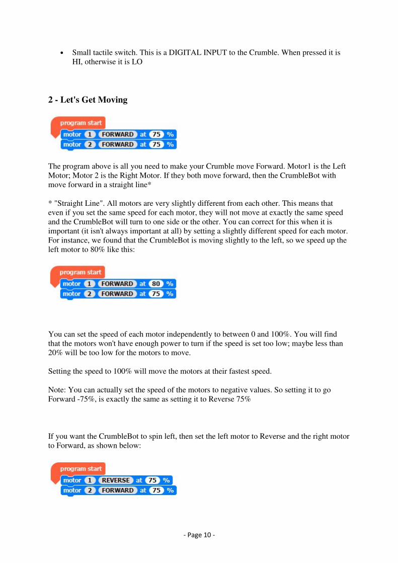
2 - Let's Get Moving
The program above is all you need to make your Crumble move Forward. Motor1 is the Left
Motor; Motor 2 is the Right Motor. If they both move forward, then the CrumbleBot with
move forward in a straight line*
* "Straight Line". All motors are very slightly different from each other. This means that
even if you set the same speed for each motor, they will not move at exactly the same speed
and the CrumbleBot will turn to one side or the other. You can correct for this when it is
important (it isn't always important at all) by setting a slightly different speed for each motor.
For instance, we found that the CrumbleBot is moving slightly to the left, so we speed up the
left motor to 80% like this:
You can set the speed of each motor independently to between 0 and 100%. You will find
that the motors won't have enough power to turn if the speed is set too low; maybe less than
20% will be too low for the motors to move.
Setting the speed to 100% will move the motors at their fastest speed.
Note: You can actually set the speed of the motors to negative values. So setting it to go
Forward -75%, is exactly the same as setting it to Reverse 75%
If you want the CrumbleBot to spin left, then set the left motor to Reverse and the right motor
to Forward, as shown below:
- Page 11 -
If you want the CrumbleBot to spin right, then do the opposite: set the left motor to Forward
and the right motor to Reverse:
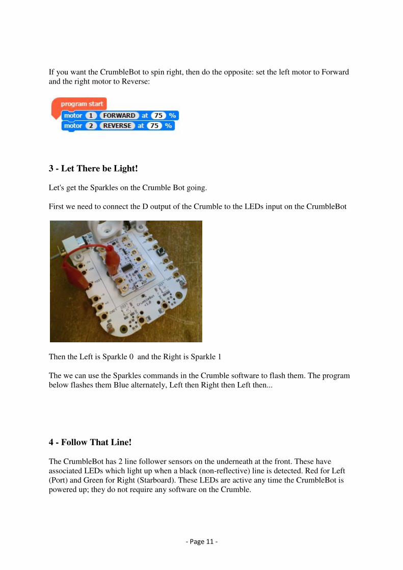
3 - Let There be Light!
Let's get the Sparkles on the Crumble Bot going.
First we need to connect the D output of the Crumble to the LEDs input on the CrumbleBot
Then the Left is Sparkle 0 and the Right is Sparkle 1
The we can use the Sparkles commands in the Crumble software to flash them. The program
below flashes them Blue alternately, Left then Right then Left then...
4 - Follow That Line!
The CrumbleBot has 2 line follower sensors on the underneath at the front. These have
associated LEDs which light up when a black (non-reflective) line is detected. Red for Left
(Port) and Green for Right (Starboard). These LEDs are active any time the CrumbleBot is
powered up; they do not require any software on the Crumble.
- Page 12 -
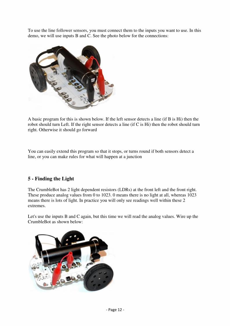
To use the line follower sensors, you must connect them to the inputs you want to use. In this
demo, we will use inputs B and C. See the photo below for the connections:
A basic program for this is shown below. If the left sensor detects a line (if B is Hi) then the
robot should turn Left. If the right sensor detects a line (if C is Hi) then the robot should turn
right. Otherwise it should go forward
You can easily extend this program so that it stops, or turns round if both sensors detect a
line, or you can make rules for what will happen at a junction
5 - Finding the Light
The CrumbleBot has 2 light dependent resistors (LDRs) at the front left and the front right.
These produce analog values from 0 to 1023. 0 means there is no light at all, whereas 1023
means there is lots of light. In practice you will only see readings well within these 2
extremes.
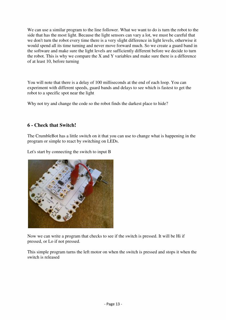
Let's use the inputs B and C again, but this time we will read the analog values. Wire up the
CrumbleBot as shown below:
- Page 13 -
We can use a similar program to the line follower. What we want to do is turn the robot to the
side that has the most light. Because the light sensors can vary a lot, we must be careful that
we don't turn the robot every time there is a very slight difference in light levels, otherwise it
would spend all its time turning and never move forward much. So we create a guard band in
the software and make sure the light levels are sufficiently different before we decide to turn
the robot. This is why we compare the X and Y variables and make sure there is a difference
of at least 10, before turning
You will note that there is a delay of 100 milliseconds at the end of each loop. You can
experiment with different speeds, guard bands and delays to see which is fastest to get the
robot to a specific spot near the light
Why not try and change the code so the robot finds the darkest place to hide?
6 - Check that Switch!
The CrumbleBot has a little switch on it that you can use to change what is happening in the
program or simple to react by switching on LEDs.
Let's start by connecting the switch to input B
Now we can write a program that checks to see if the switch is pressed. It will be Hi if
pressed, or Lo if not pressed.
This simple program turns the left motor on when the switch is pressed and stops it when the
switch is released
- Page 14 -
7 - Adding Extra Sensors - Obstacle Avoider
The CrumbleBot has 2 holes near the front that you can use to add sensors. In this section we
are using the microswitch kit to add obstacle sensors to the CrumbleBot.
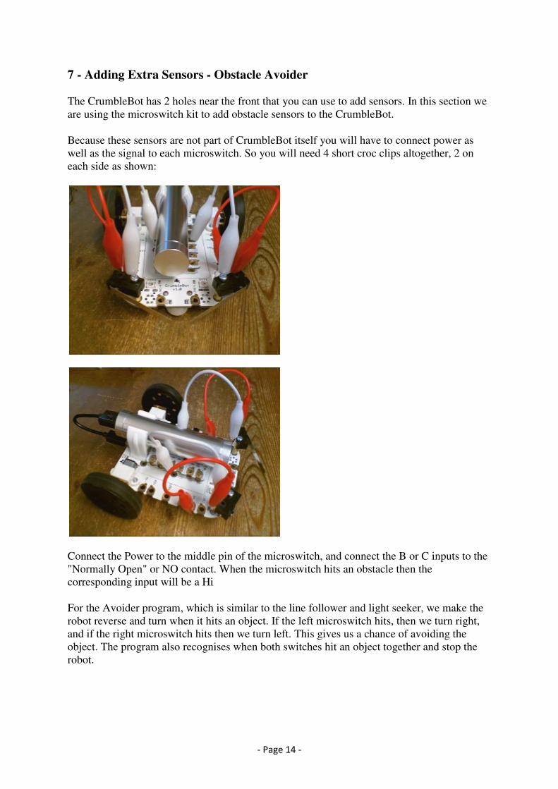
Because these sensors are not part of CrumbleBot itself you will have to connect power as
well as the signal to each microswitch. So you will need 4 short croc clips altogether, 2 on
each side as shown:
Connect the Power to the middle pin of the microswitch, and connect the B or C inputs to the
"Normally Open" or NO contact. When the microswitch hits an obstacle then the
corresponding input will be a Hi
For the Avoider program, which is similar to the line follower and light seeker, we make the
robot reverse and turn when it hits an object. If the left microswitch hits, then we turn right,
and if the right microswitch hits then we turn left. This gives us a chance of avoiding the
object. The program also recognises when both switches hit an object together and stop the
robot.