crosszig: combating cross-technology … combating cross-technology interference in low ......
TRANSCRIPT

CrossZig: Combating Cross-TechnologyInterference in Low-power Wireless Networks
Anwar Hithnawi, Su Li∗, Hossein ShafaghDepartment of CS, ETH Zurich, Switzerland
∗EPFL Lausanne, Switzerland{hithnawi, shafagh}@inf.ethz.ch ∗[email protected]
James GrossKTH Royal Institute of Technology
Stockholm, [email protected]
Simon DuquennoyINRIA Lille, France
and SICS Swedish [email protected]
Abstract—Low-power wireless devices suffer notoriously fromCross-Technology Interference (CTI). To enable co-existence,researchers have proposed a variety of interference mitigationstrategies. Existing solutions, however, are designed to work withthe limitations of currently available radio chips. In this paper,we investigate how to exploit physical layer properties of 802.15.4signals to better address CTI. We present CrossZig, a cross-layersolution that takes advantage of physical layer information andprocessing to improve low-power communication under CTI. Tothis end, CrossZig utilizes physical layer information to detectpresence of CTI in a corrupted packet and to apply an adaptivepacket recovery which incorporates a novel cross-layer basedpacket merging and an adaptive FEC coding. We implementa prototype of CrossZig for the low-power IEEE 802.15.4 ina software-defined radio platform. We show the adaptabilityand the performance gain of CrossZig through experimentalevaluation considering both micro-benchmarking and systemperformance under various interference patterns. Our resultsdemonstrate that CrossZig can achieve a high accuracy in errorlocalization (94.3% accuracy) and interference type identification(less than 5% error rate for SINR ranges below 3 dB). Moreover,our system shows consistent performance improvements underinterference from various interfering technologies.
I. INTRODUCTION
In recent years, we have witnessed a proliferation of het-erogeneous wireless technologies operating in the unlicensedbands. The escalation of wireless demand has put enormouspressure on available spectrum which exacerbates interferenceand coexistence problems [1]–[3].Problem. Embedded computing devices are increasinglyintegrated in objects and environments surrounding us, pavingthe way for the Internet of Things’ vision of digitizing thephysical world. These devices utilize low-cost sensors for arange of performance-sensitive applications, such as healthsystems, general monitoring and tracking, home automation,etc. Low-power wireless1 technologies (e.g., BLE, 802.15.4,and backscatter communication) employed by these applica-tions are expected to endure interference from other radiotechnologies. The CTI problem is exacerbated for these low-power networks, where energy and complexity constraintsprohibit the use of sophisticated interference suppression andcancellation techniques that are finding their ways into uncon-strained wireless systems [3], [4].
1In the context of this paper, we use the term low-power wireless technolo-gies to refer to devices transmitting with less than 0 dBm power.
Due to the inherent application requirements, devices oper-ating in the unlicensed bands transmit at different power levels.Low-power radios typically transmit at less than 1 mW forenergy efficiency requirements, others, such as analog phones,can transmit at the maximum allowed power (i.e., 1000 mW).This severe power asymmetry poses significant coexistenceproblems, where high-power interferers can completely starvelow-power technologies. That is because a typical high-powerinterferer might fail to detect the transmission of a nearbylow-power transmitter, thus can interfere with the low-powernode’s transmission and monopolize the shared channel.
Wireless systems use a variety of physical layer techniquesto combat channel impairments such as attenuation, multipath,or fading. For instance, 802.15.4 employs spread-spectrummodulation and error control coding. However these tech-niques alone fall short in mitigating the effects of CTI. CTIseverely reduces the Signal-to-Interference-plus-Noise Ratio(SINR) of the intended transmission, which results in highbit-error rates and limits the effectiveness of these techniques.Most CTI interferers leave the channel recurrently idle forshort times [3], [5]. This pattern results in partial overlapwith transmitted 802.15.4 packets. The overlap duration istechnology/application specific and is reflected on the errorcharacteristics of residual errors in the interfered packets. Inthis work, we design a recovery mechanism that is aware ofthe characteristics of the CTI residual errors.Approach. In this paper, we argue that there exists sufficientunutilized opportunities for low-power wireless networks tocoexist in overlapping channels. We thoroughly investigatehow to best exploit physical layer (PHY) information to makeinsightful adaptation decisions. PHY information is availablebut inaccessible in commercial off-the-shelf low-power radiochips due to conventional network layering abstractions thatdefine the current layer interfaces and the flow of informa-tion between these layers. We introduce CrossZig, a cross-layer solution that enables low-power wireless nodes to makeinformed decisions on their coexistence strategies based onricher physical layer information, thus adapt autonomouslyto the current interference patterns in the channel. CrossZigachieves this by leveraging two key building blocks:
(a) CTI Detection: This component resides in the phys-ical layer. It detects interference in corrupted packets anddifferentiates its type between Intra- and Cross-TechnologyInterference.

(b) CTI-aware Packet Recovery: We propose an adaptiverecovery scheme, which exploits physical layer hints to adjustthe recovery settings. We propose a packet recovery mecha-nism that exploits time-diversity combining, targeted for low-power single-antenna radios. On top of diversity combining,our scheme applies adaptive Forward Error Correction (FEC)coding with redundancy derived from observed error patterns.
We have implemented a prototype of CrossZig for low-power 802.15.4 radios in a Software-Defined Radio (SDR)platform. Experimental results show that our approach cansubstantially improve the performance of 802.15.4 links undervarious CTI patterns.Contribution. This paper makes the following contributions:• We develop a novel lightweight technique that allows
low-power nodes to recognize the type of interference ininterfered packets. Our design achieves high accuracy indetecting CTI at all SINR ranges where the target signalcannot be decoded correctly and it does not require anyprior synchronization between nodes (unlike [6], [7]);
• We propose an adaptive recovery mechanism that exploitsboth block-based error correction and packet mergingthrough diversity combining at the signal level. We showthat both these schemes come at low complexity costswhile - if carefully performed - they can effectively al-leviate the damage due to Cross-Technology Interference;
• We implement and evaluate a prototype of our systemin SDR using GNURadio [8] with USRP-N210 [9]. Theevaluation results show that our design has consistentimprovements in packet reception ratio under interferencefrom various interferer types.
II. BACKGROUND
In order to mitigate the impact of CTI, we need to developa detailed understanding of how radio technologies interact. Inthis section, we summarize key features of wireless technolo-gies operating in the ISM bands. Moreover, since CrossZig isin part a physical layer design, we review related aspects ofthe conventional 802.15.4 physical layer.
A. Cross-Technology Interference
The broadcast nature of the wireless medium makes it inher-ently vulnerable to interference from spatially close concurrenttransmissions that overlap in time and frequency. This problemelevates in the ISM bands where the number and diversityof inhabited wireless networks are continuously increasing.The FCC’s light regulations to confine interference have notprevented a range of interference problems across the wirelesstechnologies operating in the ISM bands. Classical coexistencesolutions largely focus on avoiding interference by employingcarrier sense (a simple access mechanism that supports at-tentive accommodating of other transmitters) or transmittingover orthogonal channels. These solutions, however, can makelow-power technologies more prone to starvation or are nolonger feasible given the scarcity of interference free channels,respectively. Moreover, many wireless technologies today have
Amplitude
Half-Sine O-QPSK
Modulator
I-Phase
Q-Phase
Half chip offset: Ts
Chip
c0
c2
c4
c6
c1
c3 c5
Fig. 1. IEEE 802.15.4 modulation (O-QPSK).
adopted greedy practices to cope with their high throughputdemands and to better exploit the shared spectrum, such as(a) allocating wide-bands, (b) transmitting at high-power, and(c) frequency agility [4], [10]. These solutions exacerbate theCTI problem for low-power networks.
The dominant spectrum access modality that exists in theISM bands is comprised of non-persistent interferers; whereRF technologies exhibit a time-variant ON and OFF patternof energy emission due to their underlying communicationprimitive, such as frequency hopping, inter-frame spacing(e.g., SIFS, DIFS), back-off slots, application traffic patterns,and periodic cycles of noise radiation, as for microwave ovens.Therefore, they leave the occupied channel recurrently idle forshort times. The ratio of idle periods depends on the interferertechnology and the application traffic patterns. Medium accessmechanisms utilizing these holes in occupied channels canenhance spatial reuse and network throughput.Intra- vs. Cross-Technology Interference: We briefly explainwhy physical layer solutions that are used to tackle intra-technology interference, namely Interference Cancellation(IC) [7], [11], [12] are not applicable in case of CTI. Themain challenge that hinders the use of IC across different tech-nologies stems from the fact that IC depends on the receivercapability of estimating the channel coefficients between Txand Rx and understanding the interfered signal structure(i.e., being able of demodulating and decoding). Only thenthe interference signal can be reconstructed and subtracted.This, consequently, reduces the contribution of interferencesignal on the SINR to a level where the target signal canbe successfully decoded. However, applying IC for the caseswhere the estimation of the interfering signal is erroneous(e.g., CTI) would worsen the chances of decodability for thetarget signal.
B. IEEE 802.15.4 Physical Layer
The IEEE 802.15.4 standard [13] allocates 16 channels fordevices operating in the 2.4 GHz ISM band, where each chan-nel has a bandwidth of 2 MHz. At the physical layer, data isfirst grouped into 4-bit symbols and then spread to a specified32-bit long Pseudo-random Noise (PN) sequence (b0b1b2b3 →c0c1c2 . . . c31). Each bit (ci) in a PN sequence is then modu-lated using Offset Quadrature Phase-Shift Keying (O-QPSK).As shown in Fig. 1, the even chips c0c2c4 . . . are modulatedas In-phase (I) component of the carrier and the odd indexedchips c1c3c5 . . . are modulated as Quadrature (Q) componentof the carrier. The time duration of each chip is 1 µs andthere exists a half chip time (Ts = 0.5 µs) offset between theQ-phase chips and I-phase chips that results in a continuous

Standard mode
CTI detection
CRC fail
No CTI
Observa- tion mode
CTI detected CPM
RS-adaptive + CPM
PRR < thr
PRR ≥ thr
No CTI
No CTI
Fig. 2. Overview of CrossZig.
phase change and constant envelope. For demodulation, thereceiver’s radio converts each half-sine pulse signal into a chip.Then these chips are grouped to provide PN sequences. Thede-spreading is performed by mapping the PN sequence tothe symbol with the highest correlation. Unlike modulationschemes such as QAM or ASK, which operate by varyingthe amplitude of the carrier wave, 802.15.4 adopts O-QPSKmodulation. Hence, the carrier wave amplitude of all chipswithin one packet is constant and depends on the selectedtransmission power (i.e., constant envelope). The 802.15.4chips are shaped by half-sine pulse at the transmitter. While thesignal’s shape will be distorted by noise in the wireless chan-nel, its basic shape is maintained. The demodulator’s outputprovides an indicator of how close the received signal shapeis to the expected shape, we elaborate more on this in §III-B.We leverage these two features (i.e., constant amplitude andsignal shape) of the 802.15.4 PHY in the design of CrossZig.
III. ARCHITECTURE AND DESIGN
In this section, we present the detailed design of ourapproach that extends the 802.15.4 stack to improve mediumaccess efficiency under CTI and recover partially interferedpackets. We start by presenting a high-level overview ofCrossZig, then present its core components, and finally de-scribe the system integration.
A. Overview
CrossZig is an extension to the standard 802.15.4 that allowslow-power wireless nodes to communicate better in interferedenvironments. Upon the detection of CTI, CrossZig triggersan adaptive recovery scheme. Our extension is accompaniedby a CTI-aware medium access mechanism that opportunisti-cally leverages the silence duration in interfered channels. Inparticular, our extension consists of the following components:PHY-hints Interface. This interface allows higher layers toaccess richer physical layer information and consequently useit in a variety of algorithms to boost performance under CTI.CTI Detection. This component resides in the physical layer.It exploits variations in the PHY hints to detect interference inincoming corrupted packets. More importantly, it differentiatesthe interference type between Intra- and Cross-TechnologyInterference. The error localization and recovery mechanismpresented next are enabled by CrossZig only when CTI isdetected; otherwise nodes operate in the normal mode, asdepicted in Fig. 2.Symbol Error Localization. This component allows to locateand identify erroneous symbols by solely relying on PHY hints
Quadrature Demodulation Time Recovery
Chip-to-Symbol 1
0 !!!!!!!!Symbol-to-Bit
Soft Values
Chips Symbol
Hamming Distance
Energy Detection
Binary Data
Fig. 3. Block Digram of the receiver and corresponding PHY hints.
without additional signaling or redundancy. This is necessaryfor our introduced recovery mechanisms.CTI-aware Packet Recovery. Our system recovers from avariety of interference patterns. The receiver estimates errorsin interfered packets by relying on physical layer hints. Errorinformation is used to choose a suitable recovery mechanism;currently selecting or combining two recovery mechanisms:(a) Cross-layer based packet merging to recover long errorbursts, and (b) Adaptive error-correction coding to deal withtransient interference with low BER rates.
B. Physical Layer Hints
When an interfered signal is received, besides standardprocessing, such as demodulation, chip-to-symbol mapping,and delivering decoded symbols to the data-link layer, thephysical layer also accommodates further hints that can beexploited to boost the performance of wireless systems [14]–[17]. In our design, we exploit such hints to detect Cross-Technology Interference and to estimate the confidence ofreceived symbols in interfered packets, as depicted in Fig. 3.We consider the following physical layer hints:Signal Power. When two signals interfere, their energiesadd up2. Therefore interfered segments of the received signalexperience larger power than the rest of the signal. Theinterfered segment of the signal exhibits lower SINR, thusexperiences a higher error rate. This insight on additive energyof interfering signals highlights the ambient information thesignal carries along and can assist in detecting interferenceand localizing interfered symbols within interfered packets.Fig. 4(a) plots the signal power of a partially interfered packet.Once exposed to interference, the signal experiences a suddensharp increase in the signal power.Hamming Distance. In the 802.15.4 PHY, symbols are spreadto a 32-chip codeword before transmission (one of 16 PNcodewords). The de-spreading is performed by mapping thereceived codeword to the symbol with the highest correlation.For an erroneous mapping of a received codeword, manychips have to be flipped. The distance between the input andoutput codewords of the chip-to-symbol mapper can serve asindicator for the confidence of symbol decoding. Fig. 4(b)plots the Hamming distance within an interfered packet. Largeand low Hamming distance values provide a good indicator ofcorrupted or correct symbols, respectively.Demodulation Soft Values. Soft Values (SV) of demod-ulated bits are real numbers output by the demodulator.These values are approximations of the transmitted symbols.
2This occur if the signals add up constructively.

0 50 100 150 2006yPbols
0.00.10.20.30.40.50.6
3ow
er [P
W]
(a) Power.
0 50 100 150 2006ymbols
02468
101214
HDm
min
g D
istD
ncH
(b) Hamming distance.
0 50 100 150 200SymbolV
14
14
34
Soft
Val
ue [π
]
(c) Absolute Soft values.
Fig. 4. Physical layer hints of a corrupted packet by Interference. The gray area indicates erroneous symbols.
The receiver’s demodulator maps the SV to the closest idealsymbol. For instance in case of Binary Phase-Shift Keying,the binary demodulated bits are retrieved after passing the softvalues through a binary slicer. The bit is set to 1, if the SV is apositive number, otherwise it is set to 0. However, besides thebit value, SV also contains the confidence information aboutthe demodulation [14].
The confidence information of the SV can be interpretedbased on the type of the demodulator. In case the receiveradopts a matched filter-based coherent demodulator, the softdemodulated values indicate the similarity between the re-ceived signal and ideal signal shape. Thus the larger SVs, thehigher the confidence for the corresponding bit to be correctlydemodulated. However, if a non-coherent demodulator is used,the SV carries different information. For example, in our casethe receiver uses a quadrature demodulator, which outputs thephase differences between two successive signal samples asSVs and can be computed as:
SV (i) = ](s(i)× s∗(i− 1)) = ±π4
+ δ, (1)
where ±π4 is the ideal value of SV and δ is error caused byinterference and noise. Each chip is modulated by a singlehalf-sine pulse in the transmitted signal and is representedby a sequence of four complex samples at the receiver. Thisimplies a total phase change of π for one chip, hence theexpected phase change between two signal samples is ±π4 . Thedemodulation confidence does not dependent on the absolutevalue of SV, but the difference between |SV | and π
4 . Chips(i.e., bits of a codeword) with |SV | closer to π
4 have a higherprobability to be correctly demodulated (see Fig. 4(c)).
C. CTI Detection
Performance degradation in wireless systems can be dueto Intra-Technology Interference, Cross-Technology Interfer-ence, or insufficient signal strength. Determining the causeof performance degradation is essential for the coexistenceproblem as this defines the corresponding mitigation actionto be considered. Discerning the cause of packet corruptionwhile exposing differences between interference and weaksignal has been addressed in recent works. This is mainlyachieved by relying on soft value jumps or power jumpswithin received packets. However, differentiating Intra- andCross-Technology Interference has not yet been addressedwith practical mechanisms. The inability to distinguish thetype of interference leads to rather conservative approachesthat blindly treat packet losses as collisions (i.e., overlapping
transmissions of the same technology). Thereby exponentialbackoffs are invoked which can lead to starvation of low-power radios competing with high-power interferers. More-over, interference cancellation-based solutions (e.g., SIC [11])would impose undesired overhead and worsen the chances ofdecodability for the target signal, if applied in the presenceof CTI. Generally speaking, bracing wireless nodes withmechanisms that increase their ability to reason about thechannel state will allow better adaptation and recovery.
Hence, beyond detecting the presence of interference, weare interested in detecting the presence of CTI. We introducetwo complementary CTI detection mechanisms that are uti-lized in CrossZig: SV-based and correlation-based detections.Introduced recovery mechanisms are only enabled by CrossZigwhen CTI is detected
1) SV-based Detection: We explore the possibility of ex-ploiting variations in demodulated soft values for interferencetype detection. The core idea is to inspect the modulation andsignal shape of the interfered signal, which is reflected by thesoft values. While experiencing Intra-Technology Interference(interferer is 802.15.4), the demodulator demodulates thestronger signal. Since the interference signal is of the sametype (i.e., shape) the variations in the soft values remain small.In contrast, with Cross-Technology Interference the signalshape differs from the ideal signal. Thus, the variations in softvalues are higher. We take signal samples from the interferedpart and compute the variation metric V which we use todetermine the received signal type:
V =1
N
N∑i=1
(|SV (i)| − π
4
)2(2)
V measures the average distance between the received |SV |and the ideal value π
4 . The smaller V , the higher the chancethat the signal is 802.15.4 (i.e., Intra-Technology Interference).
This SV-based detection mechanism does not require tocompute complex compensation of channel distortions orsignal decoding. Moreover, the soft values are readily avail-able which makes this detection mechanism considerablylightweight. Note that any interfering technology using O-QPSK with half-sine pulse shape and similar baseband sig-nal bandwidth other than 802.15.4 is identified as Intra-Technology Interference using this mechanism. This techniqueexploits the capture effect phenomenon, in which a stronginterfering signal is successfully demodulated (i.e., of the sametechnology). It, therefore, works well in the low SINR region,where the target signal is much weaker than the interferer.

Hence, the interference signal dominates the signature shapein the received signal. If this is not the case, we resort to amore costly technique: correlation-based detection. Althoughwe focus our discussion on 802.15.4 PHY, this approach canbe adopted to other wireless technologies that provide SVs.
2) Correlation-based Detection: The receiver can exploitthe fact that 802.15.4 packets start with a predefined preambleand SFD symbols for synchronization, and search for thisknown signal pattern within the interfered segment by com-puting the temporal cross-correlation between received signaland the ideal preamble plus the SFD. In case the pattern ispresent, the receiver can conclude that the interference is oftype Intra-Technology Interference. Otherwise, it is a Cross-Technology Interference. In general, correlation is a typicalfunctionality in standard wireless receivers [18]. To detectthe interference type in the received signal, the receiver canperform the cross-correlation between the 802.15.4 preamble(p) and the start of the interfered segment. This approach yieldsa good performance in theory.
In practice, however, the transmitter and receiver are typi-cally not centered on the same frequency, hence there is a smallfrequency offset (∆f ) between the transmitter and the receiverthat causes a linear shift in the phase of the received signal.This frequency offset can distort the correlation and needsto be compensated prior to the correlation process. Standardreceivers typically estimate the offset and compensate forit. In the context of CTI, since we are agnostic of thetransmission source and do not have access to a decodablepilot or decodable preamble in the interfered signal, it is notpossible to compensate the frequency offset of the interferencesignal, even in case of Intra-Technology Interference. This con-sequently limits the accuracy and usability of this approach.
An alternative approach is applying correlation in the fre-quency domain. Since frequency offset in the time domainwill translate into sampling offset in the frequency domain,it does not affect the value of correlation, but only shift it.The frequency domain correlation with consideration of thefrequency offset can be formulated as follows:
c(y, τ, p) =N∑n=1
P ∗(n)Y (n+ τ) (3)
=
N∑n=1
P ∗(n)F(
(s(k) + i(k) + w(k))ej2π(∆f−τ)kT)
(4)
The ideal preamble is independent of transmitted data andthe noise, therefore the correlation between the ideal preambleand s and w is about zero.
c(y, τ, p) =N∑n=1
P ∗(n)F(i(kT )ej2π(∆f−τ)kT
)(5)
=
N∑n=1
P ∗(n)I(n+ τ −∆f) (6)
Where P (n) and Y (n) are the ideal preamble signal andreceived signal in the frequency domain, respectively. F(x)means the Fourier transform of x. Moreover, s, i, and wrepresent signal, interference, and noise in the received sig-nal, respectively. The correlation value is maximized when
Fig. 5. Physical layer hints for correct and corrupted symbols under wirelesscamera interference. Dark grey dots indicate correct symbols and light greydots indicate corrupted symbols. The majority of received symbols withHamming distance under 4 were received correctly and above 10 corrupted.Correct and corrupted symbols overlap in the Hamming distance range inbetween. Therefore, the Hamming distance alone is not sufficient for thedetermination of the symbol fate and the power information can help forthese symbols.
τ = ∆f , and the signal is the expected preamble signal(I(n) = P (n)). Since ∆f is unknown and we cannot com-pensate it, we compute the correlation for a certain range ofτ instead and consider its maximal value as:
C(y, p) = maxτ
c(y, τ, p) (7)
The range of τ is not large, given that the frequency offset istypically small.Complexity. Applying correlation in the frequency domaininvolves transforming a signal from its time representationto the frequency domain ahead of applying the correlation,which can be an expensive procedure for low-power receivers.CrossZig primarily runs the SV-based mechanism for detectionand utilizes the correlation-based technique just for the SINRranges where the SV-based technique does not yield a goodaccuracy. The SV-based mechanism in its core examinesvariations in the SVs which makes it a lightweight mechanismthat is practical for low-power radios.
D. Symbol Error Localization (in interfered packets)
As CrossZig involves processing of incomplete packets(partially interfered), it requires the receiver to be able todiscern with a high accuracy and without additional feedbackfrom the sender which symbols in a packet are correct andwhich are not. The physical layer hints described in §III-Bexpose statistical differences between interfered and non-interfered symbols, which render them suitable candidates todetect erroneous symbols. However, designing practical errordetection algorithms based on these PHY hints with acceptablefalse positive and false negative rates is challenging. As weare interested in per symbol error estimation, we leave out SV(which would introduce more overhead with one SV per chip,i.e., 32 per symbol).
A direct method to estimate the symbol error is settinga threshold on the number of unmatched bits (reflected inHamming distance) of the decoding results. This indicates thedisparity between the chip sequence derived from the received

Retransmitted signal
Original signal
Combined output
Target signal is enlarged Interference counteracted
Time
Time
Time
Fig. 6. Diversity combining of two identical signals under interference.
signal and ideal symbol sequence. However, finding a goodthreshold is not trivial, as discussed before and illustrated inFig. 4(b). We propose an error estimation algorithm that jointlyuses the number of unmatched bits of decoding results and thereceived signal power.
Fig. 5 shows the power mean, power variance, and Ham-ming distance for correct and corrupted symbols for one ofour traces (we detail in §V our experiment setup). This plotcaptures the intuition behind our algorithm; for low and highHamming distances, we can classify a symbol with a highconfidence as successfully decoded or corrupted, respectively.For intermediate values, the Hamming distance alone is notenough (as dark and light gray dots indicating correct andcorrupted symbols, respectively, overlap in this Hammingdistance range in Fig. 5). The input power though can assistto detect corruption for these cases.
Our symbol error detection algorithm works as follow: Asymbol is classified as correct if its Hamming distance islower than τl, whereas those with Hamming distance ≥ τh areclassified as erroneous symbols. For symbols with a Hammingdistance between the decision boundaries τl and τh, we checkthe channel SINR. In case SINR is lower than τs, we mark thesymbol as erroneous. The SINR measures the channel noiseand interference, it therefore reflects to what extent the channelpreserves the correlation between transmitted and receivedsymbols. We find this joint estimation method to be slightlybetter and much stabler than just setting a threshold on thenumber of unmatched bits. The threshold values (τl, τh, τs) areconfigurable system parameters which we derive empirically.
E. CTI-aware Packet Recovery:
CrossZig mitigates CTI through an adaptive packet recoveryscheme. It observes error characteristics and adjusts the re-covery mechanism settings accordingly. The recovery schemeintegrates two recovery mechanisms, namely cross-layer basedpacket merging and adaptive RS coding. Cross-layer packetmerging tackles long burst errors which are beyond codingrecovery capabilities. Adaptive RS coding targets packets thatcan be recovered with moderate code redundancy, i.e., lowbit error ratio. We first explain how these mechanisms workindependently and later we describe how they are integratedin CrossZig.Cross-layer based Packet Merging (CPM). Recoveringpackets with high error rate with coding is inefficient or even in
Lc
Fig. 7. Two consecutive corrupted transmissions of the same packet. Lchighlights the overlapped interfered segment in the two packets which cannotbe recovered with basic packet merging. We exploit MRC to recover thesegment Lc.
some cases not feasible. Hence, once such pattern is detected,our adaptive mitigation scheme instructs the use of CPM.
Our CPM is realized at two stages; symbol level andsignal level. The symbol-level packet merging reconstructsthe target packet by combining correct symbols from twopacket instances. CrossZig identifies correct symbols usingour error localization mechanism. As long as we receiveone correct instance of every symbol, this technique allowsus to reconstruct the original packet with high confidence.For symbols that are corrupted on all received instances (seeFig. 7), we combine at the signal level by means of MaximumRatio Combining (MRC).
In MRC [19], each signal branch is multiplied by a weightfactor that is proportional to the branch SINR. That is,branches with strong SINR have a larger weighted factor andare further amplified. The signal and noise power are com-puted over interference-free PHY header and SFD symbols.Thus, interference signal power is derived as the differencebetween the approximated target signal and noise power frominterfered signal power. Signals of the first transmission andthe corresponding retransmission can be represented as:
y1(t) = s1(t) + i1(t) + n1(t) (8)
y2(t) = s2(t) + i2(t) + n2(t) (9)
The maximal combined signal can be represented as:
y(t) = w1y1(t) + w2y2(t) (10)
where the weighted coefficients (w1, w2) are computed by theSINR over the sum of signals of commonly corrupted symbols:
wj =SINRj∑SINRi
(11)
Time diversity involves transmitting the same informationin two distinct times. In Equations 8 and 9, sj , ij , nj representsignal, interference, and noise components of the receivedsignal at time instant j. The noise in each time instance of thechannel is independent of the signal. The signals s1 and s2are essentially identical. In contrast, i1 and i2 are not identicaland most probably completely uncorrelated.
After combining, target signal s components are amplified.This yields an increase in the power of the target signal, thusincreases its decodability chances. Interference i and noise ncomponents can be either canceled, attenuated, or amplified;However on average, the SINR is increased (see Fig. 6).
For the MRC-based combining, co-phasing of all sig-nals is necessary to avoid target signal cancellation. In-stead of performing computationally complex frequency and

Quadrature Demodulator
Clock Recovery MM
Chip-to-Symbol Mapper
CRC CRC
Error Localizer
Symbol Error Estimator
Adaptive Recovery
RS-Decoder
Packet Recovery
Channel
RS-Encoder
Half-Sine
Shaper
O-QPSK Modulator
Symbol-to-chip mapper
Header Header
Tx Rx
Ana
log
P
HY
Ana
log
P
HY
RF
Fr
onte
nd
Ana
log
P
HY
RF
Fr
onte
nd
Interference Detection
Link
Lay
er
Phys
ical
Lay
er
PHY Hints Interface
Fig. 8. Cross-Layer architecture design of CrossZig. Dark gray shaded boxesdepict our components added to standard 802.15.4 stack.
initial phase offset compensation for each signal, we estimatethe relative phase offset between two signals. Since they aretransmitted and received by the same sender and receiver, theirfrequency offsets are the same. Thus, after compensating therelative phase offset by utilizing the preamble signals in eachpacket, we can correctly align them.RS-Adaptive Coding. When the system observes high ratioof corrupted packets, FEC, which adds redundant informationto the payload, is used to potentially recover the errorsand possibly avoid retransmissions. Although FEC codes arewidely used in communications systems, selecting the rightcoding scheme and setting the right level of redundancy forconstrained devices is not trivial. We investigate how to derivean adaptive encoding strategy for low-power devices undervarious interference patterns, where transmitted redundancy isbounded to the inferred error patterns.
We choose Reed-Solomon (RS) codes, which are practicalfor constrained devices [20], [21]. RS codes are systematiccodes, i.e., redundancy data is appended to unaltered sourcedata. This results in no decoding overhead when no error ispresent. The RS codes are block-based error correcting. Thelength of the redundant parity (t) defines the maximum numberof corrupted blocks a receiver can successfully recover withina partially corrupted packet. RS coding can correct up to t/2and detect up to t block errors. It works well for error patternsthat fall under the recovery capacity of the parity check.
The primary goal of our adaptive strategy is to increasepacket recovery rates, yet minimize the redundancy overheadon the channel to meet the energy constraints of low-powerradios. To realize this, we infer error information from physicallayer hints, as discussed in §III-D. This allows us to adaptivelyderive a redundancy level based on the symbol error rate inthe window of received packets. In case the number of cor-rupted packets is low (i.e., reasonable Packet Reception Ratio(PRR)), RS-coding is not triggered which allows CrossZig toavoid introducing redundancy overhead in good links. For thewindow wi of observations, we calculate the redundancy levelRi based on the observed degree of corruptions (i.e., Ri isderived from the average number of erroneous symbols percorrupted packet in wi and is bounded by an upper bound(Ri ≤ 1−PRRi
PRRi× packet length)). CrossZig triggers adaptive
33m
Rx
Tx
L1 L2 L3
!!MW
CAM
WiFi
Uncontrolled APs
Fig. 9. Layout of the online evaluation experiment setup. SDR 802.15.4 Rx-Tx located in an office with a line-of-sight link of 5 m. The interferers arelocated at locations L1 (1 m), L2 (4 m), and L3 (7 m), where L1 and L2are in line-of-sight to Rx-Tx and L3 is in non-line-of-sight. Green circlesindicate the location of our multiple interferer scenario. Gray squares indicatethe location of uncontrolled access points placed in the floor.
coding only if Ri is lower than the calculated upper bound.This allows us to ensure that the introduced redundancy isnot significantly higher than potential symbol errors to berecovered. We assume that the corruptions in the upcomingpackets follow the trend of our current observations. Hence,the window size should be selected carefully. In our evaluation,we noticed that window sizes of 300 ms to 1 s result in a goodand stable performance.
F. System Integration
CrossZig extends the basic 802.15.4 PHY and MAC layersas illustrated in Fig. 8. It provides a single hop reliable deliverymechanism that can counter the CTI effects. The receiverperforms packet detection and decoding in a manner similarto the standard 802.15.4. In case a jump in the signal strengthis observed during packet reception and the received packetfails the CRC, the receiver initiates the interference detectionalgorithm discussed in §III-C. If CTI is detected, the trans-mitter adapts the Channel Clear Assessment (CCA) thresholdto allow an opportunistic access to the channel. Upon thereception of few partially interfered packets, the system adjuststhe initial recovery settings for the next observation windoww. Any notable changes on the observed error characteristicstrigger the system to adjust the recovery settings.
CrossZig performs the following logic while adjusting therecovery settings. Packet retransmission always carry a fixed,low level of redundancy code. This is used to boost the perfor-mance of our CPM: the packets are merged, lowering the BERto a level recoverable with FEC. In case of high packet cor-ruption levels (low PRR, in our settings lower than 75%), RS-adaptive coding is triggered. Here, the redundancy R is derivedadaptively based on the observed degree of corruptions. R isderived from the average number of erroneous symbols percorrupted packet in the observation window. Hence, the codingis adapted according to the dynamic interference patterns in thechannel. When a packet cannot be recovered with the currentredundancy level, CPM is applied.
IV. IMPLEMENTATION
We build a prototype of CrossZig using SDR. For theSDR hardware, we rely on the USRP-N210 [9], equippedwith an SBX radio daughterboard [22] as radio front-end.
Wireless Camera Wifi-Light Wifi-High Microwave Oven Multiple-1 Multiple-2 Multiple-3 All0.00.10.20.30.40.50.6
Packet Recovery [ratio]
05
1015202530
FEC Overhead per Packet [Byte]
0.00.20.40.60.8
Goodput [ratio]
RS-Fixed RS-Adaptive Packet Merging CrossZig
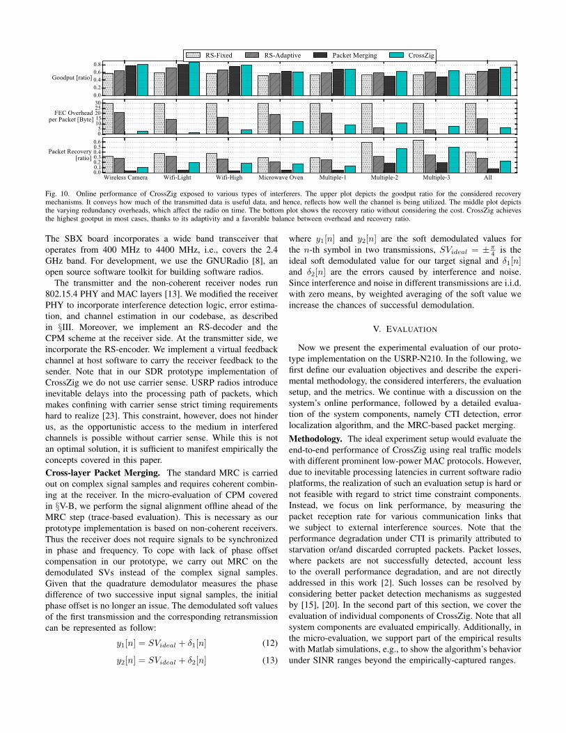
Fig. 10. Online performance of CrossZig exposed to various types of interferers. The upper plot depicts the goodput ratio for the considered recoverymechanisms. It conveys how much of the transmitted data is useful data, and hence, reflects how well the channel is being utilized. The middle plot depictsthe varying redundancy overheads, which affect the radio on time. The bottom plot shows the recovery ratio without considering the cost. CrossZig achievesthe highest gootput in most cases, thanks to its adaptivity and a favorable balance between overhead and recovery ratio.
The SBX board incorporates a wide band transceiver thatoperates from 400 MHz to 4400 MHz, i.e., covers the 2.4GHz band. For development, we use the GNURadio [8], anopen source software toolkit for building software radios.
The transmitter and the non-coherent receiver nodes run802.15.4 PHY and MAC layers [13]. We modified the receiverPHY to incorporate interference detection logic, error estima-tion, and channel estimation in our codebase, as describedin §III. Moreover, we implement an RS-decoder and theCPM scheme at the receiver side. At the transmitter side, weincorporate the RS-encoder. We implement a virtual feedbackchannel at host software to carry the receiver feedback to thesender. Note that in our SDR prototype implementation ofCrossZig we do not use carrier sense. USRP radios introduceinevitable delays into the processing path of packets, whichmakes confining with carrier sense strict timing requirementshard to realize [23]. This constraint, however, does not hinderus, as the opportunistic access to the medium in interferedchannels is possible without carrier sense. While this is notan optimal solution, it is sufficient to manifest empirically theconcepts covered in this paper.Cross-layer Packet Merging. The standard MRC is carriedout on complex signal samples and requires coherent combin-ing at the receiver. In the micro-evaluation of CPM coveredin §V-B, we perform the signal alignment offline ahead of theMRC step (trace-based evaluation). This is necessary as ourprototype implementation is based on non-coherent receivers.Thus the receiver does not require signals to be synchronizedin phase and frequency. To cope with lack of phase offsetcompensation in our prototype, we carry out MRC on thedemodulated SVs instead of the complex signal samples.Given that the quadrature demodulator measures the phasedifference of two successive input signal samples, the initialphase offset is no longer an issue. The demodulated soft valuesof the first transmission and the corresponding retransmissioncan be represented as follow:
y1[n] = SVideal + δ1[n] (12)
y2[n] = SVideal + δ2[n] (13)
where y1[n] and y2[n] are the soft demodulated values forthe n-th symbol in two transmissions, SVideal = ±π4 is theideal soft demodulated value for our target signal and δ1[n]and δ2[n] are the errors caused by interference and noise.Since interference and noise in different transmissions are i.i.d.with zero means, by weighted averaging of the soft value weincrease the chances of successful demodulation.
V. EVALUATION
Now we present the experimental evaluation of our proto-type implementation on the USRP-N210. In the following, wefirst define our evaluation objectives and describe the experi-mental methodology, the considered interferers, the evaluationsetup, and the metrics. We continue with a discussion on thesystem’s online performance, followed by a detailed evalua-tion of the system components, namely CTI detection, errorlocalization algorithm, and the MRC-based packet merging.Methodology. The ideal experiment setup would evaluate theend-to-end performance of CrossZig using real traffic modelswith different prominent low-power MAC protocols. However,due to inevitable processing latencies in current software radioplatforms, the realization of such an evaluation setup is hard ornot feasible with regard to strict time constraint components.Instead, we focus on link performance, by measuring thepacket reception rate for various communication links thatwe subject to external interference sources. Note that theperformance degradation under CTI is primarily attributed tostarvation or/and discarded corrupted packets. Packet losses,where packets are not successfully detected, account lessto the overall performance degradation, and are not directlyaddressed in this work [2]. Such losses can be resolved byconsidering better packet detection mechanisms as suggestedby [15], [20]. In the second part of this section, we cover theevaluation of individual components of CrossZig. Note that allsystem components are evaluated empirically. Additionally, inthe micro-evaluation, we support part of the empirical resultswith Matlab simulations, e.g., to show the algorithm’s behaviorunder SINR ranges beyond the empirically-captured ranges.

10 20 30 40 50 605edundancy [ByWe]
0.00.20.40.60.81.0
5ec
Rver
ed [r
aWiR
]All 0ulWiple-3 Wireless-Camera
Fig. 11. The implication of applying fixed levels of redundancy under CTI.The gray-colored area depicts the ranges for recovery ratio under varyinginterferers per technology.
Interferers. Our set of interference sources includes low/highpower, narrow/wide band, channel hopping/fixed frequency,and CSMA/non-CSMA. This represents common underlyingproperties adopted by most radio technologies. More specif-ically, as CTI we consider: 802.11 (heavy and light UDPtraffic), digital wireless camera, and microwave oven. 802.15.4is considered as Intra-Technology Interference.Evaluation Setup. The system evaluation is performed ina typical office building. Fig. 9 shows the layout of the ex-perimental setup. Experiments are carried out with controlledsingle active interferers mentioned above and multiple activeinterferers. Multiple active interferers are different combina-tions of single interferers running simultaneously and definedas: Multipe-1: microwave oven and wireless camera runningsimultaneously, Multipe-2: microwave oven, wireless camera,and 802.11 with light UDP traffic, and Multipe-3: microwaveoven, wireless camera, and 802.11 with heavy UDP traffic. The802.15.4 transmitter-receiver pair was represented by our pro-totype implementation on USRPs. During the experiments, the802.15.4 communication link was also exposed to interferencefrom various uncontrolled sources existing in the building. Ineach experiment, we transmit 6000 packets consecutively with60 Byte payload, at a 10 ms interval.Metrics. Within our evaluation we use the following metrics:(a) Goodput ratio: defines the ratio of useful received dataover total received data. It quantifies the system’s efficiencyas it reflects both the gain and the transmission overheadtogether. This metric allows us to observe how well transmittedbytes are utilized. (b) FEC overhead: indicates the addedtransmission overhead which is directly related to energyefficiency, a vital factor in low-power networks. (c) Packetrecovery ratio: indicates how many of the corrupted packetsour recovery mechanisms could recover. The recovery ratioand redundancy overhead show the performance of the con-sidered schemes compared to the baseline where no mitigationscheme took place. Note that in our definition, the basicscheme has 0 recovery ratio and 0 cost. (d) Precision andRecall: values are relevant for the performance discussion ofsymbol error detection, where selection of parameters has animpact on the performance. Precision indicates how many ofthe identified corrupted symbols are indeed corrupted. Recallindicates how many of the overall corrupted symbols areidentified. (e) Symbol Error Rate (SER): is the number ofcorrupted symbols over the total number of symbols in areceived packet.
−10 −8 −6 −4 −2 0 2 46I1R [dB]
0.00.10.20.30.4
ErrR
r [ra
tiR]
CCF6V
Fig. 12. Error ratio in discerning the type of interference between CTI and802.15.4 achieved by the SV-based method (SV) and the correlation-basedmethod (CCF).
A. System Performance
We expose CrossZig first to single active interferers at dif-ferent distances. The interferers are located first at location L1,then L2, and L3 (see Fig. 9). Second, we consider interferencegenerated from multiple simultaneous sources. Fig. 10 showsthe evaluation results achieved by the following recoveryschemes: RS-coding with fixed redundancy of 30 Byte, ouradaptive coding scheme which selects a redundancy between0 and 30 Byte based on the average observed SER in the500 ms window of observations (irrespective of the PRR inthe channel), packet merging, and finally CrossZig which com-bines our cross-layer based packet merging and our adaptiveRS-coding scheme.
The error patterns caused by interferers vary as we changethe interference types, therefore different experiment settingsyield varying performance in terms of goodput ratio, packetrecovery ratio, and redundancy overhead.
The RS-fixed scheme achieves the highest packet recoveryratio, but this comes with a fixed 30 Byte redundancy perpacket, regardless of channel conditions. This has a negativeimpact on goodput. This overhead exacerbates for good qualitychannel conditions which we did not consider in this study.This results in higher in-air time and increased processing fordecoding at the receiver side, which are both undesirable forlow-power devices. The RS-fixed scheme evaluated in Fig. 10considers 30 Byte redundancy. Fig. 11 depicts the recoveryratio at different fixed redundancy levels. With a redundancyhigher than 20 Byte we do not observe a notable improvementof the recovery ratio. Note that increasing the redundancy hasthe side-effect of increasing the probability of overlap withinterference, hence, reducing the effectiveness. With our RS-adaptive scheme, we observe a similar packet recovery ratioas with the fixed strategy, but at a lower overhead (in average15 Byte for each packet). This yields a higher goodput.
Packet Merging comes with no FEC overhead because itsimply works on the received signal of incoming packets. Itsrecovery ratio is modest in most cases, except in presenceof multiple interferers, because Packet Merging is particularlyeffective at higher SER levels.
CrossZig improves RS-adaptive which relies only on theobserved SER rates for adaptation. In addition CrossZigrecovers long error bursts using Packet Merging and isable to keep its cost low under sparse interference. Wereach an average packet recovery ratio of 23% overalland up to 50%, for instance for the multiple-3 setup.

Fig. 13. Precision-Recall analysis for symbol error estimation with Power(PW), Hamming Distance (HD), and combination of both (PW HD). Precisionindicates how many of the identified corrupted symbols are indeed corrupted.Recall indicates how many of the overall corrupted symbols are identified.
This is about half of the average packet recovery ratio achievedwith the aggressive RS-fixed (40%) over all cases. However,the overall overhead of CrossZig is by a factor of 4.6 lowerthan the other schemes, and reaches up to a factor of about20 for the case of WiFi-light. As a result, CrossZig achievesthe highest goodput ratios in most scenarios. Note that forfairness we did not compare the performance of CrossZig tothe case of no active interferer, where goodput falls drasticallyfor RS-fixed and improves to even higher values for CrossZig.
Conclusion. We show that performing timely adaptation tomatch induced error patterns from external interference ispossible with help of physical layer hints. With this timelyadaptation we can achieve better goodput and avoid excessiveredundancy which comes at high price for low-power devices.
B. Dive in CrossZig
We carry out an offline micro-benchmark analysis ofCrossZig to quantify the performance of its individual compo-nents independently. Our traces for this evaluation include thecomplex signal of 35,875 packets corrupted by interference.
1) CTI Detection: We now discuss the performance of ourCTI detection scheme introduced in §III-C. We estimate theeffectiveness of our scheme in detecting the occurrence ofIntra- and Cross-Technology Interference.
Fig. 12 shows the detection error ratio for both the SV-based and correlation based detection mechanisms. For lowSINR ranges under -2 dB, both mechanisms perform wellwith error rates below 5%. SV-based detection performs wellat low SINR because in case of intra-technology interference,the interfering signal can be demodulated by the receiver andthis is reflected in lower variations of the soft values. As SV-based detection is the cheaper mechanism, we rely on it forSINR under -2 dB. As the SINR increases (weaker interferer),detecting the source of interference is more challenging. Theaccuracy of the SV-based scheme degrades sharply, whilethe correlation-based detection still yields error rates below10%. Therefore, for SINR greater or equal to -2 dB, we usecorrelation-based detection. Note that for SINR ranges above3 dB, the interference signal is very weak and, hence, thetarget signal is decodable. Consequently, CTI detection is notrequired for these SINR ranges.
−20−15−10 −5 0 5 10 15SINR [dB]
0.0
0.1
0.2
0.3
0.4
0.5
BER
S1S2C
(a) GRN.
−20−15−10 −5 0 5 10 15SINR [dB]
0.0
0.1
0.2
0.3
0.4
0.5S1S2C
(b) Inter: QPSK.
−20−15−10 −5 0 5 10 15SINR [dB]
0.0
0.1
0.2
0.3
0.4
0.5S1S2C
(c) Intra: 802.15.4
Fig. 14. Simulation performance of Diversity Combining (C) for 802.15.4signals (S1 and S2) averaging over 1k independent cases subject to Gaussianrandom interference (GRN), QPSK interference, and 802.15.4 interference.
2) Symbol Error Localization: We now discuss the per-formance of our error localization algorithm introduced in§III-D. Fig. 13 shows the precision and recall of the symbolerror detection mechanism using signal power only, decodingHamming distance only, and using them jointly. This result isaggregated over all the collected traces. The line correspondsto precision and recall for various thresholds (τl, τh, and τs).For our system, we select the thresholds that yield a goodbalance between precision and recall in the micro analysis,τl=4, τh=10, and τs=4. By combining power and Hammingdistance, our symbol error detection approach yields a stableperformance with a precision and recall of 82% and 92%,respectively. The average achieved accuracy is 94.3%± 2.4.
3) Diversity Combining under CTI: In this section, weinvestigate variables that impact MRC performance under CTIwhich is utilized in our CPM. Moreover, we investigate towhat extent MRC can increase the symbol error recoveryprobability, and put this into the context of recovering packetswith bursty errors.
In the context of this work, we exploit time-diversity bycombining two interfered copies of the same signal receivedin different instants of time. We employ the MRC techniquefor combining the signals. MRC amplifies the SNR of thetarget signal. The SNR of the combined signal yc is by factor2 higher. Therefore, the theoretical SNR gain is 3 dB.
To understand the impact of the interference on the per-formance of MRC, we first carry out simulations in Matlab.Fig. 14 plots the Bit Error Rate (BER) vs SINR for aninterfered 802.15.4 signal before and after MRC. We considerthree types of interference here: QPSK signal representingCTI, 802.15.4 representing internal interference, and Gaussianrandom interference. The time diversity gain from MRC isreflected in the BER drops. As we can see, the MRC gainvaries with respect to the type of interference signal. Underinterference the gain can exceed the 3 dB expected gain. MRCperforms better when the interference signal has an underlyingmodulation scheme as opposed to noise.
This observation is aligned with our empirical results carriedout with the trace-based evaluation. There, the MRC gain forthe wireless camera and 802.11 is higher than that for themicrowave oven (which is noise radiation). In practice, withMRC we can increase the recovery chance of a symbol byup to 15% which is 2.5x times higher than the random guess.To see how this is reflected in our cross-layer based packet

SNR [dB]-50 -40 -30 -20 -10 0 10
SER
0
0.5
1 Corrupted PacketCombined Combined mean
Fig. 15. Our cross-layer based packet merging mechanism reduces the averageSER per packet to 0.11.
merging, we extend our evaluation to packet level. Fig. 15shows the results of CPM applied to 2 consecutive corruptedtransmissions of a packet in our traces. The outcome showsthat the mean SER of combined packets is reduced to 0.11which has good chances to be recovered by low FEC codingon top. Our cross-layer based packet merging can achieve anoverall gain of up to 0.34 in SER.
VI. RELATED WORK
Wireless interference is (and has long been) an importanttopic in wireless communication research. Recent years haveseen significant and fundamental contributions to the state-of-the-art interference management, for instance by techniqueslike interference alignment [24] or joint/coordinated trans-mission [25], [26]. Nevertheless, these approaches typicallyrequire significant computational complexity and/or significantcoordination bandwidths, which hinder them applicable forlow-power, low-complexity devices of interest in this paper.Hence, in the following we focus on interference mitigationin the unlicensed bands and work related to CrossZig.Interference Avoidance. Research in this direction aims atdetecting and avoiding interfering signals in space, time, orfrequency. The most common avoidance approach is to em-ploy frequency-based isolation by employing spectrum sensingto identify interference-free channels [27], [28] or adaptivefrequency fragmentation [28], [29]. The lack of interferencefree channels and the fast and unpredictable changes inthe occupancy state of frequency bands make the samplingoverhead of these approaches high, particularly for resourceconstrained devices. Huang et al. [30] and Boano et al. [31]proposed approaches to avoid interference in time by learningtransmission characteristics and the idle cycles of interferers.Radunovic et al. [32] proposed an adaptive preamble design toincrease the probability of detecting low-power transmissionsby high-power competing technologies.Packet Recovery. Research in this direction aims at increas-ing resilience against interference by bracing PHY and data-link layers with auxiliary mechanisms. For instance, Liang etal. [20] studied the interplay between 802.11 and 802.15.4 andapplied a resilience forward error coding scheme against in-terference. Analogously, some solutions focused on exploitingthe temporal effects of interference induced on PHY hints,such as variations in soft errors (softPHY) [14], [15] or RSSIvariations [33] to localize interfered segments, hence adaptstandard ARQ to retransmit only the interfered segments.
Interference Cancellation. Further physical layer solutions,such as Interference Cancellation, have been considered tocombat interference [7], [34], [35]. Here the receiver, withminimal or no coordination from sender, attempts to recoverthe signal of interest from interference. Halperin et al. [11]utilized Successive Interference Cancellation (SIC) to recoverfrom collisions. The key idea of SIC is that interferencesignal and target signal are decoded successively. First thereceiver decodes the interference signal, i.e., the signal withlarger power, afterwards the interference signal is strippedaway from the aggregately received signal to get the targetsignal. Note that these techniques require knowledge aboutthe interfering signal modulation scheme, which makes themnot suitable for CTI. Gollakota et al. [3] proposed TIMO, aMIMO design that enables 802.11n to communicate in thepresence of CTI. TIMO exploits MIMO capabilities to cancelthe interference signal. However, low-power wireless devicesare typically single antenna devices, where such approachesare not applicable.Interference Classification and Signal Detection. Researchin this direction aims at identifying the type of interferencetechnology. The lack of interference-free channels led re-searchers to work on novel classification approaches that makenetworks aware of the type of the existing interference [36]–[39]. It has been shown that when the interference sourceis known, specialized mitigation approaches can improve thenetwork performance. Researchers explored signal propertiesby employing signal classification techniques [40] or featuringdistinct interferer’s patterns on corrupted packets [37] to buildinterference classification tools. It is not clear though howthese classifiers can be utilized in a systematic way to combatinterference. In previous work [41], we address this limitationand propose a system that employs a lightweight machinelearning classifier to map the current channel signature toa coexistence strategy. However, this approach requires priortraining of the adaptation algorithm which might not alwaysbe feasible. Analogously, signal detection techniques [38], [42]for spectrum sensing are important requirements in cognitiveradio networks. These techniques enable detection of unusedspectrum and sharing of it without causing harm to primaryusers. This direction has been widely explored in cognitivenetworks with the focus on detecting known signals in noise.On the contrary, in this work we focus on detecting the type ofsignal in interfered segments of the packets. Hence, the focusis on signal detection in mixed signals (i.e., interfered signals)where the target signal is mixed with an unknown signal.Exploiting CTI in Low-power Networks. Recent researchefforts focused on exploring opportunities in CTI. For instance[43], [44] harness CTI to beneficially provide security. Oth-ers [45], [46] harness channel overlapping between 802.15.4and 802.11, to allow cross-talk to dispense the role of adedicated gateway to interconnect these two technologies. CTIis inevitable, hence, utilizing it to provide additional serviceswill enhance spectrum usability. This direction of research isorthogonal to interference mitigation, which is the focus ofthis work.

Our Approach. Analogously, our work features physicallayer hints to infer and recognize interference patterns andharness this to adapt the recovery mechanism. We proposea solution that neither requires interactions with interferedtechnology nor depends on prior training of the adaptationalgorithm, and is agnostic to the interference type. Finally,our system is related to prior work on cross-layer wirelessdesign [3], [15]–[17], [28]. However, our system is optimizedto address CTI in low-power and low-complexity radios.
VII. CONCLUSION
Interference is the biggest distress facing wireless networksnowadays, notably in the unlicensed bands. CTI is almostinevitable in these bands and threatens the viability of low-power networks. To address this problem, this paper presentsa CTI-aware adaptive recovery mechanism. We investigatehow to exploit physical-layer hints to recover from CTI ina low-power environment. Our system combines interferencedetection, error localization, and an adaptive error recoverymechanism. We do not restrain ourselves with off-the-shelfradios, and resort to SDR for our prototype implementation.Experimental results show that our approach can substantiallyimprove the goodput of 802.15.4 links under various CTIpatterns. Moreover, we anticipate that the analysis, insights,and discussions carried out in this paper can inspire furtherwork to address low-power co-existence unconstrained bycurrent chip designs.Acknowledgments. We thank Friedemann Mattern, our shep-herd Tian He, and the anonymous reviewers for their insightfulcomments. This work was partly supported by a grant fromCPER Nord-Pas-de-Calais/FEDER DATA and by VINNOVA,Sweden’s innovation agency.
REFERENCES
[1] “Estimating the Utilisation of Key License-Exempt Spectrum Bands,Final Report, Mass Consultants Ltd., Ofcom,” 2009.
[2] A. Hithnawi, H. Shafagh, S. Duquennoy, “Understanding the Impact ofCross Technology Interference on IEEE 802.15.4,” in WiNTECH, 2014.
[3] S. Gollakota, F. Adib, D. Katabi, S. Seshan, “Clearing the RF Smog:Making 802.11n Robust to Cross-technology Interference,” in ACMSIGCOMM, 2011.
[4] S. Hong, J. Mehlman, S. Katti, “Picasso: Flexible RF and SpectrumSlicing,” in ACM SIGCOMM, 2012.
[5] P. Guo, J. Cao, K. Zhang, X. Liu, “Enhancing ZigBee throughput underWiFi interference using real-time adaptive coding,” in INFOCOM, 2014.
[6] S. Souvik, R. Choudhury, S. Nelakuditi, “CSMA/CN: Carrier SenseMultiple Access with Collision Notification,” in ACM MobiCom, 2010.
[7] S. Gollakota, D. Katabi, “Zigzag Decoding: Combating Hidden Termi-nals in Wireless Networks,” in ACM SIGCOMM, 2008.
[8] GNU Radio Website. [Online]. Available: http://www.gnuradio.org[9] Universal Software Radio Peripheral, Ettus Inc., www.ettus.com.
[10] H. Rahul, F. Edalat, D. Katabi, C. Sodini, “Frequency-Aware RateAdaptation and MAC Protocols,” in ACM MOBICOM, 2009.
[11] D. Halperin, T. Anderson, D. Wetherall, “Taking the Sting out of CarrierSense: Interference Cancellation for Wireless LANs,” in MobiCom’08.
[12] Kong, Linghe and Liu, Xue, “mZig: Enabling Multi-Packet Receptionin ZigBee,” in ACM MobiCom, 2015.
[13] “IEEE 802.15.4 Standard,” IEEE, 2011.[14] G. Woo, P. Kheradpour, D. Shen, D. Katabi, “Beyond the Bits: Coop-
erative Packet Recovery Using Physical Layer Information,” in ACMMobiCom, 2007.
[15] K. Jamieson, H. Balakrishnan, “PPR: Partial Packet Recovery forWireless Networks,” in ACM SIGCOMM, 2007.
[16] M. Vutukuru, H. Balakrishnan, K. Jamieson, “Cross-Layer Wireless BitRate Adaptation,” in ACM SIGCOMM, 2009.
[17] J. Ou, Y. Zheng, M. Li, “MISC: Merging incorrect symbols usingconstellation diversity for 802.11 retransmission,” in INFOCOM, 2014.
[18] H. Meyr, M. Moeneclaey, S. Fechtel, Digital Communication Receivers:Synchronization, Channel Estimation, and Signal Processing, 1997.
[19] D.G. Brennan, “Linear Diversity Combining Techniques,” Proceedingsof the Institute of Radio Engineers, vol. 46, no. 1, pp. 1075–1102, 1959.
[20] C. Liang, N. Priyantha, J. Liu, A. Terzis, “Surviving Wi-Fi Interferencein Low-power ZigBee Networks,” in ACM SenSys, 2010.
[21] K. Lin, N. Kushman, D. Katabi, “ZipTx: Harnessing Partial Packets in802.11 Networks,” in ACM MobiCom, 2008.
[22] SBX, www.ettus.com/product/details/SBX.[23] G. Nychis, T. Hottelier, Z. Yang, S. Seshan, P. Steenkiste, “En-
abling MAC Protocol Implementations on Software-defined Radios,” inUSENIX NSDI, 2009.
[24] V.R. Cadambe, S.A. Jafar, “Interference Alignment and Degrees of Free-dom of the K-User Interference Channel,” IEEE Trans. on InformationTheory, vol. 54, no. 8, pp. 3425–3441, 2008.
[25] K. Gomadam, V. Cadambe, S. Jafar, “A Distributed Numerical Approachto Interference Alignment and Applications to Wireless InterferenceNetworks,” IEEE Transactions on Information Theory, (57:6), 2011.
[26] D. Gesbert, S. Hanly, H. Huang, S. Shamai, O. Simeone, Y. Wei, “Multi-Cell MIMO Cooperative Networks: A New Look at Interference,” IEEEJournal on Communications, vol. 28, no. 9, pp. 1380–1408, 2010.
[27] H. Rahul, N. Kushman, D. Katabi, C. Sodini, F. Edalat, “Learning toShare: Narrowband-friendly Wideband Networks,” in SIGCOMM, 2008.
[28] L. Yang, W. Hou, L. Cao, B. Zhao, H. Zheng, “Supporting DemandingWireless Applications with Frequency-agile Radios,” in NSDI, 2010.
[29] R. Chandra, R. Mahajan, T. Moscibroda, R. Raghavendra, P. Bahl,“A Case for Adapting Channel Width in Wireless Networks,” in ACMSIGCOMM, 2008.
[30] J. Huang, G. Xing, G. Zhou, R. Zhou, “Beyond Co-existence: ExploitingWiFi White Space for Zigbee Performance Assurance,” in ICNP, 2010.
[31] C. A. Boano, T. Voigt, N. Tsiftes, L. Mottola, K. Roemer, M. Zuniga,“Making Sensornet MAC Protocols Robust against Interference,” inEWSN, 2010.
[32] B. Radunovic, R. Chandra, D. Gunawardena, “Weeble: Enabling Low-power Nodes to Coexist with High-power Nodes in White SpaceNetworks,” in ACM CoNEXT, 2012.
[33] J. Hauer, A. Willig, A. Wolisz, “Mitigating the Effects of RF Interferencethrough RSSI-Based Error Recovery,” in EWSN, 2010.
[34] D. Divsalar, M. K. Simon, and D. Raphaeli, “Improved parallel interfer-ence cancellation for CDMA,” IEEE Transactions on Communications,vol. 46, no. 2, pp. 258–268, 1998.
[35] K. Shankar Kumar and A. Chockalingam, “Parallel interference cancel-lation in multicarrier DS-CDMA systems,” in IEEE Communications,vol. 5, 2004, pp. 2874–2878.
[36] S. Rayanchu, A. Patro, S. Banerjee, “Airshark: Detecting non-WiFi RFDevices Using Commodity WiFi Hardware,” in ACM IMC, 2011.
[37] F. Hermans, O. Rensfelt, T. Voigt, E. Ngai, L. Norden, P. Gunningberg,“SoNIC: Classifying Interference in 802.15.4 Sensor Networks,” inACM/IEEE IPSN, 2013.
[38] S. Hong, S. Katti, “DOF: A Local Wireless Information Plane,” in ACMSIGCOMM, 2011.
[39] “Cisco CleanAir,” http://www.cisco.com/en/US/netsol/ns1070/.[40] K. Lakshminarayanan, S. Sapra, S. Seshan, P. Steenkiste, “RFDump: An
Architecture for Monitoring the Wireless Ether,” in CoNEXT, 2009.[41] A. Hithnawi, H. Shafagh, S. Duquennoy, “TIIM: Technology-
Independent Interference Mitigation for Low-power Wireless Networks,”in ACM IPSN, 2015.
[42] W.A. Gardner , “Exploitation of Spectral Redundancy in CyclostationarySignals,” IEEE Signal Processing Magazine, (8:2), pp. 14–36, 1991.
[43] H. Shafagh, A. Hithnawi, “Poster: Come Closer - Proximity-basedAuthentication for the Internet of Things,” in ACM MobiCom, 2014.
[44] S. Gollakota, H. Hassanieh, B. Ransford, D. Katabi, K. Fu, “They CanHear Your Heartbeats: Non-invasive Security for Implantable MedicalDevices,” in ACM SIGCOMM, 2011.
[45] Y. Shengrong, L. Qiang, O. Gnawali, “Interconnecting WiFi Deviceswith IEEE 802.15.4 Devices without Using a Gateway,” in IEEEDCOSS, 2015.
[46] S. M. Kim, T. He, “FreeBee: Cross-technology Communication via FreeSide-channel,” in ACM MobiCom, 2015.