critical environment diffusers
TRANSCRIPT

critical environment diffusers

CRITIC
AL
ENVIRONMENT DIFFU
SERS
FlowBar Diffusers | Hard Ceiling Applications
Critical Environment Diffusers ........................................................................................................................................ 3
Applications ........................................................................................................................................................... 3General Clean Room Information ...................................................................................................................... 3Air Motion....................................................................................................................................................... 3Air Volume ..................................................................................................................................................... 4Air Filtration and Quality Control ...................................................................................................................... 5Proper Equipment .......................................................................................................................................... 5Personnel Training ........................................................................................................................................... 5
VersaTec ............................................................................................................................................................... 6Overview ........................................................................................................................................................ 6Dimensions ..................................................................................................................................................... 7Performance Data ........................................................................................................................................... 8Suggested Specifications ................................................................................................................................. 9Model Number Specification ............................................................................................................................. 9
TriTec...................................................................................................................................................................10Overview .......................................................................................................................................................11Dimensions ....................................................................................................................................................11Performance Data ..........................................................................................................................................12Suggested Specifications ................................................................................................................................13Model Number Specification ............................................................................................................................13
TLF ......................................................................................................................................................................14Overview .......................................................................................................................................................15HEPA Filter Option..........................................................................................................................................15Performance Data ..........................................................................................................................................16Suggested Specifications ................................................................................................................................17Model Number Specification ............................................................................................................................17
RadiaTec .............................................................................................................................................................18Overview .......................................................................................................................................................18Dimensions - Without HEPA Filter Rack ............................................................................................................19Dimensions - With HEPA Filter Rack .................................................................................................................20Performance Data ..........................................................................................................................................21Suggested Specifications ................................................................................................................................22Model Number Specification ............................................................................................................................22
LineaTec ..............................................................................................................................................................23Overview .......................................................................................................................................................23Dimensions ...................................................................................................................................................24Performance Data ..........................................................................................................................................26Suggested Specifications ................................................................................................................................27Model Number Specification ............................................................................................................................27
SteriTec ...............................................................................................................................................................28Overview .......................................................................................................................................................29Dimensions ...................................................................................................................................................30Linear Plenum Details .....................................................................................................................................31Flange and Hanger Bracket Details ..................................................................................................................32Plenum Inlet Locations ...................................................................................................................................33Suggested Specifications ................................................................................................................................34Model Number Specification ............................................................................................................................34
ModuTec ..............................................................................................................................................................35Dimensions ....................................................................................................................................................36Module Details ...............................................................................................................................................37Diffuser Details ..............................................................................................................................................39Plenum Details ...............................................................................................................................................40Grid Details....................................................................................................................................................40Performance Data ..........................................................................................................................................41Suggested Specifications ................................................................................................................................42Model Number Specification ............................................................................................................................42
Accessories ..........................................................................................................................................................43HEPALERT .....................................................................................................................................................43
critical environment diffusers
2
Critical Environment Diffusers | Table of Contents

CRITIC
AL
ENVIRONMENT DIFFU
SERS
ApplicationsTitus representatives have installed diffusers in clean rooms and in clean areas throughout the entire country for over 20 years. Many operating rooms and research laboratories as well as numerous other facilities have Titus environmental diffusers.
Clean rooms include hospital operating rooms, electronics manufacturing, pharmaceutical and biotechnology manufacturing, research facilities, automotive painting and many other applications.
General Clean Room InformationDesign criteria for clean rooms include cleanliness classification desired, air volume requirements, air motion,proper filtration and removal of contaminants, properlydesigned equipment and personnel training. Titusproducts are designed to help the engineer with the properair distribution requirements and air motion.
Contamination comes from two sources: external andinternal. External sources include incoming air, wallpenetrations for pipes, ducts and other HVAC equipment.Internal sources include personnel, process equipment,manufacturing processes and material ingress.
No matter what source has contributed to the unwantedparticle count, the design of the clean room or clean areafacilitates the control of incoming particles and eliminatesparticles within the environmental envelope.
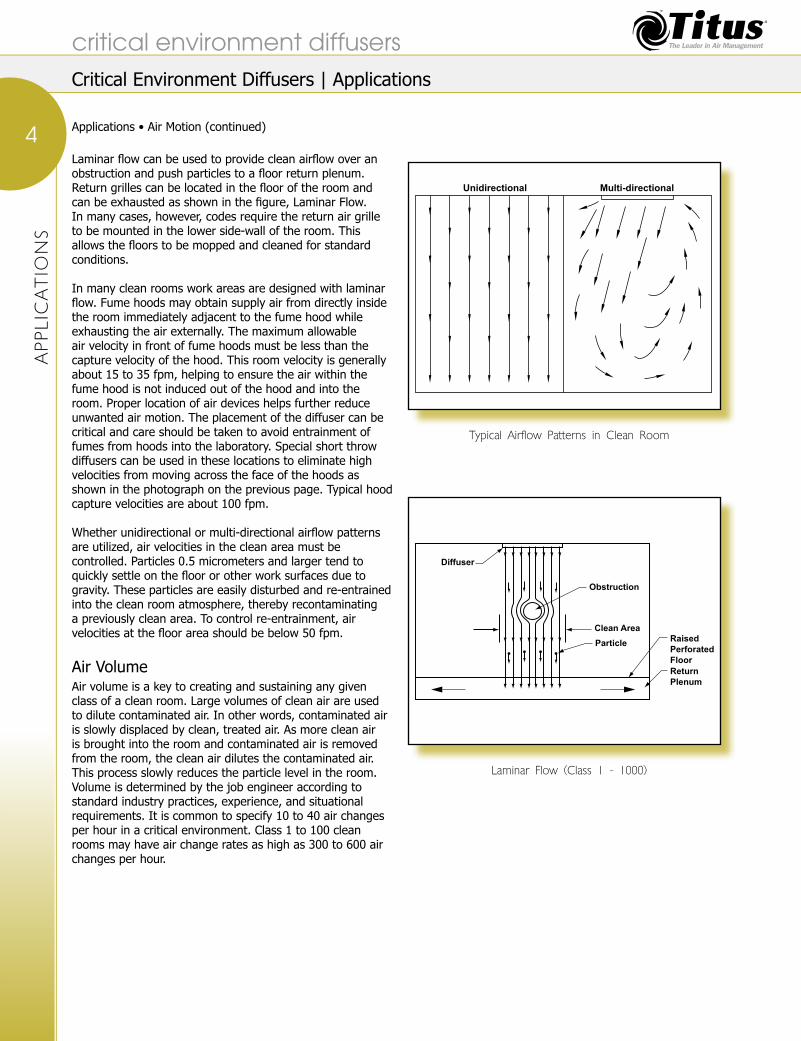
Air MotionMotion is critical to control concentrations of particles inthe entire clean room or in a particular area of the room.Air motion is either unidirectional, also called laminar, ormulti-directional. The following figure shows typical cleanroom airflow patterns. Unidirectional air motion is used topush unwanted particles out of the controlled space. Multi-directional air motion can be used to remove unwantedparticles by dilution.
When using multi-directional air motion the designeris depending solely on dilution to achieve the desiredcleanliness level. Although dilution may reduce particlelevels in the entire room to a moderate average level, it does not ensure that any given area in the room is controlled to acceptable particulate levels.
Sterile Environment Diffusers
Short-Throw Diffusers with Exhaust Hoods
FlowBar Diffusers | Hard Ceiling Applications
HEPA Filter ...................................................................................................................................................44
Application Notes ...........................................................................................................................................46Titus Operating Room Air Distribution System ..................................................................................................46Operating Room Air Distribution System .........................................................................................................47
Critical Environment Diffusers Overview
critical environment diffusers
3
Critical Environment Diffusers | Overview
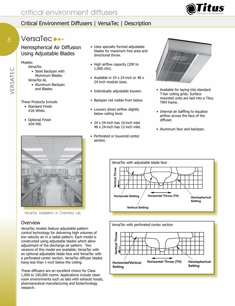
Laminar flow can be used to provide clean airflow over an obstruction and push particles to a floor return plenum. Return grilles can be located in the floor of the room and can be exhausted as shown in the figure, Laminar Flow. In many cases, however, codes require the return air grille to be mounted in the lower side-wall of the room. This allows the floors to be mopped and cleaned for standard conditions.
In many clean rooms work areas are designed with laminar flow. Fume hoods may obtain supply air from directly inside the room immediately adjacent to the fume hood while exhausting the air externally. The maximum allowable air velocity in front of fume hoods must be less than the capture velocity of the hood. This room velocity is generally about 15 to 35 fpm, helping to ensure the air within the fume hood is not induced out of the hood and into the room. Proper location of air devices helps further reduce unwanted air motion. The placement of the diffuser can be critical and care should be taken to avoid entrainment of fumes from hoods into the laboratory. Special short throw diffusers can be used in these locations to eliminate high velocities from moving across the face of the hoods as shown in the photograph on the previous page. Typical hood capture velocities are about 100 fpm.
Whether unidirectional or multi-directional airflow patterns are utilized, air velocities in the clean area must be controlled. Particles 0.5 micrometers and larger tend to quickly settle on the floor or other work surfaces due to gravity. These particles are easily disturbed and re-entrained into the clean room atmosphere, thereby recontaminating a previously clean area. To control re-entrainment, air velocities at the floor area should be below 50 fpm.
Air Volume Air volume is a key to creating and sustaining any given class of a clean room. Large volumes of clean air are used to dilute contaminated air. In other words, contaminated air is slowly displaced by clean, treated air. As more clean air is brought into the room and contaminated air is removed from the room, the clean air dilutes the contaminated air. This process slowly reduces the particle level in the room. Volume is determined by the job engineer according to standard industry practices, experience, and situational requirements. It is common to specify 10 to 40 air changes per hour in a critical environment. Class 1 to 100 clean rooms may have air change rates as high as 300 to 600 air changes per hour.
Typical Airflow Patterns in Clean Room
Laminar Flow (Class 1 - 1000)
APPLICATIO
NS
Applications • Air Motion (continued)
critical environment diffusers
4
Unidirectional Multi-directional
Diffuser
Obstruction
Clean Area
ParticleRaised
Perforated
Floor
Return
Plenum
Critical Environment Diffusers | Applications

Air Filtration and Quality Control All clean rooms utilize filtration systems to purify incoming air and/or recirculated air. These systems usually include prefilters that are low cost and easily replaceable. Prefilters are the first step in extracting or trapping unwanted particles from the air.
Upstream of the high-efficiency particulate (HEPA) or ultra-low penetration (ULPA) air filters, prefilters of 30 percent and then 85 percent greatly reduce the amount of contaminants that need to be eliminated by HEPA or ULPA filters. The chart on this page classifies commonly designated filters and their efficiencies.
For clean room classes 1,000 to 100,000, regardless of the filter classification specified, several principles should be considered prior to application. The best place for high-efficiency filters is upstream of the air outlets in a remote location. If the high-efficiency filter is an integral part of the air distribution device, removal of the filter should be accomplished from outside the protected zone. Working with the filter in the protected zone creates a high probability of contaminating the clean zone.
Volume control dampers should be located upstream of the high-efficiency filter so that operation of the damper does not contaminate the airstream.
Chemical filtration may also be included. The filter media is typically activated carbon.
Air quality includes temperature and humidity control. Elaborate systems have been developed by the industry to control these two factors. Humidity is typically controlled somewhere around 50%. Temperature control specifications may be within 1° F or less.
Pressurization of the clean room or clean zone also contributes to air quality. Higher pressure clean zones help reduce infiltration of contaminants from outside
sources. The typical room differential pressure specified is 0.05 inch wg according to Federal Standard 209B. Most critical environmental rooms have positive pressurization to keep contamination out of these areas.
Proper Equipment Equipment and construction materials may emit contamination. Equipment utilized in clean rooms is typically 304 stainless steel. Internal construction is engineered to retard outflow of contaminants from sources such as bearings, plastics and other decaying material or moving parts.
Air showers or tunnels may be provided for personnel entering the controlled zone. Air curtains may be used to also protect the clean zone.
Cleaning equipment such as high efficiency vacuum cleaners, tack cloths, lint-free cleaning cloths and autoclaves all contribute to the overall cleanliness of the room or area.
Personnel TrainingProper clean room etiquette is critical to maintaining a clean environment. Protocol for entering the room and leaving the room must be maintained. Movement within the room must be controlled. Sudden movements by personnel can entrain settled contaminated particles back into the clean airstream.
Titus has a complete line of diffusers designed for applications requiring unidirectional or multi-directional airflow. Laboratories, operating rooms, electronics manufacturing, pharmaceutical and biotechnology manufacturing, automotive painting and many other applications can benefit from using Titus Critical Environment Diffusers.
Name Designation Efficiency Max Particle Size
High-Efficiency Filter HE 95% 0.3µ
High-Efficiency Particulate Filter HEPA 99.90% 0.3µ
Ultra-Low Penetration
Air FilterULPA 99.9995% 0.12µ
Filter Designation and Efficiency Level
APPLIC
ATIO
NS
Applications (continued)
critical environment diffusers
5
Critical Environment Diffusers | Applications
Hemispherical Air Diffusion Using Adjustable Blades Models: VersaTec
Steel Backpan with • Aluminum Blades.
VersaTec-AL Aluminum Backpan • and Blades.
These Products IncludeStandard Finish • #26 White.
Optional Finish • #04 Mill.
Uses specially formed adjustable • blades for maximum free area and directional throw.
High airflow capacity (200 to • 1,000 cfm).
Available in 24 x 24-inch or 48 x • 24-inch module sizes.
Individually adjustable louvers.•
Backpan not visible from below. •
Louvers direct airflow slightly • below ceiling level.
24 x 24-inch has 10-inch inlet • 48 x 24-inch has 12-inch inlet.
Perforated or louvered center • section.
Available for laying into standard • T-bar ceiling grids. Surface mounted units are laid into a Titus TRM frame.
Internal air baffling to equalize • airflow across the face of the diffuser.
Aluminum face and backpan.•
VersaTec Installation in Chemistry Lab
VERSATEC
VersaTec
critical environment diffusers
6
VersaTec with adjustable blade face
VersaTec with perforated center section
Ve
rti
ca
l T
hro
w
Horizontal Throw (TH)Hemispherical
Setting
Horizontal Setting
Vertical Setting
Ve
rti
ca
l T
hro
w
Horizontal Throw (TH) Hemispherical
Setting
Horizontal/Vertical
Setting
Critical Environment Diffusers | VersaTec | Description
OverviewVersaTec models feature adjustable pattern control technology for delivering high volumes of low velocity air in a radial pattern. Each model is constructed using adjustable blades which allow adjustment of the discharge air pattern. Two versions of this model are available; VersaTec with an optional adjustable blade face and VersaTec with a perforated center section. VersaTec diffuser blades hang less than 1-inch below the ceiling.
These diffusers are an excellent choice for Class 1,000 to 100,000 rooms. Applications include clean room environments such as labs with exhaust hoods, pharmaceutical manufacturing and biotechnology research.

DIM
ENSIO
NS
Dimensions
critical environment diffusers
7
VersaTec with perforated center section
InletSide View
Face View End View
Module minus ¼"
D m
inu
s 1
/8"
Mo
du
le m
inu
s ¼
"
3/8"
3/8"
6"
2"
VersaTec with optional adjustable blade face
Inlet
⅜"
⅜"6"
2"
D minus ⅛"
Module minus ¼"
Mod
ule
min
us ¼
"
Side View
Face View End View
Critical Environment Diffusers | VersaTec | Dimensions

PERFO
RMANCE DATA
Throws are to terminal velocities of 100, 50 and • 25 fpm. See the section, Engineering Guidelines and the topic Procedure to Obtain Catalog Throw Data in this catalog for throw information.
Use above performance data table for • optional curved blade center section.
NC is the noise criteria curve that will not • be exceeded in octave bands 2 thru 7. The NC assumes a 10 db room absorption.
Air patterns between the two shown in the • isovel diagrams on the previous page can be obtained by adjustment of the blades.
Discharge PatternHemispherical Horizontal
48”
x 24
” 12
” In
let
cfm 400 600 800 400 600 800NC 23 28 30 26 31 33
Total Pressure 0.05 0.10 0.18 0.05 0.13 0.24
5 F∆T Horizontal Throw 1-2-4 2-3-6 3-4-7 3-4-7 5-6-8 5-6-13Vertical Throw 1-2-3 2-3-5 2-4-7 1-3-4 2-3-6 3-4-7
15 F∆T Horizontal Throw 1-2-3 2-3-5 3-3-6 3-4-5 4-5-6 5-5-11Vertical Throw 1-3-5 2-4-7 2-4-8 1-3-6 2-4-8 3-5-9
24”
x 24
”
10”
Inle
t
cfm 200 300 400 200 300 400NC 21 25 27 22 27 29
Total Pressure 0.02 0.07 0.14 0.04 0.09 0.16
5 F∆T Horizontal Throw 1-1-1 1-1-2 1-2-3 2-4-6 4-5-9 5-7-12Vertical Throw 1-1-2 1-2-4 2-3-5 2-3-6 3-5-7 4-6-9
15 F∆T Horizontal Throw 1-1-1 1-1-2 1-1-2 2-3-5 2-4-8 5-6-10Vertical Throw 1-1-3 1-2-5 2-4-6 2-3-8 3-5-8 4-7-10
Performance DataVersaTec and VersaTec-AL
critical environment diffusers
8
Critical Environment Diffusers | VersaTec | Performance Data

SPECIFIC
ATIO
NS
VersaTec, VersaTec-ALAir diffusers marked _______ shall be Titus model number VersaTec, VersaTec-AL. Diffusers shall be constructed using a maximum 6 inches tall backpan designed for optimum performance with the diffuser.
The backpan shall be provided with cross sectionalizing baffles to evenly distribute supply air. The diffuser face shall have adjustable longitudinal extruded aluminum blades for directional air control. The face shall hang below ceiling level no more than 1¼ inches when the blades are in the full open position. Blades shall be divided into three sets: right-hand, left-hand and vertical projection.
The air pattern must be adjustable from a radial pattern to a horizontal, vertical, or a combination of both horizontal and vertical. Diffuser shall be available with optional 51 percent free area perforated center section.
PerformanceNC values representing the noise criteria curve shall be published. Throw values for terminal velocities of 100, 50 and 25 fpm shall be published along with corresponding pressure drop.
Throws shall be published for both horizontal and vertical air patterns. Performance tests shall have been conducted in accordance with ASHRAE Standards 70-2006 and 113.
Model Module Size Optional FinishVersaTec-AL 24 x 24 Rapid Mount TRM White (std.) 26
VersaTec 48 x 24 Frame Mill 04
XXXXXXX-XX XX XX x XX X XX XX XX
Inlet Size Blow Pattern Face Style48 x 24 Module 12” 12 2-Way 2 Perforated Center P24 x 24 Module 10” 10 Straight Blade S
Model Number Specification
Suggested Specifications
critical environment diffusers
9
Critical Environment Diffusers | VersaTec | Specifications

High Volume, Low Velocity, Radial Air Diffusion Technology Models: TriTec
Steel Face and Back Pan• TriTec-AL
304 Stainless Steel Face • with Aluminum Back Pan.
TriTec-SS304 Stainless Steel • Face and Back Pan.
These Products IncludeStandard Finish • #26 White. Optional Finish • #04 Mill.
Face drops no more than ⅝-inch • below the ceiling.
Removable face for sanitizing (no • special tool required to remove the face).
Available in steel, 304 stainless • steel, or aluminum with 304 stainless steel face.
Available in 24 x 24-inch and 48 x • 24-inch module sizes.
Low velocity hemispherical pattern • or one-way hemispherical pattern available.
Factory supplied back pan with • every unit.
22-gauge backpan. •
Available in inlet sizes of 8 or 10 • inches for 24 x 24-inch module sizes, 10 or 12 inches for 24 x 48-inch module sizes.
Standard unit lays into standard • T-bar ceiling grids. Optional TRM mounting frame available for surface mounting.
Simple to install and maintain. •
Great for use in fume hood areas. •
Earthquake tabs supplied as • standard.
Retainer cable supplied with every • unit.
51 percent free area perforated • face matches industry standard perforated diffuser’s appearance.
Chemistry Lab with TriTec Diffusers
TRITEC
critical environment diffusers
10
TriTec Laboratory Application - Side View
TriTec Laboratory Application - Plan ViewTriTec Laboratory Application - End View
Critical Environment Diffusers | TriTec | Description
TriTec

DIM
ENSIO
NS
OverviewTriTec models are designed to allow large volumes of air to be brought into the environment with very short throws.
Discharging air flow patterns of a two-way blow provide a 180 degree radial pattern, TriTec takes advantage of the maximum space available for distributing velocity. This results in the lowest possible velocities for the volume of air being delivered. Unlike competitive models, TriTec takes advantage of a 51 percent free area perforated face that hangs below the ceiling less than ⅝-inch. In appearance, TriTec models look like industry standard perforated diffusers.
TriTec’s unique design allows it to create a full pattern in the middle of the diffuser as well as on the ends. The design of the TriTec allows these diffusers to be mounted end to end without increasing the throw.
Applications include labs with exhaust fans, pharmaceutical manufacturing, telephone switching rooms, biotechnology research and many other applications where high airflows with short throws are required. This diffuser has a very high induction rate. These diffusers are an excellent choice for Classes 1,000 to 100,000 rooms.
High induction diffusers, like the TriTec should not be specified for operating rooms.
DimensionsAir enters the diffuser and is spread across the entire diffuser by the pressure induction plate. As air passes through the pressure induction plate it expands into the air dampening chamber. While passing through the air dampening chamber, long fixed blades direct the air creating a hemispherical air pattern as the air passes through the 51 percent free area face.
critical environment diffusers
11TriTec Layout
TriTec Lay-In Application
Surface Mount Application with Optional TRM Rapid Mount Frame
Top View
Side View
End ViewModule size minus ¼"
Module Size
Safety Chain
Earthquake TabsPressureInductionPanel
PatternControllersVelocityDampeningChamberAirDampeningChamber
D minus⅛"
⅝" to 11/16" (Typ.)
2"
6"
Mod
ule
Siz
e m
inus
¼"
Module Size
Back pan
DiffuserFace
T-Bar
15/16"
Module Size
B C
Clip is adjustableup and down to fitvarying ceilingthickness
Back pan
DiffuserFace
1⅛" 3/16"½" to ⅞"
Critical Environment Diffusers | TriTec | Dimensions

PERFO
RMANCE DATA
Performance DataTriTec, TriTec-AL and TriTec-SS
Spread is the maximum width of the isovel • at the indicated terminal velocity.Vertical throw is the furthest distance below the ceiling • where the indicated terminal velocity can be measured.Tests were conducted in a 16 x 16-foot room, with • a 9-foot ceiling, low side wall returns, in accordance with ASHRAE Standard 113, in several planes.
Low emissivity heaters were used to maintain loads, • and were set to match the supply air conditions. The room was free of obstructions during the tests.Sound and pressure drop tests were • conducted in accordance with ASHRAE.Standard 70-2006 and ANSI S1.31 Procedures.•
Module Size Spread Vertical Throw (ft)and 2-Way Pattern (ft) 5 Deg ∆T 10 Deg ∆T 15 Deg ∆T
Inlet Size cfm Ps Pt Nc 100-75-50 100-75-50 100-75-50 100-75-50250 0.055 0.087 25 1 2 5 1 2 3 1 2 3 1 2 4
24” X 24” 300 0.080 0.126 29 2 3 6 1 3 4 1 2 4 2 3 58” Inlet 400 0.142 0.224 37 3 5 7 3 3 5 2 4 5 3 5 7
500 0.222 0.350 42 5 6 8 3 4 5 3 5 7 4 6 8250 0.026 0.039 <20 1 1 3 0 1 2 0 1 2 1 1 2
24” X 24” 300 0.037 0.056 20 1 2 4 1 1 2 1 1 3 1 1 310” Inlet 475 0.093 0.140 31 3 5 7 1 3 6 2 3 6 2 4 7
600 0.148 0.224 37 4 6 9 2 4 8 3 5 8 3 6 9375 0.054 0.084 <20 3 4 6 0 1 1 1 1 2 1 1 2
24” X 48” 500 0.097 0.149 26 4 6 9 1 1 3 1 2 4 1 2 410” Inlet 700 0.190 0.292 39 6 8 10 1 2 5 2 4 6 2 4 7
900 0.313 0.483 48 8 10 12 2 4 7 3 5 8 3 6 9500 0.054 0.080 20 1 2 4 1 1 2 1 1 3 1 2 4
24” X 48” 650 0.092 0.135 24 2 3 7 1 2 4 1 2 5 2 3 612” Inlet 750 0.122 0.179 34 2 4 9 1 2 5 2 3 6 2 4 7
1000 0.218 0.319 44 4 7 11 2 4 6 3 5 8 4 6 9Module Size Spread Vertical Throw (ft)
and 1-Way Pattern (ft) 5 Deg ∆T 10 Deg ∆T 15 Deg ∆TInlet Size cfm Ps Pt NC 100-75-50 100-75-50 100-75-50 100-75-50
250 0.055 0.087 <20 1 2 3 0 0 1 1 1 2 1 1 324” X 24” 325 0.094 0.148 29 2 3 4 0 1 2 1 2 4 1 2 58” Inlet 400 0.142 0.224 35 3 3 4 1 1 3 2 3 6 2 4 8
450 0.179 0.283 38 3 4 4 1 1 3 2 3 9 3 5 9250 0.025 0.038 <20 1 2 4 1 1 3 1 1 3 2 3 7
24” X 24” 350 0.049 0.075 22 3 4 6 1 2 5 2 3 6 4 6 910” Inlet 450 0.081 0.123 28 4 5 7 2 4 6 3 5 7 6 8 9
550 0.121 0.184 34 4 6 8 3 5 7 4 6 9 7 9 9500 0.092 0.144 24 1 2 3 1 2 4 1 2 4 3 6 9
24” X 48” 625 0.143 0.225 32 2 2 4 2 3 5 2 3 6 5 8 910” Inlet 750 0.206 0.324 39 2 3 4 2 4 6 2 4 7 7 9 9
900 0.297 0.467 44 3 4 6 4 5 8 4 7 9 8 9 9500 0.051 0.076 <20 1 2 3 2 4 7 4 6 8 4 6 8
24” X 48” 650 0.086 0.129 25 2 3 4 4 6 9 6 7 9 6 7 912” Inlet 750 0.114 0.171 31 3 3 5 5 7 9 6 8 9 6 8 9
1000 0.203 0.304 42 3 5 7 7 9 9 8 9 9 8 9 9
critical environment diffusers
12
End ViewDiffuser
Spread (ft)
100, 75 or 50 fpm Isovel
Ver
tical
Thro
w (f
t)
Critical Environment Diffusers | TriTec | Performance Data

SPECIFIC
ATIO
NS
TriTec
Air diffusers marked _______ shall be Titus model number TriTec. Diffusers shall be constructed using a maximum 6 inches tall backpan designed for optimum performance with the diffuser. The backpan shall be divided into two chambers: upper and lower. The backpan shall have integral hanger tabs for securing the unit to the overhead structure. The upper velocity dampening chamber shall be separated from the lower air dampening chamber by a pressure induction plate. All pattern controllers shall be internal to the unit and shall be located in the lower air dampening chamber.
The face of the diffuser shall be 51 percent free area perforated steel with 3/16-inch diameter holes on ¼-inch staggered centers, and shall match the appearance of industry standard perforated diffusers. The face shall not hang below the ceiling more than ⅝ inches and shall have 6 clips securing it in place. Quarter-turn fasteners on the face are not acceptable. The face, lower air chamber, directional blades, and the pressure induction plate shall be one assembly that can be removed from the face of the unit for sanitizing in an autoclave. The face shall be provided with two retainer cables.
The backpan shall be manufactured of 22-gauge steel. The diffuser must be available for full radial air diffusion (two-way) and/or ½ radial air diffusion (one-way).
Performance
NC values shall be published. Throw for terminal velocities of 100, 75 and 50 fpm shall be published along with corresponding pressure drop. See the section, Engineering Guidelines and the topic ‘Procedure to Obtain Catalog Throw Data’ for additional throw data.
Performance tests shall have been conducted in ASHRAE Standards 70-2006 and 113.
TriTec-ALUse TriTec specification and make the following changes:
Change the model number to TriTec-AL. •
Change the reference of steel to aluminum for the • backpan.
Change the reference of steel to 304 stainless steel for • the face.
TriTec-SSUse TriTec specification and make the following changes:
Change the model number to TriTec-SS. •
Change all reference of steel to 304 stainless steel.•
Model Number Specification
ModelTriTec Module Size Finish
TriTec-AL 24 x 48 White (std.) 26
TriTec-SS 24 x 24 Mill 4
XXXXXX-XX XX XXxXX X XX TRM
Inlet Size Blow Pattern(note) 8” 8 1-Way 1 Optional
10” 10 2-Way 2 Rapid Mount12” 12 Frame
Note: 8 and 10-inch inlets available with 24 x 24 module; 10 and 12-inch inlets available with 24 x 48 module.
Suggested Specifications
critical environment diffusers
13
Critical Environment Diffusers | TriTec | Specifications

TLF
Vertical Laminar Flow Technology Models: TLF
Steel • TLF-AA
Aluminum• TLF-SS
304 Stainless Steel•
These Products IncludeStandard Finish • #26 White.Optional Finish • #04 Mill.
Ideal for installation in hospital operating rooms. •
Center plug removes from face for access to • screwdriver slot for damper adjustment.
Perforated face quickly • removes by loosening quarter-turn fasteners.
Retainer cables prevent the perforated face from falling • after removal.
Internal baffles to distribute air • evenly over perforated face.Perforated face with • 3/32-inch diameter holes on ¼-inch centers in a 60° staggered pattern.
Compatible with 1-inch or • 1½-inch T-bar ceiling grids.
Optional TRM mounting frame • available for surface mounting.
Optional HEPA filter rack on TLF-AA and • TLF-SS. (Filter by Titus or others)
Available in steel, aluminum • or 304 stainless steel.
TLF
critical environment diffusers
14
Ceiling Module Size C (Lay-In Applications)
C minus 3"
1¼"C minus 1⅜"
Cי minus 1⅜"
Cי minus ¼"
C minus ¼"
5⅝"
⅜"
Removable Center PlugFor Screwdriver Access
Retainer Cable
Dminus ⅛"
D
Screwdriver SlotDeflector Ring
B
Ceiling Opening = Module Size minus 1" (Surface Mount Applications)
Ceiling Opening = Module Size C minus 1" (Surface Mount Applications)
¼-TurnFastener
Inlet Height
D
Neck Size B
6, 7, 8 2”
10, 12 2”
Critical Environment Diffusers | TLF | Description

TLF laminar flow diffusers are the industry standard for unidirectional flow. When unidirectional flow is desired, typically in areas classified as 1 to 1000, TLF is the choice.
TLF diffusers can be used to create clean zones by positioning the diffuser directly over the area to be washed with clean air. Clean zones are typically used as process areas within a clean room.
TLF diffusers are also used in most operating rooms as the center diffuser and many times these diffusers are surrounded by a linear air curtain. The vertical piston of air created by the TLF is used to discharge clean air over the patient during operations.
Laminar flow minimizes air induction, reducing the opportunity for contaminated air to be re-entrained and pollute a clean airstream.
The TLF Series of laminar flow diffusers generates a low velocity, evenly distributed, downward moving “piston” of conditioned air.
Installed over the operating table in a hospital operating room, TLF diffusers help protect the patient from contaminated room secondary air. The only appreciable amount of room air entrainment occurs at the boundaries of the moving air mass, outside the confines of the operating table. As a result, the patient is effectively isolated from residual room air.
TLF is especially effective in cooling areas with heavy, localized, internal loads, as in computer rooms. The column of air delivered by the TLF cools the load source directly without generating high velocities in the occupied space.
HEPA Filter OptionThe Air Diffusers marked _______ shall be Titus Model (TLF-SS) (TLF-AA) – HEPA. The diffusers shall be constructed using a 9 inch tall back pan HEPA filter mounting rock and knife edge. The filter, by Titus or others, shall have a Gel Seal that the knife edge fits into. The filter shall be held in place using four #10-24 wing nuts.
Module Size (inches)
Edge Dimensions of HEPA Rack (inches)
Length Width
24 x 24 17⅜17⅜
36 x 24 29⅜
48 x 12
41⅜
5⅜
48 x 24 17⅜
48 x 36 29⅜
60 x 24 53⅜ 17⅜
72 x 1265⅜
5⅜
72 x 24 17⅜
TLF
Overview
critical environment diffusers
15
TLF-AA/TLF-SS HEPA Filter Dimensions and Mounting Details
SECTIONAL VIEW
HEPA Filter to be furnishedand installed by others
HEPAFilter
Wing Nut
FilterHoldingClip
HEPA FilterGel Seal(by others)
9½"
213/16"
3"
Inlet Ring
HEPA Rack
Knife Edge Dimensionof HEPA RackLength x Width
HEPA Filter Rack
Critical Environment Diffusers | TLF | Description

PERFO
RMANCE DATA
Performance DataTLF, TLF-AA and TLF-SS
All data based on full open damper position.• NC values are based on a room absorption of 10 dB.• Data obtained in accordance with • ASHRAE 70-2006 and 113.Throw is based on 0-5• cooling with terminal velocities of 75, 50 and 30 fpm.
Performance data does not include • pressure loss of optional HEPA filter.See the section, Engineering Guidelines and • the topic ‘Procedure to Obtain Catalog Throw Data’ in this catalog for throw information.
7” Round Neck Airflow, cfm 100 120 140 160 180 220 240 260 300 Total Pressure 0.042 0.060 0.082 0.110 0.135 0.200 0.240 0.280 0.370
48” x 12” Face NC (Noise Criteria) 11 17 22 26 29 35 38 41 45Vert. Projection 1-2-3 1-3-4 2-4-5 2-4-6 3-5-7 4-7-8 5-7-9 6-8-10 6-9-11
Total Pressure 0.039 0.056 0.076 0.100 0.125 0.195 0.223 0.260 0.34860” x 12” Face NC (Noise Criteria) - 16 21 25 28 34 37 40 44
Vert. Projection 1-2-3 1-3-4 2-4-5 2-4-6 3-5-7 4-7-8 5-7-9 6-8-10 6-9-10 Total Pressure 0.036 0.053 0.071 0.094 0.116 0.180 0.210 0.245 0.320
72” x 12” Face NC (Noise Criteria) - 15 20 24 27 33 36 39 43Vert. Projection 1-2-3 1-3-4 2-4-5 2-4-6 3-5-7 4-7-8 5-7-9 6-8-10 6-9-10
7” Round Neck Airflow, cfm 100 120 140 160 180 220 240 260 300 Total Pressure 0.042 0.060 0.082 0.110 0.135 0.200 0.240 0.280 0.370
24” x 24” Face NC (Noise Criteria) 11 17 22 26 29 35 38 41 45Vert. Projection 1-2-3 1-3-4 2-4-5 2-4-6 3-5-7 4-7-8 5-7-9 6-8-10 6-9-12
Total Pressure 0.036 0.053 0.071 0.094 0.116 0.180 0.210 0.245 0.32036” x 24” Face NC (Noise Criteria) - 16 21 25 28 34 37 40 44
Vert. Projection 1-2-3 1-3-4 2-4-5 2-4-6 3-5-7 3-6-8 4-6-9 5-7-10 5-8-10 Total Pressure 0.033 0.047 0.065 0.087 0.107 0.160 0.190 0.223 0.290
48” x 24” Face NC (Noise Criteria) - 15 20 24 27 33 36 39 43Vert. Projection 1-1-3 1-3-4 2-4-5 2-4-6 2-5-7 3-6-8 4-6-9 5-7-10 5-8-10
8” Round Neck Airflow, cfm 100 120 140 160 180 220 240 260 300 Total Pressure 0.020 0.027 0.038 0.050 0.062 0.090 0.113 0.130 0.175
48” x 24” Face NC (Noise Criteria) - - 14 18 22 28 31 33 37Vert. Projection 1-1-3 1-2-4 1-3-5 2-4-6 2-5-7 3-6-8 3-6-9 4-7-10 5-8-10
Total Pressure 0.020 0.027 0.038 0.049 0.061 0.089 0.109 0.126 0.16860” x 24” Face NC (Noise Criteria) - - 14 18 22 28 31 33 37
Vert. Projection 1-1-3 1-2-3 1-3-5 2-4-6 2-5-7 3-6-8 3-6-9 4-7-10 5-8-10 Total Pressure 0.019 0.027 0.037 0.048 0.060 0.088 0.105 0.124 0.162
72” x 24” Face NC (Noise Criteria) - - 14 18 22 28 31 33 37Vert. Projection 1-1-3 1-2-3 1-3-5 2-4-6 2-5-6 3-6-8 3-6-9 4-7-10 5-8-10
10” Round Neck Airflow, cfm 215 240 265 295 320 345 400 425 515 Total Pressure 0.043 0.053 0.065 0.080 0.094 0.110 0.147 0.166 0.244
48” x 24” Face NC (Noise Criteria) 19 22 25 28 31 33 38 40 45Vert. Projection 2-5-6 2-6-7 3-6-8 4-7-9 5-8-9 5-8-10 6-9-11 7-10-12 9-12-14
Total Pressure 0.043 0.053 0.065 0.080 0.094 0.110 0.147 0.16 0.24460” x 24” Face NC (Noise Criteria) 19 22 25 28 31 33 38 40 45
Vert. Projection 2-5-6 2-6-7 3-6-8 4-7-9 5-8-9 5-8-10 6-9-11 7-10-12 9-12-14 Total Pressure 0.042 0.052 0.063 0.079 0.092 0.107 0.145 0.163 0.240
72” x 24” Face NC (Noise Criteria) 19 22 25 28 31 33 38 40 45Vert. Projection 2-4-5 2-5-6 3-5-7 4-6-8 5-7-9 5-7-9 5-8-10 6-9-11 8-11-13
12” Round Neck Airflow, cfm 215 240 265 295 320 345 400 425 515 Total Pressure 0.023 0.029 0.035 0.043 0.051 0.059 0.080 0.090 0.132
48” x 24” Face NC (Noise Criteria) 11 15 18 22 24 27 32 34 40Vert. Projection 2-5-6 2-6-7 3-6-8 4-7-9 5-8-9 5-8-10 6-9-11 7-10-12 9-12-14
Total Pressure 0.023 0.029 0.035 0.043 0.051 0.059 0.080 0.090 0.13260” x 24” Face NC (Noise Criteria) 11 15 18 22 24 27 32 34 40
Vert. Projection 2-5-6 2-6-7 3-6-8 4-7-9 5-8-9 5-8-10 6-9-11 7-10-12 9-12-14 Total Pressure 0.023 0.028 0.034 0.042 0.050 0.058 0.078 0.088 0.129
72” x 24” Face NC (Noise Criteria) 11 15 18 22 24 27 32 34 40Vert. Projection 2-4-5 2-5-6 3-5-7 4-6-8 5-7-8 5-7-9 5-8-10 6-9-11 8-11-15
critical environment diffusers
16
Critical Environment Diffusers | TLF | Performance Data

SPECIFIC
ATIO
NS
PerformanceNC values shall be published. Throw for terminal velocities of 75, 50 and 30 fpm shall be published along with corresponding pressure drop.See the section, Engineering Guidelines and the topic Procedure to Obtain Catalog Throw Data in this catalog for catalog throw information. Performance tests shall have been conducted in ASHRAE Standards 70-2006 and 113.
TLFAir diffusers marked _______ shall be Titus model number TLF. Diffusers shall be constructed using a maximum 6 inches tall backpan designed for optimum performance with the diffuser. The backpan shall have integral hanger tabs for securing the unit to the overhead structure. Each unit shall have an integral internal baffle for evenly distributing air over the entire face of the diffuser. Each unit shall have an integral volume damper accessible through the face of the diffuser. The face of the diffuser shall be constructed of 22-gauge steel perforated with 3/32-inch diagmeter holes on ¼-inch centers. The free area of the face shall be 13 percent. The face shall be secured in place by quarter-turn fasteners for quick removal and sanitizing. Each unit must have a removable center plug for adjusting the damper.
TLF-AAAir diffusers marked _______ shall be Titus model number TLF-AA. Diffusers shall be constructed using a maximum 6 inches tall backpan designed for optimum performance with the diffuser. The backpan shall have integral hanger tabs for
securing the unit to the overhead structure to prevent falling in case of earthquakes or other ceiling damage. Each unit shall have an integral internal baffle for evenly distributing air over the entire face of the diffuser. Each unit shall have an integral volume damper accessible through the face of the diffuser. The face of the diffuser shall be constructed of 0.040-inch thick aluminum and shall be perforated with 3/32-inch diameter holes on ¼-inch centers. The free area of the face shall be 13 percent. The face shall be secured in place by quarter-turn fasteners for quick removal and sanitizing. Each unit must have a removable center plug for adjusting the damper.
TLF-SSAir diffusers marked _______ shall be Titus model number TLF-SS. Diffusers shall be constructed using a maximum 6 inches tall backpan designed for optimum performance with the diffuser. The backpan shall have integral hanger tabs for securing the unit to the overhead structure to prevent falling in case of earthquakes or other ceiling damage. Each unit shall have an integral internal baffle for evenly distributing air over the entire face of the diffuser. Each unit shall have an integral volume damper accessible through the face of the diffuser. The face of the diffuser shall be constructed of 22-gauge 304 stainless steel perforated with 3/32-inch diameter holes on ¼-inch centers. The free area of the face shall be 13 percent. The face shall be secured in place by quarter-turn fasteners for quick removal and sanitizing. Each unit must have a removable center plug for adjusting the damper.
Model Number Specification
Model Module Size MaterialTLF C” x C” Steel ST
TLF-AA See table below.
304 Stainless Steel SSTLF-SS Aluminum AA
XXX-XX XX XX x XX XXX XX XX
Inlet Size Accessories Finish(Round) 6” Earthquake Tabs EQT White (std.) 26
Note: For availability of inlet size by module size, see table below.
7” HEPA Filter Rack H Mill 048” (TLF-AA & TLF-SS only)
9”10”12”
C” x C” 24 x 12 24 x 24 36 x 12 36 x 24 48 x 12 48 x 24 48 x 36 60 x 12 60 x 24 60 x 36 72 x 12 72 x 24 72 x 36
D” 5, 6, 75, 6, 7, 8, 9, 10,
125, 6, 7
5, 6, 7, 8, 9, 10,
125, 6, 7
5, 6, 7, 8, 9, 10,
12
5, 6, 7, 8, 9, 10,
125, 6, 7
5, 6, 7, 8, 9, 10,
12
5, 6, 7, 8, 9, 10,
125, 6, 7
5, 6, 7, 8, 9, 10,
12
5, 6, 7, 8, 9, 10,
12
Available Nominal Ceiling Module Sizes C” x C” and Nominal Round Duct Sizes D”
Suggested Specifications
critical environment diffusers
17
Critical Environment Diffusers | TLF | Specifications

High Volume Low Velocity Radial Air Diffusion Technology Models: RadiaTec-AL
Aluminum Face and Backpan.• RadiaTec-SS
304 Stainless Steel Face and Backpan.•
These Products IncludeStandard Finish • #26 White. Optional Finish • #04 Mill.
Removable face for sanitizing from room-side (no • special tool required).
Available in aluminum and 304 stainless steel modular • parts, (face and back pan can be of a different material).
Available in 24 x 24-inch and 48 x 24-inch module sizes • with one-way or two-way patterns.
Available inlet sizes: 8 or 10 inches for 24 x 24-inch; 10 • or 12 inches for 48 x 24-inch modules.
Compatible with 1 or 1½-inch T-bar ceiling grids. • Optional TRM mounting frame available for surface mounting.
Optional HEPA Filter rack available.• (filter by Titus and others)
Unique baffling inside diffuser assures even air • distribution across entire face.
Quarter-turn fasteners and retainer cables allow easy • access for cleaning and filter replacement.
RADIATEC
OverviewThe RadiaTec diffuser is designed to meet the challenge of diluting airborne contaminants by supplying high- volume, low-velocity airflow to displace these impurities. The airflow pattern is designed to produce a uniform pattern to prevent dead spots where contaminants can linger. In addition, the air pattern is tighter to the ceiling than competitor models to limit the air pattern penetration into the habitable zone.
The RadiaTec creates a full pattern along the face of the diffuser, and when mounted end-to-end, throw is not increased.
Applications include labs with exhaust fans, pharmaceutical manufacturing, biotechnology and other applications where high air volume with short flow are required. The RadiaTec’s high induction rate draws impurities into its airstream, allowing it to be diluted to less harmful levels prior to exhausting the air. Excellent choice for Class 1,000 to 100,000 rooms.
RadiaTec
critical environment diffusers
18
RadiaTec in Laboratory Application - Side View
RadiaTec in Laboratory Application - Plan ViewRadiaTec in Laboratory Application - End View
Critical Environment Diffusers | RadiaTec | Description
DIM
ENSIO
NS
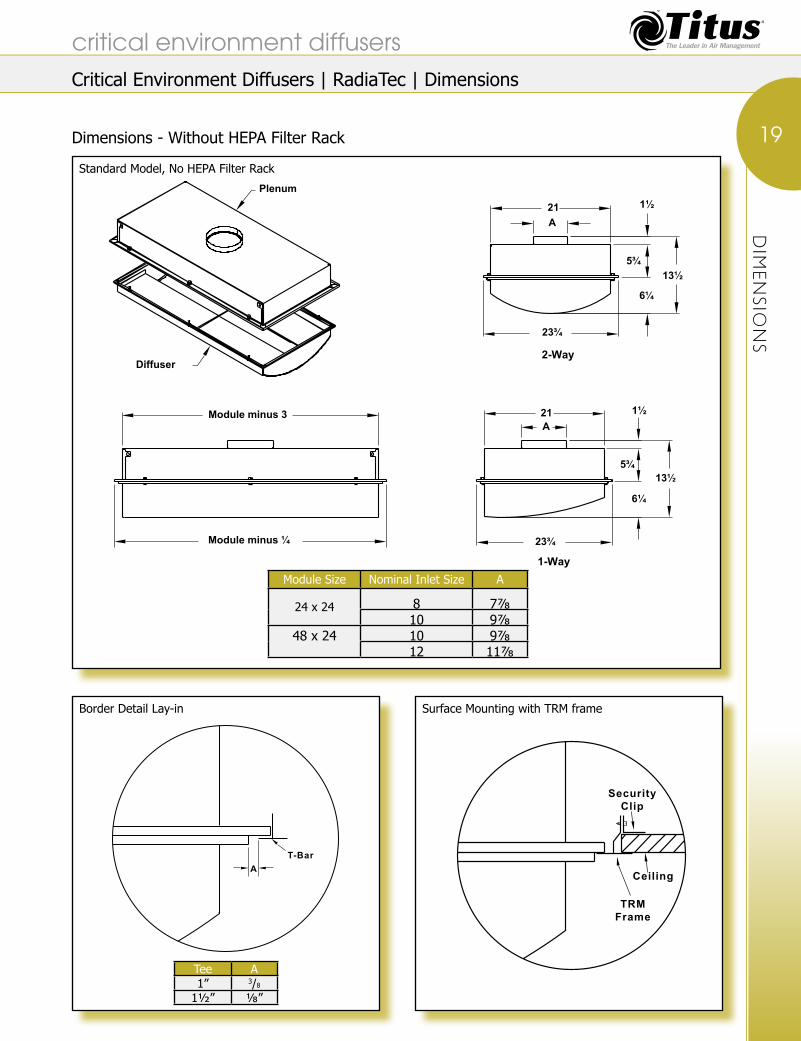
Dimensions - Without HEPA Filter Rack
critical environment diffusers
19Standard Model, No HEPA Filter Rack
Module Size Nominal Inlet Size A
24 x 24 8 7⅞10 9⅞
48 x 24 10 9⅞12 11⅞
Border Detail Lay-in
Tee A1” 3/8
1½” ⅛”
Surface Mounting with TRM frame
23¾
A21 1½
5¾
6¼
13½
1-Way
2-Way
Plenum
Module minus ¼
Module minus 3
5¾13½
6¼
1½21A
23¾
Diffuser
T-BarA
SecurityClip
Ceiling
TRMFrame
Critical Environment Diffusers | RadiaTec | Dimensions

DIM
ENSIO
NS
Dimensions - With HEPA Filter Rack
critical environment diffusers
20HEPA Filter Rack Model
HEPA Filter Rack Knife Edge Dimensions HEPA Filter Rack
Plenum
Diffuser
16½
6¼
8¾
1½21
A
23¾
16½8¾
1½21A
23¾
6¼
Module minus ¼
A
Module minus 3
1-Way
2-Way
Module Size minus 6⅝
Module Size Nominal Inlet Size A
24 x 24 8 7⅞10 9⅞
48 x 24 10 9⅞12 11⅞
HEPA Filter Gel Seal (by Others)
HEPA Filter
Filter Holding Clip
Knife Edge
Wing Nut
Interior Edge Sealed
Critical Environment Diffusers | RadiaTec | Dimensions

PERFO
RMANCE DATA
Performance DataRadiaTec-AL and RadiaTec-SS
Spread is the maximum width of the isovel • at the indicated terminal velocity.Horizontal throw is the furthest distance from • diffuser center point where the indicated terminal velocity can be measured.Vertical throw is the furthest distance below the ceiling • where the indicated terminal velocity can be measured.
Low emissivity heaters were used to • maintain loads, which were set to match the supply air conditions. There were no obstructions in the room during the tests.Sound and pressure drop tests were conducted • in accordance with ASHRAE Standard 70-2006 and ANSI S1.31 Procedures.
Module Size Inlet Size
2-Way Pattern Horizontal Throw (feet) Vertical Throw (feet)5 Degree ∆T 15 Degree ∆T 5 Degree ∆T 15 Degree ∆T
cfm Ps Pt NC 100 - 75 - 50 100 - 75 - 50 100 - 75 - 50 100 - 75 - 50
24” x 24” 8” Inlet
200 0.082 0.061 - 5 6 8 4 5 7 2 3 3 2 3 4300 0.092 0.138 18 7 8 9 6 7 8 2 4 5 2 4 6400 0.163 0.245 28 8 9 10 7 8 10 4 5 6 4 5 7
24” x 24” 10” Inlet
300 0.075 0.094 18 6 7 8 6 6 7 3 4 5 3 4 5400 0.133 0.167 28 6 7 9 6 7 8 4 5 6 4 5 6500 0.209 0.261 35 7 8 10 7 8 9 4 5 6 5 6 7
48” x 24” 10” Inlet
400 0.027 0.061 - 2 3 5 2 3 5 1 2 3 2 3 4600 0.062 0.138 15 4 5 6 4 5 6 1 2 4 3 4 6800 0.111 0.245 23 5 6 7 5 6 7 1 2 4 4 5 7
48” x 24” 12” Inlet
600 0.065 0.101 - 4 5 7 3 5 6 2 3 4 3 4 5800 0.114 0.179 20 5 6 8 4 5 7 3 4 5 4 5 61000 0.179 0.280 27 6 7 9 5 6 8 3 4 6 4 5 7
Module Size Inlet Size
1-Way Pattern Horizontal Throw (feet) Vertical Throw (feet)5 Degree ∆T 15 Degree ∆T 5 Degree ∆T 15 Degree ∆T
cfm Ps Pt NC 100 - 75 - 50 100 - 75 - 50 100 - 75 - 50 100 - 75 - 50
24” x 24” 8” Inlet
200 0.053 0.071 12 5 6 7 5 6 7 1 2 3 1 2 3300 0.118 0.164 25 6 7 8 6 7 9 2 4 6 2 4 6400 0.209 0.291 34 7 8 9 7 8 10 4 5 7 3 5 7
24” x 24” 10” Inlet
300 0.111 0.130 26 5 6 7 5 6 8 4 5 6 6 7 9400 0.196 0.230 35 6 7 8 6 7 9 5 6 7 7 8 10500 0.308 0.360 41 7 8 10 7 8 10 6 7 8 8 9 11
48” x 24” 10” Inlet
400 0.029 0.063 - 3 5 7 3 5 8 3 4 6 4 6 8600 0.066 0.142 16 5 6 8 6 7 9 5 6 7 6 7 8800 0.119 0.253 26 7 8 9 7 8 10 5 6 8 7 8 10
48” x 24” 12” Inlet
600 0.075 0.111 - 4 6 8 5 6 7 4 5 6 6 6 7800 0.133 0.198 23 7 8 9 6 7 8 5 6 7 7 8 101000 0.208 0.309 31 8 9 11 7 8 9 5 6 7 8 9 11
critical environment diffusers
21
End View
Critical Environment Diffusers | RadiaTec | Performance Data

SPECIFIC
ATIO
NS
RadiaTecAir diffusers marked _______ shall be Titus model number RadiaTec-AL. Diffusers shall be constructed using a maximum 4 inches tall back pan (standard models) or 6-inch back pan (HEPA filter models) designed for optimum performance of the diffuser. The back pan shall be divided into two chambers connected via a baffle aperture designed to evenly distribute air across the diffuser’s perforated face. The back pan shall have integral hanger tabs for securing the unit to the overhead structure. The baffles forming the aperture will be located within the lower air chamber. The face of the diffuser shall be constructed of 13 percent free area perforated aluminum or ¼-inch staggard centers.
The interior of the diffuser shall be accessible for sanitization and filter replacement from below (room-side) by loosening the quarter-turn fasteners to allow the face to swing open, and can be disengaged by releasing the retainer cables attaching the face to the diffuser frame. The diffuser must by available for full radial air diffusion (two-way) or one-half radial air diffusion (one-way). The face and back pan will be constructed of aluminum, but will be modular to allow the face or back pan to be constructed of stainless steel, if required. Options include HEPA filter rack and foam gasketing.
PerformanceNC values shall be published. Throw for terminal velocities of 100, 75 and 50 fpm shall be published along with corresponding pressure drop. See the section, Engineering Guidelines and the topic ‘Procedure to Obtain Catalog Throw Data’ for additional throw information. Performance tests shall have been conducted in ASHRAE Standards 70-2006 and 113.
RadiaTec-SSUse RadiaTec specification and make the following changes:
Change the model number to RadiaTec-SS. • Change all reference of aluminum to 304 Stainless Steel.•
Model Number Specification
Blow Pattern
AccessoriesModel Module Size (Note1) (Note 2)
RadiaTec-AL 24 x 24 1-Way 1 HEPA Filter Rack HRadiaTec-SS 48 x 24 2-Way 2 Foam Gasketing FG
XXXXXXXX-XX XX XX x XX X XX XX
Inlet Size Finish8” 8 White (std. for
RadiaTec-AL)26
10” 1012” 12 Mill (std. for
RadiaTec-SS04
Note 1: 8 and 10-inch inlets available with 24 x 24 module; 10 and 12-inch inlets available with 48 x 24 module.
Note 2: Foam Gasketing is standard with HEPA Filter Rack option. Filter by Titus or others.
Specifications
critical environment diffusers
22
Critical Environment Diffusers | RadiaTec | Specifications

Linear Air Curtain Technology Vertical Air Curtain 2-Slot Diffuser for Perimeter Control of Pollutants Models: LineaTec-AL
Aluminum• LineaTec-SS
304 Stainless Steel•
These Products IncludeStandard Finish • #26 White Face (aluminum models).#04 Mill Finish • (304 stainless steel models and plenums).
LineaTec provides a curtain of • supply air.
Utilizes a free area slot with • an adjustable deflector for maximum efficiency and versatility.
Face available in 304 Stainless • Steel or aluminum.
Available in single sections up to 6 • inches long or multiple sections for continuous runs.
Available with optional 304 • Stainless Steel or aluminum plenums.
Plenums available with square • or round corners, quarter-turn fasteners for easy face removal and sanitizing.
Excellent for use as a perimeter air • curtain in clean air environments such as operating rooms.
May be used in surface mount • or lay-in applications.
OverviewLineaTec is a linear air curtain diffuser used to create an air curtain barrier between a clean zone and the balance of the room. The air curtain typically discharges 25 to 50 cfm per linear foot of slot. Flow rates of up to 100 cfm per linear foot of diffuser can be obtained with a two-slot LineaTec. LineaTec diffusers surround TLF diffusers in operating rooms to reduce internal contaminants in the operating theatre. With limited adjustable slots, the air curtain can be directed at a slight angle to facilitate balancing airflow in the entire operating theatre through directional control.
To meet sanitizing requirements, LineaTec diffusers are available with plenums that have optional corners radiused to ¾-inch. This allows easy manual cleaning of the inside of the plenum when the face is removed and reduces crevices where bacteria and other organisms can grow. Select LineaTec diffusers based on 50 fpm terminal velocity at knee height to 24 inches above floor - for most operating room applications.
Available Single Section LengthsLength Mounting
2’ Surface(1)3’ Surface(1)
3’6” Surface(1)4’ Surface(1)
4’6” Surface(1)5’ Surface(1)
5’6” Surface(1)6’ Surface(1)2’ T-bar Lay-In(2)3’ T-bar Lay-In(2)4’ T-bar Lay-In(2)
Note 1: May be used as T-bar lay-in by making the T-bar grid nominal unit LineaTec-SS: Length + 31/4 inches long by 151/4 inches wide. LineaTec-AL: Length + 31/16 inches long by 151/16 inches wide.
Note 2: Length fits in standard 2-, 3-, or 4-foot T-bar grid. Grid width must be 151/4 inches (151/16 inches for LineaTec-AL).
LineaTec
critical environment diffusers
23
LineaTec Diffuser Mounting Diagram
LineaTec-SS - Single Unit Construction - Face View
LineaTec-AL - Single Unit Construction - Face View
Surface Mounted T-Bar Lay-In
T-Bar(15/16" wide Tee)
Module Length
Hanger Wire
Hanger BracketCeilingTile Ceiling
Tile
Hanger Bracket
Hanger Wire
Note: Module Width for Lineatec - AL is 15 7/16," Liineatec - SS is 15¼"
Critical Environment Diffusers | LineaTec | Description
LINEATEC

DIM
ENSIO
NS
Dimensions Continuous Unit Construction
Connected with • aluminum joiner strips
Optional Plenum Construction
Available with corners • rounded (¾-inch radius) or with square corners.Bolted together in • the field.Hanger brackets • included.Square or rectangular • inlets available in 5-, 6- or 8-inch heights. For flange details see • page D23.
Available Section Lengths
(ft.)2’ 3’
3’6”4’
4’6” 5’
5’6” 6’
critical environment diffusers
24 LineaTec-AL - Continuous Unit Construction
LineaTec-SS - Continuous Unit Construction
Plenum Construction - Single Unit ConstructionNominal Length
½" Dia.1½"
1¾"
2"
12"
12"
Nominal Length
½" Dia.1½"
1¾"
2"
12"
12"
Rounded Corners Square Corners
Plenum Construction - Continuous Unit Construction
Overall Nominal Length plus 33/16"
Overall Nominal Length minus 6¾"
Overall Nominal Length
153/16"
AluminumJoiner Mullion
Nominal Length plus 119/32"
(Left section)
Nominal Length plus 119/32"
(Right section)
Nominal Length(Intermediate section)X Y X
12"
Y
Overall Nominal Length plus 3"
Overall Nominal Length minus 6¾"
Overall Nominal Length
15"
X XY Y
AluminumJoiner Mullion
OptionalPlenum
Nominal Length plus 1½"
(Left section)
Nominal Length plus 1½"
(Right section)
Nominal Length(Intermediate section)
Hanger Brackets
Bolt FlangesTogether
Support Wires(by others)
OptionalRounded Corner
Plenum Detail
OptionalSquared CornerPlenum Detail
Ceiling Opening = Overall Nominal Length plus ¾"
Critical Environment Diffusers | LineaTec | Dimensions

DIM
ENSIO
NS
Dimensions (continued)
Optional Plenum InletInlets centered horizontally.• 5-, 6- or 8-inch tall inlets available.•
Note: Maximum inlet velocity is 1,000 fpm, 500 fpm is preferred. Operating range of 1-slot unit is 10 cfm/ft to 90 cfm/ft. Operating range of 2-slot unit is 20 cfm/ft to 180 cfm/ft in typical rooms. With higher ceilings, the performance table may be extended to cfms greater than those shown.
Note: Inlet heights available are 5, 6 or 8 inches.
Section Length
Maximum Inlet Length
24” 12”36” 24”42” 30”48” 36”54” 42”60” 48”66” 54”72” 60”
critical environment diffusers
25Left Plenum Section
Center Plenum Section
Right Plenum Section
Inlet Length
6½"
Flange
HeightInlet
Inlet Length
InletHeight
Flange Flange
6½"
Inlet LengthFlange
6½"
InletHeight
Critical Environment Diffusers | LineaTec | Dimensions

PERFO
RMANCE DATA
Performance DataLineaTec-AL and LineaTec-SS
1-Slot
Airflow, cfm/Ft. 10 20 30 40 50 60 70Static Pressure 0.004 0.015 0.034 0.061 0.095 0.136 0.186
NC (Noise Criteria) <10 <10 <10 <10 13 16 19Throw 0-1-3 1-3-6 3-4-7 4-6-8 5-6-9 6-7-10 6-7-11
2-Slot
Airflow, cfm/Ft. 20 40 60 80 100 120 140Static Pressure 0.004 0.015 0.034 0.061 0.095 0.136 0.186
NC (Noise Criteria) <10 <10 <10 19 26 31 37Throw 0-1-4 2-4-8 4-6-10 6-8-11 7-9-(13) 8-10-(14) 9-11-(15)
NC is based on a 6-foot unit.• Throw is based on isothermal air, vertical, in a • room between 0 and 11 feet high, for 150, 100 and 50 fpm terminal velocities, for a 6-foot unit.For cold air, throw will increase, heated air will not • project as far as shown; See the section, Engineering Guidelines and the topic, ‘Estimating Downward Vertical Projection’ in this catalog for additional information.
Throw data included in () parenthesis is • calculated to exceed floor to ceiling distance for the terminal velocities shown.Static pressure shown assumes Titus • recommended plenum.Data is based on a factory provided plenum with • ¾-inch radiused corner and an 18 x 6-inch inlet.
critical environment diffusers
26
Critical Environment Diffusers | LineaTec | Performance Data

SPECIFIC
ATIO
NS
PerformanceNC values representing the noise criteria curve shall be published. Throw values for terminal velocities of 150, 100, and 50 fpm shall be published along with corresponding pressure drop. Performance shall be based on a factory manufactured plenum. Performance tests shall have been conducted in accordance with ASHRAE Standards 70-06 and 113-90.
LineaTec-ALLinear air diffusers marked _______ shall be Titus model number LineaTec-AL. Diffusers shall be constructed for a 12-inch wide plenum. The diffuser shall be a two-slot design with provision for disabling one slot. Diffuser shall be available in one piece construction up to 6 feet long or multiple piece construction for longer lengths. Multisection diffusers shall include joiner mullions. Slots shall include adjustable blades with a minimum adjustment range of 5° to 15°. Diffuser shall be constructed of heavy gauge extruded aluminum. An outer extruded frame and factory manufactured aluminum plenum shall be installed on the diffuser.
The diffuser must have quarter-turn fasteners for quick and easy removal from the plenum. The plenum shall have all outer corners radiused with a ¾-inch, minimum, radius.
(Option-the plenum shall have square corners.) The plenum inlet shall be 5, 6 or 8 inches high and of sufficient length to reduce the velocity of incoming air to 1,000 fpm or less.
LineaTec-SSLinear air diffusers marked _______ shall be Titus model number LineaTec-SS. Diffusers shall be constructed for a 12-inch wide plenum. The diffuser shall be a two-slot design with provision for disabling one slot. Diffuser shall be available in one piece construction up to 6 feet long or multiple piece construction for longer lengths.
Multisection diffusers shall include joiner mullions. Slots shall include adjustable blades with a minimum adjustment range of 5 to 15°. Diffuser shall be constructed of minimum 22-gauge 304 stainless steel with a #04 brushed finish. An outer frame and factory manufactured 304 stainless steel plenum shall be installed on the diffuser and shall have a mill finish. The diffuser must have quarter-turn fasteners for quick and easy removal from the plenum. The plenum shall have all outer corners radiused with a minimum ¼-inch radius. (Option-the plenum shall have square corners.) The plenum inlet shall be 5, 6 or 8 inches high and of sufficient length to reduce the velocity of incoming air to 1,000 fpm or less.
Model Number Specification
Inlet WidthNumber of Inlets (Specify to the
nearest 1” increment. Maximum length is section size minus 12”). Note: Inlet is actual size.
Model Specify Accessories LineaTec-AL One-Slot
Blank-Off Plate
RLineaTec-SS
XXXXXXXX-XX X X X X X X XX
Nominal Length Inlet Height Corner Finish (Note)Specify 5” 5 Construction White (std.) 26
6” 6 Square Corners S Mill 048” 8 ¾” radius vertical and
horizontal corners (does not apply to
inlet)
R
Note: Finish applies to face only. Plenum is mill finish. Standard finish: Aluminum - White; Stainless Steel - Mill
Mill finish only available on stainless Steel models.
Suggested Specifications
critical environment diffusers
27
Critical Environment Diffusers | LineaTec | Specifications

Nominal Sizes ft. “A” x “B”
Laminar Flow No. of Units & Sizes Units @ 30cfm/ft2
Linear Diffuser No. of Sections
Total
Laminar Flow cfm
LineaTec @ 40 cfm/
ft cfmcfm
Side A Side B
8’ x 8’ 6-3x2 1296 2 2 1296 1200 257510’ x 10’ 8-2x4 1920 2 2 1,920 1,600 3,52012’ x 12’ 8-2x4 1920 2 2 1,920 1,920 3,84014’ x 14’ 10-2x4 3120 2 2 3,120 2,240 5,360
2-2x616’ x 16’ 10-2x4 3120 3 3 3,120 2,560 5,680
2-2x618’ x 18’ 18-2x4 4320 3 3 4,320 2,380 7,20020’ x 20’ 32-2x4 7680 4 4 7,600 3,200 10,800
Note: Please check with your Titus representative before specifying sizes other than those listed above. See page D34.
STERITEC
SteriTec
Sterile Environment System Technology Models: SteriTec-AL
Aluminum• SteriTec-SS
304 Stainless Steel•
Perforated pressure induction plate • facilitates balancing.
Blades have minimum adjustability • to allow precise control of the air curtain angle.
Optional blank-off plate is available for closing off one • slot.
May be mounted as surface mount or T-bar lay-in with • support.
Available in square sizes from 8 x 8 feet through 20 x • 20 feet as listed below.
Other custom sizes are available. •
Two-slot perimeter air curtain for creating an air wall • between clean zones and adjacent area.
Unique corner transition allows the entire plenum • system to be visible for cleaning by hand.
Face quickly removes for easy plenum access. •
Unique corner covers provide neat appearance. •
Available with optional 304 stainless steel or • aluminum plenums.
Corner transitions are full plenum size creating no • airflow restriction.
Available with round corners on plenums (¾-inch • radius) or square corners on plenums
Continuous plenums minimize duct runs and facilitates • self balancing.
Typical linear selection for 50 fpm terminal velocity 2 • feet above floor.
critical environment diffusers
28
Critical Environment Diffusers | SteriTec | Description

According to the new proposed ASHRAE standard for critical hospital operating rooms, the laminar flow diffusers should be selected for an average velocity not to exceed 35 fpm at the operating table. This is about equal to the normal plumage velocity emitted from the human body. This velocity can be calculated by taking airflow from the laminar flow diffusers and dividing this flow by the nominal face area of the diffusers. The size of the laminar flow field or many times called the “serial field,” should be at least the size of the operating table plus an additional area of 12 inches around the table. This is the absolute minimum size. However, many times additional equipment and tables are required and also need to be included in this sterile field. The field can and should protect the patient and provide non-contaminated air flow protection for the patient and all equipment being used for the patient.
The terminal velocity of the laminar flow on the patient should not be greater than the plumage velocity created by the normal human body at rest. This limitation is meant to stop the laminar flow from driving contamination into open wounds during surgery the plumage velocity is approximately 25-35 fpm.
Ceiling area can be allowed in the sterile field for lighting and related services. Data has shown that if an air wall or air curtain like the SteriTec is used, room airflow entrainment is drastically reduced into the laminar flow sterile field with as much as 30% of the sterile field used for related services. Tests, conducted at the Titus laboratory, have shown the importance of this air wall or air curtain. If an air curtain is not used as shown for both a side view and a plan view contamination can and will be induced into the center of the sterile field. The migration of contamination has also been observed if the laminar diffusers are continuous over the operating room table and an air curtain has not been used. As shown, the inside edge of the SteriTec system air wall or air curtain should be mounted 12 to 30 inches outside the TLF generated
nominal sterile field. The total airflow requirement varies with the room size. The recommended minimum airflow is 20 air changes per hour.
The side view of the SteriTec air curtain shows how this system stops room airflow induction into the laminar flow field at two very important locations. The first location is next to the ceiling. If the laminar flow is not continuous, and many times this is not the case due to lighting and gas columns etc., the air wall stops the induction along the ceiling line from being drawn into the laminar flow. The openings in the field can and does provide a material pathway for airflow to flow into the openings between the laminar flow diffusers. This then can allow secondary room airflow to flow into these areas which may be contaminated. The second area of protection is seen further down in the room. The SteriTec air curtain provides an invisible barrier or wall to reduce room air form being mixed with the pure filtered clean laminar flow from the TLF diffusers.
Contaminated air outside the air curtain is prevented from entraining or being mixed with the clean zone created and inside the LineaTec diffusers zone. In most applications the LineaTec diffusers of the SteriTec system are selected for a terminal velocity of 50 fpm about 2 Feet above the floor. This allows the flow to travel down to and along the floor to the external low sidewall exhaust return grilles.
The SteriTec system combines the features of the TLF and the LineaTec to form a clean zone within a clean room. A typical SteriTec system for an operating room of class B or C includes a LineaTec perimeter air curtain and with TLF laminar flow TLF diffusers as the central supply air outlets. Return grilles are located at the low level sidewall as exhaust outlets on at least two of the room’s walls. These are typically mounted so the lower portion of the grille frame is about 6 inches above the floor to allow cleaning of the room’s floor.
Overview
critical environment diffusers
29No Air Curtain - Contamination - Not Blocked At Ceiling
Blanked Off Area
OR Table
Diffusers
Contaminatess20'
20'
Plan View
Laminar Flow With No Air Curtain
Diffuser
Contaminates Contaminates
OR Table
12"
Side View
Laminar Flow With Air CurtainDiffuser
Contaminates Contaminates
OR Table
Side View
12 - 30"12 - 30"
Air Curtain With Non-continuous Laminar Flow - Contamination Blocked
Air Curtain
Contaminates20'
20'
Plan View
12 - 30"
Critical Environment Diffusers | SteriTec | Description
STERITEC

DIM
ENSIO
NS
Dimensions
Material:SteriTec-AL • Extruded aluminum face with 20-gauge aluminum plenum.
SteriTec-SS • 20-gauge 304 stainless steel face and plenums.
These Products IncludeStandard Face Finish•
SteriTec-AL #26 White Face SteriTec-SS #04 Mill
Standard Plenum Finish• #04 Mill
critical environment diffusers
30
SteriTec-AL - Face View
Note: Outside ceiling opening for surface mounting is nominal system length + 34 inches. Outside T-bar grid dimensions for T-bar lay-in mounting are nominal system length + 357/16-inch.
SteriTec-SS - Face View
Note: Outside ceiling opening for surface mounting is nominal system length + 34 inches. Outside T-bar grid dimensions for T-bar lay-in mounting are nominal system length +351/4-inch.
Nominal System Length "A" plus 353/16"
Joiner mullionused betweensections - multiplesections used onlarge systemaccording tosystem size
The TLF diffuser, withor without integralHEPA filters, areplaced in the center of the SteriTec lineardiffuser assembly.The TLF laminar flow diffusers are to belocated over the entirework ares aboveand around the operatingroom table.
NominalSystem
Length "B"plus 353/16"
Nominal System Length "A"plus 1¾"
NominalSystem
Length "B"plus 1¾"
1623/32"
CornerPanel
¼ Turn Fasteners
Operating Table
SlotDiffuser
Nominal System Length "A" plus 35"
Joiner mullionused betweensections, multiplesections used onlarge systemaccording tosystem size
NominalSystem
Length "B"plus 35"
Nominal System Length "A"plus 1¾"
NominalSystem
Length "B"plus 1¾"
16⅝"
CornerPanel
TLF LaminarDiffusers
Operating Table
SlotDiffuser
Critical Environment Diffusers | SteriTec | Dimensions

DIM
ENSIO
NS
Linear Plenum Details
Plenums Include:Optional ¾-inch radius on • horizontal and vertical plenum corners (inlet does not have radius).
Continuously welded seams • ground smooth to make hand cleaning easy.
Corners have no crevices • on radiused plenums to trap contaminants or mold.
12-inch width to facilitate cleaning. •
Optional square cornered plenums • with tightly fitted end caps spot-welded in place.
Plenums have heavy duty hanger • brackets for suspending the entire system from the structure.
Multi-section plenums bolt • together using heavy duty flanges.
Nominal Plenum Lengths Note: Use the chart shown at right for identifying nominal plenum section lengths by system size.
System Nominal Size (ft)
Nominal Plenum Length (ft)C D E F
8 x 8 4 4 – –10 x 10 5 5 – –12 x 12 6 6 – –14 x 14 4½ 5 4½ 516 x 16 5½ 5 5½ 518 x 18 6 6 6 6
critical environment diffusers
31Top View - 8 x 8 feet, 10 x 10 feet, 12 x 12 feet Systems
Top View - 14 x 14 feet, 16 x 16 feet, 18 x 18 feet Systems
Nominal System Length "A" plus 32"
Nominal
System
Length "B"
plus 32"
Nominal System Length "A"
Nominal
System
Length "B"
16"
16"
C
D
D
C
Nominal System Length "A" plus 32"
Nominal
System
Length "B"
plus 32"
Nominal System Length "A"
Nominal
System
Length "B"
16"
16"
C
C
EE F
D
Critical Environment Diffusers | SteriTec | Dimensions

DIM
ENSIO
NS
Linear Plenum Details (continued)
Nominal Plenum Lengths Note: Use the chart shown at right for identifying nominal plenum section lengths by system size.
Flange and Hanger Bracket Details Note: All systems must be suspended by wire whether surface mount or lay-in.
System Nominal Size (ft)
Nominal Plenum Length (ft)C D E F
20 x 20 5’ 5’ 5’ 5’
critical environment diffusers
32 Top View - 20’ x 20’, 22’ x 22’, 24’ x 24’ Systems
Connecting Flange Details
Nominal System Length "A" plus 32"
Nominal
System
Length "B"
plus 32"
Nominal System Length "A"
Nominal
System
Length "B"
C
D
D
C
EE FF
Dim A = 15 3/16" Steritec - AL or 15" Steritec - SS
13"
14"
15"
½"
½"
2½"
7/16" Dia. hole(13 holes)
1"(Typ.) 3¼"
Hanger Bracket Details
1"
Weld
Plenum
2"
¾"
3¼"
½" Dia. hole
Side View End View
Critical Environment Diffusers | SteriTec | Dimensions
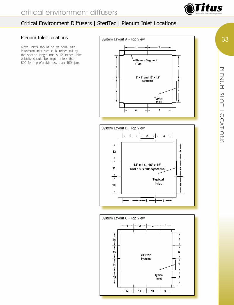
Plenum Inlet Locations
Note: Inlets should be of equal size. Maximum inlet size is 8 inches tall by the section length minus 12 inches. Inlet velocity should be kept to less than 800 fpm, preferably less than 500 fpm.
PLE
NUM SLO
T LO
CATIO
NS
critical environment diffusers
33System Layout A - Top View
System Layout B - Top View
System Layout C - Top View
Plenum Segment(Typ.)
8' x 8' and 12' x 12'Systems
TypicalInlet
1 2
3
5
4
6
7
8
14' x 14', 16' x 16'
and 18' x 18' Systems
Typical
Inlet
1 2 3
5
4
6
7
10
11
12
8
20' x 20'
Systems
Typical
Inlet
1 2 3
5
4
6
7
8
9101112
13
14
15
16
Critical Environment Diffusers | SteriTec | Plenum Inlet Locations

SPECIFIC
ATIO
NS
SteriTec-ALSteriTec-SS
Linear air curtain system marked _______ shall be Titus SteriTec system. Linear diffusers shall be constructed for a 12-inch wide plenum. The diffuser shall be a two-slot design with provision for blanking off one-slot. Linear diffusers shall include pressure induction plates for automatic balancing of airflow. Slots shall include adjustable blades with a minimum adjustment range of 5° to 15°. Diffuser shall be constructed of heavy extruded aluminum (or 20-gauge 304 stainless steel for SteriTec-SS).
An outer frame and factory manufactured plenum shall be installed on the diffuser. The diffuser must have quarter-turn fasteners for quick and easy removal from the plenum. The plenum shall have all outer corners radiused with a ¾-inch, minimum, radius.
All welded joints shall be ground smooth. (Option-plenums shall have square corners.) Plenums must be connected at all joints using bolt together flanges. The system shall have ____ inlets which shall be 5, 6 or 8 inches high and be of sufficient length to reduce the velocity of incoming air to ____ fpm or less. The corners of the system shall be interconnected using transition elbows with removable face covers. Corner transitions shall not reduce the cross
sectional area of the plenum. Removable face covers shall expose the entire corner section of the plenum for cleaning and visual inspection.
Center diffusers shall be Titus model number ________ (see model specification).
System parameters shall be as follows: Room Volume _____ft.3 Air Changes Per Hour ______ Nominal System Size ______’ x ______’ Total System cfm ______ Perimeter Air Curtain cfm ______ Number of TLF Diffusers ______ cfm/TLF Diffuser _______ cfm/Linear ft. of Slot Diffuser ______
Model Number Specification
Inlet Width Number of Number of Inlets See “Plenum Inlet
Locations” for maximum inlet size available
Perimeter cfm Interior DiffusersModel (Use inlet
location chart to determine
correct number)
Specify Specify SpecifySteriTec-ALSteriTec-SS
XXXXXXXX-XX X X X X XX XX X X
Nominal Length A* Inlet Height Total System
cfm
Interior DiffuserSpecify 5” 5 Specification
6” 6 (Add the appropriate diffuser model number specifications to the end of this specification.)
8” 8 Specify
* For standard system sizes, see page D28.
Suggested Specifications
critical environment diffusers
34
Critical Environment Diffusers | SteriTec | Specifications

Modular Surgical System Technology Models: ModuTec-D • Diffuser ModuTec-G • Grid
These Products IncludeStandard Finish • Face & Grid: #26 White Plenum: Mill
ModuTec is a 2-slot perimeter air curtain system. • Excellent for use as a perimeter air curtain in clean air • environments such as operating rooms.
Integral grid system is provided for easy installation in • the field.
Diffuser face lays in T-bar grid • eliminating the need for 1/4" turn fasteners.
Inlet can be located on right, left, or center of plenum • to allow for design flexibility in the field
Plenum has 45 degree radius corners for easy cleaning. •
Retainer cables (2 per plenum) are provided to secure • face.
Optional blank-off for diffuser face •
Construction is aluminum material for plenum and • diffuser face; aluminum material with miscellaneous steel parts for grid.
Perimeter T-bar is 1 • 1/2" wide, compatible with standard 1 1/2" wide T-bar systems by others.
OverviewModuTec is a perimeter air curtain system used to create a barrier between a clean zone and the balance of the room. The air curtain typically discharges 20 to 50 cfm per linear foot of slot. Flow rates of up to 100 cfm per linear foot can be obtained with a two-slot ModuTec diffuser. ModuTec diffusers surround TLF diffusers in operating rooms to reduce internal contaminants in the operating theatre. With limited adjustable slots, the air curtain can be directed at a slight angle to facilitate balancing airflow in the entire operating theatre through directional control.
To meet sanitizing requirements, ModuTec diffusers have plenums with 45 degree radius corners. This allows easy manual cleaning of the inside of the plenum when the face is removed and reduces crevices where bacteria and other organisms can grow. Select ModuTec diffusers based on 50 fpm terminal velocity at knee height of 24 to 36 inches above the floor – for most operating room applications.
ModuTec
TLF LaminarDiffusers
ModuTec Perimeter System
Modular Installation
Assemble perimetergrid segments with
Spline clip shown
Plenums to be installedfrom thisside of grid
Diffuser and Access Panelmay be installed from face
side of perimeter grid
DiffuserModuTec-D
Plenum
Fill pocketwith sealant
prior to plenuminstallation
Perimeter GridModuTec-G
MODUTEC
critical environment diffusers
35
Critical Environment Diffusers | ModuTec

DIM
ENSIO
NS
Dimensions
Typical System Sizes
Typical Modular Sizes
Dim 1, Dim 2
No. of Linear Diffusers Per System
Linear Flow cfm
@ 40 cfm/ft2
Laminar Flow Sizes
LaminarFlow cfm
@ 30 cfm/ft2Total cfm
6’ x 8’ (2) 6 ft., (4) 4 ft. 1,120 (4) 2x4 TLF 960 2,080
8’ x 10’ (4) 4 ft., (4) 5 ft. 1,440 (4) 2x6 TLF 1,440 2,880
10’ x 10’ (8) 5 ft. 1,600 (8) 2x4 TLF 1,920 3,520
12’ x 12’ (8) 6 ft. 1,920 (8) 2x4 TLF 1,920 3,840
10’ x 16’ (8) 5 ft., (2) 6 ft. 2,080 (14) 2x4 TLF 3,360 5,440
14’ x 14’ (8) 5 ft., (4) 4 ft. 2,240 (15) 2x4 TLF 3,600 6,440
14’ x 16’ (2) 4 ft., (8) 5 ft., (2) 6 ft. 2,400 (18) 2x4 TLF 4,320 6,720
critical environment diffusers
36Face View
ModuTec-GPerimeter GridSystem
ModuTec-DLinear Diffuser
TLF-AALaminar Diffuser
1 1/2"Tee Width 12 3/4"
Modular Plenum(shown with center inlet)
Nominal Length + 24"
Nom
inal
Len
gth
+ 2
4"
Dim
ensi
on 2
Nom
inal
Len
gth
Dimension 1Nominal Length
12"
12"
Critical Environment Diffusers | ModuTec | Dimensions

Module System Details
MODULE
SYSTEM DETAILS
critical environment diffusers
37Face View - 6 Module System
Face View - 8 Module System
DIM 1
B1
B1
DIM 2
A1DIM 1
A1
B1
DIM 2
B1
6 Module Perimeter System (ft)
System Size
Dim 1 Dim 2
Diffuser Length
B1 6 x 8 6 8 46 x 10 6 10 5
8 Module Perimeter System (ft)
System Size
Dim 1 Dim 2
Diffuser Length
A1 B18 x 8 8 8 4 48 x 10 8 10 4 58 x 12 8 12 4 610 x 10 10 10 5 510 x 12 10 10 5 612 x 12 12 12 6 6
Critical Environment Diffusers | ModuTec | Module System Details

Module System Details (continued)
MODULE
SYSTEM DETAILS
critical environment diffusers
38
10 Module Perimeter System (ft)
System Size
Dim 1
Dim 2
Diffuser Length
A1 B1 B28 x 14 8 14 4 5 410 x 14 10 14 5 5 410 x 16 10 16 5 5 612 x 14 12 14 6 5 412 x 16 12 16 6 5 612 x 18 12 18 6 6 6
Face View - 10 Module System
Face View - 12 Module System
B1
B2DIM 2
B1
A1DIM 1
A1
A1DIM 1A2A1
B1
B2
B1
DIM 2
12 Module Perimeter System (ft)
System Size
Dim 1 Dim 2
Diffuser Length
A1 A2 B1 B214 x 14 14 14 5 4 5 414 x 16 14 16 5 4 5 614 x 18 14 18 5 4 6 6
Critical Environment Diffusers | ModuTec | Module System Details
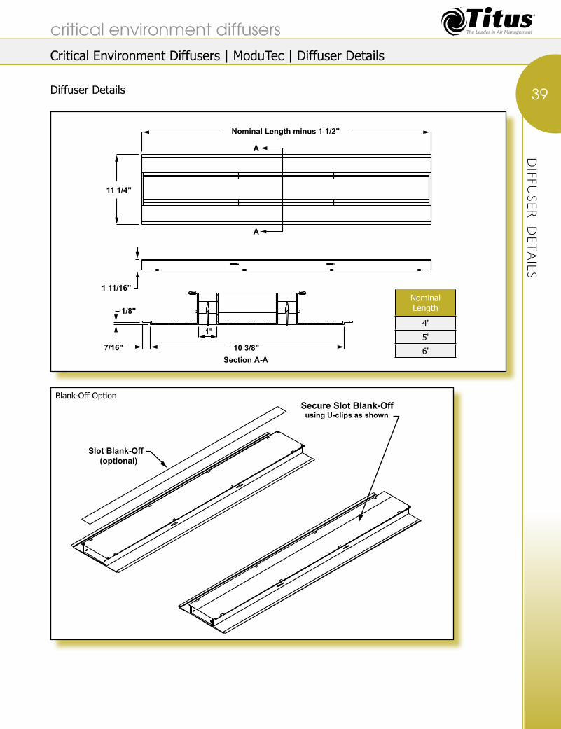
Diffuser Details
DIFFU
SER DETAILS
critical environment diffusers
39
Blank-Off Option
Section A-A
11 1/4"
Nominal Length minus 1 1/2"
1 11/16"
1/8"
1"
10 3/8"
A
A
7/16"
Slot Blank-Off (optional)
Secure Slot Blank-Off using U-clips as shown
Nominal Length
4'
5'
6'
Critical Environment Diffusers | ModuTec | Diffuser Details

Plenum Inlet Details
Grid Details
PLE
NUM DETAILS
critical environment diffusers
40
Inlet Right
Inlet Left
Inlet Center5 3/4"
5 3/4"
4"
5 1/2"
3 3/4"
11 5/8"
12"
Inlet Length
Nominal Length
Nominal Length
Inlet Length
4' 16"
5' 18"
6' 22"
Perimeter Frame Quadrant
Perimeter Frame Bridge
Access Panel
Joiner Clip Grid Tee BarRetainer Cable2 per Plenum
6 13/16"
13"
Critical Environment Diffusers | ModuTec | Plenum Details

PERFO
RMANCE DATA
Performance DataModuTec
NC is based on a 6-foot unit.• Throw is based on isothermal air, vertical, • in a room 11 feet high, for 150, 100 and 50 fpm terminal velocities, for a 6-foot unit.For cold air, throw will increase, heated air will not • project as far as shown; See the section, Engineering Guidelines and the topic, ‘Estimating Downward Vertical Projection’ in this catalog for additional information.
Throw data included in ( ) parenthesis is • calculated to exceed floor to ceiling distance for the terminal velocities shown.Static pressure shown assumes Titus • recommended plenum.Data is based on a factory provided • plenum and an 22 x 4-inch inlet.
1-Slot
Airflow, cfm/Ft. 20 30 40 50 60 70 80Static Pressure 0.016 0.037 0.067 0.105 0.150 0.206 0.268
NC (Noise Criteria) <10 <10 <10 13 16 19 24Throw 1-2-6 2-5-7 4-6-8 6-7-9 6-7-10 6-8-11 7-9-(12)
2-Slot
Airflow, cfm/Ft. 20 40 60 80 100 120 140Static Pressure 0.004 0.016 0.037 0.067 0.105 0.150 0.206
NC (Noise Criteria) <10 <10 <10 19 26 31 37Throw 0-0-4 2-4-8 5-7-10 6-8-(12) 7-9-(13) 8-10-(14) 9-11-(15)
critical environment diffusers
41
Critical Environment Diffusers | ModuTec | Performance Data
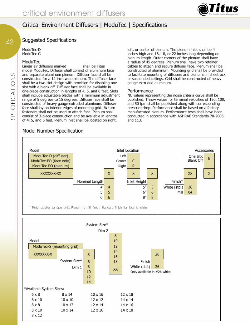
SPECIFIC
ATIO
NS
ModuTec-DModuTec-G
ModuTecLinear air diffusers marked _______ shall be Titus model ModuTec. Diffuser shall consist of aluminum face and separate aluminum plenum. Diffuser face shall be constructed for a 12-inch wide plenum. The diffuser face shall be a two-slot design with provision for disabling one slot with a blank off. Diffuser face shall be available in one-piece construction in lengths of 4, 5, and 6 feet. Slots shall include adjustable blades with a minimum adjustment range of 5 degrees to 15 degrees. Diffuser face shall be constructed of heavy gauge extruded aluminum. Diffuser face shall lay on interior edges of mounting grid. ¼ turn fasteners shall not be used to attach face. Plenum shall consist of 3-piece construction and be available in lengths of 4, 5, and 6 feet. Plenum inlet shall be located on right,
left, or center of plenum. The plenum inlet shall be 4 inches high and 16, 18, or 22 inches long depending on plenum length. Outer corners of the plenum shall have a radius of 45 degrees. Plenum shall have two retainer cables to attach and secure diffuser face. Plenum shall be constructed of aluminum. Mounting grid shall be provided to facilitate mounting of diffusers and plenums in sheetrock or suspended ceilings. Grid shall be constructed of heavy gauge extruded aluminum.
PerformanceNC values representing the noise criteria curve shall be published. Throw values for terminal velocities of 150, 100, and 50 fpm shall be published along with corresponding pressure drop. Performance shall be based on a factory manufactured plenum. Performance tests shall have been conducted in accordance with ASHRAE Standards 70-2006 and 113.
Model Number Specification
*Available System Sizes:6 x 8 8 x 14 10 x 16 12 x 186 x 10 10 x 10 12 x 12 14 x 148 x 8 10 x 12 12 x 14 14 x 168 x 10 10 x 14 12 x 16 14 x 188 x 12
System Size*
Dim 28
Model 10ModuTec-G (mounting grid) 12
XXXXXXX-X X14
2616
System Size*
Dim 1 6 18 Finish8
XXWhite (std.) 26
10 Only available in #26 white
1214
Model Inlet Location AccessoriesModuTec-D (diffuser) Left L One Slot
Blank Off BModuTec-FO (face only) Center CModuTec-PO (plenum) Right R
XXXXXXX-XX X X X XX X
Nominal Length Inlet Height Finish*4' 4 5” 5 White (std.) 265' 5 6” 6 Mill 046' 6 8” 8
* Finish applies to face only. Plenum is mill finish. Standard finish for face is white.
Suggested Specifications
critical environment diffusers
42
Critical Environment Diffusers | ModuTec | Specifications
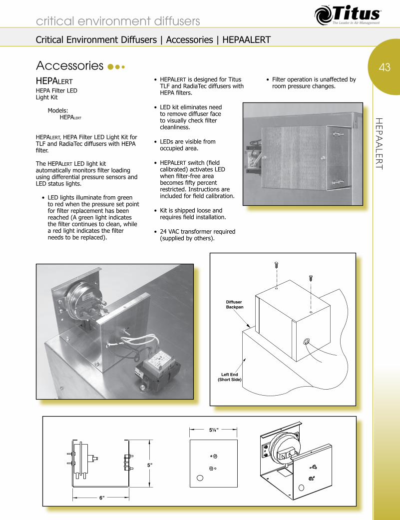
HEPAALE
RT
critical environment diffusers
43
Critical Environment Diffusers | Accessories | HEPAALERT
HEPALERTHEPA Filter LEDLight Kit Models: HEPALERT
HEPALERT, HEPA Filter LED Light Kit for TLF and RadiaTec diffusers with HEPA filter.
The HEPALERT LED light kit automatically monitors filter loading using differential pressure sensors and LED status lights.
LED lights illuminate from green • to red when the pressure set point for filter replacement has been reached (A green light indicates the filter continues to clean, while a red light indicates the filter needs to be replaced).
HEPA• LERT is designed for Titus TLF and RadiaTec diffusers with HEPA filters.
LED kit eliminates need • to remove diffuser face to visually check filter cleanliness.
LEDs are visible from • occupied area.
HEPA• LERT switch (field calibrated) activates LED when filter-free area becomes fifty percent restricted. Instructions are included for field calibration.
Kit is shipped loose and • requires field installation.
24 VAC transformer required • (supplied by others).
Filter operation is unaffected by • room pressure changes.
Accessories
5"
6"
5¼"
DiffuserBackpan
Left End(Short Side)

HEPA FILT
ER
critical environment diffusers
44
Critical Environment Diffusers | Accessories | HEPA FILTER
Filter Part Number
Nominal Size A B C D E F Effective Face
Area (Sq ft)
HF4812T 48x12 40-3/8” 5-3/4” 2-7/8” 20-7/8” 41-3/4” 4-3/8” 0.80
HF7212T 72x12 64-3/8” 5-3/4” 2-7/8” 32-7/8” 65-3/4” 4-3/8” 1.30
HF2424T 24x24 16-3/8” 17-3/4” 8-7/8” 8-7/8” 17-3/4” 16-3/8” 1.45
HF3624T 36x24 28-3/8” 17-3/4” 8-7/8” 14-7/8” 29-3/4” 16-3/8” 2.70
HF4824T 48x24 40-3/8” 17-3/4” 8-7/8” 20-7/8” 41-3/4” 16-3/8” 3.95
HF6024T 60x24 52-3/8” 17-3/4” 8-7/8” 26-7/8” 53-3/4” 16-3/8” 5.20
HF7224T 72x24 64-3/8” 17-3/4” 8-7/8” 32-7/8” 65-3/4” 16-3/8” 6.45
HF4836T 48x36 40-3/8” 29-3/4” 14-7/8” 20-7/8” 41-3/4” 28-3/8” 7.10
Accessories (continued)
HEPA Filter
Titus HEPA filters are designed specifically • to fit the Titus TLF and RadiaTec diffusers manufactured after 6/10/07. These filters will not fit diffusers manufactured before that date.Filter efficiency is 99.99% with 0.3 micron • particles per standard: IES-RP-CC-001.3 (Institute of Environmental Science & Technology).The filter resistance to air flow will be a maximum • of 0.52” water gauge at 100 fpm. Refer to chart for additional pressure drop values.Filter is scan tested for leaks at an air flow of 100 fpm.• Frame material is extruded anodized aluminum.•
Filter has a downstream gel seal to mate with diffuser • HEPA knife edge. Gel seal material is Blu-Jel.Filter media is 007 Dimple-pleat (ME-D0700). • Pack style is 2” dimple pleat.Filter is constructed of fire-rated materials • per standard: UL-900 class 1.Filter has a centerboard with (1) port for damper • operation. Cadmium plated screw (included with filter) must be inserted into port while filter is in use.The filter maximum operating temperature is 250• oF, and the maximum relative humidity (R.H.) is 100%.
Filter Specifications

HEPA FILT
ER
critical environment diffusers
45
Critical Environment Diffusers | Accessories | HEPA FILTER
Accessories (continued)
Nominal Filter Size
48 x 12cfm 50 60 70 80 90 100 110
Pressure 0.20 0.30 0.40 0.52 0.66 0.80 1.0
72 x 12cfm 59 80 100 120 140 160 180
Pressure 0.11 0.20 0.31 0.45 0.60 0.80 1.0
24 x 24cfm 90 110 130 150 170 190 205
Pressure 0.20 0.30 0.41 0.55 0.70 0.90 1.0
36 x 24cfm 160 200 240 280 300 340 380
Pressure 0.175 0.28 0.40 0.54 0.62 0.80 1.0
48 x 24cfm 200 300 360 400 430 480 520
Pressure 0.15 0.34 0.50 0.62 0.70 0.90 1.0
60 x 24cfm 400 450 500 550 600 650 700
Pressure 0.29 0.37 0.47 0.59 0.70 0.80 1.0
72 x 24cfm 300 400 500 600 700 800 900
Pressure 0.11 0.20 0.31 0.45 0.60 0.80 1.0
48 x 36cfm 400 500 600 700 800 900 1000
Pressure 0.16 0.25 0.35 0.50 0.64 0.80 1.0
Pressure loss values listed above are measured • in inches of water gauge (w.g.)Pressure loss value is for an unused filter • only. This value must be added to the diffuser pressure drop to determine total pressure.

APPLICATIO
N NOTES
critical environment diffusers
46Titus Operating Room Air Distribution System
System Sizing and Layout
System Calculations Steps:Determine room size.1. Determine desired number of air changes per hour for 2. the SteriTec perimeter air curtain and the TLF internal diffusers.Determine SteriTec nominal system size.3. Determine desired total 4. system cfm.Determine perimeter air 5. curtain cfm.Determine internal diffuser cfm (usually 50 to 75 6. percent of the total cfm).Select number of inlets and the location from the chart 7. shown.Determine number TLF units and 8. inlet size for each unit.
New ASHRAE guidelines point to providing continuous pillar of laminar airflow air distribution over the operating table and personnel as well the surgical instrument table. These guidelines indicate the laminar airflow velocity should not exceed 25-35 fpm at the patient. The reason is the laminar flow should not overcome the natural plumage of airflow from the body and allow the laminar flow to drive contaminants in a wound. New data has now been shown that space inside the “sterile field” can be used for lighting, gas connections, etc. This data shows that up to 30% of the primary supply diffuser array area may be allocated for non-diffuser use such as lights, gas columns, etc. but caution is
advised. The air curtain, or air wall, is recommended around the sterile field to stop contamination from entrainment along the ceiling line and along the outer perimeter of the airflow coming down form the TLF supply diffusers. (See page D28 for more details.) Most operating rooms are now recommended to be designed at a minimum 25 air changes per hour (ACPH). The new guidelines do not state this airflow be all outside airflow. The airflow should be highly filtered and the operating room is normally at a positively pressure. Most codes call for the return grilles to be located at the external lower wall areas above the floor level in the corners of the room. For critical operating rooms a LineaTec air curtain should be added. The air curtain provides an air wall outside the laminar airflow zone to decrease entrainment or induction into the laminar airflow perimeter. The air curtain is normally selected for a terminal velocity of 50 fpm at 2 feet. above the floor The Titus LineaTec diffuser has a deflector that can be adjusted to deflect the air stream inward or slightly outward.
*Refer to page D30 for Plenum Inlet Location diagrams.**cfm for 30 fpm see D26A.F. = Above Floor
Required System InformationRoom Volume _____ft• 3.Air Change per Hour _____.• SteriTec Dimensions _____’ x _____’.•
System Total cfm _____.• SteriTec Total cfm _____.• Number of TLF diffusers _____.• cfm per TLF diffuser _____.•
Air Changes Per Hour
Ceiling Height (ft.)
Room Dim. (ft.)
SteriTec Specifications TLF Specifications System
Total cfm
Dim. (ft.) A + B
Active Slots
System Layout*
Max Inlet Size (in.)
Inlets Required
Plenum Inlet Locations*
Total cfm
Throw (ft.) @ 50 fpm @ 2’ A.F.
No. of
unitsDim. (in.)
Inlet Size (in.)
Total cfm
Throw to 30 fpm
20 10 30 x 38 12 x 12 2 A 60 x 8 4 2, 4, 6, 8 1,920 8 8 24 x 48 12 1,920 7 3,84025 10 30 x 31 12 x 12 2 A 60 x 8 4 2, 4, 6, 8 1,920 8 8 24 x 48 12 1,920 7 3,84030 10 28 x 27.5 12 x 12 2 A 60 x 8 4 2, 4, 6, 8 1,920 8 8 24 x 48 12 1,920 7 3,84035 10 27 x 26 12 x 12 2 A 60 x 8 4 2, 4, 6, 8 1,920 8 8 24 x 48 12 1,920 7 3,84020 10 44 x 45 14 x 14 2 B 42 x 8 8 1, 3, 4, 6, 7, 9, 10, 12 2,240 8 18 24 x 48 10 4,320 7 6,56025 10 39 x 40 14 x 14 2 B 42 x 8 8 1, 3, 4, 6, 7, 9, 10, 12 2,240 8 18 24 x 48 10 4,320 7 6,56030 10 36 x 37 14 x 14 2 B 42 x 8 8 1, 3, 4, 6, 7, 9, 10, 12 2,240 8 18 24 x 48 10 4,320 7 6,56035 10 33 x 34 14 x 14 2 B 42 x 8 8 1, 3, 4, 6, 7, 9, 10, 12 2,240 8 18 24 x 48 10 4,320 7 6,560
The operating room system specifications table provides SteriTec and TLF specifications based on different combinations of ACPH and room dimensions.
Application Notes
System LayoutNominal System Length "A" plus 353/16"
Joiner mullionused betweensections - multiplesections used onlarge systemaccording tosystem size
The TLF diffuser, withor without integralHEPA filters, areplaced in the center of the SteriTec lineardiffuser assembly.The TLF laminar flow diffusers are to belocated over the entirework ares aboveand around the operatingroom table.
NominalSystem
Length "B"plus 353/16"
Nominal System Length "A"plus 1¾"
NominalSystem
Length "B"plus 1¾"
1623/32"
CornerPanel
¼ Turn Fasteners
Operating Table
SlotDiffuser
Critical Environment Diffusers | Application Notes

Operating Room Air Distribution System The discussion presented in the application notes are intended as aids to heating and air conditioning engineers and designers with skill and knowledge about clean room design. Titus has no control over the system design and application of these critical environment products, a function that rightfully belongs to the designer.
Contaminated air outside the air curtain is prevented from entering the clean zone by the air curtain. Contaminated air in the clean zone is pushed down and outward by the laminar flow on the interior of the clean zone.
The interior of the system should have the highest room pressure due to velocities and air volume from the air diffusers.
Velocities should be kept to a maximum of 35 fpm at operating table height so the natural plumage velocity of the patient is not over powered and checks possible contaminants into open wounds during surgery. The laminar flow diffuser should have quarter-turn fasteners and all internal parts shall be removable for cleaning and sterilization.
The entire operating room is usually under positive pressure created by dampering exhaust air and by providing extra makeup air. This helps to prevent an ingress of contaminated particles from outside the clean room. As doors or dividers are opened or parted, the positive internal pressure causes air to flow toward the lower external pressure outside the clean environment. The outward airflow forces particles away from the interior zone. Some hospital rooms are designed for negative pressure to keep contaminants from contaminating other hospital areas and endangering other people.
Plenums for LineaTec diffusers used in operating rooms usually have radiused corners. Corners are radiused with a ¾-inch radius to facilitate cleaning and to avoid areas where microorganisms can grow, later contaminating incoming clean air. The face of the LineaTec can be removed by rotating quarter-turn fasteners.
The entire plenum is then exposed to the maintenance worker. The plenum system is usually interconnected so a minimum number of inlets can be utilized for incoming air from the air handler.
Corner transitions are utilized so the plenum can be continuous, even at the corners. Corner transitions found on Titus plenum systems are covered on the operating room side by a cover plate. When the plate is removed, the entire plenum corner is exposed for easy cleaning. The cover plate itself can be put in an autoclave for sterilization. Some competitive models utilize an elbow behind the ceiling as corner transitions. To clean the corner transitions, the maintenance worker must reach around the corner in areas that are hidden from sight.
The operating room design engineer determines the number of ACPH based on the cleanliness level desired and current industry standards. Plenum inlets are sized so the maximum inlet velocity is in the 500 fpm range. Inlets can be lengthened and made longer to reduce entrance velocities or multiple inlets can be used. Plenum velocities should be kept as low as possible to facilitate automatic balancing of the air curtain. The 800 fpm range is considered top end, 400 to 500 fpm is desirable. Supply air velocity to the interior diffusers and the exterior air curtain should be within 5 percent of each other.
Total room airflow should be divided between the perimeter air curtain and the center diffusers. The perimeter air curtain should be supplying air between 25 to 50 cfm per foot. HEPA filters should be located remotely.
The standard material of construction is 304 stainless steel. The 304 stainless steel offers durability and an attractive appearance; plus it can withstand manual sterilization using harsh chemicals normally encountered for this purpose. The standard finish is #04 mill finish.
Manual balancing dampers should be sufficient to allow balancing of individual duct branches. Design flow rates to the interior clean zone should be established through normal balancing procedure by a certified air balancing professional. The perimeter zone should be adjusted to obtain the required cfm per foot as designed.
Application Notes (continued)
critical environment diffusers
47
APPLIC
ATIO
N NOTES
Critical Environment Diffusers | Application Notes

990 Security Row | Richardson TX 75081 | Office: 972.699.1030 | Fax: 972.680.1971| email: [email protected] | www.titus-hvac.com