critical design review - spacegrant.colorado.edu 2013/teams...• be sure to place all these files,...
TRANSCRIPT

2013 CDR
GASP Critical Design Review
Johns Hopkins and University of Maryland Brianna Brassard, Marie Hepfer, Nick Lybarger, Chris Mogni, Krysti Papadopoulos,
Lauren Powers, Corrie Russell, Kristy Weber, Mazi Wallace
11/12/2012
1

2013 CDR
CDR Delieverables
• In addition to this presentation, each school must include the following by December 10th
• Mechanical drawings in pdf format • Electrical schematics in pdf format • Signed copies of the Power and Telemetry ICDs in pdf
format • Completed Power Budget in xls format • Completed Pin Assignments in xls format • Completed Timer Event matrix in xls format • Be sure to place all these files, including ppt
presentation in your DropBox Pony Express folder by COB on December 10, 2012
2

2013 CDR
Purpose of CDR
• Confirm that: – Design is mature enough to move into the
fabrication phase – Final analysis on systems that weren’t prototyped or
needed further analysis is complete and accurate – Results of prototyping suggest the system will meet
project requirements – Manufacturing plan is in place – Testing plan is in place and sufficient to ensure
system functionality and performance in-flight – Project meets requirements of RockSat-X user’s
guide – The project is on track to be completed on time and
within budget
3

2013 CDR
CDR Presentation Outline
4
• Section 1: Mission Overview • Section 2: Design Description • Section 3: Subsystem Design • Section 4: Prototyping/Analysis • Section 5: Manufacturing Plan • Section 6: Testing Plan • Section 7: User Guide Compliance • Section 8: Project Management Plan

2013 CDR
1.0 Mission Overview Name of Presenter
5

2013 PDR
Mission Overview: Mission Statement
• Primary Objective I: Measure Electron Density in the E region (90-120km) • Primary Objective II: Test water-tight dust collection mechanism. Dust will be collected with SiO2 aerogel samples. • Secondary Objective I: Use sensors to capture data about the flight
8

2013 PDR
Mission Overview: Mission Statement
• Who will this benefit/what will your data be used for?
– Increase understanding of electron density of E-region – Test novel technique for measuring electron density of E-region – Container provides preliminary test for future JHU team experiments with Aerogels
10

2013 PDR
Mission Overview: Theory and Concepts
• Ionosphere is dispersive • Therefore, EM waves travelling along same path at different frequencies travel at different velocities • Dual frequency GPS signals return from satellite at different times • This is called a phase difference • Phase difference ~ TEC
– TEC: Total Electron Content • Electron density profile calculated by relation:
N(x, y, z, t) ~ dTEC/dt
13
GPS

2013 PDR
Mission Overview: Theory and Concepts
• What other research has been performed in the past? – Dual Frequency GPS flown on many previous space missions – Electron density measured by interferometry, radio occultations, etc in past
• Measurement by phase differences with DF-GPS is a novel technique
14

2013 PDR
Mission Overview: Theory and Concepts
• Aerogels have been used on the Star Dust mission to collect interstellar particles • Possibility of studying particle composition and other properties of upper atmosphere using aerogels • Sounding rocket missions with aerogels have been unsuccessful due to water contamination • Small quantities of water will dissolve aerogels • Proper containment and collection system necessary for any successful scientific mission • We will use SiO2 aerogels with density in the range of 90-100 kg/m^3
15
Aerogels

2013 PDR
Mission Overview: Theory and Concepts
• Research on dust collection in space has been ongoing since the 1960s • Recent papers have documented how aerogels can be used to collect dust particles
• Must put aerogel into the streamline to capture particles head on • Streamline is the curve in which the particle velocity vectors are tangent to the rocket
• See the dropbox for examples of research papers relevant to our aerogel research

2013 CDR
Mission Requirements (Level 0)
• O1: Record frequency phase shifts in the E-region using a Dual Frequency GPS
• O2: Derive an electron density profile from the phase shifts
• O3: Use aerogels to collect dust particles • O4: House aerogels in a water-tight
container • O5: Use sensors to monitor flight
12

2013 CDR
Mission Requirements (O1 Levels 1 and 2)
• O1.R1: GASP shall fly a dual frequency GPS – O1.R1.SR1: The GPS shall be unlocked for space flight – O1.R1.SR2: GASP team shall adhere to all ITAR restrictions
• O1.R2: GASP shall fly a dual frequency antenna – O1.R2.SR2: A mechanism for communicating with satellites
prior to exposure to the atmosphere shall be implemented • O1.R3: GASP shall build a housing for the GPS which
will: – Prevent outgassing – Prevent anyone from seeing the ITAR restricted hardware
• O1.R4: GASP shall provide its own power and power control for the GPS
13

2013 CDR
Mission Requirements (O2 Levels 1 and 2)
• O2.R1: GASP shall record phase shifts – GASP shall store data on its internal
memory and shall pass data through the RS-232 port
• O2.R2: GASP shall use mathematical relations to derive TEC and electron density from phase shifts
14

2013 CDR
Mission Requirements (O3 Levels 1 and 2)
• O3.R1: The linear actuator should expose the aerogel to the streamline
• O3.R2: The linear actuator should retract the aerogel back into container
15

2013 CDR
Mission Requirements (O4 Levels 1 and 2)
• O4.R1: The aerogel housing shall mechanically seal
• O4.R2: The housing shall provide an external mechanism to keep the telescoping arm in the container post collection
• O4.R3: The housing should prevent water from contaminating the aerogel sample
16

2013 CDR
Success Criteria:
– Minimum Success: • The GPS collects and records phase shift data • The sensors, which will have flown, provide detailed
information about the flight – Comprehensive Success:
• The GPS communicates with at least one satellite throughout the entire flight
• The aerogel is exposed to the atmosphere • The aerogel is retracted back into its housing • The housing protects the aerogel from water
exposure
17

2013 PDR
Mission Overview: Expected Results
11
• GPS: • Expect to measure TECs • The TECs will be used to derive an E-
region profile • Aerogel mission:
• Expect to return aerogel container with sensor readings

2013 PDR
Mission Overview: Expected Results
11
• GPS: • TEC vs. Altitude plot is being redone for an altitude range of 50-200km • We will provide an updated plot when this is completed • Old plot is given on the next page as an example

2013 PDR

2013 PDR
Mission Overview: Concept of Operations
• Receiver should power up five minutes before flight • Receiver should begin recording at point A • Receiver should stop recording at chute deploy • The Aerogel actuated gate valve should open at point B and close at point C • Linear actuator pushes aerogel outside of vacuum chamber and return aerogel to chamber between points B and C • See ConOps on next slide for definitions of point B, point C, and chute deploy
21

2013 CDR
Concept of Operations – Timed Events Matrix
22

2013 PDR
ConOps
t ≈ ?
Altitude: ?
Event A
• Side blown off; GPS begins recording
t ≈ 15 min
Splash Down
t ≈ 1.7 min
Altitude: 95 km
Event B
• LA exposes aerogel
-G switch triggered
-All systems on
-GPS begins to track location
t = 0 min
t ≈ 4.0 min
Altitude: 95 km
Event C
• Aerogel sample retracted into housing
• External door seals aerogel in housing
Apogee
t ≈ 2.8 min
Altitude: ≈115 km
End of Orion Burn
t ≈ 0.6 min
Altitude: 52 km
Altitude
t ≈ 5.5 min
Chute Deploys

2013 CDR
2.0 Design Description Name of Presenter
24

2013 CDR
Actions from PDR
25
• Aerogel density • Aerogel safety • TEC graph • Rework functional block diagram • Wallops antenna

2013 CDR
Changes Since PDR
26
• Two meetings at APL to discuss CDR and designs
• Redesigned aerogel project • Added sensors to the project • Analyzed GPS housing; in the process of
analyzing aerogel project through finite element analysis

Changes Since PDR
27
ñ GPS Subsystem Themal Vac Housing Designed New Antenna Chosen (includes L2)
ñ Payload integration subsystem designed
ñ These changes do not affect our objectives

Func(onal Block Diagram
Humidity Sensor Aerogel
Motor

Mechanical Elements: GPS Insulation
29
CerMax™ Extreme High Temperature Ceramic Fiber Paper will be used to insulate the GPS chamber. • Capable of withstanding temperatures up to
2300 ⁰F • Will be used to keep GPS below working
temperature of 131 ⁰F
FlameShield™ Liquid Gel Adhesive/Sealant will be used to seal the casing of the GPS chamber. • Capable of withstanding temperatures up to
2000 ⁰F • Used to seal the chamber for waterproofing,
sealant needs to also withstand high temperatures

Mechanical Elements: GPS Casing
30
!
!
"
"
#
#
$
$
% %
& &
' '
( (
)*++,-!--./-!-
(0%12
'*+'3+(
4%
5/6
%770.8+(
99:;<<;: !"=>="?!"
(16-2.
@AB;CDEF<DG;<H
,I,J+
)IK+
')'%J+
0+8
LM""
!M>>
#M>$
M!#
LM!?M$"
M!#
"M$N
MO?

Mechanical Elements: GPS Case Port Holes
31
!
!
"
"
#
#
$
$
% %
& &
' '
( (
)*++,-!--./-!-
(0%12
'*+'3+(
4%
5/6
%770.8+(
99:;<<;: !"=>="?!"
(16-2.
@A<BC;<DBE:FGH
,I,J+
)IK+
')'%J+
0+8
#L>$
!L>>
L#?
L!?
L!#LMML>M
L""
LM#

Mechanical Design Elements – Aerogel Payload
32
• Aluminum will be used for outer casing, truss structure, door, and aerogel array.
• Stress/strain analysis to be done in very near future using SolidWorks

!
!
"
"
#
#
$
$
% %
& &
' '
( (
)*++,-!--./-!-
(0%12
'*+'3+(
4%
5/6
%770.8+(
99:;<<;: !"=>="?!"
(16-2.
@AB;CDEF<DG;<H
,I,J+
)IK+
')'%J+
0+8
LM""
!M>>
#M>$
M!#
LM!?M$"
M!#
"M$N
MO?
Aerogel Payload

Aerogel Payload

Aerogel Array and Arm

Aerogel Array and Arm

Electrical Design Elements
37
Power Switching: ñ GSE-1 line converted to usable voltage (5-7.5V)
– GPS • On/Off conditional on GSE-1 line present.
– Payload Control/Aerogel Sybsystem • When GSE-1 signal given, piezoelectric sensor
senses for launch vibrations. • When launch occurs, circuit completes and
systems on. SR latch used so if GSE off after launch, subsystem still on.

Electrical Design Elements
38
Sensor SEN-09196 BMP085 RHT03 GP2Y0A21YK
FirgelliL12
Type Piezo-Electric Sensor
Pressure and Temperature Sensor
Humidity Sensor Proximity Sensor
Linear Actuator Position State
Purpose Detects when launch initialiazes
Determine if and when skin has been edjected
Determine if water has entered the vacuum sealed chamber upon splashdown
Determine if and when skin has been edjected
Provide feed back on state of linear actuator
Location Payload Control System
Payload Control Unit
Aerogel Subsystem Vacuum Chamber
Payload Control Unit
Aerogel Subsystem
Voltage None required 3.3V 3.3V 3.3V 5V and Vref
Potential Cause of Failure
Launch vibrations not detected
Pressure leak but Skin not ejected
Subsystem omponent outgasing may be seen
IR from Sun may affect sensor
Connection Failure through Hbridge and breakout

Electrical Design Elements
39
Pressure Sensor-Arduino interface

Electrical Design Elements
40
Proximity Sensor-Arduino interface

Electrical Design Elements
41
Humidity Sensor-Arduino interface

Electrical Design Elements
42
Linear Actuator-Arduino interface

Software Design Elements
43
Begin collec(ng data from sensors
Rocket casing off?
Extend linear actuator
Reached 95 km?
Data from proximity sensor
Al(metry data from pressure sensor
Al(metry data from pressure sensor
Reached 95 km?
No
Yes
No
No
Yes
Yes
Retract linear
actuator
Arduino Pro

2013 CDR
De-Scopes and Off-Ramps
44
• All portions of our project are low risk; no off-ramps planned in case of budget/time constraints
• All objectives from PDR presentation remain feasible

2013 CDR
3.0 GPS Subsystem Design Name of Presenter
45

GPS Subsystem Design
46
grandpmr.com
Power – Subsystem independently powered by Li-ion 7.2V 1.37 Ah battery – Up to 10 hrs runtime – Small voltage from Power Control System acts like an on/off switch
Data – ITAR Restricted
Mechanical and Electrical Interfaces – Reciever interfaces with Power, Antenna (TNC Female) and Rocket (RS232)
Weight – 435g (reciever) + 150g (antenna) = 585g total for Subsystem
Critical Technology Used – GPS reciever: ITAR Restricted – Dual feed omnidirectiona Antenna: Antcom G5
Current Issues – Must develop waterproof and insulated housing for reciever

2013 CDR
3.0 Aerogel Design Name of Presenter
47

Aerogel Subsystems
Aerogel Experiment
Mechanical Subsystems
Linear Actuator
Electrical Subsystem
Subsystem Design: Aerogels
Press. & Hum.
Sensors
Arduino
Motor Microprocessor

Subsystem Design: Linear Actuator
49
hPp://www.firgelli.com/Uploads/ID2IMAGE1314766540.
Power – Activated by MCU and motor microprocessor
to extend and bring aerogel back into chamber
– 6-12 VDC Mechanical and Electrical Interfaces
– LA interfaces directly to the VC, EPS, and aerogel
Weight – ~84 g
Critical Technology Used – Responsible for exposing aerogel directly to
space environment Current Issues
– Need to finalize selection , potential LA is the Firgelli L16 with 140mm stroke length
hPp://www.ultramo(on.com/images/pv_bug1.jpg

Subsystem Design: Aerogel Experiment
50
Data – Aerogel acts a storage mechanism for particles
being studied – Further analysis after retrieval will verify results
of experiment Mechanical and Electrical Interfaces
– Aerogel sample is directly interfaced with the LA Weight
– ~0.00075g Critical Technology Used
– LA Current Issues
– Must make sure aerogel array will be able to withstand vibrations and be able to prevent damage or contamination to aerogel

Subsystem Design: Aerogel Electrical Subsystem
51
Power – Subsystem powers motors which are
actuated during the duration of the aerogel experiment and takes data from sensors
– 5VDC input Data
– An Arduino will be programmed to send the proper signal to motor microprocessor in order to extend and retract arm with aerogel array
Mechanical and Electrical Interfaces – Interfaces with EPS, LA, sensors, and
Rocket Critical Technology Used
– Rocket interface, LA, sensors Current Issues
– Must make sure that algorithm of Arduino will be executed properly
hPps://dlnmh9ip6v2uc.cloudfront.net/images/products/1/0/9/1/5/10915-‐01.jpg

Subsystem Design: Aerogel Electrical Subsystem
52
Power – Sensors have input of 3.3V provided by Arduino
Data – An RHT03 humidity sensor will be used to verify
success of experiment (water contamination) – A BMP085 pressure sensor will allow for payload to
recognize its location based on atmospheric pressure, in order to extend and retract arm and also the verify experiment success after splashdown
Mechanical and Electrical Interfaces – Interfaces with EPS, Aerogel chamber, and Rocket
Critical Technology Used – Aerogel Chamber, Arduino
Current Issues – Must make sure that sensors will be integrated
properly into payload
hPp://www.adafruit.com/index.php?main_page=popup_image&pID=391
hPps://dlnmh9ip6v2uc.cloudfront.net/images/products/1/0/1/6/7/10167-‐01.jpg

Subsystem Design: Aerogel Electrical Subsystem
53
Power – Subsystem powers motors which are
actuated during the duration of the aerogel experiment
– Input of 6-12VDC Data
– A Firgelli Linear Actuator Control Board interfaced to Arduino will be used to verify arm position along with speed and direction motor will be run at
Mechanical and Electrical Interfaces – Interfaces with EPS, LA, and Arduino
Critical Technology Used – LA, Arduino
Current Issues – Must make sure that Control Board is
properly integrated between Arduino and LA
hPp://www.firgelli.com/Uploads/ID2IMAGE1314766661.

2013 CDR
Organizational Chart
54
Project Manager Marie Hepfer
Lead System Engineer + Aerogel
Science Chris Mogni
Organization JHU EPS Department
Faculty Advisor Darren Waugh
Organization JHU APL
Mentors Ethan Miller
Jonnathan Fenske
Aerogel Science Nick Lybarger
GPS Team Lead Krysti Papadopoulos
Aerogel Build Lead Lauren Powers
Lead Aerogel Engineer
Kristy Webber
GPS Aerospace Engineer
Brianna Brassard Aerogel Aerospace Engineer
Mazi Wallace
Systems Engineer + Lead Electrical
Engineer Corrie Russell

2013 CDR
4.0 Prototyping/Analysis Name of Presenter
55

2013 CDR
Analysis Results
56
• Finite Element Analysis is being conducted in Solid Works for the aerogel project
• Thermal analysis on GPS housing provided on next slide

57
Temperature Effects on GPS Casing
€
δ = α(ΔΤ)(L)
€
δ =
€
δ =
(12.9*10-‐6/°F)(500°F-‐68.1°F)(6.2205in)
0.0347in
Highest Reentry Temperature: 500°F Average Lowest Temperature for Wallops, VA in August*: 68.1°F Longest Casing Dimension: 6.2205 in
*Need max change in length due to temperature so pick average low temperature for Wallops, VA. Also Why the longest casing dimension is chosen for calcula(on.

2013 CDR
Prototyping Results
58
• Prototyping will take place during our Winter Session in January
• See next slide for prototyping plan

Date Test Risks Mi(gated/Func(onality Tested
Jan Sea Level Test Electrical func(onality. Power-‐up in (mely fashion, satellites tracked, and loca(on cross verified with other GPS, i.e. iPhone. Data stores in memory.
Jan Antenna Test Antenna truly omni-‐direc(onal. Diagrams of maximum field of view created. Verify that Antenna will work inside housing material.
Jan-‐Feb TEC inferring test Dual frequency capability verified. TEC algorithm developed and referenced with heritage data.
Jan-‐Feb Waterproof test Develop and test casing tested for waterproofing.
Feb-‐Mar Thermo-‐Vac test Rocket and space environment simulated. Casing Internal temperature within -‐30 C and +55 C
Feb-‐Mar Flight Simula(on Data collected at various al(tudes and loca(ons (with weather balloon). Simula(on solware used.
Mar-‐Apr Integrated Shock Test
Flight's Gees, linear velocity, and rota(on simulated. GPS works at real (me kinema(c accuracy.
Apr Project Integra(on Fits into payload board. Test with other systems.
Test/Prototyping Plan GPS
2013 CDR
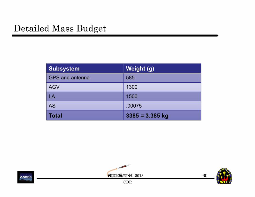
Detailed Mass Budget
60
Subsystem Weight (g) GPS and antenna 585
AGV 1300
LA 1500
AS .00075
Total 3385 = 3.385 kg

Detailed Power Budget
61
Subsystem Voltage (V) Max Current (A)
Start Time (min)
Time On (min) WaPs Ah
GPS 7.2 1.37 T -‐ 5 20 9.86 0.274
Linear Actuator 12.0 0.65 T -‐ 5 20 7.80 0.130
Arduino Pro 5.0 0.56 T -‐ 5 20 2.80 0.112
Total* – 2.58 – – 20.46 0.52
Total Power Capacity 1.00
Over/Under 0.48
# of Flights Margin 1.9
*We will be using external power sources for all subsystems, so our power usage should not contribute to the total power usage for our deck.

Wallops Interfacing: Power
62
Power Pin Function Intended Use 1 GSE 1 Provide 5 minute lead time to launch
2 Timer Event 1 (R-A) (no current use)
3 Timer Event 2 (R-B) (no current use)
4 Timer Event 3 (NR-1) (reserved for WV)
5 GND GND
6 GND GND
7 GND GND
8 GND GND
9 GSE 2 (reserved for WV)
10 Timer Event 4 (NR-2) (reserved for WV)
11 Timer Event 5 (NR-3) (reserved for WV)
12 GND (reserved for WV)
13 GND (reserved for WV)
14 GND (reserved for WV)
15 GND (reserved for WV)

Wallops Interfacing: Telemetry
63
Telemetry Function Intended Use Telemetry Function Intended Use 1 Analog 1 Data from sensors 20 Parallel Bit 7 (no current use)
2 Analog 2 Data from sensors 21 Parallel Bit 8 (no current use)
3 Analog 3 Data from sensors 22 Parallel Bit 9 (reserved for WV)
4 Analog 4 Data from sensors 23 Parallel Bit 10 (reserved for WV)
5 Analog 5 Data from sensors 24 Parallel Bit 11 (reserved for WV)
6 Analog 6 (reserved for WV) 25 Parallel Bit 12 (reserved for WV)
7 Analog 7 (reserved for WV) 26 Parallel Bit 13 (reserved for WV)
8 Analog 8 (reserved for WV) 27 Parallel Bit 14 (reserved for WV)
9 Analog 9 (reserved for WV) 28 Parallel Bit 15 (reserved for WV)
10 Analog 10 (reserved for WV) 29 Parallel Bit 16 (LSB) (reserved for WV)
11 Parallel Bit 1 (MSB) (no current use) 30 Parallel Read Strobe (no current use)
12 Parallel Bit 2 (no current use) 31 N/C N/C
13 Parallel Bit 3 (no current use) 32 RS-232 Data (TP1) Transfer data from GPS
14 Parallel Bit 4 (no current use) 33 RS-232 GND (TP2) GND for RS-232 Data
15 Parallel Bit 5 (no current use) 34 N/C N/C
16 Parallel Bit 6 (no current use) 35 N/C N/C
17 N/C N/C 36 Ground (reserved for WV)
18 Ground GND 37 Ground (reserved for WV)
19 Ground GND

2013 CDR
5.0 Manufacturing Plan Name of Presenter
64

2013 CDR
Mechanical Elements
65
• We are manufacturing everything except for the linear actuator
• Post-CDR: Buy Parts • Jan 2013: Building (at UMD and APL) • Feb 2013: Testing

2013 CDR
Electrical Elements
66
• Manufacturing/Soldering to be done • Payload Control Unit (sensors and Microprocessor must be procured) • Power Block(converter components must be procured)
• Plan/Schedule • Power Block: Design (Jan), PCB/Soldering (Feb) • Payload Control Unit: Design (Jan), PCB/Soldering (Feb) • Integration into Aerogel Subsystem (Mar)

2013 CDR
Software Elements
67
• Microprocessor code must be written and blocs must be integrated
• Bloc Dependency Previously Mentioned • Software tested as Payload Control Unit
designed

2013 CDR
6.0 Testing Plan Name of Presenter
68

2013 CDR
Electrical Testing
69
Subsystem Test Overview When
GPS Output GPS Verify Baud and bitrate of GPS output. Jan
GPS Power/Comm
GPS Verify power port acts like a switch. Verify batteries/antenna will last flight duration.
Jan
Power Block Power Block Verify converter works. Jan/Feb
Piezo-Switch Payload Control Subsystem
Verify vibration to voltage relationship. Determine threshold for launch.Verify latch works and is consistent.
Feb
Demodulator Payload Control System
Verify Microprocessor can communicate with Analog and Digital pins. Check Baud/data rate.
Feb
Sensors/LA feedback
Payload Control/Aerogel
Verify sensor calibration and sequencing. Optimal LA feedback setting should be selected.
Jan-Feb

2013 CDR
Electrical Testing
70
• High Voltage Component: Potential the Piezoelectric Sensor
(+- 90V) but only upon very high vibrations. Will buffer with voltage follower or other method.
• Internally Powered Components will be tested during sample runtime missions for battery depletion – GPS Subsystem – Aerogel Subsystem – Microprocessor/Sensors
• Only inhibit for Wallops testing is facility to charge batteries

2013 CDR
Software Testing
71
Most of the software is needed for electrical design of sensor interfaces and LA movement (no Software for GPS subsystem)
Code written/tested independantly as each sensor/subsystem is designed and developed. (Jan-Feb)
Integrated code developed and tested with mission sequence
in mind during the sensor integration phase.(Feb-Mar) Software for post-flight data testing will also be in the
works. (Mar-July)

System Level Testing
72
• Integration of GPS and Aerogel components to function as a cohesive unit. • Tests will performed to simulate sensor outputs and deployment mechanisms. • Thermal Vacuum Chamber testing will be used to verify and ensure that the desired mechanical, electrical, and structural tasks will perform in flight temperature conditions.

System Level Testing Timeline
73
• Testing will occur throughout the build process and during the months proceeding the launch.
• December: Design Completion • January–February: Initial testing of sensors and structural components during building process. • February–April: Integration testing of GPS and Aerogel unit. Thermal vacuum chamber testing. • April–May: Software Testing • May–July: Final Systems and Integration Testing
• Possibility for an addition Thermal Vacuum Chamber Test and Drop Test.

Mechanical Testing
74
• Verify payload is within the weight requirement and fits within the capsule constraints. • Perform vibrations testing of integrated payload.
• Approximate Testing Date: March 2013 • Thermal Vacuum Chamber testing will verify that the structure can withstand the temperature changed during flight.
• Approximate Testing Date: March 2013

Structural Testing
75
• Use Solidworks drawing software to perform stress and strain analysis on the aerogel compartment structure.
• Approximate Testing Date: January 2013 • Conduct a Smoke Test to verify that the system is waterproof and can withstand the landing environment.
• Approximate Test Date: February 2013 • Perform a Drop Test to confirm that the payload can withstand impact forces.
• Approximate Testing Date: March/April 2013

Mechanical Deployment Testing
76
• Testing for the deployment system will include: • Confirm that the linear actuator moves in and out of the vacuum-sealed container without failures or hesitations.
• Door opening and closing mechanism: • Verify that the container door opens and closes properly and completely without gaps in the connection area.
• O-ring testing: • Perform a submersion test to confirm that the O-ring seal is tight and no water will get into the container.

Electrical Testing: Aerogel
77
• Verification of working sensors: pressure and humidity sensors. • Allow sensors to run while testing the
linear actuator. • Sensor readings should show that the
linear actuator is functioning as desired. • Test Arduino Pro and all other components to
confirm that they have the correct voltages. • Verify circuitry is correct and complete.
Test Date for all Electrics: January – early February 2013

Internally Powered Components
78
• The following components on the integrated payload will be internally powered. • GPS • Arduino Pro • Motor for Linear Actuator

Software Testing: Aerogel
79
• Test Arduino outside of the system to verify that it functions properly and produces the desired information • Algorithm testing • Approximate Test Dates: January and February 2013
• Confirm that the motor and the sensors are communicating. • Sensors should produce accurate and
consistent data for each task performed. • Approximate Testing Date: March and April 2013
• Simulation Testing for system operation verification. • Approximate Testing Date: April and May 2013

2013 CDR
7.0 User Guide Compliance Name of Presenter
80

User Guide Compliance
81
Requirement Status/Reason (if needed)
Center of gravity in 1" plane of plate?
Max Height < 12" < 5.5’’ (sharing with WV)
Within Keep-‐Out
Using < 10 A/D Lines < 5 A/D Line (sharing with WV)
Using/Understand Parallel Line Currently not using
Using/Understand Asynchronous Line 9200 Baud
Using X GSE Line(s) 1 (per requirement)
Using X Redundant Power Lines Currently not using
Using X Non-‐Redundant Power Lines Will not use
Using < 1 Ah External power sources
Using <= 28 V < 28 V (will not have to conformal coat)

2013 CDR
Sharing Logistics
82
• We are sharing with West Virginia University – Project: Unknown
• Plan for collaboration – The JHU team has put together a forum to help our
team communicate; we have invited WVU to our collaboration forum
– We will share designs via the forum; we would like to share a dropbox folder for designs
• We have not met with the sharing team • POC: Alex Bouvy ([email protected])

2013 CDR
8.0 Project Management Plan Name of Presenter
83

2013 CDR
Schedule
84
Item Date Submit proposals 14-Dec
Order Parts As soon as we have money
Contruction Begins January 7th
GPS Thermal Casing Finished by January 11th
Vacuum Box Finished by January 18th
Vacuum Box Linear Actuator integration Finished January 25th
Entire Assembly Finished February 8th
Testing
GPS Programming Testing Starts January 7th
GPS Casing Testing Starts January 14th
Aerogel Vacuum Box Testing Starts January 28th
Entire Assembly Testing Starts February 11

2013 CDR
RockSat-X Schedule
85
12/11/2012 Critical Design Review (CDR) Teleconference 12/15/2012 Post CDR Action Item Generation 1/18/2013 Final Down Select—Flights Awarded TBA Wallops DR 01/28/2013 Post CDR Action Item Review 02/18/2013 First Installment Due 02/18/2013 Individual Subsystem Testing Reports Due 02/19/2013 Individual Subsystem Testing Reports Teleconference 02/25/2013 Experiment Decks and Connectors Sent To Customers 03/18/2013 Payload Subsystem Integration and Testing Report Due 03/19/2012 Payload Subsystem Integration and Testing Report Teleconference 04/08/2013 Final Installment Due 04/15/2013 First DITL Test Report Due 04/16/2012 DITL 1 Teleconferences 05/06/2013 Weekly Teleconferences Begin 05/13/2013 Weekly Teleconference 1 05/13/2013 Second DITL Test Report Due 05/14/2013 Weekly Teleconference 2 (2nd DITL Presentations) 05/20/2013 Weekly Teleconference 3 05/27/2013 Weekly Teleconference 4 (Travel Logistics) 06/03/2013 Integration Readiness Review Packages (IRR) Due 06/04/2013 Integration Readiness Review Telecons with Wallops 06/18/2013 GSE Checkouts At Refuge 06/19>24/2013
Testing and Environmental With Wallops 07/01/2013 Weekly Teleconferences Resume 07/22/2013 Launch Readiness Review Packages (LRR) Due 07/23/2013
Launch Readiness Review Telecons with Wallops 08/01/2013 GSE Checkouts at Refuge Inn 08/02>07/2013 Final Integration at Wallops 08/08/2013 LAUNCH 08/09/2013 Contingency Launch

2013 CDR
Budget
86
- Aerogel Project: ~$1,000 - GPS Project: ~$300 - Spare Parts: ~$200 - Travel: ~$5,000 - Deposit: $2,000 - Other RockSat-X Costs: $12,000 - Margin of Error: 10% - Initial Deposit Paid - SSL Providing Funds for Aerogel - Maryland Space Consortium Providing Funds for RockSat-X Costs - APL Providing Materials for GPS

2013 CDR
Team Availability Matrix
87

2013 CDR
Contact Matrix
88

2013 CDR
Mission Accomplished
89