criterions for prediction and control of by william h .../67531/metadc57542/m2/1/high_res_d/... ·...
TRANSCRIPT

,
TECHNICAL NOTE 3506
CRITERIONS FOR PREDICTION AND CONTROL OF
RAM -JET FLOW PULSATIONS
By William H. Sterbentz and John C. Eward
Lewis Flight Propulsion Laboratory
Cleveland, Ohio
Washington
August 1955
-q q --,,
. . . . ..
.
---- . . .---- .,. -

TECHLIBRARY-s NM
Ilfllllfllol!ulllllnlllNATIONAL ADVISORY C~ FOR AERONAUTICS
OObbLJ4
CRITERIONS
TECHNICAL NOTE 3506
FOR PREDICI’1ONANl)CONTROL
RAM-JET FLOW FWLSATIONS1
By Wi31iam H. Sterbentz and John C.
SUMMARY
OF
Evvard
The results of a theoretical and experimental study of ram-jetdiffuser flow pulsing, conmmnly referred to as a “buzz condition,” withand without combustion are presented herein. The theoretical approachto the problem is a simplified treatment of the ram jet likened to actas a Helmholtz resonator. Experimental verification of the theoreticalresults was obtained from investigations of various rsm jets.
The theory indicated that for the case without combustion a ram,
y, jet will resonate if the curve of diffuser pressure recovery as a functionof engine mass flow has a positive slo~e of sufficient magnitude. At
5 operating conditions where the slo~e of this curve is less than thecritical value, the ram jet will not resonate. These theoreticalresonance criterions reasonably predicted the occurrence of diffuser-flow pulsations.
For the case with combustion, the rate of heat addition has animportant effect in that the ram-jet resonance properties are markedlyand complexly altered. In experiments with a 16-inch ram jet, diffuser-flow pulsations occurred with heat addition at conditions w~ere pulsation-free flow was obtained without combustion. The occurrence of thesepulsations with heat addition was theoreticall.ypredicted on the basisof the resonance properties of the engine. Also presented herein is adiscussion of some possible means of eliminating or minimizing diffuser-flow pulsations.
The theoretical resonance frequency for the case without combustionchecks the experimental frequency reasonably well both as to magnitudeand trend. With combustion, the lowest value of the measured frequencywas approximately twice the theoretical fundamental frequency.
%3upersedes NACA RM E51C27, “Criterions for Prediction and Controlof Rem-Jet Flow Pulsations” by William H. Sterbentz and John C. Eward~1951.c.
_.—- . . .——

2
—..—.. .——.
.
iNTROllUCTION
Certain ram-jet supersonic diffusers
N&2A TN 3506
.
.exhibit pulsating or surging
operating chsracteristi&. This condition of operation may occur withor without combustion in the engine. Because ofpossible seriouslosses in engine thrust and efficiency (ref. 1), undesirable influenceson combustion, or failures in engine or airplane structural members}these pulsations shouldbe avoided. Before beginning a specific dis-cussion of the pulsating characteristicsof rsm jets, it is advantageousto briefly mention some of the obsened properties of ram-jet flowpulsations.
The fist commonly observed flow pulsation is the so-called %uzzcondition” occurring in ram jets having external compression diffuserseither with or without conibustionintie engine. This flow pulsationhas a frequency range of approximately 1 or 2 to 70 or 80 cycles per sec-ond. In some ram jets, these pulsationsare manifested over the entiresubcritical mass-flow range and fo~ othersl only over certain portions .
of the subcritical mass-flow range.
The occurrence of a “buzz condition” in ram jets itithexternalu
compression diffusers is related in reference 2 to the presence of avelocity discontinuity downstream of the intersection of two shock waves.Flow fluctuations start when this discontinuity or slip line just entersor leaves the diffuser cowling. Flow pulsations have also been observedconcurrently with flow separation from the surface of a diffuser spike,particularly at large angles of attack.
With combustion in the ram jet, flow pulsations may arise fromperiodic explosions of the fuel-air mixture or from fuel flow pulsations.These pulsations may lead to the generation of later&l or longitudinalwaves in the combustion chamber. (See ref. 8.) Any one or all theseflow oscillations may occur simultaneously during operation of a rsmjet.
The buzz-type flow pulsations have in common at least the followingthree physical characteristics: (1) The pulsations are characterizedby a cyclic rise and fall of pressure within the engine; (2) *hesecyclic pressure variations occur either with or without combustion inthe ram jet; and (3) the frequency and wave characteristics of flowpulsations for a given diffuser are dependent upon the internal geometryof the ram jet. In some cases, the rise and the fall of pressure hasa simple sine-wave characteristic and in others, a more complex typeof “relaxationoscillation” wave characteristic. These aspects suggesta physical phenomenon-followingthe laws of acoustical resonance.
.
_—

NACA TN 3506 3
Evidence suggesting that consideration should be given an acous-tical resonance analysis also lies in the results of work with unsteadyoperation of compressor-duct systems. The surging of these s~temsrequires that the compressor performsace curve (compressor-outletpressure as a function of mass-flow rate) have a positive slope (ref. 4)and the duct system to which the compressor is connected determinesthe frequency and the smplitude of the pulsation. The frequency ofthese pulsations maybe theoretically evaluatedby assuming that thesystem acts as a Helmholtz resonator. (See ref. 5.) Xn fact, reference6 suggests that a similar criterion might be applied for the occurrenceof rsm-jet diffuser “buzz.” The degree to which the acoustical proper-ties of the ram jet resemble those of either cm organ pipe or a Hehnholtzresonator, however, may depend on the geometry of the particular unit.
The effect of smallhas been investigated atthat the ram jet acts inpies of the conservation
flow disturbances on ~am-jet diffuser stabilitythe NACA Lewis laboratory using the assumptioneffect as a Helmholtz resonator. The princi-of mass, momentum, and ener~ were applied in
~ simplified one-dimensional an~ysis of the resonance properties ofram jets both with and without heat adtition. Experimental data frominvestigations covering a variety of conditions and engine geometriesare included as comparisons with the theoretical trends.
SYMBOLS
The following syibols sre used in this report:
A
a
‘%
f
H
K1&v~
‘c
%)
M
area, sq
velocity
specific
ft “
of sound, ft~sec
heat at comtant pressure, Btu/(lb)(°F)
frequency, cps
lower heating value of fuel, Btu/lb
constants
combustion-chambeclength, ft
diffuser length, ft
M,ac.hnumber
——— . .— .—.— .- —

..-. . ..— . -—
4’
m
%
%
h
P
AP
R
T
AT
t
u
Au
v
‘c
‘D
‘T,
‘A
‘c
WD
MACA TN 3506
mass flow, slugs/see
mass fuel flow, slugs/see
diffuser maximum mass flow, slugs/see
mass-flow perturbation, slugs/see
total pressure, lb/sq ft abs
pressure yerturl)ation,lb/sq ft
gas constant, sq ft/(sec2)(%)
total temperature, ‘R
temperature perturbation, %
time, sec
velocity, ft/sec .
velocity perturbation, ft/sec
approximation of effective storage volume of ram jet(VT - AILD)j CU ft
conibustion-chamberstorage volume between stations 2 and 4at uniform temperature T4 for case with combustion or at /uniform temperature T2 for case without combustion, cu ft
diffuser storage volume between stations 2temperature T2, cu ft (symbol used Od-Y
combustion)
total volume of ram jet, cu ft
and 4 at uniformin case with
mass of virtual oscillating air column, slugs
mass of gas intemperaturetemperature
mass of gas intemperature
combustion)
rsmT4
T2
rsm
T2>
jet between stations 2 and4 at uniformfor case with combustion or at uniform
for case without combustion, slugs
jet between stations 2 and 4 at uniformslugs (symbol used only in case with “
_—.——
TN 3506 5
.
.
.
NACA
1-
b
P
T
ratio of specific heats
combustion efficiency
density, slugs/cu ft .
total-temperature ratio across combustion chamber-and outletnozzle, T4/T2
Subscripts:
o
1
2
3
4
b
c
c
D*
s
x,y
equivalent free-stream condition
diffuser inlet
indefinite diffuser“are theoretically
station after which velocity perturbationsconsidered negligible
combustion-chamber outlet
exhaust-nozzle outlet
burning
combustion chamber
compression
diffuser
stored
area divisions in diffuser at station 2
FUIS.ATIONWITHOUT COMBUSTION
Theory
In a continuous, steady-flow ram jet, thethe combustion chamber an.air flow thatis exactly equal to the air
diffuser delivers to
flow leaving the outlet nozzle. During transient pressure oscillations,however, from whatever the source, the instantaneous air flow ~to the ram-jet combustion chamber need not be the same as the instan-taneous air flow m4 leaving the outlet nozzle. Such a condition
—. ..——— -— — .—

—.. .— _
6 NACATN 3506
leads to either a storage or an evacuation of air mass in the conibus-tion chamber. The resonant properties of the ram jet are controlledby the balance between the mass-flow delivery characteristics of thediffuser, the storage capacity of the combustion chamber, and thedischsrge effectiveness of the exit set.
Analytical treatment of the exact flowmechanism occurring inthe diffuser is complicated by the fact that the air in the Mffuserhas the properties of both compressibility,thereby including diffuservolume in the storage volume of the ram jet, and inertia, which isassumed to arise from a virtual oscillating air column. In theinterests of simplification, the virtual oscillating air column isassumed to have an approximately constant cross-sectional sxea Al,
and a length extending from station 1 to the indefinite station 2.Thus, except for the exit nozzle, the ram jet reseniblesa Hehnholtzresonator in which an oscillating air column (“air piston”) occupiesa portion of the diffuser. In a sense, then, the theory implies theexistence of a virtual separation of the perturbed flow from thediffuser walls during pulsation. Schematic com&arisons of two ram-jet configurations and aHelmholtz resonator showing the assumed aircolumn are given in figure 1.
Conservation of mass through the system reqties that
(1)
In the anslysis, the symbol A is used throughout to designate smalldeviations from mean quantities. The differential equation of themotion is obtained by systematic calculation of the terms in equa-tion (1) ss functions of the velocity perturbation of the tiffuser aircolumn and the mean flow parameters of the engine.
The pertuzbed mass-flow rate past station 2 wiIl be the sum of theperturbed mass-flow rates ~ through the area of the assumed air
COhD.111 and ~ through the residual area
Am2 =&+9
at station 2. Thus,
(2)

..
,
NACA TN 3506 -
The general eqyation for mass-flow rate is
PAum=
‘TF++M2):’
7
(i3)
For small deviations (A) from the mean quantities, equation (3)may be written
&=Au AT+Ap—-m u T F
(4)
when teims of order M? or smaller have been neglected with respectto unity. Consistent with the assumption that the inertia of the flowthrough Ay changes negligibly, Au/u for this area is omitted.
Substitution of equation (4) in equation (2) then yields
(5)
Even though all globules of the fluid initially have free-streamstagnation temperature, they are submitted to adiabatic compressionsduring transit through the engine. The changes in stagnation tenrpera-ture are related to pressure changes by the isentropic relation
Therefore equation (5) maybe stated as
(6)
(7)
—-— —.. ____ ~— .. .
8
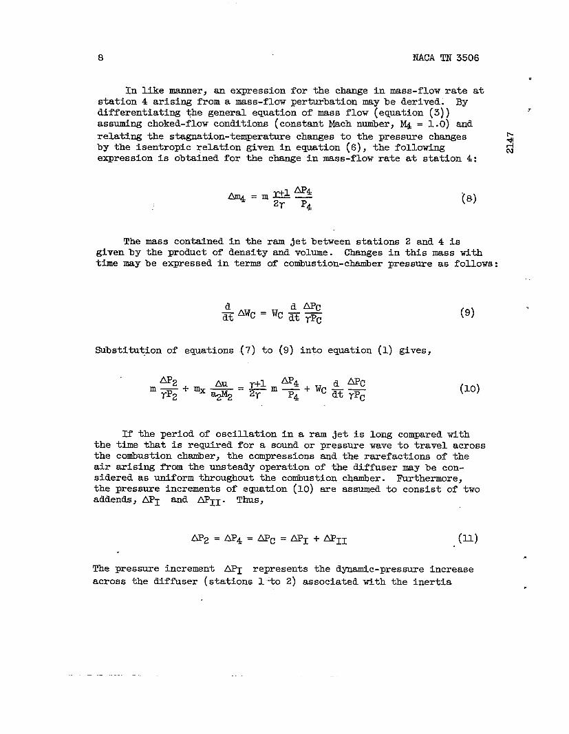
In like manner, an expressionstation 4 arising from a mass-flow
NACA TN 3506
u
for the &ange in mass-flow rate atperturbation may be derived. By
differentiating @e general equation of mass flow (equation (3)) 7
assuming choked-flow conditions (constant Mach number, IQ = 1.0) and
relating the stagnation-temperaturechanges to the pressure changes Gby the isentropic relation @v-en in equation (6), the following :
expression is obtained for the change in mass-flow rate at station 4:
(8)
The mass contained in the ram jet between stations 2 and 4 isgivenby the product of density and volume. Changes in this mass withtime naybe expressed in terms of combustion-chaniberpressme as follows:
a q!&AWC ——= ‘c dt rpc (9)
substitution of equations .(7)to (9) into equation (1) gives,
AP2 AP4 d All-Jm yP2 ‘%&=+ mm+wcdt Tpc
.— (10)
If the period of oscillation in a ram jet is long compared withthe time that is required for a sound or pressure wave to travel acrossthe combustion chamber, the compressions and the rarefactions of theair arising from the unsteady operation of the diffuser nay be con-sidered as uniform throughout the cotiustion chamber. Furthermore,the pressure increments of equation (10) are assumed to consist of twoaddends, API ad AP1l. Thus,
AP2=AP4= APc=AP1+AP11 .(U)
The pressure increment ~ represents the dynamic-pressure increaseacross the diffuser (stations 1-% 2) associated with the inertia
.
.

yHc1
NACA TN 3506
properties of the air andpressure incrtient AP~
9
the unsteady operation of the diffuser. Therepresents the pressure change in the ram
jet due to the diffuser-shock ~sition, which changes during theunsteady operation of the diffuser and will be assumed to be givenby the mass-flow change at station 2.
A simple appro~tion of MI may be given by Newton’s law
~1 =
The pressure increment AP~tion as
‘A d Au.——Al dt .
(12)
may be stated according to the assump-
where dY/dm2 is the slope ofequations (7), (lJ_),and (12),
m/hi?\
+&lJ112
the diffuser characteristic. I&amAP~ maybe evaluated as
(13)
By substitution of eq~tions (Xl), (12), and (13a) into equa-tion (10) to eliminate all variables except Au, a second-ord$r,linear differential equation of constant coefficients for the resorlantprocess in a ram jet without conibustionmaybe obtained:
‘- Au-,gM2[&-%:(:)*w]&Au+-WC WA d2
mx TpAl ~
(11 )y+lm dp Au=o-—. —= 2y P dmz (14)
.—_..,______ _____ .— -—

NACA TN 3506
nThe general form of
free-vibration equation:
d.2Kl ‘AU~t2
(See ref. 4, for example.
equation (14) is that of “- --———.--1——.—-—-—zne commowy mown
%“i-lN
- K2 &Au+K3Au=0
) The solutions for thefrequency, respectively, may be written as
%—t2K1
Au=Be[m
tK3K22Cos
~- 2K1
and
(14a)
amplitude and the
7(14b)
where B and Q are constants of integration. Inasmuch as thederivation of eqpation (14) has assumed small amplitudes of oscillationand friction effects have been neglected, equation (14) cannot be usedto predict variations in amplitude with time.
Theoretical stability criterion. - According to equation (14), aram-jet diffuser will deliver air to the combustion chmiber without
pulsation if the coefficient of &Au is positive. Thus, any pressure
disturbance in the system wi.11die exponentially with time. Furthermore,
the diffuser will be unstable if the coefficient of -&Au is negative
and any pressure disturbance in the system will then be amplifiedexponentiallytith time. For the special case when the coefficient of
-&Au equals zero, equation (14) describes a sine-wave oscillation of
constant amplitude.
Examination of equation (14) reveals that the coefficient of & Au .
will be positive or negative accordingly as the term.
.——

NACA TN 3506 I-1
negative, a stable system results. If the value of dP/dJ.n2is”—
()y-l ‘A m a2positive and larger than the term — — — — M2, however, an
2. Wc mx Al
unstable or @sating system is predicted.
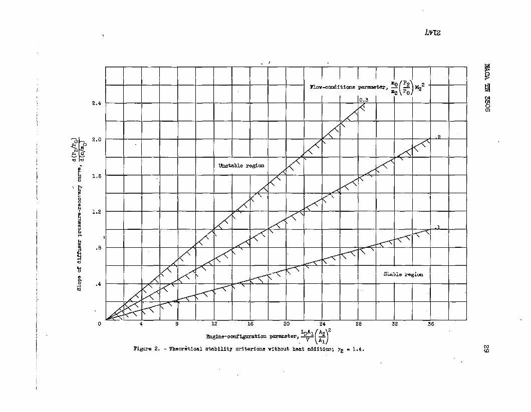
A plot of asented in figure
r
physical interpretation of these criterions is pre-2. The curves of figure 2 are essentially a plot of
1_w
the term() ]
% M2&-%&A~of equation (14) but include some
additional assumptions not made in deriving equation (14). In arri~at the parameters used to plot the curve of figure 2, it was assumedthat the mass of the diffuser air column WA is equivalently given
bY P~l where L is the diffuser length from station 1 to 2. Themass of air contained in the plenw chamber WC was assumed to be given
by eV where V is the sum of the volume between stations 2 and 4 andthe residual volume of the diffuser (total diffuser volume less volumeof air column L&l), which is representative of the portion of thediffuser acting essentially as a storage volume. In addition, the re-sulting parameters have been nondimensionalized.
()
mo P2In figure 2, a curve of a given value of ~ — .22 is the 10CUS
Po
of values of the theoretically maximum positive slope of the diffusercharacteristic as a function of a parameter of the ram-jet geometry
()
L@l A2 2
—qthat may be tolerated before resonant instability occurs.
Q
For example, for a fixed value of the flow-conditions parameter
()
mo P2 ~22—.m2 PO
and a given diffuser characteristic represented by the
slope of the diffuser characteristic, increasing diffuser length orinlet area (for a fixed diffuser-area ratio) or decreasing conibustion-chamber volume tends to increase the stability of the ram jet. In alike manger, other ram-jet design criterions affecting stability arereadily obtained.
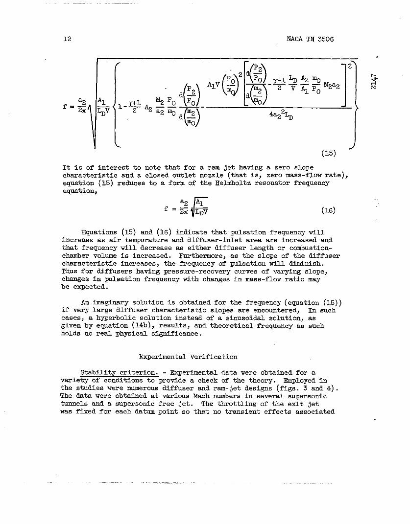
l&equency. - An equation for the pulsation frequency of a ram jetmy be obtained from equation (14c) using the additional assumptionsemployed in the foregoing stability-criterionsanalysis. Thus,
————.——.~.— .._ -—.. _ _____ - ..—— —.—— —
—.
12 NACA TN 3506
%2‘“x %
.
%2Po.—a2 %
o~‘o()/%2%
.
(15)
It iS of interest to note that for a ram jet having a zero slopecharacteristic and a closed outlet nozzle (that is, zero mass-flow rate),equation (15) reduces to a form of the Helmholtz resonator frequencyequation,
r
~ Alf ‘G= (16)
&j-Cu
L.
Equations (15) and (16) indicate that pulsation frequency willincrease as air temperature and diffuser-inlet area are increased andthat frequency will decrease as either diffuser length or combustion-chanibervolume is increased. Furthermore, as the slope of the diffusercharacteristic increases, the frequency of pulsation will diminish.Thus for diffusers having pressure-recovery curves of varying slope,changes in pulsation frequency with changes in mass-flow ratio maybe expected.
An imaginary solution is obtained for the frequency (equation (15))if very large diffuser characteristic slopes are encountered, In suchcases, a hyperbolic solution instead of a sinusoidal solution, asgiven by equation (14b), results, and theoretical frequency as suchholds no real physical significance.
Experimental Verification
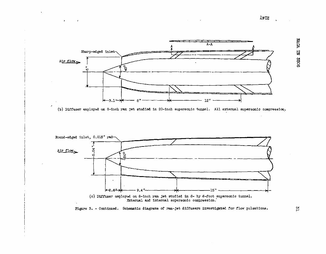
Stability criterion. - Experimental data were obtained for avariety of conditions to provide a check of the theory. ~ployed inthe studies were numerous diffuser and ram-jet designs (figs. 3 and 4).The data were obtained at various Mach numbers in several supersonictunnels and a supersonic free jet. The throttling of the efit jetwas fixed for each datum point so that no transient effects associated
.
—. —

NACA TN 3506 13
.
.
with changes in throttling were included. Pressure fluctuations in theram jet were sensed with commercial diaphra~-type pressure pickups, andrecordings of these pressures were made with a commercial tape recorder.The pressure-pickup frequency measurements were checked with high-speedmovies of the normal-shock oscillations at the diffuser inlets, andexcellent agreement waE obtained in all cases.
One set of experiments provided data (figs. 5 and 6) sho~the effects on diffuser flow pulsations of minor changes in theprojection of the diffuser conical spike of a ram jet at zero attackangle and a given free-stream Mach number. The data were obtained ina MO = 1.77 free jet with a 16-inch ram jet (figs. 3(a) and 4(a))
having a single shock projecting cone with all external compressionand a sharp-edged inlet.
A plot of the diffuser pressure recovery as a function of diffusermass-flow ratio is shown in figure 5. There is reasonable agreementof the theoretical stability criterion with exp&iment. In all caseswhere the slope of the diffuser pressure recovery against mass-flow-ratio curve was negative, no detectable oscillation of diffuser-outletpressures was obtained. At operating conditions where this curve hada positive slope of some magnitude, however, unstable pulsating flowwas obtained.
The data of figure 5 are plotted in figure 6 in accordance withthe stability criterions shown in figure 2. For each tits point, theslope of the diffuser characteristic is plotted as a function ofmass-flow ratio and the stability condition is indicated. As infigure 5, a reasonable agreement of theory with experiment is shown.
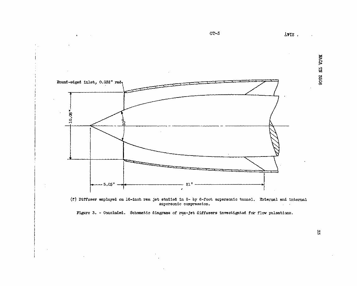
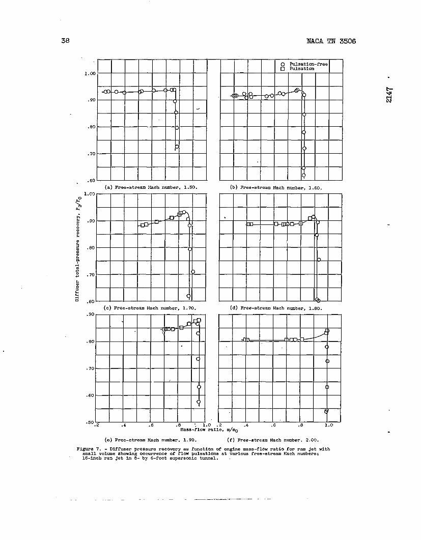
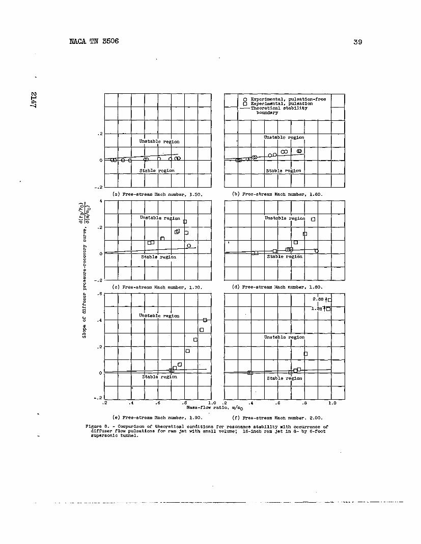
Another investigation was conducted to determine the effects atzero angle of attack (figs. 7 and 8) of a change in free-stream Machnumber (from 1.50 to 2.00) on diffuser flow pulsations for a fixedengine configuration. The study was made in the Lewis 8- by 6-footsupersonic tunnel with a 16-inch ram jet (fig. 4(d)) having a singleshock projecting-cone diffuser with both internal and external com-pression (fig. 3(f)). A rounded-lip diffuser inlet was employed.
As with the data presented in figures 5 and 6, experimental resultsagree reasonably well with theory. A positive slope on the diffusercharacteristic is also necessary for pulsation in this case. At ~
values of 1.50 and 1.60, no pulsation was observed over the mass-flowrange investigated. Pulsation was first observed to occur at ~ of
1.70, but only over a portion of the diffuser curve in the subcriticalflow operating range. Pulsating flow was encountered for all subcritical
-. . _—— —.— --——- .- —— —..————.

14 NACA TN 3506
flow conditions at which data were obtained for ~ values of 1.90
and 2.00. In no case was pulsation observed to occur when the slopeof the diffuser curve was negative.
In order to determine experimentallywhat effect, if any, achange in conibustion-chambervolume would have ont$e pulsing character-istics of a ram jet, the combustion-chambervolume of the 16-inch ramjet just discussed (figs. 4(d) and 3(f)) was increased a~roximately2.3 times. .Figures 9 and 10 present the results of an investigationof this modified ram jet conducted at Mo values of 1.60, 1.80, and2.00. No signific?wt chmges in the stability characteristicswereobserved> except that some pulsation did appear over a sml.1 r~eof subcriticalmass flow at l@ of 1.60; pulsation at an MO of1.60 dld not occur in the investigation with the smaller combustion-*er volume. Again reasonable agreement of the theory with experi-ment was obtained. The significmt changes in pulsation frequency%hat occurredwillbe subsequently discussed.
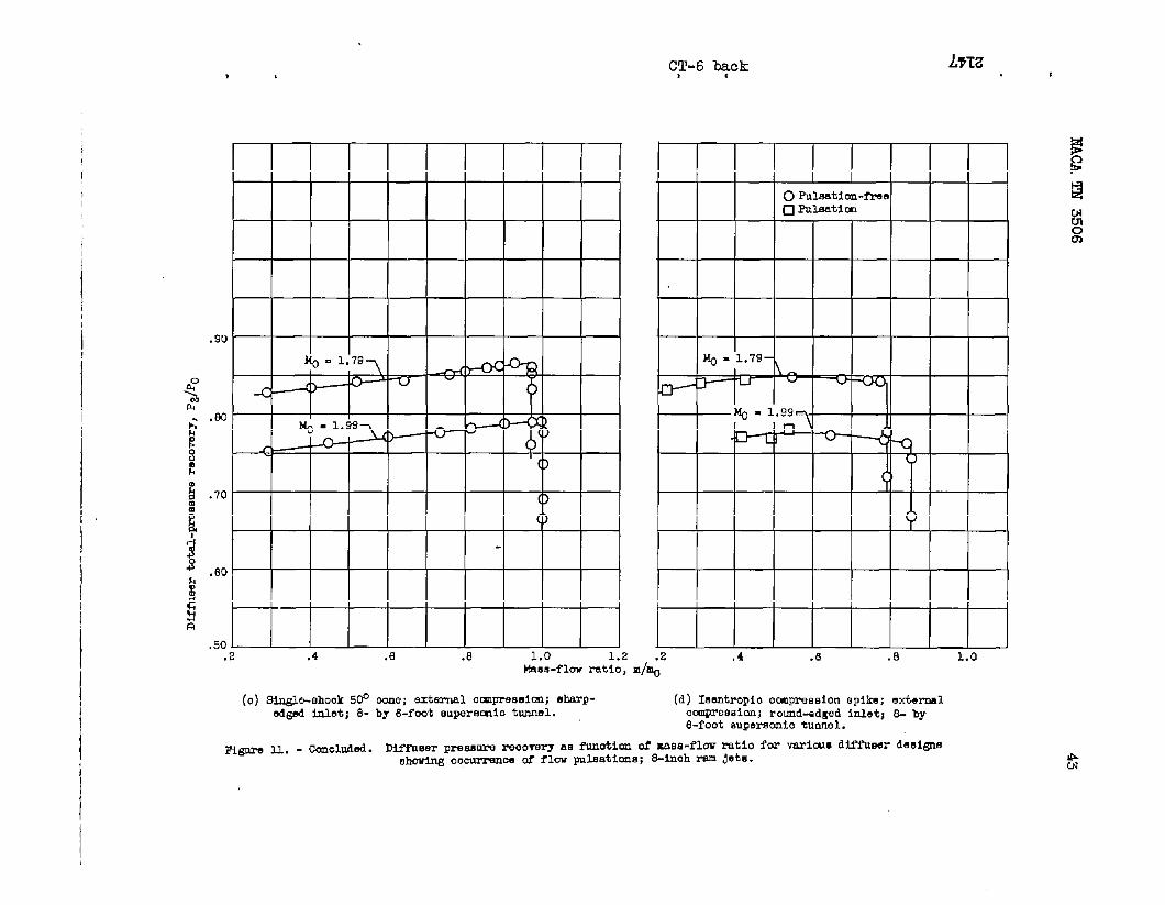
)Flow-pulsation data (figs. 11 W 12) were also obtiined from a
number of experiments on8-inch ram jets (figs. 4(b) and 4(c)), whichshow the effect”pf major ram-jet and diffuser design changes on
.
diffuser flow instability. The ram jets were equipped with diffusershaving (1) an isentiopic compression projecting spike with all externalcompression and a round-edged inlet (fig. 3(d)), (2) a single-shockprojecting cone with all external compression (figs. 3(b) and 3(e)),and (3) a single-shock projecting cone with both internal and externalcompression and around-edged inlet (fig. 3(c)). The data wereobtained in the Lewis 8- by 6-foot supersonic tunnel szd the Lewis20-inch suprsotic tunnel at values of Mo of 1.79 and 1.99 forzero angle of attack.
.
In alJ_cases presented in figures 11 and 12, the same criterionsalready presented, which establish the likely conditions of diffuserflow pulsation, were sgain observed. The data presented in figwes 5to 12 indicate that the theory reasonably predicts the stability ofa ram jet.
Frequency. - Experimental frequency data and the computed frequencycurves (using equation (15)) for three ram jets are presented infigures 13 and 14 as a function of mass-flow ratio. The data.wereobtained at zero angle of attack and cover a range of ftree-streamMach nlmhrfroml .77 to 2.00. The ram-jet and diffuser configurationsare some of those already described and are illustrated in figures 3and 4.
.
..— —— ..

TM 3506 15MwA
showFor the three ram jets studied, the theoretical-frequency curvesgood agreement with experimental.frequencies both as to magnitude
and trend. These data include the effects of changes in diffusercharacteristic,mass-flow ratio, and conibustion-chanibervolume.
FUISATIONWITH CCMMX?TION
Theory
A generalized treatment of the resonance characteristics of ramjets with heat addition is very difficult because no single or fixed~ttern of heat addition exists. By exambition of some special case~,which in some degree approximate the combustion process in ram jets,effects of heat addition on the resonance characteristicsmy beestimated.
As a theoretical example, a case maybe considered where a fuelflowing at a constant rate is burned at constant efficiency. The fuelmay be assumed to burn instantaneously and uniformly at the coribustion-chanber entrance and temperattme changes at the entrance are trans-mitted throughout the combustion chamber in a time that is shokt cowpsred with the period of oscilktion. Thus a uniform temperature T4is assumed to exist throughout the conilmstionchaniber. The temperatureih also considered to increase at a uniform rate with fuel-air ratio.
Before continuing the discussion of the effects of heat additionon the resonance properties of a ram jet, the reasonableness of thetemperature time-lag effects should be briefly analyzed. If the timelag of teqerature, due to fluid transport from station 2 to station 4,is approximately given by
t+
+2TM2
then for low values of M2 the assumption of uniform temperature through-
out the cotiustion chaniberis a ~or one fo$ quantitative analyses. Ifthe value of M2 is relatively high (say, M2 = 0.25 and T = 4.O),
the rate of fluid transport is of the order of the rate of sound
~~tion ~ cold ah; tie asmtion of constant temperature through-out the combustion chaniberwould then be as valid as the constant-pressure assumption in the case witha&t combustion. Under this
/
——. —. ———... — .—. -.z —— _
16 NACA TN 3506
condition, however, the velocity of the fluid in the combustion.
chaniberapproaches the velocity of sound. The validity of theassumption of constant pressure throughout the cotiustion chamber %.
and the neglect of inertia forces are questionable. The analysis G
would again be e~ected to give only qualitative trends.
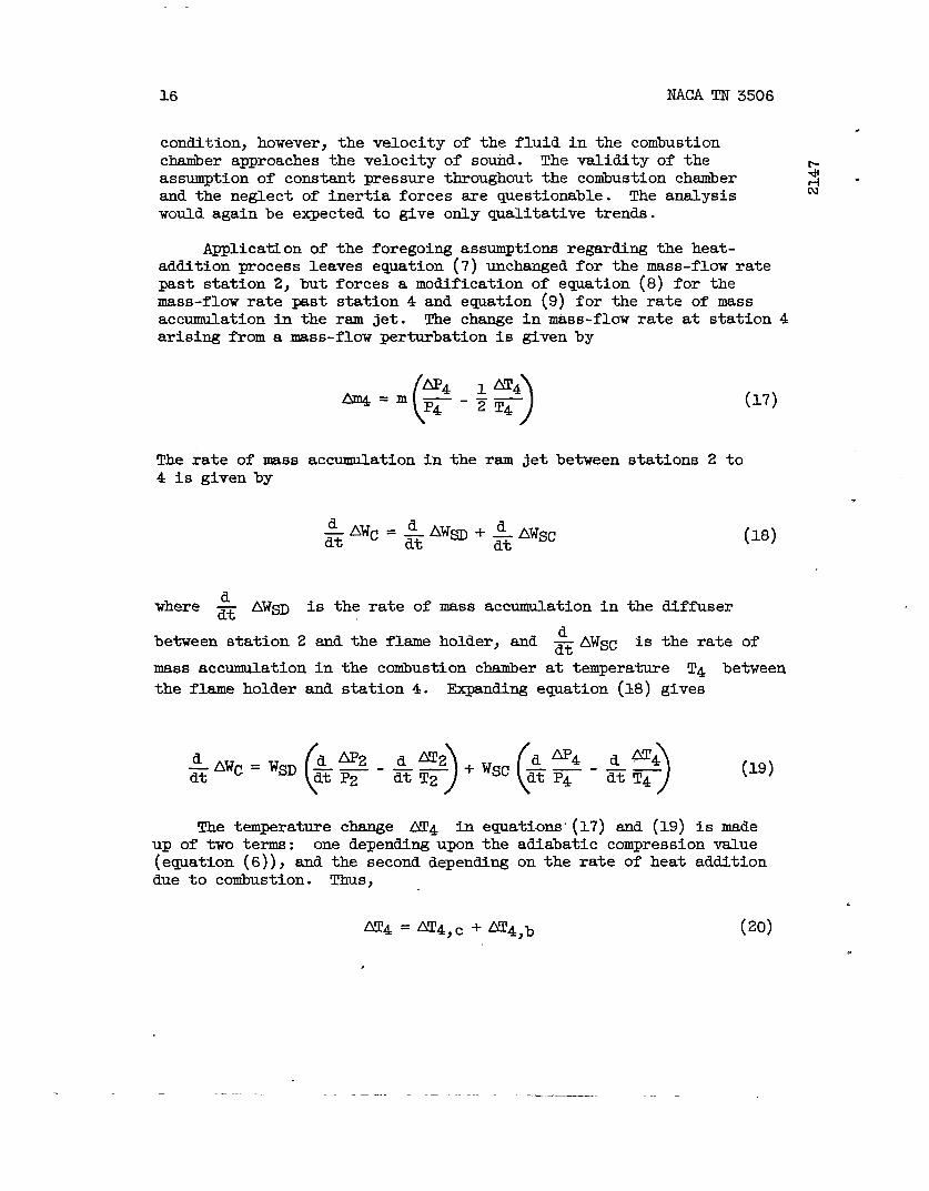
Application of the foregoing assumptions regarding the heat-addition process leaves equation (7) unchanged for the mass-flow ratepast station 2, but forces a modification of equation (8) for themass-flow rate past station 4 and equation (9) for the rate of massaccumulation in the ram jet. The change in-s-flow rate at station 4arising from a mass-flow perturbation is given by
The rate of mass4 is given by
accumulation in the ram jet between stations 2 to
is the rate of mass accumulation in the diffuser
(17)
.
(18)
between station 2 and the flame holder, and -&AWSC is the rate of
mass accumulation in the combustion chamber at temperature T4 between
the flame holder and station 4. _fing e~ation (18) gives
(d AP2‘AWC=W~ ——
)(
d ‘4
)
d ~4d~< +Wsc ~z-——E dt P2 ‘~T2 dt T4
(19)
The temperature change AT4 in equations-(17) and (19) is madeup of two terms: one depending upon the adiabatic compression value(equation (6)), and the second depending on the rate of heat additiondue to combustion. Thus,
.
Ar4 = ~4,c +~4,b (20)
./

NACA TN 3506 17
In line with the assumptions concerning the combustion process, thetemperature change at station 2 due to cotiustion has a value given by
( )-m2cp T4-T2=
and for a “constaatvalue of fuel flow
oAm2 T4 -T2 +m2
~H ~ (21)
and combustion efficiency>
~4,b = O
(22)~4,b ()“. : Aq
~=- 1 T T
where T is the stagnation temperature ratio.
Similarly, the pressure change ~4 in equations (17) and (19)
is made up of the pressure increments API and AP1l (previously
defined) and theto the change in
change in pressure across the conibustionchamber duetemperature arising from the addition of heat. Thus,
AP4 = AP1+API~+~ (23) -
In evaluating the pressure increment ~, the drop in pressure, across the combustion chamber due to heat addition is approximatelygiven by (ref. 7)
P2-P4 ?-$4,22T41
()
_~_—. -P2 “2 T!2
or differentiating,
.
~ = *’ (T-1) [+($=)+2+ (2.)
— —--

. .
18 NACA TN 3506
Application of the approximate relation
T4M22
~ = cons-t
presented ‘inreference 7 for choked steady-flow ram jets allowsthe quantity AM2/M2 to be evaluated. From equations (20), (22),and (6),
Ar4
()
-M*, * %+9T4 = Tm ?-4 P2 P2
By combinationthe conibustion
with equations (6) and (24), the pressure drop acrosszone becomes
Apt)E&(.-l)
—=P2 T2(T4-1)M22
1-2T4
Froma simultaneous solution of equations (l), (6), (7), (17), and(19) using the proper values of AP and AT given in the foregoingdiscussion, a second-order linear differential eqya.tionfor theresonant process in a ram jet with combustion may befor ram jets having a combustion process such that atemperature is obtained from an increase in fuel-airequation is
() d2Au‘A B+~__P2A1 T2 dt2
obtained. Thusrise in combustionratio, the resonance
(25)
.
—. ——.—— —— —-

NAC!ATN 3506
where
r2M#’w~ ~(T-1)
B= ~+wc+wcT2(T4-
1- 1)M22ZT4
{
E= 1+
and,
.
L
(T -1) WC
-.., ,!,*,,.. ,,
(’1-.yz-1
T2(T-1]+ T*-1 )y4(Gl) -
/ yz-1 y4-1
1-7J=T+FJ-m ~-~+~_]T2(T4-1)M22 T2(2-1)
\1-
2Y4/
D=Wc
(
T -1
)
T##(T.+—-T2(T4-1)M22 T 2T
1-2r4
T$22-(T-1} T-1 y2-1
mj~
T2(Y4-1)M2Z - z ~ T2(T4-1)M21- “~)
1-2T4 2Y4
T-1
-ii-[ 1]
yz-11-
T2(T-1)
J
(T-1) (1-Y2M22)F=
[ 1y&-1)M22T21-
2Y4
.
.
--
.—.— —.— ——..—..— .— __.——
20 NACA TN 3506
andThe solution of equatio~ (25) is representedby equations (14b)
.
(14C). b+!
Theoretical stability criterion. - As with equation (14), equa-$-
tion (25) offers certain criterions that establish the resonance. .characteristics of a ram jet with cotiustion. Again, a ram-jet diffuserwill be stable or unstable accordingly as the coefficient of
~Au is psitive or negative. The stability criterions me there-
fore given by equating the coefficient to zero. For illustrative
purposes, the quantitiesm— I@, and WA will be evaluated as indmz’
the case without heat addition. In addition, the values of T4 = 72 -
0.03(7-1) snd T2
Equating the.
= 1.4 have been assumed.
coefficient of d Au to zero leads to the relationx
where Q, R, and S sre $’unctionsof only M2 and T and are given as
T2R=— WCT D
Y-*2s =
[ 11- (T2E + F)
()
T2
T2-1 z T2-11+ yM2
-. —— .-——

NACA !13?3506
The quantitiesOf M2 from O
21
Q, R, and S have been graphed in figure 15 for valuesto 1.0 and values of ~ (T4/T2) from 1 to 10.
As for the case without combustion, the physical quantities
comprising the coefficient of d Au are combined in parametricz
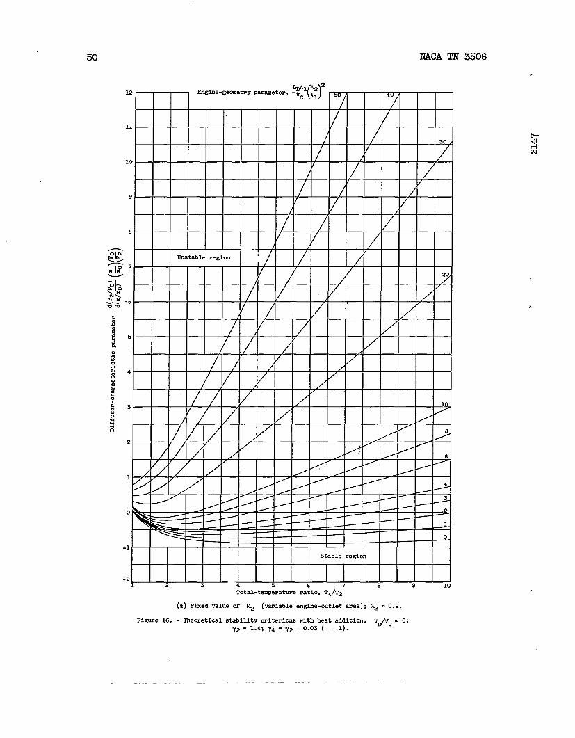
form to show the ef$ect of engine geometry and heat addition on thestability characteristics of any given diffuser. Plotted 4 figuresfigures 16(a) and 16(b) are these stability criterions for a fixedvalue of M2 (variable engine-outlet area) and for a fixed value ofM2fi (fixed engine-outlet area), respectively.
As for the case with no heat addition, a curve of a constant engine-geometry parameter is the locus of the maximum values of the theoreticalslope function at any mean total-temperature ratio across the enginethat maybe tolerated before resonant instability occurs. Thus ramjets with small values of the engine-geometry parameter tend to becomeresonantly less stable with increased heat addition; whereas ram jetswith very large values of the engine-geometry parameter tend to improvetheir resonant stability properties with increased heat addition. Forexample, shortening a ram-jet combustion chamber tends to improve theresonant stability properties. The same improvement in resonancestdbility might also be achieved by lengthening the diffuser. Mostcurrently used ram jets have very low values of the geometry parameter. ‘
Frequency. , Estimation of pulsation frequency is obtained fromequation (14c). As in the case without heatadditionj pulsationamplitude cannotbe determined from equation (25). -
Experimental Verification
Stability criterion. - Because of lack of experimental data, anexhaustive quantitative check of the theory has not as yet been made;however, some experimental data were available for an approximatequalitative check of the theoretical trends. Conibustione~erimentswere conducted in which diffuser-pulsation data were obtained with a16-inch-diameter ram jet in a supersonic free jet and employing aburner using two different fuels, gasoline and a blend of 75-percentkerosene and 25-percent propylene oxide. Data were obtained at Movalues of 1.58 andl.77. The ram jet and burner are shown infigures 4(a) and 17, respectively. The burner employed a commercialspray-nozzle system injecting fuel in an upstream direction 18 inchesahead of the flame holder. The flame .holderwas mounted at the outletof a vortex-type pilot burner forming the end of the ram-jet diffuser
——... -——

22 NACA TN 3506
center body. The same pr’essurepickup and recording instruments wereused for pressure-fluctuationmeasurement as previously describedfor the case without conibustion.
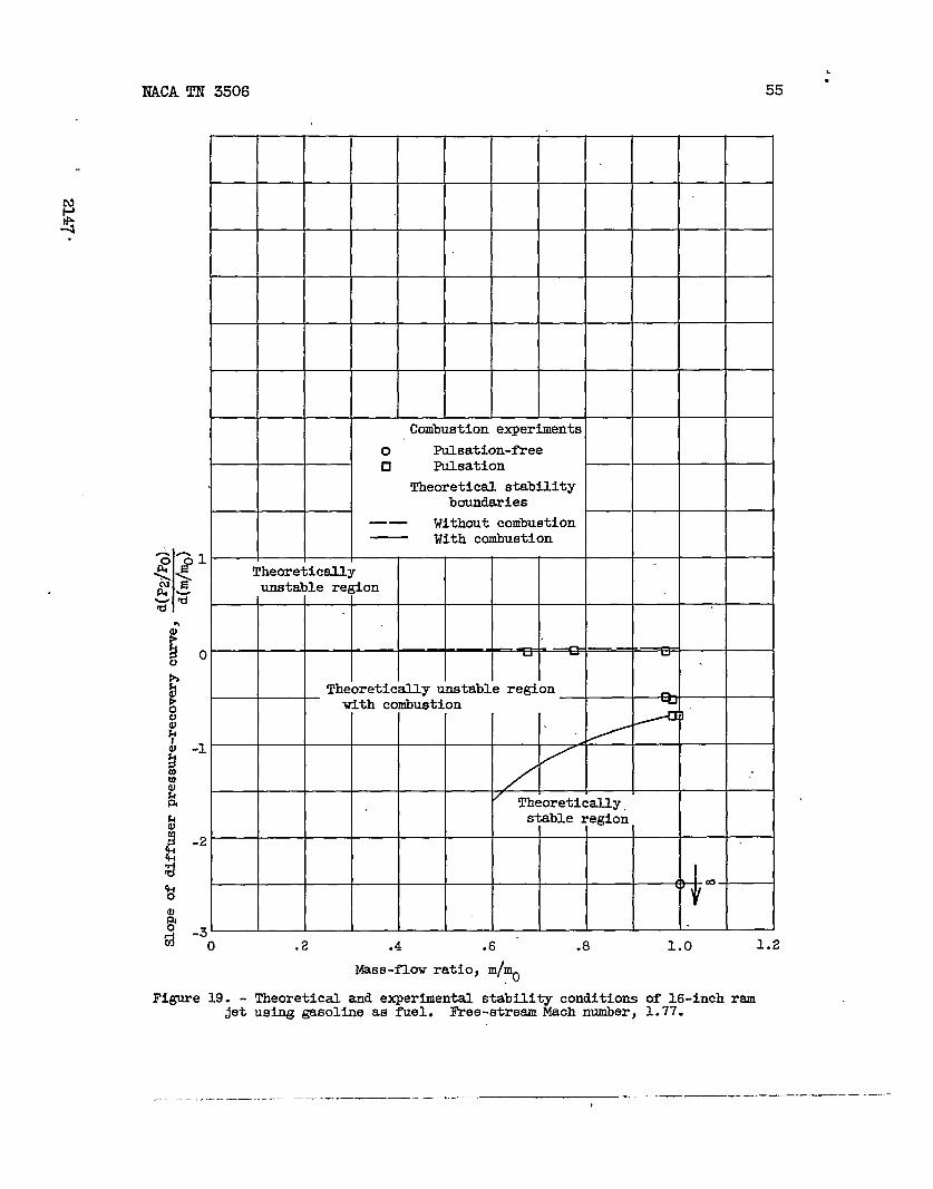
The results of the experiments using gasolime are presented infigures 18 to 20 where plots of diffuser pressure recovery as afunction of mass-flow ratio (fig. 18), the slopes of the pressure-recovery curve as a function of mass-flow ratio (fig. 19), and tracesof the pressure fluctuations for representative data points (fig. 20)are shown. The data points of figure 18 are noted with nunibersthatcorrespond to those numbers in figure 20 to show correspondingpressure traces. A comparison of the data obtained with and withoutconibustionshow that in both cases for supercritical operation of thediffuser, pulsation-free flow was obtained in the ram jet. For the casewith heat addition, -sating flow was obtained over the entiresubcritical operating range where pulsation-free flow had been obtainedwith no heat addition. The design of this ram’jet was such that anincrease in heat addition mwkedly decreased its theoretical resonancestability properties in the subcritical operating range. (See fig. 19.)All the data of figure 18 indicating unstable operation are theoreti-cally predicted to be unstible by *tie of the resonance propertiesof the engine) as shown in figure 19.
Flow-pulsation data obtained tith_+he same engine and burnerconfiguration using the kerosene - propylene oxide fuel blend arepresented in figures 21 to 23. The change in fuel caused a pressurepulsation ~esumed to arise from the combustion process that persistedover the entire subcritical and supercritical mass-flow rauge. Theinfluence of diffuser flow pulsations evidenced’by the largeramplitudescan be noted over the entire range of subcritical flows. (See fig. 23.)In this case, resonances associated with the combustion process haveoccurred that are not predicted by the -simplifiedtheory included herein.
●
,ltrequency.- From the pressure fluctuation traces of figures 20and 23, it can be seen that a tide range of frequencies will occur withcodm.stion h the ram jet, Rough esthates of the main frequencycomponents were obtained from these pressure-time traces. The lowest’value of the measured frequency was about twice the theoretical funda-mental frequency (approximately10 cps) computed from equation (14c).
This trend of higher values for the experimental.frequency couldhave been anticipated. In the theoretical model, without cotiustion,the inertia terms arose from those portions of the flow where thevelocity was highest (that is, in the diffuser). In the case with ‘conibustion,high gas velocities also occur downstream of the flame
It
,..

.
NACA TN 3506 23
holder; the gas in the combustion chamber would then be expected toexert large inertia effects that were neglected in the theory. Thecombustion chmiber then serves more as an oscillating piston andless as a storage volume. As a rough estimate, the correspmxiing
frequency should be increased in the proportion
*
VD + VC
VD*3.
CONTROLLING FLOW PULSATIONS
Consideration of the criterions presented herein yields a nuniberof feasible schemes for preventing or avoiding resonantly amplifiedflow pulsations. Presented in figure 24 is a graphic picture of someram-jet design trends that would improve the resonamce stability ofa rm jet having the previously assumed cotiustion characteristicsemployed in obbining the theoretical curves of figure 16. (Variableengine-outlet area to yield constant average M2 with changing valuesof ~.)
Configuration 1 in figure 24 is typical of present-day ram jetsand shows a decrease in resonance stability with heat addition to atemperature ratio of about 3.0. Further increases in heat additionshow an increase in resonance stability, but the degree of stabilitythat was obtained without heat addition is not realized until tempera-ture ratios greater than 8.0 are reached. Configuration 2 shows thatsome improvement in resonance stability is obtained by decreasing thecombustion-chambervolume (in this case, halving the conibustion-chanlberlength). The’resonsmce stability of the ram jet is still less withheat addition, however, than with no heat addition to a temperature .ratio of 4.5. If the co~ustion chamber of configuration 2 represents ‘a practical limit for obtaining reasonable combustion efficiencies,further improvements maybe obtained by iticreasingthe diffuser length.This increase is made for configuration 3. For configuration 3, amarked improvement in resonance stability occurs with increased heataddition. Configuration 4 is an example of the etiremes a ram-jetdesign would have to approach in realizing further improvements in .resonance stability properties.
Only trends are represented by figure 24 and absolute quantitativevalues may not be.correct. This condition holds especially for extremecases such as configuration 4, for it would not be expected to properlysatisfy basic assumptions made in the analysis. In addition, theetireme ram-jet designs indicated may not be practical engine configu-rations when other imprtant factors of design are considered. Also,as previously noted, if a combustion or heat-addition process that
- .—. ..—_. .———z _____ .— ——— A

24
yielded a decrease in combustion-chanibertemperaturefuel-air ratio (for example, rich-mixture operation)the trends shown would be reversed.
NACA TN 3506
.
With increasedhad been assumed, ~
~.. .N
The resonce properties of a ram jet are also affected by thediffuser design. A diffuser characteristic canbe appreciably alteredby changes in the contour of the projecting spike and inlet lip(refs. 8 to 10) by changes in the projection of the spike ahead ofthe inlet lip or by boundary-layer control on the spike.
Under certain conditions of flight, operation of the diffuser atmass flows where pulsations would be encountered as indicated by thepoint A on figure 25(a) maybe unavoidable. In such a case, it ispossible to operate the diffuser at the mass-flow rate B and bypassthe mass-flow difference E - A to the atisphere through a combustion-chanibercooling passage or an air-turbine drive for engine accessories.Of course, the amount of permissible bypass sir might be restrictedbecause of considerations other than the internal flow.
Still another pssible method of pulsation control is to throttlewith the diffuser-inlet lip, as indicated in figure 25(b). A seriesof the throttled-diffuser curvps are obtained with different settingsof the diffuser-inlet area. Thus operation at reduced mass flows an~high diffuser pressure recoveries without pulsation are attainable.A serious disadvantage of this throttling method lies in possibleincreased external aerodynamic tiag at inlet-lip settings other thanthe design point.
A diffuser pulsation can l&ewise be canceled with another puls-ation of equal magnitude and frequency exactly 180° out of phase.Two possille controlJ-ed-pulsationsources are the ccmibustionprocessand the nozzle-outlet area. By alternately increasing and decreasingT or decreasing and increasing nozzle-outlet area, the combustion-chamber-inlet pressure can be alternately increased smd decreased.Such a controlled pressure pulsation canbe adjusted so as to eliminateor minimize any diffuser pulsation. A pressure-sensing mechanism maybe devised to obtain a controlled oscillation of engine fuel flow, ifT is to be varied, or to obtain a controlled oscillation of a nozzle-outlet flapper valve or spoiler, if nozzle-outlet area is to be varied.Because of the inherent inertia in such a system, these schemes maybe limited to the control of only the relatively low frequencypulsations.
Another method of dampingby the addition of a resonator
pressure oscillation isto the primary system.
accomplishedIn.the case of
.
I?ACATN 3506 25
.
an ordinary pipe with standing waves, suppression is accomplished byadding a branch pipe having a natural frequency of that of the primarypipe. (See fig. 25(c).) It is conceivable that employment of aproperly tuned resonator attached to a ram jet could successfullydamp out or minimize diffuser flow pulsation of a limited frequencyrange. The main disadvantage of this system as applied to a flightengine may be that an excessively large damping-resonatorvolume wouldbe required for effective damping.
Diffuser air-column pulsations may also be minimizedby increasingthe resistance to pulsation in the diffuser. This minimization mightbe accomplished, for example, by the addition of a series of screensin the diffuser or by increasing the aerodynamic drag of the flameholder. The desirability of this method of damping is governed, ofcourse, by the magnitude of pressure loss sustained over the requirednumber of screens or other damping resistances for effective damping.
SUMMARY OF RESJLTS
lKroma theoretical and experiment&1.study of ram-jet flow pulsa-tions, the following results were obtained:
1. Application of a Helmholtz resonator concept to the ram-jetflow pulsation phenmenon yielded criterions for determining theresonance stability of ram jets. Briefly, the theory indicated thatfor the case without conibustion,any flow disturbance will be ampli-fied if the curve of diffuser pressure recovery as a function of enginemass flow has a positive slope of some.magnitude. At operatingconditions where the slope of this curve was less than this criticalvalue, the ram jet was resonantly stable. For the case with combustionin the ram jet, the rate of heat addition has an important effect inthat the ram-jet resonance’properties are markedly and complexly altered.
2. For the case without combustion, the theoretical resonancecriterions were found experimentally to reasonably predict theoccurrence of flow pulsations.
3. For the case with combustion, it was found experimentally forone engine configurationusing two fuels that flow pulsations wereobtained at flow conditions for which pulsation-free flow was obtainedwithout combustion. The occurrence of these pulsations with heataddition was theoretically predicted by use of the resonance propertiesof the engine.

26 NACA TN 3506
4. Without combustion in the ram jet, the theoretical frequencychecked the eqerfmental frequency reasonably well.both as to magnitudeand trend. In no case with conibustionwas the theoretical frequencyobservedj the lowest value of the measured frequency was approximately ~
twice the theoretical fundamental frequency. w
CONCLUDING REMARKS
The results of this study offer considerable evidence that ram-jet diffuser flow pulsations, commonly referred to as a %uzz”phenomenon, are governed by acoustical resonance laws. It can beconcluded that the acoustical resonance properties of ram jets are animportant factor in establishing the frequency of diffuser flow pulsa-tions. Also, evidence exists suggesting that the amplitude of a flowpulsation is in some measure affectedly the resonance properties ofthe engine. In addition, significant ram-jet design factors that maybe important in successfully eliminating or controlM.ng ram-jet flowinstability are suggestedby the resonance theory.
Lewis Flight Propulsion Laboratory,National Advisory Committee for Aeronautics,
Cleveland, Ohio, March 14, 1951.
REFERENCES ,
1. Connors, James F.: Effect of Ram-Jet Pressure Pulsations onSupersonic-DiffuserPerToAce. NACA RM E50H22, 1950.
2. F’erri,Antonio, and Nucci, Louis M.: The Ori@n of AerodynamicInstability of supersonic Inlets at Subcritical Conditiom. NACABML50K30, 1951.
3. Fenn, J. B., Forney, H. B., and Garmon, R. C.: Burners for SupersonicRam-Jets. Ind. and Eng. Chem., vol. 43, no. 7, July 1951, pp.1663-1671.
4. Den Hartog, J. P.: Mechanical.Vibrations. Second cd., McGraw-Hild.Book Co., Inc., 1940, p. 332.
5. Heath, W. R., and Elliot, W. R.: Control and Prediction of Pulsa-tion Frequency in a Duct System. Jour. Appl. Mech., vol. I-3,no. 4,Dec. 1946, pp. A291-A293. .
.
—
J NACA TN 3506 27”
.
6. Pearce, R. B.: Causes and Control of PowerPlant Surge. AviationWeek, vol. 52, no. 3, Jsm. 16, 1950, Pp. 21-25.
7. Perchonok, Eugene, Sterbentz, William H., and Moore, Stanley H.:Indirect Methods for Obtaining Ram-Jet -uSt-Gas TemperatureApplied to Fuel-Metering Control. NACA RME7H27, 1948.
8. Moeckel, W. E., Connors, J. F., and Schroeder, A. H.: Investigationof Shock Diffusers at Mach Number 1.85. I - Projecting Single- .Shock Cones. NACA RME6K27, 1947.
9. Moeckel, W. E., Connors, J. F., and Schroeder, A. H.: Investigationof Shock Diffusers at Mach lhniber1.85. II - Projecting Double-Shock Cones. NACARME6LI.3, 1947.
10. Moeckel, W. E., and Connors, J. F.: Investigation of Shock Diffusersat Mach Number 1.85. III - Multiple-Shock and Curved-ContourProjecting Cones. NACARME7F13, 1947.
.
“
._.———. —-— —-. .— ..——— ——

v, volume
(a) EaQholtzresonata.
- holder
Al, m V, volrme
1 2
(b)Bsm jet with diffoeercontiin~ no centerbcdy.
? holder
\ \\x
1- --lAlrcolulml, II1 2 3 4
(c) Eam jet vlth dlfYusercontalnhg centerbdy.
?lgure 1. - go-tic a~ d mmhOm resonator ma rem jets .dmim3 Pi@on-like ah colms.
.—-.. — .—. ---
.Lm.?
2.4
I
i
I
0
,
0.3
\
Vnstabl.e region
A Af ~
<
(’
,-/
\
\1
3\
/ /
\ -I’
< KA -.
\ Stable re@ca\
4’
/\
p
\
4 B 1.2 16 20 24 28 32 S6
.()L-#l AZ2
Ihgim-oOuf@tim *or, ~ ~
Pi&.u’e 2. - Theorhlml etabilitr oriteriond withmt heat additicm; 72 * 1.4. NCo
I

Sharp-edged Met, 0.004” rad
u
tm
%+
Y
i
(a) Diffuser employed on 16-inoh ran Jet atudi~ in supersonic free Jet. All ertermal Eupersonio ounpmf3sion.
Figwe 3. - Schematic iiiagrems of ram-jet diffueera Investigated for flow puleaticm. @
9
2147
AA-A
$., . .Wmm. edd *nl.+-
(b) Diffuser employal on 8-inohmm jet atudld ti 20-inch EIupermnio twmel. All external eupmemio ocmpmeslm.
Ronnd-edgd inlet, 0.0L5 “
a
Air flov>*m
d
(o) Diffuser employed on 8-inch ram Jet etudled in 8- by 6-fOOt :uperscmio tunnel.
External and inteme.1. superacmic oampr.mim.
Fllyce 3. - Cuntmd . %hmtio diogmme of mm-jet diffueere Imwtigated for flow pulestim.
!3
!4m
wr
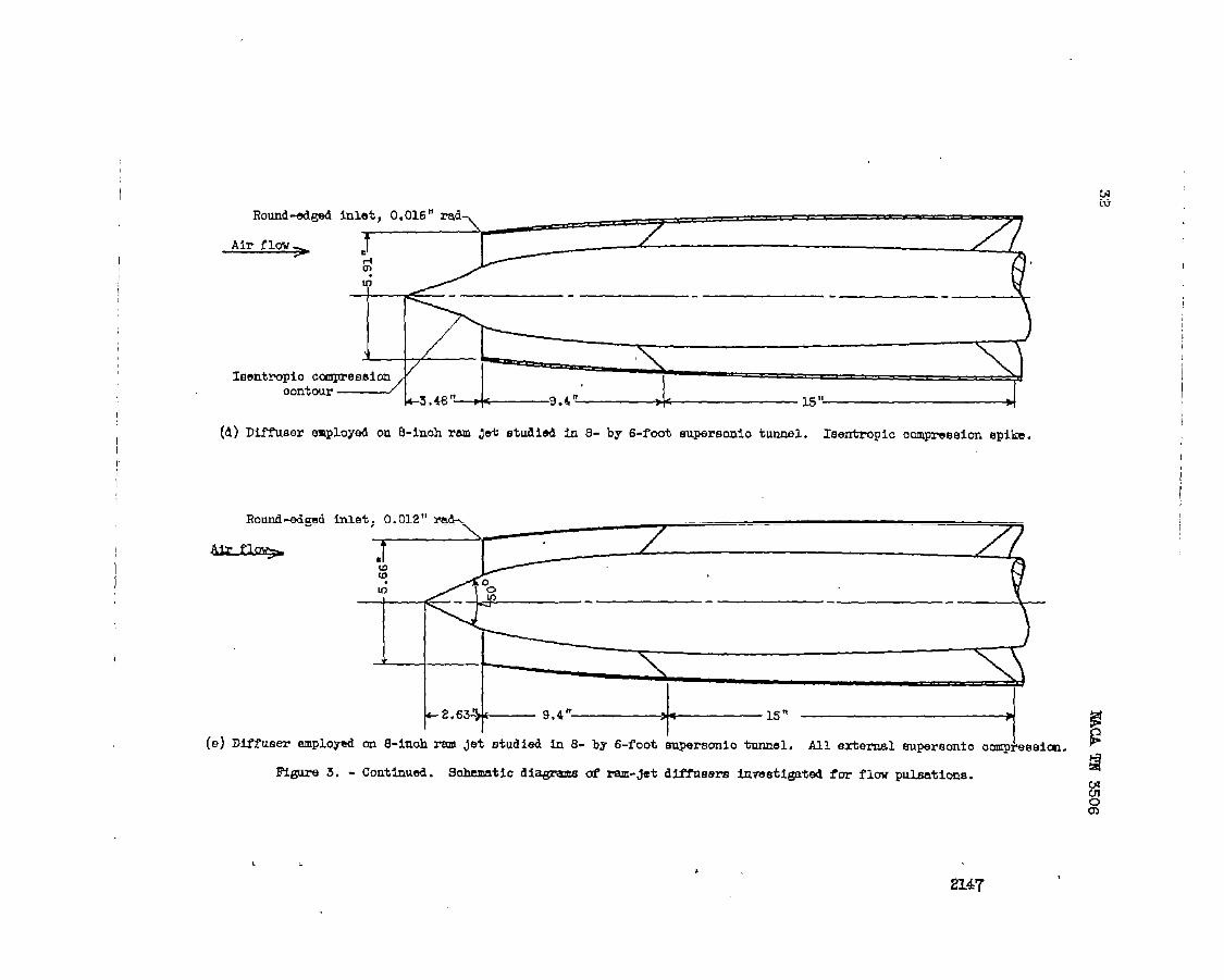
Round-d@
Air flew+
inlet, 0.016” rad
+~””’ ‘“~ ‘“”””””’””’”””---”””””77.-lm
M- - - --+w \~-...\(Ieentrqio ocmpresslon I
(d)
‘ontw~ L3.4%”4-9.4”’ Ll.s~
Diffuser .employ&l on 8-inoh ram Jet studied io 8- by B-foot eupersonlo tnnnel. Isentmpic OOmprWMIOU epib.
=“”dMe’~G
(e) DiYfueer employed on E-inoh rem jet studied h 8- by 6-foot kpersonio tunnel. All external euperaonto
Fl@lre 5. - Continu6d. Sohrmatic diagreme af ram.&t. diffwera inwetigatd for flow pal.eatione.
Iompreeeim.
L .
2147
CT-5
I
1
J
\
t!
Emnd-dgea inlet, 0.052”
b
o“l-l
(f) Diffuser mployed on 16-inoh ram Jet studied in 8- by 6-foot aupereonic tunnel, Exterml and inti?.mal
supersonic umpreaBion. ,?
FZgure 3. - cmOhidOa. 6ohematlo diagram of ~-jet diffueerm Invwtigatea for f lW puleatiana.
Ct4r-x

\
,Al - 0,375 q ft
(a) 16-inch ram-jut engine (diffuser illnatratei in fig. 3(a)) emplo~d in free-jet experiments.
? . 1.717 m N,
~ . Z.eBfi
J++---7”87
Al . 0.1096 6q ft
Air+ A*< k
o
r< ‘
6
t
(b) E1-inoh ram-jet eaglme (dfieer ilMatrmted in f lg. 3 (b)) employed in 20-tioh ‘supersonic tanmel experiments.
Fi@re 4. - %hemtio diagmmm of ram-jet ccmfiguratimm used In dlffnwr imeutigationm.

, CT+ back LFE! ‘
4
A~direotkm
P=o. wauft~-2.67ft ‘
(p) e-inch Em-Jet _ (4MfuEeI’E fm+=+ed h fi~. 3(0), 3(d), @ 3(e)) ~PloYed in@- by 6-fret Engawonio-tunnel experhnts.
Alr-flew tbrottliim+ *flw t&OttM.n&
valve looation fw valve locatim fOr
mall ?’olIme lmge Volwm
I
!-= ‘.” ~V = 5.40 OU.ft (~ VOhlMO) end 12.4 Ctl ft (lam volume)
~ -9.17 ft
Al = 0.4@3 w ft
(d) 16-inoh ram-Jet engine (diffuser llluBtrated in fig. 3(f)) emplopd in 8- by S-foot
euperacuio-tnnnel experiments.
Figure 4,. - Cmoluded . &hemtio diagrem of ram-@t. oonfiguraticaw used in diffmer Inveeti@tiono.

-.. .0 IW.e-dion-free
O Ful.cation
.9sI I 1
k(a) spike Pr@otim, 4,18 in0h9s.
u
“’O_tttmtn.74 I I I I I I I (..-
.3 .4 .6 .8 .7 .e .9 1.0 1.1
(b) Spiko proJectim, 4.22 Inohea.
.3 .4 ..5 .6 .7 .8 .9 1.0 1.1
Masa-flw ratio, I&
(o) Spike proJeatim, 4.27 imhea. (d) 6@ke pru@otim, 4.3E tikS.
F@lW 5. - IMflwm prmmre recomv M fnnntton d [email protected] mmm-flmv ratio far mwiom dlffmai-
Uplke pm@bialS ehm-lng Calditim for Oomrrenrm of flcu pnlnatiarm; 16-fnnh ram Jet in
enpermmlo free jet at ~ - 1.77.
2147
i
!$

NACA TN 3506 37
.
.
.
0 Experimental,plllsation-freeCl EXpOtient~, pUISation— ~eoretloalstability
boundary
..40 ~
L
&o
LJP5NR%@
.20- Uiwtableregion
!!
noc
o
g 8
k I u u n o~“
w
4
~
o
P 20
-.h Stableregion
3 0
?l@ CX3 ()~
4mc )
-.@& mo o
l-lm
-.60 .2 .4 .6 .8 1.0 1.2
Maas-flowratio,m/~
Figure6. - Comparisonof theoreticalconditionsfor resonancestabilitywith -“ occurrenceof diffuserflowpulsations;16-inchrem jet in supe=onicfreejetat free-streamMachnumberof 1.77.
----- —.—.—____ _ _ .———— — -.
38 NACA TN 3506
1.00
m -o LJ 1 ? -c)-m.s0 LJ
i-1
.80 d
3
.70
.60
(a) Fraa-stream Uach number, 1.50. (b) Free-stream Mach number, 1.60.
$’”OOUzULLLl UzLLM=U
I I I II In--ml --l
! 80t+tH+tHI I I I I I I II I
(c) Free-stream Mach number, 1.70. (d) Free-stream Hach number, 1.80.
.90
-L.uLtu. c 1
.80 $ n $ TrE Y
c )
c I()
.70
() ()
.60 -
~
&
.50->.4 .6 .8 . 1.0 .2 .4 .6 .8 1.0
was-flow ratio, m/mo
(e) Free-stream Mach number, 1.90. (f) Free-stream Mach number, 2.00.
.
.
Figure 7. - Diffuser pressure recovery as funation of en@ne mass-flow ratio for ram jet withsmall volume showing occurrence of flcw pulsations at various frae-stream Mach numbers;16-irmh ram jet in 8- by 6-foot supersonic tunnel.
—
TWA TN 3506
.2
0
-.2
4
.2
0
-.2
Un8table region
-f33 -CC h (-1 r m
Stable region
(a) Free-stream Mach number, 1.50.
w atable re~ja[3
@ 3
n-ln
o
stable region
(c) Yree-stream Mach number, 1.70.
.6
Unstable regim.4 m
•1
u
.2c1
o
oStable region
-.2..2 .4 .6 .8 1.0
0 Experiumntil, Puhation-free0 ExprWntil, PuM-ation
— — Theoretical atabilltyboundary
Unatable region
m ~
- w -
Stable m gion
(b) Free-straam Mach number, 1.60.
Unata ble region D
[1
, u
r * cStable regicm
(d) Free-8traam 14aohnumber, 1.80.
I2.,88+E
1.28fu
Unstable region
3
Stable re.qOn
.2 .4 .6 .8 1.0Mass-flow ratio, m/mo
(e) Free-stream Mach number, 1.90. (f) Free-stream Maoh number, 2.00.
Figure 8. - Ccmperiaon of theoretical conditions for resonance etability with Occurrence ofdiffuser flow pulaation6 for ram jet with small volume; 16-inoh ram jet in 8- by 6-footmpereonio tunnel.
-- ——-——— ...— —.—— ——— — -— —. —— . ..—

40 NACA TN 3506
.
0 FUMation-free❑ Pulsation
1.00
.90- m -Q- + ‘. F \/
).80
c)()
.70$
2& c):0 .60 20a&
$: .50E .2 .4y
6 El 1.0(a) Free-stream Mach number, 1.60.
l-l .90.;*
(b) Free-stream Flaohnumber, 1.80.
h
i~ .80 n -
n &
.70c
.60(>
.50.2 .4 -6 .8 1.0 1.2
Masa-flow ratio, m\~
(c) Free-stream Mach number, 2.oo.
Fisura 9. - Diffuser pressure recovery aa funation of mase-flow ratio for ram jet withM& volume abawing ocourrenoe or flow pulsations at various free-stream Mach numbers;16-lnah ram jet in .9-by 6-tat @uparmmio tunnel.
J
— .- —

NACA TN
.
o kwrimenw, ml.atf-free
❑ ~m=, pulaatlon— Theoreticalstability
botiexy
.2
Unetable regionu u
o 0
0 — ~~Uo
stable region
!?0
(a) R’ee-dnwam Maoh number, 1.60.
.4
❑
.2Uiletable rqgon
❑
n
t1❑m
i“ — ‘,
iStable region
~
g -.2 AQ-1g (b) Free-streamMach number, 1.80.
i “48+ o. 53 A-, .J 1.1 0m
Unstableragion.2 u
u
o-— —- 1ILJ
stab le region
-.2-0 .2 4 .... a .
I&em-flow ratio, I&.
(c) Free-streemMaoh nombar, 2.00.
Figure Jo.- cmparimm of theoreticalconditionsfor reecaanoe stabilitywith Ooourranoe of MfYnatU’flov pnlaationefor ram jet with largevolume; IS-inchram jet in 8- by 6+%ot supe?x&do tunnel.
. -— -- —.—!

I
1
,
0 PulBaticm-meD FnMatim
~ - l.79–1
Y
c)
()
.2 ,4 .6 .8 1.0
Mm-flov mtio, m/~
(0) Singl+ehcak S@ wine; extend .cqree.im; harp(- d) Imntropio omFI%mion apib; extmmsl
m@ed Met) 8- by .S-foot mperacmio tunnel. o~e@sim~ round-edged inlet, & bye-foot Eqmmonio blmrlel.
Figure ~. - O.XIChUId. m.ffnner Pi-a-m -- a~ @im ti ~Bs-fl~ ~tiO f~ ~- dfi-r desi~
‘9i-c@W 0ocurrenca of flaw pnlaaticm; %Inoh M Jetm. b%CA
II

44 IIAC!A TN 3506
.
?3
O “Experlrnental, puleatlon-free
❑ Erperlmental,pulsation— Theoreticalstability
bouqdary
.2Unstableregion
u3
0 ( 0 0 ~ 0— — — <w 4
c-- — — — n n0
00Stable region
-.
(a) Free-stream Mach number, 1.79.
.
Unstable region
u
o 0 0c 00 c) 00 0 a ) 0(2
o — - — — - — — — — —Q ~ —
o
Stable regiono
0
-.0 .2 .4 .6 .8 1.0
Mase-flow ratio,m/~
(b)I?ree-streamlhchnumber,1.99.
F@Ure 12. - Comparison of theoretical mnditlons for resonamestability with oocwrenoe of diffuser flow pulsations for varlouediffuser desigps: 8-inoh rum .Ietin 8- by 6-foot supersonic tunnel.
J
“
.
— —

.
.
— TheoryO Experiment
m eoreticallystable
20 I* 4 I >
stable I ,
0 c)0
10
o- n .w m n w A
45
~ (a) 16-inch ram jet in supersonic f!reejet at free-strem Maoh number of 1.77.
Mass-flowratio,mimo
(b) 8-inch ram jet In 20-inch supersonic tunnelMach number of 1.98.
Figure13. - ll?ewency of pulsations.
at free-stream
.—— — —— _——

46 NACA TN 3506
..’.-..
‘“\
0 m~% smalJ.-volume ram set
30 0 mrimental, large-volume ram jet
— Theory (equation (1.5))
20 mv
ax )
10
0.
(a) Free-tiream Mach number, 1.8.
20.
c~n \
0>
10.b
0. A
(b) Free-stream Maoh number, 1.9.30
20, q pu c)
❑ C110.
0.2 .4 .6 .8 u
1.0
Mass-flow ratio, m/~
(c) Free-stream Mach number, 2.0.
Figure 14. - Frequency of pulsation at various Mach numbers for 16-inchram jet with two different volumes; 8- by 6-foot supersonic tunnel.
—————— .—

.
I
I
1.4
1.2
1.0
.8
.6
.4
I
.E
o
Ombustion-chmkr rinlet &h number
- 1.0
\
\
\
~
\
I I I I
2 s 4 5 6 7 8 a 10
‘rotal-tmpwdnreratio, !@e
(a) &mbustim-ohmber _atm dblaahnumbe-rpe%, Q
Fi@re 1.6. - Pammdarn for dub.smining tboretiml difitmer sWbility with heat additim.7Z=1.4J 74-7z -0.03 (T-l).
*-J
I

t 2147.

q’r-7 , Lmz , ,
I
1
I
I
50 NK?A TN 3506
12 -e-mmetry parametar,+~y
L@l A2 2~q 40
11 r /
/ 30 /
/
10/
/
/f
/
9 / /
//
/ /
8-
/ /
~ / /
&/
Umtable region
~’ ///
/
/20
~
$26
//
T/
//
i S.
I
/
i /
//
: / /u /~
:4/ ‘ / ‘
/ /
~/ /
/
1~s
10
: / /
~ /n
2 {
/ /
1 /“ / /
4
~ /
o
— — / —
0.
-1Stable reglcm
-22 5 4 5 6 7 8 9 10
Total-temperatureratio, T@2
(a) Fixed value of 1.> (variableengjme-outletarea); ~ = 0.2.
Figure 16. - Theoreticalstabiuty cmiterionawith heat addlticm. v#Vc - 0s72-1-4; Y4-1’2-o.os ( -1).
.
5N
,-,
&
—

51
.
.
6
5
4
3
2
1
0
-1
-2
Engine-gecmetry parameter
+ >2
Umatable reglcm ()cl
-50~ - 50
/ ‘
40.
/ ~— !0
// ‘
//
0
/ / ‘ - -30 36
/ ~
// ‘
7 // ‘
20
~ “m
?~ -
— -—~ ~
108 8
64
Stable regicm
1 2 3 4 5 6 7 8 9 10Totil-teurperatureratio,‘@’2
(b) Fixed value of M2ti (fixed en@ne-outlet area); M@ . 0.36.
Figure 16. - Concluded. Theoretical stability oriterlonn with heat additicm. v#Vc . o; 7’2 = 1.43
I’4-?’2 -0.03 (. - 1).
.
. . . . . ————.————.——— —.. —.-. —

52 NACA TN 3506
—
(a) uptreamvievd corrugated-gutterflameholder.
-17. - E&$et burner.
u

53
.
\
.
.—— -,—-— -
.— ——.C-24142—-. _ ——
(b) E@3y-Ilozzlefwi &eotor.
Flgme 17. - (.kmoluded.Rm-jet burner.
—... . .._. _—— — ..—.. —— -—.. .— ..— —-. - ———

NACA TN 3S06
O Pulsation-free❑ Pulsation
.90
uc
u o
w
.800
e
P7
Lha
$ .70v
:
$
ih
g .90
%n
.80
.70 —o .2 .4 .6 .8 1.0
Maes-flm ratio, m/~
(a) Without combustion.
1.2
.
t-+JN
(b)Withcombustion.
Figure18.- Effectof h-t additiononflowpulsat~o~of 16-tichram jetusing.@soltieas fuel. Free-stream Mach number, 1.77.
.
NACATN 3506 55
..
.
Combustion experiments
o’ Pulsation-freen Pulsation
Theoretical stabilityboundaries
—. Without combustionWith combustion
n n1
< < Theoretically
g $ unstable region
@-
5c1 o
!Theoreticallyunstableregion I-I
o with combustion:y
[ ‘1
alE Theoretically
8
i
-2
ho
#3-.
a -o .2 .4 .6 ‘ .8 1.0 1.2
Mass-flow ratio, m/~
Figure 19. - Theoretical and expertien~ stability conditions of 16-inch ramjet using gasoline as fuel. Free-etream Mach number, 1.77.
—. . ..—--— ....— — ..— -—. - —— — .—..

56 N#LCA!FH 3506
1
1
2
3
5
6
7
—
FigOre20. - PressureOsdlktlm tEUMS in 16-inch rm $et attious mass-flow =t>os using gasollne as fuel. Free-streamMach number, 1.77.
—— -—

NACATN 3506 57
.
1.OC
.90
,80
-40 Combustion pulsations
❑ Diffuser flow and3
rcombustion pulsations
-2c?--
%) 1
Mass-flow ratio, m/~
Figure 21.- Occurrence of flow pulsations in 16-inch rsm Jet using
kerosene - propylene-oxide fuel blend. Free-stream Maoh number, 1.58.
I I I I I
HTheoretical stability boundaries
1 ——— Without combustion
With combustion
I I 1Theoretical.lyunstable region
o — “ - ~ —’Ilm lmrn. -rln
00
Tkoreticel unstable region—
with combustion
-1 0 combustion pulsations0 Diffuser flow and
Oomlxlstionpulsations/
Theoreticallystable region
-2t \ w~
-cl
o .2 .4 .6. .8 1.0 1.2Ma8S-flow ratio, mj~
Figure 22. - Theoretical.and experimental stability condltiona of 16-inch ram Jetusing brosene - propylene-oxide fuel blend. Free-stream Maoh number, 1.58.
.
.- . —. ——. — --—- -—-—.——— .— .-— —— .-— ——

58 NACATN 3506
2
3
4
‘5
6,
,7 ..
..
8“
9,-
Flgore 23. - Rweure osaillatlonta?ao%sin 16-inahram & at varlouemaes-flovratioaudng kerosene- propylen~ide fuel blend. Free-etreemI&sohmnnber,1.58.
— -. —.

4
3
2
1
0
-1
-2
,.(L <.L#l A2 2 Z4
Eqine~metry parfmet.er, — —Vc Al
12
4
\, /
Un.6ta Me r eglon
\
\
\I_
4 3
3
stable region
\
I1
/
7. z A K c! 7 0 .
Totd-tem~~tW ~tfo, T4/T2
Flgllre 24. - k-jet deaigu trends for Improved resonmoe stability.

60 HACA TN 3506
(a) biam-flew mad-off Syatam for ptilsation-fme OparatiQn.
ThrottledcllrYes
lm-~3” <“~s.-Diffm!ertlrrottledlipsettings
-4. l’-IblTrmlCrltlcal-s-flcx Scmliticm
(0) *-PIw rascuww dempiq by mmne of attiohd dm@ng rewn=tw.
Flgllm25. - Rhetratians of ~ methds for o~ Pd.saticn-fmeflowthrcwh ram jete.
__ —z. .— -———-—. .— —-—- —.— ____ .._..