criteria & standards for tactica airfieldl s - … · criteria & standards for tactica...
TRANSCRIPT

• » . , \ ' * *
» « • » / t - T t O / B S
CRITERIA & STANDARDS FOR TACTICAL AIRFIELDS
, - - *
THIRD EDITION
SUPREME HEADQUARTERS AULIEP POWERS EUROPE
DE
CLA
SSIF
IED
- PU
BLI
CLY
DIS
CLO
SED
- P
DN
(201
2)00
08 -
DÉ
CLA
SSIF
IÉ -
MIS
EN
LE
CT
UR
E P
UB
LIQ
UE

SHAPE CRITERIA Atm STAMDARDS TO TACtlfcAL AIRFIELDS
THIRD EDITIOW
Preantbla
1* Tha airfields planned fo>r the use of the tactical air forces ureJar the control of SACEUH have been divided into the following categories î
a. Main Airfields - These are fields for permanent occupation in peacetime. They should have operational facilities to a standard adequate to develop ful l use of their war combat potential. Housing shall be pro-vided by bilateral agreement between the user nation and the host nation.
b. Bedeployment Airfields - These are fields which will not be occupied in their entirety in peacetime by the nation to whom allotted, but which must be immediately available at the outbreak of war for use and occupation by units redeployed from their peacetime locations, Tboy should have substantially the same standards of operational facilities as a main airfield. Peacetime housing accommodation will be provided for a main-terjbr.ce party of IQO »en, The balance of the housing required in peace-time; e.g., for a squadron in rotation, and in wartime for 2,900 personnel will 'ce on a field basis, of Ktiich only essential utilities and canp structures should be provided in peace.
c. Alternative Airfields - These are fields for use as accomnio— dation for wartime reinforcement, for alternative use if main or redeploy-ment airfields are out of action and to give tactical flexibility. The housing accommodation to be provided at these fields will be for a main-tenance party of 50 men.
2, The criteria and standards for tactical air force airfields are presented in this document as follows:
a. Table No. 1 lists the minimum standard facilities to be pro-vided for each particular type of f ield r Facilities desired by a user nation in excess of these standards shall be provided by the user nation or through bilateral agreement with the host government, AU necessary land for stan-dard items and user nation facilities will be provided by the host nation.
b. Appendix A gives details of the required criteria for con-struction of the standard facilities listed in Table Mo. 1.
c. Annexes 1, 2 and 3 present schematically details of the approach zones, glide paths and clearance areas as applied to standcrd airfields.
d. Annex U indicates graphically the maximum and minimum grades both longitudinal and transverse which are applicable to standard airfields.
3. I f , because of local conditions of terrain or climate, existing facilities or surrounding built-up areas, or special intended use of the proposed airfield, deviations from the criteria and standards cited in para-graph 2 above appear necessary, the appropriate subordinate conwand of SHAPE should be furnished with complete details of the proposed deviations. The proposals of the host country will be reviewed by the allied subordinate COtutands concerned, and coordinated with the user nation when appropriate, in reaching a decision as to whether the requested deviations are operation-ally acceptable. Operational acceptability should be determined prior to initiation of any HAKWcommon infrastructure construction which deviates from the standards cited in paragraph 2 above.
Ut In addition to the foregoing required criteria and standards, this document also presents certain SHAIS suggested guidance as follows;
DE
CLA
SSIF
IED
- PU
BLI
CLY
DIS
CLO
SED
- P
DN
(201
2)00
08 -
DÉ
CLA
SSIF
IÉ -
MIS
EN
LE
CT
UR
E P
UB
LIQ
UE

T) a. Appendix B gives information on items sach as general specifi-
cations for construction, layout, concealment and protection.
b, Annex 5 is a schematic diagram of a typical airfield based on the standard installations listed in Table Ho. 1. It is intended as a graphical presentation of ho« each of the items of the standards might be provided on an average airfield, but is specifically not intended to be adopted in entirety at any one site.
5. It is emphasized that, while Appendix B and Annex J do not give mandatory criteria and standards, they do present what SHAFS considers to be desirable solutions to some of the problems encountered in airfield construction. Nations are urged to make maximum use of these suggestions, to the extent consistent with avoiding stereotyped layouts by a rigid application of Annex 5*
6. Technical guidance on the design and construction of airfield pavements and airfield utilities systems and on such other technical matters as may prove necessary will be disseminated by the experts of the NAC international staff.
?. This Third Ktition of the Criteria arvi Standards for Tactical Air-fields contains certain statements and requirements not explicitly set forth in the original version. These differences consist either of more detailed explanations of the meaning and Intent of the original statement of the standards or of approved or SHAPE recommended changea« lhere construction of an item has been completed according to an operationally acceptable interpretation of the original version of the standards, it is not intended that work be reinitiated to bring that item into strict conformance with additions or revisions to standards* However, where construction progress has not yet committed the constructing nation to facilities which deviate from these standards, plane and construction details are required to be modified in accordance with these standards as now amplified or revised.
DE
CLA
SSIF
IED
- PU
BLI
CLY
DIS
CLO
SED
- P
DN
(201
2)00
08 -
DÉ
CLA
SSIF
IÉ -
MIS
EN
LE
CT
UR
E P
UB
LIQ
UE

SHAPE STfcMDAlDS
STAWDARD MIMMM OPERATIONAL REQP Ift EKE HTS FOB TACTICAL AIRFIELDS » (IAH1E NO. 1)
All Items mist be considered together with the relevant notes contained in Appendix A, which follows.
A ITEH FACILITIES KAIN AIRFIELDS REDEPL OIHENT AIRFIELDS ALTERNATIfE AIRFIELDS
A B C D E
1. Runway. (See Appendix A, pages 11-13) 2440 metres long 45 metres wide
2440 metres long 45 metres wide
2440 meJreb long 45 metres wide
2. Parallel Taxlvay. (See Appendix At pages 13-14)
2440 metres long 22.5 metres wide
2440 metres long 22.5 metres wide
2440 metres long 22.5 metres wide
3. Taxitracks (See Appendix k, pages 14-15)
15 metres wide Length as required
15 metres wide Length as required
15 metres wide Length as required
4. Dispersal Hardstands. (See Appendix A, page 15)
48 double hardstands 43 double hardatands 46 double h&rdstands
5. Alert platforms. (See Appendix A, page 16)
For 12 aircraft at each end cf runway
For 12 aircraft at each end of runway
For 12 aircraft at each end of runway
DE
CLA
SSIF
IED
- PU
BLI
CLY
DIS
CLO
SED
- P
DN
(201
2)00
08 -
DÉ
CLA
SSIF
IÉ -
MIS
EN
LE
CT
UR
E P
UB
LIQ
UE

A B C 3 £ 6. Aprons for Inspection and Maintenance
for Aircraft, (See Appendix A, page 16) 11,700 square metres 11,700 square metres Ril
7. Internal Roads. (See Appendix A, pages 16-17)
Single track • J metres wide minimum Double track - 5.5 metres Mide minimum
As required; 51,100 square metres maximum as NATO-common infrastructure.
As required As retired
8. Airfield Lighting. (See Appendix A1 pages 17-18)
permanently installed or transportable high and low intensity system required.
Permanently installed or transportable high and low intensity system required.
Permanently installed or transportable high and low intensity system required.
9. Standby Electric Power Supply. (See Appendix A, page 19)
300 BVA 300 KVA Mil
10. Aircraft Fuel Underground Storage; a. Aviation Qasoline b. Jet Fuel (See Appendix A, page 19)
190,000 litres 1,900,000 litres Dispersed over not less than 3 lccaticms
190,000 litres 1,900,000 litres Dispersed over not less than 3 locations
76,000 litres 760,000 litres Dispersed ever not less than 2 locations.
11. Lubricating oil storage Paved area for drums 12 metres by 24 metres
paved area for drums 12 metres by 24 metres
paved area for drums and Jerricans (Item 12) 12 metres by 24 metres
12. Motor Fuel Underground Storage and Dispensing Facilities. (See Appendix A, page 20)
76,000 litres and dis-pensing facilities
76,000 litres and dis-pensing facilities
Jerricans
DE
CLA
SSIF
IED
- PU
BLI
CLY
DIS
CLO
SED
- P
DN
(201
2)00
08 -
DÉ
CLA
SSIF
IÉ -
MIS
EN
LE
CT
UR
E P
UB
LIQ
UE

l'À' B Ö D t 13. Water Tanks (storage only): either over-
head surface or underground; for domestic consumption; connected to mains on air» field.
475,000 litres 228,000 Utres 114,000 litres
14. Ammunition Storage. (See Appendix A, Page 20)
'a, Civered and Slastproof Total usable areat 140 square metres; minimum of 6.
Total usable areat 140 square metres; minimum of 6.
Total usable area] 70 square metres; minimum of 3.
b. Open Concrete Hardstands Revetted Total area; 1,500 square metres; minimum of b
Total areat 1,500 square metres; minimum of 6
Total areat 750 square metres; minimum of J
15. a. Control Tower. (See Appendix A, page 21)
b. Meteorological Building
Required
95 square metres usable space
Nil
Mil
RU
Ril
16. Ving Operations Building 140 square metres usable spaoe
232 square metres usable space includ-ing meteorological and flying control offices.
140 square metres usable space includ-ing meteorological and flying control offices.
17. Squadron Operations Rocms (including crew rest and locker rooms)
Minimum of 3 buildings totalling 560 square metres usable space
Nil Sil
DE
CLA
SSIF
IED
- PU
BLI
CLY
DIS
CLO
SED
- P
DN
(201
2)00
08 -
DÉ
CLA
SSIF
IÉ -
MIS
EN
LE
CT
UR
E P
UB
LIQ
UE

A B C D E 18. VJing Headquarters 374 square metres usable
space Kil Nil
19, Htngars; minimum clear door opening 30 metres wide by 6.1 Retires high. (See Appendix At page 21)
5>600 square metres usable space
Kil Nil
20. Storage or Warehouse Buildings 1,^70 square metres usable space
1,870 square metres usable space
Nil
21. Kaintenance Shcps (including parachute stores)
2,500 square metres usable space
2,500 square metres usable space
KU
22. Technical Shops 935 square metres usable space
935 square metres ussbli space
Nil
23. Kotor Tshiele Maintenance Shop 935 square metres usable space
Nil Nil
24. Crash and Fire Station 232 square metres usable space
Hardstandi 167 square metres
Nil
25. Motor Pool Rirdstands 4,675 square metres 1,870 square metres 1,870 square metres
DE
CLA
SSIF
IED
- PU
BLI
CLY
DIS
CLO
SED
- P
DN
(201
2)00
08 -
DÉ
CLA
SSIF
IÉ -
MIS
EN
LE
CT
UR
E P
UB
LIQ
UE

A B C b K 26.
.27.
23.
Dispersal Huts(See Appendix A1 page 22)
a. Communications Building
b. Remote Transmitter Building
Communications System
a. perimeter Cable
b, Mtin Outlet Cable (See Appendix A, page 23)
Ct Main Telephone Svitchboard (See Appendix A, page 23)
d. B>se Telephone Distribution Cables
« , Telephones
f . Remote Control Cable
Maximum of 4 totalling square metres usable
space
200 square metres usable space 125 square metres usable space
56 pairs; length as requir practice there will be som of 112 pairs should not be alert platforms and cables telsscrarable,
1 cable, 56 pairs, or equi length as required.
120 lines, 2 position inst extended to ISO line, 3 po
As required
Bach 150 56 pairs; length as required
Hil
200 square metres usable space 125 square metres usable space
ed. 5b pairs is an average for' e variation between individual k exceeded. C'ble diets to be pr terminated at alert platforms fi
valent in accordance With local
ailed, capable of being sition.
As required
Each 150 56 pairs, length as required
Nil
Nil
Nil
a normal airfield. Xn lrfields, but a maximum ovided in or adjacent tc W installation of
mgineering practice;
Nil
Mil
NU
Nil
&
DE
CLA
SSIF
IED
- PU
BLI
CLY
DIS
CLO
SED
- P
DN
(201
2)00
08 -
DÉ
CLA
SSIF
IÉ -
MIS
EN
LE
CT
UR
E P
UB
LIQ
UE

È
29. OCA Hardstftnd
30. Utilities. (See Appendix A, pages 23-24)
a, Väter Supply Qn-Site Distribution System
b, On-Site Electrical Distribution Systems and Sub-Stations.
C I P , I g paved area 300 square metres. Runuay ducted anl 25-28-pair cable to be installed and terminated« Road fortonvoy vehicles to hardstand is required and included in Item 7.
Aa required, from airfield boundaiy (or on-site well pump outlet) to exterior walls of SHAPS standards buildings only. DistrUmtion mains sufficiently large for fire fighting and for accommodation buildings, up to a total airfield supply of 150 litres per man per day for 3000 personnel. On redeployment airfields distribution mains are required sufficiently large to allow for poss-ible expansion to main airfields.
As required, from incoming sub-statlon(s) at airfield distribution voltage to exterior walls of SHAPE stan-dards buildings and to points of connection of air-field lighting, POL and other standard facilities, Sub-station(s) provided by host nation, on-base trans-formers, cables and equipment to he sufficiently large for standard items and accomodation buildings based on a total airfield supply of 860 KVA. In the case of redeployment airfields (Column D) mains shall be sufficiently large to allow for possible expansion to main airfields.
Installation to be suff-iciently large for main-tenance party only.
installation to be suff-iciently large for stan-dard facilities and main-tenance party based on a total airfield supply of 250 KVA.
DE
CLA
SSIF
IED
- PU
BLI
CLY
DIS
CLO
SED
- P
DN
(201
2)00
08 -
DÉ
CLA
SSIF
IÉ -
MIS
EN
LE
CT
UR
E P
UB
LIQ
UE

A a C I D E
30
31.
32.
33.
34.
c. Sanitary Sewerage and Storm Hater Collection
Access Hoad to Airfield Boundary (See Appendix A, page 24)
Railroad Spur (if economically advantageous)
Signal Connections to Long Lines Ketvork
Fencing, Gates and Observation Towers (See Appendix A1 page 24)
As required, from exterior buildings to airfield boun disposal, excluding sewage to be sufficiently large f< accomodation buildings or capacity for 3000 personne" each, and at redeployment larke to allow for possibli airfields.
As required
As required
/SHAPE has recommended to "common infrastructure sta whether they require rail responsibility
See Item 28b.
perimeter and security fencing and observation towers as required.
f
walls of SHAPE standards dary or on-site point of treatment plants. Mains
?r standard items and up to a total airfield L at 150 litres per day iirfields sufficiently s expansion to main
As required
As required
Standing Group that this itl ndards and it be left to uas spurs as part of facilities
See Item 28b.
Perimeter and security fencing and observation towers as required.
Installations to be suff-iciently large for main-tenance party of 50 men only, based on 150 litres per man per day.
As r equired
As required
Si be deleted from HATO-ir nations to determine provided as national
See Item 28b.
Nil /SHAPE has recom-mended to Standing Group approval of additional wording! "security fencing as required for POL in-3tallation and ammu-nition storage."7
DE
CLA
SSIF
IED
- PU
BLI
CLY
DIS
CLO
SED
- P
DN
(201
2)00
08 -
DÉ
CLA
SSIF
IÉ -
MIS
EN
LE
CT
UR
E P
UB
LIQ
UE

k 19 e 5 ' &
35.
36.
37.
Alert Warning System
Demolition Systems (See Appendix a, page 25)
Personnel Housing. (See Appendix A, pages 25-2t>)
Deleted
Required to destroy fuel at runway and parallel taxiwj
Nil (bilateral agreement between user and host nation). Host nation will provide land.
Deleted
*
orige, ammunition and commi unusable.
RecTaired for maintenance party of 100 men and camp structures for tent camp of 2,900 men, including connections to utilities. Site selected should permit future expansion if the airfield later becomes a main one. Host nation will pro-vide land.
Deleted
nications centre and render
Required for maintenance party of 50 men, including connections to utilities. Expansion potential re-quired for possible futur« expansion to main air-field. Host nation will provide land.
All necessary land for airfield installations will be provided by the host nation. Expansion potential is required for the development of alternative and redeployment fields to main airfields.
DE
CLA
SSIF
IED
- PU
BLI
CLY
DIS
CLO
SED
- P
DN
(201
2)00
08 -
DÉ
CLA
SSIF
IÉ -
MIS
EN
LE
CT
UR
E P
UB
LIQ
UE

ö
Appendix A Introduction and Ibea 1
AFPEMffit A
Thia appendix giires details of the required criteria far construction of the stanlerd facilities listed in Table do. 1. I f t because of local conditions of terrain or climate, existing facilities or surrounding built-up areas, or special intended use of the proposed airfield, deviations from these criteria appear necessary, the appropriate subordinate command of SIAPS should be furnished with complete details of the proposed deviations. The proposals of the host country will be reviewed 'by the allied subordi-nate conmands concerned, and coordinated with the user nation when appropriate, in reaching a decision 33 to whether the requested deviations are operation-ally acceptable. Operational acceptability should be determined prior to initiation of any HATD-ctmmon infrastructure construction which deviates from these criteria,
Itea 1 - Hunwsr
(Suggested Ouidance In Appendix 8, pages.27 and 28}
Is. Ioaii Bearing Capacity
( i j Alternative Ko. 1
Anglish Units : single wheel loading - 20,002 pounds lire pressure - 150 pounds per
square inch.
Ustric Units : single Kheel loading - 9.1 metric tens IC.6 kilograms per square centiiaatre.
( i i ) Alternative Ro. 2: LC» 30.
lb. Pavement. Portland Ctatent concrete except that rtiddle aay be «spha It i c concrete.
le. IMmenslons
vi} Lengthi 214*0 net res. ïïhere an increase in runway length is considered necessary to allow for the effect of altitude and temper-ature on aircraft performance, the matter should be submitted to SHAPE for decision.
( U ) Widtht Û5 metres.
( i l l ) Shoulders: width éO metres each side of runway, graded, compacted and rolled to prevent serious da as se to aircraft due to 'occas-ional unavoidable passage over shoulders under any weather conditions and prepared to provide a dust-free surfs ce, If the existing soil in the shoulder areas is not capable of being developed to the required load bearing capacity, suitable other soilasust ~be "introduced* to provide the reouîréd stability and dust-free characteristics. Li these circumstances it Mill be necessary to apply this special trsat&ent.to*a strip 30 metres wide only adjacent to th: runxay, The outer 30 metres will ba graded end cjwj-^ctec to the limit permitted by existing soils.
DE
CLA
SSIF
IED
- PU
BLI
CLY
DIS
CLO
SED
- P
DN
(201
2)00
08 -
DÉ
CLA
SSIF
IÉ -
MIS
EN
LE
CT
UR
E P
UB
LIQ
UE

D Appendix A Item 1
(Iv) Overruns 92 metres long, 165 metres wide extending from each end of the runway, graded, compacted and rolled to prevent serious damage to aircraft due to occasional unavoidable overrun under any weather conditions and prepared to provide a dust-free surface« If the existing soil in these areas is not capable of being developed to the required load bearing capac-ity, suitable other soils must be introduced to provide the required stab-i l i ty and dust-free characteristics.
(v) Bnd cleared zones 183 metres long, 165 metres wide extending from the end of the runway overrun« Area to be cleared and rough graded, including f i l l ing of ditches, and prepared to provide a dust-free surface. The purpose of this area is to minimize damage to aircraft due to occasional unavoidable overrun, but the fu l l load bearing capacity specified for the overrun is not required.
(vi ) Runway location; in siting the runway a good overrun and end cleared zone for the runway is more important than a good end cleared a one for the parallel taxiway, as specified under Item 2 below.
Id* Clearances
( i ) lateral: runway centre line to centre line of parallel taxi-way or to buildings, trees, parked aircraft or other above-ground obstacles to aircraft (except aircraft on alert platforms) 213 metres minimum (See Annexes 3 and u). Drainage ditches outside shoulders, overruns and end cleared zones are acceptable within the 213-metre lateral clearance zones. Transverse grade of these lateral safety zones beyond the shoulders of the runway and within 213 metre clearance will not exceed 10j£ up or down. Hunway centre line to centre line of taxitrack other than parallel taxi way: 140 metres minimum. These side clearances shall extend to include the overruns and cleared zones specified at ends of runway.
( i i ) Approach zone glide slope: A cleared slope of 1:50 fron end of cleared zone ( lc(v) ) above. Details of the approach aone and the area to be free of obstruction are specified in Annexes 1, 2 and 3, Note that the lîJO slope from the end of the cleared zone has a starting point the ele-vation of which is- the same as the runway end.
le. Grades. (See Annex 4)
( l ) Longitudinal! centre third 1% maximum up or down. End thirds maximum of 0.5/( up or I^ down. Overrun and end cleared zone 1.5* maximum up or down. Oiatance between two successive changes of gradient (distance between intersections of tangents) will be not less than 300 metres. Bate of longitudinal change of gradient will be not more than 0.167¾ per 30 metres. Line of sight distances; 1,800 metres from 3 metres to 3 metres above runway minimum, and 900 metres front 1.5 metres to 1.5 metres above runway minimum.
( i l ) Transverse: runway: 1.5Ï. Cases where deviations from this standard grade appear desirable are to be referred to SHAPE. Since the governing consideration in specifying a transverse grade of 1.5S> is to in-sure proper drainage and avoid water standing on pavements as the result of slight irregularities in pavement, any request for acceptance of a reduced grade should demonstrate that the grade will be maintained with sufficient accuracy throughout to insure proper drainage.
Shouldwet x3* Jtaxiwn and 1.5* mlnlam up or down. Wherever shoulders drain toward paved areas, adequate drains will be provided at the pavement edge to prevent water from shoulders draining over pavements. Depending on the relative cost of excavation and installations of drains at pavement edge, the most economical and practicable solution should be adopted.
DE
CLA
SSIF
IED
- PU
BLI
CLY
DIS
CLO
SED
- P
DN
(201
2)00
08 -
DÉ
CLA
SSIF
IÉ -
MIS
EN
LE
CT
UR
E P
UB
LIQ
UE

© ß
These grades are to be extended the full length of overrun and end cleared zone. Bhere necessary for adequate drainage, the runway drainage system may be extended to include the overrun and end cleared zone.
Item 2 -^Parallel Taxiway
(Suggested Guidance in Appendix B, page 28)
2a. Layout. One tsxiway shall be constructed parallel to and on one side of the runway to serve as an emergency landing strip.
2b. Load Bearing Capacity. Same as for runway.
2c. Pavement.
Alternative Mo. It Portland Cement concrete.
Alternative No. 2t Asphaltic concrete except for specific areas consisting of 240 metres at each end of taxiway and sections 100 metres long centred on the entrance of each taxitrack connection, which must be of Portland Cement Concrete. Design specifications and construction methods for asphaltic concrete pavement must receive prior approval of airfield experts of NAC international staff.
2d. Dimensions.
( i ) Lengtht 2440 metres. Cases where deviations from the stan-dard length are considered necessary are to be referred to SHAPE for accep-tance .
( i i ) lidtht 22.5 metres.
( i i i ) Shoulders: width metres constructed in accordance with other criteria specified for shoulders under "Item I-Runway" above.
(iv) End cleared zone: ,/SHAFE has recommended to Standing Oroup approval of the wording: "275 metres long and 32,5 metres wide at each end of the taxiway. Area to be cleared and rough graded, including fi l l ing of ditches. The purpose of this area is to minimize damage to aircraft due to occasional unavoidable overrun when the parallel taxiway must be used as an emergency runway, but th<> full_load besrin;- ^e1acity sf>cifi(*d for the runway overrun is not required
2e. Clearances.
( i ) Lateral: parallel tsxiway centre line to centre line of runway or to buildings, trees, parked aircraft or other above-ground obstacles to aircraft (except aircraft on alert platforms) 213 metres mini-mm (See Annexes 3 and 4). Drainage ditches outside shoulders and end cleared zones are acceptable within the 213^^etre lateral clearance zones. Transverse grade of these lateral safety zones beyond the shoulders of the parallel taxiway and within 213 metre clearance will not exceed a grade of 10Ï up or down. Parallel taxiway centre line to centre line of other taxitractcs 140 metres minimum. /SHAPE has recommended to Standing Group approval of the additional wording: "These side clearances shall extend to include the cleared zones specified at ends of the parallel taxiway.^
DE
CLA
SSIF
IED
- PU
BLI
CLY
DIS
CLO
SED
- P
DN
(201
2)00
08 -
DÉ
CLA
SSIF
IÉ -
MIS
EN
LE
CT
UR
E P
UB
LIQ
UE

Appendix A J
Itens 2 and 3
(11} Approach zone glide slope: iHAPE has recommended to Standing iiroup approval of the wording: "A cleared slope of li50 from the outer end of the end cleared zone, as specified for "Item I-Eunway" (See Annexes 1, 2 and 3) S
2f . Grades. (See Annex 4}
( i ) Longitudinal: 2% maximum up or down for centre third; 1Ä snxi-Dum up or down for end thirds • SHAPE has recommended to Standing Group appro-val of the wording: "End cleared zone maximum of 1.5Ï up. Dhere natural ter-rain of end zone Is below grade of 1.5¾ up, no earth moving should be undertaken except rough grading as necessary to provide a relatively smooth plane surface free of ditches, holes or other sharp changes in grade. Overall f i l l ing is not required .^J
( i i ) Transverse: 1.5¾. Shoulders 3¾ maximum and 1.5)» minimum up or down»
Item 3 - Taxltracks
(Suggested Guidance In Appendix S, page 26]
3a. Layout. ^HAPE has recommended to Standing Group approval of follow-ing wording in accordance with the SHAPE view of minimum operational require-ments:
"There will be at least four taxitrack connections between the run-way and parallel taxiway. Two of these should be located at the ends of the runway, and the other two in between according to operational requirements at sach particular airfield. Taxitracks fron the runway or parallel taxiway to iispersals or other areas will coincide with the connecting taxitracks between runway and parallel taxiway.
nIf aircraft ore dispersed on the same aide of the runway as the parallel taxiway a maximum of two taxitracks from the parallel taxiway to each ;roup of dispersals will be included as part of NATO-caonaon infrastructure.
nIf aircraft are dispersed on the opposite side of the runway from Lne parallel taxiway, a maximum of two taxitrack connections frcn the runway Lo each group of dispersals will be included as part of MATO-common infra-structure.
"A slngLe track to each group of dispersals will be acceptable de-fending on the type of dispersal grouping planned; e.g., i f a loop-type dis-iersal area exists, only one taxitrack connection to the runway or parallel Laxiway will be necessary^
3b. Load Bearing Capacity. Same as for runway.
3c. Pavement. Portland Cement Concrete.
3d. Diaensltms.
( i ) Lengtht as required.
( i i ) Width: 15 metres.
( i i i ) Shoulders: width 15 metres; constructed In accordance with >ther criteria specified for shoulders under "Item I-Bunwayn above.
Clearances. From taxitracks centre line to buildings, trees and lit ches s UO metres. Distance fron edge of main feeder taxitrack to edge >f dispersal hardatand or revetment: 30 metres minimum.
1 IU
DE
CLA
SSIF
IED
- PU
BLI
CLY
DIS
CLO
SED
- P
DN
(201
2)00
08 -
DÉ
CLA
SSIF
IÉ -
MIS
EN
LE
CT
UR
E P
UB
LIQ
UE

)
3f. Grades. (See Annex 4)
( i ) Longitudinal; 3¾ maximum up or down
( i i ) Transverse! 2¾ maximum; 1.5f minimum. Shoulders 3» maxi-mum and 1.5Ä minimum up or down.
3g. Curves and Intersections. Horizontsl curves: radius on the centre line 76 metres minimum. Fillets at intersection with runway and parallel taxiway; internal radius 30 metres minimum. Fillets at inter-sections leading to hardstands: internal radius 10 metres minimum.
Item 4 - Dispersai Hardstands
(Suggested Guidance in Appendix B, pages 26 and 29)
4a. Number, 48 hardstands for two fighter aircraft each. Hhere exis-ting single hardstands are otherwise acceptable, they may be used as part of the total required dispersal for 96 fighter aircraft.
4b. Load Bearing Capacity. Sarae as runway.
4c, Pavement. Portland Cement concrete.
4d. Dimensions.
( i ) Paved area: circular 37 metres diameter. If multi-sided construction is more economical, it may be used provided a circular area 37 metres in diameter is included therein.
( i i ) Shoulders: 9 metres wide; constructed in accordance with other criteria apecified for shoulders under "Item I-Runway" above.
( i i i ) Spacing: 90 metres minimum centre to centre.
(iv) Layout: maximum number of unrevetted hardstands in a straight line in the same dispersal group: three (3). Any hardstand the centre of which is within 37 metres of a line connecting the centres of any other two hardstands is considered to be in the same straight line,
4e. Clearances. 12 metres from edge of hardstand, except that when revetments are provided, there shall be a " " " i f ™ clearance of 3 metres between the edge of the hardstand pavement and the revetment. Distance from edge of main feeder taxitrack to edge of hardstand or revetment: 30 metres minimum.
4f. Grade. 1.5%.
4g. Hevetments. These may be provided for the protection of aircraft by the user nation, but are not part of NATO-common infrastructure. If built, they will comply Kith the clearance standards specified under Items 1, 2 and 4.
DE
CLA
SSIF
IED
- PU
BLI
CLY
DIS
CLO
SED
- P
DN
(201
2)00
08 -
DÉ
CLA
SSIF
IÉ -
MIS
EN
LE
CT
UR
E P
UB
LIQ
UE

Appendix A Items 5 - 7
Item 5 - Alert Platfprms
(Suggested guidance in Appendix B1 page 29)
5a. Layout. Operational readiness platforms for 12 aircraft will be provided at each end of the runway. These platforms can be constructed by a widening of taxitracks or runway ends and should be so arranged as to facilitate access to the runway to a maximum degree.
5b. Load Bear int; Capacity. Same as for runway,
5c, Pavement. Portland Cement concrete.
5d. Dimensions.
( i ) Paved area: platforms at runway ends should be approximately JO metres by 200 metres, excluding area of adjacent taxitrack or runway, or equivalent to 6,000 square metres minimum at each end of the runway, or a total area not to exceed 12,000 square metres.
( i i ) Shoulders; 9 metres wide; constructed in accordance with the other criteria specified for shoulders under "Item 1 - Runway* above.
5e, Clearances. Since these are for aircraft requiring quick take-off, normal clearances are waived for aircraft stationary on these areas.
5f. Grades.
( i ) Longitudinal; same as other pavements to which platforms abut or 1.5$ maximum if platforms are separate.
( i i ) Transverse: 1.5¾.
Item 6 - Aprons for Inspection and Maintenance of Aircraft
(Suggested Guidance in Appendix B, page 29)
6a. Load Bearing Capacity. Same as for runwsy.
6b. Pavement. Portland Cement concrete.
6c. Total Area. 11,700 square metres minimum. Individual dimensions as required by assigned usage,
6d. Grades. Uaxlmum in any direction 1.5¾. A grade of 1.556 will be provided in at least one direction for the purpose of drainage.
Item 7 - Internal Roads
(Suggested Guidance in Appendix B, page 29)
a. Layout. To be laid where necessary on the site. The 51,100 square metres maximum as HATO-comnon infrastructure includes roads to communications sites and to the GCA hardstand and incidental motor vehicle parking areas,
DE
CLA
SSIF
IED
- PU
BLI
CLY
DIS
CLO
SED
- P
DN
(201
2)00
08 -
DÉ
CLA
SSIF
IÉ -
MIS
EN
LE
CT
UR
E P
UB
LIQ
UE

O O
but does not include the access road beyond the airfield boundary or motor pool hard stands (Item 25).
b. load Bearing Cap» city.
A t g L l t h O n i t s t s i n g l e a x l e l o a d - 1 1 , 0 0 0 pounds minimum.
Metric Units t single axle load - 5 Metric tons ainlimin*
e. Width.
Single track t 3 metre» minima*.
Double track: 5 >5 metres minimum.
a. Airfield Lighting (Other than Approach Lighting).
Tha detailed criteria are contained in STAKAG 3061, a complete copy of which follows on the next 5 pages:
I t ^ a - Airfield Liahtim
DE
CLA
SSIF
IED
- PU
BLI
CLY
DIS
CLO
SED
- P
DN
(201
2)00
08 -
DÉ
CLA
SSIF
IÉ -
MIS
EN
LE
CT
UR
E P
UB
LIQ
UE

O , $ O STAHAS 3061
SHBIF ICA I IOW PtJB LAI-OOT W IER1IAHEKT AKD HOBI la AIBPIEID LIGHT IKS
( OTHEB THAtT AIStOACH LIGHTIHGl
'IT1EH^ CP AGPF-S^KNT
Object
I o s t a n d a r d i s e t h e f o l l o w i n g a s p e c t s c f A i r f i e l d L i g l i t i n g : -
(a.) Uain Instnimeixt Ruinny lb) Threshold Lighting (e) Hurting of Subsidiary Runways (4¾ Threshold LigJrting for Sttbaidiaiy ftunwaya Ce) Taximy Lighting ( f ) Lighting of Obstacles (g) Lighting of Ancillary Indicators (h) Crrnslt Landing Strips
( j ) Lighting of Runways on Tenporaxy Airfield
Seferences S.A. 3039/52. Woricing Party report to Xir Board. MSA(AJH) (51) 6. Method of Woric of the Air Board.
Sffaotive Date
national Ratifying Befercncea
Belgium - JCS/435/10 dated 1st. Dcoember, 1952. Canada - A. P. 6Z dated 7th July 1952. Xtennmrlc - é.fct. 02.11.7-1 anted 9th Jaae, 1952° Pnnoe - 121/Ö(GFA-A/G*B/2/£. C. dated 19th June, 1952. Greeee - WS/BE/39/BS, dated 28th July, 1952. I U l y - S.H.D. Ho. 100024Ä/I, dated 28th November, 1952. UetherXands - VCS. 7051 Jc of 15th September, 1952. Monwy - H-1441/V dated 14th Juno, 1952. Portugal - 830/457, Pr. 755« 4-53. dated 8th May, 1952. Itaited Einedom - S.214/306l/ëTAH dated 26th June 1952* United States of Ameiica - MAS/CSAF-288 dated 15th September, 1952.
Snpplcments
Supplements to the agreement may be proposed at any tin» by M>y of the partici-pants and. will be processed in the sane manner as the Iwsic agreement.
Extenaion of Agreement to other gâtions
This agreement may be extended to other nations becoming part of the Korth JAtlantio Treaty Organisation.
The provisions stated on the following pages (four in number) have been approvod In accordance -with the terms stated above by the oountries listed, and no departure Trill be made fron this agreement without prior consultation with, or In emergency, notification to, tha Military Agency for Standardisation.
Agraemant
For THE mUTART ACEHCY SCR STANDARDISATION
1 7 t h Deowi fcer . 1952 3061-1 (G.H. MOOSE) Captain ( s ) (mr) Semior Secrataiy
DE
CLA
SSIF
IED
- PU
BLI
CLY
DIS
CLO
SED
- P
DN
(201
2)00
08 -
DÉ
CLA
SSIF
IÉ -
MIS
EN
LE
CT
UR
E P
UB
LIQ
UE

D I E I A X t a OP ACIglMEKT
3-pecificatlon for lay-out of Dtwmtrt «na mobile airfield lighting (other then approach lighting.
3061 -1. Itoin instrument runway (width f t - 180 f t )
( a ) H i t f i i n t e n s i t y l i g h t i n g t o b e uaed .
¢1) üni-directional for both directions or bi-directional light fittings to be installed.
( i i ) For that direction intended for instrument approaches, -Uw longitudinal spacing of the fittings is to "be 100 f t . (30 metres) or 200 f t . (60 metres), the rwcocmended spacing being 100 feet (JO metres).
From the other direction, the spacing may conform to that raComae»}ed for subsidiary runways.
( i i i ) White incandescent lights along the complete length of the rurtway. Howerer, i f experience or local conditions call for 1¾ a caution zone should be marked out on the further part of tho rummy either by fixing yellow screens on the lights along that part of the Tumnyt or by a caution bar consisting of yellow aviation lights on entry into the caution some. Where Ktch a caution zone is marked out it will have a length of 730 metres +. 30 metres (2,400 feet +, 100 feet) measured from the end of the runway.
(b) Becawaended lumimoua Intensities.
( i ) Lights presenting horizontal divergencies and intensities as-follows:-
3° - 20,000 candles obtainable.
+. 5° - 5,000 candles obtainable.
Outside of + 25° minimum light possible.
( i i ) Tertical divergencies with the same lianinous Intensities as in ( i ) above nay be less than Uie values for horisontal divergencies.
( i l l ) The minimum acceptable intensity characteristics are : -
£ 3° divergence - 10,000 candles.
+, 3° divergence - 2,500 candles.
(o) Flush or elevated light fittings nrs acceptable. Where olevatei light fitting? ax« lnstnlled they should be located at not greater than netrss (15 feet) from the edge of the runway and the fittings them-selves should be an light and as frangible as possible with an overall height above the ground not exceeding 18 inches.
(d) Tha following stages of brilliancy aie required:-
100?£ - 10# - - - ,03?E approximately.
Step .0¾¾ "boing that stage cf lighting required for night flying under good, visibility conditions*
DE
CLA
SSIF
IED
- PU
BLI
CLY
DIS
CLO
SED
- P
DN
(201
2)00
08 -
DÉ
CLA
SSIF
IÉ -
MIS
EN
LE
CT
UR
E P
UB
LIQ
UE

O (e) Electrical Supply
( i ) The lights wil l be divided among several circuits in order to ensure a measure of safety. In particular, this separate connection may be achieved by the user of "inter-leaved. Oircuitsn, or by the use of one independent circuit for each section of the runway. She circuits to the sections are to follow different paths from the sources*
( i i ) In the oase of main supply breakdown current is to be supplied by a standby generator.
( f ) Benote control from the Towr is to be provided plus the possibility of control direct from the Transformer Stations,
3061 -2. Ifereehold Lighting.
(a) Threshold lights at each end of the runway are to be coloured aviation green. (See DAMIBH reservation on this sub-paragraph at end of Agreement).
(b) Light Fittings will be uni-directional or bi-directional so that lights are available for landing in both directions.
(o) Threshold lights should have an intensity of the saine cider as the runway lights. The "—rimum intensity should not be leas than 1,000 candles in green light.
(d) Threshold lighting to be installed in such a manner that it does net farm an obstruction to aircraft leaving readiness platforms or for aircraft landihg or taking off.
3061 -3. Lifthtirm of Subaidiary Runways - Lot; InteaiyLty Litditing
(a) Lighting of subsidiary runways is not compulsory.
(b) Requirements for the lighting of subsidiary runways where installed are : -
( i ) The runway lights oay he uni-directianal, bi-directional or omi-directional. If oumi-directional they should be so constructed that by the addition of a screen i t is possible either to convert them to the bi-directional type or to cut out the light in a cone having a vertical axis. The angle subtended by the cone will dopend <xi weather conditions and the type of aircraft to be operated from the airfield.
( i i ) Longitudinal spacing shall be 200 feet (60 metres) or 300 feet (90 metres).
( i i i ) White incandescent lights along the complete length of the runway, However, i f experience or local conditions call for it , a caution zone should be marked out cat the further part of the runway either by fixing yellow screens on the lights along that part of the runway, or by a caution bar consisting of yellow aviaticsi lights en entry into the caution zone. Where such a caution a one is narked out i t will have a length cf 730 metres + 30 metres (2,VX) feet 100 feet) measured from the end of the runway.
DE
CLA
SSIF
IED
- PU
BLI
CLY
DIS
CLO
SED
- P
DN
(201
2)00
08 -
DÉ
CLA
SSIF
IÉ -
MIS
EN
LE
CT
UR
E P
UB
LIQ
UE
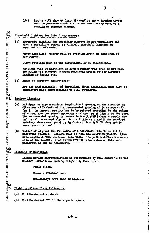
( iv) lights ni l l show at least $0 candles and a dimming device mst he provided which will allow for dinming dovai to 5 candles at Ttiftyjnmn dinning.
-4, Threahold Lighting fear Sujbaidlarpr Runways
(a) Threshold lighting for sufcsidary lunways is not oompulaory mit wdneii a subsidiary runway is lighted, threshold lighting is required at both ends»
Where Installedt colour will be aviation green at both ends of the runway.
Idght fittings itust be uni-direct ional or bi-directional.
Pittings will be installed in such a manner that they do not form obstacles for aircraft leaving readiness aprons or for aircraft landing or taking off .
(b) Angle of approach indicators : -
Are not indi spc ns able. I f installed, these indicators mist have the characteristics corresponding to ICAO standards.
061 -5. Taxiway Lighting
(a) Fittings to have a maxinuai longitudinal spacing on the straight of 65 metres (220 feet) with a recommended spacing of 50 metres (170 feet)* Cn curves, spacing has to be reduced according to the radius of curve, and the actual appearance of the row of lights on the spot. The rectwiended spacing on curves is D « 3.46^ (where r equals the radius of the curved edge which the lights mark and 0 the required spacing) when measurewent is in feet and D = 1. 1 then metric measurement is used*
(b) Colour of lights: the two sides of a taxitrack have to bc l i t by different colours. Colours will be blue end aviation yellow; (The bine lights define the inner edge while 'he yellow define the outer edge of the track). (See DHIEED STATES reservation an this sub-paragraph at end of Agreement).
061 -6. Lighting of Obstacles.
lights having characteristics as recommended by ICAO Annex 1if to the Chicago Convention, A r t 5» Chapter 3» K r . 3*3*5*
Fixed light.
Colour: aviation red.
Bidlliancyt more than 10 candles.
361
-7* IAghfciiyt of Ancillary Indicators.
(a) Ho illuminated windsock
(b) 1to illuminated flTn in the signals square.
DE
CLA
SSIF
IED
- PU
BLI
CLY
DIS
CLO
SED
- P
DN
(201
2)00
08 -
DÉ
CLA
SSIF
IÉ -
MIS
EN
LE
CT
UR
E P
UB
LIQ
UE

O Cl
(c) Ho other lights in the signala square.
(d) Marahalling points on the taxiway: where a marshalling point exists on the taxiway, i t is to he indicated by a double blue light on the inner edge of the taxiway approximately 75 metres (250 feet) from the uagts of the runway*
3061
-8. Crash landing Strips
Jtot to be l i t by permanent installation.
3061 -9. Lighting of Runway on Temporary Airfield
Vfhen a lighting system is installed on a temporary airfield, this system will be such that the terms of STAKAG 3061 can be progressively applied. The interval between lights will always be in multiples of 100 feet (30 metres).
RESERVATIONS
The following reservations have been made to the Agreement recorded on the preceding four pages.
HESEEVATIMt I
IhxaKrapih 2(a)
IENUIWK reserves the right to introduce red threshold lights for the far end of the runway.
HESERVAJICM I I
Paragraph 5(b)
In order "to provide conformity with ICAO standards and to allow for the present U.S. practice of using blue lights only on taxiways" the United States prefers the following revised wording of this sub-paragraph and reserves the right to adhere to the reserved text:-
"(b) Colour of Lights:
Tin two edges of a taxitrack may be l i t by blue lights an both edges or blue on one edge and yellow on the other. Colours will be aviation blue and aviation yellow. (These two colours are used and insofar is practicable, the blue lights SviRll define tbt **— to the runway while yellow lights define the farthest or outer edge)."
HESERTfATICM I I I
United KintfUxa
Reserves ïhe right not to provide threshold lighting at either end of subsidiary runways.
DE
CLA
SSIF
IED
- PU
BLI
CLY
DIS
CLO
SED
- P
DN
(201
2)00
08 -
DÉ
CLA
SSIF
IÉ -
MIS
EN
LE
CT
UR
E P
UB
LIQ
UE

b. Airfield Approach LightlnK.
TtM detailed criteria are contained in S T A K A S 3081, a complete copy of which follows on the next 5 pages:
IS
DE
CLA
SSIF
IED
- PU
BLI
CLY
DIS
CLO
SED
- P
DN
(201
2)00
08 -
DÉ
CLA
SSIF
IÉ -
MIS
EN
LE
CT
UR
E P
UB
LIQ
UE

O
STtHftS 3081
A I R P I E m AHBOftCH XJGHTIHg
TpRKB CF AÇranMRHT
Object
To standardise Airfield Approach Lighting an HATO Military Airfields.
Related Documenta
IEA(AIR) (51)6, dated 19th July, 1951 - Method of Woifc of the Air Board. S.A. 3039/52, dated 25th March, 1952 - IToriduig Party Eeport of the Air Board. MAS(AIR) (52) 107, dated Tth November, 1952 - Draft STAKAfi 3081.
Effective Date
24th April, 1953
Qfote 1 ; The effective date is the date upon iAich the Details cf Agreement became binding upon participating nations).
Hational Ratifying Beferences
Belgium JCS/790/10, dated 16th December, 1952. Canada * 5801-104-65 (A/ÖTAMD), dated 19th March, 1953. Denmark 6»kt.02.11.7-1, dated 14th Januaryl 1953. France * No. 356 Wa-$A/A/G/S/SG, dated 24th April, 1953. Greece UAS W/300/GZ> dated ,26th Jawary, 1953. Italy SMa No. 401257/S, dated 23rd February, 1953. Netherlands DCS 7458 bg/620. 3-2080, dated 19 January, 1953. Norvay LCK/H-1441, dated 3rd December, 1952. Portugal Beply not yet received. IVirfcey Keply not yet received. United Kingdom ÖKSD/40/53/A48/2, dated 16th January, 1953. United States
of America * MÀS/D3AP-476, dated 10th February, 1953.
( * - See pages 4 and !> Ibr .leservaticns) • (Note 2: Ratification means that official agreement has been given by the nations concerned to the conditions of the STAMAG). Supplenents
Supplements to the agreement may be proposed at any time by any of the partici-pants and will be processed in the same manner as the basic agreement.
Extension of Attreeaent to other Nations
This agreement may be extended to other Katicns becoming part of the Horth Atlantic Treaty Organisation.
Aareenient .
The provisions stated on the following four pages have been approved in accordance with the terms stated above by the countries listed, and no departure will be made from this agreement with ttoe exceptions of the reservations made on Pages 4. and 5 without prior consultation with, or in emergency, notification to, the Militazy Agency for Standardisation.
FOR THB MILITARY ACSHCX KH STANDABDISATICIt
G. H. MOOHS Captain (s)B.H., Senior Secretary
DE
CLA
SSIF
IED
- PU
BLI
CLY
DIS
CLO
SED
- P
DN
(201
2)00
08 -
DÉ
CLA
SSIF
IÉ -
MIS
EN
LE
CT
UR
E P
UB
LIQ
UE

SEECIgIGmqM FOR IAX-OOT OF AUtFIEm AFEBOACE LIGHTING
Approach to that direction of the main runway intended for instrument approaches
(a) High intensity approach lighting la to be -used.
( i ) A centre-line and five croaa-bar (CL5 B) approach lighting system is to be Installedt
( i i ) Sub-paragraphs (b) and (c) below set out the recommended lay-out and tolerances. Uodexate divergencies from these recomm-endations will not be critical so long as the essential pattern is maintained.
( i i i ) Vfhere site conditions render the installation of the fül l pattein impracticable a shortened form of the system should be provided.
(b) The centre-line
( i ) A centre-line on the extension of the axis cf the runway with an overall length of 900 metres (3,000 feet). The centre-line of the system to extend up to the runway threshold.
( i i ) Pittings to be spaced at a nominal distance of 100 feet (30 metie^ apart.
( i l l ) The first portion, extending 450 metres (1,500 feet) from the runway threshold, i s to consist of a single light fittings and the remaining 450 metres (1,500 feet) is to consist « f a double light fittings with each light spaced metres (5 feet) apart transversly. One single row of lights over the overall length will meet the minlwum requirement. Where double fittings are installed they should be turned away from the centre line at an angle of approximately 7¾ .
(iv) The fittingst tte fittings will consist of uni-directional incandescent white lights. The following intensity character-istics are recownended;-
± 7|-0 divergency in the horizontal plane - 20,000 candles
+ 12¾° divergence in the horizontal plane - 5,000 candles
Outside these divergencies there should be as l i tt le light as possible* Beam spread in the vertical plane may be less than that specified for the horizontal plane.
(v) Stages of brilliance required:
100% - 10$ - 1% - ,1% - .035( approximately.
(vi) Gradient. It i s desirable that as much of the syetem as is practicable is to be installed at runway level. The lay-out and gradient tolerances recommended are set out on the attached drawing* D
EC
LASS
IFIE
D -
PUB
LIC
LY D
ISC
LOSE
D -
PD
N(2
012)
0008
- D
ÉC
LASS
IFIÉ
- M
IS E
N L
EC
TU
RE
PU
BLI
QU
E

( c ) ( i ) TO» crossbars ans to be sited symetrically about the axis of the runway and are to subtend an angle of approximately 3° at the point of origin. The point of origin of the system is to be located 300 metres (1,000 feet) from the associated thresh-old measured along the runway centre-line. When the long-itudinal spacing between the bars is 150 metres (500 feet ) , the lights are to be spaced at 3 metres (9 feet) lateral intervals. The outside lights of the cross-bars will in a l l cases l i e on the T 3 "Ines iWhiCh includes an angle of 3° at the point of origin. The number of lights an the bars wil l be:
1 s t b a r - 2 x 4
2nd bar - 2 x 5
3rd bar - 2 x 6
^th bar - 2 x 7
5th bar - 2 x 8
( i i ) The characteristics of the fittings and the stages of brilliance required are to be identical to that of the centre line*
( i l l ) Cross-falls* The bars are to be kept on a horizontal plane where possible. Ko inclination tolerances are allowed on the 1st or 2nd bars from the threshold.
( iv) Tolerances in longitudinal spacing. I f 1 in order to overcome obstacles with gradient differences cross-bars must have a different longitudinal spacing from that recoranended, then the acceptable tolerances will be those which maintain a correct perspective of the approach system (height and dimensions have to be corrected accordingly).
(v) Direction of the beam of lights. The axis of the beams of a l l lights in the 3 outer cross-fears wi l l be turned outwards to an angle of approximately The axis of the beams of a l l the lights in the f i r s t 2 cross-bars wi l l be parallel to the centre line.
(e) Electrical Supply of Approach lighting
The sane method as that defined for the electrical supply to main instxument runways wi l l be adopted talcing into account the fact that the electric power may be supplied fron a single source*
( f ) Control
Benote control from the Toper is to be provided plus the possibility of oontrol direct from the transformer stations*
3081 -2. Subsidiary approach at the opposite end of the wain runway.
(a) Approach lighting is not compulsory. «
( i ) Where approach lighting is installed i t is to consist of a min-imal of 4 centre-line with a single light fittings giving an IntMisity suitable for use with the rummy lighting.
3081 -3* Approach lighting for subsidiary runways. (The subsidiary approach to the
main runway is covered under paragraph 2 above).
(a ) Iknr intensity lighting.
DE
CLA
SSIF
IED
- PU
BLI
CLY
DIS
CLO
SED
- P
DN
(201
2)00
08 -
DÉ
CLA
SSIF
IÉ -
MIS
EN
LE
CT
UR
E P
UB
LIQ
UE

( i ) Approach lighting to subsidiary runways is not compulsory.
( i i ) Vhere the subsidiary runway is l i t the direction of the lattüng shall bo indicated by a visual sign which will be one of the two following means: -
a. A centre-line which may be reduced to a ni mim of Z white lights on the approach, the lights being uni or omni-directional according to the runway lights, with a brilliancy of at least 50 candles.
b. A portable illuminated T to the port side when viewed from the approach and near the down wind end of the runway.
JOfrI -U* Llflhtlng Syatwn on the Approach of a Temporary Airfield.
The Installation of a lighting system on the approach of a temporary airfield Is not compulsory.
Where such a lighting system is considered necessary it shall be installed in accordance with the principles of the fixed system.
RBgERVATItBS
The following reservations have been made to the agreement recorded on the preceding three (3) pages*
RESERVATION I
IAKADA
Canada approves STANAG 3061 (for European Airfields) with the following oinor reservations
( i ) Beference para l(b)(v)* The BOA? reserves the right to -use brilliancy stages of 100 , 2gj(, 1JÉ and 0.2J1 Those stages give a wider selection and indications are that the minimum of 0.2$ is net too bright under clear conditions.
( i i ) Beference para 1(c)(1). As apposed to the specified number of lights on the oro33-bars, the RCAP reserves the right to use a spacing of 9, 13, 15, 17 and 21. This is an increase in the number of lights specified in the 3TANAG, and, in the opinion of tile RCAF, will give a more even spacing of the lights.
( i l l ) Beference para 1(0)(7). The BCAP is now investigating settings from approximately 5 - 7¾° and therefore reserves decision en this item at this time*
HESERVATIOtJ I I
The centre-line for the f irst 300 metres (1,000 feet) outward from the runway threshold will be replaced by two parallel rows cf red lights. These Lights will face the direction of landing and will be spaced every 30 metres |100 feet): 3 lights on the left , 1 light on the right*
DE
CLA
SSIF
IED
- PU
BLI
CLY
DIS
CLO
SED
- P
DN
(201
2)00
08 -
DÉ
CLA
SSIF
IÉ -
MIS
EN
LE
CT
UR
E P
UB
LIQ
UE

O
HBSKRVflffION I I I
PWHED SIfcEBS OP AMEtUEA
(a) The centreline for the f irst 1,000 feet outward from the runway threshold «ay be replaced by a parallel row system of lights. The lights used to form the parallel row should be at a fixed distance from the axi i of the runway and shall be unique by reason of configuration and colour so that they are unmistakable from any other lights or lighting used in the approach and runway lighting facilities.
(b) The outer 2,000 feet of the centreline and croaa-bar system may be deleted wholly or in part where such installation is impractical by reasons of terrain and/or procurement of real estate.
3O8I -5
DE
CLA
SSIF
IED
- PU
BLI
CLY
DIS
CLO
SED
- P
DN
(201
2)00
08 -
DÉ
CLA
SSIF
IÉ -
MIS
EN
LE
CT
UR
E P
UB
LIQ
UE

Item 9 - Standby Electric Power Supjplg
(Suggested Guidance in Appendix Bj Page 29)
3ÛO KVA will be provided at main and redeployment airfields for emer-gency (standby) electric power for communications facilities, runway lighting, FQL installations and other essential services. Ihis emergency power supply will be provided by a minimum of 3 generators.
Item 10 - Aircraft Fuel Uaderftround Storage
10b. Dlapereal
(1) At main and redeployment airfields fuel storage must be dis-persed over not less than three locations with minimum distance between storage locations of 500 metres.
( i i ) At alternative airfields storage must be dispersed over not less than two locations with a minimum distance between storage locations of $00 metres.
( i i i ) Individual tanks should not exceed 400,000 litres capacity.
(Iv) In order that damage to one tank will not jeopardize the safety of adjacent tanks in the same group, individual tanks in a group will be aeparated by a minimum distance of 2 metres between shells.
10b. Filling and Dispensing
( i ] Tanks within each dispersed group will be interconnected to facilitate fi l l ing and dispensing,
( i l ) A separate dispensing facility for each grade or type of fuel storage at each location, complete with pumping and other ancillary equipment, will be provided at each group of tanks.
( i i i ) Dispensing facilities for aircraft fuels will have a minimum capacity of 1900 litres per minute at each dispensing unit.
IOc. Pefuelling. Defuelling facilities, complete with pumps and necessary piping, are required in each of three squadron areas. This requirement is not to be construed as Increasing the capacity of NATO-caamon infrastructure underground fuel storage specified in table KO. 1.
lOd, Protection of Fuel Ayainst Contamination. Pipe fittings, pvuçts and other ancillary equipment shall be of a type and material that will not deteriorate by chemical reaction with the components of the fuel they accommodate, All necessary precautions will be taken to avoid contami-nation when more than one grade or type of fuel is handled.
lOe. Safety. Design and construction shall take account of a l l handling risks pertinent to the properties of liquid fuel.
DE
CLA
SSIF
IED
- PU
BLI
CLY
DIS
CLO
SED
- P
DN
(201
2)00
08 -
DÉ
CLA
SSIF
IÉ -
MIS
EN
LE
CT
UR
E P
UB
LIQ
UE

O > Appandix A Xtens 11 -14
ItaM 11
Mil.
Item 12 - Motor Fuel Storage
Dispensing and refilling facilities including pumps and other ancillary equipment will be provided. A minimum of two dispensing hydrants will be provided for dispensing motor fuel and these shall have a minimum capacity of 50 litres per minute each.
Item 13
Nil,
Item 14 - Ammunition Storage
14a. Covered and Blastproof. There are several acceptable methods of designing structures to fu l f i l l this requirement. Functions of the structure a r e ;
( i ) To protect stored ammunition frön strafing and flying objects by means of cover, preferably of earth ever an arched otr damad reinforced concrete structure.
( i i ) To protect against the effects of blast from nearby ex-ploding bembs through heavily mounded earth on the sides.
( i i i ) To protect other critical areas, such as other stored ammu-nition, operational structures and parked aircraft, by designing the struc-ture so that the directional effect of any structural weakness will be away front Uiese other areas.
(iv) To protect the structure from lightning) as required in the locality, through lightning rods which, together with other metal parts, such as reinforcing steel, are tied into a permanent ground with a heavy copper wire,
(v) To minimize risk of sparking by following standard national practice for this purpose in construction of floors. NoroaIly, electrical fixtures will not be provided, but if desired, only explosion-proof fittings will be used*
li,b. Open and Reveted Hardstands. The requirements for protection against blast and of other critical areas are the same for these hardstands as specified in 14a ( i i ) and ( i i i ) above for covered and blastproof storage,
14c, Safety Clearances. Until a STANAG is published outlining ammu-nition storage safety clearances, the present explosives storage laws and regulations of the host or user nation are acceptable, it being understood that the «ore stringent requirements should apply. If additional guidance is desired, HAF or USAF criteria (which are similar) may be used.
DE
CLA
SSIF
IED
- PU
BLI
CLY
DIS
CLO
SED
- P
DN
(201
2)00
08 -
DÉ
CLA
SSIF
IÉ -
MIS
EN
LE
CT
UR
E P
UB
LIQ
UE

Item 15 - Control Tower and Meteorological Building
15à. location. Tbe control tower shall be located to obtain wxluum visibility of the runway, parallel taxiway and airfield approaches and good visibility of taxitracks and dispersals. Standard clearances will be main-tained in relation to the runway and parallel taxiway.
15b. Size. The minimum size of the control room shall be 6 metres between parallel walls.
Item 16
Kil.
Item 17 - Squadron Oberatlons Booms
(Suggested Guidance in Appendix B1 page 30)
Nil.
Item ia
MU.
Item I^ - Manpars
(Suggested Guidance in Appendix B, page 30 )
The minimum clear door opening for each hangar is 30 metres wide by 6.1 Metres high. "Where an airfield is designated as the station for a unit equipped with aircraft larger than fighter aircraft and appreciably larger hanger door openings are considered an operational requirement, the matter will be referred to SNAPS for decision,
Item 20 - Storage or Iiarehouae Buildings
(Suggested Cuidance in Appendix B, page 30)
Nil.
DE
CLA
SSIF
IED
- PU
BLI
CLY
DIS
CLO
SED
- P
DN
(201
2)00
08 -
DÉ
CLA
SSIF
IÉ -
MIS
EN
LE
CT
UR
E P
UB
LIQ
UE

c - - -
Item 21 - Maintenance Shopa
(Suggested Guidance in Appendix Bf page JO)
Nil.
Item 22 - Technical Shops
(Suggested Guidance in Appendix B1 page 30)
Nil.
Item 23 - Motor Vehicle Maintenance Shop
(Suggested Quidance in Appendix B1 page 31)
Nil.
Item 2Jt - Crash and Fire Station
(Suggested Guidance in Appendix B1 page 31)
Nil.
Item 25
Nil.
Item 26 - Pisperssl Huts
One of these huts will be located in each of three dispersal areas to provide shelter close to dispersed aircraft for crews in readiness. I f squadron operations buildings or squadron hangars with leantos are located in dispersal areas, the space specified for dispersal huts can be added to either of these buildings.
Item 27 - Ccwmunicstlnna Building snd Ttemote Tranaiaitter Bnilrtin^
Detailed criteria, including siting requirements, are being disseminated in a separate SHAPE document.
DE
CLA
SSIF
IED
- PU
BLI
CLY
DIS
CLO
SED
- P
DN
(201
2)00
08 -
DÉ
CLA
SSIF
IÉ -
MIS
EN
LE
CT
UR
E P
UB
LIQ
UE

Item 28 - Communications
Detailed criteria are being disseminated in a separate SHAPS document.
/Br message DGP 940051 (TOSHAP 417) of 28 Ilay 1953 Standing Group approved for main and redeployment airfields the standards listed in Table * No, 1 for Item 28b, Ualn Outlet Cable and Item 28c. Uain Telephone Switchboard, instead of the previously recommended standards of
"28b. Uain Outlet Cables 2 each 56-pair or 2 each TMA e quad, in accordance with local engineering prac-tice, to provide alternate routing.
"28c. Uain Telephone Switchboard 200 line, extensible to 360 line. Of the order of 40 subscribers per operating posit icu^
Regarding the SHAPE recommendation that, in cases where installation of the equipment provided in the earlier recommendations for these two items was already underway or completed, the whole of the larger instal-lation should be authorized as NATO-common infrastructure, Standing Oroup stated in DEF 939810 (STAHLO 278) of 26 Uay 1953 that the SHAPE rec«amen-dât ions should be considered In light of the financial Implications and recomended that the SHAPE proposals be referred to the Infrastructure Payments and Progress Comnittee, NAC, for detailed examination. The matter is st i l l under consideration by the Cootnittee^
Item 29 - GCA Hardstand
Detailed criteria are being disseminated in a separate SHAPE document.
Item 30 - Utilities
(Suggested Guidance in Appendix B, page 31]
The host nation will provide»
30a. Ifater Supply. Potable water at the airfield boundary or on-site pump outlet in sufficient quantity for 3,000 men at 150 litres per man per day at main and redeployment airfields, and for the maintenance party of 50 men at alternative airfields. Hater shall be under sufficient pressure at the airfield boundary or at the on-site well head pump outlet for domestic and fire fighting use.
30b, Klectric Power. A minimum of 860 KVA electric power at main and redeployment airfields and 250 KVA electric power at alternative air-fields to the main incoming aub-station(a) at the supply voltage. The main incoming aub-station(s) Including transformers and switching gear to the airfield distribution voltage are a host nation responsibility.
DE
CLA
SSIF
IED
- PU
BLI
CLY
DIS
CLO
SED
- P
DN
(201
2)00
08 -
DÉ
CLA
SSIF
IÉ -
MIS
EN
LE
CT
UR
E P
UB
LIQ
UE

f ^ r f
30c, Sewerage, Treatment facilities for sanitary sewage and any dis-posal required beyond the boundary fence for sanitary sewage and storm water. Treatment design will be based on 3000 men at 150 litres per man per day for »ain and redeployment airfields and 50 men at 150 litres per man per day at alternative airfields. When individual septic tanks at isolated buildings are more economical than long connecting mains to the central sanitary sewage system, these tanks shall be provided as part of NATO-common infra-structure.
Item 31 - Access Head
31a. Load Bearing Capacity
English units: single axle
Uetric units : single axle
31b. VJidth; 5.5 metres minimum.
load - 11,000 pounds minimum,
load - 5 metric tons minimum.
Item 32
Nil.
Item 33 - Signal Coiaiminications to Lon^-Lines Network
Biis item is now included under Item 28. Detailed criteria are being disseminated in a separate SHAFE document.
Item 34 - Fencing. Gates and Observation Towers
(Suggested Guidance in Appendix Bj page 32)
34a, Ferlneter Fcncing. Seauired to keep farm animals from entering operational and flying areas and to deter trespassing by unauthorized personnel,
34b. Security Fencing. Hequired for ammunition and FOL storage areas of main and redeploy&ent airfields. ^HAPE has recommended to Standing Srcup that this fencing be required for alternative airfields a l so^
Item 35 - Alert Warning System
This item has been deleted by Standing Group as a minimum operational requirement. If required, it is to be provided by the user nation.
DE
CLA
SSIF
IED
- PU
BLI
CLY
DIS
CLO
SED
- P
DN
(201
2)00
08 -
DÉ
CLA
SSIF
IÉ -
MIS
EN
LE
CT
UR
E P
UB
LIQ
UE

Item 36 - Démolition Systems
{Suggested Quidance in Appendix B1 pages 32 and 33)
36« • Item I-Bumrar and Item 2-Parallel Taxiway. ^HAFB has recommended to Standing Group approval of the following wording in accordance with the SHAPE view of minimum requirements; 1Weans of demolition at 100 metre inter-vals throughout the entire length required.^
36b. Item IO-Aircrsft Fuel Underground Storage and Item 12-Hotor FUel Underground Storage. Means of destroying fuel and pumping and dispensing equipment and rendering tankage useless required.
36c. Item 14-Ammunition Storage. Iteans of destroying buildings and ammunition required.
36c. Item lS-Conmunications Building and Bemote Transmitter Building. Ileans of destroying communications equipment required.
Item 37 - Personnel Housing
(Suggested Guidance in Appendix B1 pages 33 and 34)
37a. Minimum _Accommodation for Maintenance Parties for Redeployment and Alternative Airfields.
Bedeployment
Item For 100 men
Mess Hall 74 square metres
Kitchen, food preparation and storage 56 square metres Company offices and storage
Technical Stares
Company storage, total for two rooms
Recreation room
Officers Living Accomodation
Mess
Sleeping
Bath with shower i.e. Urinal
Hash basins
37 square metres
» i l
37 square metres 56 square HBtres
Alternative For 50 men
37 square metres
47 square metres
29 square metres
56 square metres
26 square metres
37 square metres
28 square metres 19 square metres
13 square metres 13 square metres net for each o f f i - net for each off i -cer; for total of 4 officers.
1
1
1
4
cerj for total of 2 officers.
1
1
1
2
DE
CLA
SSIF
IED
- PU
BLI
CLY
DIS
CLO
SED
- P
DN
(201
2)00
08 -
DÉ
CLA
SSIF
IÉ -
MIS
EN
LE
CT
UR
E P
UB
LIQ
UE

NCO1 a Living Accoroaodatiwi
IIeas and recreation as annex to •en's mess 37 square metres 19 square metres
Sleeping 9 Square metres net for each NGO; for total of 10 MOQs.
9 square metres net for each NOOj for total of 5 MCOs.
Hash basins 2 1
Bath with shower 1 1
«.C. 1 1
Urinal 1 1
Hen's Idving Accomodation 6 square metres per man
6 square metres per man
Showers 5 3
Bath 2 1
Hash basins 10 5
U.C. seats 6 3
Urinals U 2
37b, MiniTHim Scales of Accomodation for Camo Structures on Redeploar-ment Airfields. Sxcept for the maintenance party of IOO men, peacetime housing will not be provided. In war the wing will be accommodated in tentage. The following scale of camp structures will be built In peacetime in the camp areaat
( i ) Kitehensi 0.5 square metre per mi in.
( i i ) Ablutlont 6 metres of trough type wash facilities for each 100 men.
( i i i ) Showerst 5¾
( iv) Drying room: 1 square mstrs for each 10 men; to be heated by boiler in shower room.
(v) Orlnalst 3 metre« of urinal trough per 100 men.
(vi) Latrine seats t 5# of complement.
(vii ) Incineratorst 1 per squadron camp area; 2 in the headquarters area.
DE
CLA
SSIF
IED
- PU
BLI
CLY
DIS
CLO
SED
- P
DN
(201
2)00
08 -
DÉ
CLA
SSIF
IÉ -
MIS
EN
LE
CT
UR
E P
UB
LIQ
UE

) t
Appendix B Introduction and Item X
APPENDIX B
This appendix presents SHAPB suggested guidance on certain features of planning and construction of tactical air force airfields. Khile not manda-tory criteria and standards, these recommendations constitute what SHAPE considers to be desirable solutions to some of the problems encountered in airfield construction« Mations are urged to make maximum use of these suggestions«
Item 1 - Rmway
la. Lead Bearing Capacity. Technical guidance on the design of airfield pavements will be disseminated by the airfield experts of the NAC international staff. This guidance will cover safety factors and will take account of the need to use greater safety factors in the design of other airfield pavements than for the center part of the runway and parts of the parallel taxiway between taxitrack intersections.
lb. Psvement. Prior to using water mix cement other than Portland Cement, as may be standard practice in certain districts, the airfield experts of the NAC International staff should be consulted. Their in-structions should be complied with in the use of such other water mix ce-ments.
lc. Drainage. The requirement for a transverse grade of 1.5¾ ia based on the minimum grade for effective drainage. In the ordinary case, this grade should be applied transversely in opposite directions from the centre line of the runway to give a crown so that drainage is to both edges of the runway. However, en sites with natural drainage transverse to the runway centre-line, a crowned runway may involve excessive earth work or a costly drainage system, and in these cases the same transverse grade across the full runway width may prove more economical. Based on the same consider-ations it may prove desirable to have an up-hill shoulder drained toward the runway. This solution is acceptable provided adequate drains are installed at the edge of the pavement to prevent water frcm the shoulder draining across the pavement and carrying with it dirt and other danger-ous debris. Drains constructed on the edge of aircraft pavements should be capable of supporting aircraft, should be designed to prevent entrance of water beneath the pavement and should not obstruct passage from the runway to shoulders in the event of sccidental overruns.
Id. Shoulders. Overruns and Bnd Cleared Zones. In addition to providing a surface with adequate bearing capacity, theae areas must be free of dust. To prevent dust, these surfaces might be treated so as to support a dense growth of grass. Ihere necessary, a minimum thickness of 10 centimetres of top soil planted with a hardy variety of grass is recommended. When grass growing is impracticable, soil stabilization may be necessary to a chieve a dust-free surface. Either bituminous material or Portland Cement may be required for stabilization depending on local soil conditions.
le . Concealment. Camouflage has not been included as a standard airfield requirement, but effective measures to conceal sirfield pave-ments are of great importance, Acperiments are in progress on the toning down of airfield pavements, and StttPE will take an active interest in the dissemination and exchange of the latest information on toning down re-sulting from investigations by NATO nations and SHAPE subordinate commands.
DE
CLA
SSIF
IED
- PU
BLI
CLY
DIS
CLO
SED
- P
DN
(201
2)00
08 -
DÉ
CLA
SSIF
IÉ -
MIS
EN
LE
CT
UR
E P
UB
LIQ
UE

IT. Grades. When large amounts of earthwork are involved in meeting the prescribed longitudinal grades and appreciable savings can be achieved by slight variations from these grades, consideration will be given to approval of deviations from standards which are adequately Justified on economic grounds and are operationally acceptable to the allied air commander concerned.
Item 2 - Parallel Tyiwaft
2a. Load Bearing Capacity. See Item 1 - Hunway1 page 27.
2b. Other suggestions for runway construction apply equally to the parallel taxiway,
. A«
item 3 - Taxitracks
See Item 1 - Rnnway1 subparagraph la* page 27,
Item 4 - Dispersal Hqrdstanda
4a. Load Bearing Capacity. See Item 1 - Runway, page 27.
4b. Layout. The planning of dispersal areas should be based en the following considerations:
( i ) Convenience of take-off: The squadron dispersals should be located close to the ends of the runway, but outside the clearance zones, and should be so sited so as to permit a short, uninterrupted run to the alert platforms. This should be achieved by oblique connections from hardstands to the main feeder taxitrack, absence of sharp bends in taxi-tracks and preferably two routes to the runway.
( i i ) Number of hardstands per dispersal area: each dispersal area should preferably include 12 double hardstands. Local conditions nay, however, dictate building of three groups of 16 hardstands.
( i l l ) Safety: protection of hardstands by revetnsnts should be adopted wherever possible and particularly where surplus excavated material is produced during the construction of the hardstands,
(iv) Cencealmant: dispersals should not be arranged in stan-dardized or symmetrical geometrical patterns which will present a stereo-typed target to enemy aircraft, Hardstands should be located irregularly to blend as much as possible Into the terrain and take advantage of natural concealment.
4c. Bsvetments. Jet blast and noise have introduced new problems in the design and construction of revetments. The search for economical de-signs which are satisfactory frcm al l standpoints and do not require ex-cessive maintenance has proved very difficult, furthermore, standardization of revetment design is neither practicable nor desirable since varying con-ditions may make the most desirable solutions significantly different from one airfield to another. SHAPE will take an active interest in the dissém-ination and exchange of infonaation on satisfactory revetment design
DE
CLA
SSIF
IED
- PU
BLI
CLY
DIS
CLO
SED
- P
DN
(201
2)00
08 -
DÉ
CLA
SSIF
IÉ -
MIS
EN
LE
CT
UR
E P
UB
LIQ
UE

' O
Appendix B Items 4 - 16
resulting from investigations by NATO nations and SHAPE subordinate commands.
5a. Load Bearing Capacity. See Item 1 - Runway, page 27-
5b. Layout. Although the f irst alternative alert platform shown in Annex 5 has been constructed on some airfields where IDP aircraft are stationed, the second and third alternative alert platforms shown in Annex 5 are considered more desirable for SHAPE airfields since these alter-natives are suitable not only for IDF missions but also for other aircraft and give appreciably greater clearance from the runway.
Iteny 6 - Aprone for Inspection and Maintenance of Aircraft
See Item 1 - fiunway, subparagraph la , page 27.
The load bearing capacity and widths prescribed in Appendix A are mini-mum. They do not preclude construction of stronger and wider roads, «Aich should be built whenever required to provide for anticipated traff ic. In general, road construction will be best carried out in accordance with local practice, modified as necessary to satisfy the needs of the user nation.
Standby electric power supply should be provided through generators dispersed at locations nesr their emergency loads.
Item 5 - Alert Platforms
Item 7 - Internal - oads
Item 8
Mil.
Item 9 - Standby Electric Power Supply •
Items Iq - 16
Nil. DE
CLA
SSIF
IED
- PU
BLI
CLY
DIS
CLO
SED
- P
DN
(201
2)00
08 -
DÉ
CLA
SSIF
IÉ -
MIS
EN
LE
CT
UR
E P
UB
LIQ
UE

Item 17 - Squadron Operations Rooaa
These buildings will normally be located one in each cf three squadron dispersal areas.
Iteti ie
Mil.
Item 19 - Hangars
Item 19 allows 5,600 square metres for hangars at main airfields only. Items 21 and 22 allow a total of 3,435 square metres for maintenance and technical shops. At main airfields it is desirable to have one maintenance hangar and three squadron hangars. To ensure workable hangar space the allowable hangar area may be supplemented by a portion of the allowable maintenance shop area. Uaintenance and technical shops at main airfields may be built as single or multiple story leantos to the hangars.
Item 20 - Storage or "Warehouse Buildings
Whether or not fixed shelving and storage bins are installed and the scale on which they are provided in storage or warehouse buildings should be based on established local practice for similar civil and military instal-lations in the host country. '
Item 21 - Ualntenance Shops
and
Item 22 - Technical Shops
21a. The aircraft maintenance and technical shops may be constructed as single or multiple story leantos to the maintenance and/or other hangars. A portion of the allowable space may be added to the allowable hangar space to ensure workable hangar space.
21b. Whether or not fixed shelving, storage bins, racks or benches are installed and the scale on which they are provided in maintenance shop» and technical shops should be based on established local practice for similar civil and military installations in the host country. D
EC
LASS
IFIE
D -
PUB
LIC
LY D
ISC
LOSE
D -
PD
N(2
012)
0008
- D
ÉC
LASS
IFIÉ
- M
IS E
N L
EC
TU
RE
PU
BLI
QU
E

Q D
Item 23 - Motor Vehicle Maintenance Shop
Whether or not fixed shelving, storage bins, racks or benches are in-stalled and the scale on which the/ are provided in the motor vehicle main-tenance shop should be based on established local practice for similar civil installations in the host country.
It is important that this facility be located in an area where easy access to the runway is available at all times for Imediate crash fire fighting. Good access to the remainder of the station should be avail-able for normal f i re fighting requirements.
30a. SHAPE has reconoended that technical guidance on the design of the on-base electrical distribution system be disseminsted by the airfield experts of the NAC International Staff^7
30b. Depending upon the individual airfield layout, it may be desir-able to construct the internal electric power distribution system in the form of a "ring main" in order to ensure the availability of power in the event of damage end during servicing and repair of the line.
30c. Central Heating. Vhere required by climactic conditions, cen-tral heating is an inherent part of the requirements for standard buildings and may be provided either from a central boiler house or by separate units in individual buildings, depending on local practice and economy. The same syste» may be used to heat both standard buildings and user nation require-ments, it being understood that only so much of this system as is required for standard buildings is part of KATO-ccenon infrastructure.
Item 2U - Crash and Fire Station
Itews 2^ - 29
Sil
Item ?0 - Utilities
Items 31 -
NU.
DE
CLA
SSIF
IED
- PU
BLI
CLY
DIS
CLO
SED
- P
DN
(201
2)00
08 -
DÉ
CLA
SSIF
IÉ -
MIS
EN
LE
CT
UR
E P
UB
LIQ
UE

Itea 34 - FencingjGates and Observation Towers
34a. Perinteter Fencing. The perimeter fencing requirement to exclude farm animals from operations and flying areas and to deter unauthorized trespassers may be met by the construction of a 5-strand barbed-wire or 1.5 metre animal-wire fence, with 3-strand barbed-wire overhang, on posts spaced approximately 4 metres apart.
34b. Security Fencing. The security fencing requirement for ammu-nition and POL storage areas nay be met by s 2-metre-high chain link fence with 3-strand barbed-wire overhang. Whether or not security fencing is required for communications sites will depend on security conditions in the general area and the location of the sites with respect to other airfield installations.
34c. Gates. A bascule-type barrier gate may be included at the main airfield entrance. All other gates should be swing type.
Item 35
Nil.'
Item 36 - Demolition Systems
36a. The method used for the demolition of airfield runways must give ful l consideration to the following factors.
( i ) Air traffic must not be Interrupted during either the pre-paration of the demolition system or the final placing of the explosive charge.
( i i ) The preparatory work must be sufficiently solid not to be damaged by, or cause daaage to aircraft.
( i i i ) The preparatory work must be waterproof or self-draining, protected against debris, and must not Interfere with airfield drainage.'
( iv ) Quick charging with explosives must be possible in an emergency.
36b. It is recommended that charges be calculated so as to produce the greatest possible difficulty to repair efforts. In the case of concrete pavements, the effect can best be accomplished by breaking the surface into very large slabs and heaving these slabs to a height of about i metre so that considerable clearance work is required before repair work can be started. For this purpose, relatively "slow" explosive is desirable. The complete disintegration of the concrete slab is not essential nor even desirable, inasmuch as a trench blown by a heavy charge Is relatively easy to sweep and repair.
36c. Of the methods devised to accomplish this, the most promising is the placing of water proof steel or cast iron pipe under the runway at ap-proximately loo metre intervals. At the proper time, the pipe can be loaded with explosive and subsequently fired. The exact diameter of the pipe appears unimportant, provided it is large enough to accept the explosive and the
DE
CLA
SSIF
IED
- PU
BLI
CLY
DIS
CLO
SED
- P
DN
(201
2)00
08 -
DÉ
CLA
SSIF
IÉ -
MIS
EN
LE
CT
UR
E P
UB
LIQ
UE

" v 1
Appendix B
J Iteas 36 - 37
loading means without force. The Joints of the pipe must be flush inside. The depth of the pipe below the surface depends on the thickness of compacted base and on the height of the water table, the optimum solution being to place the pipe between the bottom of the heavy compacted layer and the top of the water table. If the water table is high, it may be necessary to place the pipe within the compacted base.
36d, Where the preparations for demolition can be made during the course of the pavement construction, the following scheme has been suggested: steel or cast iron pipes, with water ti&ftt joints, are placed under runway for the ful l width of the runway pavement. The two ends of the pipe are curved up to the airfield surface. To permit the rapid insertion of the cnsrge, a wire cable is threaded through the pipe to be used as a pilot wire in pulling through the explosive charge, The two ends of the pipe are provided with water tißbt Caps to which the ends of the pilot wire are secured by de-tachable fasteners. Unless two open ends of the pipe are provided, the placing of the explosive charge by thrpsdint' it in from one end may prove impracticable, owing to slight variations in the level of the pipe joints caused by settlement. The use of manholes at each end of the pipe has also been suggested.
36e. Where the preparations for demolition must be made after the pavement construction has been completed, the following scheme was proven satisfactory in experinipnts conducted by the Engineers, Korthern Army Qroups a 4-inch (10-centimetre) diameter steel pipe, with screw joints was pushed under the pavement by means of a "Ireenlee*1 Hydrsulic Pipe Pusher. The pipe was pushed at a depth of approximately 4 feet snd extended for 60 feet across the runway, Thp "J^eenlee,, Hydraulic Fipe rusher, developed for the British Forces in World War I I , proved satisfactory in soft soils, but normally re-quires the addition of a wator Jea, in compacted soil. Khen the pipe is driven with an open end, it must be withdrawn afterward and waterproofing added to the end and Joints. Ths explosive was IiLrsducod into the pipe by lashing it , together with s lawth of detonating cord, to flexible rods or to jointed pipes which were fed in from manholes located just off the runway. The size of the manhole defends on the riethad of loading adopted.
36f. Eitperiiaents carried out ta nate fcy the QnftIneers, t«orthern Anny Gr^up,' show that, for a 12-inch (30.5 centimetre) concrete slab and a pipe at u depth of 4 feet (1.2 metres) below the surface, best results are ob-tained with a charge of | pound of trinitrotoluene (TIET) explosive per foot (.75 kilogram per metre). This cfiar^e broke tne pavement into large pieces along a line of about 3 feet (1 aetre) wide, heaved snd cracked the con-crete for about 10 feet (3 metres) on either side. Similar results ware obtained on an 8-inch (20-centioetre) concrete slab with a pipe tt e depth
ï'iji " feet (? tr-tros) c.nJ p carr af 3/4 ; sund ;-ar foot ( 1 , 1 * ! kil-. 'r -pe r sietre).
Item 37 - Personnel Housing
37a. Concealment. Although camouflage has not been included as s stan-dard airfield requirement, concealment must receive priority consideration in airfield planning. In general, careful use af existing terrain is far more economical and effective than artificial measures. The object should be to make the airfield as inconspicuous as possible from the air and to dis-perse facilities so as to minimize damage from bombs. Dispersal of buildings ' and other structures should not be conspicuously different from the pattern of adjacent communities or built-up areas. To the extent consistent with this objective, buildings should be dispersed on an irregular pattern, with 60 metres between buildings whenever possible. Double-story construction should be avoided, except when it is typical of the local area and airfield buildings will blend with surrounding built-up areas. Single-story construc-
DE
CLA
SSIF
IED
- PU
BLI
CLY
DIS
CLO
SED
- P
DN
(201
2)00
08 -
DÉ
CLA
SSIF
IÉ -
MIS
EN
LE
CT
UR
E P
UB
LIQ
UE

A p p m d l x B I t « * 37
tlon should te uMd Mptrlrily f6r vital Mldl i ig i t which user nations may wUh to protect »Ith blast walla. TsXli and reefs of buildings should not have a smooth reflect lng surf a oe and should be toned down in colour to blend with the landacape.
37b. T j b o of Construction. Construction will be normally of a twpo-rary nature with a l i f e of ten year a, with the exception of those buildings which, for reasons of security or the nature of the equipment houaed therein, Aay require a no re permanent type of construction.
DE
CLA
SSIF
IED
- PU
BLI
CLY
DIS
CLO
SED
- P
DN
(201
2)00
08 -
DÉ
CLA
SSIF
IÉ -
MIS
EN
LE
CT
UR
E P
UB
LIQ
UE
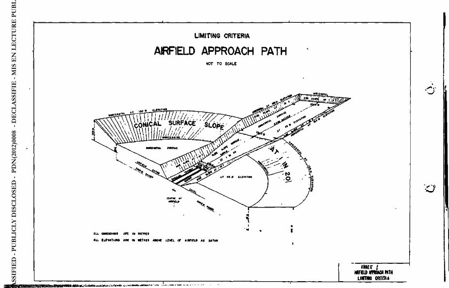
LIMITING CRITERIA
AIRFIELD APPROACH NOT TO SCALE
PATH
±
1 1 t U ä » * ^ VJ .L-ELV*-; r. « •
»««£1' t MIFXlD « m u H MTN
LIMTIM CfflTESi«
DE
CLA
SSIF
IED
- PU
BLI
CLY
DIS
CLO
SED
- P
DN
(201
2)00
08 -
DÉ
CLA
SSIF
IÉ -
MIS
EN
LE
CT
UR
E P
UB
LIQ
UE

DE
CLA
SSIF
IED
- PU
BLI
CLY
DIS
CLO
SED
- P
DN
(201
2)00
08 -
DÉ
CLA
SSIF
IÉ -
MIS
EN
LE
CT
UR
E P
UB
LIQ
UE

S E C T I O N A L E L E V ä T I O H O f A P P R O A C H F U * N & L L I M I T I N G C R I T C I I I A
NOT t o S C A L E .
t tw «r tmuL «MM« » t * «fnuu< i
fVtt^ttf * IM . I tl Lllk |t* tlHCv'n V 7' C.'UT'Hh *•<)•• ' HT
WtfILH et m» ««rum at A N H E J *
KtT I 0MJU. ( L t t M W ^ m M t I I uwTMb arrau
DE
CLA
SSIF
IED
- PU
BLI
CLY
DIS
CLO
SED
- P
DN
(201
2)00
08 -
DÉ
CLA
SSIF
IÉ -
MIS
EN
LE
CT
UR
E P
UB
LIQ
UE

Hfc.. y
- Q § D
EC
LASS
IFIE
D -
PUB
LIC
LY D
ISC
LOSE
D -
PD
N(2
012)
0008
- D
ÉC
LASS
IFIÉ
- M
IS E
N L
EC
TU
RE
PU
BLI
QU
E

DE
CLA
SSIF
IED
- PU
BLI
CLY
DIS
CLO
SED
- P
DN
(201
2)00
08 -
DÉ
CLA
SSIF
IÉ -
MIS
EN
LE
CT
UR
E P
UB
LIQ
UE