crime scene considerations: electronic control device ... · journal of the association for crime...
TRANSCRIPT

Journal of the Association for Crime Scene Reconstruction www.acsr.org37
Article Original Article
Crime Scene Considerations: Electronic Control Device (TASER®) Deployment
Article
R.T. Wyant, M.S.ab, Tom Burns ac & Kathy Geil b
a CRT Less Lethal, Inc., b Washington State Patrol Crime Lab, c Seattle Police Department
Copyright: © 2011 R.T. Wyant, Tom Burns & Kathy Geil. Copyright for this article is retained by the authors, with publication rights granted to the Association for Crime Scene Reconstruction. This is an Open Access article distributed under the terms of the Creative Commons Attribution-Noncommercial-No Derivatives License (http://creativecommons.org/licenses/by-nc-nd/3.0/) which permits unrestricted noncommercial use, distribution, and reproduction, provided the original work is properly cited and not changed in any way.
IntroductionSeattle 2000: As news cameras rolled,
an emotionally disturbed man was shot by police as he skipped down a crowded ur-ban sidewalk with a large knife in his hand and firearm in his waistband. Although deadly force was justified in that case, pub-lic outcry resulted for the police to have more non-lethal weapons at their disposal to confront resistant or combative subjects. The Seattle Police Department selected and implemented a TASER® program later that year [2].
Seattle 2001: A suicidal man with a knife charged an officer after the TASER M26 device failed to incapacitate him. The of-ficer’s shirt was sliced and the suspect was fatally wounded. As a result of the efforts to reconstruct the incident to determine why the device did not work, Electronic Control
Device (ECD) forensics was born. It was identified during the investigation of the in-cident that investigators were not educated on TASER deployments and much of the TASER evidence was not collected or pre-served [2].
During the last decade, variants of the above have played out in police jurisdic-tions throughout the United States and abroad. Most often, a controversial deploy-ment plays out in two forms, the ECD fails to incapacitate and the force is escalated or the suspect dies proximal to the use of the device [2]. These cases are often contro-versial and receive a lot of media attention. One of the most common questions is how much, if any, electrical energy the subject received during the ECD deployment. Un-fortunately, forensic considerations of ECD deployments are often overlooked in train-
Received: 03.09.2011Revised: 07.21.2011Accepted: 07.23.2011
Citation: Wyant, RT, Burns, T, & Geil, K. (2011). Crime Scene Considerations: Electronic Control Device (TASER) Deployment. Journal of the Association for Crime Scene Reconstruction, 17(3), 37-47.
Abstract: The demand for law enforcement to have access to less lethal tools has never been higher. Within the last ten years, products from TASER® International have dominated the marketplace and are now in use in more than 16,000 police agencies worldwide. As investigators, scientists, and crime scene analysts, Electronic Control Devices (ECD) such as TASERs will be encountered in casework. Their role, capabilities, and limitations must be understood to properly collect and analyze the evidence involved. These devices and their components can be analyzed to determine proper function, establish a hit or a miss, and in some cases determine the duration of shock to assist in the reconstruction of a field “failure” or in custody death.Keywords: TASER, electronic control device, electroshock weapon, conductive energy device, less-lethal, probe-knot junction, stun gun, excited delirium
Original Article

www.acsr.org Volume 17, Issue 3, Summer 201138
ing programs and post event investigations, even though a thorough analysis of the event can answer key questions [4].
It is paramount for the crime scene inves-tigator to understand the dynamics and use of ECDs as well as to identify and collect potential key evidence at the scene related to these devices. The investigation can de-termine if the ECD units were functioning properly, interpret and validate ECD firing data, and examine the wires and probes (grossly and microscopically) to determine other data such as duration of application, what the probes struck, or when and how they became dislodged. The authors rec-ommend that all crime scene investigators take, at minimum, a user-level TASER course to understand the components and how they are deployed in the field.
How do ECDs work?The TASER is an ECD designed to in-
capacitate a subject by overriding normal voluntary muscle activity. ECD’s are not to be confused with the traditional “stun-gun” that does not fire projectiles and relies on pain compliance only. As of December 2010, there were 527,000 TASER devices sold worldwide, easily making it the most popular ECD on the market and the brand
most likely encountered in casework [1]. There are some other competitors in the marketplace that the investigator should be familiar with such as Stinger, Karbon, and LEA Stun Pistol.
The TASER device consists of a main unit and detachable cartridge. The device is deployed by firing a proprietary TASER cartridge, which launches two wire-teth-ered probes (fig. 1). The cartridge is fired when electrical energy from the main unit ignites a small primer which forces a nitro-gen capsule rearward into a hollow punc-ture pin. Compressed nitrogen is released into two chambers forcing the probes, blast doors, Anti-Felon Identification tags (AFIDs), and other items forward out of the cartridge. The two metal probes (com-position dependent on generation type) are attached to thin insulated wires. The barbed probes impact the body, current flows from the TASER through the wires and between the probes (one positive, one negative). Both probes must hit the subject and complete a circuit for the TASER to be effective (fig. 3). The electrical energy from the TASER can arc up almost two inches (approximately 4cm cumulative between both probes) through the air if direct con-tact is not achieved [2].
The TASER, just like any electrical cur-rent, will flow through the most conduc-
Figure 2: Current takes path of least resistance.
Figure 1: How it works.

Journal of the Association for Crime Scene Reconstruction www.acsr.org39
tive path; the one of least resistance (fig. 2). Typically, human tissue provides this path for the TASER current to flow. The probes can miss the target, become dislodged dur-ing the incident, or can come to rest greater than two inches from a conductive surface. If any of these occur, the electrical energy will complete its circuit across the wires or by arcing across the electrode terminals on the front of the attached cartridge. There are several TASER models on the market including the M26, X26 (fig. 4), and the X3 (fig. 5). A new model, the X2 was released in the summer of 2011 (not pictured).
X26 devices can be equipped with the TASER Cam, which replaces the standard battery and captures up to 90 minutes of video (fig. 6). The download kit can be pur-chased and software is available for down-load from the manufacturer’s website [1].
Is the TASER Device Functioning Properly?
After a controversial ECD deployment, the first question investigators often ask is whether the unit was functioning properly. One of the initial examinations performed is to determine if the electrical output is within the manufacturer standards. The only field examination to ascertain proper function of a TASER device is referred to as a “spark test.” Sparks can be seen and heard as the device discharges electricity from its capacitors and completes a circuit by arcing between the two metal terminals
at the front of the device. The examiner turns on the device and pulls the trigger to activate the 5-second cycle to ensure the unit produces a consistent spark rate. If the spark rate slows or is erratic, it is an indica-tion that the unit is malfunctioning. For a more quantifiable examination, the voltage, current, and spark rate can be captured by oscilloscope to ensure that the electrical output is within the manufacturer’s speci-fications (fig. 7, 8). TASER International, Inc. (Scottsdale, AZ), has established de-
Figure 3: Cutaway of TASER cartridge.
Figure 4 (below): models M26 and X26
Figure 5 (bottom): TASER model X3 (since July 2009) with fired cartridge and probes.

www.acsr.org Volume 17, Issue 3, Summer 201140
fined protocols [1] for this testing and these protocols have been verified by outside lab-oratories as a valid method to ascertain the proper function of the devices [3].
Is the Firing Data Accurate?Historically, the main tool for the in-
vestigator has been the data available from the ECD device itself. All TASER ECD units have “on-board” memory that re-cords the activation time and duration of the firing (along with some other data). To ensure that the data is accurate, it is impera-tive for investigators to check the onboard
time and perform their own spark tests at known times and intervals. Even after the firing data is determined to be accurate, the data does not necessarily equate to the duration of electric energy received by the subject. The firing data only gives informa-tion about how long the device fired and does not distinguish between energy to the suspect or energy across the terminal gap at the cartridge.
Probe-Knot Junction AnalysisThe Wire Knot End
After the device is fired, one or both probes can miss, become dislodged, or the wires can break/short circuit. The wires and probes can be examined to determine if an electrical circuit flowed through them.
The insulated wire from the ECD car-tridge is connected to the metal probe body by a single knot tied at the base of the probe (fig. 9, 10).
The cut insulation at the end of the wire provides the path of least resistance from the wire to the probe. When the ECD is activated, current travels down the wire to the end of the knot and arcs across the air gap to the surface of the probe. The air gap is referred to as the probe-knot junction. Due to the impedance of the air gap, the current creates heat and energy as it travels
Figure 6: TASER model X26 with TASER Cam.
Figure 7 (below): TASER Waveform
Figure 8 (right): TASER Pulse Rate(Courtesy CASE Forensics)

Journal of the Association for Crime Scene Reconstruction www.acsr.org41
across the junction. The transfer results in physical changes to the wire and probe that appear as:
1. melting of the plastic insulation of the wires 2. scoring/pitting of the probes3. carbon deposits (product of com-bustion) on the knot end and the inner surface of the probe.
The presence of one of more of these changes indicates a completion of an elec-trical circuit through the probe (fig. 12, 13). When changes at the probe-knot junction are not observed, it can be stated that the two probes did not complete a circuit and the subject received no effect from the de-vice (fig. 11) [4].
Studies were conducted to validate and quantify this phenomenon. Probes exam-ined with a stereomicroscope and a Scan-ning Electron Microscope (SEM) for physi-
cal changes (carbon residue, wire insulation melting, and probe body scoring/pitting) indicated that the duration of the complet-ed circuit between the probes could be esti-mated (fig. 14 a-b). However, the variability of the wire knot lengths, geometry of the knot end relative to the probe body, and other factors all can affect the morphologi-cal changes on the knot and the inside of the probe and must be considered [3, 4, 6].
The knot end of the TASER device wire is easily exposed for examination by insert-ing the wooden end of a standard cotton collection swab and pushing the knot away from the probe body (fig. 15). This method does not modify or alter the area and the knot can easily be returned to its original location with a gentle tug on the wire from the probe base.
Our SEM examinations did provide some data and impressive photos, but really
Figures 9 (left) and 10 (below): TASER probe and Probe-Knot Junction.
Figure 11 (left): Miss
Figure 12 (center): 5-sec-ond duration
Figure 13 (right): Long duration

www.acsr.org Volume 17, Issue 3, Summer 201142
did not increase the precision of the dura-tion estimates versus traditional light ste-reomicroscopy. This observation has been mirrored in other research comparing mor-phological changes on other surfaces such as saw marks in bone [8].
The probe side of the junctionThe probe surface itself (sometimes
referred as the probe side of the air gap or bore-hole) can also be examined and evaluated for scoring, pitting, and carbon buildup to determine if energy had passed through the probe-knot junction. The elec-trical energy can damage the metal surface on the inside of the probe. The probe side of the junction should not be relied upon as the only area of examination. Although examination of the probe surface can be corroborative, our observations suggest that too much variability exists between samples of the same duration to rely on this examination without considering the knot end (fig. 16 a-b).
Aside from the difficulty of aiming the SEM beam to the disrupted area, there are many other factors that can hinder the ex-amination of the probe side of the junction. The tool marks left inside the probe shaft hole as a result of manufacturing, biologi-cal contamination, and knot tail length can obscure microscopic visual clues as to the impact site of the electrical energy [6] (fig. 17, 18, and 19).
Figure 14 a-b: SEM im-ages of 30 second TASER duration at increasing magnification demon-strating physical changes of surface
Figure 16 a-b: Examina-tion of probe body (probe side of junction).
Figure 15: Probe Knot removal with applicator.

Journal of the Association for Crime Scene Reconstruction www.acsr.org43
Since the impact sites are variable and occur on a concave surface, it is difficult to consistently stereo-microscopically exam-ine or aim the beam of the SEM at them with reliability (fig. 20 a-c).
EDX analysis
In an attempt to quantify morphologic changes to the wire knot end, we utilized an SEM technique called Energy Dispersive X-ray Spectroscopy (EDX) (fig. 21). When electrical energy arcs through the knot end,
we theorized the iron and copper from the wire would scatter as duration increased. Unfortunately we observed no measureable difference between electrical durations on the knot ends [6].
The microscopic differences observed within multiple ECD cycles may be catego-rized based on morphological changes, but precise durations are not conclusive based on our studies. An experienced examiner may be able to narrow down the ECD du-ration within a suitable range by studying many samples at known ranges. Without a practical working knowledge of ECD de-vice field use and a thorough sample data-base of many stereo-microscopic examina-tions, most conclusions should be limited to a “hit” vs. “miss”. Some conclusions can be made in cases where there it is an ex-treme duration such as 30 seconds or more as these durations cause extreme and obvi-ous insult to the wire end. Examination of the probe side of the junction (bore-hole) can add corroborative clues, but is not sci-entifically conclusive as a sole means of analysis. The probe-knot analysis technique to evaluate ECD duration has been tested and passed under the Frye standard in US courts and has met the criteria to meet a potential Daubert challenge [7].
Barb and Wire Analysis
The area under the barbs of the probes can yield a bounty of forensic evi-dence including hairs, fibers, skin, blood, and potential impact surface transfer (fig. 22). Proper collection and preservation of the probes can help investigators determine what the probe struck (fig. 23).
The wires that connect the probes to the ECD are thin copper-coated steel covered by Teflon insulation. They are de-signed to break easily so arresting officers are not entangled. The integrity of these wires (if preserved) can possibly help estab-lish a hit or miss with the probe. The accor-
Figure 17 (top): Tool marks
Figure 18 (center): Bio-logical (degradation from blood after 6 months in storage).
Figure 18 (bottom): Tail length

www.acsr.org Volume 17, Issue 3, Summer 201144
Figure 20 a-c (upper left to lower right): SEM Ex-amination of probe body (probe side of junction) at increasing magnification.
Figure 21: EDX 5 seconds (left column) and EDX 20 seconds (right column).
Figure 22 (right): Fiber and tissue on barb.Figure 23 (far right): Probe bent from a glass impact.

Journal of the Association for Crime Scene Reconstruction www.acsr.org45
dion shape of the wire can remain intact if the probe strikes a target. The shape is lost when the probe reaches maximum distance and stretches (fig. 24, 25). Most reliable ex-aminations of this kind occur at the wire near the front of the cartridge, as it is less likely to be altered as a result of a struggle or movement.
The insulation of the wire is usually suf-ficient so that electricity will not arc from the wire. When the probes do not complete a circuit, the device will often arc across the terminals on the front of the cartridge. A study was conducted [5] to determine the size of the breach of the wire insulation at determined TASER device application in-tervals when the cartridge was insulated. Although there was some data overlap be-tween wire arc durations, the general mor-phology of the wire breach can provide clues as to the length of duration across the breached wire at 1, 5, 10, and 20-second in-tervals (fig. 26).
Evidence CollectionThe most important aspect for the col-
lection of TASER units from the crime scene is to leave the battery installed in the unit. Since the battery pack in the TASER unit is placed and removed much like a fire-arm magazine, common sense dictates re-moval of the battery (referred to as DPM or digital power magazine) will make the unit safe. The consequence of long-term battery removal can result in erasure of the inter-nal firing data and possibly a corruption of the unit’s software. The unit can remain safe, with the battery in place by install-ing a TASER safety clip (fig. 27) or using evidence tape to secure the safety (power switch) in place [9].
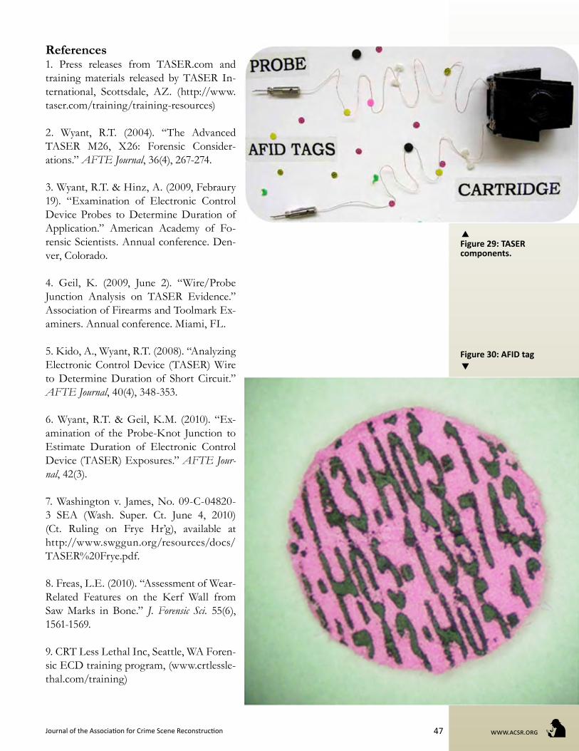
In addition to the probes and wires de-scribed above, there are other components to a fired TASER cartridge that should be collected. AFIDs, or Anti-Felon Identifica-tion tags, are dispensed with each TASER cartridge. These confetti-like disks contain the microscopic serial number of the fired cartridge and can provide an approximate location of the deployment. There are three colors of AFIDs in each cartridge (pink, yellow, and clear). The pink tags typically fluoresce under FLS (forensic light source). In addition, blast doors, foam disks, probe protectors, and Mylar strips all come out the front of the cartridge when deployed. We recommend that the investigator attend a course and witness what disperses from a TASER cartridge when fired. As with all other potential evidence: “If you see it, bag it”.
Figure 24: Accordion shape of wires in cartridge.
Figure 25: Wires stretched (miss-upper image), shape maintained near cartridge (hit-lower image).
Figure 26: Test samples with a typical electrical breach in wire insulation at 1, 5, 10, 20-second in-tervals.

www.acsr.org Volume 17, Issue 3, Summer 201146
ConclusionThe forensic analysis of an ECD inci-
dent begins with the proper collection and preservation of all ECD-related evidence, including the device, cartridges, wires,
probes, and other products of deployment. It is usually necessary to download the fir-ing data shortly after the event, but care must be taken to thoroughly document the download and limit test firing of the device after it is collected. In a major incident, such as an arrest-related death, it is imperative to log the device into evidence and not return it to service. In some instances, testing the
electrical output of the device is prudent. If the evidence is properly collected and doc-umented, qualities present on the probes and wires can be compared to the data re-corded in the device itself. An approximate duration range of electrical energy that the subject received during the incident can be determined with reasonable scientific cer-tainty.
Ultimately, a forensic reconstruction of an ECD event is complex and multi-tiered. The investigator must ensure that all rel-evant evidence, clothing, medical reports, photos, videos, and statements are collect-ed. All of the case information culminates with the analysis, testing, and interpreta-tion of results for a practical reconstruction of the event that most accurately represents what occurred. Credible forensic experts often make efforts to educate CSI-savvy juries on how analyses and reconstructions are realistically performed. Although the same results can usually be achieved in a laboratory, it is wise to recreate the scene and walk the jury through what was done and how conclusions were derived. The au-thors suggest creating a fixture that can be taken into court demonstrating the func-tions of the device, how failures are identi-fied and analyses performed. Meeting with the attorneys ahead of time to demonstrate the examinations is paramount.
In the worst-case scenario, such as an excited delirium related death or a lethal-force shooting, it is common that the fo-cus will be on the ECD and its perceived failure. With a firm knowledge base, the crime scene investigator and forensic sci-entist can successfully investigate and re-construct these cases meanwhile helping to educate juries and judges on the operation and analysis of these devices. As most inef-fective field deployments often have simple answers, proper preservation of the ECD unit and all of the fired components can an-swer many questions.
Figure 27: Leave battery in, remove cartridge.
Figure 28: TASER safety clip (red)
Journal of the Association for Crime Scene Reconstruction www.acsr.org47
References1. Press releases from TASER.com and training materials released by TASER In-ternational, Scottsdale, AZ. (http://www.taser.com/training/training-resources)
2. Wyant, R.T. (2004). “The Advanced TASER M26, X26: Forensic Consider-ations.” AFTE Journal, 36(4), 267-274.
3. Wyant, R.T. & Hinz, A. (2009, Febraury 19). “Examination of Electronic Control Device Probes to Determine Duration of Application.” American Academy of Fo-rensic Scientists. Annual conference. Den-ver, Colorado.
4. Geil, K. (2009, June 2). “Wire/Probe Junction Analysis on TASER Evidence.” Association of Firearms and Toolmark Ex-aminers. Annual conference. Miami, FL.
5. Kido, A., Wyant, R.T. (2008). “Analyzing Electronic Control Device (TASER) Wire to Determine Duration of Short Circuit.” AFTE Journal, 40(4), 348-353.
6. Wyant, R.T. & Geil, K.M. (2010). “Ex-amination of the Probe-Knot Junction to Estimate Duration of Electronic Control Device (TASER) Exposures.” AFTE Jour-nal, 42(3).
7. Washington v. James, No. 09-C-04820-3 SEA (Wash. Super. Ct. June 4, 2010) (Ct. Ruling on Frye Hr’g), available at http://www.swggun.org/resources/docs/TASER%20Frye.pdf.
8. Freas, L.E. (2010). “Assessment of Wear-Related Features on the Kerf Wall from Saw Marks in Bone.” J. Forensic Sci. 55(6), 1561-1569.
9. CRT Less Lethal Inc, Seattle, WA Foren-sic ECD training program, (www.crtlessle-thal.com/training)
Figure 29: TASER components.
Figure 30: AFID tag

www.acsr.org Volume 17, Issue 3, Summer 201148